Proceedings of Math and Design, Blumenau, Brazil, July 2007ddunham/md07paper.pdf · Proceedings of...
9
Proceedings of Math and Design, Blumenau, Brazil, July 2007 CREATING REGULAR REPEATING HYPERBOLIC PATTERNS Douglas Dunham, University of Minnesota Duluth, USA Keywords: computer algorithms, repeating patterns, hyperbolic geometry, M.C. Escher art. Abstract: The Dutch artist M.C. Escher created many repeating symmetric patterns. In fact he utilized each of the three “classical” geometries: the sphere, the Euclidean plane, and the hyperbolic plane. Many of Escher’s patterns are based on regular tessellations – tilings by regular polygons. Replicating a repeating pattern of the sphere or Euclidean plane from a motif is straightforward, but replicating a repeating hyperbolic pattern presents challenges. In this paper we describe an algorithm for replicating repeating patterns of the hyperbolic plane. 1. INTRODUCTION M.C. Escher is perhaps best known for his repeating patterns of the Euclidean plane, but he also created repeating spherical and hyperbolic patterns. Due to the difficulties inherent in creating hyperbolic patterns, Escher only created four of them: Circle Limit I, Circle Limit II, Circle Limit III, and Circle Limit IV, each being based on a regular hyperbolic tessellation. Figure 1 shows how Circle Limit I is based on the regular tessellation {6,4}. Figure 1. The {6,4}tessellation superimposed on Escher’s Circle Limit I pattern.
Transcript of Proceedings of Math and Design, Blumenau, Brazil, July 2007ddunham/md07paper.pdf · Proceedings of...

Proceedings of Math and Design, Blumenau, Brazil, July 2007
CREATING REGULAR REPEATING HYPERBOLIC PATTERNS
Douglas Dunham, University of Minnesota Duluth, USA
Keywords: computer algorithms, repeating patterns, hyperbolic geometry, M.C. Escher art.
Abstract:
The Dutch artist M.C. Escher created many repeating symmetric patterns. In fact he utilized each of the three
“classical” geometries: the sphere, the Euclidean plane, and the hyperbolic plane. Many of Escher’s patterns are
based on regular tessellations – tilings by regular polygons. Replicating a repeating pattern of the sphere or
Euclidean plane from a motif is straightforward, but replicating a repeating hyperbolic pattern presents
challenges. In this paper we describe an algorithm for replicating repeating patterns of the hyperbolic plane.
1. INTRODUCTION
M.C. Escher is perhaps best known for his repeating patterns of the Euclidean plane, but he
also created repeating spherical and hyperbolic patterns. Due to the difficulties inherent in
creating hyperbolic patterns, Escher only created four of them: Circle Limit I, Circle Limit II,
Circle Limit III, and Circle Limit IV, each being based on a regular hyperbolic tessellation.
Figure 1 shows how Circle Limit I is based on the regular tessellation {6,4}.
Figure 1. The {6,4}tessellation superimposed on Escher’s Circle Limit I pattern.

Our ultimate goal is to create aesthetically pleasing repeating hyperbolic patterns. There are
two steps involved in creating a repeating pattern in one of the classical geometries: first a
motif must be designed, and second the motif must be transformed around the plane (or
sphere). In a previous paper we described how to design a hyperbolic motif [2]. The goal of
this paper is to describe a computer algorithm to perform the second step – transformation of
the motif around the plane; this process is called replication. More than 20 years ago we
published a limited replication algorithm that could not produce the Circle Limit I pattern for
example [1]. The replication of a hyperbolic pattern is quite tedious when done by hand, as
Escher did. This is undoubtedly the reason he didn’t create more hyperbolic patterns.
In the next section we review basic concepts, including hyperbolic geometry, repeating
patterns, and regular tessellations. Then we describe the replication algorithm. Next we show
some sample patterns. Finally we indicate directions of future research.
2. HYPERBOLIC GEOMETRY AND REGULAR TESSELLATIONS
Hyperbolic geometry is the least familiar of the three classical geometries. This is probably
because it has no smooth distance-preserving embedding into ordinary Euclidean space,
unlike the sphere and the Euclidean plane. This was proved in 1901 by the German
mathematician David Hilbert. Thus we must rely on models of hyperbolic geometry that
distort distance perforce.
Escher used the Poincaré circle model of hyperbolic geometry. This model was particularly
appealing to Escher since it represents the entire hyperbolic plane within a finite area – the
interior of a Euclidean circle. It also has a second aesthetically appealing property: it is
conformal, which means that the hyperbolic measure of an angle is the same as its Euclidean
measure. The conformal property also means that in repeating patterns, transformed copies of
the motif have roughly the same shape, and so remain recognizable even if they are small to
our Euclidean eyes. The “points” of this model are just the interior points of the bounding
circle; the “lines” are circular arcs orthogonal to the bounding circle (including diameters as
special cases). The arcs making up the {6,4} tessellation in Figure 1 represent hyperbolic
lines, as do the backbones of the fish. Note that distance is measured in such a way that all the
white fish in Figure 1 are the same hyperbolic size, as are the black fish. Thus equal
hyperbolic distances are represented by ever smaller Euclidean distances toward the edge of
the bounding circle.

A repeating pattern of one of the classical geometries is made up of congruent copies of a
basic subpattern or motif. The copies of the motif should not overlap, and a characteristic of
Escher’s repeating patterns is that there are no gaps either – that is, the copies of the motif
exactly fill up the space (unlike standard wallpaper patterns in which there is usually
“background” between the motif figures). In Escher’s Circle Limit I, a motif consists of half a
white fish together with half an adjacent black fish. Such a motif is shown in Figure 2.
Similarly one of the hexagons in the tessellation of Figure 1 can be decomposed into 12 right
triangles by diameters and perpendicular bisectors of sides of the hexagon; one such triangle is
the motif for the hexagon tessellation (ignoring the fish).
Figure 2. A motif for the Circle Limit I pattern.
An important kind of repeating pattern in any of the classical geometries is the regular
tessellation, denoted {p,q}, by regular p-sided polygons, or p-gons, meeting q at each vertex.
It is necessary that (p-2)(q-2) > 4 for {p,q} to be hyperbolic (if (p-2)(q-2) = 4, {p,q} is
Euclidean, and if (p-2)(q-2) < 4, {p,q} is spherical). In addition to Circle Limit I, Escher also
used {6,4} as the underlying tessellation for Circle Limit IV. Escher use the tessellation
{8,3}as the basis for both Circle Limit II and Circle Limit III. Figure 3 shows how Circle
Limit III is based on the {8,3} tessellation.

Figure 3. The {8,3} tessellation superimposed on Escher’s Circle Limit III pattern.
3. THE REPLICATION ALGORITHM
The process of transforming copies of the motif around the hyperbolic plane and drawing
them is called replication. Replication makes sense for repeating Euclidean or spherical
patterns too. However, those cases are easier since there are only a finite number of motif
copies for spherical patterns, and Euclidean patterns can be formed by repeatedly applying
translations in two different directions (after first applying a few reflections, rotations, or glide
reflections to obtain a “translation unit” which we call a “p-gon pattern” below).
Since we wish to replicate patterns that are based on the {p,q}tessellations, we assume that the
motif is contained in a p-gon. Then in order to simplify the algorithm, we first form what we
call the p-gon pattern by appropriately rotating the motif about the p-gon center and/or
reflecting it across diameters and perpendicular bisectors of edges until the p-gon is filled with
motifs. Some of the motif copies may protrude from the p-gon as long as there are
corresponding indentations so that the final pattern will fit together like a jigsaw puzzle. Only
some of the reflections may be used, and the rotations may be some (but not all) multiples of
2π/p. Figure 4 shows the p-gon pattern for the Circle Limit I pattern of Figure 1. Here we
have used reflections across diameters (but not edge bisectors) and rotations by 120 and 240
degrees (but not 60, 180, or 300 degrees).
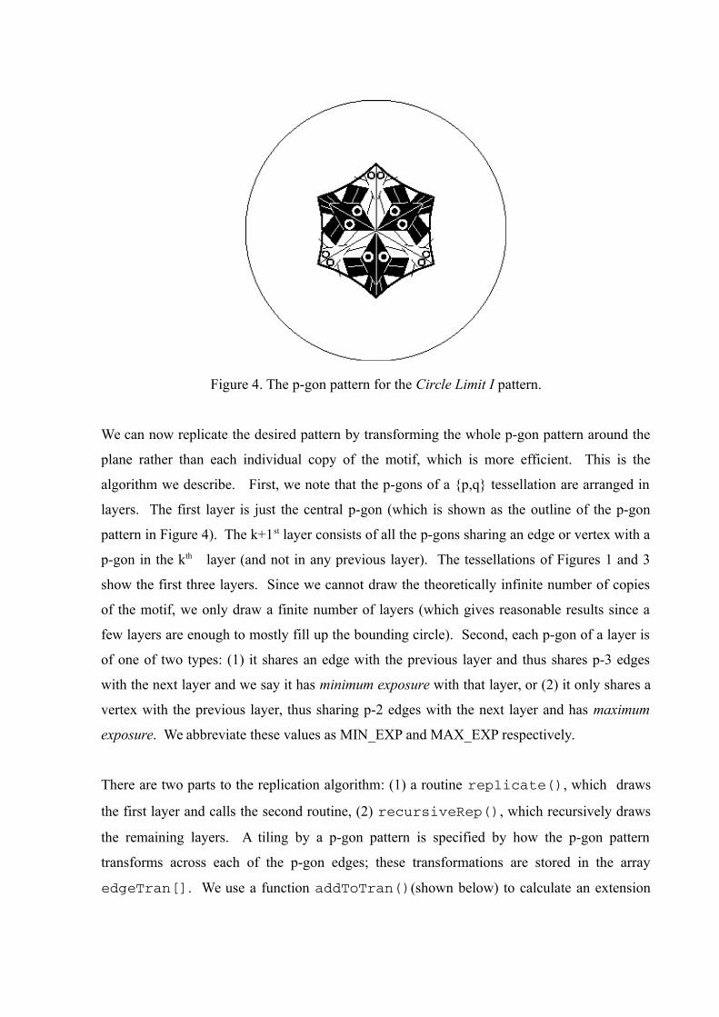
Figure 4. The p-gon pattern for the Circle Limit I pattern.
We can now replicate the desired pattern by transforming the whole p-gon pattern around the
plane rather than each individual copy of the motif, which is more efficient. This is the
algorithm we describe. First, we note that the p-gons of a {p,q} tessellation are arranged in
layers. The first layer is just the central p-gon (which is shown as the outline of the p-gon
pattern in Figure 4). The k+1st layer consists of all the p-gons sharing an edge or vertex with a
p-gon in the kth layer (and not in any previous layer). The tessellations of Figures 1 and 3
show the first three layers. Since we cannot draw the theoretically infinite number of copies
of the motif, we only draw a finite number of layers (which gives reasonable results since a
few layers are enough to mostly fill up the bounding circle). Second, each p-gon of a layer is
of one of two types: (1) it shares an edge with the previous layer and thus shares p-3 edges
with the next layer and we say it has minimum exposure with that layer, or (2) it only shares a
vertex with the previous layer, thus sharing p-2 edges with the next layer and has maximum
exposure. We abbreviate these values as MIN_EXP and MAX_EXP respectively.
There are two parts to the replication algorithm: (1) a routine replicate(), which draws
the first layer and calls the second routine, (2) recursiveRep(), which recursively draws
the remaining layers. A tiling by a p-gon pattern is specified by how the p-gon pattern
transforms across each of the p-gon edges; these transformations are stored in the array
edgeTran[]. We use a function addToTran()(shown below) to calculate an extension

of a transformation by one of the edgeTran[]s. We also keep the number of layers to be
drawn in the global variable maxLayer. Here is pseudocode for replicate():
Replicate ( motif ) {
drawPgon ( motif, IDENT ) ; // Draw central pgon pattern
for ( i = 1 to p ) { // Iterate over each vertex
qTran = edgeTran[i1]
for ( j = 1 to q2 ) { // Iterate around a vertex
exposure = (j == 1) ? MIN_EXP : MAX_EXP ;
recursiveRep ( motif, qTran, 2, exposure ) ;
qTran = addToTran ( qTran, 1 ) ; //1 anticlockwise
}
}
}
In order to describe the function addToTran(), we first note that our transformations
contain (in addition to a matrix) the orientation and an index, pPosition, of the edge across
which the last transformation was made (edgeTran[i].pPosition is the edge that is
matched with edge i in the tiling). Here is the code for addToTran():
addToTran ( tran, shift ) {
if ( shift % p == 0 ) return tran ;
else return computeTran ( tran, shift ) ;
}
where computeTran() is:
computeTran ( tran, shift ) {
newEdge = (tran.pPosition + tran.orientation * shift) % p ;
return tranMult ( tran, edgeTran[newEdge] ) ;
}
and where tranMult ( t1, t2 ) multiplies the matrices and orientations, sets the
pPosition to t2.pPosition, and returns the result.

Here is recursiveRep():
recursiveRep ( motif, initialTran, layer, exposure ) {
DrawPgon ( motif, initialTran ) ; // Draw the pgon pattern
if ( layer < maxLayer ) { // If any more layers
pShift = ( exposure == MIN_EXP ) ? 1 : 0 ;
verticesToDo = ( exposure == MIN_EXP ) ? p3 : p2 ;
for ( i = 1 to verticesToDo ) { // Iterate over vertices
pTran = computeTran ( initialTran, pShift ) ;
qSkip = ( i == 1 ) ? 1 : 0 ;
qTran = addToTran ( pTran, qSkip ) ;
pgonsToDo = ( i == 1 ) ? q3 : q2 ;
for ( j = 1 to pgonsToDo ) { // Iterate about a vertex
newExposure = ( i == 1 ) ? MIN_EXP : MAX_EXP ;
recursiveRep(motif, qTran, layer+1, newExposure);
qTran = addToTran ( qTran, 1 ) ;
}
pShift = (pShift + 1) % p ; // Advance to next vertex
}
}
}
where drawPgon() simply multiplies each of the point vectors of the motif by the
transformation and draws the transformed motif. The algorithm above is a simplified version
that draws multiple copies for the cases p = 3 or q = 3; the same general technique works for
those cases though, but with different values of the variables pShift, verticesToDo, qSkip, etc.
4. SAMPLE PATTERNS
In this section we show some sample patterns based on regular hyperbolic tessellations. In
Figure 5 we show a sample pattern based on the {5,5} tessellation. The fish in this pattern are
designed after the fish in Escher’s Notebook Drawing 20 [3 page 131], which is based on the
Euclidean tessellation {4.4}.

Figure 5. A fish pattern based on the {5,5} tessellation.
Figure 6 shows a hyperbolic pattern of lizards based on the {8,3} tessellation. The fish are
drawn in the style of Escher’s Notebook Drawing 25 [3 page 135], which is based on the
Euclidean {6,3} tessellation.
Figure 6. A pattern of lizards based on the {8,3} tessellation.
Figure 7 shows a butterfly pattern based on the {7,3} tessellation. The butterflies are drawn in
the style of Escher’s Notebook Drawing 70 [3 page 172], which, is also based on the
Euclidean {6,3} tessellation.
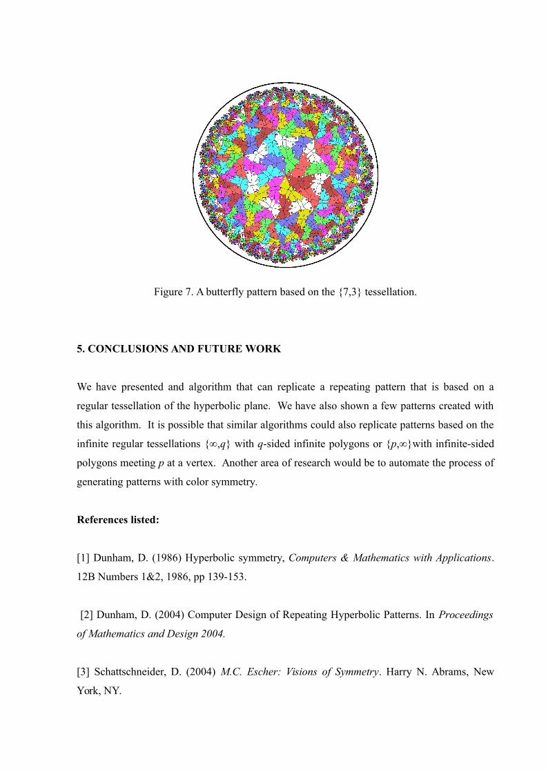
Figure 7. A butterfly pattern based on the {7,3} tessellation.
5. CONCLUSIONS AND FUTURE WORK
We have presented and algorithm that can replicate a repeating pattern that is based on a
regular tessellation of the hyperbolic plane. We have also shown a few patterns created with
this algorithm. It is possible that similar algorithms could also replicate patterns based on the
infinite regular tessellations {∞,q} with q-sided infinite polygons or {p,∞}with infinite-sided
polygons meeting p at a vertex. Another area of research would be to automate the process of
generating patterns with color symmetry.
References listed:
[1] Dunham, D. (1986) Hyperbolic symmetry, Computers & Mathematics with Applications.
12B Numbers 1&2, 1986, pp 139-153.
[2] Dunham, D. (2004) Computer Design of Repeating Hyperbolic Patterns. In Proceedings
of Mathematics and Design 2004.
[3] Schattschneider, D. (2004) M.C. Escher: Visions of Symmetry. Harry N. Abrams, New
York, NY.