Proceedings of ASME Turbo Expo 2016: Turbomachinery ...
15
1 Proceedings of ASME Turbo Expo 2016: Turbomachinery Technical Conference and Exposition GT2016 June 13 – 17, 2016, Seoul, South Korea GT2016-57857 Review of Coal-To-Synthetic Natural Gas (SNG) Production Methods and Modeling of SNG Production in an Entrained-Flow Gasifer Xijia Lu* and Ting Wang Energy Conversion& Conservation Center University of New Orleans New Orleans, LA 70148, USA Abstract In this paper, the coal-to-synthetic natural gas (SNG) technologies have been reviewed. Steam-oxygen gasification, hydrogasification, and catalytic steam gasification are the three major gasification processes used in coal-to-SNG production. So far, only the steam-oxygen gasification process is commercially proven by installing a catalytic methanation reactor downstream of the gasification process after syngas is produced, cleaned, and shifted to achieve an appropriate H 2 /CO ratio for methanation reaction. This process is expensive, less efficient, and time consuming. Ideally, it will be more effective and economic if methanation could be completed in an once- through entrained-flow gasifier. Technically, this idea is challenging because an effective gasification process is typically operated in a high-pressure and high-temperature condition, which is not favorable for methanation reaction, which is exothermic. To investigate this idea, a computational model is established and a sensitivity study of methanation reactions with and without catalysts are conducted in this study. In modeling the methanation process in a gasifier, correct information of the reaction rates is extremely important. Most of known methanation reaction rates are tightly linked to the catalysts used. Since the non-catalytic reaction rates for methanation are not known in a gasifer and the issues are compounded by the fact that inherent minerals in coal ashes can also affect the methanation kinetics, modeling of methanation in an entrained-flow gasifier becomes very challenging. Considering these issues, instead of trying to obtain the correct methnation reaction rate, this study attempts to use computational model as a convenient tool to investigate the sensitivity of methane production under a wide range methanation reaction rates with and without catalysts. From this sensitivity study, it can be learned that the concept of implementing direct methanation in a once-through entrained- flow gasifier may not be attractive due to competitions of other reactions in a high-temperature environment. The production of SNG is limited to about 18% (vol) with catalytic reaction with a pre-exponential factor A in the order of 10 7 . A further increase of the value of A to 10 11 doesn't result in more production of SNG. This SNG production limit could be caused by the high- temperature and short residence time (3- 4 seconds) in the entraind-flow gasifier. 1 Introduction SNG has a large potential market, particularly for countries that don't have domestic natural gas (NG) resources and relies on importing expensive foreign Liquefied Nature Gas (LNG). Basically any application that currently uses natural gas could use SNG. In particular, gasification can be used on-site for industrial applications to produce SNG, allowing continued operation of natural gas equipment, but from a coal source. Other than producing electricity, industrial use of natural gas was about 28% of the total domestic consumption in United States. A study from the National Energy Technologies Laboratory (NETL) in 2007 researched on the feasibility of on- site gasifiers in industrial facilities for the production of SNG found that many industrial sites could benefit from the use of relatively small gasifier systems to either produce SNG or generate power, H 2 , or syngas. This is particularly attractive to countries that don't produce NG domestically and have concerns on their national energy security. Several advantages are associated with producing SNG from coals for countries without NG resources. SNG can be produced through the gasification of coal and modern gas cleanup system before used for combustion. In this approach, SNG is able to substitute for natural gas, a more volatile commodity than coal. In this way, gasification of coals to SNG helps increase fuel diversity, protecting against an over-reliance on a single energy source, and making utilization of coals much cleaner than the conventional coal burning scheme. Since SNG in use is identical to natural gas, SNG can be transported and distributed using existing natural gas infrastructure and utilized in existing natural gas–fired power plants or devices such as industrial burners, boilers, kilns, etc. Furthermore, natural gas is the fuel that powers most (but not quite all) chemical and refining processes, and natural gas is the feedstock for hydrogen production (for hydro-cracking, hydro-desulfurization, and ammonia) and syngas production (for methanol, and its derivatives e.g. MTBE, formaldehyde, and acetic acid). Natural gas condensate (ethane and propane) is an advantaged raw material via ethylene and propylene to much of the organic chemicals industry (compared to crude-oil-derived naphtha). The biomass can also be used along with coal to produce SNG. The use of biomass would reduce the greenhouse gas ------------------------------------------------------------- * Xijia Lu is now affiliated with 8 Rivers Capital.
Transcript of Proceedings of ASME Turbo Expo 2016: Turbomachinery ...
1
Proceedings of ASME Turbo Expo 2016: Turbomachinery Technical Conference and Exposition GT2016
June 13 – 17, 2016, Seoul, South Korea
GT2016-57857
Review of Coal-To-Synthetic Natural Gas (SNG) Production Methods and Modeling of SNG Production in an Entrained-Flow Gasifer
Xijia Lu* and Ting Wang
Energy Conversion& Conservation Center University of New Orleans
New Orleans, LA 70148, USA
Abstract
In this paper, the coal-to-synthetic natural gas (SNG)
technologies have been reviewed. Steam-oxygen gasification,
hydrogasification, and catalytic steam gasification are the three
major gasification processes used in coal-to-SNG production.
So far, only the steam-oxygen gasification process is
commercially proven by installing a catalytic methanation
reactor downstream of the gasification process after syngas is
produced, cleaned, and shifted to achieve an appropriate H2/CO
ratio for methanation reaction. This process is expensive, less
efficient, and time consuming. Ideally, it will be more effective
and economic if methanation could be completed in an once-
through entrained-flow gasifier. Technically, this idea is
challenging because an effective gasification process is
typically operated in a high-pressure and high-temperature
condition, which is not favorable for methanation reaction,
which is exothermic. To investigate this idea, a computational
model is established and a sensitivity study of methanation
reactions with and without catalysts are conducted in this study.
In modeling the methanation process in a gasifier, correct
information of the reaction rates is extremely important. Most
of known methanation reaction rates are tightly linked to the
catalysts used. Since the non-catalytic reaction rates for
methanation are not known in a gasifer and the issues are
compounded by the fact that inherent minerals in coal ashes can
also affect the methanation kinetics, modeling of methanation
in an entrained-flow gasifier becomes very challenging.
Considering these issues, instead of trying to obtain the correct
methnation reaction rate, this study attempts to use
computational model as a convenient tool to investigate the
sensitivity of methane production under a wide range
methanation reaction rates with and without catalysts. From this
sensitivity study, it can be learned that the concept of
implementing direct methanation in a once-through entrained-
flow gasifier may not be attractive due to competitions of other
reactions in a high-temperature environment. The production of
SNG is limited to about 18% (vol) with catalytic reaction with a
pre-exponential factor A in the order of 107. A further increase
of the value of A to 1011 doesn't result in more production of
SNG. This SNG production limit could be caused by the high-
temperature and short residence time (3- 4 seconds) in the
entraind-flow gasifier.
1 Introduction
SNG has a large potential market, particularly for countries
that don't have domestic natural gas (NG) resources and relies
on importing expensive foreign Liquefied Nature Gas (LNG).
Basically any application that currently uses natural gas could
use SNG. In particular, gasification can be used on-site for
industrial applications to produce SNG, allowing continued
operation of natural gas equipment, but from a coal source.
Other than producing electricity, industrial use of natural gas
was about 28% of the total domestic consumption in United
States. A study from the National Energy Technologies
Laboratory (NETL) in 2007 researched on the feasibility of on-
site gasifiers in industrial facilities for the production of SNG
found that many industrial sites could benefit from the use of
relatively small gasifier systems to either produce SNG or
generate power, H2, or syngas. This is particularly attractive to
countries that don't produce NG domestically and have
concerns on their national energy security.
Several advantages are associated with producing SNG from
coals for countries without NG resources. SNG can be
produced through the gasification of coal and modern gas
cleanup system before used for combustion. In this approach,
SNG is able to substitute for natural gas, a more volatile
commodity than coal. In this way, gasification of coals to SNG
helps increase fuel diversity, protecting against an over-reliance
on a single energy source, and making utilization of coals much
cleaner than the conventional coal burning scheme. Since SNG
in use is identical to natural gas, SNG can be transported and
distributed using existing natural gas infrastructure and utilized
in existing natural gas–fired power plants or devices such as
industrial burners, boilers, kilns, etc. Furthermore, natural gas is
the fuel that powers most (but not quite all) chemical and
refining processes, and natural gas is the feedstock for
hydrogen production (for hydro-cracking, hydro-desulfurization,
and ammonia) and syngas production (for methanol, and its
derivatives e.g. MTBE, formaldehyde, and acetic acid). Natural
gas condensate (ethane and propane) is an advantaged raw
material via ethylene and propylene to much of the organic
chemicals industry (compared to crude-oil-derived naphtha).
The biomass can also be used along with coal to produce
SNG. The use of biomass would reduce the greenhouse gas
------------------------------------------------------------- * Xijia Lu is now affiliated with 8 Rivers Capital.

2
emissions, as biomass is a carbon-neutral fuel. In addition, the
development of SNG technology would also enhance other
gasification-based technologies such as hydrogen generation,
the Integrated Gasification Combined Cycle (IGCC), or coal-to-
liquid technologies, as the production of SNG is at least similar
to these other processes/technologies (Chandel and Williams,
2009 [1]). The addition of a water-gas shift reaction system and
methanation reactor to the base gasification and gas cleanup
system, as illustrated in Fig.1, allows for the production of SNG
that meets pipeline quality natural gas specifications. The
Reference Plant in Fig. 1 uses a sour-shift reaction to increase
the hydrogen concentration in a portion of the syngas from the
gasifier, so that when this gas stream is mixed with the
remainder of the syngas and is cleaned in the Rectisol® AGR
system, the cleaned syngas has the proper hydrogen to carbon
ratio (3:1) for methanation ( DOE report, 2007 [2]).
Figure 1 Sketch of Major Systems Comprising SNG Production Reference Plant (DOE report, 2007 [2])
There are also many challenges associated with the
deployment of SNG. In a 2007 DOE/NETL study [2], potential
industrial customers of coal-to-SNG gasification for onsite use
in NG applications indicated that reliability is important and
needs to be near 100%, either through increased performance or
redundancy. Some applications are able to also fire oil,
allowing for onsite storage of the backup fuel. Availability is
still a challenge for gasification, although some sites have
achieved very high availability. The Great Plains Synfuels Plant
in Beulah, North Dakota, for example, has consistently
produced 90- 92% of its rated output capacity [2].
In United States, producing SNG from coal is more
expensive than producing natural gas through hydraulic
fracturing (fracking) process. For this reason, NETL focuses on
locations and applications where the gasifier could be
integrated with an industrial process that uses natural gas. This
would improve plant economics and would guard the facility
against fluctuating natural gas prices, because existing coal
transport infrastructure is well-developed, and coal is both
abundant and relatively inexpensive. Another challenge to coal-
to-SNG is in transporting a gaseous fuel, which can be difficult
because of the gases’ low densities. SNG must be cooled and
then compressed for transport through a close-to-capacity
pipeline infrastructure. In addition, pipelines are restricted by
geographical features like oceans, for example. It can be
liquefied (i.e., as Liquefied Natural Gas or LNG) for transport
by ships or trucks.
1.1 Coal-to-SNG Technology
Steam-oxygen gasification, hydrogasification, and catalytic
steam gasification are the three gasification processes used in
coal-to-SNG technology. So far, the proven and
commercialized method of gasification for the coal-to-SNG
process is the steam-oxygen gasification process. A review of
these processes is conducted below.
1.1.1 Steam-oxygen gasification
In the steam‐oxygen process of converting coal to SNG, coal
is gasified with steam and oxygen. Oxygen is used for partial-
combustion with char to provide enough energy used for
gasification process. The gasification process produces carbon
monoxide (CO), hydrogen (H2), carbon dioxide (CO2), methane
(CH4), and higher hydrocarbons such as ethane (C2H6) and
propane (C3H8). The gas composition depends upon the
gasifier's operating conditions, i.e., temperature and pressure.
At higher temperatures and pressures, the major products are
CO and H2. Three moles of H2 are required to react with each
mole of CO to produce one mole of CH4. The concentration of
H2 in syngas is increased by a step called the water‐gas shift
reaction, which is followed by gas cleaning. The cleaned gas,
consisting primarily of CO and H2, reacts in the methanation
reactor in the presence of a catalyst to produce CH4 and H2O.
The resulting gas, after H2O condensation and polishing, if
required, is called synthetic natural gas (SNG). Figure 2 shows
the flow diagram of the steam‐oxygen gasification process. The
essential components of the process are the air separation unit,
the gasifier, the water‐gas shift reactor, the syngas cleanup
system, and the methanation reactor.
Figure 2 The steam-oxygen gasification process diagram (Chen, L., et al., 2009 [3])
The methanation reaction with catalysts which are mainly
ruthenium, cobalt, nickel and iron can be described by
CO + 3H2 CH4 + H2O (1)
As the methanation reactions are highly exothermic and
pressure-favorable, the methanation reactors are designed to run
at low temperature and high pressure with catalysts. In the
methanation reactor, CO and H2 are converted to CH4 and H2O
in a fixed‐bed catalytic reactor. Since methanation is an
exothermic reaction, the increase in temperature is controlled
by recycling the product gas or by using a series of reactors.
Steam is added to the reaction to avoid coke formation in the
reactor. After the steam is removed from the product gases by
condensation, SNG is ready for commercial applications. A
conventional design for the methanation process uses three
stages. Figure 3 shows the schematic diagram of the ADAM II
methanation process, illustrating the three-stage design
documented in Hohlein et al., 1984 [4]. Three adiabatic

3
methanation reactors, D 201, D 202 and D 203 are equipped
with fixed catalytic beds. The syngas coming from the WGS
unit is preheated to a temperature above the starting
temperature of the catalyst. At each methanation reactor outlet,
the gas compositions are approximately at chemical equilibrium.
Heat is generated during the methanation reactions, so syngas
cooling is needed between stages. The typical operating
Figure 3 ADAM II 3-stage methanation process at 45 bar, 300-650 ºC (Hohlein et al., 1984[4])
temperatures and compositions at the inlets and outlets of the
three stages are shown in Table 1. (Chen, L., et al., 2009 [3])
Table 1 Typical operating conditions and gas compositions in the 3-stage methanation process. (Chen, L., et al., 2009 [3])
The steam‐oxygen gasification process for SNG has been
demonstrated in the Great Plains Synfuel Plant for 20 years and
has proven to be successful in practice. The interest in the Coal
to SNG concept has grown recently due to the process’s
capability for CO2 capture and utilization in enhanced oil
recovery. In the Great Plains Synfuel Plant (GPSP), more than
5 million tons of CO2 have been sequestered up to 2006, which
doubled the oil recovery rate of an oil field in Saskatchewan. A
detailed process diagram of the GPSP is shown in Fig. 4 (DOE,
2006).
Figure 4 Detailed block flow diagram of the Great Plains Synfuel Plant. (Source: DOE report, April, 2006[5])
The plant consists of a coal and ash handling unit, an Air
Separation Unit (ASU), a steam generator, a gasifier, a water
gas shift reactor, and a methanation unit. Also included are the
AGR plant (Rectisol) and Flue Gas Desulphurization (FGD)

4
unit, which are used to remove the acid gas within the syngas
and flue gas, respectively. Besides methane, the plant also
produces ammonia, ammonium sulfate, naphtha, and phenol
(carbolic acid) as by-products. Although demonstrating
successful and economical clean synthetic fuels production, the
GPSP can be further optimized in many aspects. For instance,
the gasification technology, a Lurgi system, was adopted by the
GPSP 20 years ago and may not be the most favorable option
today because of its small coal processing throughput and large
production of waste water. Choosing a technology that
produces less waste could eliminate or diminish ancillary
processes such as gas liquor separation, wastewater treatment,
ash handling, and so on. However, replacing the gasification
system would require the adjustment of other processes,
principally the WGS and methanation systems.
1.1.2 Hydrogasification
The hydrogasification process uses H2 to gasify coal. H2
reacts with coal to produce CH4. The hydrogasification process
is exothermic in nature. H2 required for the gasification is either
provided by an external source or by using a methane steam
reformer. A portion of the CH4 generated in the
hydrogasification reactor is converted into CO and H2 in the
methane steam reformer. The methane steam reforming
reaction is: H2O + CH4 → CO + 3H2. 1 mole of CH4 produced
from hydrogasification process could generate 3 moles of H2 in
the methane steam reformer. During the hydrogasification
process, C +2H2 CH4, only 2 moles of H2 are needed for
producing one mole of CH4. That is the reason why H2 required
for hydrogasification can be provided by using a methane steam
reformer. If CO is shifted to CO2 and H2, the above process will
lead to a net production of one mole of CH4 and CO2 from two
moles of fixed carbon: 2C+2H2OCH4+CO2. A diagram of the
hydrogasification process is shown in Fig. 5. The
hydrogasification process is still in the research stage and is not
yet commercialized, although a few studies on the process were
conducted as early as from the 1970s to the 1990s. Ruby et al.
(2008) [6] proposed a hydrogasification process which consists
of a hydrogasification reactor, desulfurization and carbonizer
reactors for CO2 removal, and a methanation reactor.
Figure 5 Hydrogasification process diagram (Chandel, M., and Williams, E., 2009 [1])
Hydrogasification was originally developed in the early
1900s and there was a revived interest in the process during the
1970s and 80s as a result of increasing natural gas prices. The
basic reaction is the direct methanation of carbon, as shown
below.
C +2H2 CH4 H1000K = -89.9kJ/mol (2)
Although this reaction is mildly exothermic, a significant
amount of energy must be spent in bringing the reactants up to
the operating temperature as well as to sustain the process.
Methane production is favored at high pressures and the
process is generally operated at temperatures ranging from 750
ºC to 1000 ºC (Higman and Burgt, 2003 [7]). A number of
processes were developed and a few of these were operated
satisfactorily in pilot plant scales. A major issue with
hydrogasification process is the source of the hydrogen supply
since hydrogen production can be expensive and hydrogen has
a better market value. As natural gas prices have dropped due to
the recent development of hydraulic fracturing (or fracking),
hydrogasification is not attractive, economically. In addition,
the much slower reactivity of carbon with hydrogen compared
to other gasifying agents further hinders the commercialization
of hydrogasification. The reactivity of carbon with different
species at 1073 K and 0.1 atmospheres are shown below
(Walker et al., 1959 [8]): RO2 (105)>> RH2O(3) > RCO2 (1) > RH2
(3.1-3) .
Based on the above discussions, it is evident that, for SNG
production to be commercially viable, the gasification process
must solve the two major technical problems faced by
conventional hydrogasification and methanation processes.
These problems are the difficulties in supplying hydrogen in an
inexpensive and simple manner, and also the low carbon
conversion ratios observed during conventional
hydrogasification based processes.
1.1.3 Hydromethanation (Catalytic steam gasification)
Catalysts can be used to enhance the reactions involved in
gasification. Many gasifiers must operate at high temperatures
so that the gasification reactions will proceed at reasonable
rates. Catalysts can also be used to favor or suppress the
formation of certain components in the syngas product. The
primary constituents of syngas are hydrogen (H2) and CO, but
other products like methane are formed in small amounts.
Catalytic gasification can be used to either promote methane
formation, or suppress it. Disadvantages of catalytic
gasification include increased materials costs for the catalyst
itself, as well as diminishing catalyst performance over time.
Catalysts can be recycled, but their performance tends to
diminish with age. The relative difficulty in reclaiming and
recycling the catalyst can also be a disadvantage.
In the hydromethanation process, gasification and
methanation occur in the same reactor in the presence of a
catalyst. Steam is the only gasification agent used so that the
water-gas shift. The net reaction route is:
2C + 2H2O CH4 +CO2 (3)
However, with steam, low temperatures greatly limit the rate
of reaction. At high temperatures, the thermodynamic
environment is not favorable for methane production. Therefore,
introducing a catalyst at low temperature to facilitate the
reaction is highly needed. Alkali metals catalyze carbon with
steam to form CO and H2 and, by doing so, increase the
reaction rate several fold. Selection of the catalyst is based on
its affinity to reacting with coal. KCl and K2SO4, for example,
are ineffective despite their belonging to the alkali family
(Probstein and Hicks, 1982 [9]). In the process of gasification,
the actual catalyst is not retained in the gasifier, but is carried
5
out with the ash. In order for a commercial plant to maximize
profits, it is essential that a recycling loop be implemented to
recover the catalyst for re-use in the coal gasification process.
From end-to-end, in hydromethanation, coal is pulverized and
mixed with the selected catalyst. Before feeding the
impregnated catalyst-coal into the gasifier, it is dried to remove
as much moisture from the fuel as possible. Gasifiers are then
fed with the feedstock and begin introducing steam into the
environment to perform the gasification. Beyond the
hydromethanation process, carbon monoxide and hydrogen
must be separated from the methane product. A cryogenic
distillation process effectively separates methane from the
synthesis gas (a process with an energy penalty lower than the
oxygen separation from air in an ASU).
The advantages of hydrogasification and hydromethanation
are that they do not use direct combustion to provide heat, so an
air separation unit is not required to provide oxygen. Hence,
there is less of an energy penalty for the process. Furthermore,
the costs are lower, as the gasification and methanation occur at
a lower temperature. The disadvantages of hydromethanation
are the production of tar and the separation of the catalyst from
the ash/slag and the loss of reactivity of the catalyst. A diagram
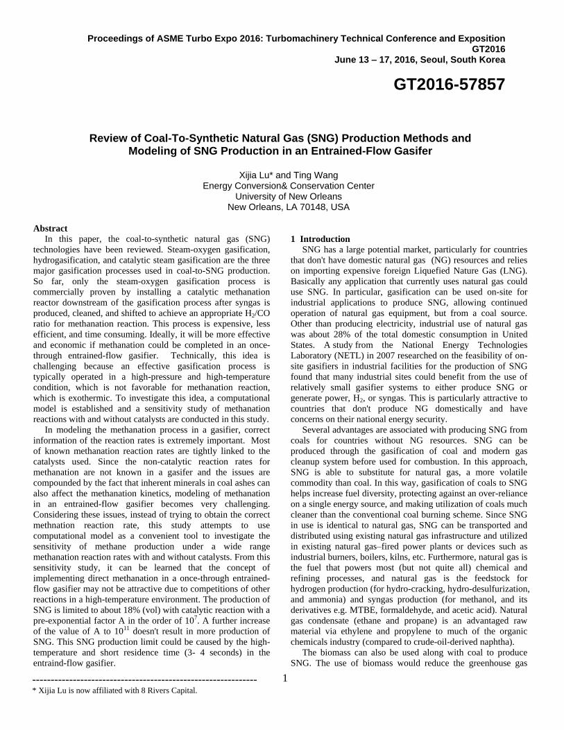
of the hydromethanation process is shown in Fig. 6.
Figure 6 A diagram of hydromethanation process (Chandel, M., and Williams, E., 2009[10])
The hydromethanation process developed by Great Point
Energy Inc. is considered to be a great advancement in SNG
technology. This process was initially developed by Exxon in
the 1970s using potassium carbonate (K2CO3). However, the
current Great Point Energy process involves a single reactor
using a proprietary, recyclable catalyst developed in-house and
made from abundant, low-cost metals. The catalyst was
developed with the help of Southern Illinois University, the
University of Toronto, and the University of Tennessee. The
heat released in the SNG process is sufficient to sustain the
gasification, eliminating the need to fire up the reactions with
purified oxygen. The process was demonstrated with a
weeklong pilot run in November 2007. The pilot plant for the
process is a 60-foot-high gasifier with an internal diameter of
14 inches. The price of pipeline-quality natural gas by Great
Point Energy’s process could be less than $3 per MMBtu
(Fairley 2007). Great Point Energy Inc. and Peabody were
working together to commercialize the technology with the goal
of developing a coal to SNG plant at or near Wyoming’s
Powder River Basin area (GreatPoint Energy 2008[11] [12]).
The Company currently conducts tests at a pilot plant at the
Energy and Environmental Research Center in Grand Forks,
ND, which demonstrates the latest version of its technology and
serves as a feedstock calibration facility for designing
commercial plants (GreatPoint Energy, 2013[13]).
1.2 Use of biomass for SNG
SNG produced from biomass, also known as “bio‐SNG,” has
the advantage of being carbon‐neutral, and, in conjunction with
CO2 capture, the entire process could generate negative carbon
emissions. The challenges of using biomass arise due to the
chemical composition of biomass, lower calorific value, higher
moisture content, and tar formation. The seasonal variation in
the biomass supply and moisture content could require large
amounts of storage space and large drying capacities for
commercial‐scale biomass gasification units. Another possible
way of utilizing biomass would be in a coal-biomass co-
gasification process. Co-gasification could make it possible to
install large-scale gasification plants, which could be more
commercially viable. Fluidized bed gasifiers may be better
suited for biomass gasification than entrained-flow gasifiers as
they can handle variations in size, density, moisture, and tar
formation.
In Meijden’s (2010 [14]) study, he categorized the
gasification technologies associated with bio-SNG process in
different ways. Based on the gasifier’s type, they are: 1)
entrained flow, 2) fluidized bed, and 3) fixed bed. Fluidized bed
gasifiers can be divided into two main categories: Bubbling
Fluidized Bed (BFB) and Circulating Fluidized Bed (CFB). A
bubbling bed is the classical approach where the gas at low
velocities is used and fluidization of the solids is relatively
stationary, with some finer particles being entrained. At higher
gas velocities, a circulation of the bed material is required. This
type of gasifier is called a Circulating Fluidized Bed (CFB)
gasifier. The typical fluidization velocity in the circulating
gasifier is normally between 3 and 10 m/s. The bed material
and recycling char are removed from the product gases by a
cyclone or another separation device. Those particles are
recycled back to the gasifier via a non-mechanical valve. The
gasification technologies can be implemented with a direct
heating scheme or an indirect gasification/heating scheme. For
indirect gasification/heating, the conversion of the fuel is being
done in two separate reactors (indirect twin beds). The first
reactor is for combustion to generate heat for the gasification
process in the second reactor. The char and bed material (e.g.
sand) are fed to the combustion reactor. The char is combusted
to produce the required heat for the gasification reactor. The
bed material (sand) carrying the required heat is then
transported into the gasification reactor. The biomass in the
gasification reactor is converted into producer (or product) gas
and char (pyrolysis). Char and bed material are separated from
the gas and returned into the combustion chamber by a solid
gas separation device, such as a cyclone. The producer gas exits
the gasifier and is sent to the gas cleanup system.
In Meijden’s (2010) [14] study, he used Aspen Plus to
simulate a large scale SNG system with 1 GW (HHV) of input
power. The net overall efficiency on the LHV basis, including
electricity consumption and pretreatment, but excluding
transport of biomass, is 54% for the BFB, 58% for the CFB
with direct heating/gasification, and 67% for the CFB with the
indirect heating/gasification technique.
In lieu of the high efficiency of indirect gasification, the
Energy Research Centre of the Netherlands (ECN) has
demonstrated SNG generation from biomass (Mozaffarian et al.

6
2003, 2004[15] [16]) using the indirect gasification technology
at atmospheric pressure. The process is shown in Fig.7. The
biomass is gasified in the riser of a gasification reactor and the
remaining char is circulated to the combustor. In this process,
the heat required for gasification is supplied by char
combustion in the combustor. Steam is used for gasification and
air is used for char combustion. The lab scale gasifier,
developed in 2004, has a biomass capacity of 5 kg/h and
operates at temperatures of 750ºC to 900ºC (Zwart et al. 2006
[17]). Direct heating/gasification was also tested, which uses
oxygen and steam for gasification via a bubbling fluidized bed
and operates at 850ºC. The gas treatment in the integrated bio-
SNG system consists of tar removal with organic scrubbing
liquid technology, and sulfur and HCl removal with adsorbents.
Figure 7 Simplified scheme of MILENA biomass gasification process (C.M. van der Meijden, 2010[14])
Based on the experiments, the SNG system consists of an
indirect gasifier, the so-called MILENA gasifier (Fig. 7), a tar
removal system which recycles tar to the gasifier, a gas
cleaning and WGS reactor, and a methanation combined
reactor. The gasifier contains separate sections for gasification
and combustion. The gasification section consists of three parts:
the gasifier riser, settling chamber, and downcomer. The red
arrows in Fig. 7 represent the circulating bed material. The
gasifier working at 850ºC produces nearly nitrogen-free syngas
and a high amount of methane. Tar is recycled to the gasifier in
order to increase efficiency, whereas the tar-free syngas is
cleaned from other contaminants (e.g., sulfur and chlorine). The
clean syngas is fed to a combined shift and methanation
process, converting the syngas into SNG. After methanation,
further upgrading (e.g., CO2 and H2O removal) is required in
order to comply with the desired SNG specifications. The
overall net thermal efficiency is reported as 70% by Low
Heating Value (LHV) basis (approximately 64% HHV basis).
Forty percent of the carbon of the biomass becomes part of the
SNG and an equal amount of carbon is captured as CO2. The
remaining 20% of the carbon in biomass becomes flue gas from
the process.
1.3 Recent research on SNG
Recently, The Arizona Public Service Company (APS)
along with the Department of Energy and other partners are
developing a hydrogasification process to co-produce SNG and
electricity from western coals. The objective of the $12.9
million project is to develop and demonstrate an engineering
scale hydrogasification process which can produce SNG at a
cost of less than $5/MMBtu and can utilize low rank western
coal (NETL, 2008 [18]). The Western Research Institute (WRI)
is working on the development of a gasification process which
uses counter-current cyclonic methods in a unique sequence
that causes activated carbon char to react with synthesis gas,
both derived from coal. The method does not require pure
oxygen to produce the synthesis gas (WRI, 2008[19]).
KBR developed a new KBR TRIG gasification-based coal-
to-SNG. The process shown in Fig. 8 is well suited for a wide
range of feedstocks, particularly low-rank coals that are low-
cost and abundant. The process scheme offers a technically
robust and energy efficient design, with several advantages
over comparable gasification processes. The economics of
building mine-mouth 150,000 standard cubic feet per day coal-
to-SNG facilities using KBR’s TRIG gasification technology is
currently being investigated for various western U.S. locations
(Ariyapadi et al., 2008 [20]). Figure 8 depicts a simplified
block flow diagram illustrating the connectivity between major
process units of the KBR system. A cluster of three TRIG
gasifiers supply the necessary syngas feed with the appropriate
H2: CO ratio to the methanation unit. The main process units
include gasification, shift, COS hydrolysis, ammonia scrubbing,
mercury removal, acid gas removal, sulfur removal, CO2
compression, methanation, and SNG drying and compression.
The detail of each section is described by Ariyapadi et al. (2008)
[20].
Figure 8 Block Flow Diagram of KBR TRIG Coal-to-SNG Process (Ariyapadi et al. 2008 [20])
A new SNG production technology, called the steam
hydrogasification reactor (SHR), which is based on a
combination of the hydrogasification and steam pyrolysis
reactions, is newly developed by the University of California,
Riverside. The configuration of this process allows the use of
recycled hydrogen as feed, thus eliminating the hydrogen
7
supply problem. This steam hydrogasification process generates
a product gas stream with high methane content. The
composition of the product gas from steam hydrogasification
can be controlled by varying the steam to carbon and H2 to
carbon ratios of the feed. Methane concentration of the SHR
product gas can be varied from 10 to 30 % on a molar basis.
The product gas also contains CO, CO2, H2, and a considerable
amount of unreacted steam. In the SHR gasifier, the feed is
transported into the reactor via a slurry. The slurry feed
eliminates the need for cumbersome reactor feed systems such
as a lock hopper. This also simplifies feedstock processing
since drying the feed is not necessary. A portion of the
necessary steam enters the reactor as liquid water that is part of
the slurry and the rest of the steam is superheated and fed along
with the hydrogen. Steam hydrogasification of carbonaceous
feedstocks results in improved carbon conversion compared to
hydrogasification. An SHR also generates a product gas with a
considerable amount of methane compared to conventional
partial oxidation gasifiers. The steam hydrogasification reactor
can be coupled with a shift reactor, resulting in a gasifier
configuration that generates a syngas with high methane
concentrations. This configuration also allows considerable
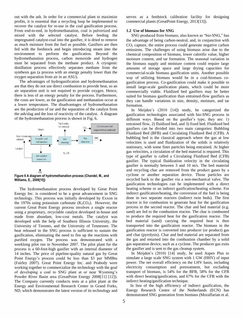
control over the final product gas composition. Figure 9 shows
the process configuration involving SHR gasification to
produce syngas with a high methane content. The slurry made
of the carbonaceous feed (coal) and water, along with the
recycled hydrogen are fed to the SHR, operating at
approximately 850 ºC and 400 psi.
Figure 9. Schematic diagram of a steam hydrogasification reactor (SHR) method to produce high CH4 production (Chan and Norbeck, 2009 [21])
The SHR generates a high methane content product gas that
is subjected to warm gas cleanup in order to remove
contaminants such as sulfur. The gas cleanup must be
performed at a temperature above the dew point of water. This
will allow the unreacted steam from the SHR to be directly fed
into the shift reactor along with the product gas. In this case, the
shift reactor will be operated as a ‘sour-shift’ reactor with a
sulfur tolerant catalyst. In the shift reactor, the CO present in
the clean product gas reacts with the steam to produce H2.
Methane is inert in the shift reactor. Alternatively, the product
gas will be cooled down and H2 can be recycled to the SHR as
feed. The recycled hydrogen stream eliminates the hydrogen
supply problem. The final product gas in either case contains a
high quantity of methane. The experimental results of the steam
hydrogasification of coal and wood mixtures in a batch reactor
are presented by Chan and Norbeck (2009) [21]). Their results
show that the carbon conversion values at 700 ºC were
approximately 60%, whereas, at 800 ºC, the values were closer
to 80%. Their simulation results show that the product gas from
an SHR gasifier contains considerable amounts of methane.
The concentration of methane increases with decreasing
H2O/Feed mass ratio and increasing H2/C feed mole ratio.
Operating at higher pressures also favors an increase in
methane production.
Tunå (2008) [22] evaluated twelve different systems for
production of SNG by using Aspen Plus. The system consists
of three gasifiers: an entrained-flow, fluidiszd-bed, and indirect
gasifier. Both an isothermal methanation process and an
adiabatic methanation process have been modeled. Gas cleanup
was performed using both conventional zinc oxide
desulfurization with PSA upgrade and a Rectisol® wash. The
simulation results show that SNG efficiencies from biomass to
methane of 50% are possible with either gasifier. The fluidized-
bed and indirect gasifiers were able to produce SNG with an
efficiency around 67%. Furthermore, utilizing a Rectisol gas
cleanup system does not have a significant negative impact on
SNG efficiency, but it affects overall efficiency. The simplest
system—zinc oxide desulphurization with PSA gas cleanup—
coupled with either methanation system is considered by Tuna
as the most promising choice. It is based on well-established,
widely-used equipment and it offers better efficiency than a
wet-gas cleanup process such as Rectisol. If there is a
significant amount of sulfur in the gas stream that needs to be
removed, or if the carbon dioxide needs to be captured and
removed, the Rectisol method will become a competitive option.
Typically, carbon dioxide capture is not necessary for biomass-
based plants as the carbon emissions are considered neutral.
Chen et al. (2009) [23] reviewed the state-of-the-art
technologies for Coal-to-SNG, conducted a thermodynamic
parametric study of the main components in this process, and
and also made an efficiency assessment of the overall energy
system, implementing different gasification technologies,
including the hydromethanation process. Their results show the
O2/Carbon ratio to be about 0.25 - 0.3 and the H2O/Carbon ratio
to be about 1.5 – 2, which are favorable ranges to produce a
CH4-rich syngas with a high H2/CO ratio. Higher pressure is
favorable to the hydromethanation reaction and increases
methane yield. The analysis shows that moving-bed, dry ash
gasification achieves a higher energy conversion efficiency
(67%) than entrained flow gasification (57%) for the overall
Coal-to-SNG process. Hydromethanation is a promising route
with about 70% energy efficiency. However, it is still under
development because of the challenges for separating the
catalyst from the ash/slag and recovering the loss of reactivity
of the catalyst.
Chandel and Williams (2009) [24] examined the different
technologies for producing SNG, as well as the production
costs and the environmental impacts of SNG. Their paper
identified the conditions under which SNG production could be
economically viable. In a low‐carbon economy, the
development of the carbon capture and storage would be one of
the critical factors in the future development of SNG. In the
absence of carbon capture and storage and carbon allowance
price in the future, the SNG could be expensive and may not be
economically viable. Higher natural gas prices and the selling
of CO2 to enhance oil recovery could make SNGs economically
viable. The levelized cost of producing SNG is $8.42/MMBtu
for plants using bituminous coal and $9.53/MMBtu for those
using sub‐bituminous coal. With CO2 sequestration, SNG costs
would increase to $9.15/MMBtu for bituminous coals and
8
$10.55/MMBtu for sub‐bituminous coals. They also examined
the cost of producing Bio‐SNG and they reported that, for
keeping the bio‐SNG price lower than $12/MMBtu, the
biomass price should not exceed $2.2/MMBtu. The cost of
producing SNG ($8.42-9.53/MMBtu) provided by the analysis
of Chandel and Williams (2009) [24] is much more expensive
than that ($5/MMBtu) taken from the NETL's report (2008)
mentioned earlier. This further exemplifies the uncertainty in
evaluating the true production cost of SNG.
1.4 Methanation reaction rates
The tail end of an SNG plant must necessarily employ a
catalytic methanation step in order to upgrade the heating value
to approximately 950 Btu/SCF. This step typically involves the
methanation reaction shown in Equation 8.1, which is
accompanied by a relatively high heat of reaction (HR = 49.3
kcal/mol). Although the methanation of trace quantities of CO
has been practiced commercially for many years in ammonia
plants, SNG methanation from coal poses a more severe
problem due to the high concentrations of CO in the synthesis
gas. With nickel methanation catalysts, the reaction rates are
relatively high, and, consequently, heat is also liberated at very
high rates. Problems connected with localized coking and
catalyst sintering generally lead to reactor design concepts
which employ high recycle ratios as first suggested by Dent et
al. (1948) [25]. Since the catalyst is always in contact with a
reacting gas mixture, which contains all or most of the five
components involved in methanation synthesis: H2, CO, CO2,
H2O, and CH4, Saletore and Thomson (1977) [26] decided to
conduct an experimental study to determine the methanation
reaction rates for synthesis feeds containing all five components.
They also investigated the effect of steam’s high partial
pressures on the methanation reaction rate. This was motivated
by the fact that steam may be added to the synthesis gas in
order to inhibit carbon deposition and at least one methanation
reactor’s design concept utilizes a large excess of steam ( Dent
et al., 1948) [25].
Early work on methanation kinetics was accomplished at the
University of Michigan (Akers and White, 1948) utilizing a 3.2
mm commercial nickel catalyst. They correlated their results by
assuming that the rate-determining steps were surface reactions,
although there was some evidence of strong pore diffusion
effects. utilized CO2 in place of CO and found that the rate of
CO2 methanation, CO2 +4H2 CH4 + 2H2O (HR = 165
MJ/kmol), was two orders of magnitude less than the CO
methanation rate. Schoubye (1969,) [27] employed small-
sized nickel catalysts at high pressures and concluded that the
reaction order with respect to CO was -0.5 at high CO
concentration (over 20%) and that the data was best correlated
by assuming that H2 adsorption determined the reaction rate.
Negative reaction orders with respect to CO were also found by
Betta et al. (1974) [28] and Vannice (1975) [29], although
they all worked at pressures of 1 atm or less. Saletore and
Thomson (1977) [30] conducted the measurements of the
methanation reaction rate with a 1.6-mm nickel catalyst
utilizing feed compositions typical of recycle reaction
configurations and product streams with a high CO2 content.
The apparent reaction orders for hydrogen and steam were
found to be 0.85 and -0.9 respectively, but there was no
significant dependency of the methanation rate on the carbon
oxides. Rostrup-Nielsen, et al. (2007) [31] investigated the
high temperature methanation sintering and structure sensitivity
by doing experiments and found that high temperature
methanation plays a role in the manufacture of SNGs. The key
problem is resistance to sintering, which results in a decrease of
both the metal surface area and the specific activity. Paraskevi,
et al. (2008) [32] investigated the catalytic performance of
Al2O3-supported noble metal catalysts for the methanation of
CO, CO2, and their mixture with respect to the nature of the
dispersed metallic phase (Ru, Rh, Pt, Pd). Results show that the
catalytic performance, apparent activation energy, and
selectivity of reaction products for the solo- or co-methanation
of CO/CO2 depend strongly on the nature of the metallic phase.
Generally, methanation activity is much higher for Ruthenium
and Rhodium catalysts, compared to Palladium or Platinum,
which tend to enhance the WGS reaction.
For the simulations in the other chapters of this dissertation,
the methanation reactions have been excluded due to low
methane production in the previously studied gasification
process. However, for this chapter, since it has improved, the
simulation will focus on modeling the methanation reactions in
the coal gasification process.
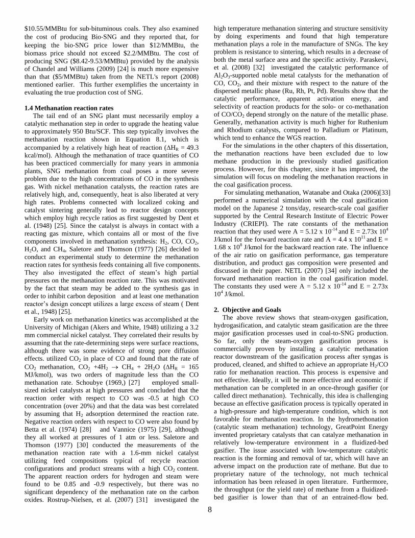
For simulating methanation, Watanabe and Otaka (2006)[33]
performed a numerical simulation with the coal gasification
model on the Japanese 2 tons/day, research-scale coal gasifier
supported by the Central Research Institute of Electric Power
Industry (CRIEPI). The rate constants of the methanation
reaction that they used were A = 5.12 x 10⁻¹⁴ and E = 2.73x 10⁴
J/kmol for the forward reaction rate and A = 4.4 x 10¹¹ and E =
1.68 x 10⁸ J/kmol for the backward reaction rate. The influence
of the air ratio on gasification performance, gas temperature
distribution, and product gas composition were presented and
discussed in their paper. NETL (2007) [34] only included the
forward methanation reaction in the coal gasification model.
The constants they used were A = 5.12 x 10⁻¹⁴ and E = 2.73x
104 J/kmol.
2. Objective and Goals
The above review shows that steam-oxygen gasification,
hydrogasification, and catalytic steam gasification are the three
major gasification processes used in coal-to-SNG production.
So far, only the steam-oxygen gasification process is
commercially proven by installing a catalytic methanation
reactor downstream of the gasification process after syngas is
produced, cleaned, and shifted to achieve an appropriate H2/CO
ratio for methanation reaction. This process is expensive and
not effective. Ideally, it will be more effective and economic if
methanation can be completed in an once-through gasifier (or
called direct methanation). Technically, this idea is challenging
because an effective gasification process is typically operated in
a high-pressure and high-temperature condition, which is not
favorable for methanation reaction. In the hydromethonation
(catalytic steam methanation) technology, GreatPoint Energy
invented proprietary catalysts that can catalyze methanation in
relatively low-temperature environment in a fluidized-bed
gasifier. The issue associated with low-temperature catalytic
reaction is the forming and removal of tar, which will have an
adverse impact on the production rate of methane. But due to
proprietary nature of the technology, not much technical
information has been released in open literature. Furthermore,
the throughput (or the yield rate) of methane from a fluidized-
bed gasifier is lower than that of an entrained-flow bed.
9
Therefore, one of the objectives of this study is to investigate
the methanation process in an entrained-flow gasifier instead of
a fluidized-bed gasifier at higher-temperature environment
without tar formation.
Since methanation is a reversible catalytic reaction, most of
the reaction rates for the methanation reaction were obtained
from experiments with specific catalysts under laboratory
conditions of relatively narrow ranges of pressure and
temperature. However, the pressure and temperature conditions
are very different than the operating conditions in an entrained-
flow coal gasifier. Therefore, it is not clear how the published
reaction rates can be trustfully used to predict the actual
methanation reaction rate in a gasifier without the presence of
catalysts and under different temperature and pressure
conditions than those used in the laboratory. This challenge is
further compounded by the fact that inherent minerals in coal
ashes can also affect the methanation kinetics. Therefore, due
to the unavailability of appropriate methanation reaction rates
for broad operating conditions with different types of coals in
actual gasifiers without using catalysts, the primary objective of
this study is to use computational model as a convenient tool to
investigate the sensitivity of methane production under a wide
range methanation reaction rates from non-catalytic condition
with A in the order of 10-14 to catalytic condition with A in the
order of 1011.
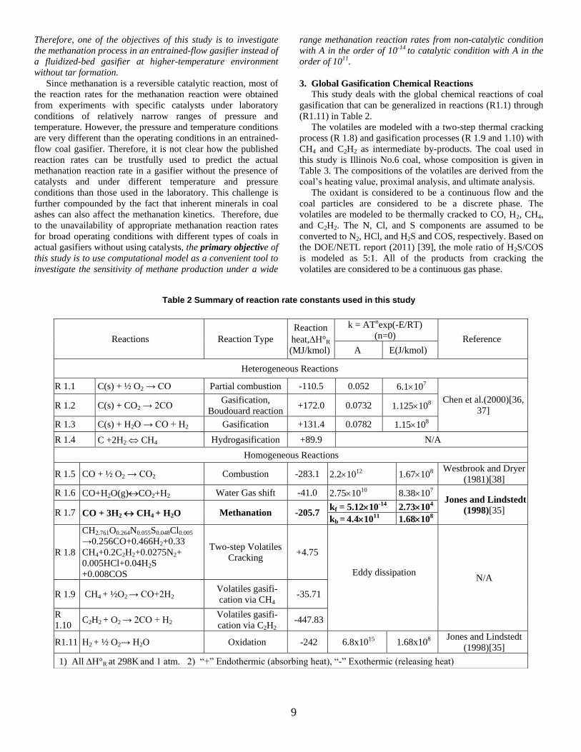
3. Global Gasification Chemical Reactions
This study deals with the global chemical reactions of coal
gasification that can be generalized in reactions (R1.1) through
(R1.11) in Table 2.
The volatiles are modeled with a two-step thermal cracking
process (R 1.8) and gasification processes (R 1.9 and 1.10) with
CH4 and C2H2 as intermediate by-products. The coal used in
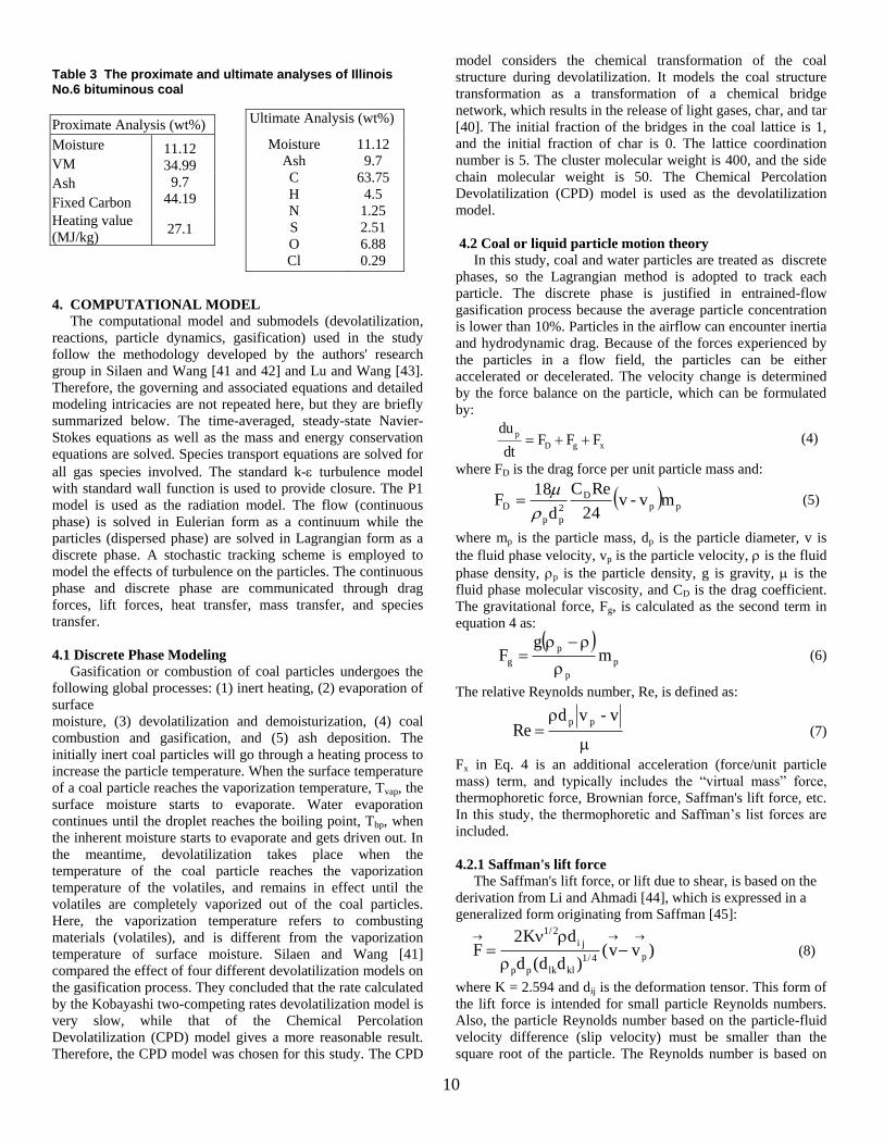
this study is Illinois No.6 coal, whose composition is given in
Table 3. The compositions of the volatiles are derived from the
coal’s heating value, proximal analysis, and ultimate analysis.
The oxidant is considered to be a continuous flow and the
coal particles are considered to be a discrete phase. The
volatiles are modeled to be thermally cracked to CO, H2, CH4,
and C2H2. The N, Cl, and S components are assumed to be
converted to N2, HCl, and H2S and COS, respectively. Based on
the DOE/NETL report (2011) [39], the mole ratio of H2S/COS
is modeled as 5:1. All of the products from cracking the
volatiles are considered to be a continuous gas phase.
Table 2 Summary of reaction rate constants used in this study
Reactions Reaction Type
Reaction
heat,H°R
(MJ/kmol)
k = ATnexp(-E/RT)
(n=0) Reference
A E(J/kmol)
Heterogeneous Reactions
R 1.1 C(s) + ½ O2 → CO Partial combustion -110.5 0.052 6.1107
Chen et al.(2000)[36,
37] R 1.2 C(s) + CO2 → 2CO
Gasification,
Boudouard reaction +172.0 0.0732 1.125108
R 1.3 C(s) + H2O → CO + H2 Gasification +131.4 0.0782 1.15108
R 1.4 C +2H2 CH4 Hydrogasification +89.9 N/A
Homogeneous Reactions
R 1.5 CO + ½ O2 → CO2 Combustion -283.1 2.21012 1.67108 Westbrook and Dryer
(1981)[38]
R 1.6 CO+H2O(g)CO2+H2 Water Gas shift -41.0 2.751010 8.38107 Jones and Lindstedt
(1998)[35] R 1.7 CO + 3H2 CH4 + H2O Methanation -205.7 kf = 5.1210
-14 2.7310
4
kb = 4.41011
1.68108
R 1.8
CH2.761O0.264N0.055S0.048Cl0.005
→0.256CO+0.466H2+0.33
CH4+0.2C2H2+0.0275N2+
0.005HCl+0.04H2S
+0.008COS
Two-step Volatiles
Cracking +4.75
Eddy dissipation
N/A
R 1.9 CH4 + ½O2 → CO+2H2 Volatiles gasifi-
cation via CH4 -35.71
R
1.10 C2H2 + O2 → 2CO + H2
Volatiles gasifi-
cation via C2H2 -447.83
R1.11 H2 + ½ O2→ H2O Oxidation -242 6.8x10¹⁵ 1.68x10⁸ Jones and Lindstedt
(1998)[35]
1) All H°R at 298K and 1 atm. 2) “+” Endothermic (absorbing heat), “-” Exothermic (releasing heat)
10
Table 3 The proximate and ultimate analyses of Illinois No.6 bituminous coal
4. COMPUTATIONAL MODEL
The computational model and submodels (devolatilization,
reactions, particle dynamics, gasification) used in the study
follow the methodology developed by the authors' research
group in Silaen and Wang [41 and 42] and Lu and Wang [43].
Therefore, the governing and associated equations and detailed
modeling intricacies are not repeated here, but they are briefly
summarized below. The time-averaged, steady-state Navier-
Stokes equations as well as the mass and energy conservation
equations are solved. Species transport equations are solved for
all gas species involved. The standard k- turbulence model
with standard wall function is used to provide closure. The P1
model is used as the radiation model. The flow (continuous
phase) is solved in Eulerian form as a continuum while the
particles (dispersed phase) are solved in Lagrangian form as a
discrete phase. A stochastic tracking scheme is employed to
model the effects of turbulence on the particles. The continuous
phase and discrete phase are communicated through drag
forces, lift forces, heat transfer, mass transfer, and species
transfer.
4.1 Discrete Phase Modeling
Gasification or combustion of coal particles undergoes the
following global processes: (1) inert heating, (2) evaporation of
surface
moisture, (3) devolatilization and demoisturization, (4) coal
combustion and gasification, and (5) ash deposition. The
initially inert coal particles will go through a heating process to
increase the particle temperature. When the surface temperature
of a coal particle reaches the vaporization temperature, Tvap, the
surface moisture starts to evaporate. Water evaporation
continues until the droplet reaches the boiling point, Tbp, when
the inherent moisture starts to evaporate and gets driven out. In
the meantime, devolatilization takes place when the
temperature of the coal particle reaches the vaporization
temperature of the volatiles, and remains in effect until the
volatiles are completely vaporized out of the coal particles.
Here, the vaporization temperature refers to combusting
materials (volatiles), and is different from the vaporization
temperature of surface moisture. Silaen and Wang [41]
compared the effect of four different devolatilization models on
the gasification process. They concluded that the rate calculated
by the Kobayashi two-competing rates devolatilization model is
very slow, while that of the Chemical Percolation
Devolatilization (CPD) model gives a more reasonable result.
Therefore, the CPD model was chosen for this study. The CPD
model considers the chemical transformation of the coal
structure during devolatilization. It models the coal structure
transformation as a transformation of a chemical bridge
network, which results in the release of light gases, char, and tar
[40]. The initial fraction of the bridges in the coal lattice is 1,
and the initial fraction of char is 0. The lattice coordination
number is 5. The cluster molecular weight is 400, and the side
chain molecular weight is 50. The Chemical Percolation
Devolatilization (CPD) model is used as the devolatilization
model.
4.2 Coal or liquid particle motion theory
In this study, coal and water particles are treated as discrete
phases, so the Lagrangian method is adopted to track each
particle. The discrete phase is justified in entrained-flow
gasification process because the average particle concentration
is lower than 10%. Particles in the airflow can encounter inertia
and hydrodynamic drag. Because of the forces experienced by
the particles in a flow field, the particles can be either
accelerated or decelerated. The velocity change is determined
by the force balance on the particle, which can be formulated
by:
xgD
pFFF
dt
du (4)
where FD is the drag force per unit particle mass and:
pp
D
2
pp
D mv-v24
ReC
d
18F
(5)
where mp is the particle mass, dp is the particle diameter, v is
the fluid phase velocity, vp is the particle velocity, is the fluid
phase density, p is the particle density, g is gravity, is the
fluid phase molecular viscosity, and CD is the drag coefficient.
The gravitational force, Fg, is calculated as the second term in
equation 4 as:
p
p
p
g mg
F
(6)
The relative Reynolds number, Re, is defined as:
v-vdRe
pp (7)
Fx in Eq. 4 is an additional acceleration (force/unit particle
mass) term, and typically includes the “virtual mass” force,
thermophoretic force, Brownian force, Saffman's lift force, etc.
In this study, the thermophoretic and Saffman’s list forces are
included.
4.2.1 Saffman's lift force
The Saffman's lift force, or lift due to shear, is based on the
derivation from Li and Ahmadi [44], which is expressed in a
generalized form originating from Saffman [45]:
)vv()dd(d
dK2F p4/1
kllkpp
ji
2/1
(8)
where K = 2.594 and dij is the deformation tensor. This form of
the lift force is intended for small particle Reynolds numbers.
Also, the particle Reynolds number based on the particle-fluid
velocity difference (slip velocity) must be smaller than the
square root of the particle. The Reynolds number is based on
Proximate Analysis (wt%)
Moisture 11.12
34.99
9.7
44.19
VM
Ash
Fixed Carbon
Heating value
(MJ/kg) 27.1
Ultimate Analysis (wt%)
Moisture
Ash
C
H
N
S
O
Cl
11.12
9.7
63.75
4.5
1.25
2.51
6.88
0.29

11
the shear field. In this study, Saffman's lift force reaches about
30% of Fg, so it is included in the particle motion model.
4.2.2 Thermophoretic Force
When a particle exists in a flow field with temperature
gradients, the force that arises on the particle due to this
temperature gradient is called the thermophoretic force. This
force is caused by the unequal momentum between the particle
and the fluid. The higher molecular velocities on one side of the
particle due to the higher temperature give rise to more
momentum exchange and a resulting force in the direction of
decreasing temperature. An extensive review of thermophoresis
by Talbot et al. [46] indicated that the following equation for
the thermophoretic force, Fx, provides the best fit with
experimental data over a wide range of Knudsen numbers:
x
T
Tm
1
)KnC2K21)(KnC31(
)KnCK(Cd6F
ptm
ts
2
p
x
(9)
where
Kn = Knudsen number = 2λ/dp
λ = mean free path of the fluid
K = k/kp
k = fluid thermal conductivity based on translational energy
only = (15/4) µR
kp = particle thermal conductivity
CS = 1.17, Ct = 2.18, Cm = 1.14
mp = particle mass
T = local fluid temperature
µ= fluid viscosity
This expression assumes that the particle is a sphere and that
the fluid is an ideal gas. In this study, the local temperature
gradient in the flow field is important because of local
combustion and gasification reactions between the coal
particles and gas mixture. Therefore, the thermophoretic force
is considered in this study.
4.3 Liquid particle model
When the coal is injected through the injectors, the water
content in the coal (for dry-feed cases) and the water used for
slurry-feed cases is treated as being in the condensed phase (i.e.
liquid water), which can't be lumped into the continuous phase,
so the liquid water is atomized into small droplets.
Theoretically, evaporation occurs at two stages: (a) when the
temperature is higher than the saturation temperature (based on
the local water vapor concentration,) water evaporates from the
droplet’s surface, and the evaporation is controlled by the water
vapor partial pressure until 100% relative humidity is achieved;
and (b) when the boiling temperature (determined by the gas-
water mixture pressure) is reached, water continues to
evaporate even though the relative humidity reaches 100%.
After the moisture is evaporated due to either high temperature
or low moisture partial pressure, the vapor diffuses into the
main flow and is transported away. The rate of vaporization is
governed by the concentration difference between the surface
and the gas stream, and the corresponding mass change rate of
the droplet can be given by:
(10)
where kc is the mass transfer coefficient and Cs is the
concentration of the vapor at the particle’s surface, which is
evaluated by assuming that the flow over the surface is
saturated. C is the vapor concentration of the bulk flow,
obtained by solving the transport equations. The values of kc
can be calculated from empirical correlations by Ranz and
Marshall (1952) [47],
(11)
where Sh is the Sherwood number, Sc is the Schmidt number
(defined as /D), D is the diffusion coefficient of vapor in the
bulk flow. Red is the Reynolds number, defined as u/d, u is
the slip velocity between the particle and the gas, and d is the
particle diameter.
When the particle temperature reaches the boiling point, the
following equation can be used to evaluate its evaporation rate:
(12)
where is the heat conductivity of the gas/air, and hfg is the
droplet latent heat. cp is the specific heat of the bulk flow.
The particle temperature can also be changed due to heat
transfer between particles and the continuous phase. The
particle’s sensible heat changes depending on the convective
heat transfer, latent heat (hfg), species reaction heat (Hreac), and
radiation, as shown in the following equation:
(13)
where the convective heat transfer coefficient (h) can be
obtained with a similar empirical correlation to Eq. 14:
(14)
where Nu is the Nusselt number, and Pr is the Prandtl number.
Eq. (12) is used for both water droplets and coal particles.
4.4 Particle Reactions
The reactions of the particles occur after the devolatilization
process has finished. The rate of depletion of solid due to a
surface reaction is expressed as:
RAηR (15)
where
R = rate of particle surface species depletion (kg/s)
A = particle surface area (m2)
Y = mass fraction of the solid species on the surface of the
particle
= effectiveness factor (dimensionless)
R = rate of particle surface species reaction per unit area
(kg/m2-s)
pn = bulk concentration of the gas phase species (kg/m3)
D = diffusion rate coefficient for reaction
k = kinetic reaction rate constant (units vary)
N = apparent order of reaction.
The particle reaction rate, R, is controlled by the diffusion of
reactant gases (e.g., O2, CO2, H2, and water vapor) from the
immediate continuous phase in the very cell, where the particle
is located, to the particle's surface; it can be expressed as
)C(Ckπddt
dmsc
2d
0.330.5d
cd Sc0.6Re2.0
D
dkSh
pfgp
0.5
d
2d c/h/)TT(c1ln)0.46Re(2.0d
λπd
dt
dm
44p
fg
p
ppdt
dmh
dt
dm T)-h(T
dt
dTcm TAHfA Rppreachp
33.05.0dd PrRe6.00.2
λ
hdNu
12
R = D (pn- ps) = kpsN (16)
where pn is the gas concentration surrounding the particle and ps
is the gas concentration at the particle surface, and k is the
kinetic reaction rate constant. However, since ps is not known,
ps is then expressed as ps= pg - (R/D), so the explicit
appearance of ps can be removed by plugging ps into the above
equation, resulting in the following equation,
N
nD
RpkR
(17)
The kinetic reaction rate constant is usually defined in an
Arrhenius form as
RTEneATk . (18)
The second term in Eq. (17) indicates the diffusion limit
condition that controls the surface chemical reaction rate, k. In
Eq. (17) R needs to be obtained by iterations. However, for
reaction order N = 1, R can be solved explicitly as
pn[kD/(D+k)], and the rate of particle surface species depletion
can be expressed as
kD
kDpAηR n
. (19)
For reaction order N = 0,
kAηR . (20)
The unit of the rate of depletion of the solid R is kg/s. The
kinetic reaction rate constant k (kg/m2-s) for the solid-gas char
reactions are determined by the kinetic reaction rate constants
adopted from published literatures as presented in Table 2.
4.5 Turbulent Dispersion of Particles
The dispersion of particles due to turbulence in the fluid
phase is predicted by using a stochastic tracking scheme, which
is modeled with the eddy lifetime. In this model, each eddy is
characterized by the Gaussian-distributed, random velocity
fluctuations u' , v' , w' , and a time scalee . Therefore, the
particle trajectories are calculated by using the instantaneous
flow velocity (u) rather than the average velocity ( ). The
velocity fluctuation is then given as: u = + u' and
0.50.5
2 2k/3ζu'ζu'
(21)
where is a normally distributed random number. This velocity
will apply during a characteristic lifetime of the eddy (te),
calculated from the turbulence kinetic energy and dissipation
rate. After this time period, the instantaneous velocity will be
updated with a new value until a full trajectory is obtained.
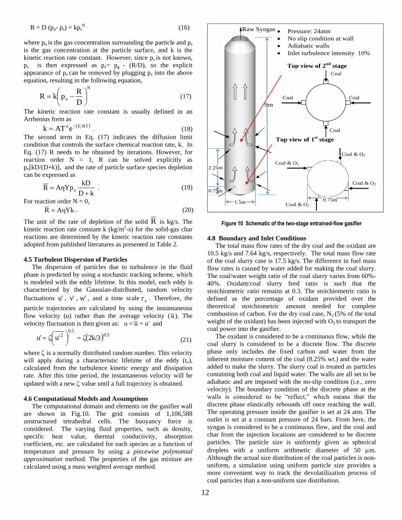
4.6 Computational Models and Assumptions
The computational domain and elements on the gasifier wall
are shown in Fig.10. The grid consists of 1,106,588
unstructured tetrahedral cells. The buoyancy force is
considered. The varying fluid properties, such as density,
specific heat value, thermal conductivity, absorption
coefficient, etc. are calculated for each species as a function of
temperature and pressure by using a piecewise polynomial
approximation method. The properties of the gas mixture are
calculated using a mass weighted average method.
Top view of 1st stage
injectors
Top view of 2nd
stage
injectors
Pressure: 24atm
No slip condition at wall
Adiabatic walls
Inlet turbulence intensity 10%
Coal Coal
Coal & O2
Coal & O2
Coal & O2
Coal & O2
9m
1.5m
0.75m
2.25m
Raw Syngas
0.75m
0.75m
Coal
Coal
Figure 10 Schematic of the two-stage entrained-flow gasifier
4.8 Boundary and Inlet Conditions
The total mass flow rates of the dry coal and the oxidant are
10.5 kg/s and 7.64 kg/s, respectively. The total mass flow rate
of the coal slurry case is 17.5 kg/s. The difference in fuel mass
flow rates is caused by water added for making the coal slurry.
The coal/water weight ratio of the coal slurry varies from 60%-
40%. Oxidant/coal slurry feed ratio is such that the
stoichiometric ratio remains at 0.3. The stoichiometric ratio is
defined as the percentage of oxidant provided over the
theoretical stoichiometric amount needed for complete
combustion of carbon. For the dry coal case, N2 (5% of the total
weight of the oxidant) has been injected with O2 to transport the
coal power into the gasifier. The oxidant is considered to be a continuous flow, while the
coal slurry is considered to be a discrete flow. The discrete
phase only includes the fixed carbon and water from the
inherent moisture content of the coal (8.25% wt.) and the water
added to make the slurry. The slurry coal is treated as particles
containing both coal and liquid water. The walls are all set to be
adiabatic and are imposed with the no-slip condition (i.e., zero
velocity). The boundary condition of the discrete phase at the
walls is considered to be “reflect,” which means that the
discrete phase elastically rebounds off once reaching the wall.
The operating pressure inside the gasifier is set at 24 atm. The
outlet is set at a constant pressure of 24 bars. From here, the
syngas is considered to be a continuous flow, and the coal and
char from the injection locations are considered to be discrete
particles. The particle size is uniformly given as spherical
droplets with a uniform arithmetic diameter of 50 m.
Although the actual size distribution of the coal particles is non-
uniform, a simulation using uniform particle size provides a
more convenient way to track the devolatilization process of
coal particles than a non-uniform size distribution.
13
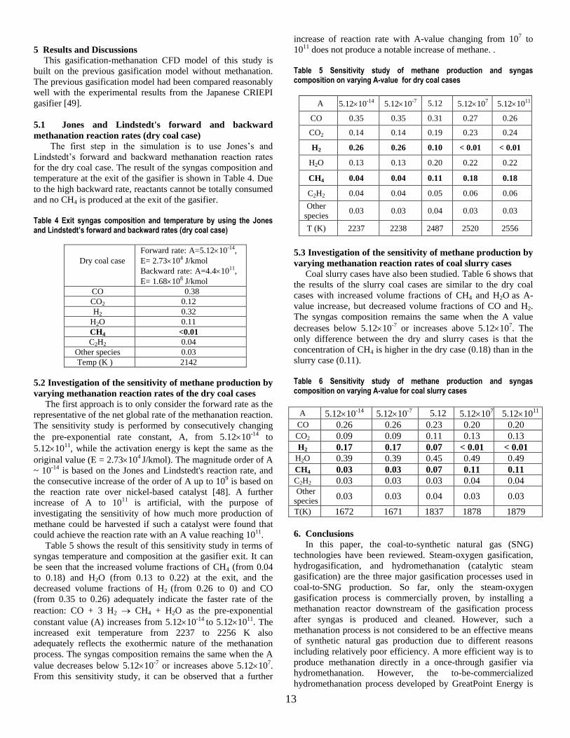
5 Results and Discussions
This gasification-methanation CFD model of this study is
built on the previous gasification model without methanation.
The previous gasification model had been compared reasonably
well with the experimental results from the Japanese CRIEPI
gasifier [49].
5.1 Jones and Lindstedt's forward and backward
methanation reaction rates (dry coal case)
The first step in the simulation is to use Jones’s and
Lindstedt’s forward and backward methanation reaction rates
for the dry coal case. The result of the syngas composition and
temperature at the exit of the gasifier is shown in Table 4. Due
to the high backward rate, reactants cannot be totally consumed
and no CH4 is produced at the exit of the gasifier.
Table 4 Exit syngas composition and temperature by using the Jones and Lindstedt’s forward and backward rates (dry coal case)
Dry coal case
Forward rate: A=5.1210-14,
E= 2.73104 J/kmol
Backward rate: A=4.41011,
E= 1.68108 J/kmol
CO 0.38
CO2 0.12
H2 0.32
H2O 0.11
CH4 <0.01
C2H2 0.04
Other species 0.03
Temp (K ) 2142
5.2 Investigation of the sensitivity of methane production by
varying methanation reaction rates of the dry coal cases
The first approach is to only consider the forward rate as the
representative of the net global rate of the methanation reaction.
The sensitivity study is performed by consecutively changing
the pre-exponential rate constant, A, from 5.1210-14 to
5.121011, while the activation energy is kept the same as the
original value (E = 2.73104 J/kmol). The magnitude order of A
~ 10-14 is based on the Jones and Lindstedt's reaction rate, and
the consecutive increase of the order of A up to 109 is based on
the reaction rate over nickel-based catalyst [48]. A further
increase of A to 1011 is artificial, with the purpose of
investigating the sensitivity of how much more production of
methane could be harvested if such a catalyst were found that
could achieve the reaction rate with an A value reaching 1011.
Table 5 shows the result of this sensitivity study in terms of
syngas temperature and composition at the gasifier exit. It can
be seen that the increased volume fractions of CH4 (from 0.04
to 0.18) and H2O (from 0.13 to 0.22) at the exit, and the
decreased volume fractions of H2 (from 0.26 to 0) and CO
(from 0.35 to 0.26) adequately indicate the faster rate of the
reaction: CO + 3 H2 CH4 + H2O as the pre-exponential
constant value (A) increases from 5.1210-14 to 5.121011. The
increased exit temperature from 2237 to 2256 K also
adequately reflects the exothermic nature of the methanation
process. The syngas composition remains the same when the A
value decreases below 5.1210-7 or increases above 5.12107.
From this sensitivity study, it can be observed that a further
increase of reaction rate with A-value changing from 107 to
1011 does not produce a notable increase of methane. .
Table 5 Sensitivity study of methane production and syngas composition on varying A-value for dry coal cases
A 5.1210-14 5.1210-7 5.12 5.12107 5.121011
CO 0.35 0.35 0.31 0.27 0.26
CO2 0.14 0.14 0.19 0.23 0.24
H2 0.26 0.26 0.10 < 0.01 < 0.01
H2O 0.13 0.13 0.20 0.22 0.22
CH4 0.04 0.04 0.11 0.18 0.18
C2H2 0.04 0.04 0.05 0.06 0.06
Other
species 0.03 0.03 0.04 0.03 0.03
T (K) 2237 2238 2487 2520 2556
5.3 Investigation of the sensitivity of methane production by
varying methanation reaction rates of coal slurry cases
Coal slurry cases have also been studied. Table 6 shows that
the results of the slurry coal cases are similar to the dry coal
cases with increased volume fractions of CH4 and H2O as A-
value increase, but decreased volume fractions of CO and H2.
The syngas composition remains the same when the A value
decreases below 5.1210-7 or increases above 5.12107. The
only difference between the dry and slurry cases is that the
concentration of CH4 is higher in the dry case (0.18) than in the
slurry case (0.11).
Table 6 Sensitivity study of methane production and syngas composition on varying A-value for coal slurry cases
6. Conclusions
In this paper, the coal-to-synthetic natural gas (SNG)
technologies have been reviewed. Steam-oxygen gasification,
hydrogasification, and hydromethanation (catalytic steam
gasification) are the three major gasification processes used in
coal-to-SNG production. So far, only the steam-oxygen
gasification process is commercially proven, by installing a
methanation reactor downstream of the gasification process
after syngas is produced and cleaned. However, such a
methanation process is not considered to be an effective means
of synthetic natural gas production due to different reasons
including relatively poor efficiency. A more efficient way is to
produce methanation directly in a once-through gasifier via
hydromethanation. However, the to-be-commercialized
hydromethanation process developed by GreatPoint Energy is
A 5.1210-14 5.1210-7 5.12 5.12107 5.121011
CO 0.26 0.26 0.23 0.20 0.20
CO2 0.09 0.09 0.11 0.13 0.13
H2 0.17 0.17 0.07 < 0.01 < 0.01
H2O 0.39 0.39 0.45 0.49 0.49
CH4 0.03 0.03 0.07 0.11 0.11
C2H2 0.03 0.03 0.03 0.04 0.04 Other
species 0.03 0.03 0.04 0.03 0.03
T(K) 1672 1671 1837 1878 1879

14
using low-temperature catalytic steam methanation in fluidized
beds. To avoid tar forming and increase throughput, this study
investigates methanation process in a high-pressure and high-
temperature entrained-flow gasifier through CFD simulation.
Since both the non-catalytic and catalytic reaction rates for
methanation are not actually known in a complicated and
hazardous environment such as in an entrained-flow gasifier, a
CFD scheme is used in this study as a convenient tool to
investigate the sensitivity of methane production on the
variation of the methanation reaction rates. The sensitivity
study is performed by keeping the activation energy of Jones
and Lindstedt's rates intact but changing the pre-exponential
constant value, A, from non-catalytic condition in the order of
10-7 to catalytic condition in the order of 1011. Both dry-feed
and slurry-feed conditions have been considered. The results
show that the syngas composition remains the same when the
A-value decreases below 5.1210-7 or increases above
5.12107. From this sensitivity study, it can be observed that a
further increase of reaction rate with A-value changing from
107 to 1011 does not produce a notable increase of methane
above 18% (vol.) for dry-feed cases and 11% for slurry-feed
cases. This SNG production limit could be caused by the high-
temperature and short residence time (3- 4 seconds) in the
entrained-flow gasifier.
References
1. Chandel, M., and Williams, E., 2009, “Synthetic Natural
Gas (SNG): Technology, Environmental Implications, and
Economics,” Climate Change Policy Partnership.
http://www. netldev netl.doe.gov.
2. DOE/NETL Report, 2007, “Industrial Size Gasification for
Syngas, Substitute Natural Gas and Power Production,”
National Energy Technology Laboratory.
3. Chen, L., Nolan, R., and Avadhany, S., 2009,
"Thermodynamic Analysis of Coal to Synthetic Natural Gas
Process,”http://www.mit.edu/people/leichen/Thermodynami
c_Analysis_of_the_coal_to_SNG_process.pdf
4. Hohlein, B.; Niessen, H.; Range, J.; Schiebahn, H. J. R.;
Vorwerk, M., “Methane from synthesi s gas and operation
of high-temperature methanation”. Nuclear Engineering
and Design 1984, 78, (2), 241-250.
5. DOE Report, 2006, “Practical Experience Gained during
the First Twenty Years of Operation of the Great Plains
Gasification Plant and Implications for Future Projects,”
Department of Energy.
6. Ruby, J., Kramer, S., Hobbs, R., and Bryan B., 2008.
Substitute Natural Gas from Coal Co‐Production Project – a
Status Report. http://www.nexant.com/docs/Service
/energy_technology/SNG.pdf.
7. Higman, C., and M. van der Burgt, Gasification, Elsevier,
2003.
8. Walker, P., Rusinko, F., Austin, L., 1959, "Gas reactions of
carbon," Advances in Catalysis, vol. 11, pp. 133-221.
9. Probstein, R., Hicks, R., 1982, Synthetic fuels. McGraw-
Hill, New York.
10. Chandel, M., and Williams, E., 2009, “Synthetic Natural
Gas (SNG): Technology, Environmental Implications, and
Economics,” Climate Change Policy Partnership.
http://www. netldev netl.doe.gov.
11. GreatPoint energy, 2008a. http://www.greatpointenergy.com.
12. GreatPoint Energy, 2008b. “GreatPoint Energy announces
coal supply partnership with Peabody Energy and enters
into agreement to build natural gas manufacturing facilities
in Powder River,” Basin. http://www.greatpointenergy.
com/ GPE‐Peabody1‐25‐08.pdf.
13. GreatPoint Energy, 2015,
https://www.greatpointenergy.com/developmentstatus.php
14. C.M. van der Meijden, 2010, “Development of the
MILENA Gasification Technology for the Production of
Bio-SNG,” Eindhoven University of Technology Library,
ISBN: 978-90-386-2363-4.
15. Mozaffarian, M., and Zwart, R., 2003, “Feasibility of
Biomass/waste Related SNG Production Technologies,”
http://www.ecn.nl/publications.
16. Mozaffarian, M., Zwart, R., Boerrigter, H., Deurwaarder,
E., Kersten, S., 2004, “Green Gas as SNG (synthetic
natural gas) ‐ A Renewable Fuel with Conventional
Quality,”http://www.ecn.nl/ publications.
17. Zwart, R., Boerrigter, H., Deurwaarder, E., Van der
Meijden C., and Van Paasen. S., 2006, “Production of
Synthetic Natural Gas (SNG) from Biomass,”
http://www.ecn.nl/docs/ library/report/2006/e06018.pdf.
18. NETL, 2008, “Gasification Technologies, Development of
a Hydrogasification Process for CO ‐ production of
Substitute Natural Gas (SNG) and Electric Power from
Western Coals Description,”
http://www.netl.doe.gov/publications/factsheets/project/Pro
j410.pdf.
19. WRI, 2008, “Substitute Natural Gas from Coal, Western
Research Institute,” Laramie, WY, USA.
http://www.westernresearch.org/business.aspx?ekfrm=204.
20. Ariyapadi, S., Shires, P., Bhargava, M., and Ebbern, D.,
2008, “KBR’s Transport Gasifier (TRIG™) – an Advanced
Gasification Technology for SNG Production from Low-
Rank Coals,” Presented at the Twenty-fifth Annual
International Pittsburgh Coal Conference September 29 –
October 02, 2008, Pittsburgh, PA.
21. Chan,P., and Norbeck, J., 2009, “Production of Methane
Rich Fuel Gas from Coal using Steam Hydrogasification,”
Presented at the Twenty-sixth Annual International
Pittsburgh Coal Conference September 21 – 24, 2009,
Pittsburgh, PA.
22. Tunå, Per, 2008, “Substitute Natural Gas from Biomass
Gasification,” Synopsis of Master Thesis, Department of
Chemical Engineering, Lund University, P. O. Box 124,
SE-221 00 Lund, Sweden.
23. Chen, L., Nolan, R., and Avadhany, S., 2009,
“Thermodynamic Analysis of Coal to Synthetic Natural
Gas Process,”
http://www.mit.edu/people/leichen/Thermodynamic_Analy
sis_of_the_coal_to_SNG_process.pdf
24. Chandel, M., and Williams, E., 2009, “Synthetic Natural
Gas (SNG): Technology, Environmental Implications, and
Economics,” Climate Change Policy Partnership.
http://www. netldev netl.doe.gov.
25 Dent, F., Moignard, L., Eastwood. A., Blackturn, W., and
Hebden, D., 1948, “An investigation into the Catalytic
Synthesis of Methane for Town Gas Manufacture,” Gas Res.
Board Comm., Vol. 20, pp. 106-121.
26. Dilip A. Saletore and Wllllam J. Thomson, 1977,
“Methanation Reaction Rates for Recycle Reactor

15
Compositions,” Ind. Eng. Chern., Process Des. Dev., Vol.
16, pp. 70-75.
27. Schoubye, P., “Methanation of CO on some Ni Catalysis,”
J.Catal. 14, pp.238-246, 1969.
28. Betta. R. A., Piken, A. G., and Shelef, M., 1974,
“Heterogeneous Methanation: Initial Rate of CO
Hydrogenation on Supported Ruthenium and Nickel,”
Journal of Catalysis, Vol. 35, pp. 54-64.
29. Vannice, M. A, 1975, “The Catalytic Synthesis of
Hydrocarbons from H2/CO Mixtures over the Group VIII
Metals: II. The Kinetics of the Methanation Reaction over
Supported Metals,” Journal of Catalysis, Vol. 37, pp. 462-
472.
30. Dilip A. Saletore and Wllllam J. Thomson, 1977,
“Methanation Reaction Rates for Recycle Reactor
Compositions,” Ind. Eng. Chern., Process Des. Dev., Vol.
16, pp. 70-75.
31. J. R. Rostrup-Nielsen, K. Pedersen, and j. Shehestedand
High, 2007 " temperature methanation: Sintering and
structure sensitivity," Applied Catalysis A : General, vol.
330, pp. 134-138.
32. Paraskevi P., Dimitris K., and Xenophon V., 2008,
“Selective Methanation of CO over Supported Noble Metal
Catalysts: Effects of the Nature of the Metallic Phase on
Catalytic Performance,” Applied Catalysis A: General, Vol.
344, pp. 45–54.
33. Watanabe, H., and Otaka, M., 2006, “Numerical
Simulation of Coal Gasification in Entrained Flow Coal
Gasifier,” Fuel, Vol. 85, pp. 1935-1943.
34. DOE/NETL Report, 2007, “Industrial Size Gasification for
Syngas, Substitute Natural Gas and Power Production,”
National Energy Technology Laboratory.
35. Jones, W.P., and Lindstedt, R.P., 1998, “Global Reaction
Schemes for Hydrocarbon Combustion,” Combustion and
Flame, Vol. 73, pp. 233-240.
36. Chen, C., Horio, M., and Kojima, T., 2000(a), “Numerical
Simulation of Entrained Flow Coal Gasifiers. Part I:
Modeling GreatPoint of Coal Gasification in an Entrained
Flow Gasifier,” Chemical Engineering Science, Vol. 55,
pp. 3861-3874.
37. Chen C., Horio M., and Kojima T., 2000(b), “Numerical
Simulation of Entrained Flow Coal Gasifiers. Part II:
Effects of Operating Conditions on Gasifier Performance,”
Chemical Engineering Science, Vol. 55, pp. 3875-3883.
38. Westbrook, C., and Dryer, F., 1981, “Simplified Reaction
Mechanisms for the Oxidation of Hydrocarbon Fuels in
Flames,” Combustion Science and Technology, Vol. 27,
pp.31-43.
39. DOE/NETL Report, 2011, “Cost and Performance Baseline
for Fossil Energy Plants Volume 3a: Low Rank Coal to
Electricity: IGCC Cases,” National Energy Technology
Laboratory.
40. Fletcher, T., Kerstein, A., Pugmire, R., and Grant, D., 1990,
"Chemical Percolation Model for Devolatilization. 2.
Temperature and Heating Rate Effects on Product Yields,"
Energy and Fuels, Vol. 4, pp. 54-60.
41. Silaen, A. and Wang,T., 2010 " Effect of Turbulence and
Devolatilization Models on Gasification
Simulation," International Journal of Heat and Mass
Transfer, vol. 53, pp. 2074-2091
42. Silaen, A. and Wang, T., 2012," Investigation of Coal
Gasification Process under Various Operating Conditions
Inside a Two-Stage Entrained Flow Gasifier," ASME
Journal of Thermal Science and Engineering Applications,
Vol. 4, 021006/1-11
43. Lu, X. and Wang, T., 2014, "Investigation of Low Rank
Coal Gasification In a Two-Stage Downdraft Entrained-
Flow Gasifier, " International Journal of Clean Coal and
Energy, Vol. 3, No. 1, pp. 1-12, Online, February 2014
(http://www.scirp.org/journal/ijcce)
http://dx.doi.org/10.4236/ijcce.2014.21001.
44. Ahmadi, G., Mazaheri, A., Liu, C., and Gamwo, I., 2002,
“Computer Modeling of Flow, Thermal Condition and Ash
Deposition in a Hot-Gas Filtration Device,” 5th
International Symposium on Gas Cleaning at High
Temperatures, Morgantown, WV (US), 09/17/2002--
09/20/2002.
45. Saffman, P., 1965, “The Lift on a Small Sphere in a Slow
Shear Flow,” J. Fluid Mech., Vol. 22, pp. 385-400.
46. Talbot, L., Cheng, R., Schefer, R., and Willis, D., 1980,
“Thermophoresis of Particles in a heated Boundary Layer,”
Journal of Fluid Mechanics, Vol. 101, pp. 737-758.
47. Ranz, W.E., and Marshall, W.R., 1952, “Evaporation from
Drops Part 1 and Part 2,” Chemical Engineering Progress,
Vol. 48, pp. 173-180.
48. Sehested, J., Dahl, S., Jacobsen, J., and Rostrup-Nielsen,
J., 2005, "Methanation of CO over Nickel: Mechanism
and Kinetics at High H2/CO Ratios," J. Phys. Chem. B,
109 (6), pp 2432–2438
49. Lu, X. and Wang, T., 2013, "Water-Gas Shift Modeling in
Coal Gasification in an Entrained-Flow Gasifier, Part 2:
Gasification Application," DOI information:
10.1016/j.fuel.2013.02.024, Fuel, vol. 108, pp. 620-628.