Tibial Osteotomies for Cranial Cruciate Ligament Insufficiency in Dogs.pdf
Procedure-Specific Plates for Osteotomies, Fusions, and Fractures of the Foot
2.4 mm/2.7 mm Variable Angle LCP® Forefoot/Midfoot SystemSurgical Technique
2.4 mm/2.7 mm Variable Angle LCP® Forefoot/Midfoot System Surgical Technique DePuy Synthes 1
INTRODUCTION
SYSTEM FEATURES
TABLE OF CONTENTS
Indications 3
2.4 mm/2.7 mm Variable Angle LCP 5 Forefoot/Midfoot System
Compression System 6
2.4 mm/2.7 mm Variable Angle LCP Technology 7
Proximal and Distal Reamers 8
First MTP (Metatarsophalangeal) Fusion Plates 9
Opening Wedge Osteotomy Plates 10
First TMT (Tarsometatarsal) Fusion Plates 11
TMT Fusion Plates 12
T-, L-, and Cloverleaf Fusion Plates 13
X- and Straight Fusion Plates 14
Navicular and Cuboid Plates 15
Mesh Plate 16
Modular Sets 17
Image intensifier control
MR Information The 2.4 mm/2.7 mm Variable Angle LCP Forefoot/Midfoot System has not been evaluated for safety and compatibility in the MR environment. It has not been tested for heating, migration or image artifact in the MR environment. The safety of the 2.4 mm/2.7 mm Variable Angle LCP Forefoot/Midfoot System in the MR environment is unknown. Scanning a patient who has this device may result in patient injury.
2 DePuy Synthes 2.4 mm/2.7 mm Variable Angle LCP® Forefoot/Midfoot System Surgical Technique
SURGICAL TECHNIQUE
PRODUCT INFORMATION
Table of Contents
Compression System Technique 19
2.4 mm/2.7 mm Variable Angle Locking Technique 23
Proximal and Distal Reamers Technique for 37 First MTP Fusion
First MTP Fusion 41
Opening Wedge Osteotomy for Correction 45 of Hallux Valgus
First TMT Fusion for Correction of Hallux Valgus 54
Second or Third TMT Fusion 55
Navicular and Cuboid Fractures 59
T-, L-, Cloverleaf, X-, Straight, and Mesh Plates 63
Set Configuration 71
INDICATIONS Indications

2.4 mm/2.7 mm Variable Angle LCP® Forefoot/Midfoot System Surgical Technique DePuy Synthes 3
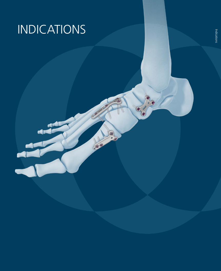
INDICATIONS
The Synthes 2.4 mm/2.7 mm Variable Angle LCP Forefoot/Midfoot System is indicated for fixation of osteotomies, fusions, fractures, nonunions, malunions, and replantations of small bones and small bone fragments in adult and adolescent (12–21 years) patients, including the foot and ankle, and particularly in osteopenic bone.
SYSTEM FEATURES
System Features
2.4 mm/2.7 mm Variable Angle LCP® Forefoot/Midfoot System Surgical Technique DePuy Synthes 5
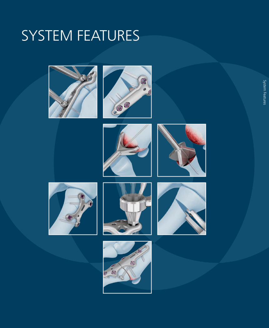
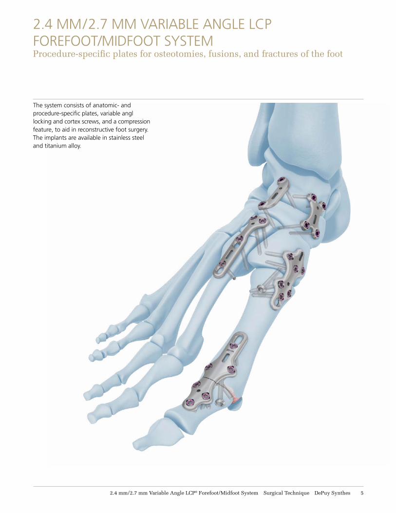
2.4 MM/2.7 MM VARIABLE ANGLE LCP FOREFOOT/MIDFOOT SYSTEM Procedure-specific plates for osteotomies, fusions, and fractures of the foot
The system consists of anatomic- and procedure-specific plates, variable angl locking and cortex screws, and a compression feature, to aid in reconstructive foot surgery. The implants are available in stainless steel and titanium alloy.
6 DePuy Synthes 2.4 mm/2.7 mm Variable Angle LCP® Forefoot/Midfoot System Surgical Technique
COMPRESSION SYSTEM
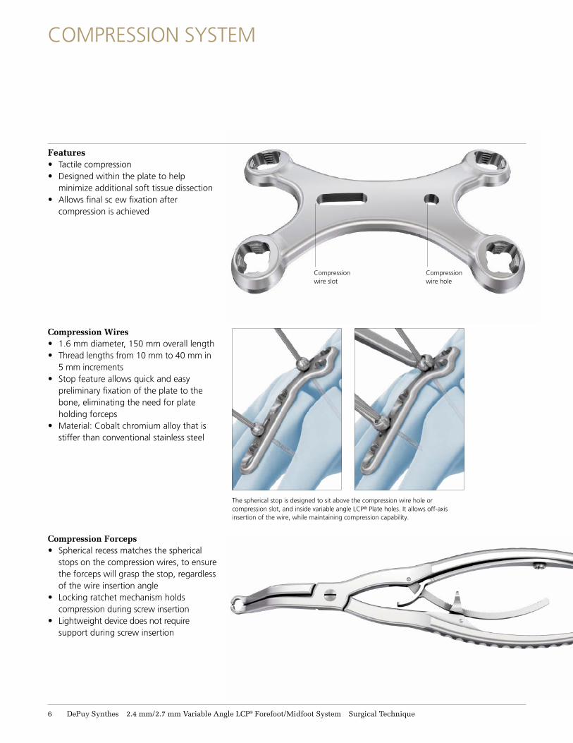
Features• Tactile compression • Designed within the plate to help
minimize additional soft tissue dissection • Allows final sc ew fixation after
compression is achieved
Compression wire slot
Compression wire hole
Compression Wires • 1.6 mm diameter, 150 mm overall length • Thread lengths from 10 mm to 40 mm in
5 mm increments • Stop feature allows quick and easy
preliminary fixation of the plate to thebone, eliminating the need for plate holding forceps
• Material: Cobalt chromium alloy that is stiffer than conventional stainless steel
Compression Forceps • Spherical recess matches the spherical
stops on the compression wires, to ensure the forceps will grasp the stop, regardless of the wire insertion angle
• Locking ratchet mechanism holds compression during screw insertion
• Lightweight device does not require support during screw insertion
The spherical stop is designed to sit above the compression wire hole or compression slot, and inside variable angle LCP® Plate holes. It allows off-axis insertion of the wire, while maintaining compression capability.
2.4 mm/2.7 mm Variable Angle LCP® Forefoot/Midfoot System Surgical Technique DePuy Synthes 7
2.4 MM/2.7 MM VARIABLE ANGLE LCP TECHNOLOGY
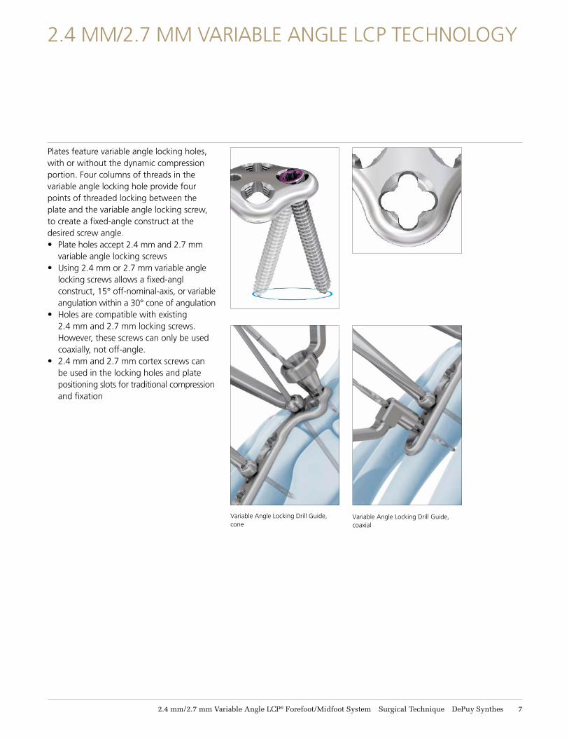
Plates feature variable angle locking holes, with or without the dynamic compression portion. Four columns of threads in the variable angle locking hole provide four points of threaded locking between the plate and the variable angle locking screw, to create a fixed-angle construct at the desired screw angle.• Plate holes accept 2.4 mm and 2.7 mm
variable angle locking screws • Using 2.4 mm or 2.7 mm variable angle
locking screws allows a fixed-angl construct, 15° off-nominal-axis, or variable angulation within a 30° cone of angulation
• Holes are compatible with existing 2.4 mm and 2.7 mm locking screws. However, these screws can only be used coaxially, not off-angle.
• 2.4 mm and 2.7 mm cortex screws can be used in the locking holes and plate positioning slots for traditional compression and fixation
Variable Angle Locking Drill Guide, cone
Variable Angle Locking Drill Guide, coaxial
8 DePuy Synthes 2.4 mm/2.7 mm Variable Angle LCP® Forefoot/Midfoot System Surgical Technique
PROXIMAL AND DISTAL REAMERS
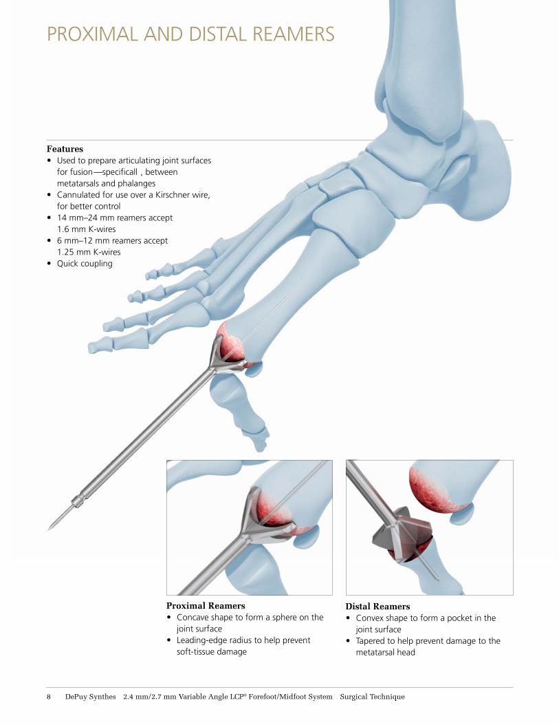
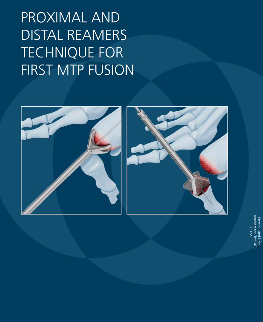
Proximal Reamers • Concave shape to form a sphere on the
joint surface • Leading-edge radius to help prevent
soft-tissue damage
Distal Reamers • Convex shape to form a pocket in the
joint surface • Tapered to help prevent damage to the
metatarsal head
Features• Used to prepare articulating joint surfaces
for fusion—specificall , between metatarsals and phalanges
• Cannulated for use over a Kirschner wire, for better control
• 14 mm–24 mm reamers accept 1.6 mm K-wires
• 6 mm–12 mm reamers accept 1.25 mm K-wires
• Quick coupling
2.4 mm/2.7 mm Variable Angle LCP® Forefoot/Midfoot System Surgical Technique DePuy Synthes 9
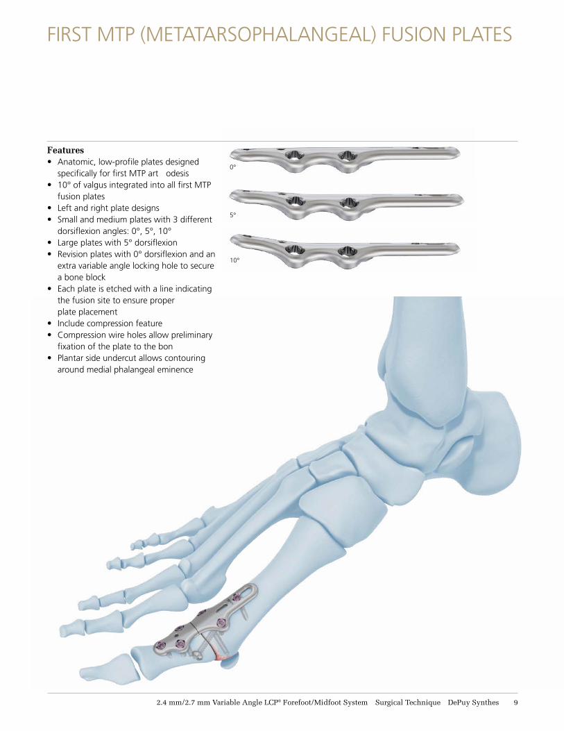
FIRST MTP (METATARSOPHALANGEAL) FUSION PLATES
0°
5°
10°
Features• Anatomic, low-profile plates designed
specifically for first MTP art odesis • 10° of valgus integrated into all first MTP
fusion plates • Left and right plate designs • Small and medium plates with 3 different
dorsiflexion angles: 0°, 5°, 10°• Large plates with 5° dorsiflexion• Revision plates with 0° dorsiflexion and an
extra variable angle locking hole to secure a bone block
• Each plate is etched with a line indicating the fusion site to ensure proper plate placement
• Include compression feature• Compression wire holes allow preliminary
fixation of the plate to the bon• Plantar side undercut allows contouring
around medial phalangeal eminence

11 DePuy Synthes 2.4 mm/2.7 mm Variable Angle LCP® Forefoot/Midfoot System Surgical Technique
Opening Wedge Measuring Instrument • Thin tip slides into osteotomy site and
opens the wedge for the desired correction • Ratchet mechanism holds osteotomy open • Measurement scale indicates the appropriate
size wedge for the desired opening
OPENING WEDGE OSTEOTOMY PLATES
Features• Anatomic, low-profile plates designe
specifically for metatarsal opening wedgeosteotomy for hallux valgus correction
• 6 plates with varying spacer lengths: 0 mm, 3 mm, 4 mm, 5 mm, 6 mm, and 7 mm
• Spacer includes a tapered tip for easier insertion into the osteotomy site
• Compression wire holes allow for preliminary fixation of the plate to the bone
2.4 mm/2.7 mm Variable Angle LCP® Forefoot/Midfoot System Surgical Technique DePuy Synthes 11
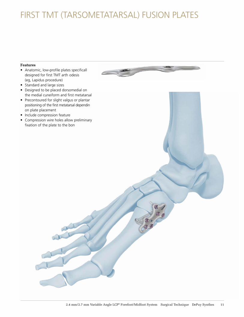
FIRST TMT (TARSOMETATARSAL) FUSION PLATES
Features• Anatomic, low-profile plates specificall
designed for first TMT arth odesis (eg, Lapidus procedure)
• Standard and large sizes • Designed to be placed dorsomedial on
the medial cuneiform and first metatarsal• Precontoured for slight valgus or plantar
positioning of the first metatarsal dependin on plate placement
• Include compression feature • Compression wire holes allow preliminary
fixation of the plate to the bon
12 DePuy Synthes 2.4 mm/2.7 mm Variable Angle LCP® Forefoot/Midfoot System Surgical Technique
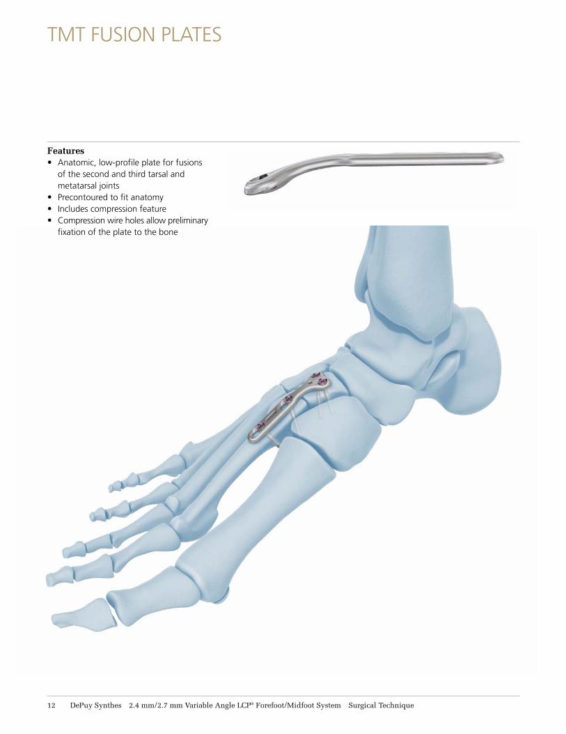
TMT FUSION PLATES
Features• Anatomic, low-profile plate for fusions
of the second and third tarsal and metatarsal joints
• Precontoured to fit anatomy• Includes compression feature • Compression wire holes allow preliminary
fixation of the plate to the bone
2.4 mm/2.7 mm Variable Angle LCP® Forefoot/Midfoot System Surgical Technique DePuy Synthes 13
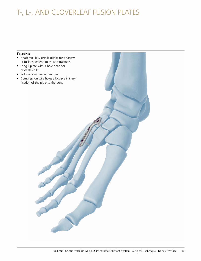
T-, L-, AND CLOVERLEAF FUSION PLATES
Features• Anatomic, low-profile plates for a variety
of fusions, osteotomies, and fractures• Long T-plate with 3-hole head for
more flexibilit• Include compression feature • Compression wire holes allow preliminary
fixation of the plate to the bone
14 DePuy Synthes 2.4 mm/2.7 mm Variable Angle LCP® Forefoot/Midfoot System Surgical Technique
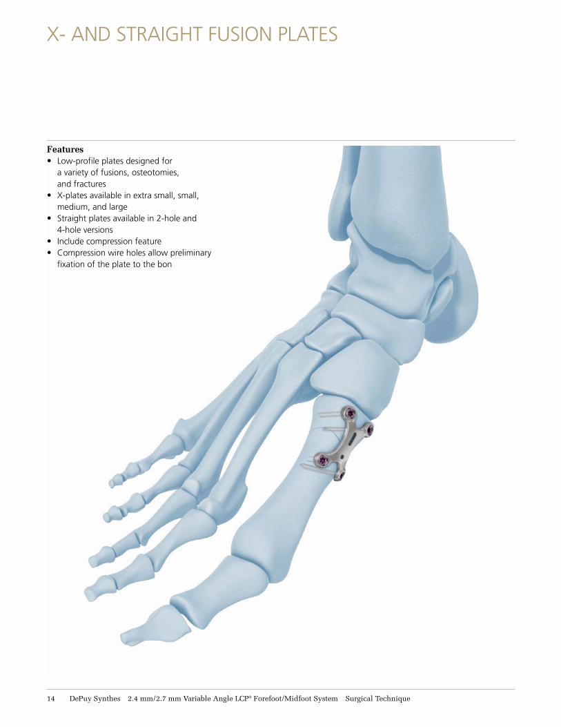
X- AND STRAIGHT FUSION PLATES
Features• Low-profile plates designed for
a variety of fusions, osteotomies, and fractures
• X-plates available in extra small, small, medium, and large
• Straight plates available in 2-hole and 4-hole versions
• Include compression feature • Compression wire holes allow preliminary
fixation of the plate to the bon
2.4 mm/2.7 mm Variable Angle LCP® Forefoot/Midfoot System Surgical Technique DePuy Synthes 15
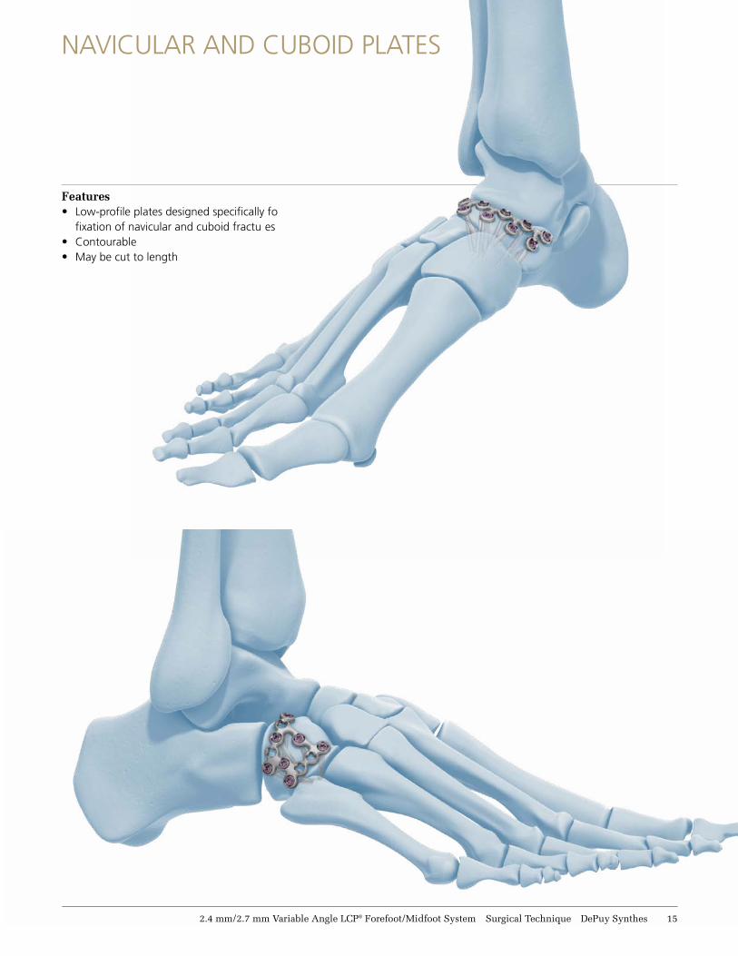
Features• Low-profile plates designed specifically fo
fixation of navicular and cuboid fractu es • Contourable • May be cut to length
NAVICULAR AND CUBOID PLATES
16 DePuy Synthes 2.4 mm/2.7 mm Variable Angle LCP® Forefoot/Midfoot System Surgical Technique
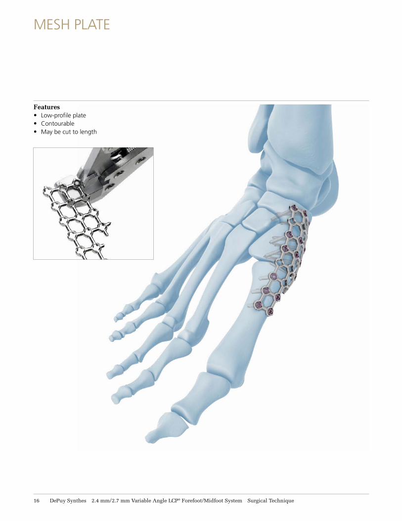
MESH PLATE
Features• Low-profile plate• Contourable • May be cut to length
2.4 mm/2.7 mm Variable Angle LCP® Forefoot/Midfoot System Surgical Technique DePuy Synthes 17
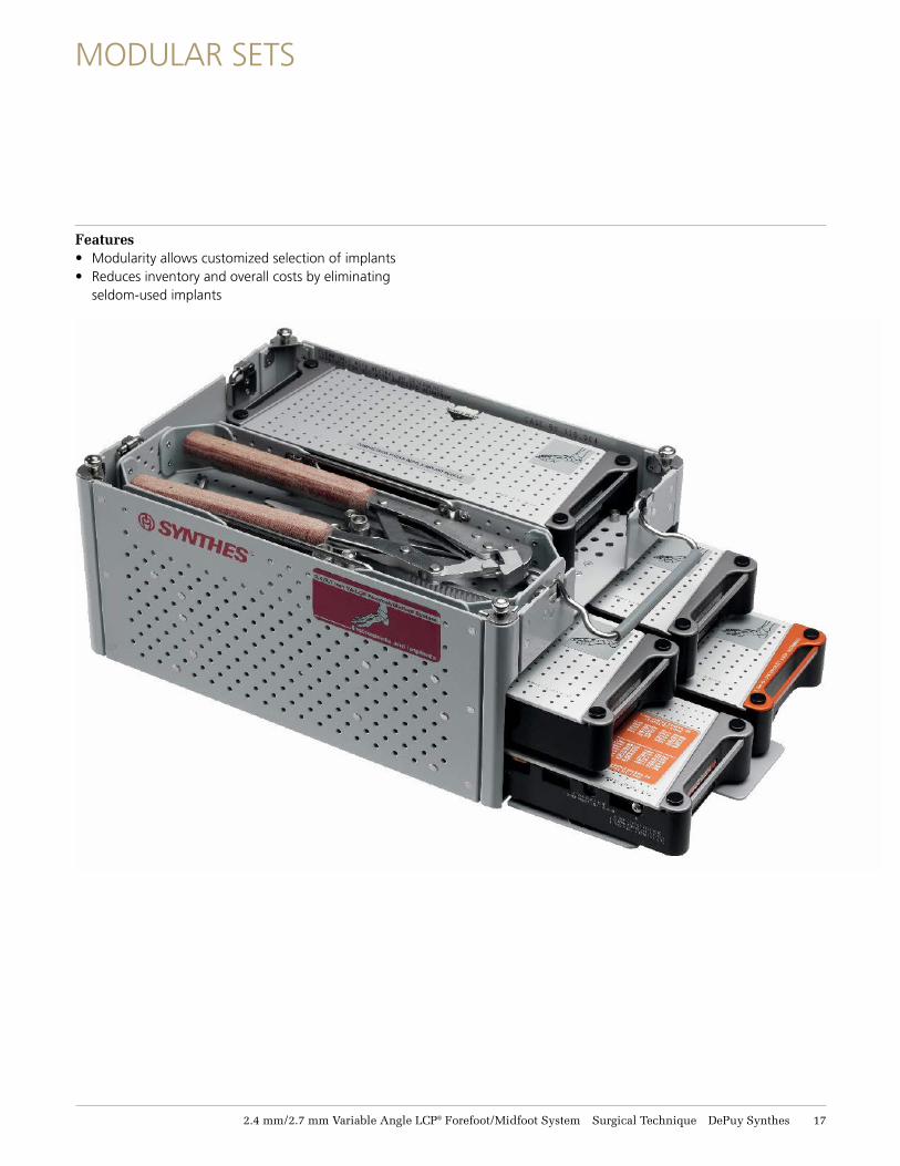
MODULAR SETS
Features• Modularity allows customized selection of implants • Reduces inventory and overall costs by eliminating
seldom-used implants
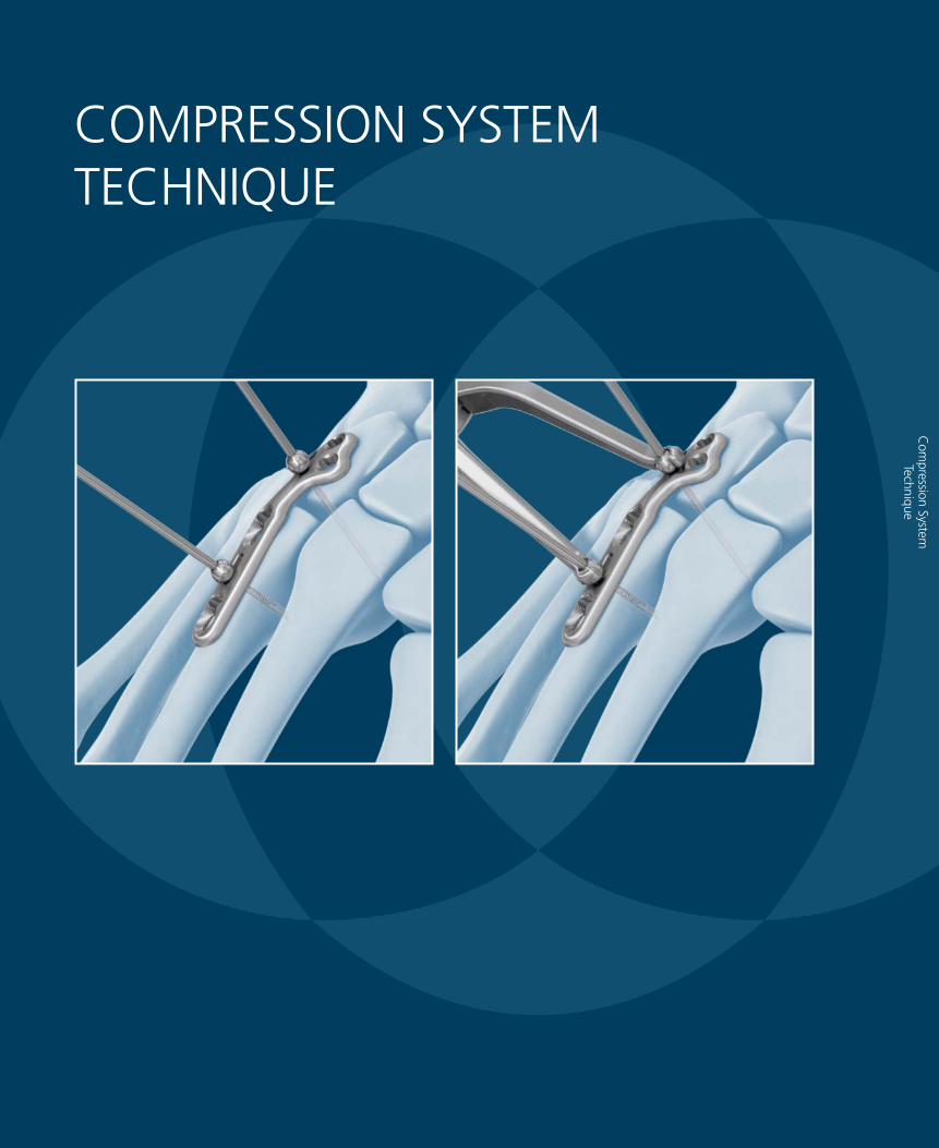
COMPRESSION SYSTEM TECHNIQUE
Com
pression System
Technique
2.4 mm/2.7 mm Variable Angle LCP® Forefoot/Midfoot System Surgical Technique DePuy Synthes 19
COMPRESSION SYSTEM TECHNIQUE
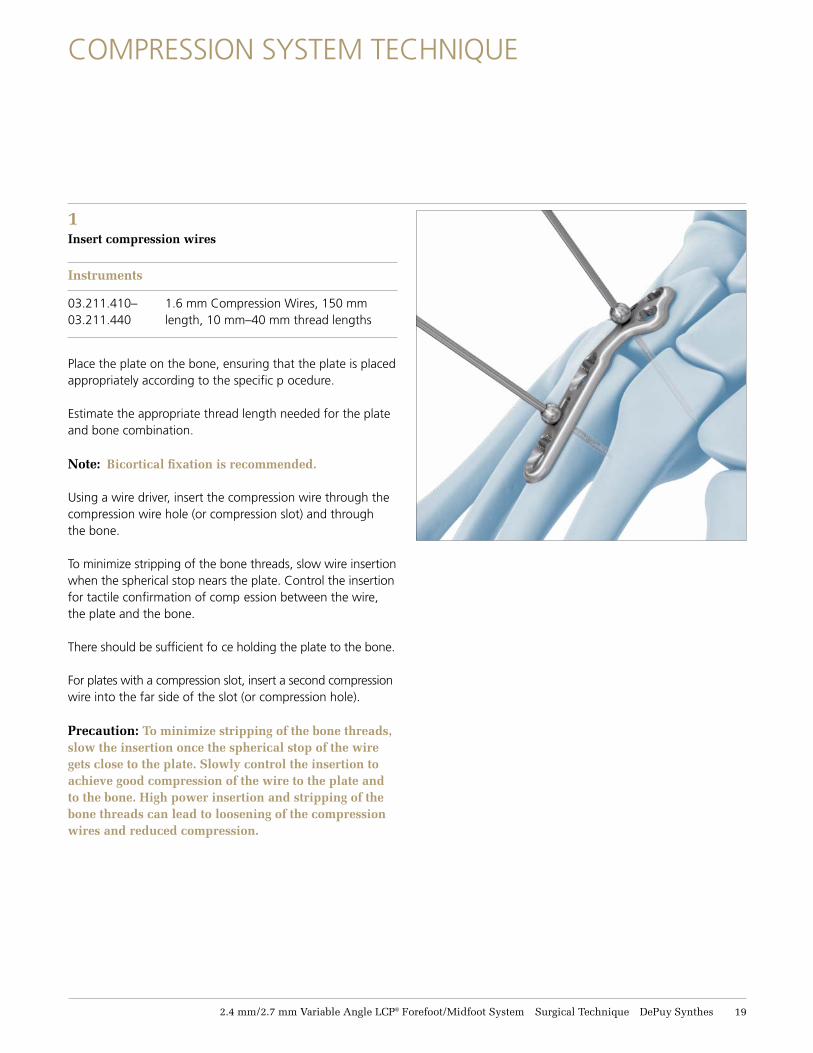
1Insert compression wires
Instruments
03.211.410– 1.6 mm Compression Wires, 150 mm 03.211.440 length, 10 mm–40 mm thread lengths
Place the plate on the bone, ensuring that the plate is placed appropriately according to the specific p ocedure.
Estimate the appropriate thread length needed for the plate and bone combination.
Note: Bicortical fixation is recommended.
Using a wire driver, insert the compression wire through the compression wire hole (or compression slot) and through the bone.
To minimize stripping of the bone threads, slow wire insertion when the spherical stop nears the plate. Control the insertion for tactile confirmation of comp ession between the wire, the plate and the bone.
There should be sufficient fo ce holding the plate to the bone.
For plates with a compression slot, insert a second compression wire into the far side of the slot (or compression hole).
Precaution: To minimize stripping of the bone threads, slow the insertion once the spherical stop of the wire gets close to the plate. Slowly control the insertion to achieve good compression of the wire to the plate and to the bone. High power insertion and stripping of the bone threads can lead to loosening of the compression wires and reduced compression.
21 DePuy Synthes 2.4 mm/2.7 mm Variable Angle LCP® Forefoot/Midfoot System Surgical Technique
Compression System Technique
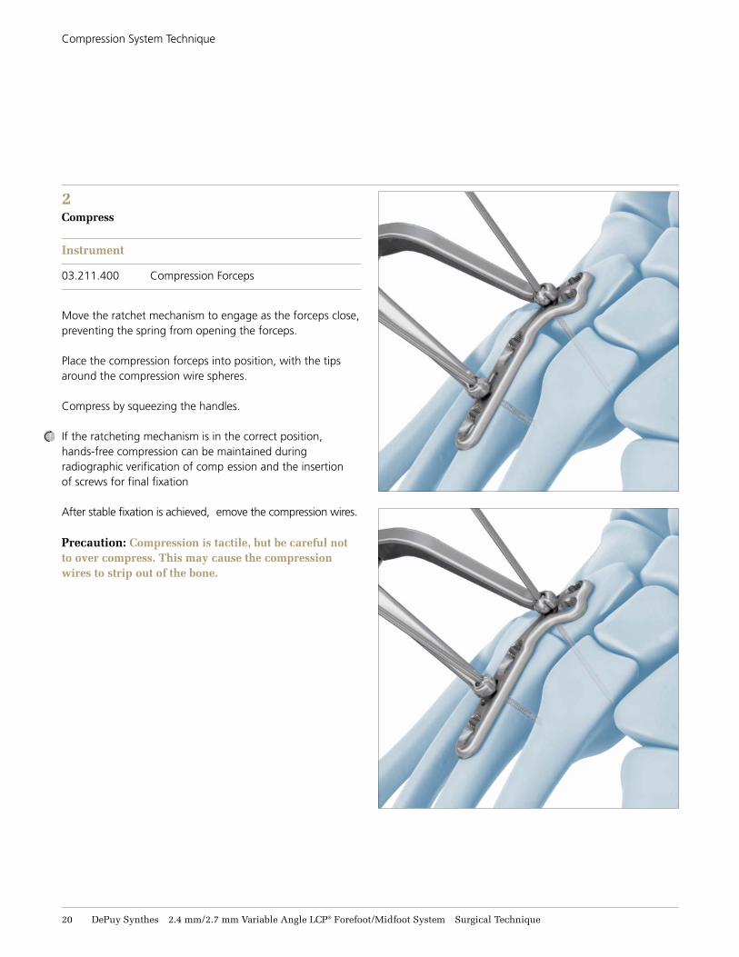
2 Compress
Instrument
03.211.400 Compression Forceps
Move the ratchet mechanism to engage as the forceps close, preventing the spring from opening the forceps.
Place the compression forceps into position, with the tips around the compression wire spheres.
Compress by squeezing the handles.
If the ratcheting mechanism is in the correct position, hands-free compression can be maintained during radiographic verification of comp ession and the insertion of screws for final fixation
After stable fixation is achieved, emove the compression wires.
Precaution: Compression is tactile, but be careful not to over compress. This may cause the compression wires to strip out of the bone.
2.4 mm/2.7 mm Variable Angle LCP® Forefoot/Midfoot System Surgical Technique DePuy Synthes 21
INSTRUMENTS
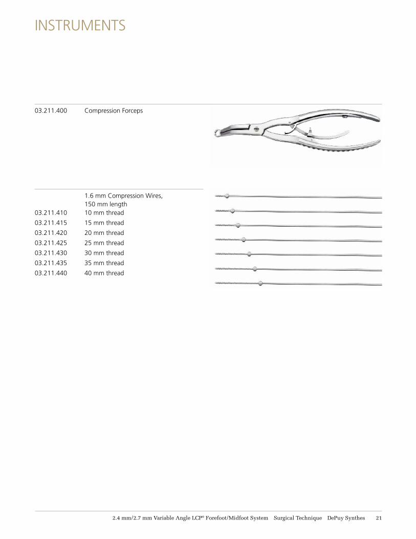
03.211.400 Compression Forceps
1.6 mm Compression Wires, 150 mm length
03.211.410 10 mm thread
03.211.415 15 mm thread
03.211.420 20 mm thread
03.211.425 25 mm thread
03.211.430 30 mm thread
03.211.435 35 mm thread
03.211.440 40 mm thread
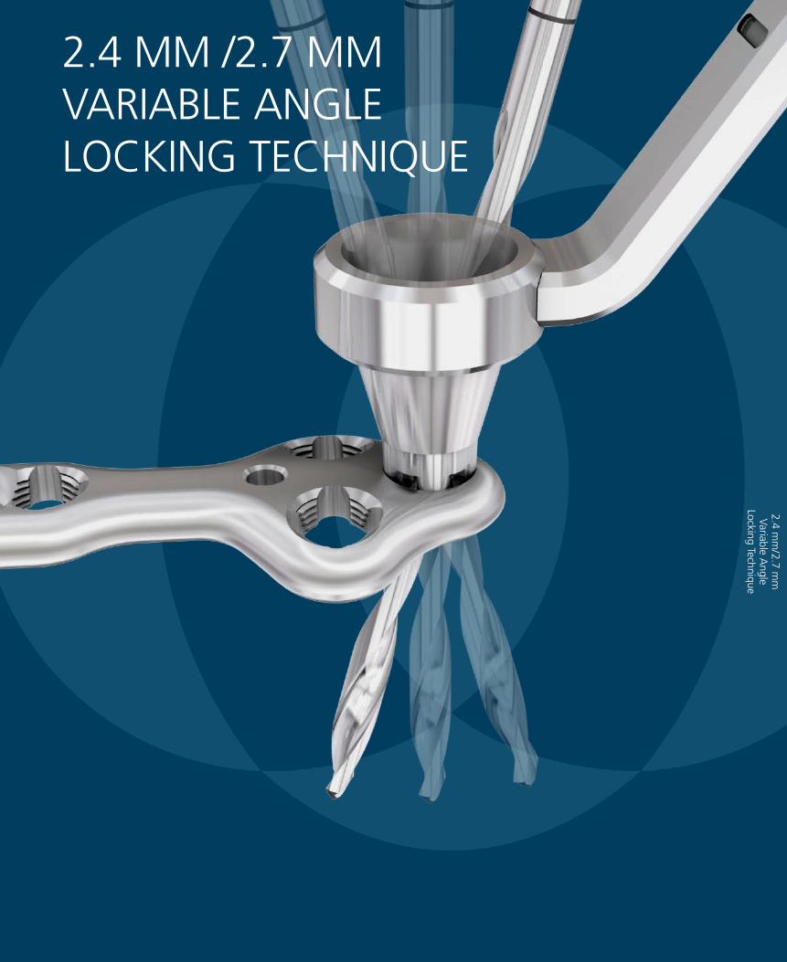
2.4 MM /2.7 MM VARIABLE ANGLE LOCKING TECHNIQUE
2.4 mm
/2.7 mm
Variable A
ngle Locking Technique
2.4 mm/2.7 mm Variable Angle LCP® Forefoot/Midfoot System Surgical Technique DePuy Synthes 23
2.4 MM/2.7 MM VARIABLE ANGLE LOCKING TECHNIQUE
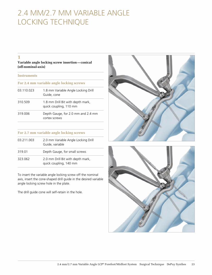
1Variable angle locking screw insertion—conical (off-nominal-axis)
Instruments
For 2.4 mm variable angle locking screws
03.110.023 1.8 mm Variable Angle Locking Drill Guide, cone
310.509 1.8 mm Drill Bit with depth mark, quick coupling, 110 mm
319.006 Depth Gauge, for 2.0 mm and 2.4 mm cortex screws
For 2.7 mm variable angle locking screws
03.211.003 2.0 mm Variable Angle Locking Drill Guide, variable
319.01 Depth Gauge, for small screws
323.062 2.0 mm Drill Bit with depth mark, quick coupling, 140 mm
To insert the variable angle locking screw off the nominal axis, insert the cone-shaped drill guide in the desired variable angle locking screw hole in the plate.
The drill guide cone will self-retain in the hole.
24 DePuy Synthes 2.4 mm/2.7 mm Variable Angle LCP® Forefoot/Midfoot System Surgical Technique
2.4 mm/2.7 mm Variable Angle Locking Technique
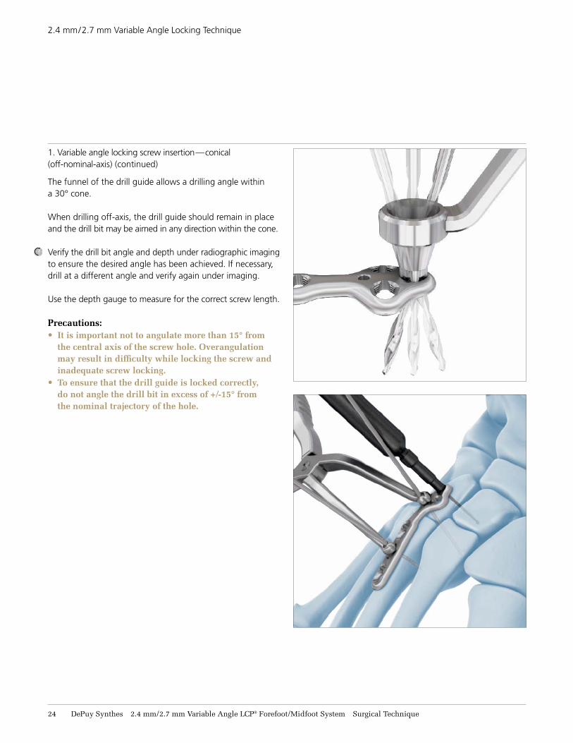
1. Variable angle locking screw insertion—conical (off-nominal-axis) (continued) The funnel of the drill guide allows a drilling angle within a 30° cone.
When drilling off-axis, the drill guide should remain in place and the drill bit may be aimed in any direction within the cone.
Verify the drill bit angle and depth under radiographic imaging to ensure the desired angle has been achieved. If necessary, drill at a different angle and verify again under imaging.
Use the depth gauge to measure for the correct screw length.
Precautions:• It is important not to angulate more than 15° from
the central axis of the screw hole. Overangulation may result in difficulty while locking the screw and inadequate screw locking.
• To ensure that the drill guide is locked correctly, do not angle the drill bit in excess of +/-15° from the nominal trajectory of the hole.
2.4 mm/2.7 mm Variable Angle LCP® Forefoot/Midfoot System Surgical Technique DePuy Synthes 25
2.4 mm/2.7 mm Variable Angle Locking Technique
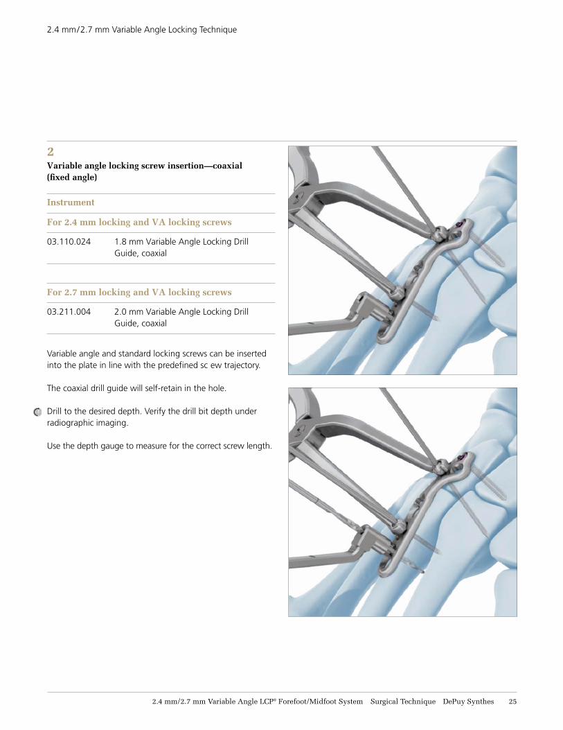
2Variable angle locking screw insertion—coaxial (fixed angle)
Instrument
For 2.4 mm locking and VA locking screws
03.110.024 1.8 mm Variable Angle Locking Drill Guide, coaxial
For 2.7 mm locking and VA locking screws
03.211.004 2.0 mm Variable Angle Locking Drill Guide, coaxial
Variable angle and standard locking screws can be inserted into the plate in line with the predefined sc ew trajectory.
The coaxial drill guide will self-retain in the hole.
Drill to the desired depth. Verify the drill bit depth under radiographic imaging. Use the depth gauge to measure for the correct screw length.
26 DePuy Synthes 2.4 mm/2.7 mm Variable Angle LCP® Forefoot/Midfoot System Surgical Technique
2.4 mm/2.7 mm Variable Angle Locking Technique
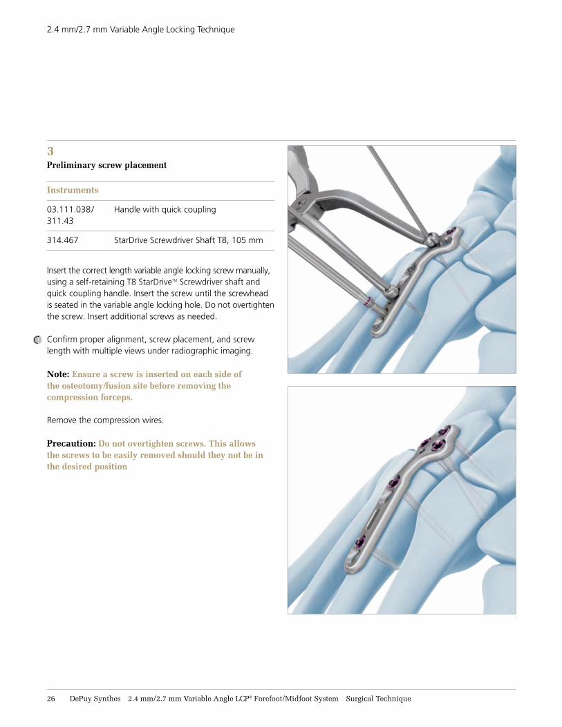
3Preliminary screw placement
Instruments
03.111.038/ Handle with quick coupling 311.43
314.467 StarDrive Screwdriver Shaft T8, 105 mm
Insert the correct length variable angle locking screw manually, using a self-retaining T8 StarDriveTM Screwdriver shaft and quick coupling handle. Insert the screw until the screwhead is seated in the variable angle locking hole. Do not overtighten the screw. Insert additional screws as needed.
Confirm proper alignment, screw placement, and screwlength with multiple views under radiographic imaging.
Note: Ensure a screw is inserted on each side of the osteotomy/fusion site before removing the compression forceps.
Remove the compression wires.
Precaution: Do not overtighten screws. This allows the screws to be easily removed should they not be in the desired position
2.4 mm/2.7 mm Variable Angle LCP® Forefoot/Midfoot System Surgical Technique DePuy Synthes 27
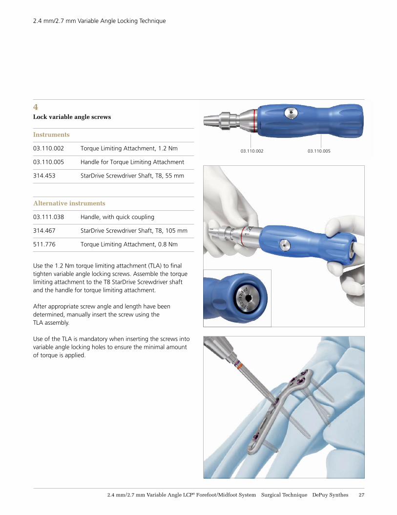
4Lock variable angle screws
Instruments
03.110.002 Torque Limiting Attachment, 1.2 Nm
03.110.005 Handle for Torque Limiting Attachment
314.453 StarDrive Screwdriver Shaft, T8, 55 mm
Alternative instruments
03.111.038 Handle, with quick coupling
314.467 StarDrive Screwdriver Shaft, T8, 105 mm
511.776 Torque Limiting Attachment, 0.8 Nm
Use the 1.2 Nm torque limiting attachment (TLA) to finaltighten variable angle locking screws. Assemble the torque limiting attachment to the T8 StarDrive Screwdriver shaft and the handle for torque limiting attachment.
After appropriate screw angle and length have been determined, manually insert the screw using the TLA assembly.
Use of the TLA is mandatory when inserting the screws into variable angle locking holes to ensure the minimal amount of torque is applied.
03.110.002 03.110.005
2.4 mm/2.7 mm Variable Angle Locking Technique
28 DePuy Synthes 2.4 mm/2.7 mm Variable Angle LCP® Forefoot/Midfoot System Surgical Technique
2.4 mm/2.7 mm Variable Angle LCP Technology
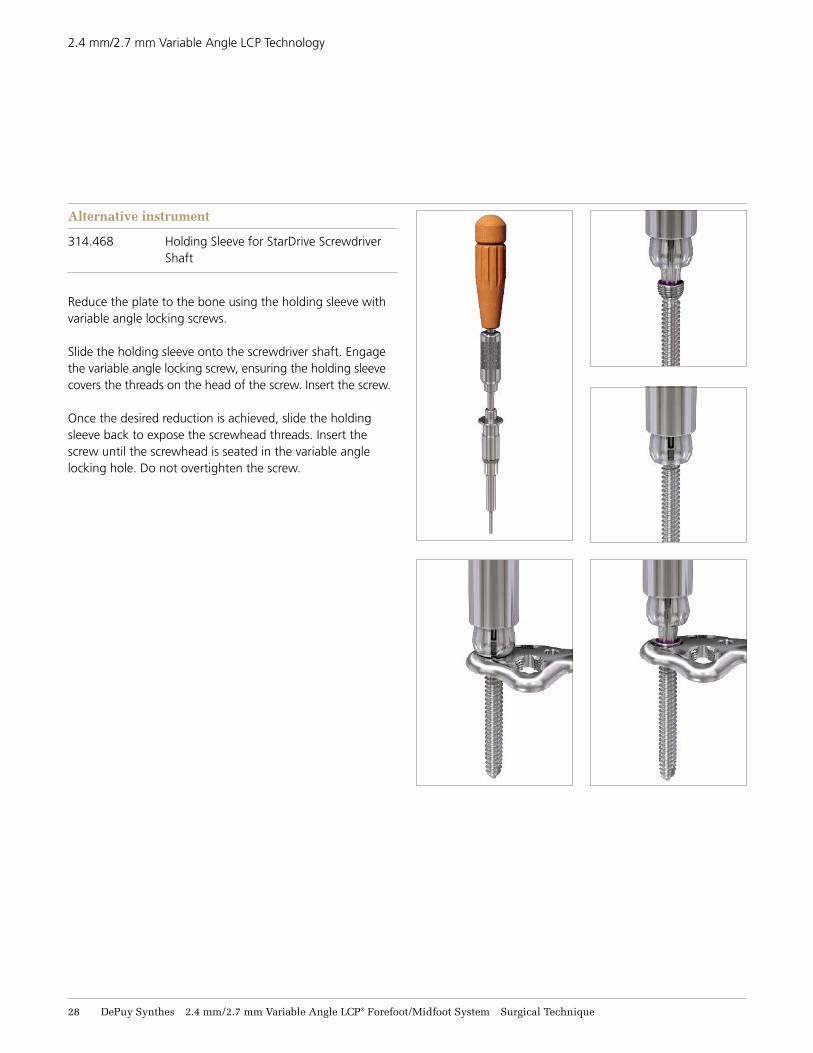
Alternative instrument
314.468 Holding Sleeve for StarDrive Screwdriver Shaft
Reduce the plate to the bone using the holding sleeve with variable angle locking screws.
Slide the holding sleeve onto the screwdriver shaft. Engage the variable angle locking screw, ensuring the holding sleeve covers the threads on the head of the screw. Insert the screw.
Once the desired reduction is achieved, slide the holding sleeve back to expose the screwhead threads. Insert the screw until the screwhead is seated in the variable angle locking hole. Do not overtighten the screw.
2.4 mm/2.7 mm Variable Angle LCP® Forefoot/Midfoot System Surgical Technique DePuy Synthes 29
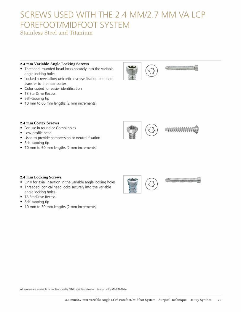
SCREWS USED WITH THE 2.4 MM/2.7 MM VA LCP FOREFOOT/MIDFOOT SYSTEMStainless Steel and Titanium
2.4 mm Variable Angle Locking Screws• Threaded, rounded head locks securely into the variable
angle locking holes • Locked screws allow unicortical screw fixation and load
transfer to the near cortex • Color coded for easier identification• T8 StarDrive Recess• Self-tapping tip• 10 mm to 60 mm lengths (2 mm increments)
2.4 mm Cortex Screws• For use in round or Combi holes • Low-profile head• Used to provide compression or neutral fixation• Self-tapping tip • 10 mm to 60 mm lengths (2 mm increments)
2.4 mm Locking Screws• Only for axial insertion in the variable angle locking holes • Threaded, conical head locks securely into the variable
angle locking holes • T8 StarDrive Recess• Self-tapping tip • 10 mm to 30 mm lengths (2 mm increments)
All screws are available in implant-quality 316L stainless steel or titanium alloy (Ti-6AI-7Nb)
31 DePuy Synthes 2.4 mm/2.7 mm Variable Angle LCP® Forefoot/Midfoot System Surgical Technique
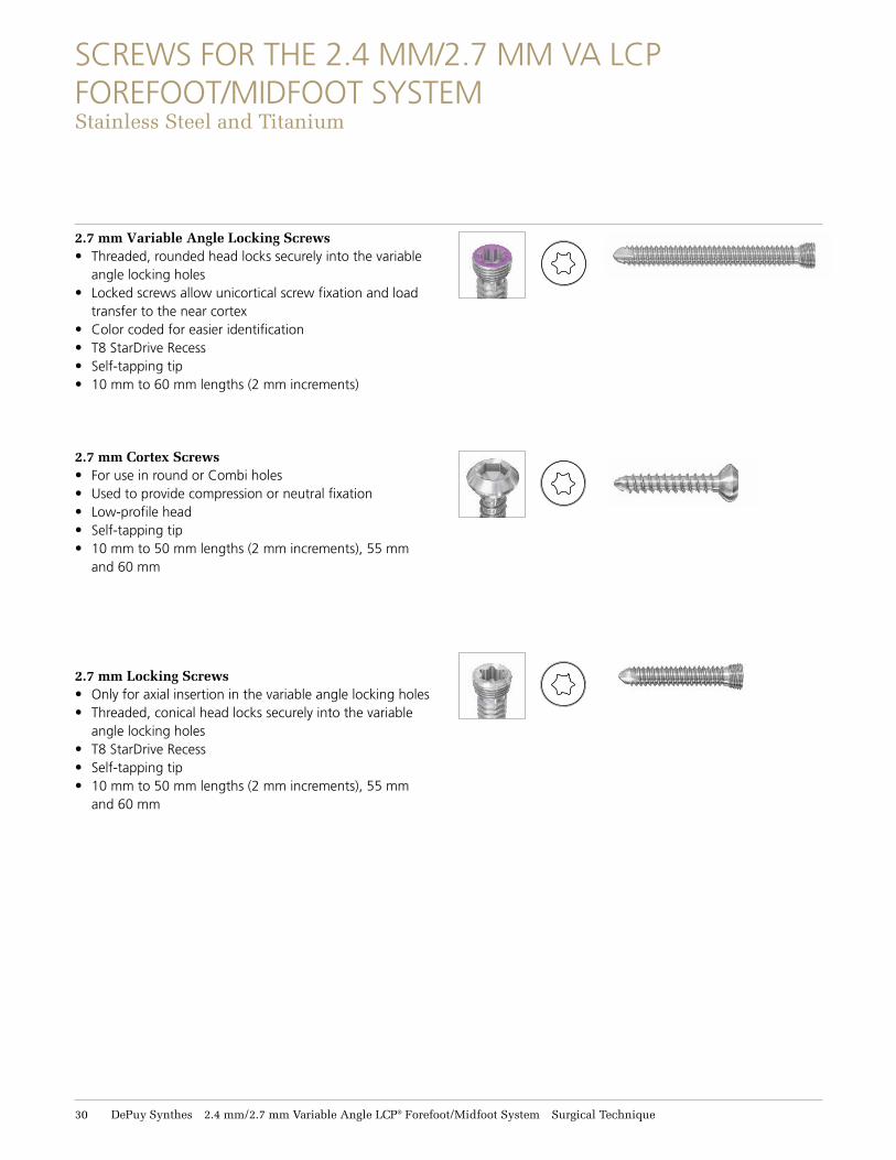
SCREWS FOR THE 2.4 MM/2.7 MM VA LCP FOREFOOT/MIDFOOT SYSTEM Stainless Steel and Titanium
2.7 mm Variable Angle Locking Screws• Threaded, rounded head locks securely into the variable
angle locking holes • Locked screws allow unicortical screw fixation and load
transfer to the near cortex • Color coded for easier identification• T8 StarDrive Recess• Self-tapping tip • 10 mm to 60 mm lengths (2 mm increments)
2.7 mm Cortex Screws• For use in round or Combi holes • Used to provide compression or neutral fixation• Low-profile head• Self-tapping tip • 10 mm to 50 mm lengths (2 mm increments), 55 mm
and 60 mm
2.7 mm Locking Screws• Only for axial insertion in the variable angle locking holes • Threaded, conical head locks securely into the variable
angle locking holes • T8 StarDrive Recess• Self-tapping tip • 10 mm to 50 mm lengths (2 mm increments), 55 mm
and 60 mm
2.4 mm/2.7 mm Variable Angle LCP® Forefoot/Midfoot System Surgical Technique DePuy Synthes 31
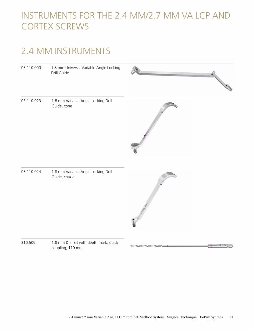
INSTRUMENTS FOR THE 2.4 MM/2.7 MM VA LCP AND CORTEX SCREWS
2.4 MM INSTRUMENTS
03.110.000 1.8 mm Universal Variable Angle Locking Drill Guide
03.110.023 1.8 mm Variable Angle Locking Drill Guide, cone
03.110.024 1.8 mm Variable Angle Locking Drill Guide, coaxial
310.509 1.8 mm Drill Bit with depth mark, quick coupling, 110 mm
32 DePuy Synthes 2.4 mm/2.7 mm Variable Angle LCP® Forefoot/Midfoot System Surgical Technique
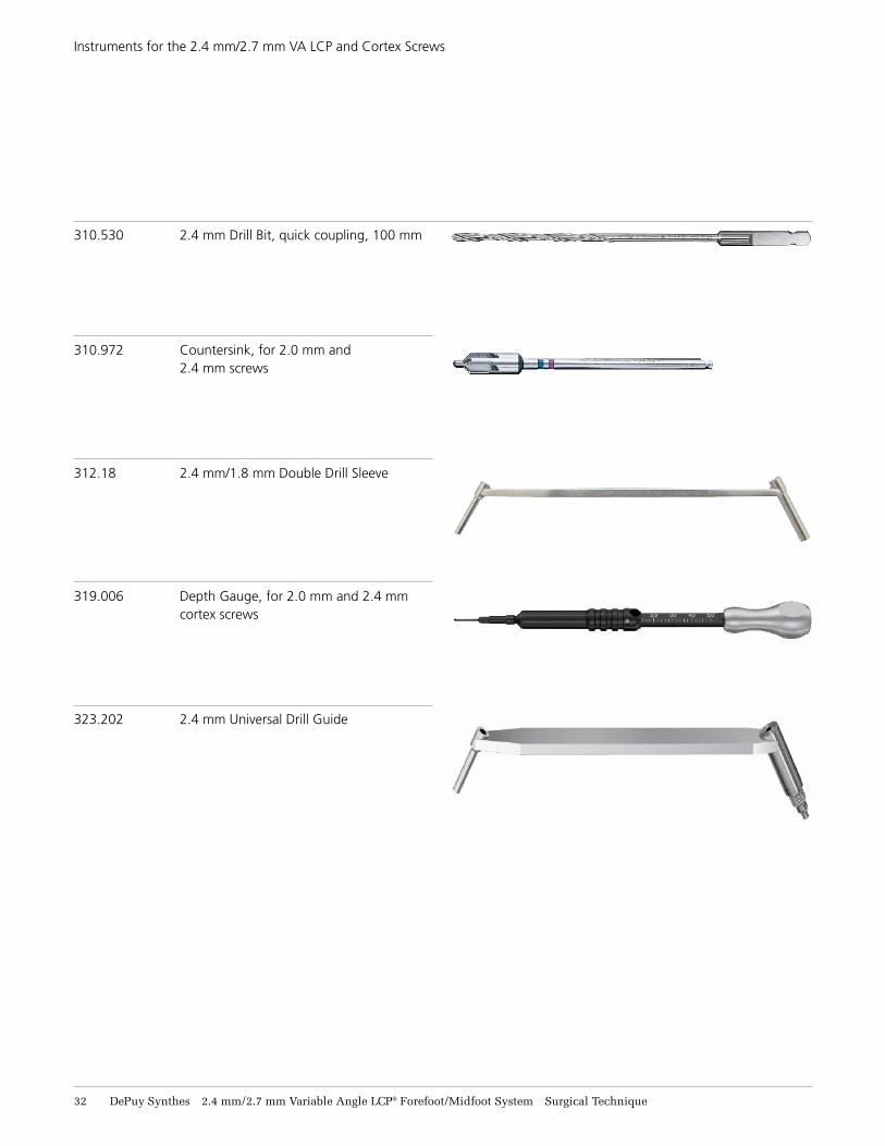
310.530 2.4 mm Drill Bit, quick coupling, 100 mm
310.972 Countersink, for 2.0 mm and 2.4 mm screws
312.18 2.4 mm/1.8 mm Double Drill Sleeve
319.006 Depth Gauge, for 2.0 mm and 2.4 mm cortex screws
323.202 2.4 mm Universal Drill Guide
Instruments for the 2.4 mm/2.7 mm VA LCP and Cortex Screws
2.4 mm/2.7 mm Variable Angle LCP® Forefoot/Midfoot System Surgical Technique DePuy Synthes 33
Instruments for the 2.4 mm/2.7 mm VA LCP and Cortex Screws
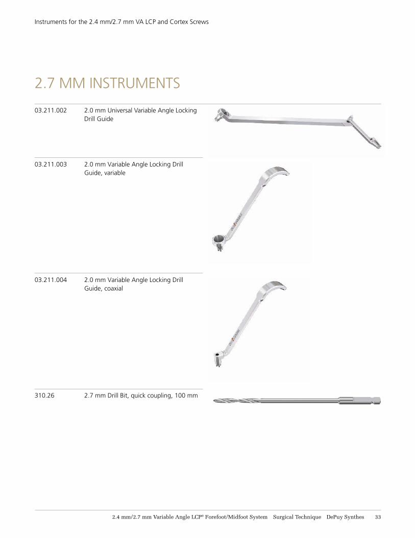
03.211.002 2.0 mm Universal Variable Angle Locking Drill Guide
03.211.003 2.0 mm Variable Angle Locking Drill Guide, variable
03.211.004 2.0 mm Variable Angle Locking Drill Guide, coaxial
310.26 2.7 mm Drill Bit, quick coupling, 100 mm
2.7 MM INSTRUMENTS
34 DePuy Synthes 2.4 mm/2.7 mm Variable Angle LCP® Forefoot/Midfoot System Surgical Technique
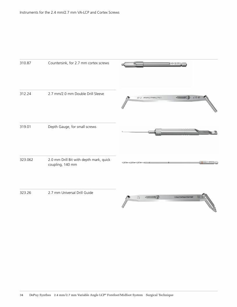
310.87 Countersink, for 2.7 mm cortex screws
312.24 2.7 mm/2.0 mm Double Drill Sleeve
319.01 Depth Gauge, for small screws
323.062 2.0 mm Drill Bit with depth mark, quick coupling, 140 mm
323.26 2.7 mm Universal Drill Guide
Instruments for the 2.4 mm/2.7 mm VA-LCP and Cortex Screws
2.4 mm/2.7 mm Variable Angle LCP® Forefoot/Midfoot System Surgical Technique DePuy Synthes 35
Instruments for the 2.4 mm/2.7 mm VA-LCP and Cortex Screws
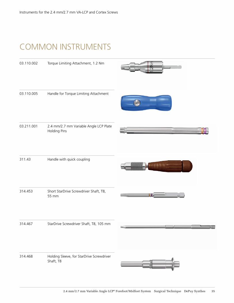
03.110.002 Torque Limiting Attachment, 1.2 Nm
03.110.005 Handle for Torque Limiting Attachment
311.43 Handle with quick coupling
03.211.001 2.4 mm/2.7 mm Variable Angle LCP Plate Holding Pins
314.453 Short StarDrive Screwdriver Shaft, T8, 55 mm
314.467 StarDrive Screwdriver Shaft, T8, 105 mm
314.468 Holding Sleeve, for StarDrive Screwdriver Shaft, T8
COMMON INSTRUMENTS
PROXIMAL AND DISTAL REAMERS TECHNIQUE FOR FIRST MTP FUSION
Proximal and D
istal Ream
ers for First MTP
Fusion
2.4 mm/2.7 mm Variable Angle LCP® Forefoot/Midfoot System Surgical Technique DePuy Synthes 37
PROXIMAL AND DISTAL REAMERS TECHNIQUE FOR FIRST MTP FUSION
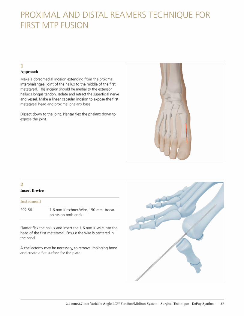
1 Approach
Make a dorsomedial incision extending from the proximal interphalangeal joint of the hallux to the middle of the first metatarsal. This incision should be medial to the extensor hallucis longus tendon. Isolate and retract the superficial nerve and vessel. Make a linear capsular incision to expose the firstmetatarsal head and proximal phalanx base.
Dissect down to the joint. Plantar flex the phalanx down toexpose the joint.
2Insert K-wire
Instrument
292.56 1.6 mm Kirschner Wire, 150 mm, trocar points on both ends
Plantar flex the hallux and insert the 1.6 mm K-wi e into the head of the first metatarsal. Ensu e the wire is centered in the canal.
A cheilectomy may be necessary, to remove impinging bone and create a flat surface for the plate.
38 DePuy Synthes 2.4 mm/2.7 mm Variable Angle LCP® Forefoot/Midfoot System Surgical Technique
Proximal and Distal Reamers Technique for First MTP Fusion
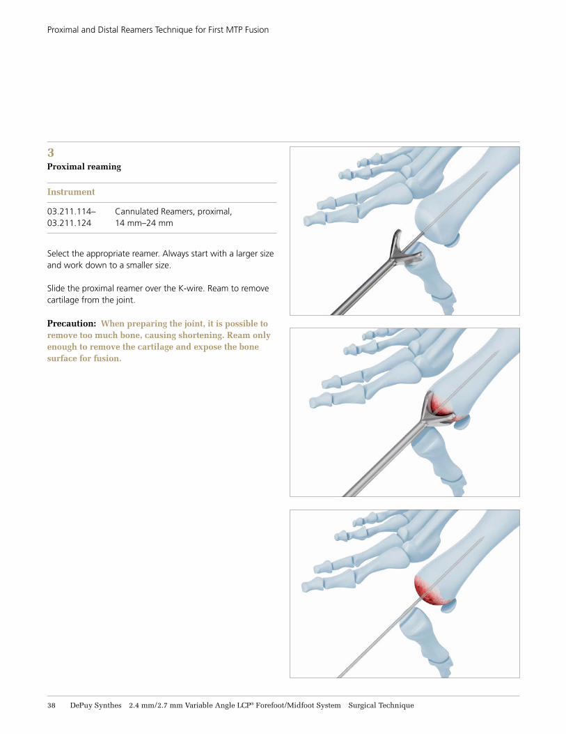
3 Proximal reaming
Instrument
03.211.114– Cannulated Reamers, proximal, 03.211.124 14 mm–24 mm
Select the appropriate reamer. Always start with a larger size and work down to a smaller size.
Slide the proximal reamer over the K-wire. Ream to remove cartilage from the joint.
Precaution: When preparing the joint, it is possible to remove too much bone, causing shortening. Ream only enough to remove the cartilage and expose the bone surface for fusion.
2.4 mm/2.7 mm Variable Angle LCP® Forefoot/Midfoot System Surgical Technique DePuy Synthes 39
Proximal and Distal Reamers Technique for First MTP Fusion
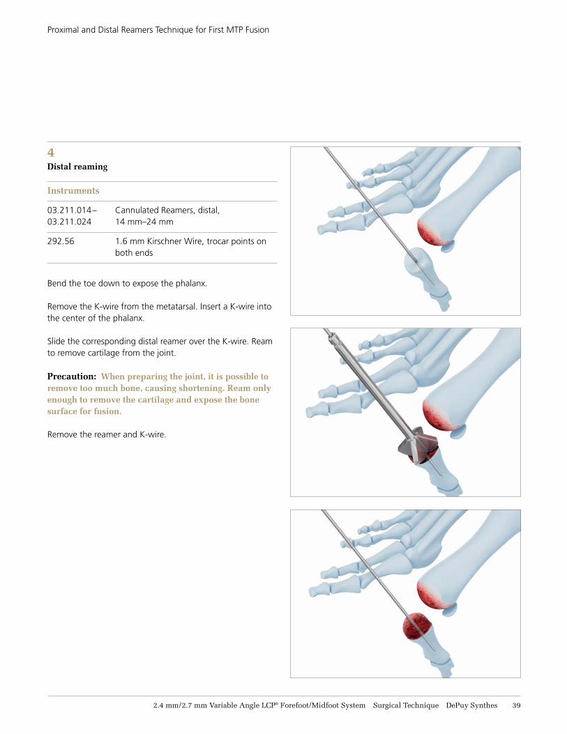
4 Distal reaming
Instruments
03.211.014– Cannulated Reamers, distal, 03.211.024 14 mm–24 mm
292.56 1.6 mm Kirschner Wire, trocar points on both ends
Bend the toe down to expose the phalanx.
Remove the K-wire from the metatarsal. Insert a K-wire into the center of the phalanx.
Slide the corresponding distal reamer over the K-wire. Ream to remove cartilage from the joint.
Precaution: When preparing the joint, it is possible to remove too much bone, causing shortening. Ream only enough to remove the cartilage and expose the bone surface for fusion.
Remove the reamer and K-wire.
41 DePuy Synthes 2.4 mm/2.7 mm Variable Angle LCP® Forefoot/Midfoot System Surgical Technique
INSTRUMENTS
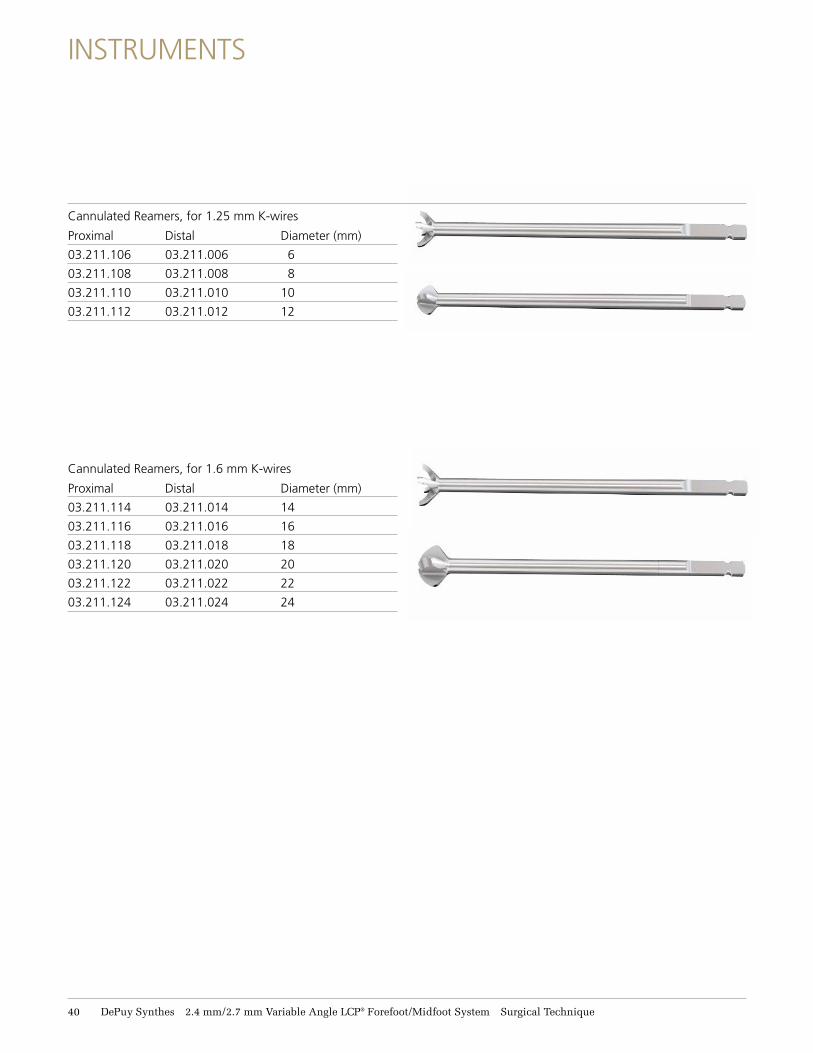
Cannulated Reamers, for 1.25 mm K-wires
Proximal Distal Diameter (mm)
03.211.106 03.211.006 6
03.211.108 03.211.008 8
03.211.110 03.211.010 10
03.211.112 03.211.012 12
Cannulated Reamers, for 1.6 mm K-wires
Proximal Distal Diameter (mm)
03.211.114 03.211.014 14
03.211.116 03.211.016 16
03.211.118 03.211.018 18
03.211.120 03.211.020 20
03.211.122 03.211.022 22
03.211.124 03.211.024 24
FIRST MTP FUSION
First M
TP Fusion
2.4 mm/2.7 mm Variable Angle LCP® Forefoot/Midfoot System Surgical Technique DePuy Synthes 41
Required sets
01.210.110 2.4 mm Variable Angle Locking and Cortex Screw Instrument Module
01.210.210/ 2.4 mm Variable Angle Locking and Cortex 01.210.410 Screw Module
or
01.211.111 2.7 mm Variable Angle Locking and Cortex Screw Instrument Module
01.211.211/ 2.7 mm Variable Angle Locking and Cortex 01.211.411 Screw Module
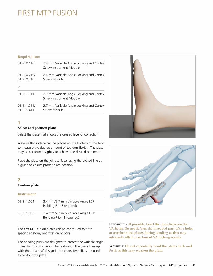
1Select and position plate Select the plate that allows the desired level of correction.
A sterile flat surface can be placed on the bottom of the footto measure the desired amount of toe dorsiflexion. The platemay be contoured slightly to achieve the desired outcome.
Place the plate on the joint surface, using the etched line as a guide to ensure proper plate position.
2 Contour plate
Instrument
03.211.001 2.4 mm/2.7 mm Variable Angle LCP Holding Pin (2 required)
03.211.005 2.4 mm/2.7 mm Variable Angle LCP Bending Plier (2 required)
The first MTP fusion plates can be contou ed to fit th specific anatomy and fixation options
The bending pliers are designed to protect the variable angle holes during contouring. The feature on the pliers lines up with the cloverleaf design in the plate. Two pliers are used to contour the plate.
FIRST MTP FUSION
Precaution: If possible, bend the plate between the VA holes. Do not deform the threaded part of the holes or overbend the plates during bending as this may adversely affect insertion of VA locking screws.
Warning: Do not repeatedly bend the plates back and forth as this may weaken the plate.
42 DePuy Synthes 2.4 mm/2.7 mm Variable Angle LCP® Forefoot/Midfoot System Surgical Technique
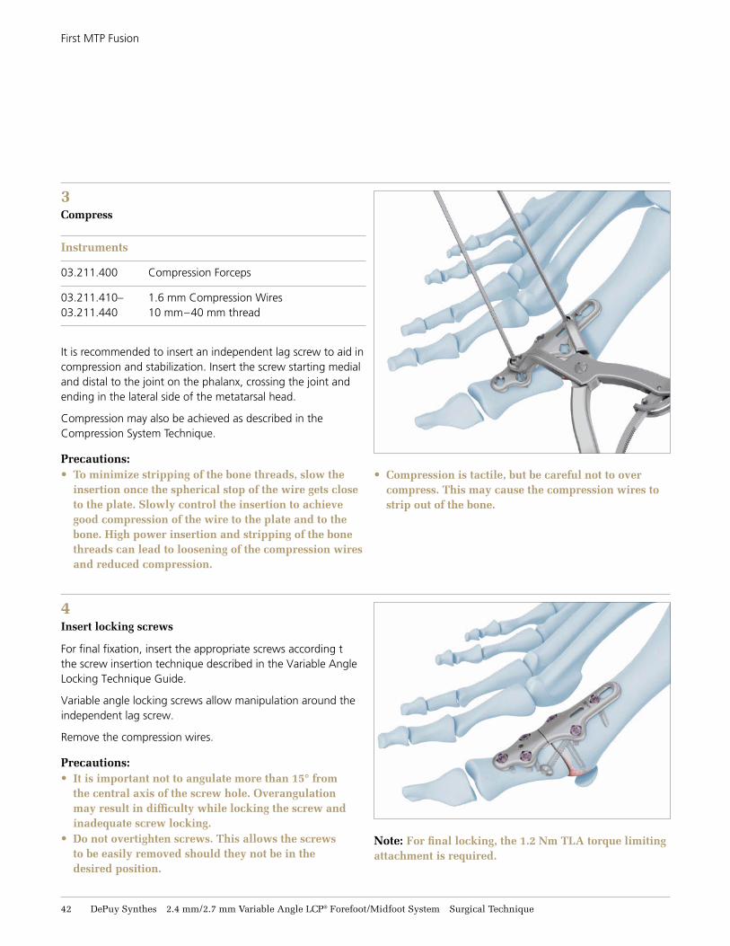
4Insert locking screws
For final fixation, insert the appropriate screws according tthe screw insertion technique described in the Variable Angle Locking Technique Guide.
Variable angle locking screws allow manipulation around the independent lag screw.
Remove the compression wires.
Precautions:• It is important not to angulate more than 15° from
the central axis of the screw hole. Overangulationmay result in difficulty while locking the screw andinadequate screw locking.
• Do not overtighten screws. This allows the screwsto be easily removed should they not be in thedesired position.
First MTP Fusion
3 Compress
Instruments
03.211.400 Compression Forceps
03.211.410– 1.6 mm Compression Wires 03.211.440 10 mm–40 mm thread
It is recommended to insert an independent lag screw to aid in compression and stabilization. Insert the screw starting medial and distal to the joint on the phalanx, crossing the joint and ending in the lateral side of the metatarsal head.
Compression may also be achieved as described in the Compression System Technique.
Precautions:• To minimize stripping of the bone threads, slow the
insertion once the spherical stop of the wire gets closeto the plate. Slowly control the insertion to achievegood compression of the wire to the plate and to thebone. High power insertion and stripping of the bonethreads can lead to loosening of the compression wiresand reduced compression.
• Compression is tactile, but be careful not to overcompress. This may cause the compression wires tostrip out of the bone.
Note: For final locking, the 1.2 Nm TLA torque limiting attachment is required.
2.4 mm/2.7 mm Variable Angle LCP® Forefoot/Midfoot System Surgical Technique DePuy Synthes 43
IMPLANTS
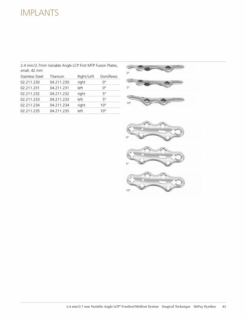
2.4 mm/2.7mm Variable Angle LCP First MTP Fusion Plates, small, 42 mm
Stainless Steel Titanium Right/Left Dorsiflexio
02.211.230 04.211.230 right 0°
02.211.231 04.211.231 left 0°
02.211.232 04.211.232 right 5°
02.211.233 04.211.233 left 5°
02.211.234 04.211.234 right 10°
02.211.235 04.211.235 left 10°
0°
5°
10°
0°
5°
10°
44 DePuy Synthes 2.4 mm/2.7 mm Variable Angle LCP® Forefoot/Midfoot System Surgical Technique
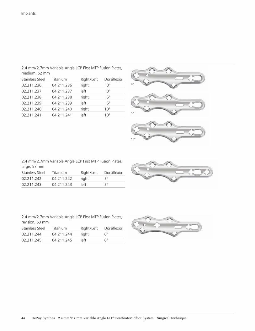
2.4 mm/2.7mm Variable Angle LCP First MTP Fusion Plates, medium, 52 mm
Stainless Steel Titanium Right/Left Dorsiflexio
02.211.236 04.211.236 right 0°
02.211.237 04.211.237 left 0°
02.211.238 04.211.238 right 5°
02.211.239 04.211.239 left 5°
02.211.240 04.211.240 right 10°
02.211.241 04.211.241 left 10°
Implants
0°
5°
10°
2.4 mm/2.7mm Variable Angle LCP First MTP Fusion Plates, large, 57 mm
Stainless Steel Titanium Right/Left Dorsiflexio
02.211.242 04.211.242 right 5°
02.211.243 04.211.243 left 5°
2.4 mm/2.7mm Variable Angle LCP First MTP Fusion Plates, revision, 53 mm
Stainless Steel Titanium Right/Left Dorsiflexio
02.211.244 04.211.244 right 0°
02.211.245 04.211.245 left 0°
OPENING WEDGE OSTEOTOMY FOR CORRECTION OF HALLUX VALGUS
Opening W
edge Osteotom
y for C
orrection of H
allux Valgus
2.4 mm/2.7 mm Variable Angle LCP® Forefoot/Midfoot System Surgical Technique DePuy Synthes 45
OPENING WEDGE OSTEOTOMY FOR CORRECTION OF HALLUX VALGUS
Required sets
01.210.110 2.4 mm Variable Angle Locking and Cortex Screw Instrument Module
01.210.210/ 2.4 mm Variable Angle Locking and Cortex 01.210.410 Screw Module (stainless steel or titanium)
or
01.211.111 2.7 mm Variable Angle Locking and Cortex Screw Instrument Module
01.211.211/ 2.7 mm Variable Angle Locking and Cortex 01.211.411 Screw Module (stainless steel or titanium)
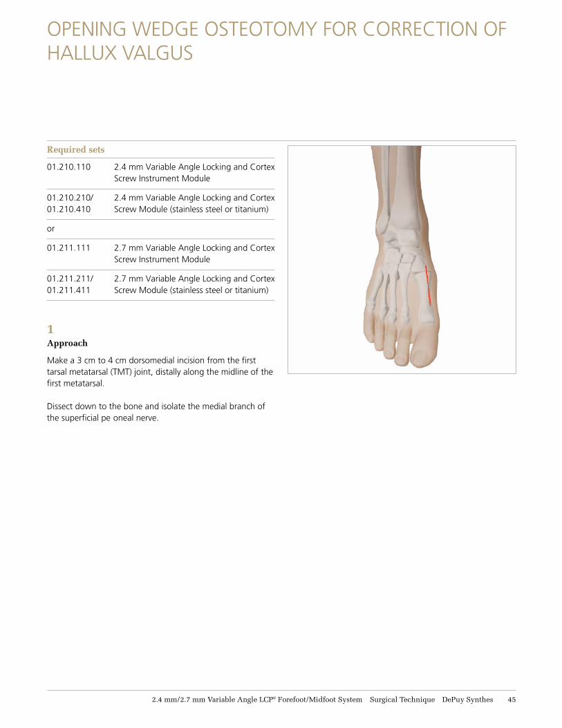
1 Approach
Make a 3 cm to 4 cm dorsomedial incision from the first tarsal metatarsal (TMT) joint, distally along the midline of the first metatarsal.
Dissect down to the bone and isolate the medial branch of the superficial pe oneal nerve.
46 DePuy Synthes 2.4 mm/2.7 mm Variable Angle LCP® Forefoot/Midfoot System Surgical Technique
Opening Wedge Osteotomy for Correction of Hallux Valgus
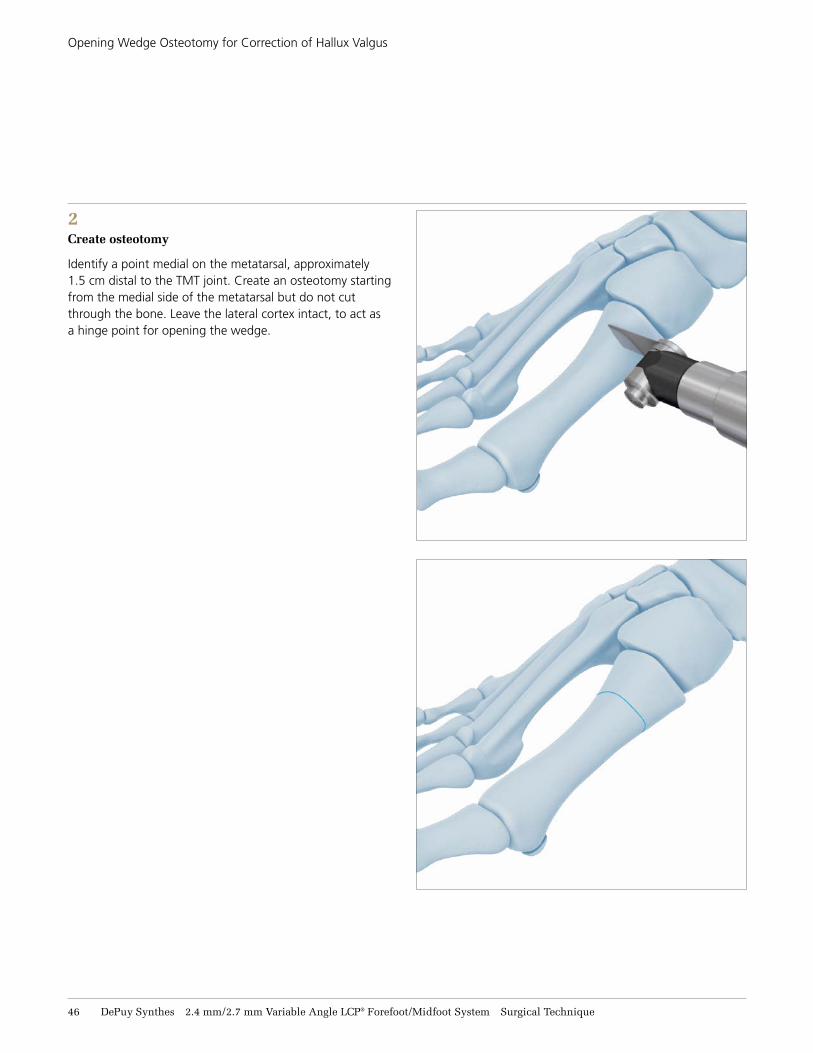
2Create osteotomy
Identify a point medial on the metatarsal, approximately 1.5 cm distal to the TMT joint. Create an osteotomy starting from the medial side of the metatarsal but do not cut through the bone. Leave the lateral cortex intact, to act as a hinge point for opening the wedge.
2.4 mm/2.7 mm Variable Angle LCP® Forefoot/Midfoot System Surgical Technique DePuy Synthes 47
Opening Wedge Osteotomy for Correction of Hallux Valgus
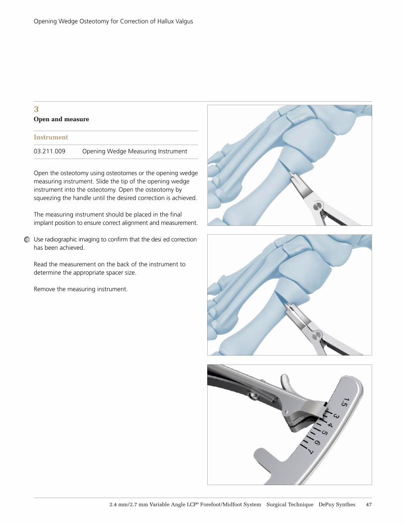
3 Open and measure
Instrument
03.211.009 Opening Wedge Measuring Instrument
Open the osteotomy using osteotomes or the opening wedge measuring instrument. Slide the tip of the opening wedge instrument into the osteotomy. Open the osteotomy by squeezing the handle until the desired correction is achieved.
The measuring instrument should be placed in the final implant position to ensure correct alignment and measurement.
Use radiographic imaging to confirm that the desi ed correction has been achieved.
Read the measurement on the back of the instrument to determine the appropriate spacer size. Remove the measuring instrument.
48 DePuy Synthes 2.4 mm/2.7 mm Variable Angle LCP® Forefoot/Midfoot System Surgical Technique
Opening Wedge Osteotomy for Correction of Hallux Valgus
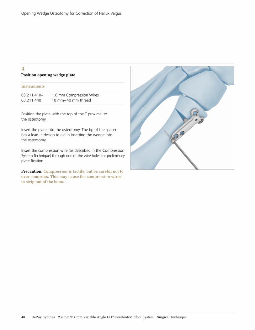
4 Position opening wedge plate
Instruments
03.211.410– 1.6 mm Compression Wires 03.211.440 10 mm–40 mm thread
Position the plate with the top of the T proximal to the osteotomy.
Insert the plate into the osteotomy. The tip of the spacer has a lead-in design to aid in inserting the wedge into the osteotomy.
Insert the compression wire (as described in the Compression System Technique) through one of the wire holes for preliminary plate fixation.
Precaution: Compression is tactile, but be careful not to over compress. This may cause the compression wires to strip out of the bone.
2.4 mm/2.7 mm Variable Angle LCP® Forefoot/Midfoot System Surgical Technique DePuy Synthes 49
Opening Wedge Osteotomy for Correction of Hallux Valgus
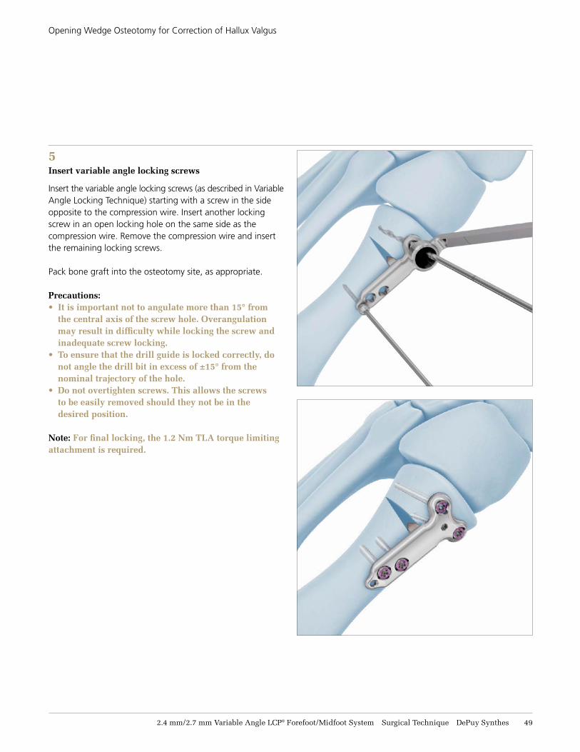
5 Insert variable angle locking screws
Insert the variable angle locking screws (as described in Variable Angle Locking Technique) starting with a screw in the side opposite to the compression wire. Insert another locking screw in an open locking hole on the same side as the compression wire. Remove the compression wire and insert the remaining locking screws.
Pack bone graft into the osteotomy site, as appropriate.
Precautions:• It is important not to angulate more than 15° from
the central axis of the screw hole. Overangulation may result in difficulty while locking the screw and inadequate screw locking.
• To ensure that the drill guide is locked correctly, do not angle the drill bit in excess of ±15° from the nominal trajectory of the hole.
• Do not overtighten screws. This allows the screws to be easily removed should they not be in the desired position.
Note: For final locking, the 1.2 Nm TLA torque limiting attachment is required.
51 DePuy Synthes 2.4 mm/2.7 mm Variable Angle LCP® Forefoot/Midfoot System Surgical Technique
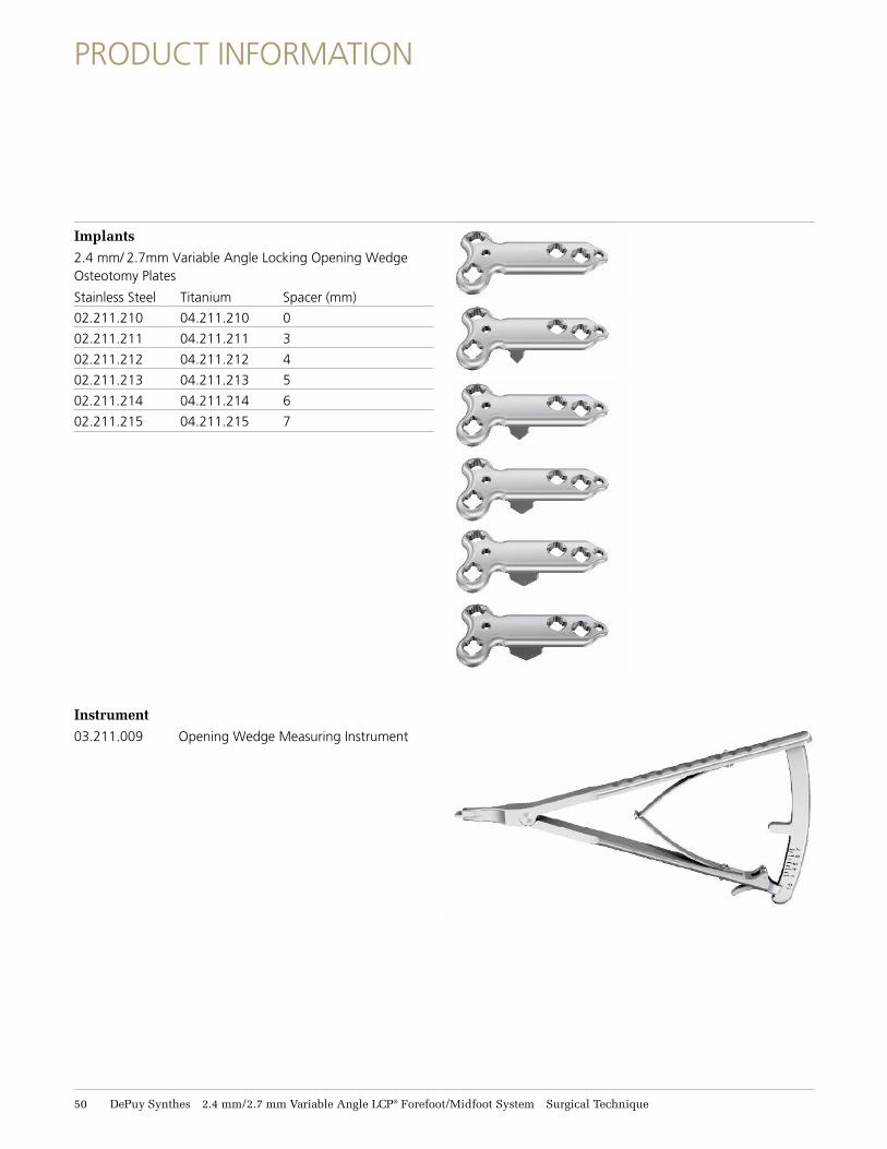
PRODUCT INFORMATION
Implants2.4 mm/ 2.7mm Variable Angle Locking Opening Wedge Osteotomy Plates
Stainless Steel Titanium Spacer (mm)
02.211.210 04.211.210 0
02.211.211 04.211.211 3
02.211.212 04.211.212 4
02.211.213 04.211.213 5
02.211.214 04.211.214 6
02.211.215 04.211.215 7
Instrument03.211.009 Opening Wedge Measuring Instrument
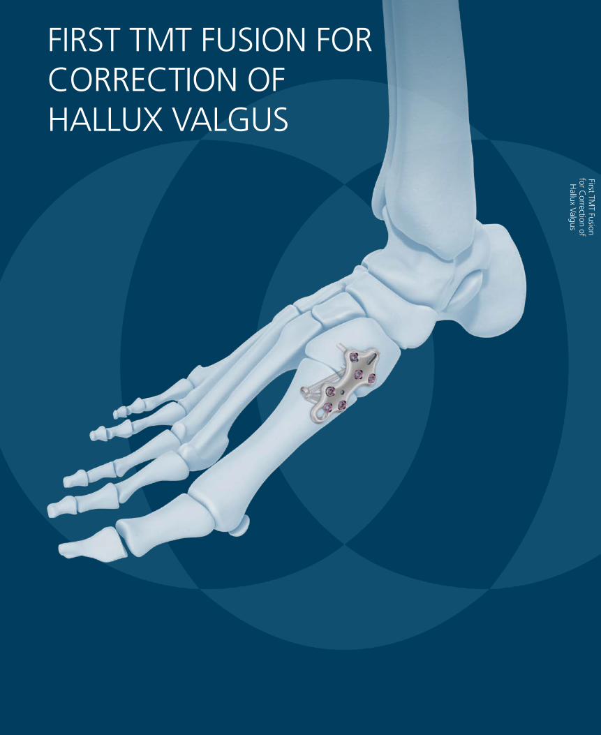
First TMT Fusion
for Correction of
Hallux Valgus
FIRST TMT FUSION FOR CORRECTION OF HALLUX VALGUS
2.4 mm/2.7 mm Variable Angle LCP® Forefoot/Midfoot System Surgical Technique DePuy Synthes 51
FIRST TMT FUSION FOR CORRECTION OF HALLUX VALGUS
Required sets
01.210.110 2.4 mm Variable Angle Locking and Cortex Screw Instrument Module
01.210.210/ 2.4 mm Variable Angle Locking and Cortex 01.210.410 Screw Module (stainless steel or titanium)
or
01.211.111 2.7 mm Variable Angle Locking and Cortex Screw Instrument Module
01.211.211/ 2.7 mm Variable Angle Locking and Cortex 01.211.411 Screw Module (stainless steel or titanium)
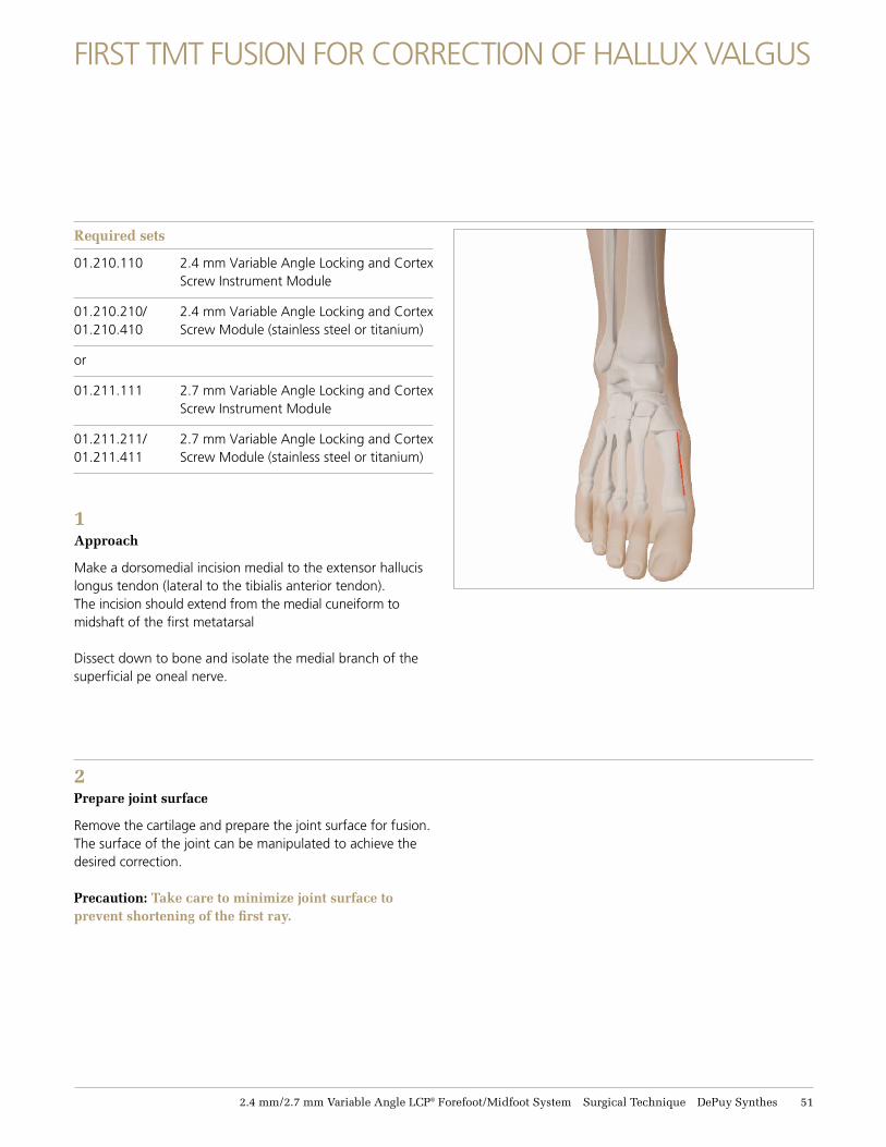
1Approach
Make a dorsomedial incision medial to the extensor hallucis longus tendon (lateral to the tibialis anterior tendon). The incision should extend from the medial cuneiform to midshaft of the first metatarsal
Dissect down to bone and isolate the medial branch of the superficial pe oneal nerve.
2Prepare joint surface
Remove the cartilage and prepare the joint surface for fusion. The surface of the joint can be manipulated to achieve the desired correction.
Precaution: Take care to minimize joint surface to prevent shortening of the first ray.
52 DePuy Synthes 2.4 mm/2.7 mm Variable Angle LCP® Forefoot/Midfoot System Surgical Technique
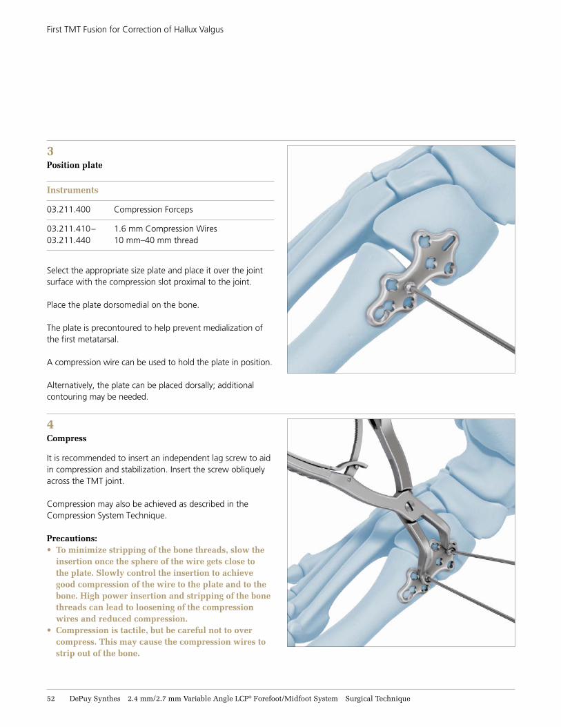
4 Compress
It is recommended to insert an independent lag screw to aid in compression and stabilization. Insert the screw obliquely across the TMT joint.
Compression may also be achieved as described in the Compression System Technique.
Precautions:• To minimize stripping of the bone threads, slow the
insertion once the sphere of the wire gets close to the plate. Slowly control the insertion to achieve good compression of the wire to the plate and to the bone. High power insertion and stripping of the bone threads can lead to loosening of the compression wires and reduced compression.
• Compression is tactile, but be careful not to over compress. This may cause the compression wires to strip out of the bone.
First TMT Fusion for Correction of Hallux Valgus
3Position plate
Instruments
03.211.400 Compression Forceps
03.211.410– 1.6 mm Compression Wires 03.211.440 10 mm–40 mm thread
Select the appropriate size plate and place it over the joint surface with the compression slot proximal to the joint.
Place the plate dorsomedial on the bone.
The plate is precontoured to help prevent medialization of the first metatarsal.
A compression wire can be used to hold the plate in position.
Alternatively, the plate can be placed dorsally; additional contouring may be needed.
2.4 mm/2.7 mm Variable Angle LCP® Forefoot/Midfoot System Surgical Technique DePuy Synthes 53
First TMT Fusion for Correction of Hallux Valgus
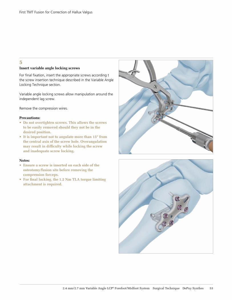
5Insert variable angle locking screws
For final fixation, insert the appropriate screws according tthe screw insertion technique described in the Variable Angle Locking Technique section.
Variable angle locking screws allow manipulation around the independent lag screw.
Remove the compression wires.
Precautions:• Do not overtighten screws. This allows the screws
to be easily removed should they not be in the desired position.
• It is important not to angulate more than 15° from the central axis of the screw hole. Overangulation may result in difficulty while locking the screw and inadequate screw locking.
Notes:• Ensure a screw is inserted on each side of the
osteotomy/fusion site before removing the compression forceps.
• For final locking, the 1.2 Nm TLA torque limiting attachment is required.
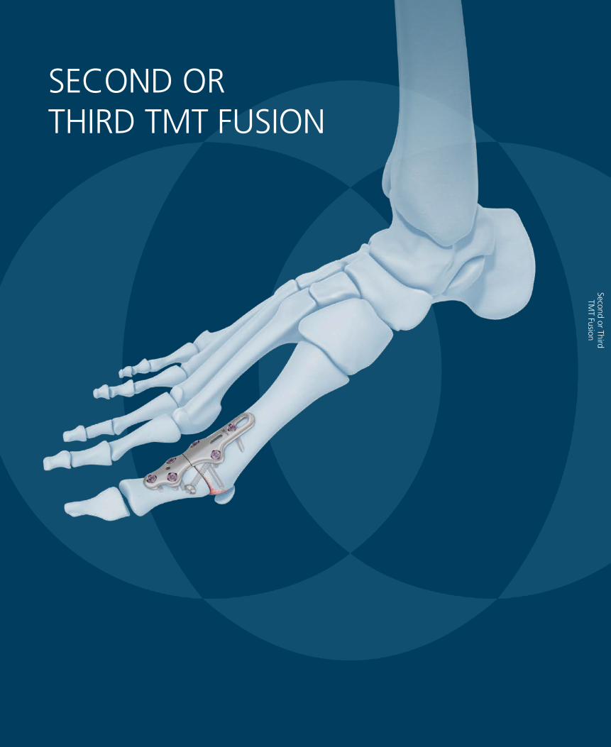
SECOND OR THIRD TMT FUSION
Second or Third TM
T Fusion
2.4 mm/2.7 mm Variable Angle LCP® Forefoot/Midfoot System Surgical Technique DePuy Synthes 55
SECOND OR THIRD TMT FUSION
Required sets
01.210.110 2.4 mm Variable Angle Locking and Cortex Screw Instrument Module
01.210.210/ 2.4 mm Variable Angle Locking and Cortex 01.210.410 Screw Module (stainless steel or titanium)
or
01.211.111 2.7 mm Variable Angle Locking and Cortex Screw Instrument Module
01.211.211/ 2.7 mm Variable Angle Locking and Cortex 01.211.411 Screw Module (stainless steel or titanium)
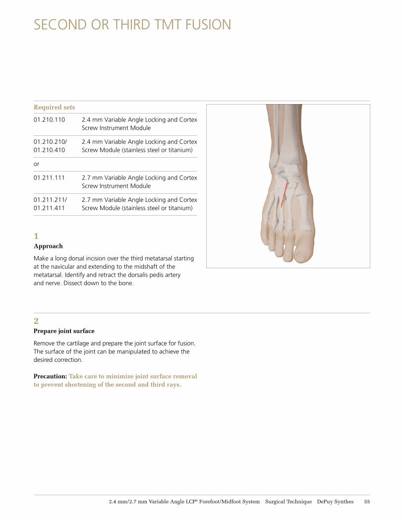
1 Approach
Make a long dorsal incision over the third metatarsal starting at the navicular and extending to the midshaft of the metatarsal. Identify and retract the dorsalis pedis artery and nerve. Dissect down to the bone.
2Prepare joint surface
Remove the cartilage and prepare the joint surface for fusion. The surface of the joint can be manipulated to achieve the desired correction.
Precaution: Take care to minimize joint surface removal to prevent shortening of the second and third rays.
56 DePuy Synthes 2.4 mm/2.7 mm Variable Angle LCP® Forefoot/Midfoot System Surgical Technique
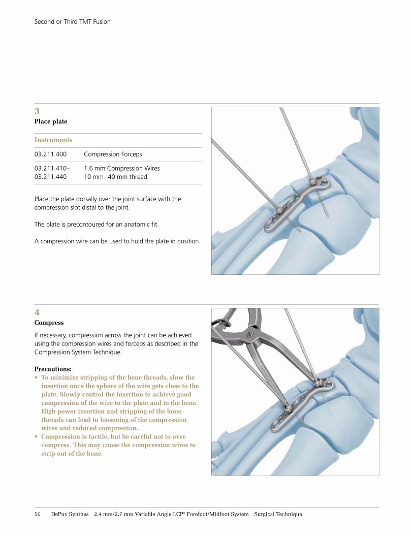
4Compress
If necessary, compression across the joint can be achieved using the compression wires and forceps as described in the Compression System Technique.
Precautions:• To minimize stripping of the bone threads, slow the
insertion once the sphere of the wire gets close to the plate. Slowly control the insertion to achieve good compression of the wire to the plate and to the bone. High power insertion and stripping of the bone threads can lead to loosening of the compression wires and reduced compression.
• Compression is tactile, but be careful not to over compress. This may cause the compression wires to strip out of the bone.
Second or Third TMT Fusion
3 Place plate
Instruments
03.211.400 Compression Forceps
03.211.410– 1.6 mm Compression Wires 03.211.440 10 mm–40 mm thread
Place the plate dorsally over the joint surface with the compression slot distal to the joint.
The plate is precontoured for an anatomic fit.
A compression wire can be used to hold the plate in position.
2.4 mm/2.7 mm Variable Angle LCP® Forefoot/Midfoot System Surgical Technique DePuy Synthes 57
Second or Third TMT Fusion
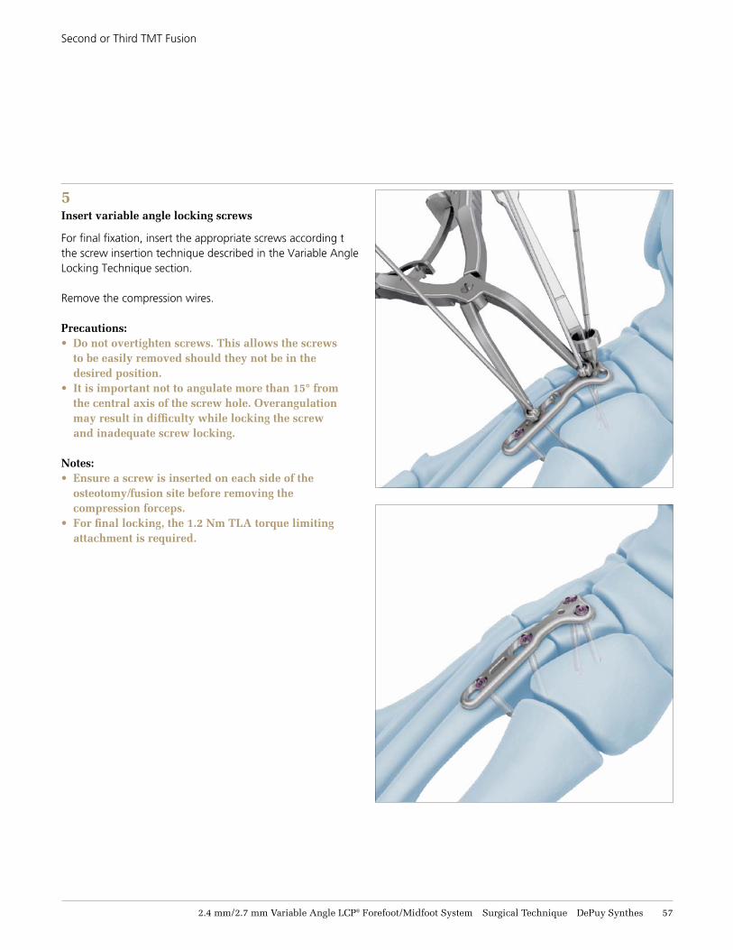
5Insert variable angle locking screws
For final fixation, insert the appropriate screws according tthe screw insertion technique described in the Variable Angle Locking Technique section.
Remove the compression wires.
Precautions: • Do not overtighten screws. This allows the screws
to be easily removed should they not be in the desired position.
• It is important not to angulate more than 15° from the central axis of the screw hole. Overangulation may result in difficulty while locking the screw and inadequate screw locking.
Notes:• Ensure a screw is inserted on each side of the
osteotomy/fusion site before removing the compression forceps.
• For final locking, the 1.2 Nm TLA torque limiting attachment is required.
58 DePuy Synthes 2.4 mm/2.7 mm Variable Angle LCP® Forefoot/Midfoot System Surgical Technique
IMPLANTS
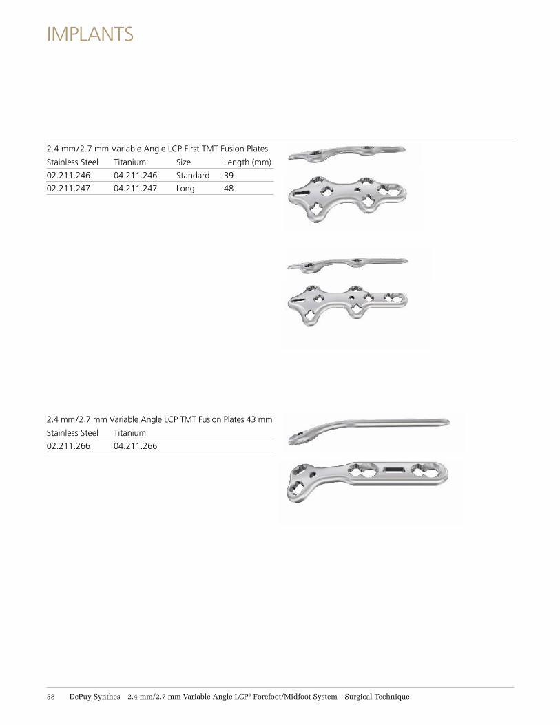
2.4 mm/2.7 mm Variable Angle LCP First TMT Fusion Plates
Stainless Steel Titanium Size Length (mm)
02.211.246 04.211.246 Standard 39
02.211.247 04.211.247 Long 48
2.4 mm/2.7 mm Variable Angle LCP TMT Fusion Plates 43 mm
Stainless Steel Titanium
02.211.266 04.211.266
Navicular and
Cuboid Fractures
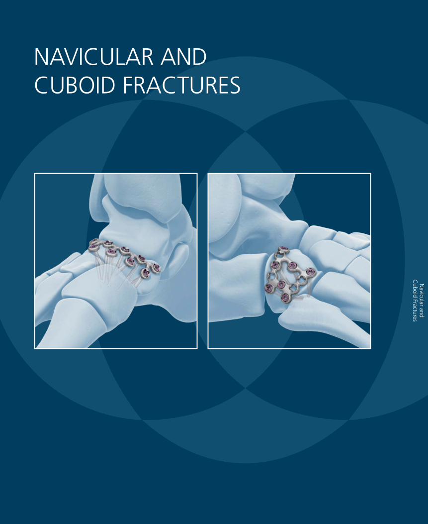
NAVICULAR AND CUBOID FRACTURES
2.4 mm/2.7 mm Variable Angle LCP® Forefoot/Midfoot System Surgical Technique DePuy Synthes 59
NAVICULAR AND CUBOID FRACTURES
Required sets
01.210.110 2.4 mm Variable Angle Locking and Cortex Screw Instrument Module
01.210.210/ 2.4 mm Variable Angle Locking and Cortex 01.210.410 Screw Module (stainless steel or titanium)
or
01.211.111 2.7 mm Variable Angle Locking and Cortex Screw Instrument Module
01.211.211/ 2.7 mm Variable Angle Locking and Cortex 01.211.411 Screw Module (stainless steel or titanium)
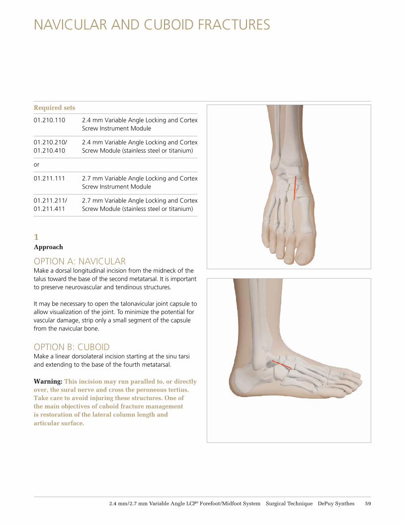
1 Approach
OPTION A: NAVICULARMake a dorsal longitudinal incision from the midneck of the talus toward the base of the second metatarsal. It is important to preserve neurovascular and tendinous structures.
It may be necessary to open the talonavicular joint capsule to allow visualization of the joint. To minimize the potential for vascular damage, strip only a small segment of the capsule from the navicular bone.
OPTION B: CUBOID Make a linear dorsolateral incision starting at the sinu tarsi and extending to the base of the fourth metatarsal.
Warning: This incision may run paralled to, or directly over, the sural nerve and cross the peroneous tertius. Take care to avoid injuring these structures. One of the main objectives of cuboid fracture management is restoration of the lateral column length and articular surface.
61 DePuy Synthes 2.4 mm/2.7 mm Variable Angle LCP® Forefoot/Midfoot System Surgical Technique
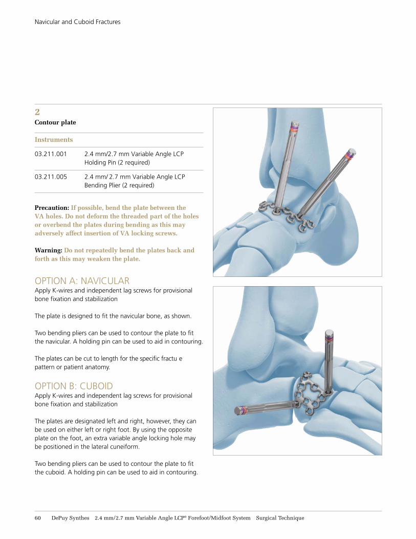
Navicular and Cuboid Fractures
2Contour plate Instruments
03.211.001 2.4 mm/2.7 mm Variable Angle LCP Holding Pin (2 required)
03.211.005 2.4 mm/ 2.7 mm Variable Angle LCP Bending Plier (2 required)
Precaution: If possible, bend the plate between the VA holes. Do not deform the threaded part of the holes or overbend the plates during bending as this may adversely affect insertion of VA locking screws.
Warning: Do not repeatedly bend the plates back and forth as this may weaken the plate.
OPTION A: NAVICULARApply K-wires and independent lag screws for provisional bone fixation and stabilization
The plate is designed to fit the navicular bone, as shown.
Two bending pliers can be used to contour the plate to fitthe navicular. A holding pin can be used to aid in contouring.
The plates can be cut to length for the specific fractu e pattern or patient anatomy.
OPTION B: CUBOIDApply K-wires and independent lag screws for provisional bone fixation and stabilization
The plates are designated left and right, however, they can be used on either left or right foot. By using the opposite plate on the foot, an extra variable angle locking hole may be positioned in the lateral cuneiform.
Two bending pliers can be used to contour the plate to fitthe cuboid. A holding pin can be used to aid in contouring.
2.4 mm/2.7 mm Variable Angle LCP® Forefoot/Midfoot System Surgical Technique DePuy Synthes 61
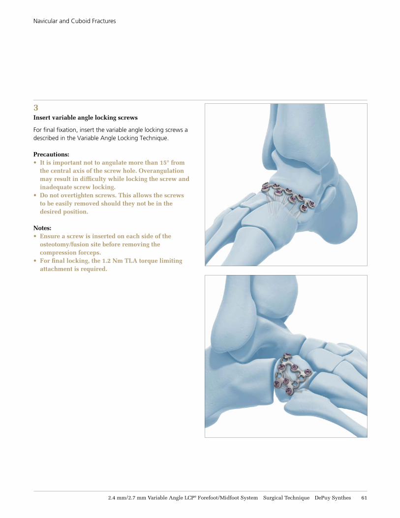
Navicular and Cuboid Fractures
3 Insert variable angle locking screws
For final fixation, insert the variable angle locking screws adescribed in the Variable Angle Locking Technique.
Precautions:• It is important not to angulate more than 15° from
the central axis of the screw hole. Overangulation may result in difficulty while locking the screw and inadequate screw locking.
• Do not overtighten screws. This allows the screws to be easily removed should they not be in the desired position.
Notes:• Ensure a screw is inserted on each side of the
osteotomy/fusion site before removing the compression forceps.
• For final locking, the 1.2 Nm TLA torque limiting attachment is required.
62 DePuy Synthes 2.4 mm/2.7 mm Variable Angle LCP® Forefoot/Midfoot System Surgical Technique
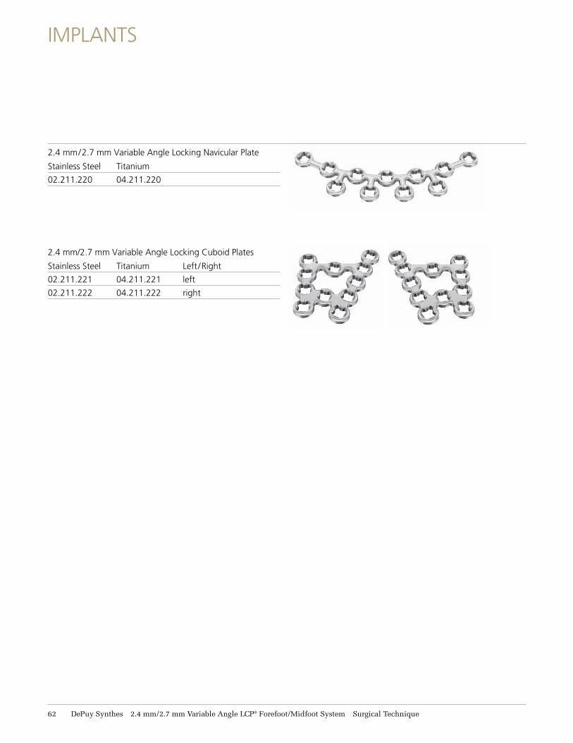
IMPLANTS
2.4 mm/2.7 mm Variable Angle Locking Navicular Plate
Stainless Steel Titanium
02.211.220 04.211.220
2.4 mm/2.7 mm Variable Angle Locking Cuboid Plates
Stainless Steel Titanium Left /Right
02.211.221 04.211.221 left
02.211.222 04.211.222 right
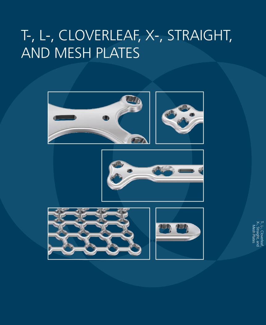
T-, L-, CLOVERLEAF, X-, STRAIGHT, AND MESH PLATES
T-, L-, Cloverleaf,
X-, Straight, and M
esh Plates
2.4 mm/2.7 mm Variable Angle LCP® Forefoot/Midfoot System Surgical Technique DePuy Synthes 63
T-, L-, CLOVERLEAF, X-, STRAIGHT, AND MESH PLATES
Required sets
01.210.110 2.4 mm Variable Angle Locking and Cortex Screw Instrument Module
01.210.210/ 2.4 mm Variable Angle Locking and Cortex 01.210.410 Screw Module (stainless steel or titanium)
or
01.211.111 2.7 mm Variable Angle Locking and Cortex Screw Instrument Module
01.211.211/ 2.7 mm Variable Angle Locking and Cortex 01.211.411 Screw Module (stainless steel or titanium)
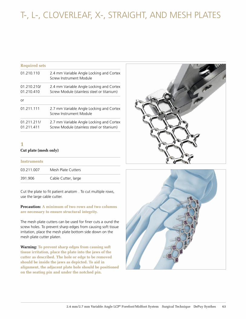
1 Cut plate (mesh only)
Instruments
03.211.007 Mesh Plate Cutters
391.906 Cable Cutter, large
Cut the plate to fit patient anatom . To cut multiple rows, use the large cable cutter.
Precaution: A minimum of two rows and two columns are necessary to ensure structural integrity.
The mesh plate cutters can be used for finer cuts a ound the screw holes. To prevent sharp edges from causing soft tissue irritation, place the mesh plate bottom side down on the mesh plate cutter platen.
Warning: To prevent sharp edges from causing soft tissue irritation, place the plate into the jaws of the cutter as described. The hole or edge to be removed should be inside the jaws as depicted. To aid in alignment, the adjacent plate hole should be positioned on the seating pin and under the notched pin.
64 DePuy Synthes 2.4 mm/2.7 mm Variable Angle LCP® Forefoot/Midfoot System Surgical Technique
T-, L-, Cloverleaf, X-, Straight, and Mesh Plates
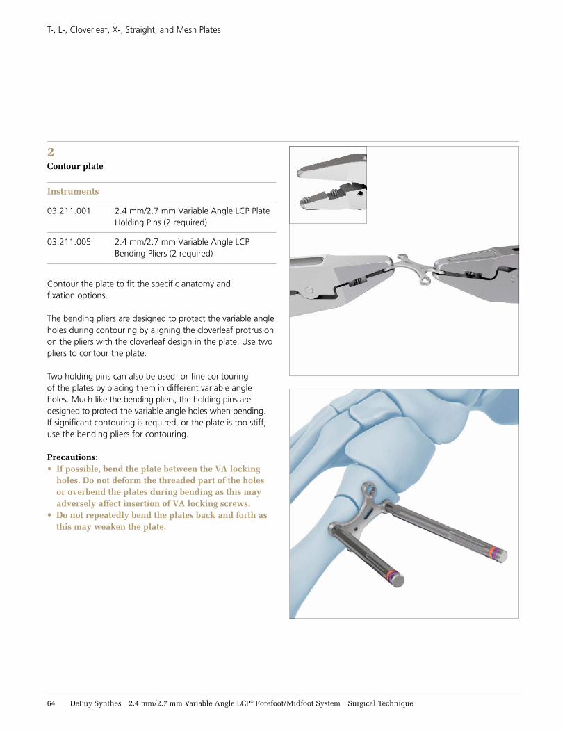
2Contour plate
Instruments
03.211.001 2.4 mm/2.7 mm Variable Angle LCP Plate Holding Pins (2 required)
03.211.005 2.4 mm/2.7 mm Variable Angle LCP Bending Pliers (2 required)
Contour the plate to fit the specific anatomy and fixation options.
The bending pliers are designed to protect the variable angle holes during contouring by aligning the cloverleaf protrusion on the pliers with the cloverleaf design in the plate. Use two pliers to contour the plate.
Two holding pins can also be used for fine contouring of the plates by placing them in different variable angle holes. Much like the bending pliers, the holding pins are designed to protect the variable angle holes when bending. If significant contouring is required, or the plate is too stiff, use the bending pliers for contouring.
Precautions:• If possible, bend the plate between the VA locking
holes. Do not deform the threaded part of the holes or overbend the plates during bending as this may adversely affect insertion of VA locking screws.
• Do not repeatedly bend the plates back and forth as this may weaken the plate.
2.4 mm/2.7 mm Variable Angle LCP® Forefoot/Midfoot System Surgical Technique DePuy Synthes 65
T-, L-, Cloverleaf, X-, Straight, and Mesh Plates
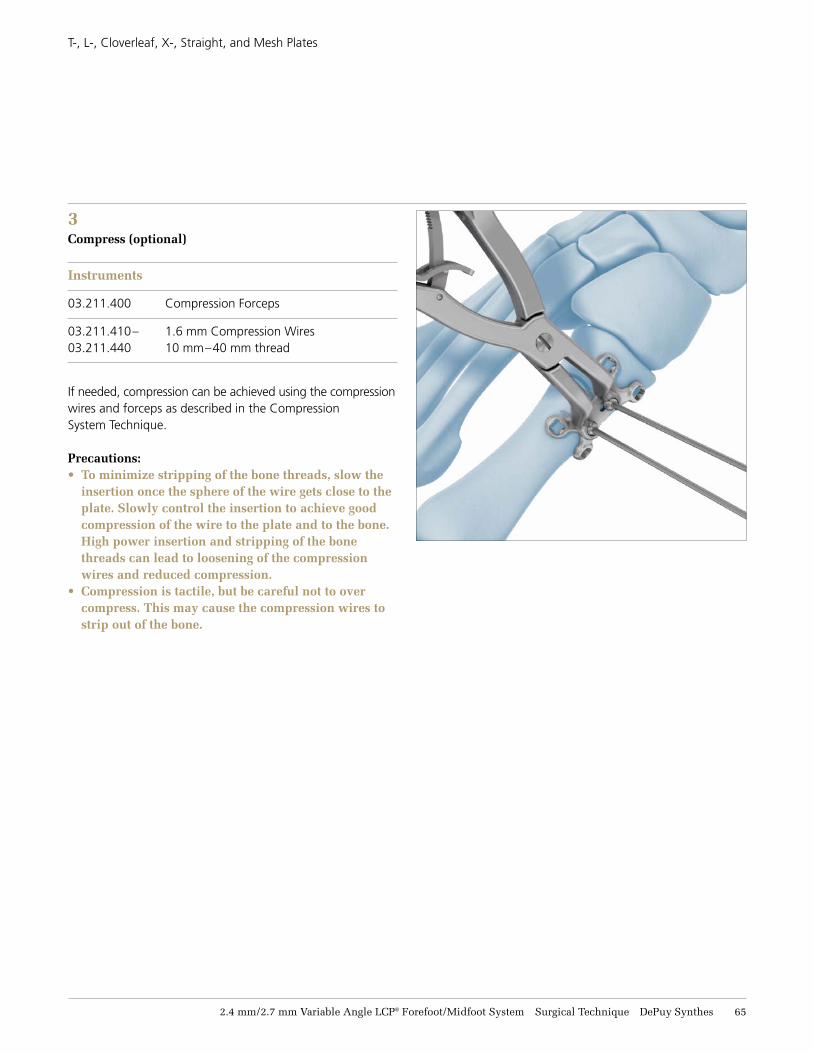
3 Compress (optional)
Instruments
03.211.400 Compression Forceps
03.211.410– 1.6 mm Compression Wires 03.211.440 10 mm–40 mm thread
If needed, compression can be achieved using the compression wires and forceps as described in the Compression System Technique.
Precautions:• To minimize stripping of the bone threads, slow the
insertion once the sphere of the wire gets close to the plate. Slowly control the insertion to achieve good compression of the wire to the plate and to the bone. High power insertion and stripping of the bone threads can lead to loosening of the compression wires and reduced compression.
• Compression is tactile, but be careful not to over compress. This may cause the compression wires to strip out of the bone.
66 DePuy Synthes 2.4 mm/2.7 mm Variable Angle LCP® Forefoot/Midfoot System Surgical Technique
T-, L-, Cloverleaf, X-, Straight, and Mesh Plates
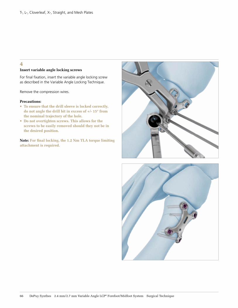
4 Insert variable angle locking screws
For final fixation, insert the variable angle locking screw as described in the Variable Angle Locking Technique. Remove the compression wires.
Precautions:• To ensure that the drill sleeve is locked correctly,
do not angle the drill bit in excess of +/- 15° from the nominal trajectory of the hole.
• Do not overtighten screws. This allows for the screws to be easily removed should they not be in the desired position.
Note: For final locking, the 1.2 Nm TLA torque limiting attachment is required.
2.4 mm/2.7 mm Variable Angle LCP® Forefoot/Midfoot System Surgical Technique DePuy Synthes 67
IMPLANTS
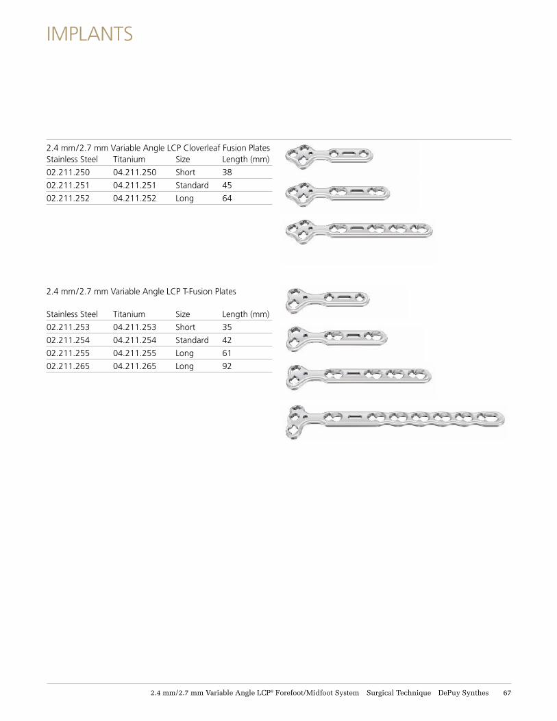
2.4 mm/2.7 mm Variable Angle LCP Cloverleaf Fusion Plates Stainless Steel Titanium Size Length (mm)
02.211.250 04.211.250 Short 38
02.211.251 04.211.251 Standard 45
02.211.252 04.211.252 Long 64
2.4 mm/2.7 mm Variable Angle LCP T-Fusion Plates
Stainless Steel Titanium Size Length (mm)
02.211.253 04.211.253 Short 35
02.211.254 04.211.254 Standard 42
02.211.255 04.211.255 Long 61
02.211.265 04.211.265 Long 92
68 DePuy Synthes 2.4 mm/2.7 mm Variable Angle LCP® Forefoot/Midfoot System Surgical Technique
Implants
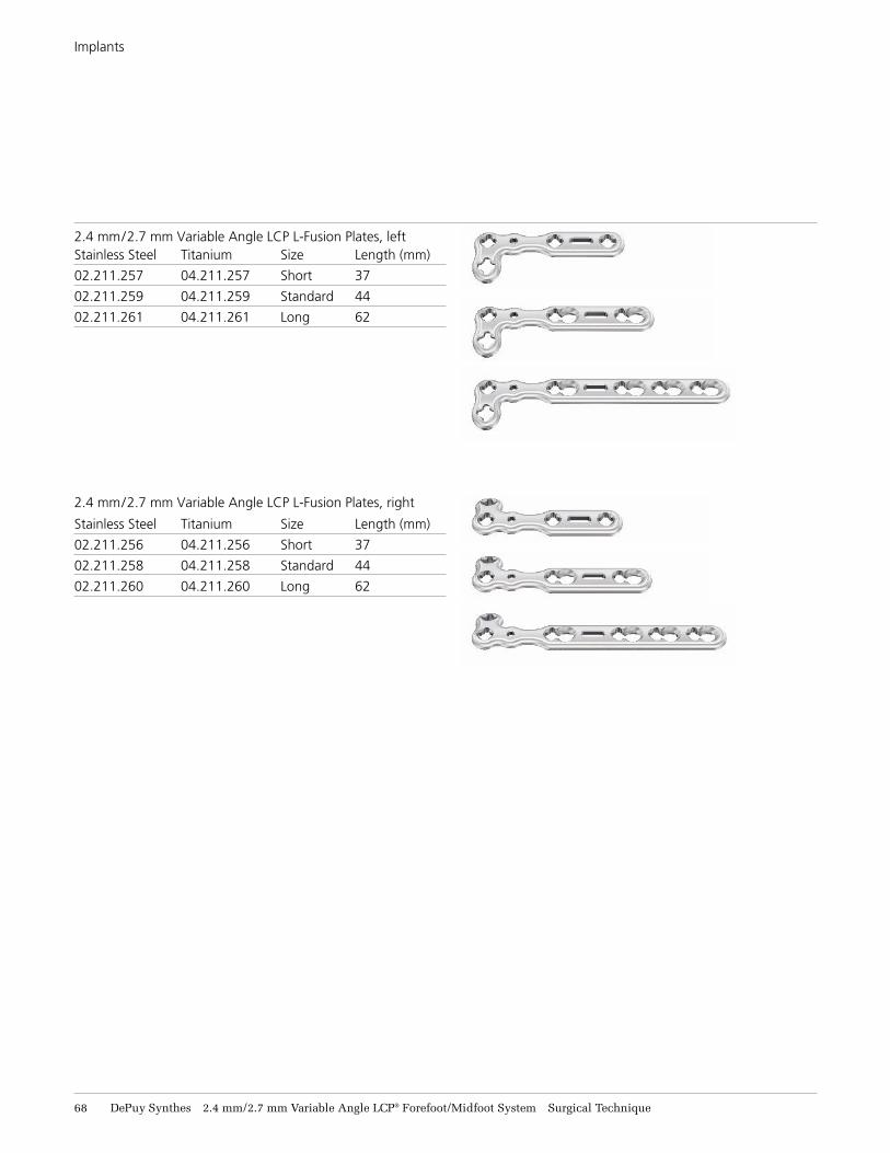
2.4 mm/2.7 mm Variable Angle LCP L-Fusion Plates, left Stainless Steel Titanium Size Length (mm)
02.211.257 04.211.257 Short 37
02.211.259 04.211.259 Standard 44
02.211.261 04.211.261 Long 62
2.4 mm/2.7 mm Variable Angle LCP L-Fusion Plates, right
Stainless Steel Titanium Size Length (mm)
02.211.256 04.211.256 Short 37
02.211.258 04.211.258 Standard 44
02.211.260 04.211.260 Long 62
2.4 mm/2.7 mm Variable Angle LCP® Forefoot/Midfoot System Surgical Technique DePuy Synthes 69
Implants
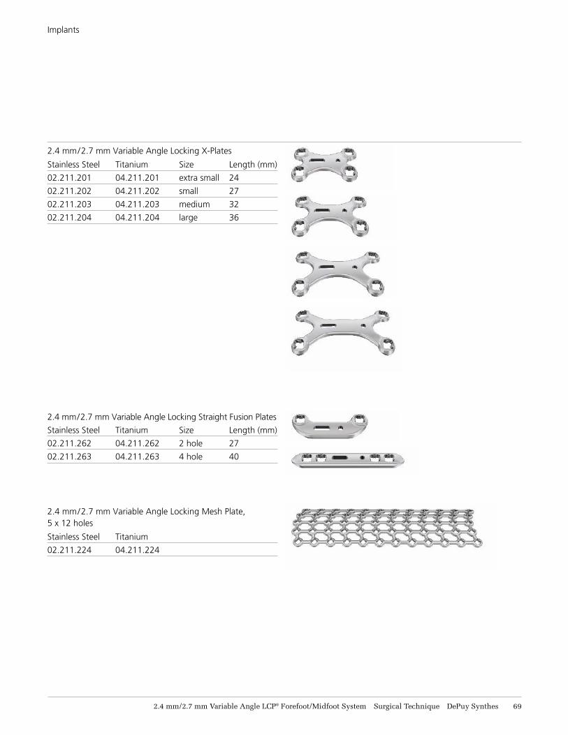
2.4 mm/2.7 mm Variable Angle Locking X-Plates
Stainless Steel Titanium Size Length (mm)
02.211.201 04.211.201 extra small 24
02.211.202 04.211.202 small 27
02.211.203 04.211.203 medium 32
02.211.204 04.211.204 large 36
2.4 mm/2.7 mm Variable Angle Locking Straight Fusion Plates
Stainless Steel Titanium Size Length (mm)
02.211.262 04.211.262 2 hole 27
02.211.263 04.211.263 4 hole 40
2.4 mm/2.7 mm Variable Angle Locking Mesh Plate, 5 x 12 holes
Stainless Steel Titanium
02.211.224 04.211.224
71 DePuy Synthes 2.4 mm/2.7 mm Variable Angle LCP® Forefoot/Midfoot System Surgical Technique
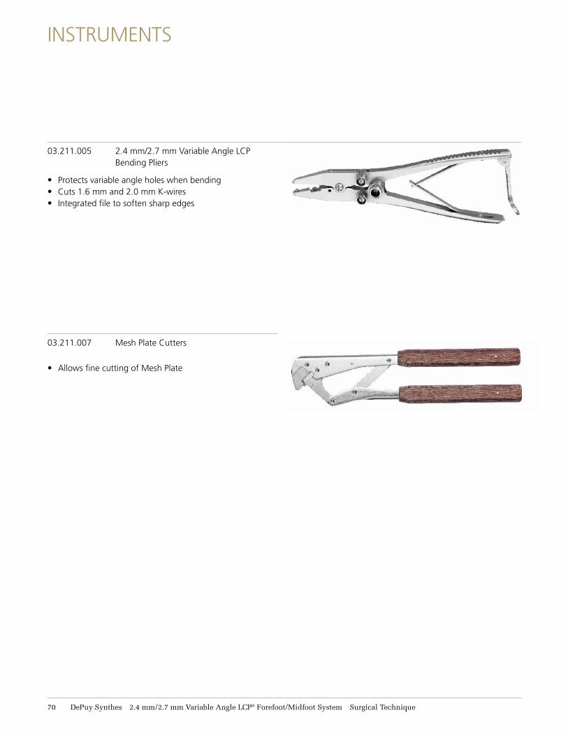
INSTRUMENTS
03.211.005 2.4 mm/2.7 mm Variable Angle LCP Bending Pliers
• Protects variable angle holes when bending • Cuts 1.6 mm and 2.0 mm K-wires • Integrated file to soften sharp edges
03.211.007 Mesh Plate Cutters
• Allows fine cutting of Mesh Plate
SET CONFIGURATIONS
Set C
onfiguration
2.4 mm/2.7 mm Variable Angle LCP® Forefoot/Midfoot System Surgical Technique DePuy Synthes 71
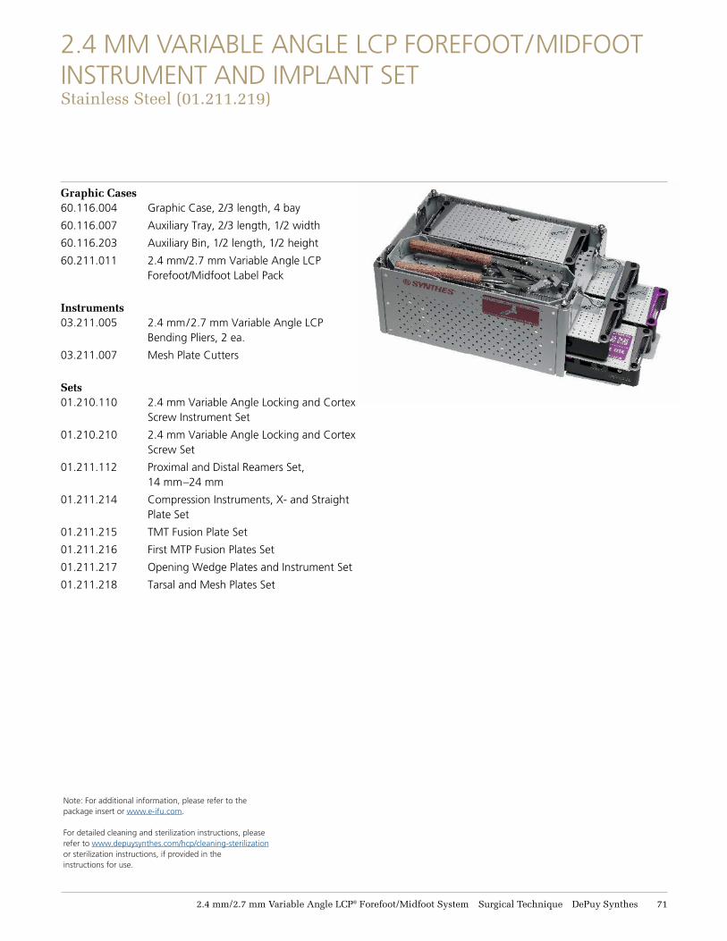
2.4 MM VARIABLE ANGLE LCP FOREFOOT/MIDFOOT INSTRUMENT AND IMPLANT SET Stainless Steel (11.211.219)
Graphic Cases 60.116.004 Graphic Case, 2/3 length, 4 bay
60.116.007 Auxiliary Tray, 2/3 length, 1/2 width
60.116.203 Auxiliary Bin, 1/2 length, 1/2 height
60.211.011 2.4 mm/2.7 mm Variable Angle LCP Forefoot/Midfoot Label Pack
Instruments 03.211.005 2.4 mm/2.7 mm Variable Angle LCP
Bending Pliers, 2 ea.
03.211.007 Mesh Plate Cutters
Sets01.210.110 2.4 mm Variable Angle Locking and Cortex
Screw Instrument Set
01.210.210 2.4 mm Variable Angle Locking and Cortex Screw Set
01.211.112 Proximal and Distal Reamers Set, 14 mm–24 mm
01.211.214 Compression Instruments, X- and Straight Plate Set
01.211.215 TMT Fusion Plate Set
01.211.216 First MTP Fusion Plates Set
01.211.217 Opening Wedge Plates and Instrument Set
01.211.218 Tarsal and Mesh Plates Set
Note: For additional information, please refer to the package insert or www.e-ifu.com.
For detailed cleaning and sterilization instructions, please refer to www.depuysynthes.com/hcp/cleaning-sterilization or sterilization instructions, if provided in the instructions for use.
72 DePuy Synthes 2.4 mm/2.7 mm Variable Angle LCP® Forefoot/Midfoot System Surgical Technique
2.4 MM VARIABLE ANGLE LCP FOREFOOT/MIDFOOT INSTRUMENT AND IMPLANT SET Titanium (11.211.419)
Graphic Cases 60.116.004 Graphic Case, 2/3 Length, 4 bay
60.116.007 Auxiliary Tray, 2/3 length, 1/2 width
60.116.203 Auxiliary Bin, 1/2 length, 1/2 height
60.211.011 2.4 mm/2.7 mm Variable Angle LCP Forefoot/Midfoot Label Pack
Instruments 03.211.005 2.4 mm/2.7 mm Variable Angle LCP
Bending Pliers, 2 ea. 03.211.007 Mesh Plate Cutters
Sets 01.210.110 2.4 mm Variable Angle Locking and
Cortex Screw Instrument Set
01.210.410 Titanium 2.4 mm Variable Angle Locking and Cortex Screw Set
01.211.112 Proximal and Distal Reamers Set, 14 mm–24 mm
01.211.414 Titanium Compression Instruments, X- and Straight Plate Set
01.211.415 Titanium TMT Fusion Plate Set
01.211.416 Titanium First MTP Fusion Plates Set
01.211.417 Titanium Opening Wedge Plates and Instrument Set
01.211.418 Titanium Tarsal and Mesh Plates Set
2.4 mm/2.7 mm Variable Angle LCP® Forefoot/Midfoot System Surgical Technique DePuy Synthes 73
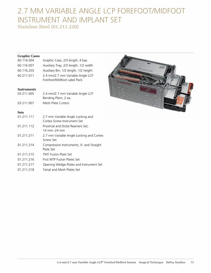
2.7 MM VARIABLE ANGLE LCP FOREFOOT/MIDFOOT INSTRUMENT AND IMPLANT SET Stainless Steel (11.211.221)
Graphic Cases 60.116.004 Graphic Case, 2/3 length, 4 bay
60.116.007 Auxiliary Tray, 2/3 length, 1/2 width
60.116.203 Auxiliary Bin, 1/2 length, 1/2 height
60.211.011 2.4 mm/2.7 mm Variable Angle LCP Forefoot/Midfoot Label Pack
Instruments 03.211.005 2.4 mm/2.7 mm Variable Angle LCP
Bending Pliers, 2 ea.
03.211.007 Mesh Plate Cutters
Sets01.211.111 2.7 mm Variable Angle Locking and
Cortex Screw Instrument Set
01.211.112 Proximal and Distal Reamers Set, 14 mm–24 mm
01.211.211 2.7 mm Variable Angle Locking and Cortex Screw Set
01.211.214 Compression Instruments, X- and Straight Plate Set
01.211.215 TMT Fusion Plate Set
01.211.216 First MTP Fusion Plates Set
01.211.217 Opening Wedge Plates and Instrument Set
01.211.218 Tarsal and Mesh Plates Set
74 DePuy Synthes 2.4 mm/2.7 mm Variable Angle LCP® Forefoot/Midfoot System Surgical Technique
2.7 MM VARIABLE ANGLE LCP FOREFOOT/MIDFOOT INSTRUMENT AND IMPLANT SET Titanium (11.211.421)
Graphic Cases 60.116.004 Graphic Case, 2/3 Length, 4 bay
60.116.007 Auxiliary Tray, 2/3 length, 1/2 width
60.116.203 Auxiliary Bin, 1/2 length, 1/2 height
60.211.011 2.4 mm/2.7 mm Variable Angle LCP Forefoot/Midfoot Label Pack
Instruments 03.211.005 2.4 mm/2.7 mm Variable Angle LCP Bending
Pliers, 2 ea.
03.211.007 Mesh Plate Cutters
Sets01.211.111 2.7 mm Variable Angle Locking and Cortex
Screw Instrument Set
01.211.112 Proximal and Distal Reamers Set, 14 mm–24 mm
01.211.411 Titanium 2.7 mm Variable Angle Locking and Cortex Screw Set
01.211.414 Titanium Compression Instruments, X- and Straight Plate Set
01.211.415 Titanium TMT Fusion Plate Set
01.211.416 Titanium First MTP Fusion Plates Set
01.211.417 Titanium Opening Wedge Plates and Instrument Set
01.211.418 Titanium Tarsal and Mesh Plates Set
2.4 mm/2.7 mm Variable Angle LCP® Forefoot/Midfoot System Surgical Technique DePuy Synthes 75
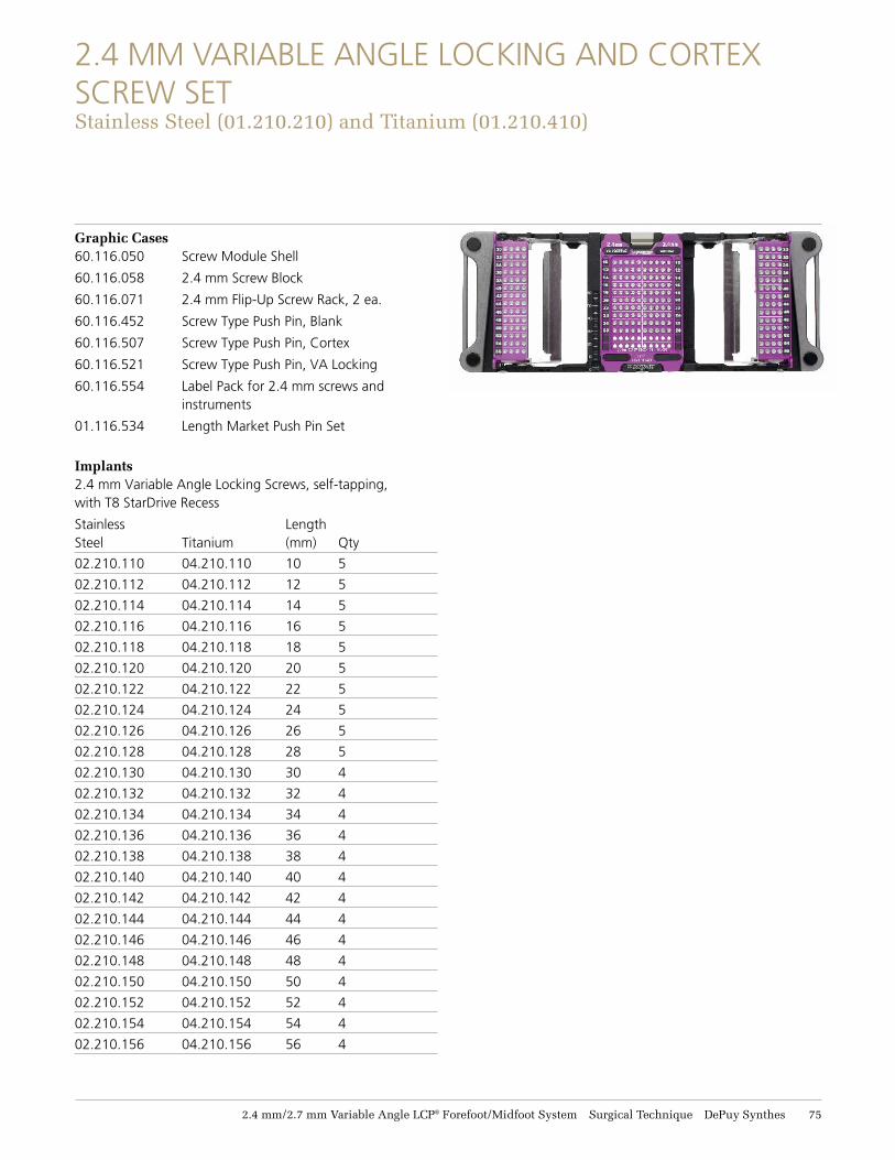
2.4 MM VARIABLE ANGLE LOCKING AND CORTEX SCREW SET Stainless Steel (11.211.211) and Titanium (11.211.411)
Graphic Cases 60.116.050 Screw Module Shell
60.116.058 2.4 mm Screw Block
60.116.071 2.4 mm Flip-Up Screw Rack, 2 ea.
60.116.452 Screw Type Push Pin, Blank
60.116.507 Screw Type Push Pin, Cortex
60.116.521 Screw Type Push Pin, VA Locking
60.116.554 Label Pack for 2.4 mm screws and instruments
01.116.534 Length Market Push Pin Set
Implants 2.4 mm Variable Angle Locking Screws, self-tapping, with T8 StarDrive Recess
Stainless Length Steel Titanium (mm) Qty
02.210.110 04.210.110 10 5
02.210.112 04.210.112 12 5
02.210.114 04.210.114 14 5
02.210.116 04.210.116 16 5
02.210.118 04.210.118 18 5
02.210.120 04.210.120 20 5
02.210.122 04.210.122 22 5
02.210.124 04.210.124 24 5
02.210.126 04.210.126 26 5
02.210.128 04.210.128 28 5
02.210.130 04.210.130 30 4
02.210.132 04.210.132 32 4
02.210.134 04.210.134 34 4
02.210.136 04.210.136 36 4
02.210.138 04.210.138 38 4
02.210.140 04.210.140 40 4
02.210.142 04.210.142 42 4
02.210.144 04.210.144 44 4
02.210.146 04.210.146 46 4
02.210.148 04.210.148 48 4
02.210.150 04.210.150 50 4
02.210.152 04.210.152 52 4
02.210.154 04.210.154 54 4
02.210.156 04.210.156 56 4
76 DePuy Synthes 2.4 mm/2.7 mm Variable Angle LCP® Forefoot/Midfoot System Surgical Technique
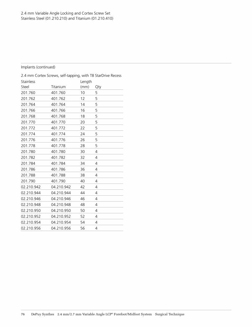
2.4 mm Variable Angle Locking and Cortex Screw Set Stainless Steel (01.210.210) and Titanium (01.210.410)
Implants (continued)
2.4 mm Cortex Screws, self-tapping, with T8 StarDrive Recess
Stainless Length Steel Titanium (mm) Qty
201.760 401.760 10 5
201.762 401.762 12 5
201.764 401.764 14 5
201.766 401.766 16 5
201.768 401.768 18 5
201.770 401.770 20 5
201.772 401.772 22 5
201.774 401.774 24 5
201.776 401.776 26 5
201.778 401.778 28 5
201.780 401.780 30 4
201.782 401.782 32 4
201.784 401.784 34 4
201.786 401.786 36 4
201.788 401.788 38 4
201.790 401.790 40 4
02.210.942 04.210.942 42 4
02.210.944 04.210.944 44 4
02.210.946 04.210.946 46 4
02.210.948 04.210.948 48 4
02.210.950 04.210.950 50 4
02.210.952 04.210.952 52 4
02.210.954 04.210.954 54 4
02.210.956 04.210.956 56 4
2.4 mm/2.7 mm Variable Angle LCP® Forefoot/Midfoot System Surgical Technique DePuy Synthes 77
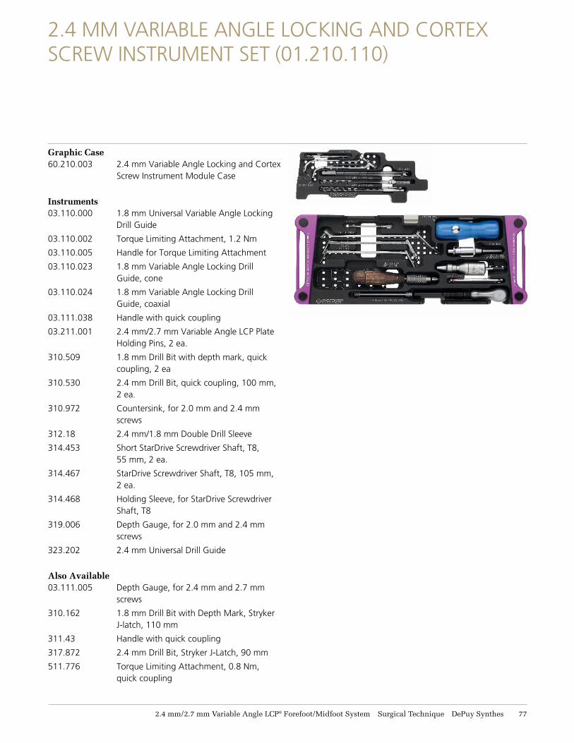
2.4 MM VARIABLE ANGLE LOCKING AND CORTEX SCREW INSTRUMENT SET (01.210.110)
Graphic Case 60.210.003 2.4 mm Variable Angle Locking and Cortex
Screw Instrument Module Case
Instruments 03.110.000 1.8 mm Universal Variable Angle Locking
Drill Guide
03.110.002 Torque Limiting Attachment, 1.2 Nm
03.110.005 Handle for Torque Limiting Attachment
03.110.023 1.8 mm Variable Angle Locking Drill Guide, cone
03.110.024 1.8 mm Variable Angle Locking Drill Guide, coaxial
03.111.038 Handle with quick coupling
03.211.001 2.4 mm/2.7 mm Variable Angle LCP Plate Holding Pins, 2 ea.
310.509 1.8 mm Drill Bit with depth mark, quick coupling, 2 ea
310.530 2.4 mm Drill Bit, quick coupling, 100 mm, 2 ea.
310.972 Countersink, for 2.0 mm and 2.4 mm screws
312.18 2.4 mm/1.8 mm Double Drill Sleeve
314.453 Short StarDrive Screwdriver Shaft, T8, 55 mm, 2 ea.
314.467 StarDrive Screwdriver Shaft, T8, 105 mm, 2 ea.
314.468 Holding Sleeve, for StarDrive Screwdriver Shaft, T8
319.006 Depth Gauge, for 2.0 mm and 2.4 mm screws
323.202 2.4 mm Universal Drill Guide
Also Available 03.111.005 Depth Gauge, for 2.4 mm and 2.7 mm
screws
310.162 1.8 mm Drill Bit with Depth Mark, Stryker J-latch, 110 mm
311.43 Handle with quick coupling
317.872 2.4 mm Drill Bit, Stryker J-Latch, 90 mm
511.776 Torque Limiting Attachment, 0.8 Nm, quick coupling
78 DePuy Synthes 2.4 mm/2.7 mm Variable Angle LCP® Forefoot/Midfoot System Surgical Technique
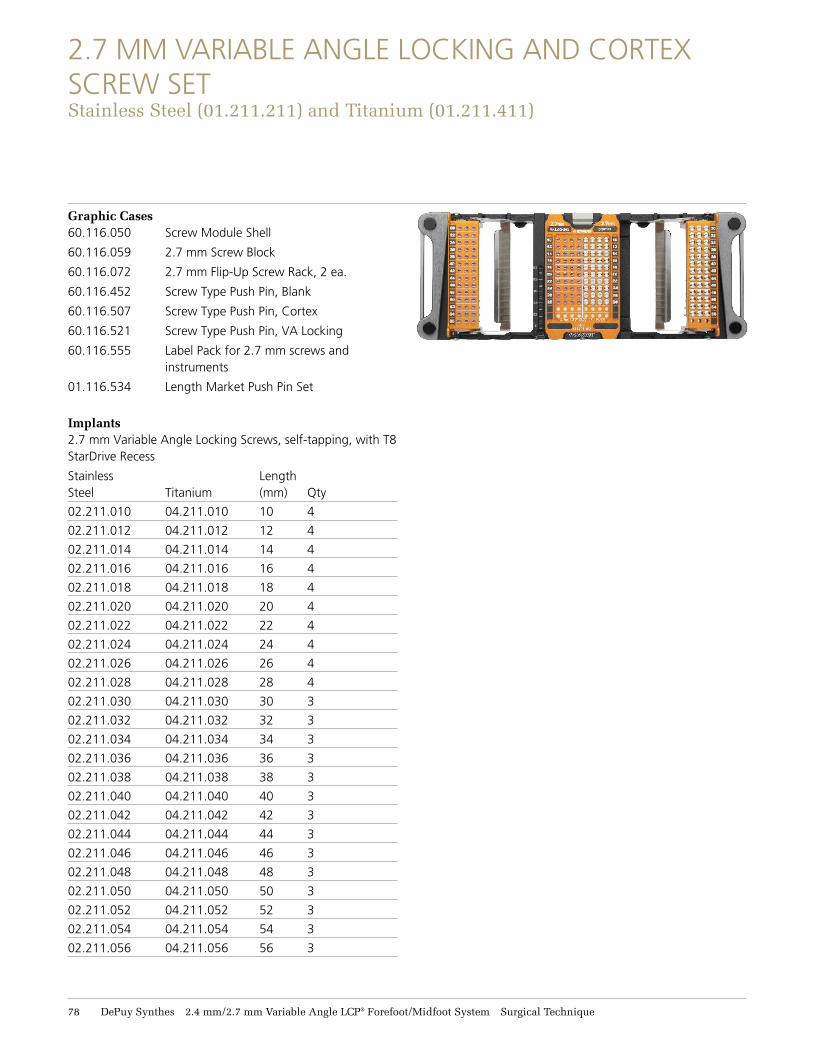
2.7 MM VARIABLE ANGLE LOCKING AND CORTEX SCREW SET Stainless Steel (11.211.211) and Titanium (11.211.411)
Graphic Cases 60.116.050 Screw Module Shell
60.116.059 2.7 mm Screw Block
60.116.072 2.7 mm Flip-Up Screw Rack, 2 ea.
60.116.452 Screw Type Push Pin, Blank
60.116.507 Screw Type Push Pin, Cortex
60.116.521 Screw Type Push Pin, VA Locking
60.116.555 Label Pack for 2.7 mm screws and instruments
01.116.534 Length Market Push Pin Set
Implants 2.7 mm Variable Angle Locking Screws, self-tapping, with T8 StarDrive Recess
Stainless Length Steel Titanium (mm) Qty
02.211.010 04.211.010 10 4
02.211.012 04.211.012 12 4
02.211.014 04.211.014 14 4
02.211.016 04.211.016 16 4
02.211.018 04.211.018 18 4
02.211.020 04.211.020 20 4
02.211.022 04.211.022 22 4
02.211.024 04.211.024 24 4
02.211.026 04.211.026 26 4
02.211.028 04.211.028 28 4
02.211.030 04.211.030 30 3
02.211.032 04.211.032 32 3
02.211.034 04.211.034 34 3
02.211.036 04.211.036 36 3
02.211.038 04.211.038 38 3
02.211.040 04.211.040 40 3
02.211.042 04.211.042 42 3
02.211.044 04.211.044 44 3
02.211.046 04.211.046 46 3
02.211.048 04.211.048 48 3
02.211.050 04.211.050 50 3
02.211.052 04.211.052 52 3
02.211.054 04.211.054 54 3
02.211.056 04.211.056 56 3
2.4 mm/2.7 mm Variable Angle LCP® Forefoot/Midfoot System Surgical Technique DePuy Synthes 79
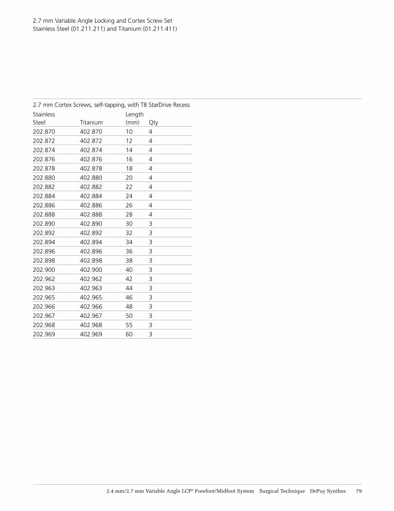
2.7 mm Variable Angle Locking and Cortex Screw Set Stainless Steel (01.211.211) and Titanium (01.211.411)
2.7 mm Cortex Screws, self-tapping, with T8 StarDrive Recess
Stainless Length Steel Titanium (mm) Qty
202.870 402.870 10 4
202.872 402.872 12 4
202.874 402.874 14 4
202.876 402.876 16 4
202.878 402.878 18 4
202.880 402.880 20 4
202.882 402.882 22 4
202.884 402.884 24 4
202.886 402.886 26 4
202.888 402.888 28 4
202.890 402.890 30 3
202.892 402.892 32 3
202.894 402.894 34 3
202.896 402.896 36 3
202.898 402.898 38 3
202.900 402.900 40 3
202.962 402.962 42 3
202.963 402.963 44 3
202.965 402.965 46 3
202.966 402.966 48 3
202.967 402.967 50 3
202.968 402.968 55 3
202.969 402.969 60 3
81 DePuy Synthes 2.4 mm/2.7 mm Variable Angle LCP® Forefoot/Midfoot System Surgical Technique
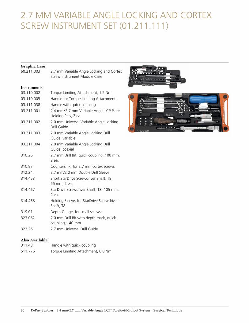
2.7 MM VARIABLE ANGLE LOCKING AND CORTEX SCREW INSTRUMENT SET (01.211.111)
Graphic Case 60.211.003 2.7 mm Variable Angle Locking and Cortex
Screw Instrument Module Case
Instruments 03.110.002 Torque Limiting Attachment, 1.2 Nm
03.110.005 Handle for Torque Limiting Attachment
03.111.038 Handle with quick coupling
03.211.001 2.4 mm/2.7 mm Variable Angle LCP Plate Holding Pins, 2 ea.
03.211.002 2.0 mm Universal Variable Angle Locking Drill Guide
03.211.003 2.0 mm Variable Angle Locking Drill Guide, variable
03.211.004 2.0 mm Variable Angle Locking Drill Guide, coaxial
310.26 2.7 mm Drill Bit, quick coupling, 100 mm, 2 ea.
310.87 Countersink, for 2.7 mm cortex screws
312.24 2.7 mm/2.0 mm Double Drill Sleeve
314.453 Short StarDrive Screwdriver Shaft, T8, 55 mm, 2 ea.
314.467 StarDrive Screwdriver Shaft, T8, 105 mm, 2 ea.
314.468 Holding Sleeve, for StarDrive Screwdriver Shaft, T8
319.01 Depth Gauge, for small screws
323.062 2.0 mm Drill Bit with depth mark, quick coupling, 140 mm
323.26 2.7 mm Universal Drill Guide
Also Available 311.43 Handle with quick coupling
511.776 Torque Limiting Attachment, 0.8 Nm
2.4 mm/2.7 mm Variable Angle LCP® Forefoot/Midfoot System Surgical Technique DePuy Synthes 81
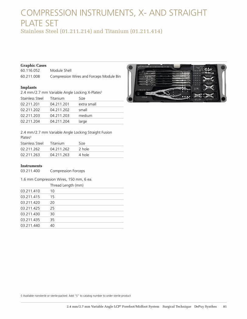
COMPRESSION INSTRUMENTS, X- AND STRAIGHT PLATE SET Stainless Steel (11.211.214) and Titanium (11.211.414)
Graphic Cases60.116.052 Module Shell
60.211.008 Compression Wires and Forceps Module Bin
Implants2.4 mm/2.7 mm Variable Angle Locking X-Plates◊
Stainless Steel Titanium Size
02.211.201 04.211.201 extra small
02.211.202 04.211.202 small
02.211.203 04.211.203 medium
02.211.204 04.211.204 large
2.4 mm/2.7 mm Variable Angle Locking Straight Fusion Plates◊
Stainless Steel Titanium Size
02.211.262 04.211.262 2 hole
02.211.263 04.211.263 4 hole
Instruments 03.211.400 Compression Forceps
1.6 mm Compression Wires, 150 mm, 6 ea.
Thread Length (mm)
03.211.410 10
03.211.415 15
03.211.420 20
03.211.425 25
03.211.430 30
03.211.435 35
03.211.440 40
◊ Available nonsterile or sterile-packed. Add “S” to catalog number to order sterile product
82 DePuy Synthes 2.4 mm/2.7 mm Variable Angle LCP® Forefoot/Midfoot System Surgical Technique
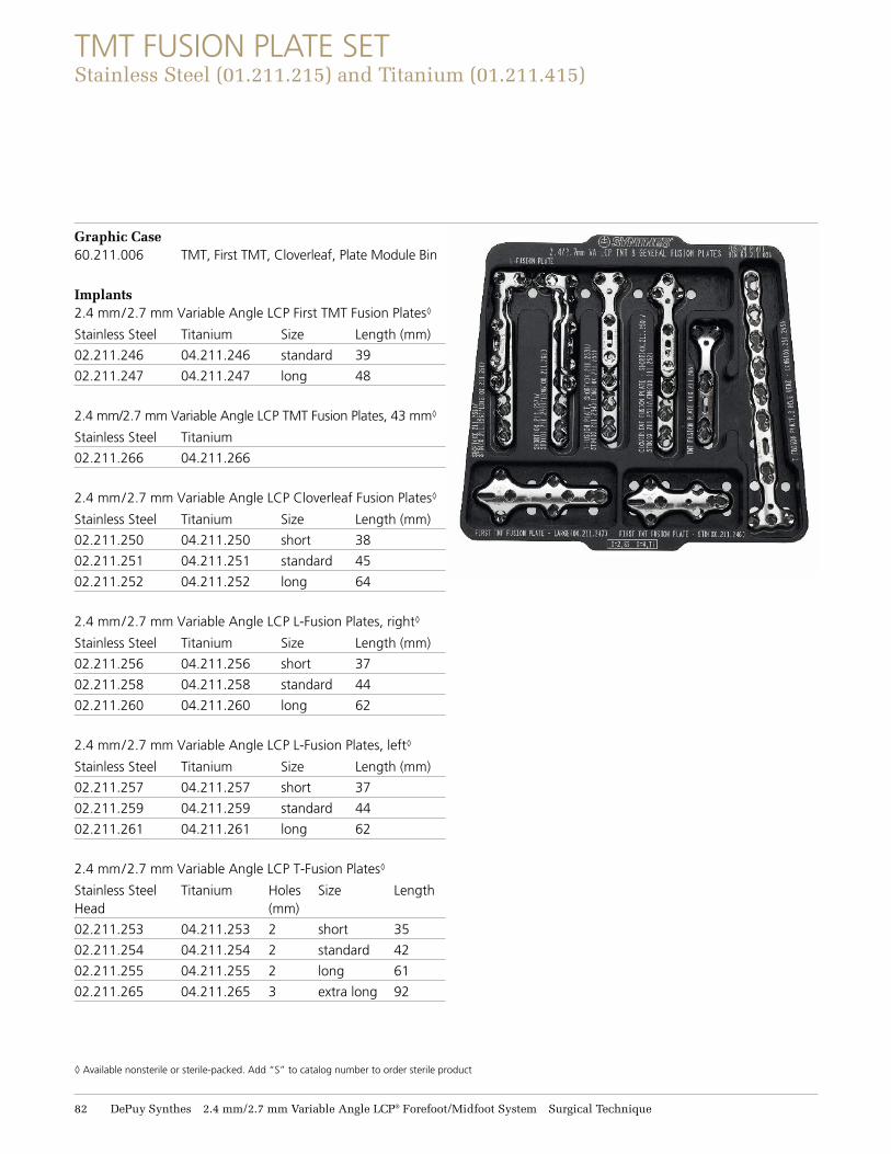
TMT FUSION PLATE SET Stainless Steel (11.211.215) and Titanium (11.211.415)
Graphic Case 60.211.006 TMT, First TMT, Cloverleaf, Plate Module Bin
Implants2.4 mm/2.7 mm Variable Angle LCP First TMT Fusion Plates◊
Stainless Steel Titanium Size Length (mm)
02.211.246 04.211.246 standard 39
02.211.247 04.211.247 long 48
2.4 mm/2.7 mm Variable Angle LCP TMT Fusion Plates, 43 mm◊
Stainless Steel Titanium
02.211.266 04.211.266
2.4 mm/2.7 mm Variable Angle LCP Cloverleaf Fusion Plates◊
Stainless Steel Titanium Size Length (mm)
02.211.250 04.211.250 short 38
02.211.251 04.211.251 standard 45
02.211.252 04.211.252 long 64
2.4 mm/2.7 mm Variable Angle LCP L-Fusion Plates, right◊
Stainless Steel Titanium Size Length (mm)
02.211.256 04.211.256 short 37
02.211.258 04.211.258 standard 44
02.211.260 04.211.260 long 62
2.4 mm/2.7 mm Variable Angle LCP L-Fusion Plates, left◊
Stainless Steel Titanium Size Length (mm)
02.211.257 04.211.257 short 37
02.211.259 04.211.259 standard 44
02.211.261 04.211.261 long 62
2.4 mm/2.7 mm Variable Angle LCP T-Fusion Plates◊
Stainless Steel Titanium Holes Size Length Head (mm)
02.211.253 04.211.253 2 short 35
02.211.254 04.211.254 2 standard 42
02.211.255 04.211.255 2 long 61
02.211.265 04.211.265 3 extra long 92
◊ Available nonsterile or sterile-packed. Add “S” to catalog number to order sterile product
2.4 mm/2.7 mm Variable Angle LCP® Forefoot/Midfoot System Surgical Technique DePuy Synthes 83
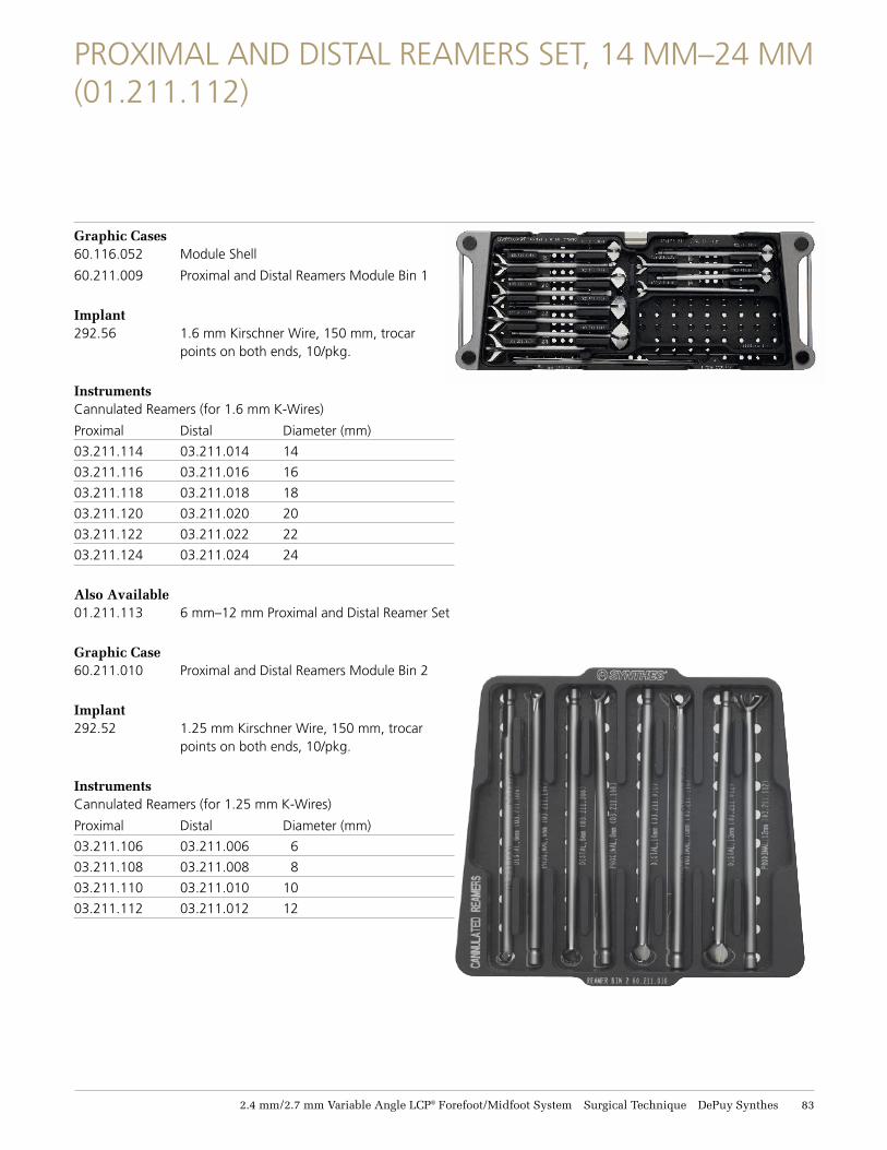
PROXIMAL AND DISTAL REAMERS SET, 14 MM–24 MM (01.211.112)
Graphic Cases 60.116.052 Module Shell
60.211.009 Proximal and Distal Reamers Module Bin 1
Implant 292.56 1.6 mm Kirschner Wire, 150 mm, trocar
points on both ends, 10/pkg.
Instruments Cannulated Reamers (for 1.6 mm K-Wires)
Proximal Distal Diameter (mm)
03.211.114 03.211.014 14
03.211.116 03.211.016 16
03.211.118 03.211.018 18
03.211.120 03.211.020 20
03.211.122 03.211.022 22
03.211.124 03.211.024 24
Also Available 01.211.113 6 mm–12 mm Proximal and Distal Reamer Set
Graphic Case 60.211.010 Proximal and Distal Reamers Module Bin 2
Implant 292.52 1.25 mm Kirschner Wire, 150 mm, trocar
points on both ends, 10/pkg.
Instruments Cannulated Reamers (for 1.25 mm K-Wires)
Proximal Distal Diameter (mm)
03.211.106 03.211.006 6
03.211.108 03.211.008 8
03.211.110 03.211.010 10
03.211.112 03.211.012 12
84 DePuy Synthes 2.4 mm/2.7 mm Variable Angle LCP® Forefoot/Midfoot System Surgical Technique
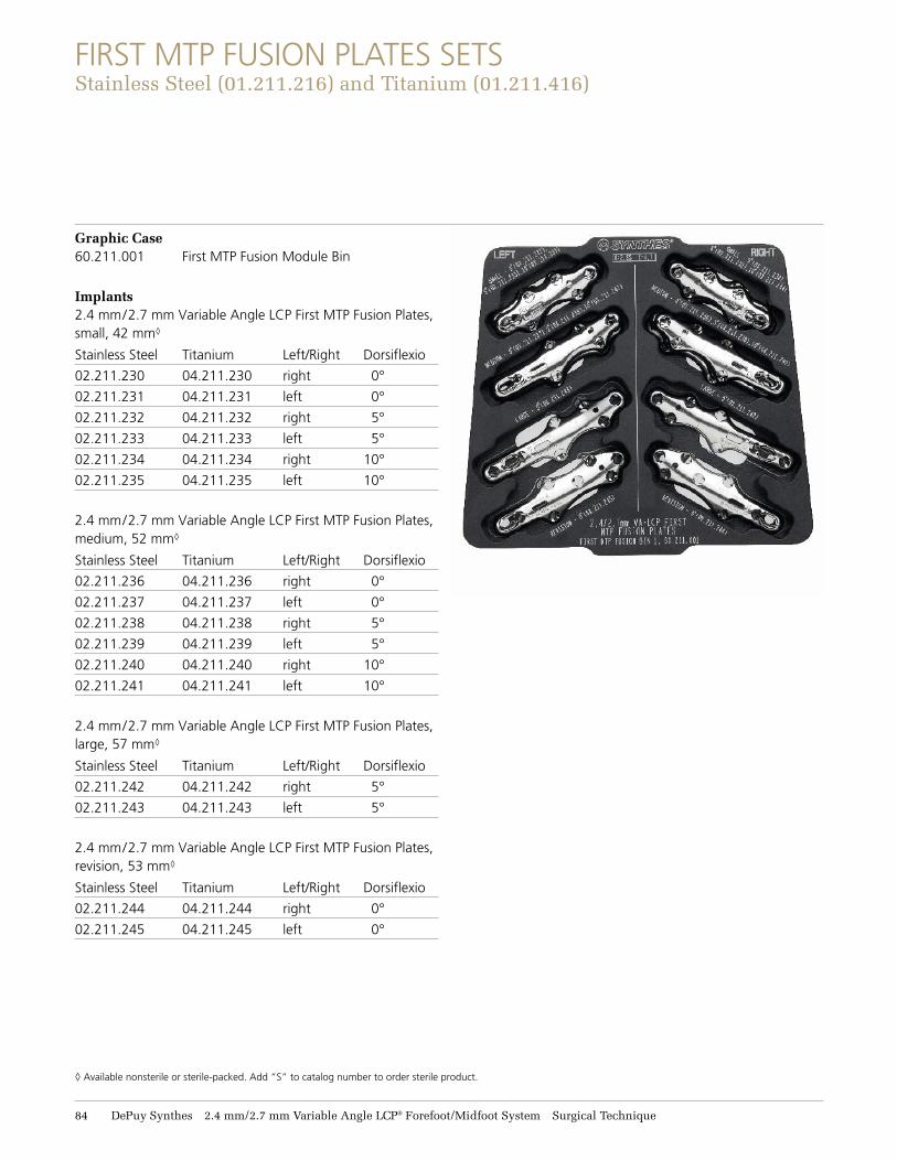
FIRST MTP FUSION PLATES SETS Stainless Steel (11.211.216) and Titanium (11.211.416)
Graphic Case 60.211.001 First MTP Fusion Module Bin
Implants 2.4 mm/2.7 mm Variable Angle LCP First MTP Fusion Plates, small, 42 mm◊
Stainless Steel Titanium Left/Right Dorsiflexio
02.211.230 04.211.230 right 0°
02.211.231 04.211.231 left 0°
02.211.232 04.211.232 right 5°
02.211.233 04.211.233 left 5°
02.211.234 04.211.234 right 10°
02.211.235 04.211.235 left 10°
2.4 mm/2.7 mm Variable Angle LCP First MTP Fusion Plates, medium, 52 mm◊
Stainless Steel Titanium Left/Right Dorsiflexio
02.211.236 04.211.236 right 0°
02.211.237 04.211.237 left 0°
02.211.238 04.211.238 right 5°
02.211.239 04.211.239 left 5°
02.211.240 04.211.240 right 10°
02.211.241 04.211.241 left 10°
2.4 mm/2.7 mm Variable Angle LCP First MTP Fusion Plates, large, 57 mm◊
Stainless Steel Titanium Left/Right Dorsiflexio
02.211.242 04.211.242 right 5°
02.211.243 04.211.243 left 5°
2.4 mm/2.7 mm Variable Angle LCP First MTP Fusion Plates, revision, 53 mm◊
Stainless Steel Titanium Left/Right Dorsiflexio
02.211.244 04.211.244 right 0°
02.211.245 04.211.245 left 0°
◊ Available nonsterile or sterile-packed. Add “S” to catalog number to order sterile product.
2.4 mm/2.7 mm Variable Angle LCP® Forefoot/Midfoot System Surgical Technique DePuy Synthes 85
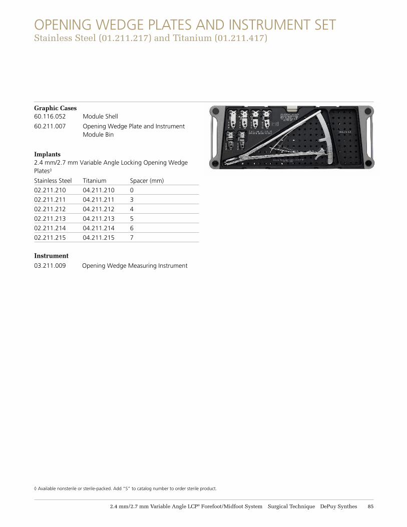
OPENING WEDGE PLATES AND INSTRUMENT SET Stainless Steel (11.211.217) and Titanium (11.211.417)
Graphic Cases 60.116.052 Module Shell
60.211.007 Opening Wedge Plate and Instrument Module Bin
Implants 2.4 mm/2.7 mm Variable Angle Locking Opening Wedge Plates◊
Stainless Steel Titanium Spacer (mm)
02.211.210 04.211.210 0
02.211.211 04.211.211 3
02.211.212 04.211.212 4
02.211.213 04.211.213 5
02.211.214 04.211.214 6
02.211.215 04.211.215 7
Instrument03.211.009 Opening Wedge Measuring Instrument
◊ Available nonsterile or sterile-packed. Add “S” to catalog number to order sterile product.
86 DePuy Synthes 2.4 mm/2.7 mm Variable Angle LCP® Forefoot/Midfoot System Surgical Technique
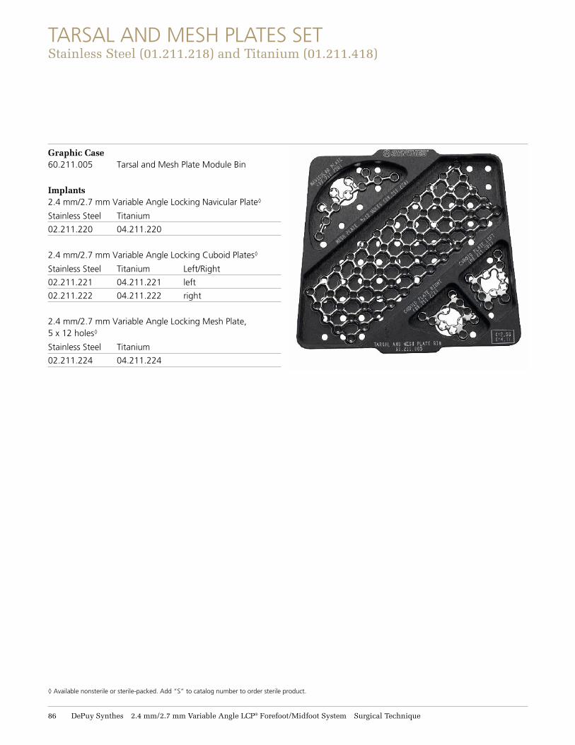
TARSAL AND MESH PLATES SET Stainless Steel (11.211.218) and Titanium (11.211.418)
Graphic Case 60.211.005 Tarsal and Mesh Plate Module Bin
Implants2.4 mm/2.7 mm Variable Angle Locking Navicular Plate◊
Stainless Steel Titanium
02.211.220 04.211.220
2.4 mm/2.7 mm Variable Angle Locking Cuboid Plates◊
Stainless Steel Titanium Left/Right
02.211.221 04.211.221 left
02.211.222 04.211.222 right
2.4 mm/2.7 mm Variable Angle Locking Mesh Plate, 5 x 12 holes◊
Stainless Steel Titanium
02.211.224 04.211.224
◊ Available nonsterile or sterile-packed. Add “S” to catalog number to order sterile product.
© DePuy Synthes 2010–2021. All rights reserved. DSUS/TRM/0916/1043 Rev B 05/21 DV
Synthes USA, LLC 1101 Synthes AvenueMonument, CO 80132
Manufactured or distributed by:Synthes USA Products, LLC 1302 Wrights Lane EastWest Chester, PA 19380
To order (USA): 800-523-0322 To order (Canada): 844-243-4321
Note: For recognized manufacturer, refer to the product label.
www.depuysynthes.com
Limited Warranty and Disclaimer: DePuy Synthes products are sold with a limited warranty to the original purchaser against defects in workmanship
and materials. Any other express or implied warranties, including warranties of merchantability or fitness, are hereby disclaimed.
Please also refer to the package insert(s) or other labeling associated with the devices identified in this surgical technique for additional information.
CAUTION: Federal Law restricts these devices to sale by or on the order of a physician.
Some devices listed in this technique guide may not have been licensed in accordance with Canadian law and may not be for sale in Canada. Please
contact your sales consultant for items approved for sale in Canada.
Not all products may currently be available in all markets.
Synthes GmbHLuzernstrasse 214528 Zuchwil, Switzerland