Procedure for SitS Performance Calculations
14
SSCL-N-869 SSC Cryo Note No. 93-17 Procedure for SitS Performance Calculations J. Demko and V. Ganni Superconducting Super Collider Laboratory* 2550 Beckleymeade Ave. Dallas, TX 75237 July 1994 tperated by the Universities Research Association, Inc., for the U.S. Department of Energy under Contract No. DE-AC35-89ER40486.
Transcript of Procedure for SitS Performance Calculations
SSCL-N-869SSCCryo Note No. 93-17
Procedure for SitS PerformanceCalculations
J. Demko andV. Ganni
Superconducting Super Collider Laboratory*2550BeckleymeadeAve.
Dallas, TX 75237
July 1994
tperatedby the UniversitiesResearchAssociation, Inc., for the U.S. Department of Energy under ContractNo. DE-AC35-89ER40486.

SSCCryo Note 93-17
PROCEDURE FOR
SRS
PERFORMANCE CALCULATIONS
J. Deniko and V. Ganni
THE SUPERCONDUCTINGSUPERCOLLIDER LABORATORY
ASD/CRYOGENICS
May 1993

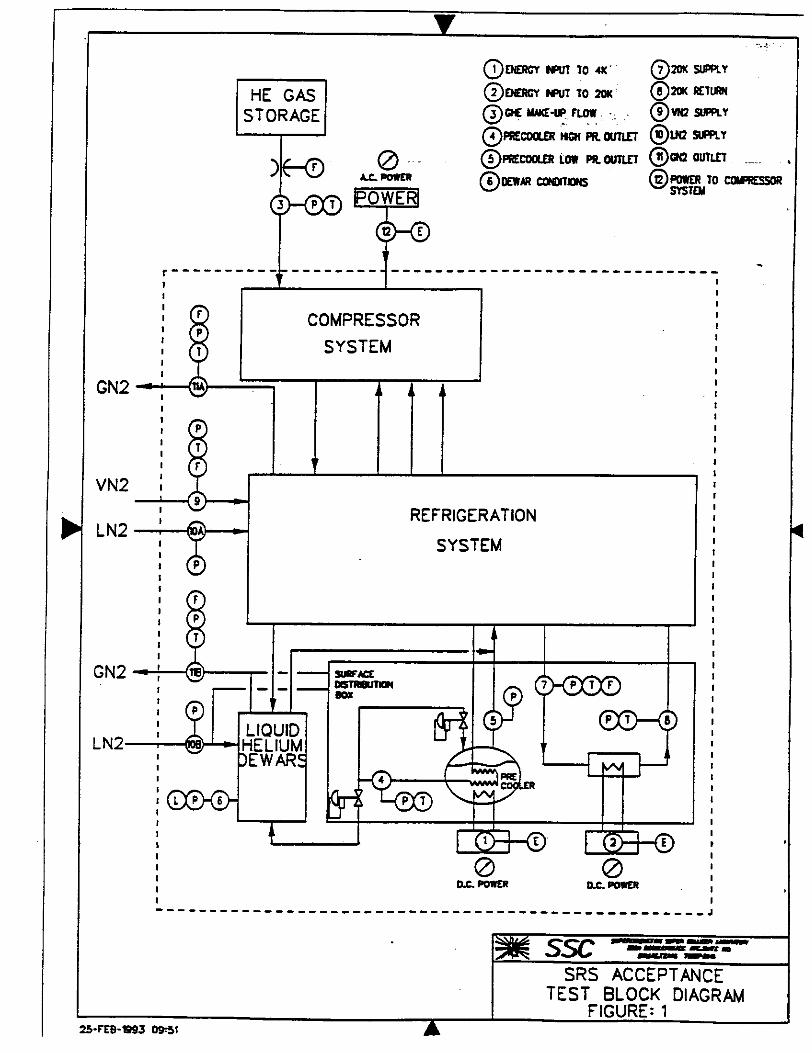
IntroductionAcceptancetestingof theSectorRefrigeratorSurfaceSystemSRSwill be performedas
describedin section3.9of the SRSTechnicalSpecification[1]. The SRSacceptancetestblockdiagramis shownin Figure1. It depictsthesystemcapacityfor the4 K and20K loads,theequivalentinput powerto thesystem,andthelocationsandparametermeasurementsnecessarytoverify theperformanceof theSRS.
The 4 K and20 K acceptancetestrefrigerationloadsandtheliquefactionloadsrequiredby thedesignmodeacceptancetestand thevarious streaminlet andoutletconditionsaxeprovidedinTable 1. Theheatleaksto anypart of the systeme.g.,coldbox,surfacedistributionbox,dewars,transferlinesarenot part of therequiredcapacityand cannotbe includedin determiningthecapacityoroverall efficiencyof thesystemasspecified[11.
The 4 K and 20 K acceptancetest loadsareapplied andmeasuredby theelectricalheatinputin thesurfacedistributionbox. The refrigerationloadsshownin Table I will be appliedto heatersin the4 K precoolerand to the20K loop. The liquefactionratewill be measuredby observingtheroomtemperaturemakeupgasflow andwill be verifiedby therateof accumulationof liquid in thedewar.Thesetwo valuesshoulddiffer only by thedisplacedvapormassflow from thedewar.TheSRSacceptancetestsrequirea demonstratedminimumdesigncapacityandoverall efficiency asdefinedin [1]. The procedurefor determiningthesystemoverall efficiencyandcapacityfrommeasurementsis discussedbelow.
UncertaintyCalculationTheoryThe calculateduncertaintiesfor themeasurementof asectorrefrigerationstationSRSCarnot
powerandoverall efficiency can be determinedfrom themeasuredquantitiesshownin Figure 1.The uncertaintycalculationsweremadeusingtheequation1 from Holman[2], whichis thesameastheprecisionindexof a resultasdefinedin Section3 of ANSUASME PTC19.1 [3]. In thisequationV representsthedependentvariable,5V theuncertaintyof V, the;‘s aretheindependentvariablesand the&‘s arethe uncertaintiesin the measurementsof theindependentvariables.Ithasbeenassumedthat thebias in themeasurementsis negligible. The dependentvariablesofinterestarethesystemdeliverableCarnotcapacityandtheoverall efficiencygiven by equations2 and3.
SV= jz 18Xi
I
= + Pjjq + reliq ÷ 2OK2
P03
act
1
I.C. POWER
PPUT 10 41C
isil 10 20K
&wcE-w FL.
Sw PtflET
caalms
®20k SUPPLY
®20K
®L112 SUPPLY
oUIzZt
POWER TO COIPtSSORSYSTEM
REFRIGERATION
SYSTEM
o 0D.C. POWER D.C. POWER
ssc -a-gaaws -
SRSTEST
ACCEPTANCEBLOCK DIAGRAM
FIGURE: 125-FEB-93 09,51
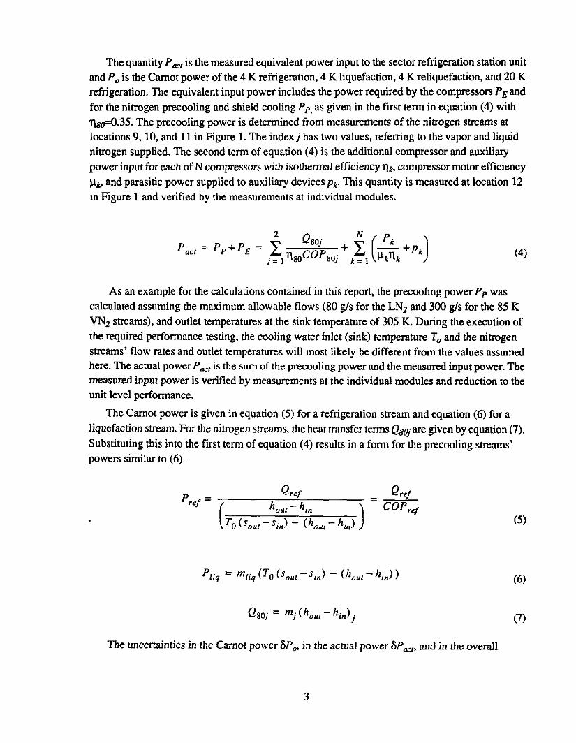
The quantityP is themeasuredequivalentpowerinputto thesectorrefrigerationstationunitandP0 is theCarnotpowerof the4 K refrigeration,4 K liquefaction,4 K reliquefaction,and20 Krefrigeration.The equivalentinput powerincludesthepowerrequiredby thecompressorsE andfor thenitrogenprecoolingand shieldcoolingJ’ asgiven in thefirst termin equation4 with
1180=0.35. The precoolingpoweris determinedfrom measurementsof thenitrogenstreamsatlocations9, 10, and 11 in Figure 1. The index] has two values,referringto thevapor andliquidnitrogensupplied.The secondtermofequation4 is theadditionalcompressorand auxiliarypowerinputfor eachof N compressorswith isothermalefficiencyThu compressormotorefficiency
11k. andparasiticpowersuppliedto auxiliary devicesPk This quantityis measuredat location12in Figure 1 and verifiedby themeasurementsat individual modules.
tact = += + k=I
+ PkJ 4
As an examplefor thecalculationscontainedin this report, theprecoolingpowerPp wascalculatedassumingthe maximumallowableflows 80 g/s for theLN2 and300 g/s for the85 KVN2 streams,and outlettemperaturesat thesink temperatureof 305 K. During theexecutionofthe requiredperformancetesting,thecooling waterinlet sink temperatureT0 and thenitrogenstreams’flow ratesand outlettemperatureswill mostlikely be different from thevaluesassumedhere.The actualpowerP is thesumoftheprecoolingpowerandthemeasuredinputpower.Themeasuredinputpoweris verified by measurementsat theindividual modulesandreductionto theunit level performance.
The Camotpoweris given in equation5 for a refrigerationstreamand equation6 for aliquefactionstream.For thenitrogenstreams,theheattransfertermsQ801aregivenby equation7.Substitutingthis into thefirst termof equation4 resultsin a form for theprecoolingstreams’powerssimilar to 6.
- Qref Qre1ref
-
- -
_______
T0 - s1 - h0 - h14 5
"Iiq = mjjq T0 s0, - s1 - h01 - 6
= 7
The uncertaintiesin theCarnorpower8P, in theactualpower8P,, and in theoverall
3
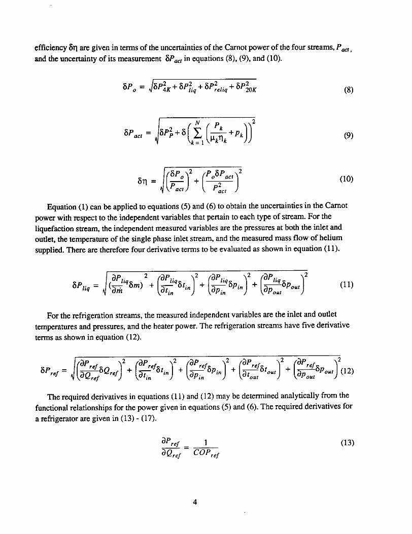
efficiency611 aregivenin termsof theuncertaintiesof theCarnotpowerof thefour streams,Pandthe uncertaintyof its measurement6P in equations8, 9, and10.
oP0 = + OP?iq + 8Pjjq + OPOK 8
= jOP + 6 L1 k+Pk 9
2 2
= iH +
10
Equation1 can be appliedto equations5 and6 to obtaintheuncertaintiesin theCarnotpowerwith respectto theindependentvariablesthat pertain to eachtype of stream.For theliquefaction stream,theindependentmeasuredvariablesare thepressuresat both theinlet andoutlet,thetemperatureof thesinglephaseinlet stream,andthemeasuredmassflow of heliumsupplied.Therearethereforefour derivativetermsto be evaluatedas shownin equation11.
2 ,- 2 a 2 f
6iiq = J_Y"6m + __6tinJ + + 11in in Pour
For therefrigerationstreams,themeasuredindependentvariablesaretheinlet andoutlettemperaturesandpressures,andtheheaterpower.The refrigerationstreamshavefive derivativetermsasshownin equation12.
OPre1 =ic:oQre42 + + + +
Therequiredderivativesin equations11 and12 may be determinedanalyticallyfrom thefunctionalrelationshipsfor thepowergiven in equations5 and6. The requiredderivativesfora refrigeratoraregiven in 13 - 17.
°ref - 1 13&Qrei - COPref
4

at’ref s0, - sin ah,, 1= Qrefi’ø
h01- hin2T - h0, - hin 1i 14
apref s0 - sin ah1 1 asl?,= QreiTo / - h 2 - h - h. 15
aPref s0 - s, ah0= QrefTO
h0 - h1 aç, - h01 - hi,, 2at,2 16
aPrei-
a50, - ah0,
_____
- QrefTo h01 - hin &01- h0 - h1 2ap 17
The appropriatederivativesfor a liquefier aregiven by equations18 - 21. The nitrogenstreamscontainoneadditionalderivativetermgiven by 22. The propertyderivativescontainedin theseexpressionswereevaluatedapproximatelyby finite differences.
at’,.
___
IL. I.am - 10 ‘3ou: - 5in - k"out - "in 18liq
&Pjjq ds= mjjq-To--+.-j 19
aP,jq E1s= m,jq-To.-+-- 20
aP,jq ah0,
_____
= m,jq 7’oap- ap01 21
_____
ah0,= mliq Toat
- ac1 22
Test ConsiderationsAll of the test runsbegin whensteadystateis reached.Soafteran operatingmodechangein
theheliumrefrigerator/liquefierthe systemshouldbe allowedto run for a sufficienttime to allow
5

the systemto reachequilibrium beforebeginninga performancetest.
Thedesignmodetestrun is to be usedto determinetheoverall efficiency incentive.The testdurationis 48 hours,soaperformancedatapoint shouldbe determinedfor everyhalf hourproviding96 setsof performancedatapoints. For the nominalmode,thetestdurationis only 24hoursso performancedatashouldbe determinedevery 15 minutesto providethesamenumberofperformancedatasets.Theactualmeasureddataquantitiesi. e.,pressures,temperatures,flow, andpowerusedto determinetheoverall efficiency andcapacitieswill be readata higherrateof onesetofdataevery 1-5 minutes.Themeasurementswill then be averagedand theaverageusedtodeterminetheoverall efficiency andcapacitiesfor that 30 minute or 15 minute interval. Thevaluesof overall efficiencyand capacitiesdeterminedfor all of the30 minuteor 15 minuteintervalswill be usedto determinethemeanoverall efficiency andmeancapacitiesfor theSRS.
Theuncertaintyof thesemeasurementshasbeendiscussedpreviouslyin this Cryo Noteinorderto providea measureof theaccuracyof a particularmeasurement.Associatedwith thesetofmeasurementswill be somedistribution similar to that shownin Figure 2 assumingthat theerrorsarerandom.Someofthescatterin thedatawill bedueto changesin ambientconditionswhich mayeffectthesystemoperationandcalculationof theoverall efficiency.The95% confidencelevelmeansthat thereis a95% chancethat thetrue valueis containedbetweenV,,,20± 2a.If a normaldistributionis followed, asshownin thefigure, the meanvaluewill also be themostfrequentlyoccurring,and oughtto be usedfor determiningcompliancewith the Specificationandfordeterminingtheincentives.
U
Ct
Measuredoverall efficiency q,1or CamotcapacitiesP0
Figure 2: Distributionof measuredparametersshowing95% confidencelevel limits of 2cy
Thetreatmentof outliersshould be handledasdescribedin ANSI/ASME PTC 19.1- 1985 orlater. It shouldbe appliedfirst to the measureddatausedto determinetheoverall efficiency andcapacitiesfor a particulartime, andsecondin thedeterminationof themeanoverall efficiencyand
Measured Mean Value
Vnwan + 2aVmean 2n
6

capacities.Thestandardrecommendsthe useof theThompson‘c TechniqueModified. In this
techniquethedeviationof eachsuspectedmeasurementfrom theaveragevalued = xrx5 is
comparedwith t times thestandarddeviationa. If thedeviationis greaterthanthis quantity
i.e., d1 > ‘ca, thenthepoint is consideredspuriousandis deletedfrom thedataset;theaverageand
standarddeviationarethenrecomputed.Thestandardrecommendsreapplyingthetechniqueuntil
thereareno outliersremaining.Thevalueoft dependson the samplesize.A tablecontainedin the
standard[31 providesa valueof t = 1.924for a samplesizeof 40.For the96 datapointsto be taken
in theseperformancetests,r may beassumedto be 1.970basedon alinearextrapolationofvalues
from thetablein [3].
Themeanvaluesobtainedaftercornpleting thisprocesswill be comparedto theguarantees
proposedbythe vendorstheyshall begreaterthan theminimumrequiredin 1 to determine
theefficiencyandcapacitycredits.
ResultsandDiscussionThe accuracyof themeasurementsmustbe known in orderto calculatetheuncertaintiesgiven
by theseequations.For onesetof thecalculationstheaccuraciesweretakenfrom theSRStechnicalspecification [11. Two additional caseswere calculatedwherea lower andhigheraccuracyofcertainmeasuredinputs wasassumed.Theaccuracyvaluesusedin this analysisaresummarized
in Table2.
Table3 containsthecalculateduncertaintiesof theCarnotpowerrequiredby the4K and20 Krefrigerationstreamsandfor the4 K liquefactionand reliquefactionstreams.Therefrigeration,
liquefaction,andreliquefactionstreamsarealso brokendowninto theuncertaintydueto theheatloadormassflow uncertaintyandtheuncertaintyin themeasurementof COP,which is determinedfrom thepressureandtemperaturemeasurements.Theoverall efficiencyand Carnotcapacity
uncertaintycalculationsweremadefor both the minimumandmaximumdesigncapacities.
Thecalculateduncertaintyin theoverall efficiency of thesectorrefrigerationstationfor threeCarnotefficienciesanddecreasedaccuracyCaseA, REP accuracyCaseB, andincreasedaccuracyCaseC areprovided in Table4 for the minimumdesigncapacitiesandTable5 formaximumcapacityoperation.Thesetablesalsocontain thetotal Camotpowerfor thehelium
streams,the total precoolerpowerP, the input powert’E’ the total actualpowerP1,andtheirrespectiveuncertaintiescalculatedfrom equations3 and 4 usingassumedoverall efficiencyvaluesTic. Theoverall efficiencyuncertaintiesweredeterminedusingequation10. Theuncertaintyin theoverallefficiencyis seento increasewith increasingSRSoverall efficiency.Theuncertaintydecreasessubstantiallywhen assumingincreasedaccuracyin theheaterpowerandinputpowermeasurement.For the low accuracycasethe uncertaintyof themeasuredoverall
efficiencyis on theorderof 1%,which is toohigh. Themeasurementaccuraciesspecifiedin theTechnicalSpecificationshould be adheredto.
7

Table1: SectorRefrigeratorSurfaceSystemDesignMode AcceptanceTestLoads
p, hjn Sfrj Posit t0 h0 Sow FLOW 1/COP LOAD Car
bar K JIG i/O-K bar K JIG JIG-K g/s W kW
REFR 4.00 4.45 11.89 3.475 1.19 4.40 30.62 8.218 76.22 9400 716
LIQUEF. 4.00 4.45 11.89 3.475 1.05 305 1599 31.59 45 4.40 314
RELIQUEF. 1.19 4.40 11.03 3.774 1.19 4.40 30.62 8.218 9 68.17 175 12
20KSYS. 4.00 14.0 83.91 12.60 2.00 27.7 158.9 17.78 200 20i0 15000 302
TOTAL SYSTEM CAPACITY REQUIREDP0 1344
Table2: Accuraciesusedto determineuncertaintyin overall efficiencyandCarnotcapacities
Measurement CaseA CaseB CaseCrJ.easj Accuracy REPAccuracy IncreasedAccuracy
pressurea +1- 2.0% s-/- 0.5%
Temperature Range2 - 6 K Accuracy i-/. 150mkRange6 .40K Accuracyi-/- 300 mK
Range40. 100 K Accuracy+1- 550 mKRange100- 300K Accuracy +/- 1100 mK
Range300-400KAccuracy+I-1.1%
Massflow +/- 10% +/- 1.0%
HeaterPowera+/- 2.0% +/- 1.0% +/- 0.5%
Input Powe?’t’ +1- 2.0% +1. 1.0% +1- 0.5%
Note: a Accuraciesare specifiedin percentof full scale.b Full scaleisassumedto mean150%of themeasuredvaluefor thefollowing calculations.
8

Table3: Uncertaintyin measurementof Carnotrefrigerationcapacities
Units
Minimum DesignCapacity MaximumDesignCapacity
Decreased RIP IncreasedAccuracy Accuracy Accuracy
Decreased RIP IncreasedAccuracy Accuracy Accuracy
4K Refrigeration
Q4KRefr Watts 9,400 10.340
l/COP4KR 76.273 76.273
P4K,R Watts 716,968 788,633
BPq Watts 21,509 10,755 5,377 23,660 11,830 5,915
8Po Watts 7,468 3.610 3,610 8,215 3,971 3.971
&‘4K,R Watts 22.769 11,344 6,477 25,045 12,479 7,124
20 K Refrigeration
Q2OKRefr Watts 15,000 16,500
l/COP2OKR 20.101 19.966
2OK,J? Watts 301,514 329,444
SPq Watts 9,045 4,523 2,261 9,883 4,942 2,471
BPp Watts 6,123 3,467 3,467 6,639 3,747 3.747
82oK,R Watts 10,923 5,699 4,139 11,906 6,201 4,488
4 K Liquefaction
FIOW4KLIq Ws 45. 49.5
1/COP4KL 4.4024 4.4024
4K.L Watts 314,518 345.970
Watts 6,290 3,145 6,919 3,460
SPp Watts 2,098 1,928 2,308 2,121
84KL Watts 6,631 3,589 7,294 4.058
4 K Reliquefaction
FIOW4K Reliiq W 9 9.8
l/COP4rc,Reliq 68.217 68.217
14KJ?eIiq Watts 12,040 13,057
&Pm Watts 241 120 261 131
&Pçp Watts 171 43 186 47
6P4K,Rellq Watts 296 127 320 139
9

Table4: Minimum designcapacitypowersandoverall efficiencyuncertainty
Units =0.28 11=0.30 q=0.32
CaseADecreasedaccuracy
P0 Watts 1,345,040
8P0 Watts 26,111
8PJP0 - 0.0194
P, Watts 326,229
SP Watts 5,886
1’E Watts 4.477,482 4,157,235 3,877,019
8E Watts 134,324 124,717 116,311
P1 Watts 4,803,711 4,483,464 4,203,247
8’act Watts 134,453 124,856 116,459
& . 0.0095 0.0102 0.0108
CaseB
accuracy
P0 Watts 1,345,040
&‘ Waus 13,220
3P0/P0 - 0.0098
P1, Watts 326,229
8PP Watts 2,806
E Watts 4,477,482 4,157,235 3,877,019
8E Watts 67,162 62,358 58,155
P, Watts 4,803,711 4,483,464 4,203,247
8P, Watts 67.221 62,422 58,223
öii - 0.0048 0.0051 0.0054
CaseCIncreasedaccuracy
P0 Watts 1,345,040
6P0 Watts 8,527
8P/PQ - 0.0063
P,, Watts 326,229
aPp Watts 2,806
E Watts 4,477.482 4,157.235 3.877.019
3E Watts 33,581 31,305 29,213
‘t Watts 4,803,711 4,483,464 4,203,247
6P, Watts 33,698 31,305 29,213
3ti - 0.0026 0.0028 0.0030
10

Table5: Maximum designcapacitypowersandoverall efficiency uncertainty
Units 11=0.28 i=0.30 11=0.32
CaseADecreasedaccuracy
P0 Watts 1,477.129
6P Watts 28,676
opt,,?0 - 0.0194
PAL, Watts 326,229
app Watts 5,886
E Watts 4.949,231 4.597,534 4,289,799
8E Watts 148.477 137,926 128,694
1aa Watts 5,275,460 4.923,763 4,616,028
6Pt, Watts 148,593 138.051 128,828
611 . 0.0096 0.0102 0.0109
CaseBREP
accuracy
P0 Watts 1,477,129
62 Watts 14,514
8I’,/J’0 . 0.0098
l’, Watts 326,229
aPp Watts 2,806
E Watts 4,949,231 4,597,534 4,289,799
8E Watts 74,238 68,963 64,347
Pt,, Watts 5,275,460 4,923,763 4,616,028
3P Watts 74,291 69,020 64,408
Oil . 0.0048 0.005 1 0.0055
CaseC
Increasedaccuracy
P0 Watts 1,477,129
6P0 Watts 9348
6P0/PQ . 0.0063
P,, Watts 326,229
opt, Watts 2,806
E Watts 4,949,231 4,597,534 4,289,799
, Waus 37,119 34,482 32,173
10a Watts 5,275,460 4,923,763 4,616,028
6act Watts 37,225 34.595 32,2%
3 . 0.0027 0.0028 0.0030
11
NOMENCLATURECOP - Coefficientof performance
- Inlet streamenthalpyJ/g- Outlet streamenthalpyJig- Liquefactionstreammassflowrateg/s
p - Inlet streampressurePa
Pow - Outlet streampressurePa
Pk - Parasiticpowersuppliedto auxiliary devicese.g.,oil pumpsand bearinggascompressors- Isothermalcompressorpowerof kth compressorW- MeasuredequivalentpowerW- CarnotpowerW
- Measuredelectricalpowerto compressorsW- LiquefactionstreamCarnotpowerW
F,, - Nitrogenprecoolingandshield powerW
"ref - RefrigerationstreamCarnotpowerW
"reliq - ReliquefactionstreamCarnotpowerW
4K - 4 K CarnotrefrigerationpowerW
2oK -20K CarnotrefrigerationpowerW- Total CarnotpowerW
Qrej - Generalrefrigerationheatload to the4K, 20K or from reliquefactionW
Q4K -4KheatloadW
Q2ox - 20 K heatload W
Qsoj - Nitrogenprecoolingpowerfor thevaporor liquid nitrogensuppliedW- Inlet streamentropyJig-K
Sow - Outlet streamentropyJig-K- Sink temperaturetakenas305 K
tin - Inlet streamtemperatureK
- Outlet streamtemperatureK
V - Generaldependentvariable
x - Generalmeasuredindependentvariable
11 - Overallefficiencygiven by equation3
iso - Assumedefficiencyof a nitrogenrefrigeratorsupplyingVN2 andLN2 equalto 0.35- Isothermalefficiency of compressork
- Efficiencyof the kth compressormotor
REFERENCES[1] TechnicalSpecificationfor theSectorRefrigeratorSurfaceSystemSRS for theCollider
Main Ring and High EnergyBoosterSuperconductingSuperCollider LaboratorySSCL,NumberAHA-61 10002, October1992.
[2] J. P. Holman,"ExperimentalMethodsfor Engineers,"McGraw-Hill, 1978.
[3] ANSI/ASME PTC 19.1-1985,"MeasurementUncertainty."
12