
Problems - Memorial University of Newfoundland
60
Faculty of Engineering and Applied Science Engineering 5003 - Ship Structures Problems Chapter 1 – General Concepts. 1. Ship design process Longitudinal strength is a primary concern during the design of a ship. - Describe the steps in the ship design process (in general terms) that must occur prior to consideration of the longitudinal strength. - What is the difference between “low frequency dynamic” and “high frequency dynamic” loads? Give examples. 2. Longitudinal strength is a primary concern during the design of a ship. As a Naval Architect, you are asked by a potential client to explain where structural design fits within the overall design process. Provide a short (1-2 paragraph) written answer (include any sketches that you wish). Structural design comes after the mission and general arrangement have been determined. Only with the general arrangement, cargo and mission profile set is it possible to estimate the loads and begin to layout a structural arrangement to respond to those loads (and support the cargo). The sketch below shows the structural design loop, in which the various scantlings are estimated, analyzed and compared with the design criteria (i.e. response criteria). With each analysis, the structure may be further modified and re-analyzed until a satisfactory result is achieved. 3. Design Process Describe the steps in the ship design process that relate to longitudinal strength. Use well-written prose, describing the process.
Transcript of Problems - Memorial University of Newfoundland

Faculty of Engineering and Applied Science
Engineering 5003 - Ship Structures
Problems
Chapter 1 – General Concepts.
1. Ship design process Longitudinal strength is a primary concern during the design of a ship.
- Describe the steps in the ship design process (in general terms) that must occur prior to
consideration of the longitudinal strength.
- What is the difference between “low frequency dynamic” and “high frequency dynamic”
loads? Give examples.
2. Longitudinal strength is a primary concern during the design of a ship.
As a Naval Architect, you are asked by a potential client to explain where structural design
fits within the overall design process. Provide a short (1-2 paragraph) written answer
(include any sketches that you wish).
Structural design comes after the mission and general arrangement have been determined. Only with the general arrangement, cargo and mission profile set is it possible to estimate the loads and begin to layout a structural arrangement to respond to those loads (and support the cargo). The sketch below shows the structural design loop, in which the various scantlings are estimated, analyzed and compared with the design criteria (i.e. response criteria). With each analysis, the structure may be further modified and re-analyzed until a satisfactory result is achieved.
3. Design Process Describe the steps in the ship design process that relate to longitudinal
strength. Use well-written prose, describing the process.

5003 Ship Structures I - Problems page 2/60 © C.G.Daley 2012
4. Loads on ships
The following is a table of load types. Identify each load as static, quasi-static, dynamic or
transient. Place a check mark to indicate which categories apply to each load type. If more
than one type applies, explain why in the comments column.
LOAD
stati
c
quasi-
static
dynamic Transient comments
Dry cargo
Liquid cargo
Engine
Propeller
Ice
Waves
Other: ______
Other:______
5. Answer the following questions in the space provides (ie on 2 lines each)
a) In preliminary design, when can the preliminary structural calculations be made?
Only after the vessel mission and general arrangement and hull form are
developed______________________________________________
b) List 5 purposes of structure in a ship.
Strength, stiffness, watertight integrity, provide subdivision, support
payload________________________________________________
c) When is a load considered to be quasi-static?
When load vary, but so slowly that inertial effects can be ignored
______________________________________________________________

5003 Ship Structures I - Problems page 3/60 © C.G.Daley 2012
Chapter 2 – Ship Structural Features.
6. Read the SSC Case Study V and name all the parts of the Rhino sketch shown below.
7. What was the basic cause of the “Recurring Failure of Side Longitudinal” in the SSC report?
Original Modified
A: The angle section longitudinal frame tends to twist as it bends under lateral load (wave load). The twist puts a torsion into the connection with the web frame. The original detail wasn’t strong enough to resist this, and fatigue cracking resulted.
8. Sketch a X-section of a ship at mid-ships and label all features/elements.
9. Sketch in the space below, by free hand drawing, the structure in the double bottom of a
ship. Keep it neat and label the elements

5003 Ship Structures I - Problems page 4/60 © C.G.Daley 2012
free hand version of:

5003 Ship Structures I - Problems page 5/60 © C.G.Daley 2012
Chapter 3 – Strength of Materials Concepts.
10. A column is made of steel pipe with OD of 8", and ID of 7". It is 8 feet tall. The column
supports a weight of 300kips (300,000 lb). How much does the column shorten under load?
(E for steel is 29,000,000 psi)
11. A 2D state of stress is (200, -20, 45) MPa. What are the strains ?
12. For a 2D state of stress of (180, -25, 40) MPa, plot the Mohr's circle. What
are the principal stresses ?
13. For a 2D state of stress of (100, -100, 60) MPa, what is the von-mises
equivalent stresses ?

5003 Ship Structures I - Problems page 6/60 © C.G.Daley 2012
Chapter 4 – Longitudinal Strength - Buoyancy & Weight.
14. For the three station profiles shown below, draw the bonjean curves in the space provided.
15. For a vessel with 4 stations, the bonjean curves are given at the 3 half stations. Lbp is 60m.
for the vessel to float level (no trim), at a 4.5 m draft, where is the C.G.?
What would the Prohaska distribution of weight be to achieve this? (plot)
If the C.G is at midships, and the draft (at midships) is 4.5 m, what is the trim?
5003 Ship Structures I - Problems page 7/60 © C.G.Daley 2012
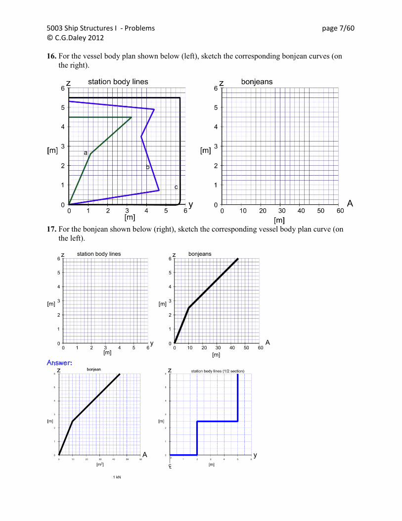
16. For the vessel body plan shown below (left), sketch the corresponding bonjean curves (on
the right).
17. For the bonjean shown below (right), sketch the corresponding vessel body plan curve (on
the left).
Answer:

5003 Ship Structures I - Problems page 8/60 © C.G.Daley 2012
18. Bonjean Curves The following figure shows 5 potential Bonjean curves. Some of them are
impossible. Identify the curves that can not be Bonjean curves and explain why. For the
feasible Bonjeans, sketch the x-section that the Bonjean describes.
a) is impossible – total Area can not diminish with increasing draft. b) is impossible – Area cant have multiple values ant any draft c) is impossible – Area can not be negative d) is impossible – Area can increase in a step (would imply infinite beam) e) is possible – as follows:
19. For the two ship stations shown below, sketch the corresponding bonjean curves on the grid
below.
5003 Ship Structures I - Problems page 9/60 © C.G.Daley 2012
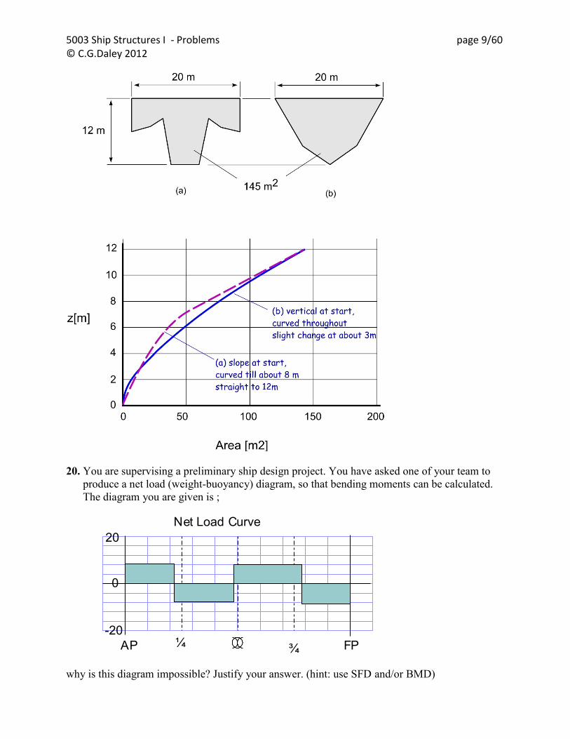
20. You are supervising a preliminary ship design project. You have asked one of your team to
produce a net load (weight-buoyancy) diagram, so that bending moments can be calculated.
The diagram you are given is ;
why is this diagram impossible? Justify your answer. (hint: use SFD and/or BMD)
AP
20
0
-20¼ FP
Net Load Curve
¾

5003 Ship Structures I - Problems page 10/60 © C.G.Daley 2012
21. For the three station profiles shown below, sketch the corresponding bonjean curves [4]

5003 Ship Structures I - Problems page 11/60 © C.G.Daley 2012
Chapter 5 – Longitudinal Strength - Still Water Moments.
22. Longitudinal strength is a primary concern during the design of a ship. Briefly explain the
idea behind Murray‟s Method. As a floating body, a ship has no fixed supports. The ship has a whole is in equilibrium with no net moments. However, any unbalanced moments in each half of the ship will be resisted by a similar moment from the other half. That moment will be transferred through midships and will be the midship bending moment. The moment from each half will arise if the center of weight (fwd half or aft half) is not directly over the center of buoyancy (fwd half or aft half). Murrays method makes use of empirical tables (based on Murrays assessment of actual ships) that estimate the location of the center of buoyancy of the fore (and aft) halves of the vessel. When combined with info or est. for the center of weights, the still water bending moment can be calculated. Murray assumed that the maximum bending moment would occur at midships, and could best be estimated by averaging the fore and aft contributions. 23. There is a „rectangular‟ shaped block of wood, as shown in the image below. The block
weighs 200 N and has uniform density. It is 1 m long and 0.20 m wide. It is 20 cm thick and
is floating in fresh water.
a) draw the shear force and bending moment diagrams for the block.

5003 Ship Structures I - Problems page 12/60 © C.G.Daley 2012
Now consider the addition of a small 50 N weight on the top of the block, at a distance 2/3m
from one end. (hint - a right triangle has its centroid at 2/3 of its length)
After the block settles to an equilibrium position -
b) Draw the bending moment and shear force diagrams
5003 Ship Structures I - Problems page 13/60 © C.G.Daley 2012
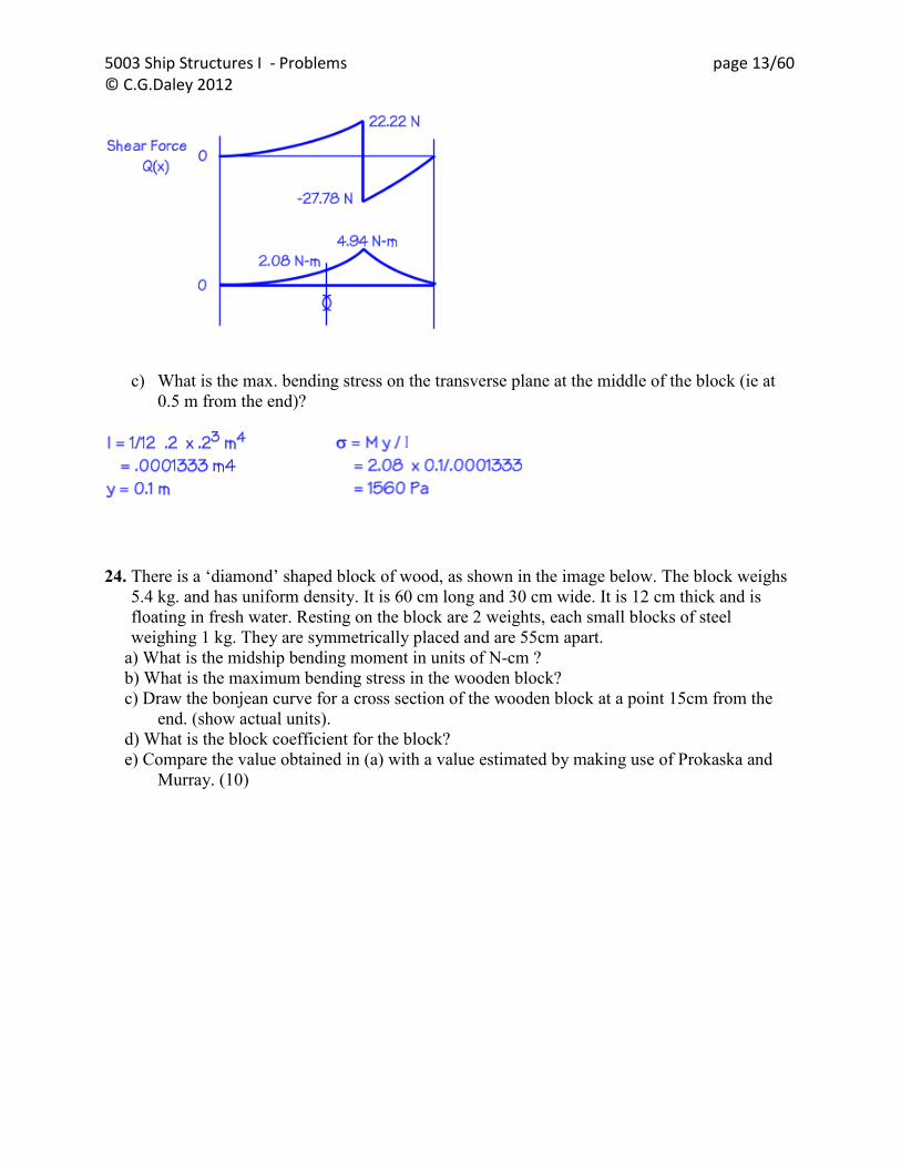
c) What is the max. bending stress on the transverse plane at the middle of the block (ie at
0.5 m from the end)?
24. There is a „diamond‟ shaped block of wood, as shown in the image below. The block weighs
5.4 kg. and has uniform density. It is 60 cm long and 30 cm wide. It is 12 cm thick and is
floating in fresh water. Resting on the block are 2 weights, each small blocks of steel
weighing 1 kg. They are symmetrically placed and are 55cm apart.
a) What is the midship bending moment in units of N-cm ?
b) What is the maximum bending stress in the wooden block?
c) Draw the bonjean curve for a cross section of the wooden block at a point 15cm from the
end. (show actual units).
d) What is the block coefficient for the block?
e) Compare the value obtained in (a) with a value estimated by making use of Prokaska and
Murray. (10)

5003 Ship Structures I - Problems page 14/60 © C.G.Daley 2012
ANS: a) 171.5 N-cm (hog) b) 23.8 MPa c) Straight and then vertical d) 0.5
a) The bending moment is 171.5 N-cm
b)
c) Bonjean:

5003 Ship Structures I - Problems page 15/60 © C.G.Daley 2012
d) The block coefficient is 0.5 (half the LxBxD is filled)
e)
5003 Ship Structures I - Problems page 16/60 © C.G.Daley 2012
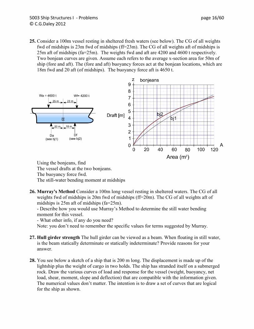
25. Consider a 100m vessel resting in sheltered fresh waters (see below). The CG of all weights
fwd of midships is 23m fwd of midships (ff=23m). The CG of all weights aft of midships is
25m aft of midships (fa=25m). The weights fwd and aft are 4200 and 4600 t respectively.
Two bonjean curves are given. Assume each refers to the average x-section area for 50m of
ship (fore and aft). The (fore and aft) buoyancy forces act at the bonjean locations, which are
18m fwd and 20 aft (of midships). The buoyancy force aft is 4650 t.
Using the bonjeans, find
The vessel drafts at the two bonjeans.
The buoyancy force fwd.
The still-water bending moment at midships
26. Murray's Method Consider a 100m long vessel resting in sheltered waters. The CG of all
weights fwd of midships is 20m fwd of midships (ff=20m). The CG of all weights aft of
midships is 25m aft of midships (fa=25m).
- Describe how you would use Murray‟s Method to determine the still water bending
moment for this vessel.
- What other info, if any do you need?
Note: you don‟t need to remember the specific values for terms suggested by Murray.
27. Hull girder strength The hull girder can be viewed as a beam. When floating in still water,
is the beam statically determinate or statically indeterminate? Provide reasons for your
answer.
28. You see below a sketch of a ship that is 200 m long. The displacement is made up of the
lightship plus the weight of cargo in two holds. The ship has stranded itself on a submerged
rock. Draw the various curves of load and response for the vessel (weight, buoyancy, net
load, shear, moment, slope and deflection) that are compatible with the information given.
The numerical values don‟t matter. The intention is to draw a set of curves that are logical
for the ship as shown.

5003 Ship Structures I - Problems page 17/60 © C.G.Daley 2012
29. You see below a sketch of a ship that is 200 m long. The displacement is made up of the
lightship plus the weight of cargo in two holds. The forward cargo hold is empty. Draw the
various curves of load and response for the vessel (weight, buoyancy, net load, shear,
moment, slope and deflection) that are compatible with the information given. The
numerical values don‟t matter. The intention is to draw a set of curves that are logical for the
ship as shown.
30. You see below a sketch of a ship that is 200 m long. The displacement is made up of the
lightship plus the weight of ballast in 4 tanks. The cargo holds are empty. Draw the various
curves of load and response for the vessel (weight, buoyancy, net load, shear, moment, slope
and deflection) that are compatible with the information given. The numerical values don‟t
matter. The intention is to draw a set of curves that are logical for the ship as shown.

5003 Ship Structures I - Problems page 18/60 © C.G.Daley 2012
31. Calculate the still water bending moment (in N-cm) for the solid block of plastic sketched
below. Assume the block has density as given and is floating in fresh water (density also
given). Is the moment hogging or sagging?
32. For the example of Murray‟s method in the Chapter, remove the cargo weight and add 4000
t of ballast, with a cg of 116m fwd of midship. Re-calculate the maximum sag and hog
moments (both still water and wave).
33. For the example of Murray‟s method in the Chapter, instead of using the weight locations as
given, assume that the weights are distributed according to Prohaska. Re-calculate the
SWBM.
34. Consider a 100m long tanker resting on an even keel (same draft fore and aft) in sheltered
waters. The CG of all weights is at midships and is 8000 tonnes.
Use Murray‟s Method and Prohaska‟s values to determine the still water bending moment
for this vessel (i.e. get both the weight and buoyancy BMs about midships).
A: First we can work out the buoyancy bending moment with Murray’s method.
We know that = 8000t, L=100 According to Murray, x_bar = L(a CB +b)

5003 Ship Structures I - Problems page 19/60 © C.G.Daley 2012
BMB = /2 * x_bar let CB = .9 (assume high value for tanker form)
We need to find T/L, we = L B T CB
If we assume B= 2.5T, we can write
= L B T CB
or 8000 = 100 2.5 T2 .9 so T = 6.96. This gives L/B=6.7, a reasonable value. And T/L = .06 From the Table we get a = .179, b=.063 x_bar = 100(.179 0.9 +.063) = 22.4m BMB = 4000 * 22.4 = 89640 t-m This is the buoyancy moment Now we need to estimate the weight moment. Prohaska tells us the shape of the weight distribution. w_bar = 8000t/100m = 80 t/m a= .75x80 = 60 t/m (initial intensity at end), b= 1.125 x 80 = 90t/m (over middle 1/3) We need to find the bending moment at midships for this weight. BMW = 60x100/3x(100/6+100/6) + 30x100/3x1/2x(100/6+100/9) + 90x100/6x100/12 = 93055 SWBM = 93055-89640 = 3415 t-m (hog) (tension in deck) ANS
C L 60 t/m
90 t/m
Half length = 50
5003 Ship Structures I - Problems page 20/60 © C.G.Daley 2012
Chapter 6 – Longitudinal Strength - Wave Bending Moments.
35. Using a spreadsheet, plot the design trochoidal wave for a 250m vessel, for the L/20 wave.
36. Using a spreadsheet, plot the design trochoidal wave for a 250m vessel, for the 1.1 L.5
wave.
37. Self Study – examine the SW/Wave spreadsheet (circulated).

5003 Ship Structures I - Problems page 21/60 © C.G.Daley 2012
Chapter 7: Longitudinal Strength: Inclined Bending / Section
Modulus
38. Find the moment of inertia of this compound section:
dimensions in mm
39. A box steel hull is 4m x 1m with a shell thickness of 10mm. It is inclined at 15 degrees, and
subject to a vertical bending moment of 2 MN-m. Find the bending stress at the emerged
deck edge.

5003 Ship Structures I - Problems page 22/60 © C.G.Daley 2012
Chapter 8: Beam Theory
40. Consider a beam made of steel joined to aluminum. The steel is 10 x 10 mm, with 5 x 10
mm of Aluminum attached. Esteel = 200,000 MPa, EAl = 80,000 MPa. The beam is fixed as
a simple cantilever, with a length of 100mm and a vertical force at the free end of 2 kN.
convert the section to an equivalent section in steel and calculate the equivalent moment of
inertia.
What is the deflection of the end of the beam (derive from 1st principles).
What is the maximum bending stress in the Aluminum at the support?
41. For elastic beam bending, derive the equation:
EI
M
dx
d
where is the slope of the deflected shape, M is the moment, E is Young's Modulus, I is the
moment of inertia. You can assume the =E and =My/I. Use at least one sketch.
42. Find and draw the shear force and bending moment diagrams for the following beam. Find
the values at supports and other max/min values.
43. There is a 3m beam. The shear force diagram is sketched below.
a) Sketch the load, moment, slope and deflection diagrams
b) What are the boundary conditions and discuss whether there can be more than one option
for the boundary conditions.

5003 Ship Structures I - Problems page 23/60 © C.G.Daley 2012
44. Consider a compound steel-aluminum beam, shown below. Calculate the deflection d (show
steps)
Ans: 0.112m

5003 Ship Structures I - Problems page 24/60 © C.G.Daley 2012
45. For elastic beam bending, complete Figure 1. The shear force diagram is sketched. You need
to infer from the shear what the load (including support reactions) may be, as well as an
estimate of the bending moment diagram, the slope diagram and the deflected shape. Draw
the support conditions and the applied load on the beam, and sketch the moment, slope and
deflection is the areas given.

5003 Ship Structures I - Problems page 25/60 © C.G.Daley 2012
46. Beam Mechanics. For the beam sketch below:
a) sketch by hand the shear, moment, slope and deflection diagrams
b) Assuming the beam is a 10cm x 10cm square steel bar, solve the problem to find the bending
stress at the fixed support. Use any method you like.

5003 Ship Structures I - Problems page 26/60 © C.G.Daley 2012
47. There is a length of steel that is 3.1416 m long, 50mm wide. It has a yield strength of 500
MPa (N/mm2), and a Young‟s Modulus of 200 GPa. If the steel is thin enough it can be bent
into a perfect circle without yielding.
a) What is the maximum thickness 't' for the steel to be bent elastically (and not yield)?
b) If the steel thickness is 1mm, what is the stress when it is bent into a 1m Dia circle.
c) What would the shear force diagram look like?
(Hint :this relates directly to the derivation of the differential equations for beam bending)

5003 Ship Structures I - Problems page 27/60 © C.G.Daley 2012
48. Sketch the shear, bending, slope and deflection patterns for the four cases shown below. No
numerical values are required.

5003 Ship Structures I - Problems page 28/60 © C.G.Daley 2012

5003 Ship Structures I - Problems page 29/60 © C.G.Daley 2012
Chapter 9: Beams, Frame and Structures
49. Solve the following beam. What is the maximum deflection (mm)? What is the maximum
stress (MPa) ?
ANS: .000136mm, 140 Pa
50. Solve the following beam. What is the maximum deflection (mm)? What is the maximum
stress (MPa) ?
ANS: .000484mm, 253 Pa
5003 Ship Structures I - Problems page 30/60 © C.G.Daley 2012
Chapter 10: Indeterminate Beams – Force Method
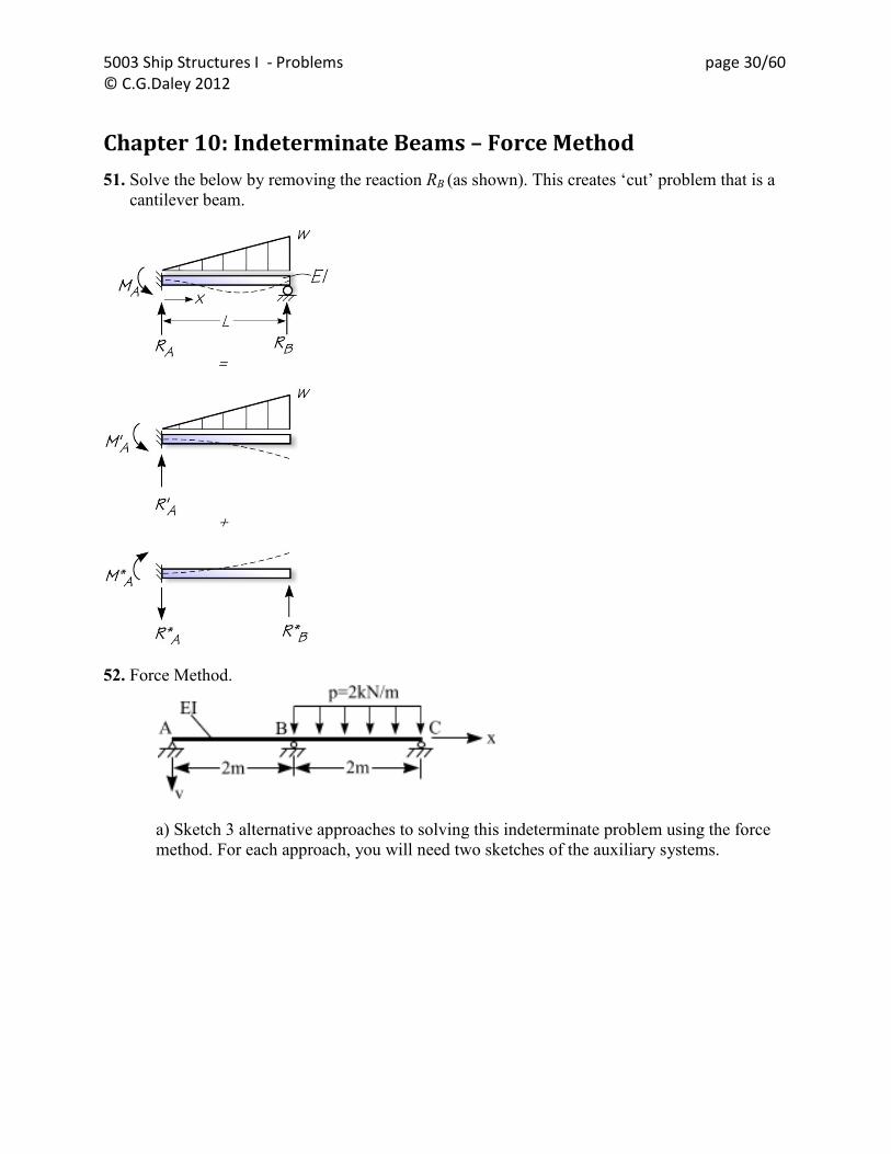
51. Solve the below by removing the reaction RB (as shown). This creates „cut‟ problem that is a
cantilever beam.
52. Force Method.
a) Sketch 3 alternative approaches to solving this indeterminate problem using the force
method. For each approach, you will need two sketches of the auxiliary systems.

5003 Ship Structures I - Problems page 31/60 © C.G.Daley 2012
b) Using one of the approaches sketched in a) , solve the system to find the reaction at B
(in kN)

5003 Ship Structures I - Problems page 32/60 © C.G.Daley 2012
Chapter 11: Indeterminate Beams – Displacement Method
53. Solve the pinned-pinned beam by using the displacement method as sketched below. The
solution for the fixed-fixed beam is the same as above. Then it is necessary to show that
MB*+MB**+MB***=0 and MA*+MA**+MA***=0. Note: MA** = ½ MB**, and MB*** =
½ MA***.
54. Describe how you would solve the beam shown below by using the displacement method.
55. For the simple beam shown below, derive the shear stiffness terms (i.e k15 to k65)

5003 Ship Structures I - Problems page 33/60 © C.G.Daley 2012
56. Solve the beam shown below using the stiffness method. Find the reactions at A and B, and
the deflection at B.
ANS: MA= 166667 N-m, MB = 83333N-m B = -.2082m

5003 Ship Structures I - Problems page 34/60 © C.G.Daley 2012
57. Stiffness method .
sketch a 2D beam and show the degrees of freedom.
Describe the meaning of the terms (any, all) in the 6x6 stiffness matrix for a 2D beam, and give
2 examples.
58. Explain the difference between the “Force” method, and the “Displacement” method.
59. In the stiffness method for a 2D beam, the standard value for the k22 stiffness term is;
Derive this equation (Table 1 in appendix may be useful).

5003 Ship Structures I - Problems page 35/60 © C.G.Daley 2012
Chapter 12: Energy Methods in Structural Analysis
60. Find the location of the force F so that is a maximum. Hint: you can use the symmetry of
Betti-Maxwell.
61. Illustrate the Betti-Maxwell theorem using the beam load cases shown below. Use the
deflection table on pg 8 at the end of the paper.
Solution: 21 is the rotation at the right hand end due to the force at the center. Assume the force has magnitude of one. 12 is the deflection at the center due to the moment at the right hand end. Assume the moment has magnitude of one
The beam deflection tables can be used to find 12 and 21 . The rotation 21 is as follows:

5003 Ship Structures I - Problems page 36/60 © C.G.Daley 2012
To find 1 2 we use the general equation for the deflections in a simply supported beam with an end moment and solve for the deflection at L/2 .
The two results are identical, as Betti-Maxwell predicted.

5003 Ship Structures I - Problems page 37/60 © C.G.Daley 2012
Chapter 13: The Moment Distribution Method
62. Moment distribution method
Solve the attached indeterminate beam problem by the Moment Distribution Method.
Complete 2 cycles of the solution.
EI=1
EI=6 m L=5 m L=4 m
2 m2 N/m2 N/m
2 m
2 N
63. Moment distribution method
Solve the attached indeterminate beam problem by the Moment Distribution Method.
Complete 2 cycles of the solution.
64. Moment distribution method. For the case shown on the attached page (Figure 1), fill in
the first two cycles of the MD calculations.
EI=1 EI=2EI=2L = 6 m L=5 m L=4 m
11 m
m22
NN
3 N
//
mm
2
2
m
m
2EI, L=6 EI, L=3
uniform load w=2, F=8/3, centered

5003 Ship Structures I - Problems page 38/60 © C.G.Daley 2012

5003 Ship Structures I - Problems page 39/60 © C.G.Daley 2012
65. For the statically indeterminate beam shown below, with the loads, properties and end
conditions as given,
a) Solve using the moment distribution method.
b) What is the vertical reaction at the middle support
2EI, L=6 EI, L=3
uniform load w=2, F=5
(at mid point)
5003 Ship Structures I - Problems page 40/60 © C.G.Daley 2012
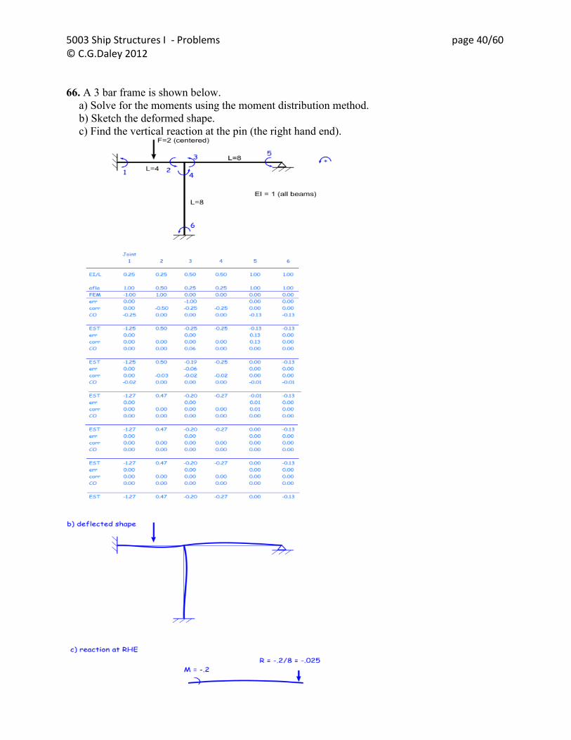
66. A 3 bar frame is shown below.
a) Solve for the moments using the moment distribution method.
b) Sketch the deformed shape.
c) Find the vertical reaction at the pin (the right hand end).
5003 Ship Structures I - Problems page 41/60 © C.G.Daley 2012
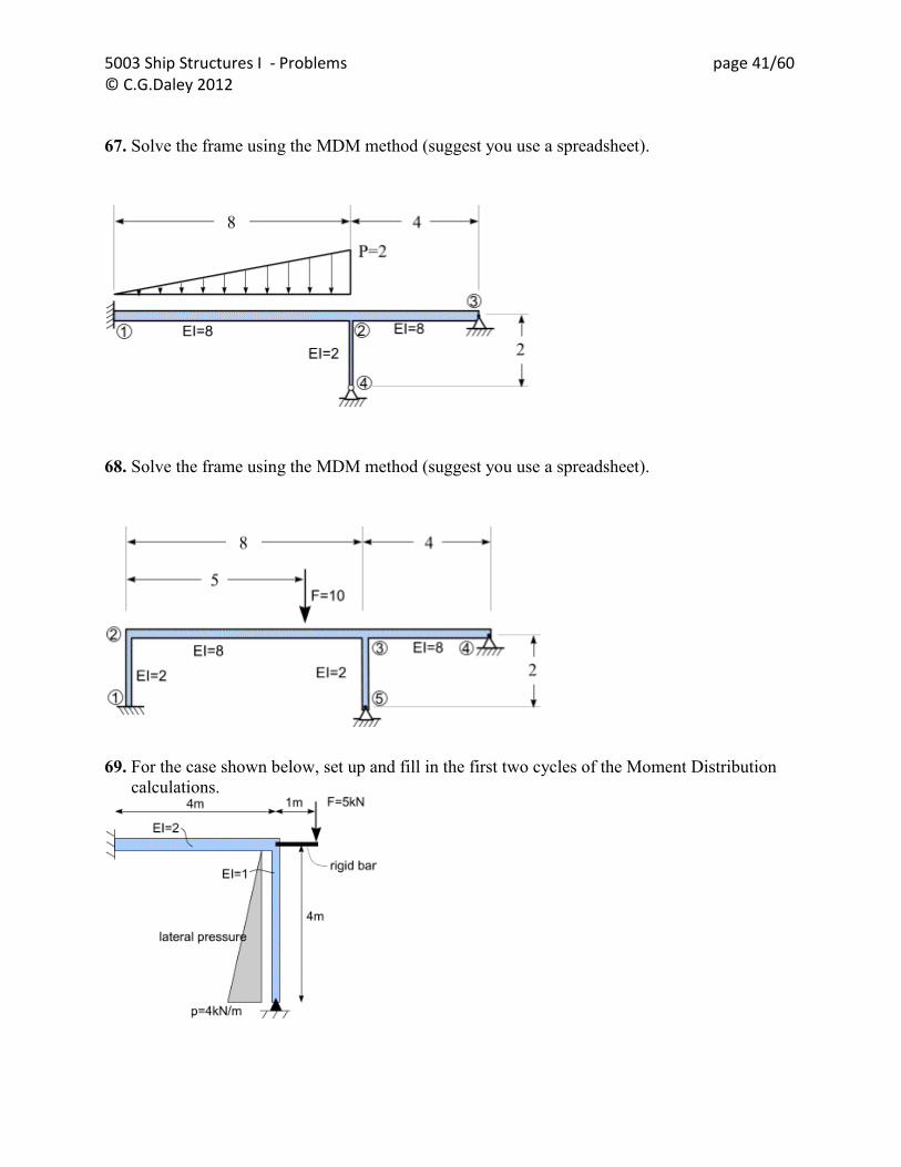
67. Solve the frame using the MDM method (suggest you use a spreadsheet).
68. Solve the frame using the MDM method (suggest you use a spreadsheet).
69. For the case shown below, set up and fill in the first two cycles of the Moment Distribution
calculations.
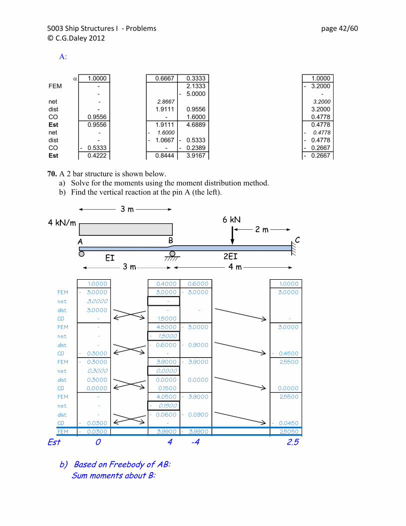
5003 Ship Structures I - Problems page 42/60 © C.G.Daley 2012
A:
70. A 2 bar structure is shown below.
a) Solve for the moments using the moment distribution method.
b) Find the vertical reaction at the pin A (the left).
Est 0 4 -4 2.5
b) Based on Freebody of AB: Sum moments about B:
1.0000 0.6667 0.3333 1.0000
FEM - 2.1333 3.2000-
- 5.0000- -
net - 2.8667 3.2000
dist - 1.9111 0.9556 3.2000
CO 0.9556 - 1.6000 0.4778
Est 0.9556 1.9111 4.6889 0.4778
net - 1.6000- 0.4778-
dist - 1.0667- 0.5333- 0.4778-
CO 0.5333- - 0.2389- 0.2667-
Est 0.4222 0.8444 3.9167 0.2667-
1.0000 0.4000 0.6000 1.0000 FEM 3.0000- 3.0000 3.0000- 3.0000 net 3.0000 - dist 3.0000 - - CO - 1.5000 - FEM - 4.5000 3.0000- 3.0000 net - 1.5000- dist - 0.6000- 0.9000- CO 0.3000- - 0.4500- FEM 0.3000- 3.9000 3.9000- 2.5500 net 0.3000 0.0000 dist 0.3000 0.0000 0.0000 CO 0.0000 0.1500 0.0000 FEM - 4.0500 3.9000- 2.5500 net - 0.1500- dist - 0.0600- 0.0900- CO 0.0300- - 0.0450- FEM 0.0300- 3.9900 3.9900- 2.5050

5003 Ship Structures I - Problems page 43/60 © C.G.Daley 2012
12kN x 1.5m – Fa x 3m -4kN-m = 0 Fa = (18-4)/3 = 4.666 kN < ANS

5003 Ship Structures I - Problems page 44/60 © C.G.Daley 2012
Chapter 14: The Moment Distribution Method with Sway
71. Solve the frame using the MDM method (suggest you use a spreadsheet).
72. A 3 bar frame is shown below.
Solve for the moments using the moment distribution method.
Sketch the deformed shape.
Find the vertical reaction at the pin (the right hand end).
5003 Ship Structures I - Problems page 45/60 © C.G.Daley 2012
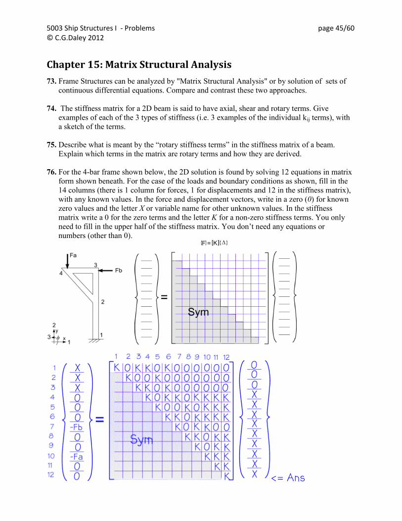
Chapter 15: Matrix Structural Analysis
73. Frame Structures can be analyzed by "Matrix Structural Analysis" or by solution of sets of
continuous differential equations. Compare and contrast these two approaches.
74. The stiffness matrix for a 2D beam is said to have axial, shear and rotary terms. Give
examples of each of the 3 types of stiffness (i.e. 3 examples of the individual kij terms), with
a sketch of the terms.
75. Describe what is meant by the “rotary stiffness terms” in the stiffness matrix of a beam.
Explain which terms in the matrix are rotary terms and how they are derived.
76. For the 4-bar frame shown below, the 2D solution is found by solving 12 equations in matrix
form shown beneath. For the case of the loads and boundary conditions as shown, fill in the
14 columns (there is 1 column for forces, 1 for displacements and 12 in the stiffness matrix),
with any known values. In the force and displacement vectors, write in a zero (0) for known
zero values and the letter X or variable name for other unknown values. In the stiffness
matrix write a 0 for the zero terms and the letter K for a non-zero stiffness terms. You only
need to fill in the upper half of the stiffness matrix. You don‟t need any equations or
numbers (other than 0).
<= Ans

5003 Ship Structures I - Problems page 46/60 © C.G.Daley 2012
77. A 2 part frame is shown below.
a) Construct the full structural stiffness matrix for the structure. Describe the steps you take
to do so. (12)
b) Write the force-deflection equation for the structure in matrix format, showing all terms
(ie include all terms in the matrices or vectors). Explain which, if any, terms are
unknown.(8)
a) The 6x6 standard matrix for the vertical beam is rotated by swapping dof 1 and 2 and 4 and 5
(rowns and columns are both swapped). The 6x6 for the top beam is in the usual orientation, except
that the dofs are numbered 4,5,6, 7,8,9. There are two terms for several dof at 4,5,6. The
combined Stiffness matrix is given below.
b) The reactions at dof 1,2,3,8 are unknown. The movements at 4,5,6,7,9 are unhlown. There are 9
unknowns in 9 dof, with 9 equations.

5003 Ship Structures I - Problems page 47/60 © C.G.Daley 2012
78. Assuming that you are using a program that performs matrix structural analysis, explain
concisely how the global stiffness terms for the joint circled in the sketch below are
determined. You don‟t have to solve this frame.
Writted discussion that should include topics such as –
Moment from A is fixed. The Stiffness terms for BC include axial, shear and rotation Same for BE, BE is rotated -90 deg BF only included axial , rotated (~45 deg),

5003 Ship Structures I - Problems page 48/60 © C.G.Daley 2012
Chapter 16 Overview of Finite Element Theory
79. The displacement functions of the constant stress triangular element are:
u(x,y) = C1 + C2 x + C3 y
v(x,y) = C4 + C5 x + C6 y
where u represents the x-translation of any point (x,y) and v represents the y-translation of the
point.
A beam has only one coordinate (x). However, most beam models would allow a point on the
beam to rotate as well as translate. So, construct 3 simple displacement functions;
u(x),
v(x),
(x),
of a „beam element‟, using the same logic as was used to create the displacement functions of
the constant stress triangular element.
Discuss the differences between this approac Chapter 16 – Problems

5003 Ship Structures I - Problems page 49/60 © C.G.Daley 2012
Chapter 17: Hull Girder Shear Stresses
80. An open section is shown below. This is the cross section of a long folded steel plate. The
cross section is subject to a shear force of 2 MN
a) Solve the shear flow, plot it and then also show the shear stress values.
b) If this is a section of a long cantilever (fixed at one end and free at the other) explain what
types of deformations would you expect to see.

5003 Ship Structures I - Problems page 50/60 © C.G.Daley 2012
81. An open section is shown below. This is the cross section of transverse frame in a ship The
shear force of 200kN
a) Solve the shear flow, plot it and then also show the shear stress values. (10)
b) The web is welded to the shell plate. What shear force must be resisted at this joint? (5)
a) Shear Flow – Start by finding I A = 90 cm3 Base line in center of shell plate I_base = 4650 cm4 h_na = 3.667 cm I_na = 3440 cm4 Q = 0.2 MN q = Qm/I_na Shear Flow and Stress sloution:
b) Shear in Joint – 77.4 MPa = becomes shear force of 11.61kN per cm.

5003 Ship Structures I - Problems page 51/60 © C.G.Daley 2012
Chapter 18: Shear Stresses in multi-cell sections
82. Solve the shear flow in the following section of a tanker. Ignore the radius of the bilge.

5003 Ship Structures I - Problems page 52/60 © C.G.Daley 2012
Chapter 19: Shear Flow in adjacent Closed Cells
83. Solve the shear flow in the following section of a tanker. Ignore the radius of the bilge.

5003 Ship Structures I - Problems page 53/60 © C.G.Daley 2012
Chapter 20: Torsion in ships
84. A hollow closed section is made of plate of uniform thickness „t‟ . A torsional moment of 80
MN-m is applied. To have the maximum shear stress equal to 135 MPa, what value should t
be ?

5003 Ship Structures I - Problems page 54/60 © C.G.Daley 2012
Chapter 21: Shear Center and Shear Lag in Ship Structures
85. The following figure shows 4 x-sections. Identify the location of the shear center in each
case (i.e which letter?). You should sketch the shear flow to help identify the location.
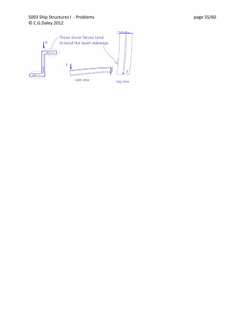
86. When the vertical force F is applied to this section, how will the cantilever beam deform?
Explain
5003 Ship Structures I - Problems page 55/60 © C.G.Daley 2012

5003 Ship Structures I - Problems page 56/60 © C.G.Daley 2012
Chapter 22: Plate Bending

5003 Ship Structures I - Problems page 57/60 © C.G.Daley 2012
Chapter 23: Hull Girder Stress Assessment
87. Ship strength (indicate if true or false, and provide an explanatory comment)
[ T,F]
a) structural design determines the principal dimensions of a ship.
comment:
b) The only static loads are those that result from gravity.
comment:
c) All forces on a ship are in balance, unless there are large waves.
comment:
d) Shell plating is called 'primary structure'.
comment:
e) Simple beam theory ignores shear stresses.
comment:
f) Murray's Method is a quick way to obtain wave bending moments.
comment:
g) The Prohaska method is used to estimate buoyancy.
comment:
h) The Moment distribution method will not work if the structure is
indeterminate.
comment:
i) Trochoidal waves have relatively steep crests and shallow troughs.
comment:
i) A tee stiffener is an open section.
comment:

5003 Ship Structures I - Problems page 58/60 © C.G.Daley 2012
Appendix
Formulae Weight of a Vessel:
Prohaska for parallel middle body : the values of a and b are ;
Tankers (CB = .85) .75 1.125
Full Cargo Ships (CB = .8) .55 1.225
Fine Cargo Ships (CB=.65) .45 1.275
Large Passenger Ships (CB=.55) .30 1.35
Murray‟s Method
Where
This table for a and b can be represented adequately by the equation;
b = 1.1 T/L -.003
Trochoidal Wave Profile
Section Modulus Calculations Ina = 1/12 a d2
= 1/12 t b3 cos2
Family of Differential Equations Beam Bending
deflection [m]
slope [rad]
bending moment [N-m]
shear force [N]
line load [N/m]
Stiffness Terms
TBLCW B
L
WW hull
W
a
W
b
54
7L
W
xlcg
xggBM ffaaB 2
1
2
1
)( bCaLx B
LTa /239.
sinrRx
)cos1( rz
v
v
MEIv
QEIv
PEIv
T/L a b
.03 .209 .03
.04 .199 .041
.05 .189 .052
.06 .179 .063
= rolling angle
2D beam = 6 degrees of freedom
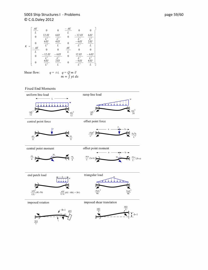
5003 Ship Structures I - Problems page 59/60 © C.G.Daley 2012
Shear flow: q = t, q = Q m /I
L
EI
L
EI
L
EI
L
EIL
EI
L
EI
L
EI
L
EIL
AE
L
AEL
EI
L
EI
L
EI
L
EIL
EI
L
EI
L
EI
L
EIL
AE
L
AE
K
460
260
6120
6120
0000
260
460
6120
6120
0000
22
2323
22
2323

5003 Ship Structures I - Problems page 60/60 © C.G.Daley 2012

![MEMORIAL UNIVERSITY OF NEWFOUNDLAND ......Memorial University of Newfoundland Statement 2 Year ended March 31 [thousands of dollars] 2015 2014 REVENUE Government grants 440,879 444,274](https://static.fdocuments.in/doc/165x107/5f796dc30e081606d3014a47/memorial-university-of-newfoundland-memorial-university-of-newfoundland.jpg)