Probabilistic failure analysis of underground flexible...
17
Structural Engineering and Mechanics, Vol. 47, No. 2 (2013) 167-183 DOI: http://dx.doi.org/10.12989/sem.2013.47.2.167 167 Copyright © 2013 Techno-Press, Ltd. http://www.techno-press.org/?journal=sem&subpage=8 ISSN: 1225-4568 (Print), 1598-6217 (Online) Probabilistic failure analysis of underground flexible pipes Kong Fah Tee , Lutfor Rahman Khan and Hua-Peng Chen Department of Civil Engineering, University of Greenwich, UK (Received August 24, 2012, Revised May 21, 2013, Accepted July 3, 2013) Abstract. Methods for estimating structural reliability using probability ideas are well established. When the residual ultimate strength of a buried pipeline is exceeded the limit, breakage becomes imminent and the overall reliability of the pipe distribution network is reduced. This paper is concerned with estimating structural failure of underground flexible pipes due to corrosion induced excessive deflection, buckling, wall thrust and bending stress subject to externally applied loading. With changes of pipe wall thickness due to corrosion, the moment of inertia and the cross-sectional area of pipe wall are directly changed with time. Consequently, the chance of survival or the reliability of the pipe material is decreased over time. One numerical example has been presented for a buried steel pipe to predict the probability of failure using Hasofer-Lind and Rackwitz-Fiessler algorithm and Monte Carlo simulation. Then the parametric study and sensitivity analysis have been conducted on the reliability of pipeline with different influencing factors, e.g. pipe thickness, diameter, backfill height etc. Keywords: probability of failure; flexible pipes; Hasofer-Lind and Rackwitz-Fiessler algorithm; Monte Carlo simulation; deflection; buckling; wall thrust; bending stress 1. Introduction Failure management of buried pipeline systems is one of the important issues for asset managers. A large section of pipes in the UK are classified as structurally deficient and functionally obsolete. Every year billions of pounds are spent by water industries for their maintenance and renewal. Due to their low visibility, condition assessment and rehabilitation of the underground pipelines are frequently neglected. Lack of detailed knowledge on the condition of pipelines escalates vulnerability to catastrophic failures (Chughtai and Zayed 2008). The behaviour of buried pipes is considerably influenced by uncertainties due to external loads, pipe materials and surrounding soil properties etc. The decision to repair or replace current pipe is typically based on performance indicators such as structural integrity, hydraulic efficiency and system reliability (Rajani and Makar 2000). Ahammed and Melchers (1994) stated that the pipe replacement or rehabilitation is typically determined by the performance parameter, i.e. the annual number of failure in a given section of pipe networks. This approach depends largely on what has happened in the past and what is expected to happen in the future. A complicated approach to scheduling pipe maintenance is to determine individual pipes that are approaching unsafe condition and repair or replace them before they fail. This type of approach Corresponding author, Ph.D., E-mail: [email protected]
Transcript of Probabilistic failure analysis of underground flexible...
Structural Engineering and Mechanics, Vol. 47, No. 2 (2013) 167-183
DOI: http://dx.doi.org/10.12989/sem.2013.47.2.167 167
Copyright © 2013 Techno-Press, Ltd.
http://www.techno-press.org/?journal=sem&subpage=8 ISSN: 1225-4568 (Print), 1598-6217 (Online)
Probabilistic failure analysis of underground flexible pipes
Kong Fah Tee, Lutfor Rahman Khan and Hua-Peng Chen
Department of Civil Engineering, University of Greenwich, UK
(Received August 24, 2012, Revised May 21, 2013, Accepted July 3, 2013)
Abstract. Methods for estimating structural reliability using probability ideas are well established. When the residual ultimate strength of a buried pipeline is exceeded the limit, breakage becomes imminent and the overall reliability of the pipe distribution network is reduced. This paper is concerned with estimating structural failure of underground flexible pipes due to corrosion induced excessive deflection, buckling, wall thrust and bending stress subject to externally applied loading. With changes of pipe wall thickness due to corrosion, the moment of inertia and the cross-sectional area of pipe wall are directly changed with time. Consequently, the chance of survival or the reliability of the pipe material is decreased over time. One numerical example has been presented for a buried steel pipe to predict the probability of failure using Hasofer-Lind and Rackwitz-Fiessler algorithm and Monte Carlo simulation. Then the parametric study and sensitivity analysis have been conducted on the reliability of pipeline with different influencing factors, e.g. pipe thickness, diameter, backfill height etc.
Keywords: probability of failure; flexible pipes; Hasofer-Lind and Rackwitz-Fiessler algorithm; Monte
Carlo simulation; deflection; buckling; wall thrust; bending stress
1. Introduction
Failure management of buried pipeline systems is one of the important issues for asset
managers. A large section of pipes in the UK are classified as structurally deficient and
functionally obsolete. Every year billions of pounds are spent by water industries for their
maintenance and renewal. Due to their low visibility, condition assessment and rehabilitation of
the underground pipelines are frequently neglected. Lack of detailed knowledge on the condition
of pipelines escalates vulnerability to catastrophic failures (Chughtai and Zayed 2008). The
behaviour of buried pipes is considerably influenced by uncertainties due to external loads, pipe
materials and surrounding soil properties etc. The decision to repair or replace current pipe is
typically based on performance indicators such as structural integrity, hydraulic efficiency and
system reliability (Rajani and Makar 2000). Ahammed and Melchers (1994) stated that the pipe
replacement or rehabilitation is typically determined by the performance parameter, i.e. the annual
number of failure in a given section of pipe networks. This approach depends largely on what has
happened in the past and what is expected to happen in the future.
A complicated approach to scheduling pipe maintenance is to determine individual pipes that
are approaching unsafe condition and repair or replace them before they fail. This type of approach
Corresponding author, Ph.D., E-mail: [email protected]

Kong Fah Tee, Lutfor Rahman Khan and Hua-Peng Chen
requires a robust methodology to determine the remaining safe service life of each pipe segment
within the distribution network system. Many challenges have faced by water industry during
placing or maintenance the underground pipeline networks. The most common challenges are
found as buckling, deflection, wall thrust and bending behaviour of pipe under hydrostatic
pressure, poor design detailing and installation practices during placing the pipes, insufficient
corrosion protection procedures, pipe material deterioration, scouring underneath the ground level,
frost heave action and insufficient understanding of the product limitations. In reality, a buried
pipe‟s mechanical strength begins to decrease as soon as it is installed because of the
environmental conditions surrounding the pipe. Due to their low visibility and lack of proper
information regarding underground pipes‟ condition, assessment and maintenance are frequently
neglected until a disastrous failure occurs. The long-term planning of the renewal of underground
pipe distribution networks requires the ability to predict system reliability as well as assess the
economic impact (Tee and Li 2011).
For buried pipelines subject to both internal and external loading, a vital failure criterion is the
loss of structural strength which is influenced by localized or overall reduction in pipe wall
thickness (Ahammed and Melchers 1997). The size of the resulting thickness undermines the pipe
resistance capacity which in turn reduces the factor of safety of the whole distribution system. In
the past, various researchers and organizations recognized the importance and the applicability of
probabilistic approach in the reliability estimation of buried flexible pipeline systems. The
development of reliability analysis in pipe systems is receiving considerable attention nowadays
and the guidelines on the targeted reliability indices have been suggested recently. Methods of
reliability analysis such as first order reliability method (FORM), second-order reliability method
(SORM), point estimate method, and Monte Carlo simulation are available in literature (Baecher
and Christian 2003). Complex models in risk and reliability analysis often involve uncertain input
parameters which can be determined using these methods with varying degrees of accuracy. These
parameters are best explained by random variables with known or assumed probability
distributions.
Babu and Rao (2005) conducted reliability analysis on flexible buried steel pipe in terms of two
failure modes, namely, deflection and buckling. Later, Babu et al. (2006) predicted the
underground flexible pipe failure due to deflection, buckling and wall thrust. These analyses were
based on pipe installation time only, i.e., non-time dependent. Hence, the practical motivation of
this study is to investigate these different failure modes with respect to time. In reality,
underground pipeline failure is a continuous and time-variant process. The strength of buried metal
pipe decreases due to corrosion, fatigue and overloading and this affects the pipe reliability over
time. As a result, the safety or serviceability margin and the corresponding reliability index
decreases (or failure probability increases) with respect to time. Since the life of an underground
pipeline is related to corrosion deterioration and the developed stresses, the available design
equations (ASCE 2001, Gabriel 2011) for pipeline as well as pipeline thickness loss due to
corrosion are used for the purpose of establishing a probabilistic functional relationship between
loads, corrosion, related soil and material random variables. In the probabilistic approach, the
input parameters are treated as continuous random variables and the performance of the structure
resulting from different failure criteria is expressed in a probabilistic pipeline framework, i.e.,
either probability of failure or in terms of reliability index. The key component of this
methodology is to estimate the probability of failure to predict the expected residual safe service
life of pipes. Therefore, this paper focuses on the results of the analysis of the buried flexible pipes
conducted in the light of the aforementioned points and has the following objectives:
168
Probabilistic failure analysis of underground flexible pipes
(a) The failure probability analysis of buried flexible pipe system from different failure criteria,
i.e., excessive deflection, buckling, wall thrust, bending stress and strain based on the available
conventional design equations.
(b) Comparative study of safety in terms of probability of failure or survival time for flexible
pipes in different failure modes and parametric analysis for different influencing factors.
2. Formulation for prediction of pipe failure
2.1 Corrosion of flexible steel pipes
Buried pipes are made of plastic, concrete or metal, e.g. steel, galvanized steel, ductile iron,
cast iron or copper. Plastic pipes tend to be resistant to corrosion. Damage in concrete pipes can be
attributed to biogenous sulphuric acid attack (Tee et al. 2011). On the other hand, metal pipes are
susceptible to corrosion. Metal pipe corrosion is a continuous and variable process. Under certain
environmental conditions, metal pipes can become corroded based on the properties of the pipe,
the soil surrounding the pipe wall, water or wastewater properties and stray electric currents. The
corrosion pit depth DT
can be modelled with respect to time as follows (Ahammed and Melchers
1994, Sadiq et al. 2004)
n
T kTD (1)
where k is multiplying constant, n is exponential constant and T is exposure time. For
simplification, the corrosion pit depth is considered as uniform around the entire circumference of
the pipe and based on this assumption, moment of inertia, I and cross-sectional area of pipe wall
per unit length, As are shown in Eqs. (2) and (3) respectively (Watkins and Anderson 2000)
I = (t – DT) 3/12 (2)
As = t –DT (3)
In this study, DT, I and As are time dependent variables. The corrosion parameters k and n are
highly uncertain and therefore are treated as random variables in the reliability analysis. These
values are typically determined from regression analysis using observed and experimental data
obtained for specific soil and other conditions. When there is little or no information on which to
base a choice for corrosion constant parameters, then known values from other situations might be
used, with judicious selection of means and variances (Ahammed and Melchers 1994).
2.2 Flexible pipe failure modes
Pipe behaviour can be broadly classified as flexible or rigid, depending on how it performs
when installed. All types of underground pipes whether flexible or rigid, rely on the backfill
properties to transfer the loads into the bedding. Structures collapse when the applied stress
exceeds the limiting or ultimate strength of the pipe wall material. In this paper, the dominating
failure criteria of flexible pipes are characterised by limit states as follows
(a) Excessive deflection;
(b) Actual buckling pressure greater than the critical buckling pressure;
(c) Actual wall thrust greater than critical wall thrust;
169

Kong Fah Tee, Lutfor Rahman Khan and Hua-Peng Chen
(d) Actual bending stress greater than the allowable stress.
2.2.1 Deflection The performance of flexible pipe in its ability to support load is typically assessed by
measuring the deflection from its initial shape. Deflection can be defined as the change in inside
diameter that results when a load is applied to a flexible pipe. Deflection is quantified in terms of
the ratio of the horizontal increase in diameter (or vertical decrease in diameter) to the pipe
diameter. Rigid pipe is sometimes classified as pipe that cannot deflect more than 2% without
significant structural distress, such as cracking. Flexible pipe takes advantages of its ability to
move, or deflect under loads without structural damage. The critical deflection for flexible pipe,
∆ycr is determined as 5% of inside diameter of pipe (Gabriel 2011). According to BS EN 1295:1
(1997) and BS 9295 (2010) the deflection, ∆y can be calculated as below
s
scL
ED
EI
DPWDKy
061.08
)(
3
(4)
where K is deflection coefficient, DL is deflection lag factor, D is mean diameter, E is modulus of
elasticity of pipe material and E‟ is modulus of soil reaction. The deflection coefficient reflects the
degree of support provided by the soil which is based on the type of installation. The loads acting
on the pipe are governed by the term DLWC + PS where WC is soil load and PS is live load as
follows
HW sc (5)
21 LL
IWP
fS
S (6)
where γs is unit weight of the soil, H is height of soil on the top of pipe, WS is wheel load, If is
impact factor with the value of 1.1 for 0.6 m < H < 0.9 m, or 1 for H 0.9 m, L1 and L2
are load
width parallel and perpendicular to direction of travel, respectively (Sarplast 2008).
2.2.2 Buckling External loadings from soil pressure or external hydrostatic pressure can cause inward
deformation known as wall buckling. Buckling is a premature failure in which the pipe is not able
to maintain its initial circular shape when the tangential compressive stress reaches a limit value
and the pipe distorts unstably in buckling. Wall buckling can occur due to insufficient pipe
stiffness. The more flexible the pipe, the more unstable the wall structure will be in resisting wall
buckling. Pipe encased in soil may buckle due to excessive loads and deformations.
The two buckling forms are usually called general (global) buckling and local buckling (Berti
et al. 1998). Global buckling is a load response mode due to compressive effective axial force but
not a failure mode. Pipe is safe from buckle globally whereas local buckling is an important limit
state. The total load or the actual buckling pressure must be less than the critical buckling pressure
for the safety of the structure. The actual buckling pressure for flexible pipe, p can be calculated as
follows (AWWA 1999)
170

Probabilistic failure analysis of underground flexible pipes
Swwsw PHRp (7)
where Rw is water buoyancy factor, γw is unit weight of water, Hw is height of groundwater above
pipe springline and PS is live load as calculated in Eq. (6). The critical buckling pressure pcr is
calculated as follows (AWWA 1999)
3
'321
D
EIEBR
Sp sw
f
cr (8)
where Sf is safety factor, Es is soil modulus and B‟ is empirical coefficient of elastic support. The
critical buckling pressure depends on the surrounding soil pressure. The critical buckling pressure
increases/decreases as the effective soil pressure surrounding the pipe increases/decreases.
2.2.3 Wall thrust Wall thrust or wall crushing is characterised by localised yielding when the in-wall stress
reaches the yield stress of the pipe material. If the buried depth is not enough then the pipe wall
can crush due to earth and surface loading. Buried depth should be sufficient to avoid the crushing
of the side wall. Thrust or stress on the pipe wall is the total load on the pipe wall including soil
loads, traffic loads and hydrostatic loads. If only dead load is involved during the installation, the
long-term material properties are considered throughout the calculation of wall thrust analysis.
However, if both dead load and live load are present (typically any vehicular load with 2.4 m of
cover or less), two wall thrust analyses are required (Gabriel 2011) as follows
(a) Accounts both dead load and live load and employs the short term material properties
throughout the procedure;
(b) Accounts only dead load and employs the long-term material properties throughout the
process.
Then, the more conservative limit state function value is used for wall thrust analysis. Note that
some flexible pipes have both short-term and long-term material properties (elasticity of modulus),
where short-term value is higher than long-term value, such as, polyethylene pipe and therefore,
two wall thrust analyses are applicable but some have no such classification, for example, ductile
iron pipes, steel pipes etc. and for these cases, only above option a) is considered for analysis,
where short-term and long-term properties are the same.
The critical and actual wall thrust can be estimated by applying Eq. (9) and Eq. (10),
respectively (Gabriel 2011). The allowable or critical thrust must be equal to or greater than the
actual thrust in order to remain structurally stable.
The critical wall thrust
psycr AFT (9)
where Fy is the minimum tensile strength of pipe, As is cross-sectional area of pipe wall per unit
length and p is capacity modification factor for pipe.
The actual wall thrust
)2/)(67.15.1(3.1 owLSA DPCPWT (10)
where Do is the outside diameter and CL is live load distribution coefficient. The loads acting on
the pipe considered in wall thrust analysis are soil arch load WA, live load PS and hydrostatic
171

Kong Fah Tee, Lutfor Rahman Khan and Hua-Peng Chen
pressure Pw which can be calculated as follows
AFspA VPW (11)
gwW HP (12)
where Psp is geostatic load, VAF is vertical arching factor and Hg is height of groundwater above
springline of pipe.
2.2.4 Bending stress and bending strain The moment curvature relationship provides information necessary for pipe design against
failure due to bending. If a pipe is part of a carrying structure, the elastic limit may be an obvious
choice as the design limit. A pipe subjected to increasing pure bending will fail as a result of
increased ovalisation of the cross section and reduced slope in the stress-strain curve. Up to a
certain level of ovalisation, the decrease in moment of inertia will be counterbalanced by increased
pipe wall stresses due to strain hardening. When the loss in moment of inertia can no longer be
compensated for by the strain hardening, the moment capacity has been reached and catastrophic
cross sectional collapse will occur if additional bending is applied (Hauch and Bai 1999).
For the safety of the pipe, the bending stress should not exceed the tensile strength of the pipe
material and the longitudinal bending strain should not exceed the allowable strain limit of pipe
materials. Therefore, checking the bending stress and strain is important to ensure that these are
within material capability. Bending stress σb and bending strain εb can be calculated as follows
(Gabriel 2011)
2
0 /2 DSyED fyfb (13)
2
0 /2 DSyD fyfb (14)
where Df is shape factor, y0 is distance from centroid of pipe wall to the furthest surface of the
pipe.
3. Probabilistic reliability analysis
Monte Carlo simulation (MCS) and Hasofer-Lind and Rackwitz-Fiessler (HLRF) algorithm are
used in this study for estimating structural reliability of underground flexible pipes. Pipe failure
can be defined in relation to different possible mechanisms as mentioned in Section 2. The limit
state functions for the failure modes are defined as follows
yyXZ cr )( (for deflection) (15)
ppXZ cr )( (for buckling) (16)
TTXZ cr )( (for wall thrust) (17)
bcrXZ )( (for bending stress) or bcrXZ )( (for bending strain) (18)
where Δycr, pcr, Tcr, σcr and εcr are critical pipe deflection, buckling, wall thrust, bending stress and
172
Probabilistic failure analysis of underground flexible pipes
bending strain, respectively whereas Δy, p, T, σb and εb are actual pipe deflection, buckling, wall
thrust, bending stress and bending strain, respectively.
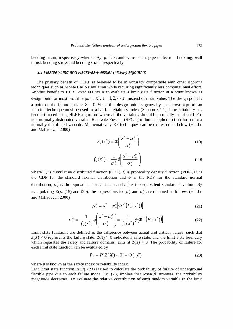
3.1 Hasofer-Lind and Rackwitz-Fiessler (HLRF) algorithm
The primary benefit of HLRF is believed to lie in accuracy comparable with other rigorous
techniques such as Monte Carlo simulation while requiring significantly less computational effort.
Another benefit to HLRF over FORM is to evaluate a limit state function at a point known as
design point or most probable point nixi ,,2,1,* instead of mean value. The design point is
a point on the failure surface Z = 0. Since this design point is generally not known a priori, an
iteration technique must be used to solve for reliability index (Section 3.1.1). Pipe reliability has
been estimated using HLRF algorithm where all the variables should be normally distributed. For
non-normally distributed variable, Rackwitz-Fiessler (RF) algorithm is applied to transform it to a
normally distributed variable. Mathematically RF techniques can be expressed as below (Haldar
and Mahadevan 2000)
e
x
e
xx
xxF
** )( (19)
e
x
e
x
e
x
x
xxf
** 1)( (20)
where Fx is cumulative distributed function (CDF), fx is probability density function (PDF), Φ is
the CDF for the standard normal distribution and is the PDF for the standard normal
distribution, ex is the equivalent normal mean and e
x is the equivalent standard deviation. By
manipulating Eqs. (19) and (20), the expressions for ex and e
x are obtained as follows (Haldar
and Mahadevan 2000)
)( *1* xFx x
e
x
e
x
(21)
)()(
1
)(
1 *1
*
*
*xF
xf
x
xfx
x
e
x
e
x
x
e
x
(22)
Limit state functions are defined as the difference between actual and critical values, such that
Z(X) < 0 represents the failure state, Z(X) > 0 indicates a safe state, and the limit state boundary
which separates the safety and failure domains, exits at Z(X) = 0. The probability of failure for
each limit state function can be evaluated by
)(]0)([ XZPPf (23)
where β is known as the safety index or reliability index.
Each limit state function in Eq. (23) is used to calculate the probability of failure of underground
flexible pipe due to each failure mode. Eq. (23) implies that when β increases, the probability
magnitude decreases. To evaluate the relative contribution of each random variable in the limit
173

Kong Fah Tee, Lutfor Rahman Khan and Hua-Peng Chen
state function Z(X), sensitivity coefficient 2
ix can be calculated as follows
2
1
2*
*
2
n
i
e
x
i
e
x
i
x
x
Z
x
Z
i
(24)
3.1.1 Procedure HLRF algorithm is described briefly as follows
Step 1: Define an appropriate limit state equation.
Step 2: Assume an initial value of the safety index β. Any value of β can be assumed. If it is
chosen intelligently, the algorithm will converge in a very few steps. An initial β value of 3.0 is
reasonable.
Step 3: Assume the initial values of the design point *
ix . In the absence of any other
information, the initial design point can be assumed to be at the mean values of the random
variables.
Step 4: Compute the mean and standard deviation at the design point of the equivalent normal
distribution. Apply Rackwitz-Fiessler algorithm for those variables that are non-normal.
Step 5: Compute partial derivatives *)/( ixZ evaluated at the design point
*
ix .
Step 6: Compute the direction cosines αi at the design point as
n
i
e
x
i
e
x
i
x
x
Z
x
Z
i
1
2*
*
If the random variables are normal, then their standard deviations can be used directly;
otherwise, for non-normal random variables, the equivalent standard deviations at the design point
need to be used.
Step 7: Compute the new values for design point *
ix as
e
xi
e
xix *
If necessary, repeat steps 4 through 7 until the estimates of αi converge to a predetermined
tolerance. A tolerance level of 0.001 - 0.005 is common.
Step 8: Compute an updated value for β using the condition that limit state equation must be
satisfied at the new design point.
Step 9: Repeat steps 3 through 8 until β converges to a predetermined tolerance level.
Step 10: Calculate the failure probability Pf using Eq. (23).
3.2 Monte Carlo simulation (MCS)
174

Probabilistic failure analysis of underground flexible pipes
Fig. 1 Geometrical details of the buried flexible pipe section
The probability of failure, Pf is expressed by Eq. (23) or the following expression
(25)
where X1, X2, ..., Xn are random variables. The Monte Carlo simulation allows the determination of
an estimate of the probability of failure, given by
(26)
where I(X1, X2, ..., Xn ) is a function defined by
0),,,(0
0),,,(1),,,(
21
21
21
n
n
nXXXgif
XXXgifXXXI
(27)
According to Eq. (26), N independent sets of values X1, X2, ..., Xn are generated based on the
probability distribution of each random variable and the failure function is computed for each
sample. Using MCS, the probability of structural failure is estimated as follows
N
NP H
f (28)
where NH is the total number of cases where failure has occurred.
4. Numerical studies
An underground steel pipe with a mean diameter of 1.21 m and initial wall thickness of 21 mm
under a roadway subjected to hypothetical operating conditions is taken as a numerical example.
Calculations are presented for the case of a typical pipe section, as shown in Fig. 1. The pipe is
circular and buried in a trench of 2 m width and 3.75 m depth. The backfill material has a unit
]0),,,([ 21 nf XXXZPP
),,.,(1
1
21
N
i
nf XXXIN
P
175

Kong Fah Tee, Lutfor Rahman Khan and Hua-Peng Chen
Table 1 Properties and parameters
Symbol description Value
Buoyancy factor, Rw 1.00
Trench width, Bd 2.00 m
Outside pipe diameter, Do 1.231 m
Inside pipe diameter, DI 1.189 m
x-sectional area of pipe wall per unit length, As 0.021 m2/m
Shape factor, Df 4.0
Capacity modification factor for pipe, p 1.00
Safety factor for bending, Sf 1.5
Tensile strength of pipe, Fy 450 MPa
Safety factor for Buckling, Sf 2.5
Poisson Ratio, υ 0.3
Allowable Strain, cr 0.2%
Table 2 Statistical properties of random variables
Material properties Mean (μ) COV* (%) Distribution
Elastic modulus of pipe, E 213.74×10⁶ kPa 1.0 Normal
Backfill soil modulus, Es 103 kPa 5.0 Normal
Unit of weight of soil, s 18.0kN/m3 2.5 Normal
Wheel load (Live load), Ps 80.0 kPa 3.0 Normal
Deflection coefficient, K 0.11 1.0 Lognormal
Multiplying constant, k 2.0 10.0 Normal
Exponential constant, n 0.3 5.0 Normal
Thickness of pipe, t 0.021 m 1.0 Normal
Height of the backfill, H 3.75 m 1.0 Normal
*COV = Coefficient of Variation
weight of 18.0 kN/m3 and soil modulus of 10
3 kPa. The buried pipe is considered under a heavy
traffic condition where the wheel load is 80 kPa. Other parameters are listed in Table 1. There are
9 random variables where the mean and coefficient of variation are listed in Table 2. The random
variables are deflection coefficient (K), soil density (backfill) (γs), elasticity of pipe material (E),
height of soil above pipe (H), pipe wall thickness (t), multiplying constant (k), exponential
constant (n), live load (wheel load) (Ps) and soil modulus (Es). The mean values along with the
coefficients of variation for the theses parameters are used in the calculations. All of them are
considered as normally distributed, except the deflection coefficient which is log-normal
distributed. Thus Rackwitz-Fiessler algorithm has been applied to transform its distribution from
log-normal to normal in this study. The pipe is subjected to corrosion and its corrosion rate is
modelled using Eq. (1). Assuming the change of pipe surface due to corrosion is uniform over the
entire surface area.
4.1 Probability of failure
176
Probabilistic failure analysis of underground flexible pipes
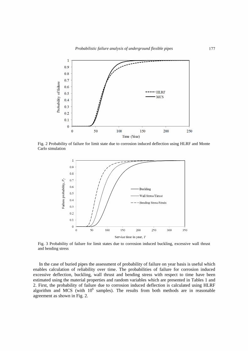
Fig. 2 Probability of failure for limit state due to corrosion induced deflection using HLRF and Monte
Carlo simulation
Fig. 3 Probability of failure for limit states due to corrosion induced buckling, excessive wall thrust
and bending stress
In the case of buried pipes the assessment of probability of failure on year basis is useful which
enables calculation of reliability over time. The probabilities of failure for corrosion induced
excessive deflection, buckling, wall thrust and bending stress with respect to time have been
estimated using the material properties and random variables which are presented in Tables 1 and
2. First, the probability of failure due to corrosion induced deflection is calculated using HLRF
algorithm and MCS (with 106 samples). The results from both methods are in reasonable
agreement as shown in Fig. 2.
177

Kong Fah Tee, Lutfor Rahman Khan and Hua-Peng Chen
Fig. 4 Probability of failure for different limit states versus pipe wall thickness
Fig. 5 Probability of failure for different pipe diameters due to corrosion induced buckling
Next, only Monte Carlo simulation is used for estimation of failure probability for ultimate limit
states due to corrosion induced buckling, excessive wall thrust and bending stress. Fig. 3 shows
that excessive bending stress is the most critical failure event whereas buckling has the lowest
probability of failure during the whole service life of the pipe. Considering the failure probability
of 0.1 (10%) as a threshold level for the safe service life (Babu and Srivastava 2010), the study
illustrates that the safe service life in the worst case scenario is less than 50 years.
4.2 Parametric study
To analyse the effect of the design variables on the probability of failure of the underground
flexible pipeline system, a parametric study has been carried out. The effect of changing the wall
thickness, pipe diameter and backfill height on the probability of failure has shown in Figs. 4, 5
and 6, respectively.
178

Probabilistic failure analysis of underground flexible pipes
Fig. 6 Probability of failure for different backfill heights due to corrosion induced excessive wall thrust
4.2.1 Pipe wall thickness The original thickness of the pipe is 21 mm but the range of the x-axis of the Fig. 4 (pipe wall
thickness) is plotted from 16 mm because pipe failure does not commence (probability of failure is
almost equal to zero) in the beginning of the pipe lessening process for all the corrosion induced
failure criteria until the residual thickness reaches 15.5 mm. On the other hands, the pipe totally
fails (probability of failure is almost equal to one) when the residual thickness reaches 12 mm for
all the failure criteria except the failure due to buckling. It is observed that in the case of failure
due to buckling, the result shows that the pipe needs more thickness reduction to fail than others.
In this case, the range is from 14.5 mm to 10.5 mm. Therefore, it can be concluded that buckling is
the least susceptible whereas the excessive bending stress is the most susceptible due to reduction
of the pipe wall thickness.
4.2.2 Pipe diameter The probability of failure has been estimated for pipe diameter of 1.19 m, 1.21 m and 1.23 m
using all the four different failure criteria. However, only result for buckling is shown in this paper
(Figure 5) because it shows the largest effect due to changes in pipe diameter. In fact, the results
show that the larger diameter pipes have a higher failure rate than the smaller ones i.e. the service
life of pipe decreases as pipe diameter increases. The obtained results are in a good agreement with
the results of the previous studies. A number of authors have investigated the relationship between
sewer size and its structural reliability. Involving large sewer samples with length of 180 km,
O‟Reilly et al. (1989) noticed that the incidence of longitudinal cracks increased with diameter and
also observed that fractures were much more common in larger size of pipes. O‟Reilly et al.
(1989) also observed that when all defects were considered, the pipes with middle ranges of
diameters (300 – 700 mm) showed more defects than those with smaller sizes. Larger pipes are
more at risk to structural damage due to their bulk and weight making them more difficult to lie
accurately (Davis et al. 2001). Similarly, this analysis also shows that the highest failure
probability is due to excessive bending stress and the lowest is due to buckling.
4.2.3 Soil height Like pipe diameter, backfill height also affects pipe failure rate. The probability of failure for
179
Kong Fah Tee, Lutfor Rahman Khan and Hua-Peng Chen
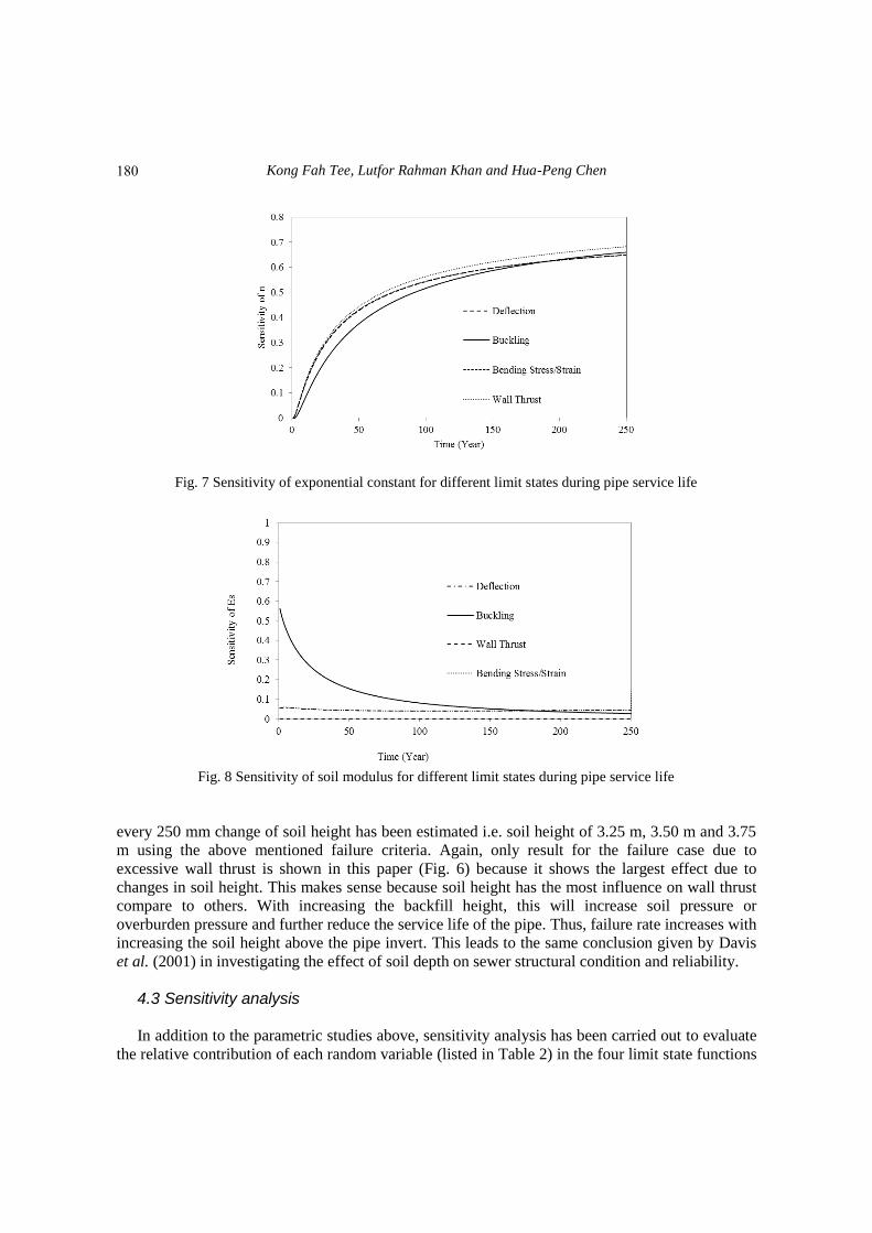
Fig. 7 Sensitivity of exponential constant for different limit states during pipe service life
Fig. 8 Sensitivity of soil modulus for different limit states during pipe service life
every 250 mm change of soil height has been estimated i.e. soil height of 3.25 m, 3.50 m and 3.75
m using the above mentioned failure criteria. Again, only result for the failure case due to
excessive wall thrust is shown in this paper (Fig. 6) because it shows the largest effect due to
changes in soil height. This makes sense because soil height has the most influence on wall thrust
compare to others. With increasing the backfill height, this will increase soil pressure or
overburden pressure and further reduce the service life of the pipe. Thus, failure rate increases with
increasing the soil height above the pipe invert. This leads to the same conclusion given by Davis
et al. (2001) in investigating the effect of soil depth on sewer structural condition and reliability.
4.3 Sensitivity analysis
In addition to the parametric studies above, sensitivity analysis has been carried out to evaluate
the relative contribution of each random variable (listed in Table 2) in the four limit state functions
180

Probabilistic failure analysis of underground flexible pipes
Fig. 9 Sensitivity of backfill height for different limit states during pipe service life
using Eq. (24). The analysis shows that soil (backfill) density, soil modulus, wheel load,
multiplying constant, exponential constant and pipe thickness are among larger contributors and
on the other hand, elastic modulus of pipe material, deflection coefficient and soil height above
pipe invert have minor contribution to the pipe reliability. Selected results are shown in this paper
due to space limitations that are exponential constant in Fig. 7, soil modulus in Fig. 8 and soil
height in Fig. 9.
At the early stage of the pipe service life, the sensitivity of the exponential constant in Eq. (1)
has zero impact and increases significantly with the pipe age for all the four failure criteria as
shown in Fig. 7. This is attributed to the fact that corrosion does not cause any problem to new
pipes but mainly the root cause of failure and collapse for aging pipes. The sensitivity analysis also
shows that soil modulus has zero impact on the failure due to excessive wall thrust as shown in
Figure 8 because it does not appear in Eqs. (9) and (10). In contrast, Fig. 9 shows that backfill
height has the largest impact as predicted in the previous parametric study, although it only has
minor contribution compare to other random variables.
5. Conclusions
A failure probability analysis of underground flexible pipeline has been presented in this paper
using HLRF algorithm and Monte Carlo simulation. The behaviour of buried pipes is considerably
influenced by uncertainties due to external loads, corrosion parameters, pipe materials and
surrounding soil properties etc. The dominating failure criteria of flexible pipes are characterized
by corrosion induced excessive deflection, buckling, excessive wall thrust and bending stress. The
results show that excessive bending stress is the most critical failure event whereas buckling is the
least susceptible during the whole service life of the pipe. In addition, parametric study and
sensitivity analysis have been performed to analyse the effect of the design variables on the
probability of failure of the underground flexible pipeline system. The proposed work is studied
with independent failure events. More complicated and correlation between the failure events and
random variables will be considered in the future work. The estimation of failure probability may
181
Kong Fah Tee, Lutfor Rahman Khan and Hua-Peng Chen
then be utilized to predict the maintenance and repair options during expected service life time and
hence, a renewal strategy can be applied to avoid unexpected collapse or failure of the pipe
network.
Rererences
Ahammed, M. and Melchers, R.E. (1994), “Reliability of underground pipelines subject to corrosion”,
Journal of Transportation Engineering, ASCE, 120(6), 989-1002.
Ahammed, M. and Melchers, R.E. (1997), “Probabilistic analysis of underground pipelines subject
tocombined stresses and corrosion”, Engineering Structures, 19(12), 988-994.
ASCE (American Society of Civil Engineers) (2001), „Guidelines for the design of buried steel pipe‟,
American Lifelines Alliance, USA.
AWWA (American Water Works Association) (1999), „Fiberglass Pipe Design‟, AWWA Manual M45,
USA, 35-53.
ASCE (American Society of Civil Engineers) (2001), „Guidelines for the design of buried steel pipe‟,
American Lifeline Alliance and ASCE, USA, 9-20.
Babu, S.G.L. and Srivastava, A. (2010), “Reliability analysis of buried flexible pipe-soil systems”, Journal
of Pipeline Systems Engineering and Practice, ASCE, 1(1), 33-41.
Babu, S.G.L., Srinivasa, M.B.R. and Rao, R.S. (2006), “Reliability analysis of deflection of buried flexible
pipes”, Journal of Transport Engineering, 132(10), 829-836.
Barbosa, M.R., Morris, D.V. and Sarma, S.V. (1989), “Factor of safety and probability of failure of rockfill
embankments”, Geotechnique, 39(3), 471-483.
Berti, D., Stutzman, R., Lindquist, E. and Eshghipour, M. (1998), “Technical forum: buckling of steel tunnel
liner under external pressure”, J. Energy Eng., 124(3), 55-89.
BS EN 1295:1 (1997), „Structural design of buried pipelines under various conditions of loading- General
requirements‟, British Standards Institution, UK.
BS 9295 (2010), „Guide to the structural design of buried pipelines‟, British Standards Institution, UK.
Baecher, G.B. and Christian, J.T. (2003), Reliability and statistics in geotechnical engineering, Wiley, New
York, USA.
Chughtai, F. and Zayed, T. (2008), „”Infrastructure condition prediction models for sustainable sewer
pipelines”, Journal of Performance of Constructed Facilities, 22(5), 333-341.
CPSA (Concrete Pipeline Systems Association) (2008), Charles Street, Leicester, UK
Farshad, M. (2006), Plastic Pipe Systems: Failure Investigation and Diagnosis, First Edition. Elsevier Ltd.
Gabriel, L.H. (2011), “Corrugated polyethylene pipe design manual and installation guide”, Plastic Pipe
Institute, USA.
Haldar, A. and Mahadevan, S. (2000), Reliability Assessment Using Stochastic Finite Element Analysis,
Chapter 3: Fundamentals of reliability analysis, Wiley and Sons, Canada.
Hasofer, A.M. and Lind, N.C. (1974), “An exact and invariant first order reliability format”, Journal of
Engineering Mechanics Division, ASCE, 100(12), 111-121.
Hauch, S. and Bai, Y. (1999), “Bending moment capacity of pipes”, Proc. of the 18th
International
Conference on Offshore Mechanics and Arctic Engineering, Newfoundland, Canada, July.
Lee, O.S. and Kim, D.H. (2006), “Reliability of buried pipelines with corrosion defects under varying
boundary conditions”, Journal of Solid State Phenomena, 110,183-192.
O‟Reilly, M.P., Rosbrook, R.B., Cox, F.C. and McCloskey, A. (1989), “Analysis of defects in 180km of
pipe sewers in southern water authority”, TRRL Research report 172.
Rackwitz, R. and Fiessler, B. (1978), “Structural reliability under combined random load sequences”,
Computers & Structures, 9(5), 489-494.
Rajani, B. and Makar, J. (2000), “A methodology to estimate remaining service life of grey cast iron water
mains”, Journal of Civil Eng. National Research Council of Canada, 27, 1259-1272.
182
Probabilistic failure analysis of underground flexible pipes
Sarplast: IniziativeIndustriali S.P.A. (2008), “Installation Manual”, 19-23, Santa Luce, Italy.
Sadiq, R., Rajani, B. and Kleiner, Y. (2004), “Probabilistic risk analysis of corrosion associated failures in
cast iron water mains”, Reliability Engineering and System Safety, 86(1), 1-10.
Tee, K.F. and Li, C.Q. (2011), “A numerical study of maintenance strategy for concrete structures in marine
environment”, Proc. of the 11th
International Conference on Applications of Statistics and Probability in
Civil Engineering, Zurich, Switzerland, August.
Tee, K.F., Li, C.Q. and Mahmoodian, M. (2011), “Prediction of time-variant probability of failure for
concrete sewer pipes”, Proc. of the 12th International Conference on Durability of Building Materials and
Components, Porto, Portugal.
Watkins, R.K. and Anderson, L.R. (2000), Structural Mechanics of buried pipes, CRC Press, LLC,
Washington, D.C.USA.
183