PRO8000 Series Mainframes Operation Manual
61
Thorlabs Instrumentation PRO8000 Series Mainframes Operation Manual 2021
Transcript of PRO8000 Series Mainframes Operation Manual

Thorlabs Instrumentation
PRO8000 Series MainframesOperation Manual
2021

Copyright © 2021 Thorlabs GmbH
Version:Date:
Item No.:
3.707-Jun-2021
M0009-510-210
Foreword
Contents4
1 General Information 5
51.1 Safety
61.2 Ordering Codes and Accessories
2 Getting Started 8
82.1 Parts List
82.2 Operating Elements
112.3 First Steps
3 Operating Instruction 12
123.1 After Power-On
123.2 Main Menu
123.3 The Cursor
133.4 Selecting a Module
133.5 Setup Menu
4 Communication With a PC 14
144.1 Hardware Standard RS232C
164.1.1 Interface Specification
164.1.2 Emulating The IEEE488 Bus Commands
174.1.3 Service Request Emulation
174.1.4 Operating Commands
184.2 Hardware Standard IEEE 488.1
184.2.1 IEEE 488.1 Subsets Of The PRO8000 Series
184.2.2 Device Address and String Terminator
194.2.3 Starting The IEEE488 Interface
194.2.4 IEEE488 Bus Commands
214.3 Software Standard IEEE488.2
214.3.1 Nomenclature
214.3.2 Program and Response Messages
214.3.3 Data Format
224.3.4 Commond Commands and Queries
244.3.5 Module Specific Commands and Queries
254.4 Error Messages
254.4.1 Empty Error Queue
254.4.2 100 ... 199 Command Error Messages
264.4.3 200 ... 299 Execution Error Messages
264.4.4 300 ... 399 System Error Messages
274.4.5 400 ... 499 Query Error Messages
274.5 Status Reporting

304.5.1 Standard Event Status Register (ESR)
304.5.2 Standard Event Status Enable Register (ESE)
304.5.3 Status Byte Register (STB)
314.5.4 Service Request Enable Register (SRE)
314.5.5 Device Error Summary Register (DESR)
314.5.6 Device Error Summary Enable Register (DESE)
314.5.7 Device Error Condition Register (DEC)
324.5.8 Device Error Event Register (DEE)
324.5.9 Device Error Event Enable Register (EDE)
324.5.10 Block Function Condition Register (BFC)
324.5.11 Block Function Event Register (BFR)
324.5.12 Block Function Enable Register (BFE)
324.5.13 Service Request by Detecting SRQ
324.5.14 Service Request by *STB? Command
334.5.15 Hints for Setting Up Control Programs
344.6 System Reset
344.6.1 Power-On Reset
344.6.2 Reset by Device Clear
354.6.3 Reset by the Clear Status Command
354.6.4 Reset by the Reset Command
354.6.5 Reset by Interface Clear
364.7 The PRO8000 Series "ELCH" Macro Functions
364.7.1 What Is ELCH ?
364.7.2 Basic Settings
364.7.3 Individual Settings for a Measurement
364.7.3.1 Start and Stop Values for the Chosen Parameter
374.7.3.2 Number of Steps for the Chosen Interval
374.7.3.3 Number of Measured Values for Every Step
374.7.4 Cascading Several ELCH Runs
394.7.5 Values to be Measured
404.7.6 Setting the Desired Measurement Mode
404.7.7 Reading the ELCH Status
414.7.8 Reading the Measured Values
424.7.9 Example of an ELCH Measurement Procedure
434.7.10 Possible ELCH Error Sources
5 Maintenance and Service 44
445.1 Installing and Uninstalling Modules
455.2 Exchanging the Mains Fuse
465.3 Changing the Line Voltage Setting
475.4 Replacement of Internal Fuses
485.5 Troubleshooting
6 Appendix 50

506.1 Technical Data
516.2 Certifications and Compliances
526.3 Letter of Volatility
526.4 Literature
536.5 Warranty
546.6 Copyright and Exclusion of Liability
556.7 Thorlabs 'End of Life' Policy
566.8 List of Acronyms
586.9 Thorlabs Worldwide Contacts

© 2021 Thorlabs GmbH
We aim to develop and produce the best solution for your applicationin the field of optical measurement technique. To help us to live up toyour expectations and improve our products permanently we needyour ideas and suggestions. Therefore, please let us know aboutpossible criticism or ideas. We and our international partners arelooking forward to hearing from you.
In the displays shown by the PRO8 you may find the name PROFILE. PROFILE was the name of the manufacturer before it was acquiredby Thorlabs and renamed to Thorlabs.
Thorlabs GmbH
Warning
Sections marked by this symbol explain dangers that might result inpersonal injury or death. Always read the associated informationcarefully, before performing the indicated procedure.
Please read these advices carefully!
This manual also contains "NOTES" and "HINTS" written in this form.
Attention
Paragraphs preceeded by this symbol explain hazards that coulddamage the instrument and the connected equipment or may causeloss of data.
Note
4

© 2021 Thorlabs GmbH
1 General Information
5
1 General InformationThis part of the instruction manual contains specific information on how to operate the modularPRO8000 Series mainframe.
The descriptions of the modules are given in the individual module manuals.
The units of the PRO8000 Series are modular platforms for electro-optical test and control ap-plications.
The high channel count and the wide variety of plug-in modules allow complex systems andsolutions with a small footprint.
With the comfortable manual operation and the built-in RS232 and IEEE488.2 interfaces, thePRO8000 Series is the right choice for lab applications as well as for remote controlled test sys-tems.
1.1 Safety
Attention
All statements regarding safety of operation and technical data in this instruction manual willonly apply when the unit is operated correctly as it was designed for.
Prior to applying power to the PRO8000 Series, make sure that the protective conductor of themains power cord is correctly connected to the protective earth ground contact of the socketoutlet! Improper grounding can cause electric shock resulting in damage to your health or evendeath!
Also make sure that your line voltage agrees with the voltage given on the letterplate of the unitand that the right fuse has been inserted!
To avoid damage to the modules used or to the mainframe, modules must not be installed orremoved when the mainframe is switched on.
All modules must be fixed using the screws provided for this purpose.
The PRO8000 Series must not be operated in explosion endangered environments!
Do not remove covers! Do not obstruct the air ventilation slots in the housing!
Refer servicing to qualified personnel!
Only with written consent from Thorlabs may changes to single components be made or com-ponents not supplied by Thorlabs be used.
This precision device is only serviceable if properly packed into the complete original pack-aging. If necessary, ask for a replacement package prior to return.
All connections to the load must be made using shielded cables, unless otherwise stated.
The PRO8000 Series laser modules can deliver up to several 100mW of possibly invisible laserradiation! Improper operation can cause severe eye and health damage!
Pay strict attention to the safety recommendations of the appropriate laser safety class! Thelaser safety class is marked on PRO8000 Series laser source module.
Attention
The following statement applies to the products covered in this manual, unless otherwise spe-cified herein. The statement for other products will appear in the accompanying documentation.
This equipment has been tested and found to comply with the limits for a Class A digital device,pursuant to part 15 of the FCC Rules. These limits are designed to provide reasonable protec-tion against harmful interference when the equipment is operated in a commercial environment.This equipment generates, uses, and can radiate radio frequency energy and, if not installed

© 2021 Thorlabs GmbH6
PRO8000 Series
and used in accordance with the instruction manual, may cause harmful interference to radiocommunications. Operation of this equipment in a residential area is likely to cause harmful in-terference in which case the user will be required to correct the interference at his own ex-pense.
Thorlabs is not responsible for any radio television interference caused by modifications of thisequipment or the substitution or attachment of connecting cables and equipment other thanthose specified by Thorlabs. The correction of interference caused by such unauthorized modi-fication, substitution or attachment will be the responsibility of the user.
The use of shielded I/O cables is required when connecting this equipment to any and all op-tional peripheral or host devices. Failure to do so may violate FCC and ICES rules.
Attention
Mobile telephones, cellular phones or other radio transmitters are not to be used within therange of three meters of this unit since the electromagnetic field intensity may then exceed themaximum allowed disturbance values according to IEC 61326-1.
This product has been tested and found to comply with the limits according to IEC 61326-1 forusing connection cables shorter than 3 meters (9.8 feet).
Attention
Mounting several PRO8000 (-4) in a rack, make sure to have 1 height-unit space between thedifferent housings to ensure proper ventilation (ventilation slots are beneath the front panel!)
Use only the supplied mains cord with safety mains plug to connect the unit to the mains! Theunit is grounded via the protective conductor of this cable. To avoid electric shocks the plug ofthe mains cable must be inserted in a correctly grounded socket.
Interruption of the protective grounding could lead to health damage or even death due to elec-tric shock.
Please check prior to operation, if the line voltage indicated on the rear panel agrees with yourlocal supply. If not please have a service technician change the line voltage and the appropriatefuse.
Attention
Changing the line voltage is a service operation and must be done only by qualified service per-sonnel! (see section Changing the Line Voltage Setting ).
Attention
Do not open the unit during operation. Internal adjustments as well as replacement of parts isonly to be done by especially trained service personnel. Parts must not be exchanged while theunit is switched on. Dangerous voltages may also be present in the unit when switched off andwith power cord removed.
Proper discharge of power components is advised.
1.2 Ordering Codes and Accessories
Please refer to the actual catalog or the web for an actual list of available plug in modules andaccessories and for the complete ordering codes.
Ordering-code Short description
Mainframes
PRO800 Mainframe for up to 2 modules, up to 4 A per slot
PRO8000 Mainframe for up to 8 modules, up to 4 A per slot
46

© 2021 Thorlabs GmbH
1 General Information
7
PRO8000-4 Mainframe for up to 8 modules, up to 4 A per slot
Modules for the PRO8 series:
LDC8xxx Laser diode controllers, 7 types, 100 mA to 8 A f.s.
MLC8xxx 8 channel Laser diode controllers, 8 types, 25 mA to 200 mA f.s.
TED8xxx Temperature controllers, 3 types, 2 A to 8 A f.s.
ITC8xxx Laser diode and temperature controllers, 3 types, 200 mA to 1 A f.s. lasercurrent, 2 A TEC current
PDA8000 Photo diode current meter, 1 or 2 channel, 7 ranges, 10 nA to 10 mA f.s.
WDM8xxx Laser modules in the ITU grid, C and L- band
OSW8xxx Optical switches for the 1310 / 1550 nm range, 1x2 to 1x8, 2x2
Shielded cable:
CAB400 Cable to connect an LDC8xxx to a laser diode mount
CAB420-15 Cable to connect a TED8xxx to a laser diode mount
CAB430 Cable to connect an ITC8xxxDS15 to a laser diode mount

© 2021 Thorlabs GmbH8
PRO8000 Series
2 Getting Started
2.1 Parts List
Inspect the shipping container for damage.
If the shipping container seems to be damaged, keep it until you have inspected the contentsand you have inspected the PRO8000 Series mechanically and electrically.
Verify that you have received the following items within the package:
1. PRO800 or PRO8000 or PRO8000-4
2. Power cord, connector according to ordering country
3. Operation Manual
4. CD with drivers and software
5. Inserted modules as ordered with the mainframe
6. Blind plates in the empty slots
2.2 Operating Elements
Front Panel

© 2021 Thorlabs GmbH
2 Getting Started
9
1 Module slots. The PRO8000 and PRO8000-4 can house up to 8 plug-in modules, thePRO800 two modules. All in- or outputs are accessible directly at the front of themodules.
2 The alphanumeric vacuum-fluorescence display enables interactive communicationwith the PRO8000 Series. Different menus allow a clearly structured representation ofthe relevant values.
3 LOCAL key - switches to manual operation from remote control. The LED lights if inlocal mode. If a remote controller has given a “local lock-out” command [LLO], thiskey is disabled for further operation until you switch off the unit or give the command[GTL].
4 Escape key - interrupts the actual procedure
5 ON/OFF key - switches a module / a channel on or off
6 Channel key - selects a module / a channel
7 Tuning knob - allows to change numerical values can be changed. The respectivevalue is selected with the cursor (}) and to value to be changed.
Example: } 1550.83
8 Three blue soft keys have different functions in the different menus. The respectivefunction is shown in the bottom line of the display.
9 The mains switch is a key-operated power control switch (ON / STANDBY) to preventaccidental or non-authorized use.

© 2021 Thorlabs GmbH10
PRO8000 Series
Rear Panel
1 IEEE488 interface connector
2 Two-pin DIP switch. For Service Only! For normal operation, both switches must be inposition "right".
3 Trigger Input
4 Trigger Output
5 GROUND connector (4 mm banana jack)
6 RS232 interface connector
7 Mains connector with fuse holder
8 Fuse list with a marker, indicating the line voltage setting
9 Fans and air outlet
Notes
1. The DIP switches (2) must be set to the right position for normal operation of the PRO8000Series.
2. The screw on the fuse list is just a marker that indicates the line voltage setting. See section Changing Line Voltage Setting for instructions.46

© 2021 Thorlabs GmbH
2 Getting Started
11
2.3 First Steps
Prior to starting operation of the PRO8000 Series, check if the line voltage specified on the let-ter plate agrees with your local supply and if the appropriate fuse is inserted. To change the linevoltage see Changing Line Voltage Setting .
Connect the unit to the line with the provided mains cable. Turn the unit on by means of themains switch.
The 4mm banana jack allows to connect the chassis ground to the ground of the externalsetup.
The display lights up several seconds after switching on the unit. The system boot process maytake around 15 sec. If no display is shown after this time, please check line voltage and linefuse.
The PRO8000 Series mainframe is ready to use immediately after turning on. However, awarm-up time is required in order to reach the specified accuracy of the plugged-in modules.Please refer to the manuals of the installed modules for closer information.
46

© 2021 Thorlabs GmbH12
PRO8000 Series
3 Operating Instruction
3.1 After Power-On
After turning on your PRO8000 Series the main processor executes a self test program for sev-eral seconds.
THORLABS PRO8000
Power On Self Test
SW Revision 4.65
Interface 1.31
The display shows the actual software and interface revision number. After a few seconds theprogram enters the main menu screen.
3.2 Main Menu
PRO8000 Series Main Menu with WDM Laser Sources
The first three lines show the contents of the respective menu. In this example "Main Menu" thewavelengths of the inserted WDM modules of the channels CH1 to CH3 are displayed.
The fourth line describes the functions of the three soft keys (here up (é), down (ê) andTUNE).
3.3 The Cursor
The cursor of the display can be placed at different positions in the display. It can point to val-ues to the left (|) or to the right (}).
The cursor can be moved up with the soft key • or down with the soft key � .
With the cursor leaving the upper or lower edge of the display you can scroll through the wholecontent of the corresponding screen.
With the cursor in the third line, the next line will appear from below when pressing � .
Example in the main menu with 8 lines for the channels:

© 2021 Thorlabs GmbH
3 Operating Instruction
13
Channels 1 and 2
CH3 1549.31 offCH4|1550.92 offCH5 1552.52 off
Channels 6 to 8
3.4 Selecting a Module
A module is selected for further input by placing the cursor beside the respective channel num-ber.
CH4|
Pressing will lead to the channel menu of the selected module. Please refer to the opera-tion manual of the individual module.
3.5 Setup Menu
The Setup Menu can be entered from the main menu by pressing :
PRO8000 SETUP? Beeper : onInterface: IEEE488IEEE Adr : 10Baudrate : 19200OSR local 1024 CHANGE
In above sample the first line "Beeper" is marked by the cursor, so pushing the “CHANGE” but-ton toggles the beeper (signal for occurring errors and input confirmation) on and off.
The second line allows to select the IEEE488 Interface the terminal mode via RS232 Interface.
In the third line the IEEE-address can be set, default value is 10.
The appropriate baud rate for the RS 232 interface can be selected in line 4 (default = 19200Baud).
OSR local allows to select the averaging rate for displayed values, i.e. how many measuredvalues are averaged to reduce noise. The higher the value, the longer it takes to actualize themeasured values on the screen. This item does not affect the remotely transferred measure-ment values. (‘Normal’ value =16).
Pushing again brings you back to main menu.
© 2021 Thorlabs GmbH14
PRO8000 Series
4 Communication With a PC
Note
When remote control is active, the following operating elements are still enabled:
· The "Go To Local" key
· the LEDs SEL, ERR and ON and all potentiometers on the installed modules
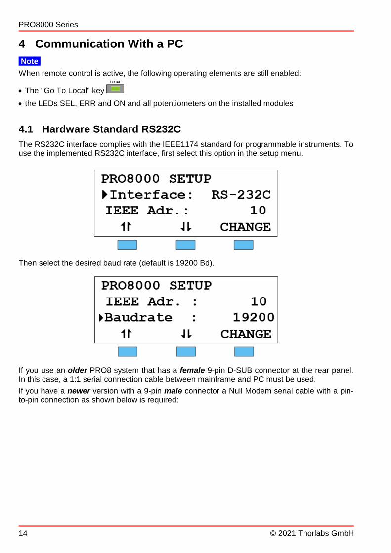
4.1 Hardware Standard RS232C
The RS232C interface complies with the IEEE1174 standard for programmable instruments. Touse the implemented RS232C interface, first select this option in the setup menu.
Then select the desired baud rate (default is 19200 Bd).
If you use an older PRO8 system that has a female 9-pin D-SUB connector at the rear panel.In this case, a 1:1 serial connection cable between mainframe and PC must be used.
If you have a newer version with a 9-pin male connector a Null Modem serial cable with a pin-to-pin connection as shown below is required:

© 2021 Thorlabs GmbH
4 Communication With a PC
15
If your control PC does not support DSR/DTR signaling the connections of the Null Modemcable must be modified as shown below:

© 2021 Thorlabs GmbH16
PRO8000 Series
4.1.1 Interface Specification
Electrical characteristics EIA RS232C
Connector 9pin D-SUB (male)
Communication Full duplex
Baud rate 1200, 2400, 4800, 9600, 19200, 38400
Start bit 1 bit
Stop bit 1 bit
Data length 8 bit
Parity No parity
Handshaking RTS / CTS
Receive buffer length 256 bytes
Termination character CR LF (ASCII 0DH0AH)
4.1.2 Emulating The IEEE488 Bus Commands
As the RS232 interface does not offer hardware control lines like the IEEE488 bus, the accord-ing IEEE488 bus command are emulated by specials commands.
(Please refer to chapter Hardware Standard IEEE 488.1 )
Device CLear
Syntax: "&DCL"
Description: Clears the input buffer and output queue. Resets the parser unit and the execu-tion unit
Go To Local
Syntax: ">L"
Description: Switches the PRO8000 into LOCAL mode (manual operation). Previously setvalues for laser current, laser power, temperature etc. remain valid.
Local LockOut
Syntax: "&LLO"
Description: Disables the button. Return to LOCAL mode (manual operation) is only
possible with the command ">L".
Poll Status-byte
Syntax: "&POL"Description: Reads the status byte and clears bit 6 (MSS). This command is used to emulate
a service request.
18

© 2021 Thorlabs GmbH
4 Communication With a PC
17
4.1.3 Service Request Emulation
To get the instrument status byte asynchronously, the service request sequence is used:
· In case the device needs a service request it sends [&SRQ] to the PC.
· Now the PC should query the status byte with "&POL".
· The device will then answer with [&nnn] where nnn represents the status byte in decimalnotation.
See chapter Service Request Enable Register (SRE)
4.1.4 Operating Commands
For the RS232C communication, all operating commands as described in the followingIEEE488 section and in the individual module manuals are valid.
31

© 2021 Thorlabs GmbH18
PRO8000 Series
4.2 Hardware Standard IEEE 488.1
The IEEE488 interface of the PRO8000 Series is based on the IEEE 488.2 standard. This in-cludes the IEEE 488.1 standard for the hardware settings. There is a standard 24-pin IEEE488jack on the rear panel. The address of the PRO8000 Series mainframe must differ from that ofother devices using the same IEEE488 bus.
You can select it in the setup menu , see section Setup Menu .
4.2.1 IEEE 488.1 Subsets Of The PRO8000 Series
Function Part set
Source Handshake SH1
Acceptor Handshake AH1
Talker T6
Listener L4
Service Request SR1
Remote/Local RL1
Parallel Poll PP0
Device Clear DC1
Device Trigger DT0
Electrical Interface E1
4.2.2 Device Address and String Terminator
Address
The device address of the PRO8000 Series can be changed by pressing in the mainmenu. The display shows:
Pressing the key (CHANGE), soft keys ¬ ..... ® appear, enabling the address to be changed.The device address can be selected between 0 and 30.
Pressing saves the new setting and return to the main screen.
Note
The default device address is 10.
13

© 2021 Thorlabs GmbH
4 Communication With a PC
19
String terminator
The string terminator of the PRO8000 Series is preset to <LF><EOI>. This is fixed and cannotbe changed. The PRO8000 Series accepts any combination of <LF> and <EOI> as string ter-minator.
4.2.3 Starting The IEEE488 Interface
· Connect the PRO8000 Series and the PC with shielded IEEE488 cables
· Connect the units to the mains
· Switch on both units
In order to ensure a safe data transmission, the length of the IEEE488 cable between two unitsshould not exceed 2 meters and the total cable length of the IEEE488 bus should not exceed20 meters.
The PRO8000 Series will automatically enter the REMOTE mode when the first command is re-ceived from the PC.
Note
Programming of the control software will vary with the type of computer, the user interface, theprogramming language, the interface card used as well as with the driver software and the cor-respondingly supplied software interfaces. Please refer to the documentation of these compon-ents.
Also, please refer to section Hints for Setting Up Control Programs .
4.2.4 IEEE488 Bus Commands
To communicate via the IEEE488 bus the standard control signals [MLA], [MTA], [UNL], [UNT],[ATN], [REN], [SPE], [SPD] are used.
If the control program for the PRO8000 Series system is written in a language as e.g. BASIC,then these IEEE488 control signals are automatically transmitted to the mainframe according tothe used driver software and do not have to be explicitly produced in the control program.
These functions are already implemented in the Thorlabs LabView® or LabWindows® drivers.
When receiving the IEEE488 bus commands [GET], [LLO], [GTL], [DCL] and [SDC], thePRO8000 Series will execute the following functions:
[LLO] Local LockOut
The command [LLO] once sent will disable the key throughout further operation. A returnto the LOCAL mode (manual operation) is possible only with the command [GTL] (see be-low).
[GTL] Go To Local
The command [GTL] returns the PRO8000 Series to LOCAL mode (manual operation). Val-ues, previously set for laser current, laser power, temperature etc., remain valid.
[DCL] Device Clear
The command [DCL] clears the output queue, the error queue and resets the registers. It af-
fects only the IEEE488 bus electronic (see System Reset ).
Normal operation of the modules is not interrupted.
33
34

© 2021 Thorlabs GmbH20
PRO8000 Series
Note
The command [DCL] resets all IEEE488 units connected to the bus.
[SDC] Selected Device Clear
The command [SDC] resembles the command [DCL] but refers only to the IEEE488 part
of the selected unit (see System Reset ).
Normal operation of the unit is not interrupted.
Note
In contrast to the command [DCL], the command [SDC] resets only the IEEE488 of the ad-dressed device.
[GET] Group Execution Trigger
Due to the interface specification “DT0” (see section IEEE 488.1 Subsets Of The PRO8000Series ), the command [GET] is not implemented.
34
18
© 2021 Thorlabs GmbH
4 Communication With a PC
21
4.3 Software Standard IEEE488.2
4.3.1 Nomenclature
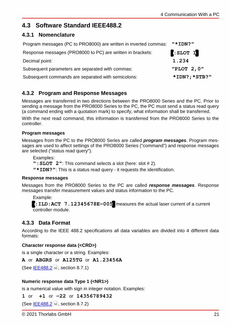
Program messages (PC to PRO8000) are written in inverted commas: "*IDN?"
Response messages (PRO8000 to PC) are written in brackets: [:SLOT 1]
Decimal point: 1.234
Subsequent parameters are separated with commas: "PLOT 2,0"
Subsequent commands are separated with semicolons: *IDN?;*STB?"
4.3.2 Program and Response Messages
Messages are transferred in two directions between the PRO8000 Series and the PC. Prior tosending a message from the PRO8000 Series to the PC, the PC must send a status read query(a command ending with a quotation mark) to specify, what information shall be transferred.
With the next read command, this information is transferred from the PRO8000 Series to thecontroller.
Program messages
Messages from the PC to the PRO8000 Series are called program messages. Program mes-sages are used to affect settings of the PRO8000 Series ("command") and response messagesare selected ("status read query").
Examples:":SLOT 2": This command selects a slot (here: slot # 2).
"*IDN?": This is a status read query - it requests the identification.
Response messages
Messages from the PRO8000 Series to the PC are called response messages. Responsemessages transfer measurement values and status information to the PC.
Example:
[:ILD:ACT 7.12345678E-005] measures the actual laser current of a currentcontroller module.
4.3.3 Data Format
According to the IEEE 488.2 specifications all data variables are divided into 4 different dataformats:
Character response data (<CRD>)
is a single character or a string. Examples:
A or ABGRS or A125TG or A1.23456A
(See IEE488.2 , section 8.7.1)
Numeric response data Type 1 (<NR1>)
is a numerical value with sign in integer notation. Examples:
1 or +1 or -22 or 14356789432
(See IEE488.2 , section 8.7.2)
52
52

© 2021 Thorlabs GmbH22
PRO8000 Series
Numeric response data Type 2 (<NR2>)
is a numerical value with or without sign in floating point notation without exponent. Examples:
1.1 or +1.1 or -22.1 or 14356.789432
(See IEE488.2 , section 8.7.3)
Numeric response data Type 3 (<NR3>)
is a numerical value with or without sign in floating point notation with exponent with sign .Examples:
1.1E+1 or +1.1E-1 or -22.1E+1 or 143.56789432E+306
(See IEE488.2 , section 8.7.4)
4.3.4 Commond Commands and Queries
The IEEE 488.2 standard requires a set of commands, that every device must support. Thesecommands are called mandatory commands. All commands can be single or "compound" having a tree structure. Those with compounds arecalled compound or group commands.
IEEE 488.2 mandatory commands
CommandExplanation
Response Example
*IDN?
Identification query
[THORLABS PRO8000 Ver.4.64-1.31<LF>]
*RSTResets the PRO8000 Series: All outputs of all modules are switchedoff, all macros are deactivated (not deleted), the unit stays in 'ready'status i.e. bit 0 (FIN) of the status byte register is set. All set paramet-ers (current, power values etc. remain valid!)
*TST?Executes a self test and queries the result
[0<LF>]
*OPC Operation completed active mode started
*OPC?Operation completed query
[1<LF>]
*WAI Waiting until the last operation is completed
*CLSClears all event registers (ESR, DEE1...DEE8) and the error queue.Due to the cleared event registers, also DESR is 0, bit 0 (FIN) of theSTB is set.
*ESE <NR1>Sets the value for the standard event status enable register (ESE)
*ESE?Queries the current value of the standard event status enable register(ESE). The content of the register is not changed.
[<NR1><LF>]
*ESR?Queries the current value of the standard event status register (ESR)and clears it the same time.
[<NR1><LF>]
52
52

© 2021 Thorlabs GmbH
4 Communication With a PC
23
CommandExplanation
Response Example
*SRE <NR1>Sets the value of the service request enable register (SRE)
*SRE?Queries the current value of the service request enable register (SRE)
[<NR1><LF>]
*STB?Queries the value of the status byte register (STB). Bit 6 is reset to 0,the other bits kept unchanged.
[<NR1><LF>]
*SAV 0Immediately saves all set values as default values to be loaded on thenext power up.
Mainframe commands
For special macro commands ELCH, see chapter The PRO8000 Series "ELCH" Macro Func-tions .
Command
ExplanationResponse Example
":CONFIG:PLUG?"Shows the configuration of the plug-in modules, always 16 values, module type and subtype for every slot, e.g.:.[:CONFIG:PLUG 223,0,191,0,247,0,159,0,107,1,243,2,47,0,0,0]
":SLOT <NR1>"Selects a slot for further programming
":SLOT?"Queries the selected slot
[:SLOT <NR1><LF>]
":STAT:xxx?"XXX stands for one of the additional IEEE 488 registers implemented(BFC, BFR, BFE, DESR or DESE) It returns the binary content of theregister
[:STAT:xxx <NR1><LF>]
":STAT:xxx <NR1>"Sets the content of the enable register (BFE, EDE and DESE). Refer tosection Status Reporting .
":PORT?"Queries the chosen port of a multidevice controller as MLC8xxx orPDA8xxxx.
[:PORT <NR1><LF>]
":PORT <NR1>"Selects a port of a multidevice controller as MLC8xxx or PDA8xxx.
":SYST:ERR?"Queries the error queue
[0,"No error"<LF>]
":SYST:ANSW?"Query the answering format of the PRO8.
[:SYST:ANSW FULL]
":SYST:ANSW VALUE" PRO8000 Series will send only the requested parameter without designator. Example: When requesting the slotnumber with ":SLOT?" the mainframe will send only [2<LF>] instead of [:SLOT 2<LF>].This is not compliant to the IEEE 488.2 standard but useful under point of increasing speed.
":SYST:ANSW FULL"PRO8000 Series will stop the function started with ":SYST:ANSW VALUE" and respond again according to theIEEE488.2 standard.
36
27
© 2021 Thorlabs GmbH24
PRO8000 Series
Command
ExplanationResponse Example
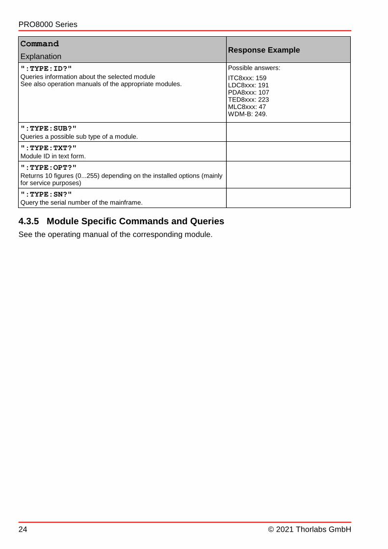
":TYPE:ID?" Queries information about the selected moduleSee also operation manuals of the appropriate modules.
Possible answers:
ITC8xxx: 159LDC8xxx: 191PDA8xxx: 107TED8xxx: 223MLC8xxx: 47WDM-B: 249.
":TYPE:SUB?"Queries a possible sub type of a module.
":TYPE:TXT?"Module ID in text form.
":TYPE:OPT?"Returns 10 figures (0...255) depending on the installed options (mainlyfor service purposes)
":TYPE:SN?"Query the serial number of the mainframe.
4.3.5 Module Specific Commands and Queries
See the operating manual of the corresponding module.

© 2021 Thorlabs GmbH
4 Communication With a PC
25
4.4 Error Messages
Following the IEEE488.2 standard, devices provide an error queue storing errors one by one.Every query ":SYST:ERR?" will fetch one single error from the error queue.
Repeated use of ":SYST:ERR?" is necessary until the error queue is empty.
If the queue is empty, the error message [0, "No error"] is sent to the PC.
Error messages are organized in groups:
Error Number Error Type
0 No Errors
100 ... 199 Command Errors
200 ... 299 Execution Errors
300 ... 399 System Errors
400 ... 499 Query Errors
1000 ... 9999 Module Specific Errors
The module specific error messages are described in the operation manual of the appropriatemodule.
4.4.1 Empty Error Queue
[0,"No errors"]Error queue is empty.
4.4.2 100 ... 199 Command Error Messages
[100,"Unknown command"]Possible reason: The string ":HELLO WORLD". was sent to the mainframe and could not
recognized as valid command.The command ":ILD:SET? 1.1" does not require a numericalparameter.
[101,"Invalid character"]Possible reason: The character Hex 09 sent to the mainframe does not belong to the al-
lowed set of characters.
[102,"Invalid numeric parameter"]Possible reasons: ":ILD:SET 1.1." The second decimal point is not allowed.
":ILD:SET 12E+12E". The second "E" is not allowed.
[103,"Invalid text parameter"]Possible reasons: ":SENSOR CG". This parameter is not valid for a temperature sensor.
":MODE THH". This parameter is not valid for this command.
[104,"Missing parameter"]Possible reason: ":ILD:SET". This command requires a numerical parameter.
[105,"Invalid separator"]Possible reason: ":ILD:SE". This command was not complete.
25
26
26
27
© 2021 Thorlabs GmbH26
PRO8000 Series
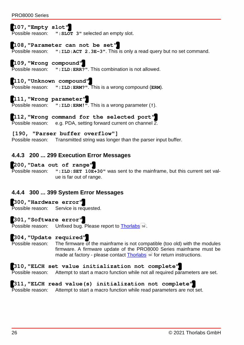
[107,"Empty slot"]Possible reason: ":SLOT 3" selected an empty slot.
[108,"Parameter can not be set"]Possible reason: ":ILD:ACT 2.3E-3". This is only a read query but no set command.
[109,"Wrong compound"]Possible reason: ":ILD:ERR?". This combination is not allowed.
[110,"Unknown compound"]Possible reason: ":ILD:ERM?". This is a wrong compound (ERM).
[111,"Wrong parameter"]Possible reason: ":ILD:ERM!". This is a wrong parameter (!).
[112,"Wrong command for the selected port"]Possible reason: e.g. PDA, setting forward current on channel 2.
[190, "Parser buffer overflow"]Possible reason: Transmitted string was longer than the parser input buffer.
4.4.3 200 ... 299 Execution Error Messages
[200,"Data out of range"]Possible reason: ":ILD:SET 10E+30" was sent to the mainframe, but this current set val-
ue is far out of range.
4.4.4 300 ... 399 System Error Messages
[300,"Hardware error"]Possible reason: Service is requested.
[301,"Software error"]Possible reason: Unfixed bug. Please report to Thorlabs .
[304,"Update required"]Possible reason: The firmware of the mainframe is not compatible (too old) with the modules
firmware. A firmware update of the PRO8000 Series mainframe must bemade at factory - please contact Thorlabs for return instructions.
[310,"ELCH set value initialization not complete"]Possible reason: Attempt to start a macro function while not all required parameters are set.
[311,"ELCH read value(s) initialization not complete"]Possible reason: Attempt to start a macro function while read parameters are not set.
58
58

© 2021 Thorlabs GmbH
4 Communication With a PC
27
4.4.5 400 ... 499 Query Error Messages
[400,"Too many errors"]Possible reason: More than 30 errors in the error queue.
[410,"Query interrupted"]Possible reason: More than one query sent to the mainframe before the read command.
[420,"Query unterminated"]Possible reason: No query sent to the mainframe before the read command.
4.5 Status Reporting
The PRO8000 Series provides nine 8 bit registers to program various service request functions:ESR, ESE, STB, SRE, BFC, BFE, BFR and DESR, DESE
ESR Standard event status register ESE Standard event Status Enable RegisterSTB Status Byte RegisterSRE Service Request Enable RegisterBFC Block Function Condition RegisterBFR Block Function Event RegisterBFE Block Function Enable RegisterDESR Device Error Summary RegisterDESE Device Error Summary Enable Register
(See IEE488.2 , section 4.4) 52

© 2021 Thorlabs GmbH28
PRO8000 Series
Structure of the registers ESR, ESE STB, SRE, BFC, BFR and BFE

© 2021 Thorlabs GmbH
4 Communication With a PC
29
Structure of the registers DESR and DESE, including the device error registers of theplug-in modules.

© 2021 Thorlabs GmbH30
PRO8000 Series
4.5.1 Standard Event Status Register (ESR)
The ESR can be read directly with the command "*ESR?". Reading the ESR clears it at thesame time. The content of the ESR can not be set.
The bits are active high.
Power on
This bit indicates the off to on state of the power supply. State = HIGH after switching on thedevice for the first time.
User request (not used here)
A local control has been activated.
Command error
A command error occurred.
Execution error
An execution error occurred.
Device dependent error
A device dependent error (module error) occurred.
Query error
A error occurred trying to query a value.
Request control
The mainframe is requesting to become the system controller.
Operation complete
All started operations have been completed. System is in idle mode.
4.5.2 Standard Event Status Enable Register (ESE)
The bits of the ESE are used to select which bits of the ESR shall influence bit 5 (ESB) of theStatus Byte Register (STB).
The 8 bits of the ESE are connected by logical "AND" with the according 8 bits of the ESR.These 8 results are connected by logical "OR", so that any "hit" leads to a logical 1 of bit 5(ESB) of the STB.
As any bit of the STB can assert an SRQ, every event (bit of the ESR) can be used to assert anSRQ.
4.5.3 Status Byte Register (STB)
The bits of this register show the status of the PRO8000 Series mainframe. The register can beread out using *STB?. The content of the STB can not be set. The bits are active high.
RQS/MSS
RQS: Request service message: Shows that this device has asserted SRQ.
MSS: Master summary status: Shows that this device requests a service.

© 2021 Thorlabs GmbH
4 Communication With a PC
31
ESB (Event Status Byte)
Shows if any event has occurred in the Standard Event Status Register, enabled by the Stand-ard Event Status Enable Register .
MAV (message available)
This bit is high after a query, as a result "waits" in the output queue to be fetched. It is low, if theoutput queue is empty.
DES (Device Error Summary Register Bit)
Indicates whether any of the plug-in modules has send an error message through its Device Er-ror Event Register.
EAV (Error Available)
Shows the error queue not to be empty yet.
BFR (Block Function Register-Bit)
Indicates whether the block functions are active or the “ELCH” function (ELectrical CHaracteriz-ation) is completed.
FIN (command finished)
This bit is high, after a command has finished and all bits of the STB have been set.
All bits except bit 6 of the STB can be used to assert a service request (SRQ ). Alternatively
the SRQ can be recognized using the command "*STB?" .
4.5.4 Service Request Enable Register (SRE)
The bits of the SRE are used to select, which bits of the STB shall assert an SRQ.
Bit 0, 1, 2, 3, 4, 5 and 7 of the STB are combined by logical "AND" with the according 7 bits ofthe SRE. These 7 results are combined by logical "OR", so that any "hit" leads to a logical 1 inbit 6 of the STB and asserts an SRQ.
4.5.5 Device Error Summary Register (DESR)
Bit 0.....7 indicate if any plug-in module in the slots 1...8 (1..2) has asserted an error messagevia it’s Device Error Event Register .
4.5.6 Device Error Summary Enable Register (DESE)
The DESE enables via “AND” functions which module in which slot is allowed to create an errormessage, i.e. set bit “DES” in the Status Byte Register.
4.5.7 Device Error Condition Register (DEC)
The bits of this register show the errors, that occur during operation (operation errors). The bitsare active high.
The function of the Device Error Condition register depends on the module in the corre-sponding slot. Please refer to the individual operation manual of the plug in module.
30
32
32
29

© 2021 Thorlabs GmbH32
PRO8000 Series
4.5.8 Device Error Event Register (DEE)
The bits of this register hold the errors, that occurred during operation (operation errors). Soeach bits of the DEC sets the according bit of the DEE.
The DEE can be read but not set.
Reading out clears the DEE.
4.5.9 Device Error Event Enable Register (EDE)
The bits of the EDE are used to select, which bits of the DEE shall influence bit 3 (DES) of theSTB.
The 8 bits of the EDE are related by logical "AND" to the according 8 bits of the DEE. These 8results are combined by logical "OR" so that any "hit" leads to a logical 1 in bit 3 (DES) of theSTB.
As any bit of the STB can assert an SRQ, every error (bit of the DEE) can be used to assert anSRQ.
4.5.10 Block Function Condition Register (BFC)
Presently, only bit 0 and 1 of the BFC are functional:
· Bit 0 indicates if the block function mode is active.
· Bit 1 shows if the programmed ELCH function has been completed (= HIGH).
4.5.11 Block Function Event Register (BFR)
The bits of this register hold the status changes that occurred during operation. So each bit ofthe BFC sets the according bit of the BFR.
The BFR can be read but not set.
Reading out clears the BFR.
4.5.12 Block Function Enable Register (BFE)
The BFE enables via “AND” functions which block message is allowed to set the bit “BFR” inthe Status Byte Register.
4.5.13 Service Request by Detecting SRQ
If an SRQ is asserted, bit 6 of the STB is set to logical 1, so that the controller can detect byserial polling, which device asserted the SRQ.
4.5.14 Service Request by *STB? Command
If the controller does not "listen" to SRQs at all, the service request can be detected by readingthe status byte with the command "*STB?".
If bit 6 is logical 1, a service request was asserted.
31

© 2021 Thorlabs GmbH
4 Communication With a PC
33
4.5.15 Hints for Setting Up Control Programs
During the test phase of control programs all program messages should be transmitted separ-ately. Each command should be followed by a status request (response message) so that pos-sible errors are read out directly after the command that might have caused it.
Manufacturers of interface cards that are used in the control computer provide drivers for the bi-directional communication between the PC and the PRO8000 Series mainframe for all commonsoftware packages. We recommend building these write and read back commands into separ-ate functions and then using these functions for the data transfer.
These functions should use an additional global flag that determines whether the write or readback communication is to be stored in a data file together with the talker and listener address ofthe IEEE488 system or printed out additionally. Problems that occurred on the bus or errormessages that cannot be explained immediately can be investigated later by analyzing the datatransfer file between the PRO8000 Series mainframe and the control computer.
The same procedure is useful for the RS 232 communication.

© 2021 Thorlabs GmbH34
PRO8000 Series
4.6 System Reset
There five different types of PRO8000 Series or its installed modules:
· Power-On reset
· Reset by device clear
· Reset by clear status
· Reset by software
· Reset by interface clear
The differences are explained in the subsequent sections.
4.6.1 Power-On Reset
The reset after turning the power on
· sets the power on bit in the Event Status Register (ESR);· deletes the output queue and sets bit 4 (MAV) of the status byte to 0;· clears the error queue is cleared and sets bit 2 (EAV) of the status byte to 0;· clears the execution unit and the command queue;· resets the command decoder (parser);· clears all event registers;· sets the device error summary register to 0;· sets the system to 'ready' state and sets the bit 0 (FIN) of the status byte;· discards all 'ELCH' macro functions;· switches off (disables) the outputs of all installed modules;· resets all set values of the modules to the most recent entered manually resp. to their de-
faults, depending on the module.
4.6.2 Reset by Device Clear
This reset is called by the IEEE bus commands Device CLear [DCL] or Selected Device
Clear [SDC]and it
· deletes the output queue and sets bit 4 (MAV) of the status byte to 0;· clears the error queue is cleared and sets bit 2 (EAV) of the status byte to 0;· clears the execution unit and the command queue;· resets the command decoder (parser);· sets the system to 'ready' state and sets the bit 0 (FIN) of the status byte;· discards all 'ELCH' macro functions;· switches off (disables) the outputs of all installed modules;· resets all set values of the modules to the most recent entered manually resp. to their de-
faults, depending on the module.
All module outputs and set values remain unchanged.

© 2021 Thorlabs GmbH
4 Communication With a PC
35
4.6.3 Reset by the Clear Status Command
The CLear Status command *CLS
· clears the error queue is cleared and sets bit 2 (EAV) of the status byte to 0;· clears all event registers;· sets the device error summary register to 0;· sets the system to 'ready' state and sets the bit 0 (FIN) of the status byte.
4.6.4 Reset by the Reset Command
The Reset command *RST resets all device functions, that is:
· eventually activated macro functions are deactivated (not deleted);· the outputs of all modules are switched off;· system enters the 'Ready' state and bit 0 (FIN) of the status byte is set.
All set values and module assignments remain unchanged.
4.6.5 Reset by Interface Clear
The IFC is a separate line of the IEEE488 bus connection.
The PRO8000 Series is NOT RESPONDING to the activation of this signal line by the controlcomputer.
© 2021 Thorlabs GmbH36
PRO8000 Series
4.7 The PRO8000 Series "ELCH" Macro Functions
4.7.1 What Is ELCH ?
The abbreviation ELCH stands for ELectrical CHaracterization of laser components. ELCH iscomprised of a group of embedded macro functions (block commands) that allow the accelera-tion of standard measurements, for example the LIV curve determination of laser diodes etc.
The advantages of ELCH are a low IEEE488 bus traffic and and increased measurementspeed.
4.7.2 Basic Settings
In order to use the ELCH macro functions, the following basic settings are required:
1. Select the desired module.2. Set the polarities of the laser diode and the monitor diode.3. Set the desired operating mode (constant current or constant power).4. Set the parameters of the temperature controller and switch it on.
4.7.3 Individual Settings for a Measurement
Prior to start a measurement:
1. Define the parameter that shall be changed during measurement (e.g. laser current).
2. Set the start and stop value for this parameter.
3. Set the number of measurement steps within the span between start and stop value.
4. Define how many dependent values (parameters) shall be measured at every single step?
5. Define the mode (continuous or triggered) the ELCH should run.
6. Define which parameter from which module shall be read out.
7. Define the sequence of the parameter values in the answer string.
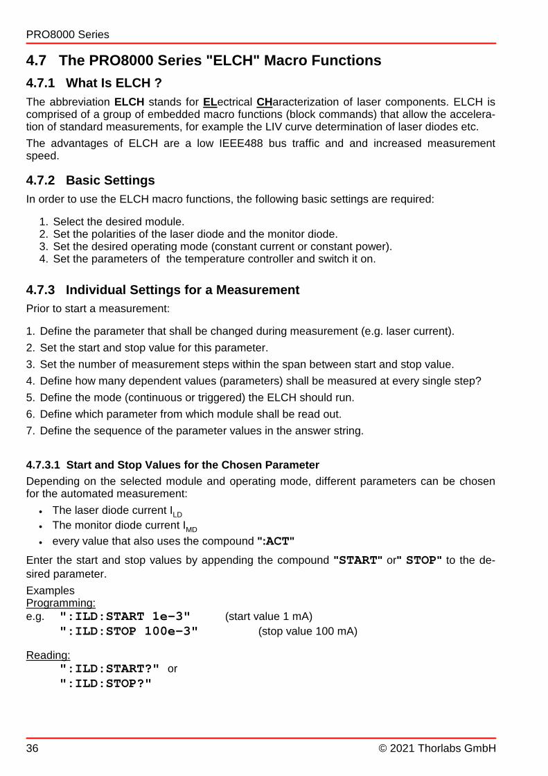
4.7.3.1 Start and Stop Values for the Chosen Parameter
Depending on the selected module and operating mode, different parameters can be chosenfor the automated measurement:
· The laser diode current ILD
· The monitor diode current IMD
· every value that also uses the compound ":ACT"
Enter the start and stop values by appending the compound "START" or" STOP" to the de-sired parameter.
ExamplesProgramming:e.g. ":ILD:START 1e-3" (start value 1 mA)
":ILD:STOP 100e-3" (stop value 100 mA)
Reading:":ILD:START?" or
":ILD:STOP?"
© 2021 Thorlabs GmbH
4 Communication With a PC
37
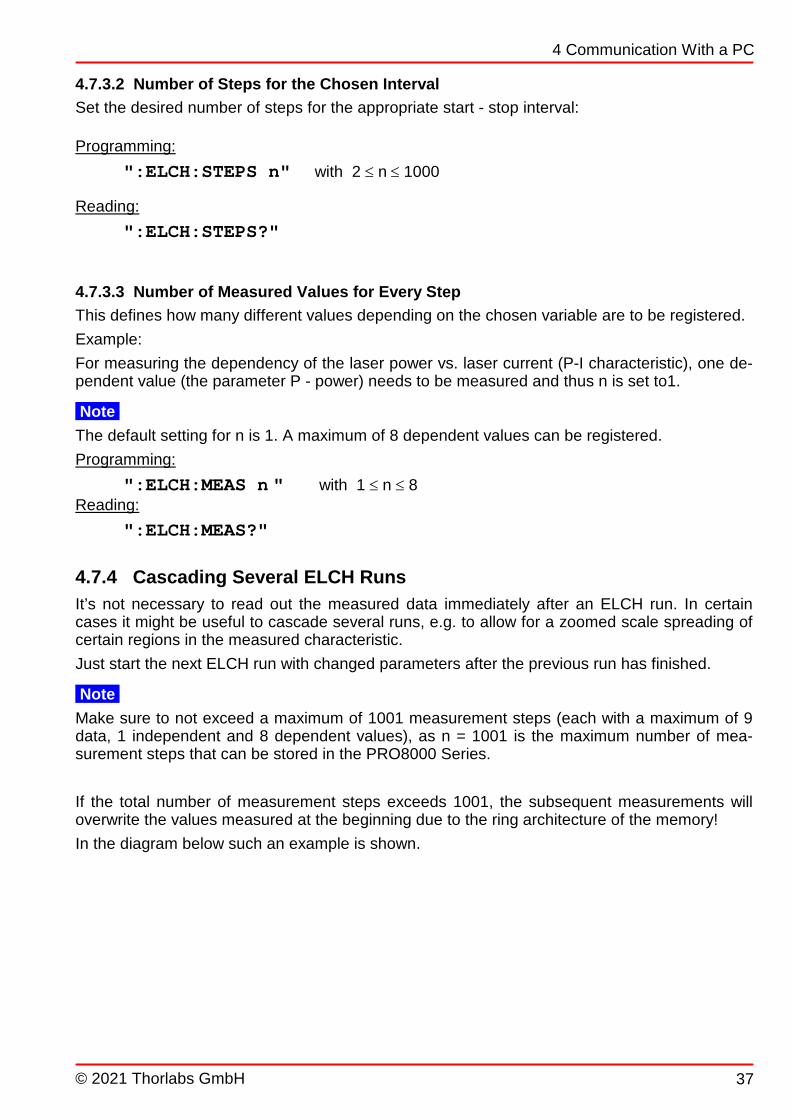
4.7.3.2 Number of Steps for the Chosen Interval
Set the desired number of steps for the appropriate start - stop interval:
Programming:
":ELCH:STEPS n" with 2 £ n £ 1000
Reading:
":ELCH:STEPS?"
4.7.3.3 Number of Measured Values for Every Step
This defines how many different values depending on the chosen variable are to be registered.
Example:
For measuring the dependency of the laser power vs. laser current (P-I characteristic), one de-pendent value (the parameter P - power) needs to be measured and thus n is set to1.
Note
The default setting for n is 1. A maximum of 8 dependent values can be registered.
Programming:
":ELCH:MEAS n " with 1 £ n £ 8Reading:
":ELCH:MEAS?"
4.7.4 Cascading Several ELCH Runs
It’s not necessary to read out the measured data immediately after an ELCH run. In certaincases it might be useful to cascade several runs, e.g. to allow for a zoomed scale spreading ofcertain regions in the measured characteristic.
Just start the next ELCH run with changed parameters after the previous run has finished.
Note
Make sure to not exceed a maximum of 1001 measurement steps (each with a maximum of 9data, 1 independent and 8 dependent values), as n = 1001 is the maximum number of mea-surement steps that can be stored in the PRO8000 Series.
If the total number of measurement steps exceeds 1001, the subsequent measurements willoverwrite the values measured at the beginning due to the ring architecture of the memory!
In the diagram below such an example is shown.

© 2021 Thorlabs GmbH38
PRO8000 Series
Here the number of steps exceeds the maximum by two steps. In the subsequent read proced-ure, the first two values of measurement #1 would be wrong and the last two values of run #3missing.
Of course, the data read out can be started prior to starting the next measurement. If doing so,the first two measurements would be correct, however the last two of measurement #3 wouldstill be missing.

© 2021 Thorlabs GmbH
4 Communication With a PC
39
If you want to discard run#1, the command ":ELCH:RESET 0" should be sent prior tostarting run #2. This resets the read pointer to position 1.
4.7.5 Values to be Measured
1. Select the desired module using the ":SLOT n" command.
2. Enter the value to be measured (e.g. ILD, VLD etc.) using the compound ":MEAS"
e.g.":ILD:MEAS n" , where n stands for the position of the measured value in the out-put string ( n = 1 to 8).
Notes
· You cannot select fixed parameters (e.g. a hardware limit ILIM etc. or values that are calcu-
lated from others). Trying to do so will result in an error message "310: ELCH setvalue initialization not complete" when starting the ELCH measurement.
· Defining less values to be measured than set with the ":ELCH:MEAS n" command, the
error message "311: ELCH read value(s) initialization not com-plete" occurs when starting ELCH.
The variable parameter always shows up at the first position of the output string by default andmust not be programmed explicitly.
In the answer string the values are separated by commas.
© 2021 Thorlabs GmbH40
PRO8000 Series
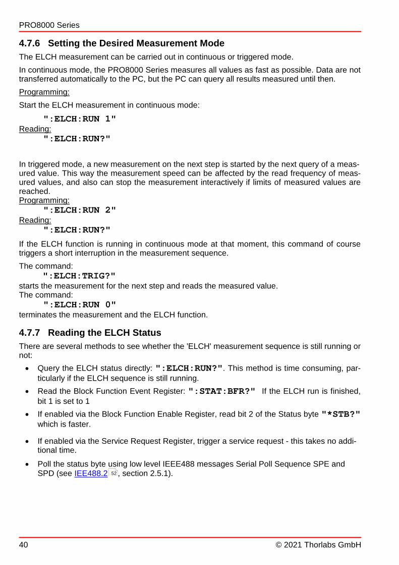
4.7.6 Setting the Desired Measurement Mode
The ELCH measurement can be carried out in continuous or triggered mode.
In continuous mode, the PRO8000 Series measures all values as fast as possible. Data are nottransferred automatically to the PC, but the PC can query all results measured until then.
Programming:
Start the ELCH measurement in continuous mode:
":ELCH:RUN 1"Reading:
":ELCH:RUN?"
In triggered mode, a new measurement on the next step is started by the next query of a meas-ured value. This way the measurement speed can be affected by the read frequency of meas-ured values, and also can stop the measurement interactively if limits of measured values arereached.Programming:
":ELCH:RUN 2"Reading:
":ELCH:RUN?"
If the ELCH function is running in continuous mode at that moment, this command of coursetriggers a short interruption in the measurement sequence.
The command:":ELCH:TRIG?"
starts the measurement for the next step and reads the measured value.The command:
":ELCH:RUN 0"terminates the measurement and the ELCH function.
4.7.7 Reading the ELCH Status
There are several methods to see whether the 'ELCH' measurement sequence is still running ornot:
· Query the ELCH status directly: ":ELCH:RUN?". This method is time consuming, par-ticularly if the ELCH sequence is still running.
· Read the Block Function Event Register: ":STAT:BFR?" If the ELCH run is finished,bit 1 is set to 1
· If enabled via the Block Function Enable Register, read bit 2 of the Status byte "*STB?"which is faster.
· If enabled via the Service Request Register, trigger a service request - this takes no addi-tional time.
· Poll the status byte using low level IEEE488 messages Serial Poll Sequence SPE andSPD (see IEE488.2 , section 2.5.1).52

© 2021 Thorlabs GmbH
4 Communication With a PC
41
4.7.8 Reading the Measured Values
The command
":ELCH:TRIG?"
allows to step through the list of measured values.
If using this command more often than measurement steps were defined, the last answer stringwill be repeatedly read out.
Example of an answer string:
7.12345678E-003,6.94673825E-002,1.00453298E+000<LF>
The command:
":ELCH:GETALL?"
retrieves all measured data of the ELCH run at once. Depending on the number of measure-ment values, this can take a considerable time.
Example:
1001 measurement values with 8 readout values results in 1001 * (1 set + 8 read) * 17 Byte / value + 2 ...3 Byte string terminator = max. 153156 Byte!
For this reason, make sure that the input buffer is of a sufficient size and that the IEEE timeoutis set in order to avoid a timeout error. So if refer to above example, the read-out of 1001 mea-surements with 9 values takes around 40 seconds.
Example of answer string (measured values separated by comma, measurement points - bysemicolon):
1.00000005E-003,9.79492208E-004;3.25000030E-003,3.23242205E-003;5.50000044E-003,5.47656277E-003;7.75000080E-003,7.73339858E-003;1.00000007E-002,9.98535194E-003;
Note
Please keep in mind, that the IEEE488 bus traffic of all connected hosts is suspended as longas the data transfer from the PRO8000 Series to the control PC running. In order to allowIEEE488 traffic in between, your program needs to interrupt the data transfer. Make sure, that the size of the input buffer is sufficient.
If using the ":ELCH:GETALL?" command while the ELCH routine is still running, only
measured data up to this point are transmitted. The ":ELCH:GETALL?" command can be
used then again to retrieve the rested data, or proceed with the ":ELCH:TRIG?" command.
The command:
":ELCH:RESET?"
returns the remaining number of measurement values.
The command
":ELCH:RESET 0"
resets the internal ELCH counters to zero. Recorded but not read-out yet prior to that data arebeing overwritten by the next ELCH run.

© 2021 Thorlabs GmbH42
PRO8000 Series
4.7.9 Example of an ELCH Measurement Procedure
The following example of an ELCH sequence measures the photo current of the monitor diodeof a laser and the current of an external photo diode, dependent on the laser current.
The Laser Diode Current controller (LDC8xxx) is in slot 2, the external photodiode is connectedto input 1 of the PDA8000-2 Photodiode Amplifier in slot 3.
Command Explanation
":SLOT 2" Select the LDC8xxx module in slot 2
":ILD:START 10e-3" Start value for ILD = 10 mA
":ILD:STOP 100e-3" Stop value for ILD = 100 mA
":ELCH:STEPS 101" The LD current range is divided in 101 steps
":ELCH:MEAS 3" 3 measurements for every step
":VLD:MEAS 1" Select VLD (measured) to be on position 1 in the outputstring
":IMD:MEAS 2" Select IMD to be on position 2
":SLOT 3" Select module in slot 3
":PORT 1" Select input port 1 of the photo-amplifier module
":IPD:MEAS 3" Select measured photocurrent of module 3 on position 3
":SLOT 2" Return to slot 2 to the module that generates the independ-ent parameter, i.e., the value that is stepped through. Man-datory when starting ELCH.
":LASER ON" Switch on the laser
Remark: As Thorlabs laser diode controllers use a soft start function in order to protect the laser diode,a wait time of 1 to 2 seconds needs to be inserted in order to settle the laser current.
":ELCH:RESET 0" Resets the ELCH data pointers
":ELCH:RUN 1" Starts ELCH measurement in continuous mode
":ELCH:TRIG?" Requests the first measurement string:
ILD (set) VLD (read) IMD (read) IPD (read)
Position 0 1 2 3
7.12500000E-003, 7.12345678E-001, 3.34673825E-004, 1.00453298E-003<LF>
":ELCH:TRIG?" Request the next measurement string
":ELCH:RESET?" Shows the number of remaining values
Repeat until all values are read or use the single command:
":ELCH:GETALL?"
to retrieve all data measured in a single step.
Attention
If using this command make sure, that the input buffer is of a sufficient size (up to160kB) and that the IEEE488 timeout is set to an appropriate value (up to 50 sec.).

© 2021 Thorlabs GmbH
4 Communication With a PC
43
If using the ":ELCH:GETALL?" command during the running measurement, only the datathat were acquired up to then are retrieved. Use this command again to retrieve the remainingdata.
":ELCH:RUN 0" Stops the ELCH function.
4.7.10 Possible ELCH Error Sources
Ø “310, ELCH set value initialization not complete”
· The value that was selected as the independent variable is not allowed for this purpose,e.g. values which are calculated from others. Please refer to the operation manual of theindividual module. Any command that offers the compound ":MEAS n" can be used.
· The given START and STOP values either belong to different commands or / and to dif-ferent modules.
· The selected modules initialization is not completed yet.
· The selected module is not switched on.
· The module that provides the independent variable was not selected when starting ELCH(Missing command ":SLOT n")
Ø “311, ELCH read value(s) initialization not complete”
· A value that is not a measurement value (e.g. P share) was assigned as a read value.Any command that offers the compound ":ACT?" can be used.
· The selected module was not correctly initialized. For example from a TED8xxx modulethe resistance of a thermistor temperature sensor was attempted to read while the TEDmodule was set to an AD590 temperature sensor.
· Wrong number of dependent values. For example, 3 dependent values were specified by":ELCH:MEAS 3" but only 2 dependent values are set by
":ILD:MEAS 1; :TEMP:MEAS 2"
Ø “312, ELCH was stopped”
· ELCH was stopped by use
· An error has occurred in a module (e.g. interlock open)
Ø Errors while using the data read-out commands :"ELCH:GETALL?" or
":ELCH:TRIG?"
e.g. "Timeout expired before operation completed"or "The number of bytes transferred is equal to the inputcount"· Insufficient timeout
· Insufficient input buffer size
· Not all measured data could be retrieved: Perhaps, the measurement is still in progress.Either check the ELCH status or use the ":ELCH:GETALL?" command again toretrieve the rest of the data.
· The retrieved data do not start with the expected first set value: Possibly, the data of aprevious ELCH run were not read out. To avoid this, start the ELCH run using the":ELCH:RESET 0" command in order to discard previously measured values.
40

© 2021 Thorlabs GmbH44
PRO8000 Series
5 Maintenance and ServiceProtect the PRO8000 Series from adverse weather conditions. The PRO8000 Series is not wa-ter resistant.
Attention
To avoid damage to the instrument, do not expose it to spray, liquids or solvents!
The unit does not need a regular maintenance by the user. It does not contain any modulesand/or components that could be repaired by the user himself. If a malfunction occurs, pleasecontact Thorlabs for return instructions.
Do not remove covers!
General care
Protect the PRO8 from adverse weather conditions. The PRO8 is not water resistant.
Attention
To avoid damage to the PRO8, do not expose it to spray, liquids or solvents!
Cleaning
The unit and the display window can be cleaned with a cloth dampened with water. You canuse a mild 75% Isopropyl Alcohol solution for more efficient cleaning.
Line voltage
The PRO8000 Series mainframes operate at fixed line voltages of 90 to 110 V, 104 to 127 Vand 207 to 253 V. Prior to starting the operation, check that the line voltage as specified on theletter plate matches your local supply voltage. A qualified service person is required to changethe operating line voltage. See section Changing Line Voltage Setting for instructions.
5.1 Installing and Uninstalling Modules
Attention
PRO8000 Series module(s) must not be installed or uninstalled when the mainframe isswitched on. Otherwise, severe damages may occur to the module(s) and/or the mainframe!
The PRO8000 Series has a modular design and can be operated with a variety of differentmodules. The change of modules or retro-fitting of modules can be done by the user himself.
It is not necessary to re-adjust the modules after installation.
The number of modules that can be used simultaneously is limited by the number of slots.Modules can be installed to any of the slots.
After switching on the PRO8000 Series will recognize each new configuration automatically.
Uninstalling a module
· Switch off the mainframe and remove the mains cable from the mains jack. The modules areuninstalled from the front of the unit.
· Modules of standard width are fixed with two screws, modules with double width - with fourscrews.
· Pull out the modules using the handle.
· Unused slots must be covered using a blind plate.
58
46

© 2021 Thorlabs GmbH
5 Maintenance and Service
45
Installing a module
· Depending on the required width of the module a sufficient number of slots must be free; un-install modules (see above) or remove blind plates.
· Insert the module into the guide rail of the slot and push until it locks in.
· Fix the modules with the appropriate number of screws.
· Check the function of the modules by switching on the mainframe. All installed modules mustbe recognized correctly in the setup menu.
Note
In case a new module has been installed, it will be initialized using it’s default settings. When switching off the PRO8 mainframe, any settings that were made to the module(s) aresaved and are restored after power-on, as long as the module was not moved to another slot. If relocating a module, it will be recognized after power-on with its default settings; any settingsthat were made previously, are lost.
5.2 Exchanging the Mains Fuse
The line fuse is located on the rear panel, in a small compartment of the mains connector. Itcan be exchanged easily without opening the cabinet.
Attention
Use only the fuse value corresponding to the line voltage!
· Switch off the mainframe and remove the mains cable from the mains jack.
· Use a screwdriver to remove the lid of the fuse holder. A small drawer opens. The replace-ment fuse becomes visible, if provided. The active fuse is in the back of the drawer.
· Remove the fuse holder completely and exchange the blown fuse. Use an IEC 60127-2/V, 5 x20 mm, 250 V fuse with slow response and high breaking capacity according to the table be-low:
Line Voltage PRO8000 PRO8000-4 PRO800
100 V ±10% T5H250V T8H250V T2.5H250V
115 V ±10% T5H250V T8H250V T2.5H250V
230 V ±10% T2.5H250V T4H250V T1.25H250V
· Place back the fuse holder.
· Switch on the mainframe. If the unit cannot be switched on even with the correct fuse inser-ted, please contact Thorlabs .58

© 2021 Thorlabs GmbH46
PRO8000 Series
5.3 Changing the Line Voltage Setting
Warning
Dangerous or even lethal voltages inside the unit! Any service procedure, e.g. changing of the line voltage setting or replacement of the in-ternal fuses, must be done only by qualified service personnel!
Attention
Remove the power cord prior to opening the mainframe housing!Even after disconnecting the mains cable, dangerous voltages may be present inside theunit!
The PRO8000 Series operates with line voltages of 100 V ±10%, 115 V ±10% or 230 V ±10%.
Prior to switching on the unit make sure that the voltage stated on the letter plate is in accor-dance with the locally supplied line voltage.
The setting of the line voltage is determined by the wiring of the transformer connector terminalat the left side panel inside the unit.
After changing the line voltage, make sure to change also the appropriate line fuse (see sectionExchanging the Mains Fuse ).
Procedure
· Switch off the mainframe and disconnect the power cord.· Remove the upper two plastic feet by unscrewing the hex screws on the rear panel and re-
move the upper housing cover.· Install the gray cable to the corresponding clamp, as marked on the terminal. The cable is re-
leased from the clamp by pressing and holding down the clamp spring with a screwdriver. · Place back the upper housing cover and screw on the plastic feet.· Check the mains fuse and its replacement for corresponding to the set line voltage; ex-
change them if necessary.
· Finally, place the marker screw on the rear panel to the right position, according to the setline voltage.
45

© 2021 Thorlabs GmbH
5 Maintenance and Service
47
PRO8000 - Marker Screw for 230 V
5.4 Replacement of Internal Fuses
Warning
Dangerous or even lethal voltages inside the unit! Any service procedure, e.g. changing of the line voltage setting or replacement of the in-ternal fuses, must be done only by qualified service personnel!
Attention
Remove the power cord prior to opening the mainframe housing!Even after disconnecting the mains cable, dangerous voltages may be present inside theunit!
Procedure
· Switch off the mainframe and disconnect the power cord.· Remove the upper two plastic feet by unscrewing the hex screws on the rear panel and re-
move the upper housing cover.
· Name, type and location of the internal fuses are given on the adhesive labels.
· Replace the defective fuse.
· Place back the upper housing cover and screw on the plastic feet.
© 2021 Thorlabs GmbH48
PRO8000 Series
5.5 Troubleshooting
In case that your PRO8000 Series system shows malfunction please check the following items:
u The mainframe does not work at all (no display on the mainframe):
Ø Is the mainframe connected properly to the mains power supply?· Connect the mainframe to the power line, take care of the correct voltage setting and
grounding of the mainframe.
Ø Is the mainframe turned on?
· Turn on the power key switch.
Ø Check the fuse at the rear panel of the mainframe.
· If blown, replace the fuse with the correct type (one spare fuse is inserted in the fuseholder). Please refer to section Exchanging the Mains Fuse .
u The display works, but not the module:
Ø Is the module inserted correctly and are all mounting screws tightened?
· Insert the module in the desired slot and tighten all mounting screws properly.· See the individual manual of the module for further troubleshooting.
u The installed IEEE488 interface does not respond to the connected computer
Ø Is the option “Interface: IEEE488” selected in the setup menu?
· Press “ESC” until entering the setup menu. Use the arrow soft keys to select the in-terface line, press the change button and select IEEE488 interface. See SetupMenu .
Ø Is the correct type of IEEE488 connecting cable used?
· Install the appropriate cable.
Ø Was the cable installed after turning on the mainframe or the PC?
· Turn off both units and turn them on again.
Ø Does the mainframe's device address match with the address in the control software?
· Refer to section Setup Menu to see the present IEEE488 bus address of the main-frame and make sure that it matches with the control software (default address is 10).Alternatively, you may change the actual IEEE address of the mainframe corre-sponding to the software.
Ø Is there an address conflict on the IEEE488 bus interface? Check if there is anotherdevice using the same address.
· Make sure that each of the present devices has its individual address.
u The installed RS232 interface does not respond to the connected computer
Ø Is the option “Interface: RS232” selected in the setup menu?
· Press “ESC” until entering the setup menu. Use the arrow soft keys to select the in-terface line, press the change button and select RS232 interface. See Setup Menu.
Ø Is the correct type of serial cable used?
45
13
13
13

© 2021 Thorlabs GmbH
5 Maintenance and Service
49
· Install the appropriate cable, see Hardware Standard RS232C .
u With the first RS232 command, the mainframe enters the remote mode, but does notrespond further
Ø Check the selected baud rate.
· The baud rates in the PRO8000 Series setup menu and in the control software mustmatch.
u The LOCAL key of the mainframe is not responding
Ø The "LLO" (Local Lockout) command might have been sent to mainframe, this way dis-
abling the LOCAL key.
· In order to return to local mode, from the PC the command "GTL" (Go To Local)must be sent.
· The LOCAL key is enabled when turning off and on again the mainframe.
u Displayed measured values seem to react only very slowly
Ø Adjust the over sampling rate (OSR) in the setup menu to a lower value.
If above hints could not resolve the malfunction, please contact Thorlabs for technical sup-port and/or return instructions.
14
13
58

© 2021 Thorlabs GmbH50
PRO8000 Series
6 Appendix
6.1 Technical Data
Common PRO800 PRO8000 PRO8000-4
Number of Slots 2 8 8
Mains Switch Key Operated
Remote Control Via IEEE488 and RS232C
Power Supply
Mains Voltage 100 V, 115 V, 230 V ±10%, Fixed
Mains Frequency 50 to 60 Hz
Maximum Power Consumption 220 VA 500 VA 800 VA
Supply Mains Overvoltage Category II (Cat II)
Maximum Output Current per Slot 4 A 4 A 4 A
Maximum Output Current, all Slots 8 A 16 A 32 A
Display and Operating Elements
Display 4 x 20 characters alphanumeric vacuum-fluorescence-display
User Interface Interactive Menus
Keypad 7 Micro-Switch Keys
Main Tuning Knob Rotation Encoder
Acoustic MessagesInternal Beeper:
Short Tone As Confirmation, Long Tone As Warning
Connectors On Rear Panel
Ground 4 mm Banana Jack
Power Line Line 3 pin IEC 320 with fuse
Remote ControlIEEE488 (24 pin.)
RS232C (9 pin) D-SUB
Auxiliary Jack 9-pin D-Sub. For extensions
TRIG IN (max. 5V, TTL) BNC
TRIG OUT (max. 5V, TTL) BNC
Protections
· Key Operated Power Control Switch (ON / STANDBY)· Interlock Connector· Over Temperature Protection of the Mainframe· Over Temperature Protection of the PRO8000 Series Modules· Protection Against Transients· Protection Against Interrupted Wiring (OPEN)· Protection Against Too High Laser or TEC Current (Hardware and Software Limit)· Protection Against Too High Optical Power (Current Limit of the Monitor Diode)
General
Warm-Up Time for Rated Accuracy 10 min
Operating Temperature Range 1) 0 to +40 °C
Storage Temperature Range -40 to 70 °C
Relative Humidity Max. 80% up to 31° C, decreasing to 50% at 40° C
Pollution Degree (Indoor Use Only) 2
Operation Altitude < 2000 m
Dimensions (W x H x D) 232 x 147 x 396 mm 449 x 147 x 396 mm 449 x 177 x 456 mm
Weight < 9 kg < 17 kg < 21 kg
1) non-condensing
All technical data are valid at 23 ± 5°C and 45 ± 15% rel. humidity (non condensing)

© 2021 Thorlabs GmbH
6 Appendix
51
6.2 Certifications and Compliances

© 2021 Thorlabs GmbH52
PRO8000 Series
6.3 Letter of Volatility
Model Memory Size Memory Type,
Purpose
Volatility User Data Method of Clearing
PRO800,
PRO8000,
PRO8000-4
up to1MB RAM, runtime data no, battery
buffered
no* Cannot be cleared by user
PRO800,
PRO8000,
PRO8000-4
up to 4MB Flash, firmware no no Cannot be cleared by user
LDC8000 series 256 B EEPROM, calibra-
tion data
no no Cannot be cleared by user
TED8000 series 256 B EEPROM, calibra-
tion data
no no Cannot be cleared by user
ITC8000 series 256 B EEPROM, calibra-
tion data
no no Cannot be cleared by user
PDA8000 series 256 B EEPROM, calibra-
tion data
no no Cannot be cleared by user
MLC8000 series 256 B EEPROM, calibra-
tion data
no no Cannot be cleared by user
OSW8000 series 256 B EEPROM, calibra-
tion data
no no Cannot be cleared by user
WDM8000 series 2KB EEPROM, calibra-
tion data
no no Cannot be cleared by user
(*) device settings like ‘selected channel’ or ‘set current’ are stored here, user cannot enter arbitrary data
6.4 Literature
[1] IEEE488.2-1992 - IEEE Standard Codes, Formats, Protocols, and Common Commandsfor Use With IEEE Std 488.1-1987, IEEE Standard Digital Interface for Programmable In-strumentation
Available at http://www.ieee.org/publications_standards/index.html .

© 2021 Thorlabs GmbH
6 Appendix
53
6.5 Warranty
Thorlabs GmbH warrants material and production of the PRO8000 Series for a period of 24months starting with the date of shipment. During this warranty period Thorlabs GmbH will seeto defaults by repair or by exchange if these are entitled to warranty.
For warranty repairs or service the unit must be sent back to Thorlabs GmbH. The customer willcarry the shipping costs to Thorlabs GmbH, in case of warranty repairs Thorlabs GmbH willcarry the shipping costs back to the customer.
If no warranty repair is applicable the customer also has to carry the costs for back shipment.
In case of shipment from outside EU duties, taxes etc. which should arise have to be carried bythe customer.
Thorlabs GmbH warrants the hard- and/or software determined by Thorlabs GmbH for this unitto operate fault-free provided that they are handled according to our requirements. However,Thorlabs GmbH does not warrant a fault free and uninterrupted operation of the unit, of thesoftware or firmware for special applications nor this instruction manual to be error free.Thorlabs GmbH is not liable for consequential damages.
Restriction of Warranty
The warranty mentioned before does not cover errors and defects being the result of impropertreatment, software or interface not supplied by us, modification, misuse or operation outsidethe defined ambient stated by us or unauthorized maintenance.
Further claims will not be consented to and will not be acknowledged. Thorlabs GmbH does ex-plicitly not warrant the usability or the economical use for certain cases of application.
Thorlabs GmbH reserves the right to change this instruction manual or the technical data of thedescribed unit at any time.

© 2021 Thorlabs GmbH54
PRO8000 Series
6.6 Copyright and Exclusion of Liability
Thorlabs GmbH has taken every possible care in preparing this document. We however as-sume no liability for the content, completeness or quality of the information contained therein.The content of this document is regularly updated and adapted to reflect the current status ofthe hardware and/or software. We furthermore do not guarantee that this product will functionwithout errors, even if the stated specifications are adhered to.
Under no circumstances can we guarantee that a particular objective can be achieved with thepurchase of this product.
Insofar as permitted under statutory regulations, we assume no liability for direct damage, indir-ect damage or damages suffered by third parties resulting from the purchase of this product. Inno event shall any liability exceed the purchase price of the product.
Please note that the content of this document is neither part of any previous or existing agree-ment, promise, representation or legal relationship, nor an alteration or amendment thereof. Allobligations of Thorlabs GmbH result from the respective contract of sale, which also includesthe complete and exclusively applicable warranty regulations. These contractual warranty regu-lations are neither extended nor limited by the information contained in this document. Shouldyou require further information on this product, or encounter specific problems that are not dis-cussed in sufficient detail in the document, please contact your local Thorlabs GmbH dealer orsystem installer.
All rights reserved. This document may not be reproduced, transmitted or translated to anotherlanguage, either as a whole or in parts, without the prior written permission of Thorlabs GmbH.
Copyright © Thorlabs GmbH 2021. All rights reserved.

© 2021 Thorlabs GmbH
6 Appendix
55
6.7 Thorlabs 'End of Life' Policy
As required by the WEEE (Waste Electrical and Electronic Equipment Directive) of theEuropean Community and the corresponding national laws, Thorlabs GmbH offers all endusers in the EC the possibility to return “end of life” units without incurring disposal charges.
This offer is valid for Thorlabs GmbH electrical and electronic equipment
· sold after August 13th 2005 · marked correspondingly with the crossed out “wheelie bin” logo (see figure below)· sold to a company or institute within the EC · currently owned by a company or institute within the EC · still complete, not disassembled and not contaminated
As the WEEE directive applies to self contained operational electrical and electronic products,this “end of life” take back service does not refer to other Thorlabs GmbH products, such as
· pure OEM products, that means assemblies to be built into a unit by the user (e. g. OEMlaser driver cards)
· components · mechanics and optics · left over parts of units disassembled by the user (PCB’s, housings etc.).
Waste treatment on your own responsibility
If you do not return an “end of life” unit to Thorlabs GmbH, you must hand it to a company spe-cialized in waste recovery. Do not dispose of the unit in a litter bin or at a public waste disposalsite.
WEEE Number (Germany) : DE97581288
Ecological background
It is well known that waste treatment pollutes the environment by releasing toxic products dur-ing decomposition. The aim of the European RoHS Directive is to reduce the content of toxicsubstances in electronic products in the future.
The intent of the WEEE Directive is to enforce the recycling of WEEE. A controlled recycling ofend-of-life products will thereby avoid negative impacts on the environment.
Crossed out "Wheelie Bin" symbol

© 2021 Thorlabs GmbH56
PRO8000 Series
6.8 List of Acronyms
AG Anode Ground
BFC Block Function Condition Register
BFE Block Function Enable Register
BFR Event Register
CG Cathode Ground
CRD Character Response Data
DBR Distributed Bragg Reflector
DCL Device Clear
DEC Device Error Condition Register
DEE Device Error Event Register
DES Device Error Status
DESE Device Error Summary Enable Register
DESR Device Error Summary Register
EAV Error AVailable
EDE Enable Device Error Event Register
ELCH ELectrical Characterization
EOI End Of Information
ESB Error Status Byte
ESE Standard Event Status Enable register
ESR Event Status Register
FIN Command FINished
GET Group Execute Trigger
GTL Go To Local
GPIB General Purpose Interface Bus
IEEE Institute for Electrical and Electronic Engineering
ITU International Telephone and Telegraph Union
LF Line Feed
LLO Local Lockout
LS Laser Source Module
NR1 Numeric Response data of type 1
NR2 Numeric Response data of type 2
NR3 Numeric Response data of type 3
MAV Message AVailable)
MSS Master Summary Status
PC Personal Computer
PD Photo Diode
RQS ReQuest Service Message
SDC Selected Device Clear
SEL SELect

© 2021 Thorlabs GmbH
6 Appendix
57
SRE Service Request Enable Register
SRQ Service ReQuest
STB STatus Byte Register
SW Soft Ware
TEC ThermoElectric Cooler (Peltier Element)
TRG TRiGger
TTL Transistor-Transistor Logic
WDM Wavelength Division Multiplex

© 2021 Thorlabs GmbH58
PRO8000 Series
6.9 Thorlabs Worldwide Contacts
For technical support or sales inquiries, please visit us at www.thorlabs.com/contact for ourmost up-to-date contact information.
USA, Canada, and South America Thorlabs, Inc. [email protected] [email protected]
UK and Ireland Thorlabs Ltd. [email protected] [email protected]
Europe Thorlabs [email protected]
Scandinavia Thorlabs Sweden AB [email protected]
France Thorlabs SAS [email protected]
Brazil Thorlabs Vendas de Fotônicos Ltda. [email protected]
Japan Thorlabs Japan, Inc. [email protected]
China Thorlabs China [email protected]

www.thorlabs.com


![Mainframes Refresher[2]](https://static.fdocuments.in/doc/165x107/577d20a81a28ab4e1e936e78/mainframes-refresher2.jpg)