PRO SERIES - MTC Optics
12
PRO SERIES edition 3 VIPER PRO • VIPER PRO TACTICAL • MAMBA PRO 2 • MAMBALITE USERS MANUAL
Transcript of PRO SERIES - MTC Optics

PRO SERIESedition 3
VIPER PRO • VIPER PRO TACTICAL • MAMBA PRO 2 • MAMBALITE
USERS MANUAL
FORWARD
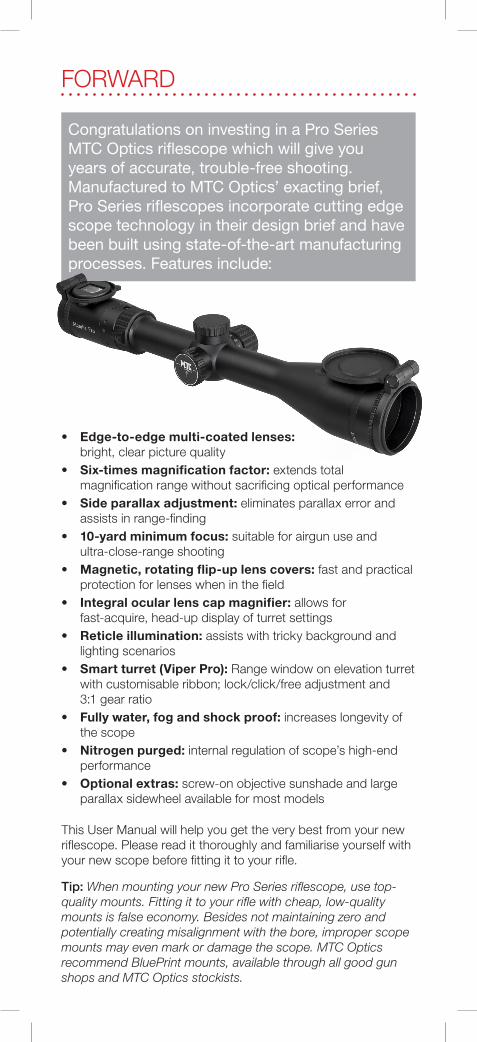
Congratulations on investing in a Pro Series MTC Optics riflescope which will give you years of accurate, trouble-free shooting. Manufactured to MTC Optics’ exacting brief, Pro Series riflescopes incorporate cutting edge scope technology in their design brief and have been built using state-of-the-art manufacturing processes. Features include:
• Edge-to-edge multi-coated lenses: bright, clear picture quality• Six-times magnification factor: extends total magnification range without sacrificing optical performance • Side parallax adjustment: eliminates parallax error and assists in range-finding• 10-yard minimum focus: suitable for airgun use and ultra-close-range shooting• Magnetic, rotating flip-up lens covers: fast and practical protection for lenses when in the field• Integral ocular lens cap magnifier: allows for fast-acquire, head-up display of turret settings• Reticle illumination: assists with tricky background and lighting scenarios• Smart turret (Viper Pro): Range window on elevation turret with customisable ribbon; lock/click/free adjustment and 3:1 gear ratio• Fully water, fog and shock proof: increases longevity of the scope• Nitrogen purged: internal regulation of scope’s high-end performance• Optional extras: screw-on objective sunshade and large parallax sidewheel available for most models
This User Manual will help you get the very best from your new riflescope. Please read it thoroughly and familiarise yourself with your new scope before fitting it to your rifle.
Tip: When mounting your new Pro Series riflescope, use top-quality mounts. Fitting it to your rifle with cheap, low-quality mounts is false economy. Besides not maintaining zero and potentially creating misalignment with the bore, improper scope mounts may even mark or damage the scope. MTC Optics recommend BluePrint mounts, available through all good gun shops and MTC Optics stockists.

CARE AND MAINTENANCEMTC’s Pro Series riflescopes are precision optical instruments, so they need to be treated with care. When cleaning the exterior, use a soft, damp cloth and dry off the surface afterwards. Keep the scope’s lens covers closed whenever your scope is not in use to protect the font (objective) and rear (ocular) lenses.
Important: Should you need to clean the lenses, do so with extreme care to avoid scratching or damaging their expensive coatings. Use a camera-quality ‘puffer brush’ to blow off excess dirt, which should then be gently brushed away. Should any dirt remain, put a drop of alcohol-based cleaning fluid on a lint-free cloth and lightly rub the area in a circular motion. Do not apply excessive pressure as this could damage the lens surface and invalidate the warranty.
Should you have any questions, please contact your local MTC Optics supplier, or MTC directly via e-mail: [email protected].
BEFORE STARTINGPlease familiarise yourself with the layout of your new MTC Optics Pro Series scope, and the terminology used in this manual (see figure1).
1. Objective 2. Lens cap (flip-up style) 3. Body tube 4. Elevation turret 5. Windage turret 6. Side turret (parallax/illumination) 7. Magnification ring (zoom) 8. Fast-focus ring 9. Ocular (eye-bell)
WARNING NEVER LOOK DIRECTLY AT THE SUN OR ANY BRIGHT
LIGHT THROUGH YOUR SCOPE - PERMANENT EYE INJURY OR EVEN BLINDNESS CAN RESULT
Figure 1: Scope Anatomy
12
23
4
5
6
7
8
9

USING THE SCOPEMounting to the rifle
Use mounts with appropriate diameter rings – 30mm (Viper Pro/Tactical; Mamba Pro 2) or 25mm (MambaLite Pro). They should be high enough to allow the scope’s objective (front) bell to clear the rifle, but still allow a comfortable head position on the rifle’s comb when sighting through the eyepiece. Set the eye relief so that you see a sharply-defined sight picture – your eye should not be pressed against the eye-bell. Ensure that the vertical crosshair is perpendicular to the ground by aligning it with a vertical edge – use a plumb line if necessary. Avoid canting the rifle during this process – aligning the action with a spirit level will help in this respect. (See also section: Shimming.)
Eye-bell controls (Figure 2)
Set the scope’s primary focus by turning the serrated fast-focus ring to suit your aiming eye. Turn it toward either the + or – sign printed on the eye-bell while looking at a neutral background until the crosshair looks sharpest. (Tip: do not look through the scope for more than a few seconds at a time when setting up the focus, and never look at the sun.) You can undertake this operation on any magnification setting.
Parallax focusing (Figure 3)
Look at a target with the scope on full magnification and, using the side parallax adjusting ring, focus the sight picture until it is sharpest. Always shoot with a sharp sight picture to ensure parallax error has been eliminated. The distance vernier on the side parallax ring can also serve as a range-finding guide. (Tip: this works best on the highest magnification.)
Figure 2: Eye-bell controls
Figure 3: Turret controls
(viewed from eye-bell)
Fast-focus adjustment ring
Numbered verniers
Parallax distance vernier
Parallax control ring
Reticle illumination
button
Rheostat battery cover
Magnification (zoom) ring
ELEVATION TURRET
WINDAGE TURRET
SIDE TURRET

1/2 MIL1 MIL
1/2 MIL
5 MIL
CENTRE CROSS +/- 1/2 MIL1 MIL TOTAL
MIL SPACINGS TRUE ON X 10
Figures 4/4a: Optional large parallax adjustment sidewheel
A 75mm diameter sidewheel is also available as an optional extra (figure 4). To fit this, slacken the three 2mm locking screws on the inner ring of the big sidewheel and slide onto the scope’s side turret (figure 4a), ensuring alignment of the range-markings on both. Tighten the screws to secure the wheel in place. Note that the ranges are a guide only and may need modification to suit user-specific eyesight.
SCB2 Crosshair
The second-generation Small Calibre Ballistic (SCB2) reticle is suitable for all airguns and firearms as its multi-stadia design provides a multitude of aiming reference marks for holdover, holdunder and wind allowance (figure 5). Its design is based around milliradian spacings (‘true’ at 10x power). A milliradian is known as a ‘MIL’ and 1 MIL = 3.6” at 100 yards (7.2” @ 200yds; 1.8” @ 50yds etc). This means it can also be used for range-finding provided the scope’s magnification ring is set to 10x. Detailed information on mil-based range-finding can be found at mtcoptics.com
Figure 5: MIL markings of SCB2 crosshair

Illumination control
For tricky lighting conditions, the central area of the scope’s crosshair can be illuminated. To turn it on, long-press the centre button located in the middle of the parallax side turret (see figure 3). The intensity of the crosshair’s illumination can be changed to one of six levels by short-pressing the button. A long-press will switch off the illumination. The last brightness setting will be restored when next switching on the crosshair illumination. The rheostat is powered by a CR2032 battery, accessed by unscrewing the rheostat cover on the side turret.
Turret operation
All Pro Series offer 1/4MOA elevation and windage turrets with clock-stop adjustment (1 click = ¼” @ 100yds) for precise zeroing, and their verniers can be re-set to ‘0’ for at-a-glance reference. The method by which this is done, and any additional features that may be model specific, are explained in detail elsewhere. Refer to the instructions relevant to your model in the section: Setting the adjustment turrets and figures 8-10.
Zeroing-in
Initially, set a target at 15 yards (or bore site the scope) and, aiming at a mark, shoot three shots to observe the point of impact (POI). Adjust the elevation and windage adjusters in the direction the POI needs to shift to strike where the central crosshair is. For example, if the group strikes the target low and right of your aiming point, adjust the elevation turret in the direction marked ‘UP’ (U) and the windage turret in the direction marked ‘Left’ (L). When the group is roughly centre, move the target to your usual shooting distance (known as zero) and repeat the process to fine-tune the POI. (Tip: carry out zeroing in windless conditions.) When you are happy your rifle is zeroed, set the turret vernier rings to ‘0’.
Note: On the Viper Pro model, turn the elevation turret clockwise to raise the POI; turning its windage turret clockwise moves the POI to the left. See section: Setting the adjustment turrets.
Shimming
Ideally, your scope should be zeroed to your rifle as near to the middle of its adjustment range as possible. On some rifles, to achieve this it is necessary to ‘shim’ the lower cradle of the rear mount using a thin sliver of silver foil. This can be folded for extra adjustment, but it should not exceed 0.3mm thickness to avoid damaging the scope.
Figure 6: Shimming the rear mount

MTC ships scopes from the factory with the adjusters in the mid-point position, but you should always check that they are set in the middle before zeroing your scope on a rifle for the first time. If, with the scope’s elevation adjustment turret set to its mid-point, the initial POI is a long way below the central crosshair, you will need to shim the cradle of the rear mount (figure 6).
Note: Shimming is more likely to be required on a high-magnification scope (such as the Viper Pro 5-30x50).
Flip-up covers
Besides offering protection of the lenses, the flip-up lens covers supplied with MTC’s Pro Series scopes can be rotated so that they open to suit the user’s preference/equipment. Loosen the knurled locking ring to reposition the hinge as required and re-tighten the cover in place (figure 7). Ensure the eye-bell cover is not positioned to cause injury to your brow during the rifle’s recoil. Additionally, the eye-bell cover features a small magnifier to assist with head-up viewing of turret markings (figure 7a).
Figures 7/7a: Flip-up lens covers, showing eye-bell cover’s magnifier

SETTING THE ADJUSTMENT TURRETSThe elevation and windage turrets on all Pro Series scopes allow the user to precisely zero the rifle (refer section: Zeroing-in). While all models offer 1/4MOA click adjustment (1 click = ¼” @ 100yds), their operation differs between models.
Mamba Pro 2 / MambaLite Pro (Figure 8)
• Unscrew the protective dust caps to expose the finger- adjustable turrets • To alter the point of impact (POI) of the shot up or down, turn the elevation (top) turret in either the ‘U’ or ‘D’ direction • To alter the POI of the shot left or right, turn the windage (right) turret in either the ‘L’ or ‘R’ direction • To reset the vernier to ‘0’ (t), slacken the hex-headed grubscrew in the knurled section until the vernier spins freely. Turn the vernier so that the t corresponds to the guideline on the drum, then re-tighten the grubscrew
Viper Pro Tactical (Figure 9)
• The external ‘tactical’ turrets feature a locking system to stop them inadvertently turning. Tighten or slacken the scalloped ring at the base of the elevation (top) and windage (right) turrets to lock or unlock respectively
• To alter the point of impact (POI) of the shot up or down, turn the elevation (top) turret in either the ‘U’ or ‘D’ direction
• To alter the POI of the shot left, turn the windage turret clockwise. To alter the POI of the shot right, turn the windage turret anti-clockwise
• To reset the vernier to ‘0’ (t), slacken the hex-headed grubscrews in the knurled section until the vernier spins freely. Turn the vernier so that the t corresponds to the s guideline on the drum, then re-tighten the grubscrews
ELEVATION TURRET
Grubscrew
WINDAGE TURRETGrubscrew
Vernier
Drum
Reference Guideline
Figure 8

Viper Pro (Figures 10 and 10a)
This model features Smart turrets with a 3:1 gearing system for super-precise control, along with a host of other useful features. Both the elevation and windage turret incorporate a locking system to stop them turning inadvertently. The user can choose elevation POI adjustment by way of click or click-free turns. Besides an external vernier ring, a small window in the elevation turret allows the user to view alternative graduations by way of a vernier range-tape. A blank tape (90x7mm) may even be customised to suit the specific trajectory of the user’s own rifle/ammo combo (refer to MTC Optics’ website at: www.mtcoptics.com/range-tape-calculator).
• To lock the elevation (top) turret, move the switch at its base so the arrow points to the ‘Lock’ position
• To lock the windage (right) turret, move its base switch so the arrow points to the uppermost mark
• To alter the point of impact (POI) of the shot up or down, move the switch from ‘Lock’ and choose either ‘Click’ adjustments or ‘Free’ adjustments. To move the POI up, turn the elevation turret clockwise (the range-tape vernier will rotate anti-clockwise in its window). To alter the POI down, turn the elevation turret anti-clockwise (the range-tape vernier will rotate clockwise in its window)
• To alter the POI of the shot right or left, unlock the windage turret by moving the switch to the lowest mark. To move the POI left, turn the windage turret clockwise. To alter the POI right, turn the windage turret anti-clockwise. Remember to return the locking switch to the uppermost mark before shooting
• To reset the elevation and windage turrets’ external vernier rings to ‘0’, slacken the four hex-headed grubscrews in the knurled section of the turret until the vernier ring spins freely. Turn the vernier ring so that ‘0’ corresponds to the t guideline on the drum, then re-tighten the grubscrews. Important: Ensure the grubscrews are kept tight at all times while shooting to stop the vernier from inadvertently losing its setting
• To reposition/replace the range-tape vernier in the window of the Smart elevation turret, the external vernier ring will need to be removed. Completely unscrew the four
ELEVATION TURRETFigure 9
Grubscrew
WINDAGE TURRETGrubscrew
VernierLock Ring
Drum
Reference Guideline
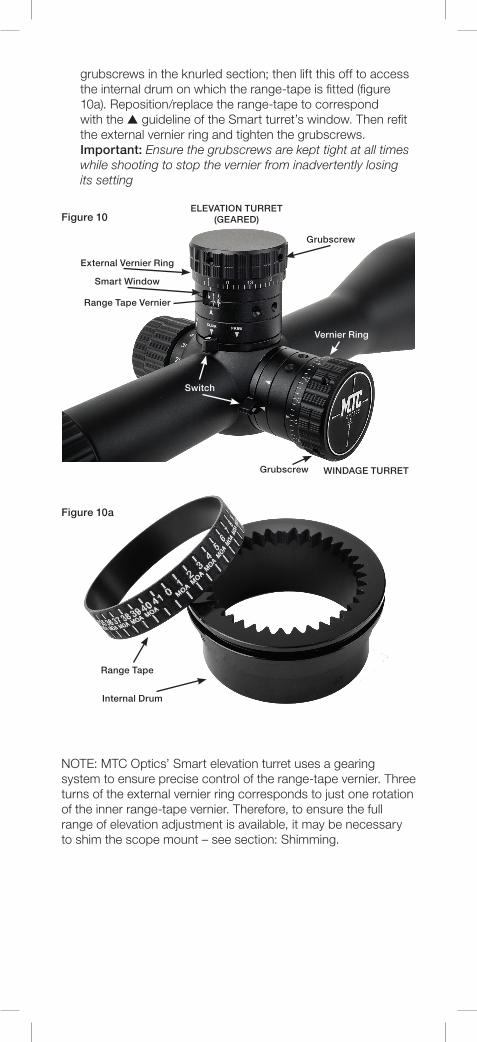
grubscrews in the knurled section; then lift this off to access the internal drum on which the range-tape is fitted (figure 10a). Reposition/replace the range-tape to correspond with the s guideline of the Smart turret’s window. Then refit the external vernier ring and tighten the grubscrews. Important: Ensure the grubscrews are kept tight at all times while shooting to stop the vernier from inadvertently losing its setting
NOTE: MTC Optics’ Smart elevation turret uses a gearing system to ensure precise control of the range-tape vernier. Three turns of the external vernier ring corresponds to just one rotation of the inner range-tape vernier. Therefore, to ensure the full range of elevation adjustment is available, it may be necessary to shim the scope mount – see section: Shimming.
ELEVATION TURRET (GEARED)Figure 10
Figure 10a
Grubscrew
WINDAGE TURRETGrubscrew
Vernier Ring
External Vernier Ring
Range Tape Vernier
Range Tape
Internal Drum
Smart Window
Switch

All MTC Optics Pro Series scopes are guaranteed for one year from date of purchase. The original purchaser can increase this to five years by registering their scope with MTC Optics within 30 days of original purchase. Registration can be made by either completing this form and returning it to the address below, or by registering online via www.mtcoptics.com. Either method requires a copy of the original receipt. (This guarantee does not cover user-generated damage.)
Date of Purchase:
Dealer Stamp/Details:
Dealer Signature:
Customer Name:
Customer Address:
Customer Email:
GUARANTEE REGISTRATION

www.mtcoptics.com | [email protected]
MTC Optics Ltd, Unit 3, Raleigh Hall Industrial Estate, Eccleshall. Staffordshire ST21 6JL United Kingdom.
While every effort is taken to ensure the accuracy of the information in this instruction manual, MTC Optics Ltd or their agents cannot be held responsible for errors or omissions. Products are continually updated and specification may change without notice. E&OE.
2018 v3