Pro Dunk Gold Owners Manual€¦ · rosion and repair be-fore using. ! During play, use ex-treme...
22
1 OWNER’S MANUAL Warning ! Do not slide, climb, or play on pole. ! Keep organic material away from pole base. Grass, litter, etc. could cause corrosion and /or deterioration. ! Check pole system twice a year for signs of corrosion (rust, pitting, and chipping). Remove rust and/or loose paint completely and repaint with exterior enamel paint. If rust has pene- trated through the steel anywhere, replace pole immediately. ! Check unit before each use for loose hardware, excessive wear, and signs of cor- rosion and repair be- fore using. ! During play, use ex- treme caution to keep players face away from the backboard, rim, and net. ! Wear a mouth guard when playing to avoid dental injuries. ! When adjusting height, keep hands and fingers away from mov- ing parts. ! During play, do not wear jewelry (rings, watches, necklaces, etc.). Objects may en- tangle in net. Pro Dunk® Gold Basketball System WELCOME TO THE FAMILY OF PRO DUNK® OWNERS Thank you for purchasing our basketball system. We try hard to ensure that our products are of high quality and free of manufacturing defects and of missing parts. However, if you have any problems with your basketball pole, such as a manufacturing defect or a missing part please contact us at the following: Toll Free: 1.888.600.8545 Pro Dunk® Hoops Web: www.produnkhoops.com 22047 Lutheran Church Rd. FAX: (281) 357-4822 Tomball, TX 77377 Please provide model number, serial number, and/or part number of the product and/or part when you call, write or email. These numbers can be found on the product, packaging, or on the back of the main pole. Purchase Parts: www.produnkhoops.com/parts Support: www.produnkhoops.com/support Installation Video: www.produnkhoops.com/video/installation.php Read this manual all the way through before starting to put up your system. Then read each step completely before beginning installation. www.Call811.com
Transcript of Pro Dunk Gold Owners Manual€¦ · rosion and repair be-fore using. ! During play, use ex-treme...
1
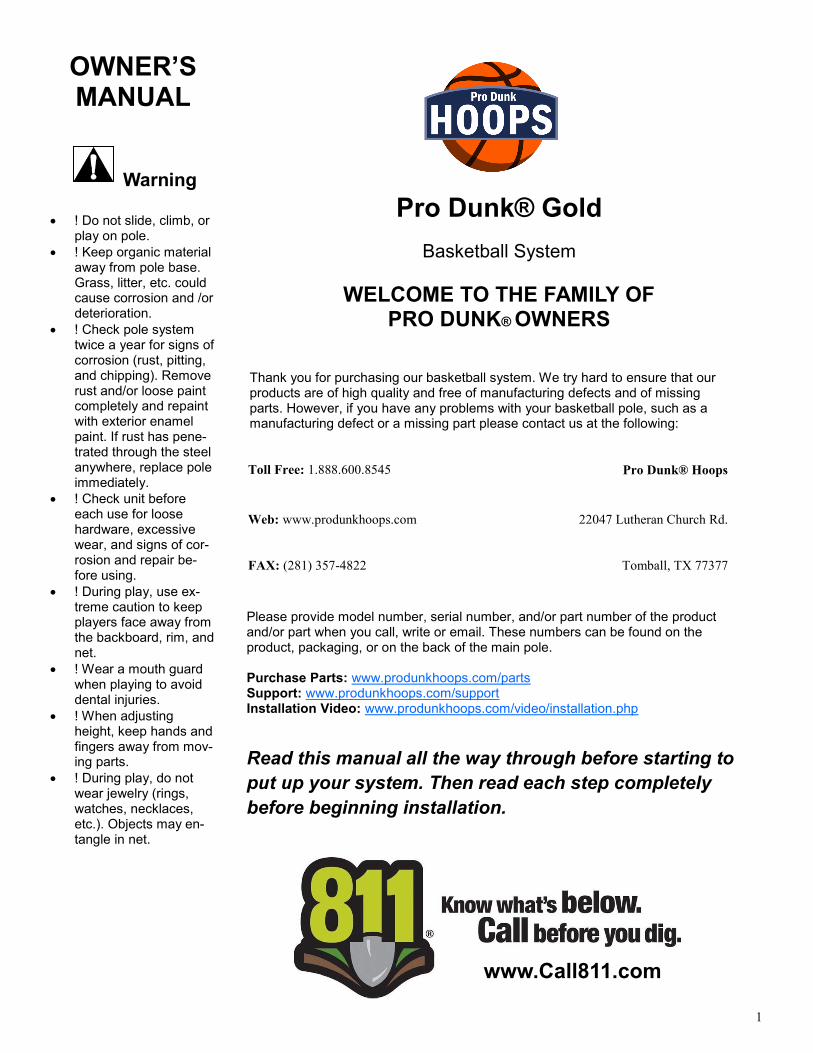
OWNER’S MANUAL
Warning
! Do not slide, climb, or play on pole.
! Keep organic material away from pole base. Grass, litter, etc. could cause corrosion and /or deterioration.
! Check pole system twice a year for signs of corrosion (rust, pitting, and chipping). Remove rust and/or loose paint completely and repaint with exterior enamel paint. If rust has pene-trated through the steel anywhere, replace pole immediately.
! Check unit before each use for loose hardware, excessive wear, and signs of cor-rosion and repair be-fore using.
! During play, use ex-treme caution to keep players face away from the backboard, rim, and net.
! Wear a mouth guard when playing to avoid dental injuries.
! When adjusting height, keep hands and fingers away from mov-ing parts.
! During play, do not wear jewelry (rings, watches, necklaces, etc.). Objects may en-tangle in net.
Pro Dunk® Gold
Basketball System
WELCOME TO THE FAMILY OF PRO DUNK® OWNERS
Thank you for purchasing our basketball system. We try hard to ensure that our products are of high quality and free of manufacturing defects and of missing parts. However, if you have any problems with your basketball pole, such as a manufacturing defect or a missing part please contact us at the following:
Toll Free: 1.888.600.8545 Pro Dunk® Hoops
Web: www.produnkhoops.com 22047 Lutheran Church Rd.
FAX: (281) 357-4822 Tomball, TX 77377
Please provide model number, serial number, and/or part number of the product and/or part when you call, write or email. These numbers can be found on the product, packaging, or on the back of the main pole. Purchase Parts: www.produnkhoops.com/parts Support: www.produnkhoops.com/support Installation Video: www.produnkhoops.com/video/installation.php
Read this manual all the way through before starting to
put up your system. Then read each step completely
before beginning installation.
www.Call811.com
2
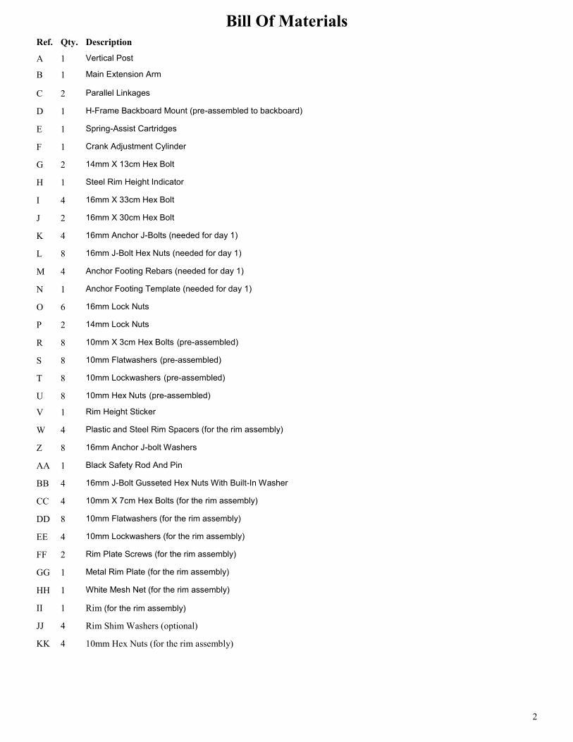
Ref. Qty. Description
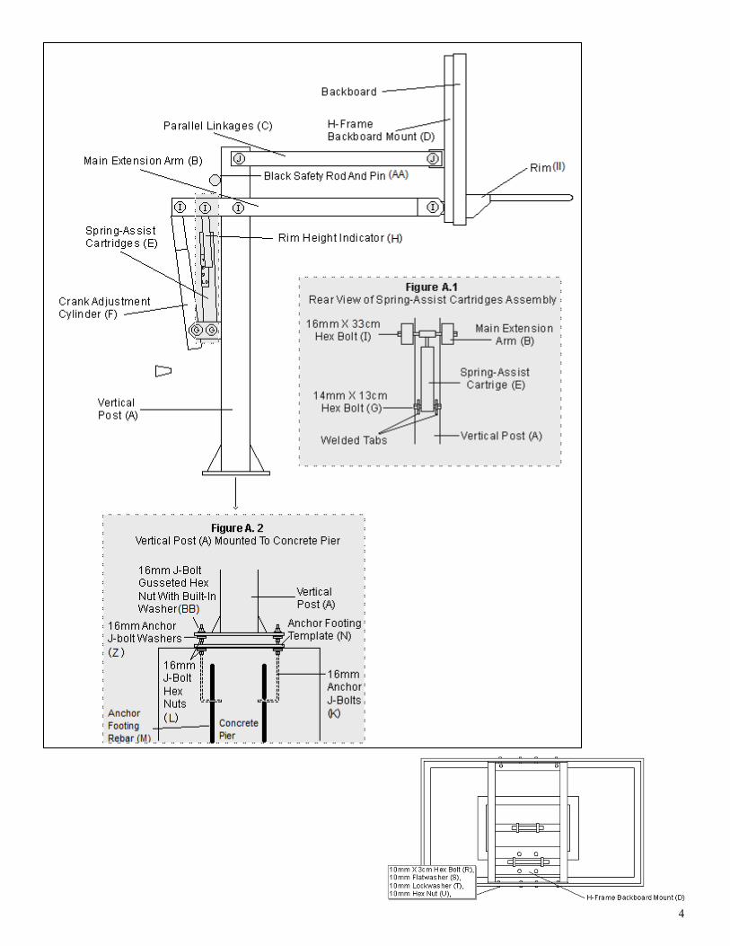
A 1 Vertical Post
B 1 Main Extension Arm
C 2 Parallel Linkages
D 1 H-Frame Backboard Mount (pre-assembled to backboard)
E 1 Spring-Assist Cartridges
F 1 Crank Adjustment Cylinder
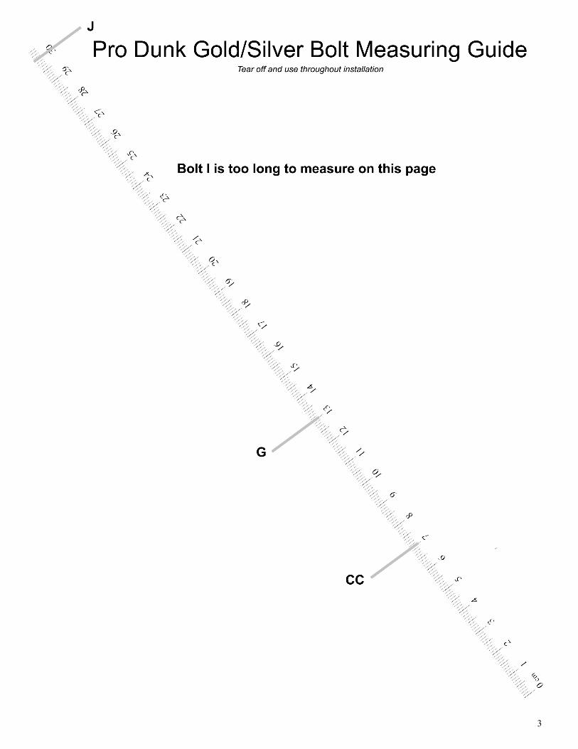
G 2 14mm X 13cm Hex Bolt
H 1 Steel Rim Height Indicator
I 4 16mm X 33cm Hex Bolt
J 2 16mm X 30cm Hex Bolt
K 4 16mm Anchor J-Bolts (needed for day 1)
L 8 16mm J-Bolt Hex Nuts (needed for day 1)
M 4 Anchor Footing Rebars (needed for day 1)
N 1 Anchor Footing Template (needed for day 1)
O 6 16mm Lock Nuts
P 2 14mm Lock Nuts
R 8 10mm X 3cm Hex Bolts (pre-assembled)
S 8 10mm Flatwashers (pre-assembled)
T 8 10mm Lockwashers (pre-assembled)
U 8 10mm Hex Nuts (pre-assembled)
V 1 Rim Height Sticker
W 4 Plastic and Steel Rim Spacers (for the rim assembly)
Z 8 16mm Anchor J-bolt Washers
AA 1 Black Safety Rod And Pin
BB 4 16mm J-Bolt Gusseted Hex Nuts With Built-In Washer
CC 4 10mm X 7cm Hex Bolts (for the rim assembly)
DD 8 10mm Flatwashers (for the rim assembly)
EE 4 10mm Lockwashers (for the rim assembly)
FF 2 Rim Plate Screws (for the rim assembly)
GG 1 Metal Rim Plate (for the rim assembly)
HH 1 White Mesh Net (for the rim assembly)
II 1 Rim (for the rim assembly)
JJ 4 Rim Shim Washers (optional)
KK 4 10mm Hex Nuts (for the rim assembly)
Bill Of Materials
3
4
5
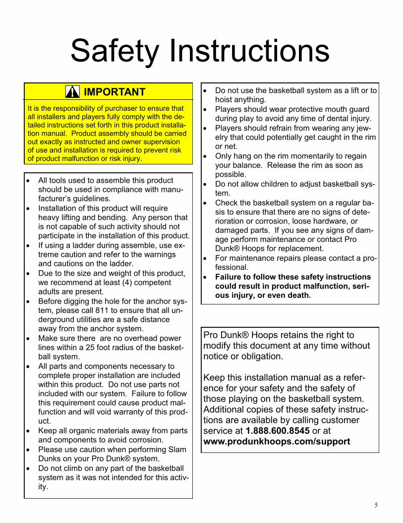
Safety Instructions
All tools used to assemble this product should be used in compliance with manu-facturer’s guidelines.
Installation of this product will require heavy lifting and bending. Any person that is not capable of such activity should not participate in the installation of this product.
If using a ladder during assemble, use ex-treme caution and refer to the warnings and cautions on the ladder.
Due to the size and weight of this product, we recommend at least (4) competent adults are present.
Before digging the hole for the anchor sys-tem, please call 811 to ensure that all un-derground utilities are a safe distance away from the anchor system.
Make sure there are no overhead power lines within a 25 foot radius of the basket-ball system.
All parts and components necessary to complete proper installation are included within this product. Do not use parts not included with our system. Failure to follow this requirement could cause product mal-function and will void warranty of this prod-uct.
Keep all organic materials away from parts and components to avoid corrosion.
Please use caution when performing Slam Dunks on your Pro Dunk® system.
Do not climb on any part of the basketball system as it was not intended for this activ-ity.
IMPORTANT
It is the responsibility of purchaser to ensure that all installers and players fully comply with the de-tailed instructions set forth in this product installa-tion manual. Product assembly should be carried out exactly as instructed and owner supervision of use and installation is required to prevent risk of product malfunction or risk injury.
Pro Dunk® Hoops retains the right to modify this document at any time without notice or obligation. Keep this installation manual as a refer-ence for your safety and the safety of those playing on the basketball system. Additional copies of these safety instruc-tions are available by calling customer service at 1.888.600.8545 or at www.produnkhoops.com/support
Do not use the basketball system as a lift or to hoist anything.
Players should wear protective mouth guard during play to avoid any time of dental injury.
Players should refrain from wearing any jew-elry that could potentially get caught in the rim or net.
Only hang on the rim momentarily to regain your balance. Release the rim as soon as possible.
Do not allow children to adjust basketball sys-tem.
Check the basketball system on a regular ba-sis to ensure that there are no signs of dete-rioration or corrosion, loose hardware, or damaged parts. If you see any signs of dam-age perform maintenance or contact Pro Dunk® Hoops for replacement.
For maintenance repairs please contact a pro-fessional.
Failure to follow these safety instructions could result in product malfunction, seri-ous injury, or even death.
6
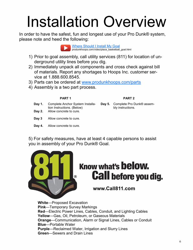
Installation Overview
5) For safety measures, have at least 4 capable persons to assist you in assembly of your Pro Dunk® Goal.
White—Proposed Excavation Pink—Temporary Survey Markings Red—Electric Power Lines, Cables, Conduit, and Lighting Cables Yellow—Gas, Oil, Petroleum, or Gaseous Materials Orange—Communication, Alarm or Signal Lines, Cables or Conduit Blue—Portable Water Purple—Reclaimed Water, Irrigation and Slurry Lines Green—Sewers and Drain Lines
www.Call811.com
In order to have the safest, fun and longest use of your Pro Dunk® system, please note and heed the following:
1) Prior to goal assembly, call utility services (811) for location of un-derground utility lines before you dig.
2) Immediately unpack all components and cross check against bill of materials. Report any shortages to Hoops Inc. customer ser-vice at 1.888.600.8545.
3) Parts can be ordered at www.produnkhoops.com/parts 4) Assembly is a two part process.
PART 1 PART 2
Day 1.
Complete Anchor System Installa-tion Instructions. (Below)
Day 5. Complete Pro Dunk® assem-bly instructions.
Day 2. Allow concrete to cure.
Day 3 Allow concrete to cure.
Day 4. Allow concrete to cure.
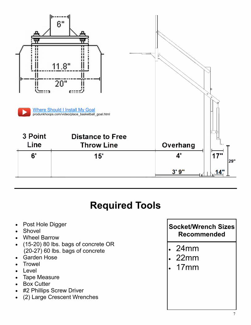
Where Should I Install My Goal produnkhoops.com/video/place_basketball_goal.html
7
Required Tools
Post Hole Digger Shovel Wheel Barrow (15-20) 80 lbs. bags of concrete OR (20-27) 60 lbs. bags of concrete Garden Hose Trowel Level Tape Measure Box Cutter #2 Phillips Screw Driver (2) Large Crescent Wrenches
24mm 22mm 17mm
Socket/Wrench Sizes Recommended
Where Should I Install My Goal produnkhoops.com/video/place_basketball_goal.html
8
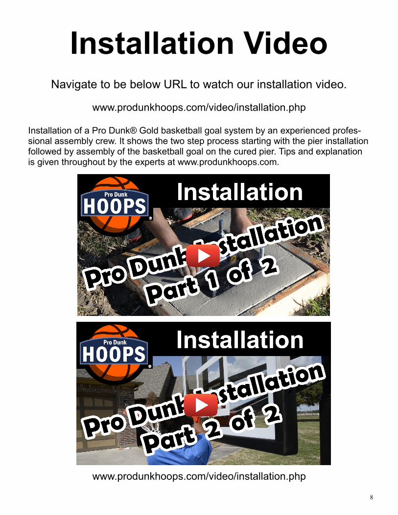
Installation Video
www.produnkhoops.com/video/installation.php
Installation of a Pro Dunk® Gold basketball goal system by an experienced profes-sional assembly crew. It shows the two step process starting with the pier installation followed by assembly of the basketball goal on the cured pier. Tips and explanation is given throughout by the experts at www.produnkhoops.com.
www.produnkhoops.com/video/installation.php
Navigate to be below URL to watch our installation video.
9
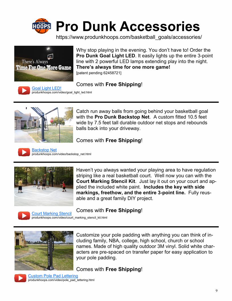
Pro Dunk Accessories
Catch run away balls from going behind your basketball goal with the Pro Dunk Backstop Net. A custom fitted 10.5 feet wide by 7.5 feet tall durable outdoor net stops and rebounds balls back into your driveway.
Comes with Free Shipping!
Goal Light LED! produnkhoops.com/video/goal_light_led.html
https://www.produnkhoops.com/basketball_goals/accessories/
Backstop Net produnkhoops.com/video/backstop_net.html
Court Marking Stencil produnkhoops.com/video/court_marking_stencil_kit.html
Why stop playing in the evening. You don’t have to! Order the Pro Dunk Goal Light LED. It easily lights up the entire 3-point line with 2 powerful LED lamps extending play into the night. There’s always time for one more game!
[patent pending 62458721]
Comes with Free Shipping!
Customize your pole padding with anything you can think of in-cluding family, NBA, college, high school, church or school names. Made of high quality outdoor 3M vinyl. Solid white char-acters are pre-spaced on transfer paper for easy application to your pole padding.
Comes with Free Shipping!
Haven’t you always wanted your playing area to have regulation striping like a real basketball court. Well now you can with the Court Marking Stencil Kit. Just lay it out on your court and ap-plied the included white paint. Includes the key with side markings, freethow, and the entire 3-point line. Fully reus-able and a great family DIY project.
Comes with Free Shipping!
Custom Pole Pad Lettering produnkhoops.com/video/pole_pad_lettering.html
10
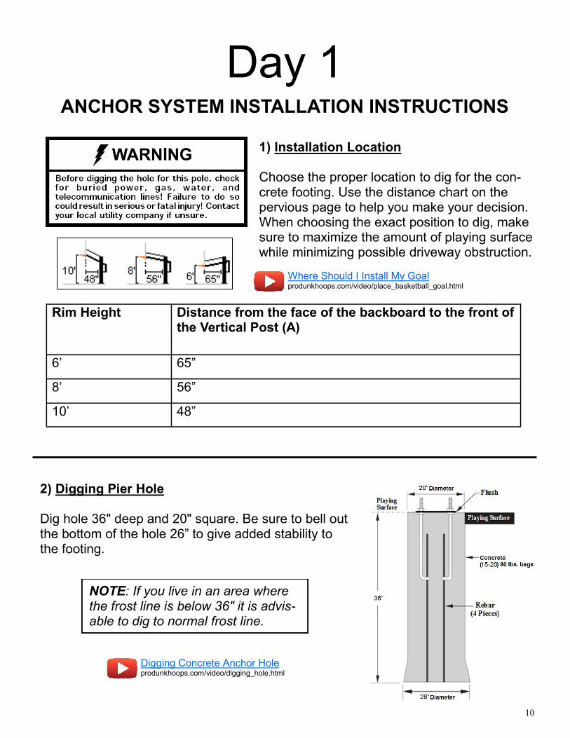
Day 1 ANCHOR SYSTEM INSTALLATION INSTRUCTIONS
1) Installation Location Choose the proper location to dig for the con-crete footing. Use the distance chart on the pervious page to help you make your decision. When choosing the exact position to dig, make sure to maximize the amount of playing surface while minimizing possible driveway obstruction.
Rim Height Distance from the face of the backboard to the front of the Vertical Post (A)
6’ 65”
8’ 56”
10’ 48”
2) Digging Pier Hole Dig hole 36" deep and 20" square. Be sure to bell out the bottom of the hole 26” to give added stability to the footing.
NOTE: If you live in an area where the frost line is below 36" it is advis-able to dig to normal frost line.
Where Should I Install My Goal produnkhoops.com/video/place_basketball_goal.html
Digging Concrete Anchor Hole produnkhoops.com/video/digging_hole.html
11
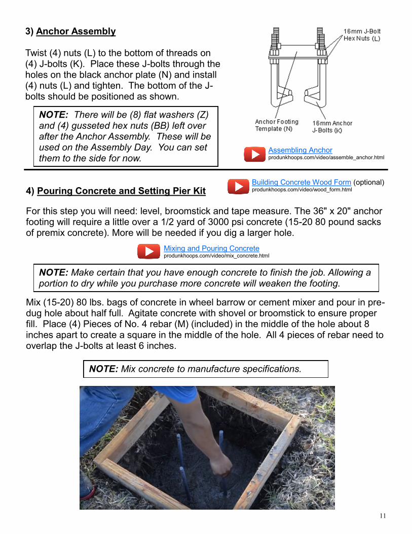
3) Anchor Assembly Twist (4) nuts (L) to the bottom of threads on (4) J-bolts (K). Place these J-bolts through the holes on the black anchor plate (N) and install (4) nuts (L) and tighten. The bottom of the J-bolts should be positioned as shown.
Mix (15-20) 80 lbs. bags of concrete in wheel barrow or cement mixer and pour in pre-dug hole about half full. Agitate concrete with shovel or broomstick to ensure proper fill. Place (4) Pieces of No. 4 rebar (M) (included) in the middle of the hole about 8 inches apart to create a square in the middle of the hole. All 4 pieces of rebar need to overlap the J-bolts at least 6 inches.
NOTE: Mix concrete to manufacture specifications.
NOTE: There will be (8) flat washers (Z) and (4) gusseted hex nuts (BB) left over after the Anchor Assembly. These will be used on the Assembly Day. You can set them to the side for now.
4) Pouring Concrete and Setting Pier Kit
For this step you will need: level, broomstick and tape measure. The 36" x 20" anchor footing will require a little over a 1/2 yard of 3000 psi concrete (15-20 80 pound sacks of premix concrete). More will be needed if you dig a larger hole.
NOTE: Make certain that you have enough concrete to finish the job. Allowing a portion to dry while you purchase more concrete will weaken the footing.
Building Concrete Wood Form (optional) produnkhoops.com/video/wood_form.html
Mixing and Pouring Concrete produnkhoops.com/video/mix_concrete.html
Assembling Anchor produnkhoops.com/video/assemble_anchor.html
12
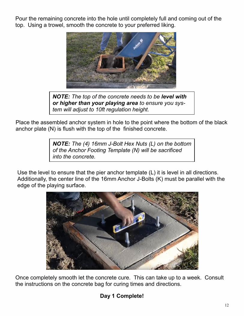
Use the level to ensure that the pier anchor template (L) it is level in all directions. Additionally, the center line of the 16mm Anchor J-Bolts (K) must be parallel with the edge of the playing surface.
Pour the remaining concrete into the hole until completely full and coming out of the top. Using a trowel, smooth the concrete to your preferred liking.
Place the assembled anchor system in hole to the point where the bottom of the black anchor plate (N) is flush with the top of the finished concrete.
NOTE: The (4) 16mm J-Bolt Hex Nuts (L) on the bottom of the Anchor Footing Template (N) will be sacrificed into the concrete.
Once completely smooth let the concrete cure. This can take up to a week. Consult the instructions on the concrete bag for curing times and directions.
Day 1 Complete!
NOTE: The top of the concrete needs to be level with or higher than your playing area to ensure you sys-tem will adjust to 10ft regulation height.
13
Day ~5
PRO DUNK® ASSEMBLY INSTRUCTIONS
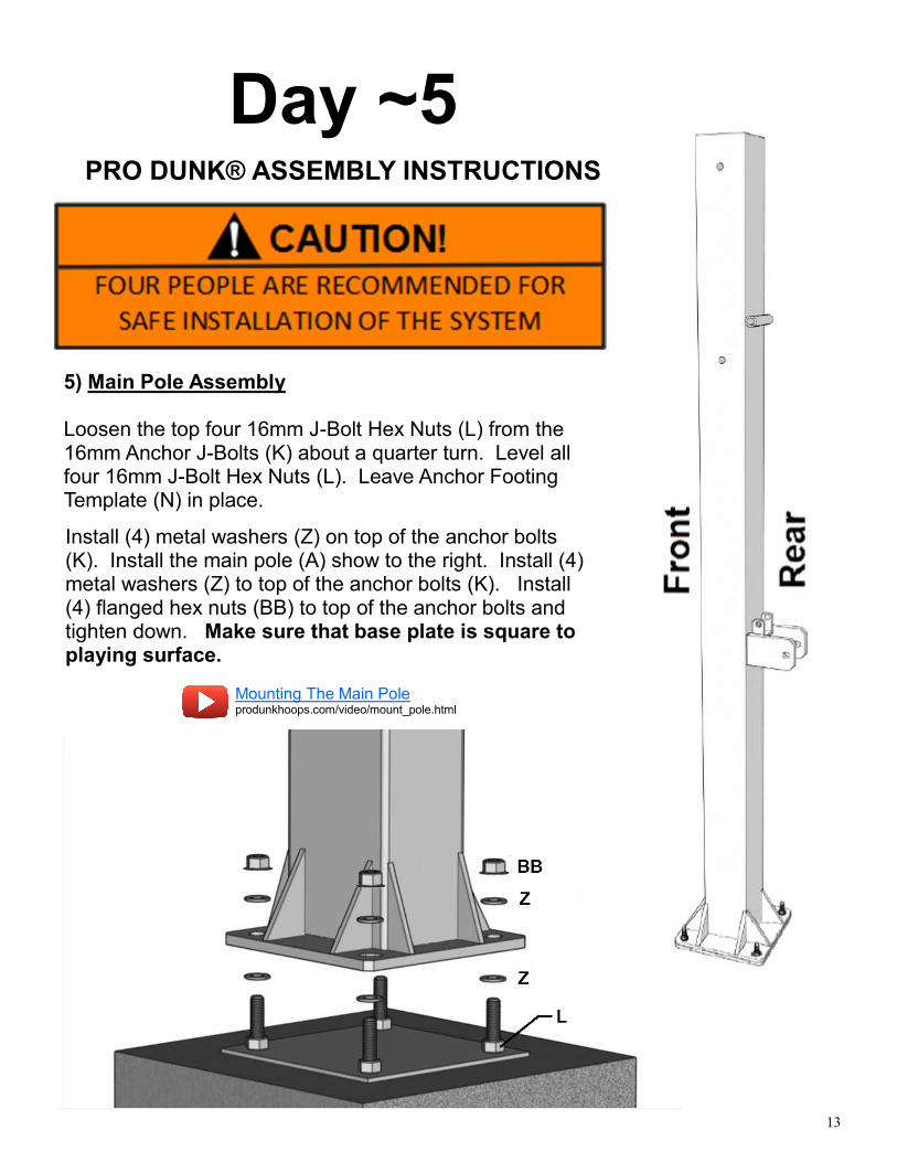
5) Main Pole Assembly Loosen the top four 16mm J-Bolt Hex Nuts (L) from the 16mm Anchor J-Bolts (K) about a quarter turn. Level all four 16mm J-Bolt Hex Nuts (L). Leave Anchor Footing Template (N) in place.
Install (4) metal washers (Z) on top of the anchor bolts (K). Install the main pole (A) show to the right. Install (4) metal washers (Z) to top of the anchor bolts (K). Install (4) flanged hex nuts (BB) to top of the anchor bolts and tighten down. Make sure that base plate is square to playing surface.
Mounting The Main Pole produnkhoops.com/video/mount_pole.html
14
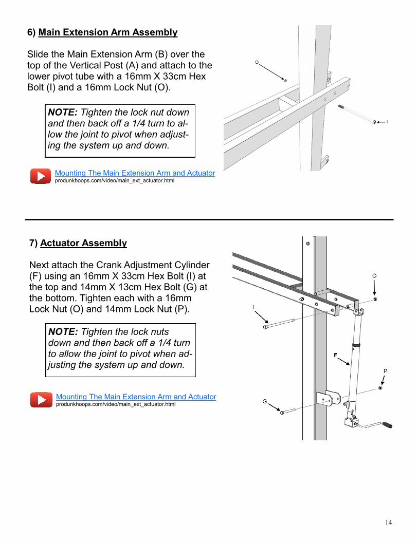
6) Main Extension Arm Assembly Slide the Main Extension Arm (B) over the top of the Vertical Post (A) and attach to the lower pivot tube with a 16mm X 33cm Hex Bolt (I) and a 16mm Lock Nut (O).
NOTE: Tighten the lock nut down and then back off a 1/4 turn to al-low the joint to pivot when adjust-ing the system up and down.
Mounting The Main Extension Arm and Actuator produnkhoops.com/video/main_ext_actuator.html
7) Actuator Assembly Next attach the Crank Adjustment Cylinder (F) using an 16mm X 33cm Hex Bolt (I) at the top and 14mm X 13cm Hex Bolt (G) at the bottom. Tighten each with a 16mm Lock Nut (O) and 14mm Lock Nut (P).
NOTE: Tighten the lock nuts down and then back off a 1/4 turn to allow the joint to pivot when ad-justing the system up and down.
Mounting The Main Extension Arm and Actuator produnkhoops.com/video/main_ext_actuator.html
15
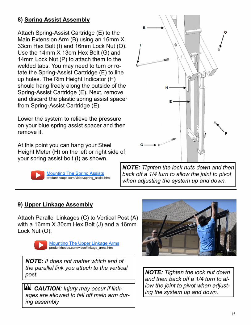
8) Spring Assist Assembly Attach Spring-Assist Cartridge (E) to the Main Extension Arm (B) using an 16mm X 33cm Hex Bolt (I) and 16mm Lock Nut (O). Use the 14mm X 13cm Hex Bolt (G) and 14mm Lock Nut (P) to attach them to the welded tabs. You may need to turn or ro-tate the Spring-Assist Cartridge (E) to line up holes. The Rim Height Indicator (H) should hang freely along the outside of the Spring-Assist Cartridge (E). Next, remove and discard the plastic spring assist spacer from Spring-Assist Cartridge (E). Lower the system to relieve the pressure on your blue spring assist spacer and then remove it. At this point you can hang your Steel Height Meter (H) on the left or right side of your spring assist bolt (I) as shown.
NOTE: Tighten the lock nuts down and then back off a 1/4 turn to allow the joint to pivot when adjusting the system up and down.
9) Upper Linkage Assembly Attach Parallel Linkages (C) to Vertical Post (A) with a 16mm X 30cm Hex Bolt (J) and a 16mm Lock Nut (O).
NOTE: It does not matter which end of the parallel link you attach to the vertical post.
CAUTION: Injury may occur if link-ages are allowed to fall off main arm dur-ing assembly
NOTE: Tighten the lock nut down and then back off a 1/4 turn to al-low the joint to pivot when adjust-ing the system up and down.
Mounting The Spring Assists produnkhoops.com/video/spring_assist.html
Mounting The Upper Linkage Arms produnkhoops.com/video/linkage_arms.html
16
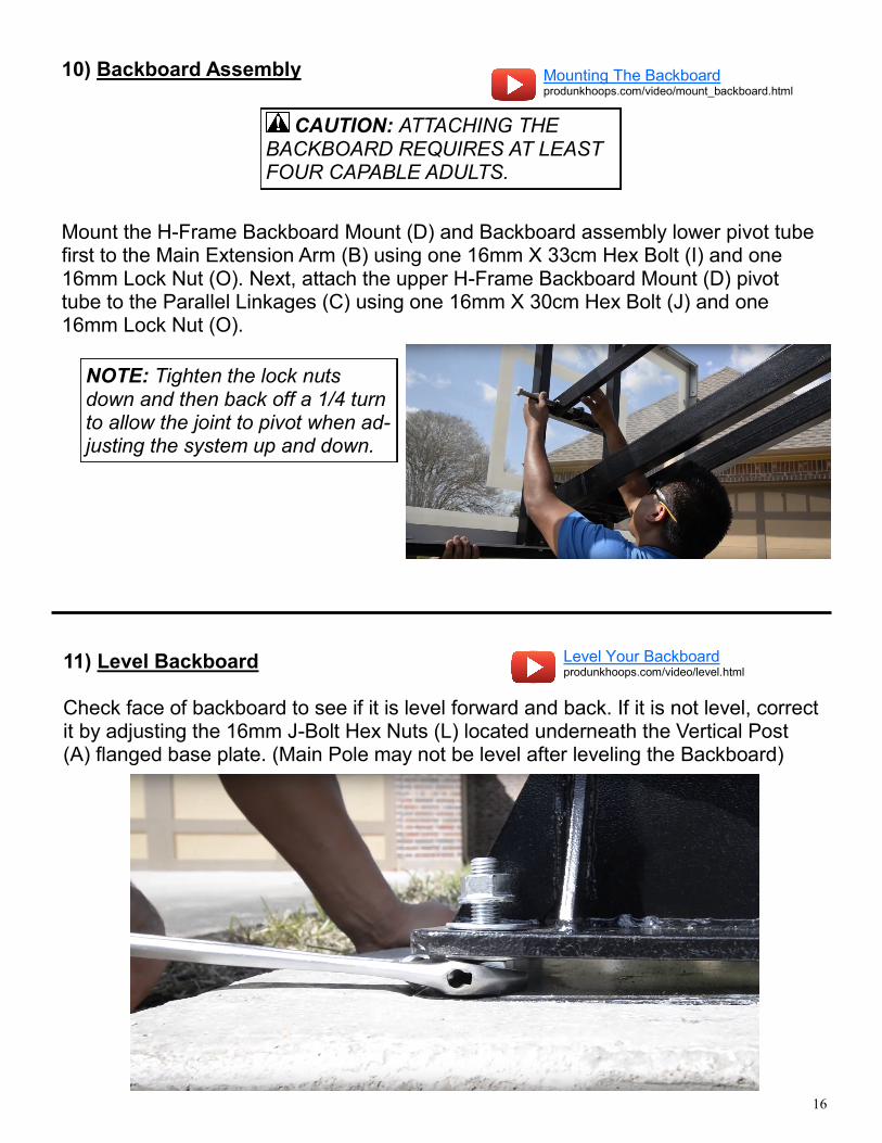
10) Backboard Assembly Mount the H-Frame Backboard Mount (D) and Backboard assembly lower pivot tube first to the Main Extension Arm (B) using one 16mm X 33cm Hex Bolt (I) and one 16mm Lock Nut (O). Next, attach the upper H-Frame Backboard Mount (D) pivot tube to the Parallel Linkages (C) using one 16mm X 30cm Hex Bolt (J) and one 16mm Lock Nut (O).
CAUTION: ATTACHING THE BACKBOARD REQUIRES AT LEAST FOUR CAPABLE ADULTS.
NOTE: Tighten the lock nuts down and then back off a 1/4 turn to allow the joint to pivot when ad-justing the system up and down.
11) Level Backboard Check face of backboard to see if it is level forward and back. If it is not level, correct it by adjusting the 16mm J-Bolt Hex Nuts (L) located underneath the Vertical Post (A) flanged base plate. (Main Pole may not be level after leveling the Backboard)
Mounting The Backboard produnkhoops.com/video/mount_backboard.html
Level Your Backboard produnkhoops.com/video/level.html
17
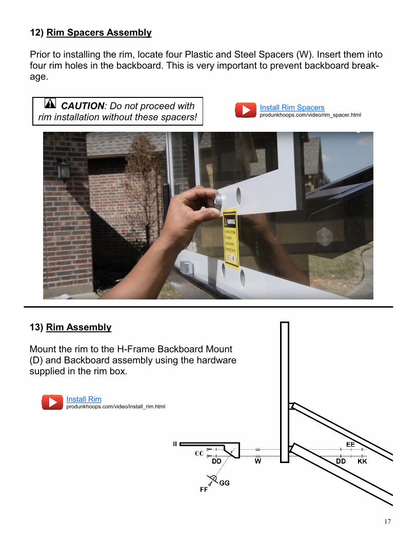
12) Rim Spacers Assembly Prior to installing the rim, locate four Plastic and Steel Spacers (W). Insert them into four rim holes in the backboard. This is very important to prevent backboard break-age.
CAUTION: Do not proceed with rim installation without these spacers!
Install Rim Spacers produnkhoops.com/video/rim_spacer.html
13) Rim Assembly Mount the rim to the H-Frame Backboard Mount (D) and Backboard assembly using the hardware supplied in the rim box.
Install Rim produnkhoops.com/video/install_rim.html
18
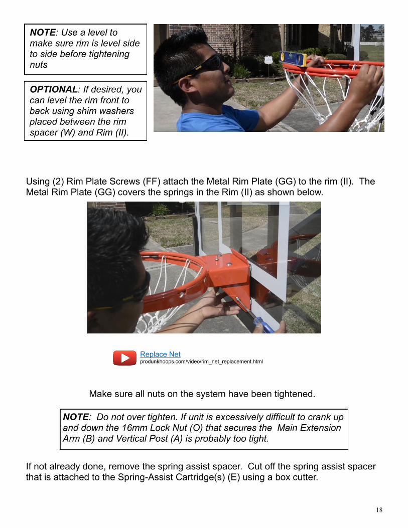
NOTE: Use a level to make sure rim is level side to side before tightening nuts
Make sure all nuts on the system have been tightened.
NOTE: Do not over tighten. If unit is excessively difficult to crank up and down the 16mm Lock Nut (O) that secures the Main Extension Arm (B) and Vertical Post (A) is probably too tight.
If not already done, remove the spring assist spacer. Cut off the spring assist spacer that is attached to the Spring-Assist Cartridge(s) (E) using a box cutter.
Using (2) Rim Plate Screws (FF) attach the Metal Rim Plate (GG) to the rim (II). The Metal Rim Plate (GG) covers the springs in the Rim (II) as shown below.
OPTIONAL: If desired, you can level the rim front to back using shim washers placed between the rim spacer (W) and Rim (II).
Replace Net produnkhoops.com/video/rim_net_replacement.html
19
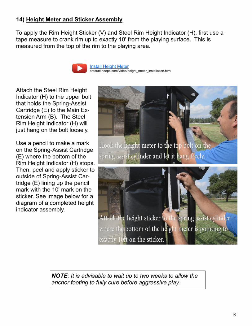
14) Height Meter and Sticker Assembly To apply the Rim Height Sticker (V) and Steel Rim Height Indicator (H), first use a tape measure to crank rim up to exactly 10' from the playing surface. This is measured from the top of the rim to the playing area.
Attach the Steel Rim Height Indicator (H) to the upper bolt that holds the Spring-Assist Cartridge (E) to the Main Ex-tension Arm (B). The Steel Rim Height Indicator (H) will just hang on the bolt loosely. Use a pencil to make a mark on the Spring-Assist Cartridge (E) where the bottom of the Rim Height Indicator (H) stops. Then, peel and apply sticker to outside of Spring-Assist Car-tridge (E) lining up the pencil mark with the 10' mark on the sticker. See image below for a diagram of a completed height indicator assembly.
NOTE: It is advisable to wait up to two weeks to allow the anchor footing to fully cure before aggressive play.
Install Height Meter produnkhoops.com/video/height_meter_installation.html
20
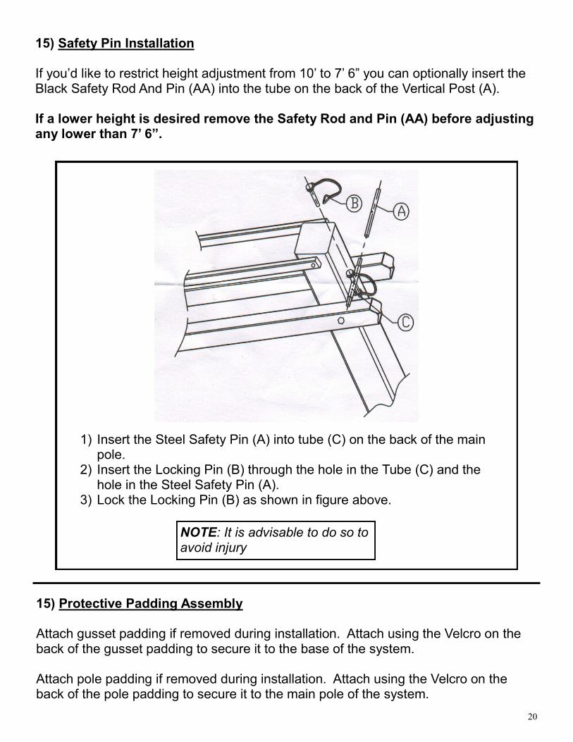
15) Safety Pin Installation If you’d like to restrict height adjustment from 10’ to 7’ 6” you can optionally insert the Black Safety Rod And Pin (AA) into the tube on the back of the Vertical Post (A). If a lower height is desired remove the Safety Rod and Pin (AA) before adjusting any lower than 7’ 6”.
NOTE: It is advisable to do so to avoid injury
1) Insert the Steel Safety Pin (A) into tube (C) on the back of the main pole.
2) Insert the Locking Pin (B) through the hole in the Tube (C) and the hole in the Steel Safety Pin (A).
3) Lock the Locking Pin (B) as shown in figure above.
15) Protective Padding Assembly Attach gusset padding if removed during installation. Attach using the Velcro on the back of the gusset padding to secure it to the base of the system. Attach pole padding if removed during installation. Attach using the Velcro on the back of the pole padding to secure it to the main pole of the system.
21
17) Routine System Inspection Before each use inspect the entire system for any signs of Loose nuts and bolts, any excessive wear and tear, any signs of rust or corrosion. If replacement parts are needed you can contact Pro Dunk® Hoops directly or navi-gate to www.produnkhoops.com/parts to purchase parts for your system. Only parts provided by Pro Dunk® Hoops should be used for repair. Not doing so could cause the system to fail resulting in injury or death and voids the limited lifetime warranty.
2-10-2018
17) Maintenance Like any piece of hardware proper maintenance is required. Several factors such as the en-vironment, organic materials, herbicides, pesticides, excessive use or misuse can eventually cause the basketball system to require maintenance. Failure to do so could result in system failure, property damage, or even personal injury. 1) All organic materials should be kept away from the system at all times. This will alleviate
any chance of rust penetrating the powder coated finish and causing structural damage. Examples: grass clippings, moisture, garbage, dirt, etc. 2) If you see any signs of rust on the system remove the loose paint, sand the area with a media grit sandpaper and apply outdoor enamel to the affected area. Suggested Touchup Paint: Rustoleum Semi-Gloss Black Enamel 3) To clean the backboard use a 100% cotton soft cloth with mild dishwashing liquid for soap and luke warm water. Rinse backboard with lukewarm water. Wash gently with a 100% Cot-ton soft cloth, lukewarm water and mild soap. Do not scrub. Rinse backboard with lukewarm water again. Dry with 100% cotton soft cloth. To minimize scratches and minor abrasions to your backboard 4) Never adjust the rim below 5’ or over 10’. Adjustments of the goal should be done under adult supervision. When attempting to slam dunk you should always wear a mouth guard to avoid dental injury. If safety pin (AA) is installed do not adjust the system below 7’ 6”. If a lower height is desired remove the safety pin (AA) and continue to adjust downward. 5) If installed in a public area it is suggested to lock the adjustment mechanism. You can purchase a pad lock to do this. Suggested Lock: Pro Dunk® Lock— 6) Replace Net Video—
Pro Dunk Lock produnkhoops.com/video/lock.html
Replace Net produnkhoops.com/video/rim_net_replacement.html

22
Hoops Inc. Pro Dunk® Limited Lifetime Warranty
Hoops Pro Dunk® basketball structural components are warranted to the original purchaser to be free from defects in material or workmanship for the duration of ownership by the original retail purchaser. The word “defects” is defined as imperfections that impair the use of the product. Warranty Fulfillment Merchandise must be shipped prepaid with a copy of proof of purchase to Hoops Inc. for examination to see whether it needs to be repaired or replaced. Any labor costs, travel expenses and any other changes involved in the removal, installation or replacement of the defective/repaired parts from/to your Hoops Pro Dunk® system will be your (the pur-chaser's) responsibility. Shipping charges for replaced or warranted merchandise being sent back to the customer must be prepaid by the customer in advance. If not, the replacement shipment will be sent out collect. Hoops Inc. re-serves the right to examine photographs or physical evidence of merchandise claimed to be defective, and to recover said merchandise, prior to authorization of warranty claims. What is not covered by this warranty This warranty does not cover defects or damage due to improper installation, shipping, handling, alteration, accidents, vandalism, weather conditions (rusting), exposure to corrosives, negligence, misuse (anything other than a type of basketball activity or related contact with the unit), scratching, scuffing or any event beyond the control of the Hoops Inc.. If unit is not maintained as stated in the user manual the warranty will be void. Liability Hoops Inc. shall not be liable for indirect, special, or consequential damages arising out of or in connection with the use or performance of the products or other damages with respect to any economical loss, loss of property, loss of enjoyment of use, costs of removal, installation or other consequential damages for breach of any expressed or im-plied warranty on these products. Guidelines Keep your proof of purchase (original retail purchaser). Without it, we will not be able to proceed with any warranty service. Call
1-888-600-8545 / Warranty Dept. Write
Hoops Inc. Attn: Warranty Dept 22047 Lutheran Church Rd. Tomball TX 77377
For the most up to date warranty information please navigate to www.produnkhoops.com.