Pro C900 Creo Color Server Technology, for Color...
155
User Guide English Color Controller C-80, Powered by Creo Color Server Technology, for Pro C900 Version 1.0 731-01701A-EN
Transcript of Pro C900 Creo Color Server Technology, for Color...

User GuideEnglish
Color Controller C-80, Powered byCreo Color Server Technology, forPro C900Version 1.0
731-01701A-EN

CopyrightEastman Kodak, 2009. All rights reserved.
This document is also distributed in Portable Document Format (PDF). You may reproduce the document fromthe PDF file for internal use. Copies produced from the PDF file must be reproduced in whole.
TrademarksThe Creo wordmark, the Creo logo, and the names of Creo branded products and services referred to in thisdocument are trademarks of Eastman Kodak Company.
Adobe, Acrobat, Adobe Illustrator, Distiller, Photoshop, PostScript, and PageMaker are registered trademarks ofAdobe Systems Incorporated.
Apple, AppleShare, AppleTalk, iMac, ImageWriter, LaserWriter, Mac OS, Power Macintosh, and TrueType areregistered trademarks of Apple Computer, Inc. Macintosh is a trademark of Apple Computer, Inc., registered inthe U.S.A. and other countries.
PANTONE, Hexachrome, PANTONE Hexachrome, PANTONE Goe, and PANTONE MATCHING SYSTEM arethe property of Pantone, Inc.
PEARL, PEARLsetter, PEARLhdp, PEARLdry, and PEARLgold are registered trademarks of Presstek, Inc.
FCC complianceCreo branded equipment referred to in this document complies with the requirements in part 15 of the FCC Rulesfor a Class A digital device. Operation of the Creo branded equipment in a residential area may causeunacceptable interference to radio and TV reception, requiring the operator to take whatever steps are necessaryto correct the interference.
Equipment recyclingIn the European Union, this symbol indicates that when the last user wishes to discard this product, it must besent to appropriate facilities for recovery and recycling. Contact your local Print On-Demand Solutionsrepresentative or refer to http://www.kodak.com/go/recycle for additional information on the collection andrecovery programs available for this product.
Limitation of liabilityThe product, software or services are being provided on an "as is" and "as available" basis. Except as may bestated specifically in your contract, Kodak, its subsidiaries, and affiliates expressly disclaim all warranties of anykind, whether express or implied, including, but not limited to, any implied warranties of merchantability, fitnessfor a particular purpose and non-infringement.
You understand and agree that, except as may be stated specifically in your contract, Kodak, its subsidiaries, andaffiliates shall not be liable for any direct, indirect, incidental, special, consequential or exemplary damages,including but not limited to, damages for loss of profits, goodwill, use, data or other intangible losses (even ifKodak has been advised of the possibility of such damages), resulting from: (i) the use or the inability to use theproduct or software; (ii) the cost of procurement of substitute goods and services resulting from any products,goods, data, software, information or services purchased; (iii) unauthorized access to or alteration of yourproducts, software or data; (iv) statements or conduct of any third party; (v) any other matter relating to theproduct, software, or services.
The text and drawings herein are for illustration and reference only. The specifications on which they are basedare subject to change. Kodak may, at any time and without notice, make changes to this document. Kodak, foritself and on behalf of its subsidiaries, and affiliates, assumes no liability for technical or editorial errors oromissions made herein, and shall not be liable for incidental, consequential, indirect, or special damages,including, without limitation, loss of use, loss or alteration of data, delays, or lost profits or savings arising fromthe use of this document.
www.creoservers.com/
Internal 731-01701A-EN

Revised 2009-04-23

Contents1 Getting started 1
Printing this guide....................................................................................................................................1System overview.....................................................................................................................................2
Professional Power Pack..................................................................................................................3Process Power Pack........................................................................................................................3
Overview of the Workspace....................................................................................................................3Overview of the Printer LCD display.......................................................................................................8Turning on the Color Controller C-80.....................................................................................................11Turning off the Color Controller C-80.....................................................................................................11
2 Setting up your computer for printing 13Setting up your computer overview.......................................................................................................13Setting up printing on a Windows computer..........................................................................................14
Adding a network printer to your Windows computer.....................................................................14Loading the Print Driver software for the first time......................................................................... 15Deactivating the Print Driver software............................................................................................16Removing the Print Driver software................................................................................................16Downloading fonts..........................................................................................................................17
Setting up printing in Mac OS................................................................................................................17Installing the Print Driver software in Mac OS................................................................................17Defining a printer with the Print Driver software in Mac OS........................................................... 18Removing the Print Driver software................................................................................................19Copying the PPD file for Mac OS...................................................................................................20Adding a network printer for Mac OS X using IP, SMB, or AppleTalk ............................................20
3 Calibration 23Calibration overview..............................................................................................................................23Creating a calibration table using the X-Rite i1 spectrophotometer......................................................24Mapping jobs to calibration tables.........................................................................................................27
4 Printing a file in Windows and Mac OS 29Printing a file to the Color Controller C-80.............................................................................................29Secure printing......................................................................................................................................29Using a hot folder to print......................................................................................................................31
5 Printing from the color server 33Importing and printing a job...................................................................................................................33Previewing and editing a PDF file......................................................................................................... 33Editing a job overview........................................................................................................................... 34Moving a page in a job..........................................................................................................................35Deleting a page from a job....................................................................................................................36Merging one or more pages into a job...................................................................................................36Replacing pages....................................................................................................................................37

Proofing the job.....................................................................................................................................37Assigning a color set to your job.....................................................................................................38
Secure printing overview.......................................................................................................................39
6 Managing jobs 41Resubmitting a job.................................................................................................................................41Job Reports...........................................................................................................................................41
Accounting Viewer overview ..........................................................................................................41Job Report overview.......................................................................................................................42
PDF2Go jobs.........................................................................................................................................43Exporting an RTP or PDL file as a PDF file....................................................................................43
7 Working with color server tools on your computer 45Creo Remote Site Manager...................................................................................................................45
Remote Site Manager overview.....................................................................................................45Activating remote tools...................................................................................................................45Installing the Remote Site Manager in Windows............................................................................46Adding Creo color servers to the Remote Site Manager ...............................................................47Viewing the printer status...............................................................................................................48Remote Workspace overview.........................................................................................................48
Using the Web Center...........................................................................................................................49Overview of the Web Center..........................................................................................................49Connecting to the Web Center.......................................................................................................49
Office Hot Folder tool............................................................................................................................50Installing the Office Hot Folder tool................................................................................................50Creating a hot folder.......................................................................................................................51Using the Office Hot Folder tool to print.........................................................................................51
Creo Color Server Job Ticket software.................................................................................................52Creo Color Server Job Ticket software overview...........................................................................52Language settings..........................................................................................................................52Installing the Creo Color Server Job Ticket software.....................................................................52Creating and managing job tickets.................................................................................................53
Easy VDP File Creator tool...................................................................................................................54Selecting an Easy VDP File Creator template................................................................................56Adding records manually to your variable data job.........................................................................58Adding records from a database to your variable data job.............................................................59Creating and printing the variable data job.....................................................................................60
8 Managing color 63Color tools overview..............................................................................................................................63Managing color and profiles .................................................................................................................63
Importing a destination profile........................................................................................................64Importing a source profile...............................................................................................................65
Mapping media using the Media and Color Manager tool.....................................................................66Managing calibration tables...................................................................................................................67
Calibrations window........................................................................................................................68Adding an entry to a calibration table.............................................................................................69
Managing spot colors............................................................................................................................70Adding a spot color.........................................................................................................................72Editing a spot color.........................................................................................................................73Deleting a spot color.......................................................................................................................73Printing a spot color chart...............................................................................................................73
vi Color Controller C-80, Powered by Creo Color Server Technology, for Pro C900

Spot color variations overview........................................................................................................74Protecting specific spot colors........................................................................................................77Defining an RGB color as a spot color...........................................................................................77Defining a gray color as a spot color..............................................................................................78Defining a CMYK color as a spot color...........................................................................................79
Color adjustment with the Gradation Tool ............................................................................................80Previewing a job.............................................................................................................................81Creating a new gradation table.......................................................................................................81Editing a gradation table.................................................................................................................82
Touching up an image...........................................................................................................................83
9 Production workflows 85Print using imposition............................................................................................................................85
Imposition overview........................................................................................................................85Previewing an imposition layout.....................................................................................................85Printing a business card job...........................................................................................................87Printing a saddle stitch job..............................................................................................................90Imposition Template Builder Tool....................................................................................................90
Print with exceptions.............................................................................................................................95Adding exceptions to your job........................................................................................................95Deleting exceptions from your job..................................................................................................97Dynamic page exceptions and setpagedevice commands.............................................................97Printing dynamic page exceptions..................................................................................................97
10 Variable data printing jobs 101Variable Data Printing jobs..................................................................................................................101About VDP document formats.............................................................................................................101
About Variable Print Specification................................................................................................102About PPML.................................................................................................................................103
Managing VDP elements.....................................................................................................................103Selecting to Cache Global VDP Elements....................................................................................103Archiving VDP elements...............................................................................................................104Retrieving VDP elements.............................................................................................................106Deleting VDP Elements................................................................................................................106
11 Job parameters 109Print tab in the Job Parameters window..............................................................................................109Imposition tab in the Job Parameters window.....................................................................................112Quality tab in the Job Parameters window.......................................................................................... 116Color tab in the Job Parameters window.............................................................................................119Photo touch-up tab in the Job Parameters window.............................................................................124Finishing tab in the Job Parameters window.......................................................................................125Exceptions tab in the Job Parameters window....................................................................................129Services tab in the Job Parameters window.......................................................................................130
12 Setting up your color server 135The Preferences window.....................................................................................................................135Setting up a virtual printer...................................................................................................................139
Virtual printers..............................................................................................................................139Adding and editing a virtual printer...............................................................................................139Removing a virtual printer.............................................................................................................140
Contents vii

Maintaining your settings.....................................................................................................................140Backing up the configuration........................................................................................................140Restoring the configuration...........................................................................................................141
13 Troubleshooting 143Job History window.............................................................................................................................143Aborting a job......................................................................................................................................144Alerts window......................................................................................................................................144Printing system messages..................................................................................................................145
viii Color Controller C-80, Powered by Creo Color Server Technology, for Pro C900

1 Getting started
Printing this guideChange the paper size to print this document on any printer.
1. Open the PDF file in Adobe Acrobat.2. From the File menu, select Print.
The Print dialog box appears.
3. Select the desired paper size, for example, A4 or letter.4. In the Page Scaling list, select Fit To Printable Area or Shrink
To Printable Area.
Note: The names in the Page Scaling list vary according to theversion of the Adobe Acrobat software.
5. Click OK.This document is printed to the selected paper size to your printer.

System overviewThe Color Controller C-80, Powered by Creo Color ServerTechnology, for Pro C900 is an on-demand prepress system thatuses advanced prepress technologies to drive the Pro C900.
The Color Controller C-80 enables you to print from computersrunning the Microsoft Windows operating system and Apple MacOS operating system software. Using raster image processor(RIP) technology, the Color Controller C-80 converts image files inpage-description language (PDL) formats—for example, AdobePostScript, PDF, and variable data printing formats—to a suitableready-to-print (RTP) format for direct high-quality digital printing.The Color Controller C-80 also streamlines the printing process byallowing you to print with preset workflows.
In combination with the printer, the Color Controller C-80 enablesyou to efficiently print flyers, brochures, pamphlets, dummycatalogs, short-run trials, and print-on-demand publications. Wheninstalled as a network printer with the Color Controller C-80, thepress prints at the full-rated speed.
The Color Controller C-80 combines RIP functionalities,automation, control tools, and special hardware developmentcapabilities with Windows-based architecture.
Hardware and software componentsThe Color Controller C-80 includes:
● hardware, including the interface board● Off-the-shelf hardware● A DVD-RW drive with DVD burning software● The following software:
❐ Color Controller C-80 software❐ Adobe Acrobat 9.0 and PDF 1.7❐ Enfocus PitStop Edit❐ Microsoft Internet Explorer 6
Supported formatsThe Color Controller C-80 supports the following file formats:
● PostScript (composite or pre-separated files) (levels 1, 2, and 3)● Adobe PDF (versions 1.2 through 1.7)● EPS● Creo VPS (Variable Print Specification)
2 Chapter 1—Getting started

● PPML (Personalized Print Markup Language)● PPML.zip● File formats from various prepress systems—for example,
Kodak Brisque and TIFF/IT software● CT, LW● JPEG● TIFF● Pre-separated formats
Professional Power PackThe Professional Power Pack includes the following features.
Note: This kit is optional. To activate the features in the softwareyou need to install the dongle that is supplied with the kit.
● Spot Variations● Progressive Printing● Enfocus PitStop LE● VDP Management Tool● Imposition Template Builder● Job Slug Line● Dynamic Exceptions (SPD)
Process Power PackThis kit includes the following features:
Note: This kit is optional. To activate these features in the softwareyou need to install the dongle included in the kit:
● Photo Touch-up● Parallel Rip
Overview of the WorkspaceWhen you start the Color Controller C-80 software the workspaceautomatically appears.
Professional Power Pack 3

The workspace contains different areas that enable you to monitoryour job during the process and print stages. In addition, theworkspace includes tools and options that enable you to fullycustomize and manage your server and jobs.
4 Chapter 1—Getting started

Workspace area Description
Toolbar
Consists of shortcut buttons for the Import window , Resource Center
, Calibration , Spot Color Editor , Gradation , and Alerts
Printer Status
The Printer Statuspane displays information about the current printer status—for example,Printing, Ready, Warming up.
The printer icon changes according to the configuration of the printerand the finishing devices connected.
Overview of the Workspace 5
Workspace area Description
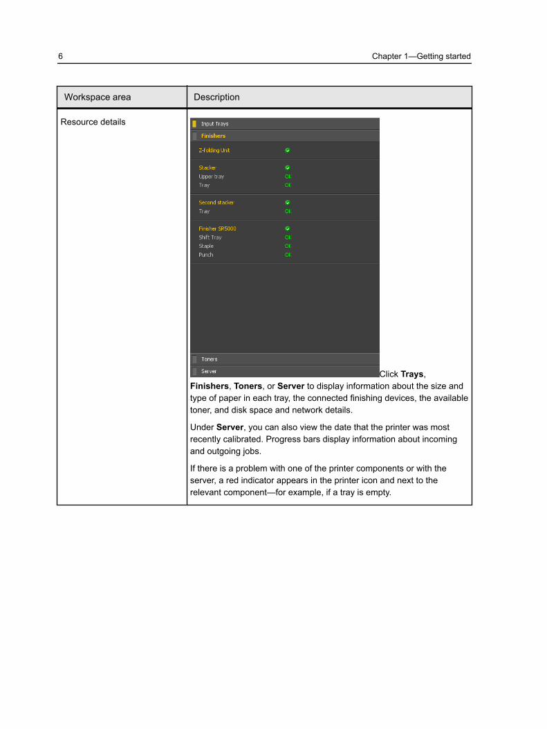
Resource details
Click Trays,Finishers, Toners, or Server to display information about the size andtype of paper in each tray, the connected finishing devices, the availabletoner, and disk space and network details.
Under Server, you can also view the date that the printer was mostrecently calibrated. Progress bars display information about incomingand outgoing jobs.
If there is a problem with one of the printer components or with theserver, a red indicator appears in the printer icon and next to therelevant component—for example, if a tray is empty.
6 Chapter 1—Getting started
Workspace area Description
Process and Process queues Consists of the Process Queue, which lists the files to be processed.After a file has been processed successfully, it moves either to the PrintQueue (the upper area) or to the Storage area.
I Indicates that the queue is ready for processing or printing.
Indicates that the queue is suspended. You will need to releasethe queue in order to process and print the jobs in this queue.
Note: When a queue is suspended you can open and edit the jobparameters of a job.
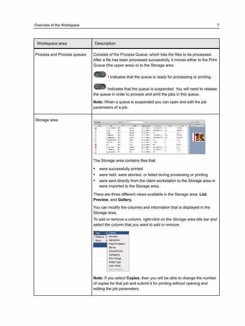
Storage area
The Storage area contains files that:
● were successfully printed● were held, were aborted, or failed during processing or printing● were sent directly from the client workstation to the Storage area or
were imported to the Storage area.
There are three different views available in the Storage area: List,Preview, and Gallery.
You can modify the columns and information that is displayed in theStorage area.
To add or remove a column, right-click on the Storage area title bar andselect the column that you want to add or remove.
Note: If you select Copies, then you will be able to change the numberof copies for that job and submit it for printing without opening andediting the job parameters.
Overview of the Workspace 7

Overview of the Printer LCD displayThe Printer LCD displays information from the Color ControllerC-80 and about the status of resources and connected finishingdevices.
The Printer LCD includes three main features:
● Printer application: Displays the printer and job status● Error and warning messages: Display errors and warnings
information depending on the job, for example, out of paper,unmatched media.
● Adjustment print function: Allows you to adjust the position of astaple, punch holes, and z-folding parameters.
Note: All the features on this application are controlled by touchingthe screen and not by using any of the buttons on the panel.
8 Chapter 1—Getting started

Option Description
Printer application
Job Name: Displays the name of the current job processing and printing onthe Color Controller C-80.
Note: Each cube on the progress bar represents 1/10 of the total job.
Job counting (200/3000 sheets): Displays the number of printed sheets fromthe total number of sheets in the job.
Abort: You can abort a job at any time from the start to the end of a job that isprinting.
Printer status: Displays the staus of the Printer, for example Printer is ready.
Note: The colors and messages are the same as appears on the ColorController C-80.
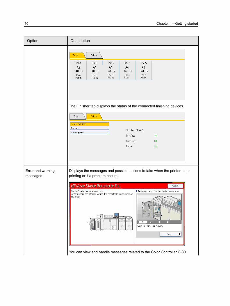
Finishers and Input Trays: The Tray tab displays the paper stock loaded in thetrays, the amount and orientation.
Overview of the Printer LCD display 9
Option Description
The Finisher tab displays the status of the connected finishing devices.
Error and warningmessages
Displays the messages and possible actions to take when the printer stopsprinting or if a problem occurs.
You can view and handle messages related to the Color Controller C-80.
10 Chapter 1—Getting started

Option Description
Turning on the Color Controller C-801. Turn on the monitor.2. Open the front panel of the Color Controller C-80, and push the
power control button.
The power indicator on the front panel lights up, and theWindows operating system logon screen appears.
The Color Controller C-80 splash screen appears, followed by theworkspace.
Note: If the workspace does not automatically appear, open theapplication from the Windows Start menu. By default, you canopen the workspace without logging on each time. If you wanteach user to log on, clear the Auto Log On checkbox in thePreferences window, and then assign each user an access leveland password.
Turning off the Color Controller C-801. From the File menu in the workspace, select Exit.
A confirmation message appears.
Turning on the Color Controller C-80 11

2. Click Yes.The Color Controller C-80 software closes. This may take a fewminutes.
Note: If you move the cursor over the server icon on thetaskbar, the following tooltip appears: Color Server is ShuttingDown. Please Wait.
3. Verify that the Color Controller C-80 icon does not appear onthe taskbar.
4. From the Windows Start menu, select Shut Down, and clickOK.
5. When the Windows shutdown is complete, turn off the monitor.
12 Chapter 1—Getting started

2 Setting up yourcomputer for printing
Setting up your computer overviewPrinting MethodsSome methods for printing with the Color Controller C-80:
● Submit the job to one of the Color Controller C-80 virtualprinters. The job is spooled and then processed or printed(according to the selected job flow of the virtual printer). If youuse this method, you can print from any software—for example,Microsoft Word—and use any file format from any Windows andMac.
● Drag the job to a hot folder. The job is spooled and processed orprinted (according to the selected job flow of the correspondingvirtual printer). If you use the hot folder method, you can printmost PDL files—for example, PostScript, PDF, EPS, VariablePrint Specification, and PPML.
Network printersTo print your file using a Color Controller C-80 virtual printer, youfirst need install the virtual printer as a network printer on yourcomputer.
After you install a network printer on your computer, you will beable to submit files for printing. The network printers are installedby default with the Print Driver software. You can change thedefault settings of the network printer to use the PPD parametersinstead of the Print Driver software.
The Color Controller C-80 supports printing from the followingoperating systems:
● Mac OS X (AppleTalk and TCP/IP )● Windows 2000, Windows XP, Windows Vista, Windows Server
2003, and Windows Server 2008
The Color Controller C-80 provides default network printers,referred to here as virtual printers.
A virtual printer contains preset workflows that are automaticallyapplied to all print jobs processed with that virtual printer. Thedefault virtual printers are published on the network with specificparameters set for processing and printing.

The default virtual printers are:● Process
Files sent to this printer are automatically processed and storedin ready-to-print (RTP) format in the Storage area. Later, youcan submit an RTP job for printing, or change the parameters ofthe job and resubmit it for processing or printing.
Files sent to this printer are automatically processed andimmediately sent to the press for printing.
● Store
Files sent to this printer are spooled to the Storage area andwait until you submit them for processing and printing. The filesremain in PDL format (such as PS, PDF, and PPML).
Print Driver softwareUse the Print Driver software to set job parameters when you aresubmitting a job to the Color Controller C-80 from any applicationin your computer. The Print Driver software is automaticallyinstalled on a Windows computer when you set up a network printer.
Note: On a Mac computer, you must install the Print Driversoftware manually.
In the Print Driver window, you can perform the following actions:● Define or change job parameters regardless of whether your
computer is connected to the server● Lock a job● Save a set of parameters. Sets are useful when you want to
print different jobs with the same parameters, or if you want toreprint a job.
● Retrieve a saved set of parameters● Check the status of the printer● Define PostScript parameters for the job● Preview imposition layout
Setting up printing on a Windows computer
Adding a network printer to your Windows computerTo print from a Windows computer, you first need to add a ColorController C-80 virtual printer to your client workstation.
Tip: A shortcut for setting up a printer is to locate the ColorController C-80 in My Network Places, and then double click on
14 Chapter 2—Setting up your computer for printing

the network printer you want to install. The network printer isautomatically installed on your computer and appears in the list ofprinters.
1. From the Start menu, select Settings > Printers and Faxes.The Printers and Faxes window appears.
2. In the Printer Tasks area, select Add a printer.
Note: Your computer might have slightly different wording fromwhat appears in this task.
The Add Printer Wizard appears.3. Select Next.4. Select A network printer, or a printer attached to another
computer, and then click Next.5. Select Browse for a printer, and click Next.6. Find the Color Controller C-80, and double-click it to display the
list of network printers.7. Select the desired printer, and click Next.8. When a message appears, click Yes.9. Select one of the following:
● Yes if you want to set this printer as the default printer onyour computer.
● No if you don't want to set the printer as the default printeron your computer.
10.Click Next.11.Click Finish to close the wizard.
The Color Controller C-80 network printer is added to your printerlist. In addition, the Print Driver software and PPD file areautomatically installed.
Loading the Print Driver software for the first timeRequirements:
A network printer must be defined on your computer.
Load the Print Driver software after installing a network printer sothat the Color Controller C-80 will be ready for printing.
1. Open a file with its corresponding application—for example,open a PDF file in Adobe Acrobat.
2. From the File menu, select Print.The Print dialog box appears.
3. Select one of the network printers—for example, Print and clickProperties.
A message tells you that the software is loading.
Loading the Print Driver software for the first time 15
Note: This process may take a few minutes.
The job parameters window appears.4. Close the job parameters window and printer Print Dialog box
to complete the installation of the Print Driver.
The network printer is set up for printing using the Print Driversoftware.
See also:Print tab in the Job Parameters window on page 109Imposition tab in the Job Parameters window on page 112Quality tab in the Job Parameters window on page 116Color tab in the Job Parameters window on page 119Finishing tab in the Job Parameters window on page 125Services tab in the Job Parameters window on page 130
Deactivating the Print Driver softwareDeactivate the Print Driver software if you want to access the PPDfile parameters. The Print Driver software is active by default.
1. From the Windows Start menu, select Settings > Printersand Faxes.
2. Right-click the printer icon of the network printer you want todeactivate the Print Driver, and select Properties.
3. Click the Print Driver tab.4. In the Enable enhanced user interface, list select off.5. Click Apply.6. Click OK.
Removing the Print Driver softwarePerform this procedure if you need to upgrade to a later version ofthe Print Driver software or if you want to install the Print Driversoftware for a printer with a different name.
Requirements:
All applications must be closed.
1. From the Windows Start menu, select Settings > Printersand Faxes.
2. Right-click the network printer that you want to remove, andselect Delete.
3. In the Printers and Faxes window, from the File menu, selectServer Properties.
16 Chapter 2—Setting up your computer for printing
4. In the Print Server Properties dialog box, click the Drivers tab.5. Select the appropriate printer, and click Remove.
The driver is removed.6. From the Windows Start menu, select Run.7. In the Open box, type \\, followed by the host name or IP
address of the server, and click OK.The server window opens.
8. Navigate to D:\Utilities\PC Utilities\Driver Extension.9. Perform one of the following steps:
● If you are using Windows XP, double-click● If you are using Windows Vista, right-click
Creo_Driver_Uninstaller.exe, and select Run asAdministrator.
The Print Driver software is removed.
Downloading fontsUse the HF_Fontdownloader hot folder, located in D:\HotFold-ers, to install new or missing fonts to the Color Controller C-80fonts directory.
The HF_Fontdownloader hot folder can be used with thefollowing operating systems:
● Windows Vista● Windows XP● Windows 2000● Windows Server 2008● Windows Server 2003● Mac OS X
Drag the required fonts from the computer to the HF_Fontdown-loader hot folder.
Setting up printing in Mac OS
Installing the Print Driver software in Mac OSDuring the installation of the Print Driver software, the PPD file isautomatically copied to your computer. In versions earlier thanMac OS 10.4, you must copy the PPD manually.
1. From the Go menu, select Connect to Server.
Downloading fonts 17

2. In the Server Address box, type your server address, and clickConnect.
3. In the Connect as area, select Guest.4. Click Connect.5. Select Utilities and click OK.6. Select the Mac Utilities folder.7. Double-click the C80CREO_ColorServerPrintDriverInstal-
ler.dmg file.The Welcome screen appears.
8. Click Continue.9. In the message window, click Continue.10.In the Software License Agreement window, click Continue.11.Click Agree to agree to the terms and continue with the
installation procedure.12.In the Select Destination area, select the destination volume
in which you want to install the Print Driver software, and clickContinue.
13.Click Upgrade.14.Type your login name (if necessary) and password, and click
OK.15.Click Close.
The Print Driver software and PPD are installed.
Note: If you deactivate the Print Driver software, you can still usethe PPD because it has been installed already.
Defining a printer with the Print Driver software in Mac OSRequirements:
The following information must be available:
● IP address and computer name of your Color Controller C-80
● Name of the network printer that you want to use with the PrintDriver software
1. On your Mac computer, open the System Preferences windowand double-click Print & Fax.
2. In the Print & Fax window, click the add (+) button.
Note: You can also define your printer using the Default option.3. In the Add Printer window, enter the following information:
● In the Address box, type the address of your server.
18 Chapter 2—Setting up your computer for printing

● In the Queue box, type the name of the network printer thatyou want to use with the Print Driver software.
● In the Name box, type a name for the printer.
● In the Print Using list, select Other.4. Navigate to Library / Printers / PPDS / Contents / Resour-
ces / en.lproj, select either Europe_A4 or US_Letter, andthen select the C80CREO.ppd.
5. Click Open.6. Click Add.7. Close the Print & Fax window.
The network printer is defined with the PPD file.8. In the Print & Fax window, double-click the network printer.9. Click Utility.10.In the Enable Enhanced User Interface list, make sure that
On is selected.11.In the Server Hostname box, type the IP address of the server.12.Click Apply.
Removing the Print Driver softwarePerform this procedure if you need to upgrade to a later softwareversion of the Print Driver software.
Requirements:
All applications must be closed.
1. Open the System Preferences window, and double-click Print& Fax.
2. In the Print & Fax window, select the network printer that youwant to remove.
3. Click delete (-), and then click OK.4. Navigate to Library / Printers / Creo_Color_Server_Tools,
and delete the Creo_Color_Server_Tools folder.5. Navigate to Library / Receipts folder, and delete all of the files.
The Print Driver software is removed. You can now upgrade thePrint Driver software.
Note: You will need to reinstall the network printers that youremoved after you have upgraded the software.
Removing the Print Driver software 19
Copying the PPD file for Mac OSCopy the PPD file in order to add a network printer to your Maccomputer.
Note: If you install the Print Driver software, the PPD file isautomatically copied.
1. From the Go menu, select Connect to Server.2. Locate the desired Color Controller C-80 in the network and
then double-click it.3. In the Connect to Server dialog box, select Guest.4. Click Connect.5. Select the Utilities volume, and click OK.6. On the desktop, double-click the Utilities volume icon.7. Double-click the PPD folder.8. Double-click the desired language folder.9. Browse to the desired paper type folder Mac OSX > Europe-
A4 or US-Letter.10.Select the C80CREO.ppd file.
For best results, copy the PPD file by dragging it to thespecified folder in your local disk. To do this, open anotherFinder window.
11.From the Go menu, select Computer.12.Click your disk icon, and locate the required folder—for
example, Library\Printers\PPDs\Contents\Resources.13.Select the desired language folder—for example, en.lproj for
English.14.Select either the Europe_A4 or US_Letter folders.15.Drag theC80CREO.ppd file to the folder.
Adding a network printer for Mac OS X using IP, SMB, orAppleTalk
Requirements:
To print from a Macintosh computer, you first need to add a ColorController C-80 virtual printer to your computer.
Note: Before you add one of the network printers make sure the C80CREO.ppd is located in the \Library\Printers\PPDs\Contents\Resources\en.lproj folder on your Macintosh computer.
1. From the Go menu, select Applications.
20 Chapter 2—Setting up your computer for printing

2. Open the Utilities folder and then double-click Printer SetupUtility.
3. Click the Add Printer button.4. Select either Default Browser or IP Printer.5. Browse to the Color Controller C-80 network printer (if you are
defining an IP printer, enter the Color Controller C-80 IPaddress or host name, and the exact name of the printer towhich you want to print—for example, <server_name>_Print).
6. In the Printer Using list, select Other.7. Browse to the folder to which you copied the C80CREO.ppd file
and then select it.8. Click Open to assign the C80CREO.ppd file to the selected
network printer.9. Click Add to add the new printer to the printer list.
You have successfully installed a network printer for the ColorController C-80 and are ready to start printing.
Setting up printing in Mac OS 21

22 Chapter 2—Setting up your computer for printing

3 Calibration
Calibration overviewObtaining the most satisfactory print quality on your printerdepends on a number of issues. One of the most important issuesis steady toner density. Toner density is affected by many factorssuch as heat, humidity, and service settings. Toner density alsotends to vary over time. Such variations cannot be totallyeliminated, but you can perform the calibration process tocompensate for them.
The calibration process consists of creating calibration tables thatare mapped to a specific media type, paper weight, and screeningmethod.
You create calibration tables using the Calibration wizard. TheCalibration wizard guides you through printing a color chart,scanning the streams of color patches in the color chart, andcreating a calibration table based on the scanned measurements.
The Color Controller C-80 uses the data in this table tocompensate for the differences between the the actual, measureddensity level, and the target level, the target density.
You should create calibration tables in the following instances:
● When you use a new paper stock● When prints show “color casts”● After machine maintenance or hardware changes● If there are drastic ambient changes (temperature and humidity)● Every 24 hours, to compensate for potential variations in toner
density

Creating a calibration table using the X-Rite i1spectrophotometer
Requirements:
● Your spectrophotometer must be connected to the USB port onthe Color Controller C-80.
● Install the driver when prompted for the first time connecting thedevice to the Color Controller C-80. Refer to thespectrophotometer product documentation for more information.
● Make sure that your spectrophotometer is calibrated by placingthe spectrophotometer on its plate.
● Print a reference job and use the same media and screen typeon which you will print the final job.
● Make sure that the Print Queue is not suspended and is readyfor printing.
1. From the Tools menu, select Calibration or select thecalibration icon from the toolbar .
2. The first step is to select the media type, weight, tray andscreening that you want to use for this calibration table.
3. In the Screening list, select the type of screen that you want touse.
24 Chapter 3—Calibration
4. In the Number of copies box, enter the number of copies youwant to print.
Note: It is recommended that you print at least 25 copies of thecalibration chart, and then use one of the last copies printed.
5. Click Print.The calibration chart prints.
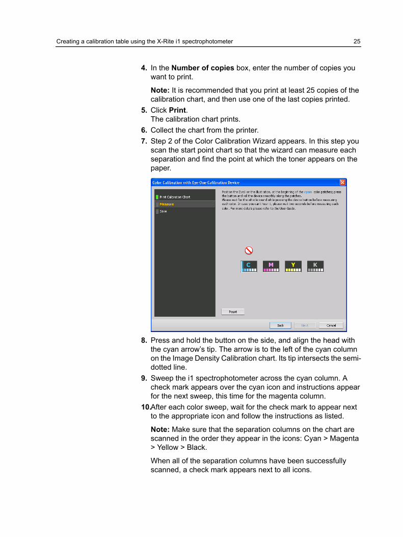
6. Collect the chart from the printer.7. Step 2 of the Color Calibration Wizard appears. In this step you
scan the start point chart so that the wizard can measure eachseparation and find the point at which the toner appears on thepaper.
8. Press and hold the button on the side, and align the head withthe cyan arrow’s tip. The arrow is to the left of the cyan columnon the Image Density Calibration chart. Its tip intersects the semi-dotted line.
9. Sweep the i1 spectrophotometer across the cyan column. Acheck mark appears over the cyan icon and instructions appearfor the next sweep, this time for the magenta column.
10.After each color sweep, wait for the check mark to appear nextto the appropriate icon and follow the instructions as listed.
Note: Make sure that the separation columns on the chart arescanned in the order they appear in the icons: Cyan > Magenta> Yellow > Black.
When all of the separation columns have been successfullyscanned, a check mark appears next to all icons.
Creating a calibration table using the X-Rite i1 spectrophotometer 25
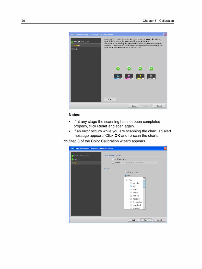
Notes:
● If at any stage the scanning has not been completedproperly, click Reset and scan again.
● If an error occurs while you are scanning the chart, an alertmessage appears. Click OK and re-scan the charts.
11.Step 3 of the Color Calibration wizard appears.
26 Chapter 3—Calibration

12.To save the calibration table, do one of the following:
● Select As default name to automatically name the calibrationtable using the screening method, meda type, and date.
● Select Save as to type your own name.
Note: It is strongly recommended that you include the mediatype, weight, and screening method in the calibration table filename.
13.Click Finish.
Mapping jobs to calibration tablesWhen you create a calibration table, the calibration table is basedon the media type, paper weight, and screening method that youselected during the calibration process. Any job that has thespecific media type, paper weight, and screening method that youselected, will automatically be mapped or linked to this calibrationtable.
In the Job Parameters window, under Color > Calibration, theLinked option is selected by default.
When you send your job to print, because the calibration table islinked to the job, it is automatically used when the job is printed.
Mapping jobs to calibration tables 27

28 Chapter 3—Calibration

4 Printing a file inWindows and Mac OS
Printing a file to the Color Controller C-80Requirements:
A network printer must be defined on your Windows and Maccomputer.
This task describes how to print from a Windows computer, andcan also be followed for printing from a Mac.
1. Open a file with its corresponding application—for example,open a PDF file in Adobe Acrobat.
2. From the File menu, select Print.3. In the Name list, select the desired network printer—for
example, <servername>_ProcessPrint.4. (Optional) To modify job parameters, perform the following steps:
a. Click Properties.b. Modify the parameters.c. Click OK.
5. Click OK.6. In the Print dialog box, click OK.
The file is sent to the Color Controller C-80.
Secure printingThe Color Controller C-80 enables you to protect sensitive dataand control its printing. You can lock and password protect a job onyour computer and submit it for printing on the Color ControllerC-80.
Requirements:
● A Color Controller C-80 network printer must exist on your clientworkstation.
● The Print Driver software must be installed and activated inWindows and Mac OS.
● The printer status on the Color Controller C-80 must be inReady mode.
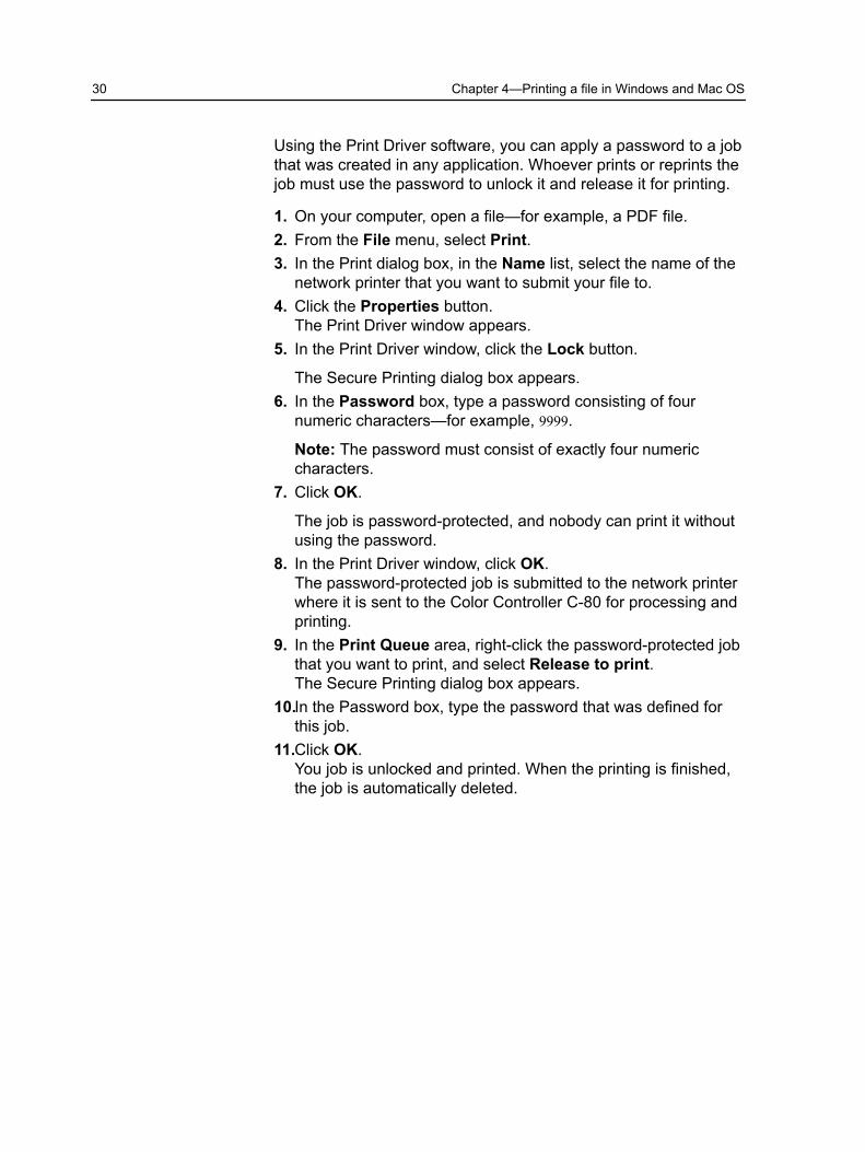
Using the Print Driver software, you can apply a password to a jobthat was created in any application. Whoever prints or reprints thejob must use the password to unlock it and release it for printing.
1. On your computer, open a file—for example, a PDF file.2. From the File menu, select Print.3. In the Print dialog box, in the Name list, select the name of the
network printer that you want to submit your file to.4. Click the Properties button.
The Print Driver window appears.5. In the Print Driver window, click the Lock button.
The Secure Printing dialog box appears.6. In the Password box, type a password consisting of four
numeric characters—for example, 9999.
Note: The password must consist of exactly four numericcharacters.
7. Click OK.
The job is password-protected, and nobody can print it withoutusing the password.
8. In the Print Driver window, click OK.The password-protected job is submitted to the network printerwhere it is sent to the Color Controller C-80 for processing andprinting.
9. In the Print Queue area, right-click the password-protected jobthat you want to print, and select Release to print.The Secure Printing dialog box appears.
10.In the Password box, type the password that was defined forthis job.
11.Click OK.You job is unlocked and printed. When the printing is finished,the job is automatically deleted.
30 Chapter 4—Printing a file in Windows and Mac OS

Using a hot folder to printUse hot folders to automate your workflow and to save time bysimultaneously submitting multiple files for printing.
You can use hot folders to process and print files from anycomputer. This tasks describes how to submit files to a hot folderfrom a Windows computer, and can also be followed for a Mac.
1. On your Windows desktop, double-click the My NetworkPlaces icon.In Mac OS, from the Finder menu, select select Go > Connectto Server.
2. Locate the Color Controller C-80, and double-click it.A list of all the shared folders, hot folders, and printers appears.
3. Double-click the desired hot folder—for example, HF_Print.
Tip: You can drag the hot folder icon to your desktop to createa shortcut to the hot folder for future use.
4. Drag the desired files to the hot folder.
All the files are processed and printed automatically, according tothe hot folder workflow.
Using a hot folder to print 31

32 Chapter 4—Printing a file in Windows and Mac OS
5 Printing from the colorserver
Importing and printing a jobYou can import a job:
● When a page-description language (PDL) file—for example,PDF or PostScript—is created on a computer that is notconnected to the Color Controller C-80
● When a PDL file is located on a folder on the network, or onexternal media, such as a CD-ROM
● When the desired file resides locally on the Color Controller C-80
1. From the File menu, select Import.2. To access the desired files, click the up one level button, or
double-click on the file folders to go down the file tree.3. In the upper list in the Import window, select the desired file(s)
and click the add button.
Note: Use SHIFT or CTRL to select several files or CTRL+A toselect all the files. If desired, add the same file more than once.
The file(s) appears in the lower list.4. Select a printer from the Virtual printer list.
Note: To remove a file, select the desired file in the lower list inthe Import Job window and click the remove button.
5. Click Import.All files currently listed on the lower list are sent to the ColorController C-80 to be processed and printed as defined in theselected virtual printer.
6. If your job is moved to the Storage area, submit the job forprinting.
Previewing and editing a PDF fileIn the Storage area, right-click the PDF file that you want topreview or edit, and select Job Preview & Editor.The file opens in Adobe Acrobat.

Editing a job overviewYou can preview and edit any PDL and RTP job that is in StorageArea. PDL files are opened in Adobe Acrobat software, and RTPfiles are opened in theJob Preview & Editor tool.
In Adobe Acrobat, you can view and edit the PDL job as you wouldnormally. In addition, this version of Adobe Acrobat includes thePitstop plugin that includes more editing tools. For moreinformation, refer to the documentation included in the software.
Note: The Enfous PitStop plugin for Adobe Acrobat is onlyavailable with the Professional Power Pack.
In the Job Preview & Editor window you can view thumbnails ofthe job while you navigate to the various pages of a job. For animposed job, you can view the imposed sheets, including thelayout of the pages on each sheet. You can also view the pages'orientation, crop marks, and fold marks.
Jobs that you edit in the Job Preview & Editor window cannot be re-RIPed. After a job is saved in the Job Preview & Editor window, itis a new RTP file without an associated PDL file. You cannot applyparameters that require re-RIPing to such jobs.
34 Chapter 5—Printing from the color server

Moving a page in a jobMove a page in an RTP job to a new location within the job.
When you move a page, the page numbers are updated accordingly.
1. In the Job Preview & Editor window, click the Thumbnails tab.2. In the Thumbnail pane, click the page that you want to move.3. Drag the page to the target location.
Note: The red marker indicates where the page will be inserted.
4. Click Save As to save the changes in the job.
Moving a page in a job 35

Deleting a page from a job1. In the Job Preview & Editor window, click the page that you
want to delete, and click Remove.The page is deleted and the page numbers are updatedaccordingly.
2. Click Save As to save the changes.
Merging one or more pages into a jobMerge one page, multiple pages, or all pages from one job intoanother.
Requirements:
The RTP job that includes the page you want to copy must havethe same page size and orientation as the job that you are editing.
1. In the Job Preview & Editor window, click the Thumbnails tab.2. In the left pane of the Thumbnails tab, determine a location for
the merged page. Click the page preceding this location.
A yellow outline appears around the selected page.3. Click Merge Jobs.
Note: Only those RTP jobs that have the same page size andorientation as the job that you are editing appear in the list.
4. Select the job with the page that you want to merge and clickOK.The job opens in a separate window.
5. Do one of the following:
● To merge one page, select the page that you want to mergeand click Merge.
Note: You can also drag the page from the job window to thedesired location in the left pane of the Thumbnails tab.
If you want to merge more than one page, repeat this stepuntil all desired pages are merged. You can also selectdifferent locations for the merged pages in the Job Preview& Editor window.
● To merge all pages into the job, click Merge All.
The merged pages are inserted into the desired location, andthe page numbers are updated accordingly.
36 Chapter 5—Printing from the color server

6. Click Close to close the job window.7. Click Save As to save the changes.
Replacing pagesIn certain cases you may have a large job and you need to replaceone of the pages. In this case you can create an RTP file of thepage which you need to replace and then using the Job Preview &Editor you can replace this page.
Requirements:
The RTP job that includes the page you want to replace must havethe same page size and orientation as the job you are editing.
1. Import and process the new page in order to create a new RTPfile.
2. Open the original RTP job in the Job Preview & Editor.3. Merge the new RTP file using the steps described in Merging
one or more pages into a job.4. Delete the incorrect page using the steps described in Deleting
a page from a job.
Proofing the jobSelect the most appropriate predefined color set to print your jobwith the best color quality. The Color Set option includes fourpredefined color sets. Each color set provides you with the bestcolor and quality settings for a specific data type or a printedproduct characteristic.
The color set options are as follows:
● Photos of people:
Provides the best color and quality settings for jobs such as afamily photo album
● Outdoor photos:
Provides the best color and quality settings for jobs that includemainly photos of landscapes
● Corporate documents:
Provides the best color and quality settings jobs that are mostlyoffice documents, such as presentation files, Web pages, andfiles with charts and logos
● Commercial materials:
Replacing pages 37

Provides the best color and quality settings for jobs that includeboth graphics and photos, such as advertising materials
To select the most appropriate color set for your job using therecommended workflow, you can print a copy of your job with eachcolor set, review the printed sample jobs, and select the best print.Then, in the Job Parameters window, you need to assign the colorset that provided the best results. If you know the color set youwant to use, you can assign a color set to your job without firstprinting and reviewing samples jobs.
Note: When you select a color set, some of the color and qualityparameters are disabled.
In this activity, you will first learn how to print sample files with allcolor set options and then how to select the most appropriate colorset in the Job Parameters window.
Assigning a color set to your jobAfter printing and reviewing the five sample files, you now need toassign the most appropriate color set to your original job.
1. In the Storage area, double-click your job.2. Under Print, select Color Set.3. In the Set list, select one of the sets that achieved the best
printed color results, for example,Outdoors photos.
38 Chapter 5—Printing from the color server
The job is assigned the color and quality parameters that arepredefined for the Outdoor photos set. The color and qualityparameters that are configured for this job, are disabled.
4. To print your job, click Submit.Collect the printouts and review the color quality.
Secure printing overviewThe Color Controller C-80 enables you to protect sensitive dataand control its printing.
Following are some of the options available:
● The Disk Wipe utility enables you to work in a more secureenvironment, by permanently removing data left by files thatyou have deleted.
See also:The Preferences window on page 135
Secure printing overview 39

40 Chapter 5—Printing from the color server
6 Managing jobs
Resubmitting a jobIn the Storage area, right-click the job that you want to submitagain, and select Submit.
Note: You can change the number of copies to be resubmittedby clicking in the Copies column and typing the requirednumber of copies.
RTP jobs are submitted to the Print queue; all other jobs aresubmitted to the Process queue.
Job Reports
Accounting Viewer overviewThe Accounting Viewer provides information about all of the jobsthat were printed successfully through the Color Controller C-80.The report is in the form of a tab-delimited file and containsdetailed information about the printed job, for example, job size,processing time, and number pages. You can filter, sort, and printthe report. You can also export the report to a spreadsheetapplication—for example, Microsoft Excel—where you canmanipulate the data. By default, all of the jobs that were handledduring the past 90 days are listed.
You can access the Accounting Viewer from the Info menu.

The accounting report also includes pages that where printed asblack-and-white or color pages. The accounting report is based onthe job's original input and the parameters that are set in the JobParameters window. To ensure the correct billing for black andwhite or grayscale jobs, perform the following actions:
● Print a job in black and white● Print a job that contains gray RGB elements as black and white
or black only
Note: Grayscale TIFF and EPS images created in CMYKapplications (such as Adobe Photoshop software) are countedcorrectly as B&W instead of Color in both the Color ControllerC-80 and the Pro C900 billing meters.
Job Report overviewThe Job Report window contains all of the information from theJob Parameters window for a specific job. The Job Report windowpresents the job parameters on a single sheet and may be printedor exported as a text file.
To access the Job Report window, in the Storage area, right-clickthe desired job, and select Job report.
42 Chapter 6—Managing jobs

PDF2Go jobsPDF2Go is a port through which you can export RTP and PDLfiles, and convert them to a PDF file during export. The ColorController C-80 is capable of exporting jobs that are standard PDFfiles, both before and after processing. For an exported RTP job,the PDF file includes the rasterized data of the job.
The operation converts the RTP information to raster files that canbe encapsulated in a PDF format. This process ensures that thefile can be processed and printed on any PDF printer.
Exporting an RTP or PDL file as a PDF fileYou can export any RTP or PDL file located in the storage folder toPDF format.
1. Select the job in the Color Controller C-80 Storage area.
PDF2Go jobs 43
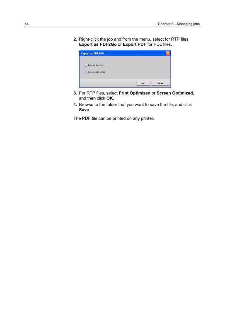
2. Right-click the job and from the menu, select for RTP filesExport as PDF2Go or Export PDF for PDL files.
3. For RTP files, select Print Optimized or Screen Optimized,and then click OK.
4. Browse to the folder that you want to save the file, and clickSave.
The PDF file can be printed on any printer.
44 Chapter 6—Managing jobs
7 Working with colorserver tools on yourcomputer
Creo Remote Site Manager
Remote Site Manager overviewThe Remote Site Manager enables a site manager to monitor thestatus of the Color Controller C-80 and other Creo color serversconnected to printers on a network. It also enables you to operatethese servers from a remote computer.
The Remote Site Manager software includes the following tools:
● The Remote Workspace tool: Allows the users to open an actualworkspace for a selected server on their client workstation andimport jobs, print jobs, preview jobs, and perform certainworkflows. Several users can connect to the same serversimultaneously from different remote workstations.
● The EZ Connect tool: Allows the users to view updated printerstatus information.
Note: You can run the Remote Site Manager on your desktop whileyou use other applications on your computer. The Remote SiteManager does not disrupt server activity.
Activating remote toolsSet up a network connection between the client workstation andthe Color Controller C-80.
The Remote Tools Setup parameter enables you to connect from aclient workstation to the Color Controller C-80 over the networkusing the Remote Site Manager.
1. From the File menu, select Preferences.
The Preferences window appears.

2. Select Remote Tools Setup.
3. In the WebViewer setup area, select Enable Webviewer.4. In the Remote workspace setup, select Enable Remote
Connection.
Tip: In this area, you can view Connection Status and howmany clients are connected.
5. Enter the amount of hours that you want the Color ControllerC-80 to logoff automatically using the arrows in the LogoffAutomatically after option.
6. Click Remote Connections Viewer to see the list of connections.7. Click Save.
Installing the Remote Site Manager in WindowsRequirements:
The remote connection option on the Color Controller C-80 mustbe activated.
1. On your desktop, click Start > Run.2. In the Run dialog box, type the exact name of the server where
the EZ Connect utility is located, as follows: \\<server_name>.3. Click OK.4. In the D:\Utilites\PC Utilities folder on the Color Controller
C-80, locate the Remote_Site_Manager.exe file.
46 Chapter 7—Working with color server tools on your computer

5. On your computer, double-click the Remote_Site_Manag-er.exe file.The Remote Site Manager is installed on your computer. TheRemote Site Manager icon appears on your taskbar afterthe application is started.
6. Click OK.
After the Remote Site Manager is installed on your clientworkstation, the Remote Site Manager appears under Start > Pro-grams > Creo Color Server > Remote Site Manager.
You can now add servers, monitor their status, and obtaininformation about the printer.
Adding Creo color servers to the Remote Site ManagerThe Remote Site Manager software enables you to set up serversvia the Remote Site Manager Setup window. You can add up tofifteen Creo color servers.
1. On the taskbar, right-click the Remote Site Manager icon.2. From the menu that appears, select Setup.
A message appears, notifying you that you need to add aserver before using the EZ Connect tool.
3. Click Ok.The Remote Site Manager Setup window appears.
4. To add a server, in the Remote Site Manager Setup window,click Add.
5. In the Hostname/IP box, type the exact name of the server thatyou want to add—for example, Server1.
6. In the Display Name box, type a name of your choice for theserver.
7. Click Add.
Your new server appears in the Remote Site Manager Setupwindow.
8. Click Save.Your new server's name appears in the Remote Site Managerright-click menu.
9. To add another server, repeat steps 4-6.
Adding Creo color servers to the Remote Site Manager 47

10.In the Hostname/IP box, type the exact name of the server youwant to add—for example, Server2
11.In the Display Name box, type a name of your choice for theserver.
12.Click Add.
Your new server appears in the Remote Site Manager Setupwindow.
You have added two servers to the Remote Site Manager.
Viewing the printer statusRequirements:
Before you can use the EZ Connect tool, you must add a server.
After you have added a server, you can the print status of theserver's Queue manager in the EZ Connect tool.
1. On the taskbar, right-click the Remote Site Manager icon.2. In the menu that appears, select EZ Connect.
The EZ Connect window appears.3. Check the status of the printer that is connected to the selected
server.
Remote Workspace overviewConnect to theColor Controller C-80 workspace, and print a job.
You can connect remotely to the Color Controller C-80 workspaceonly in servers that support the remote workspace option.
The Remote Workspace tool opens an actual workspace for theselected server and enables you to import jobs, print jobs, andperform the following workflows:
● View and manage jobs● View printer information● Set job parameters
Note: You can view multiple workspaces of available servers onthe network from one Remote Workspace. This applies only toservers of the same version and product.
Connecting to the workspace from your computerRequirements:
Make sure that you have activated the remote connection optionon the Color Controller C-80.
48 Chapter 7—Working with color server tools on your computer
1. On the taskbar, right-click the Remote Site Manager icon.2. In the menu that appears, select one of the servers.
The Remote Workspace window of that server appears.3. In the Storage area, double-click any job.
The Job Parameters window appears.4. Click Submit.
The selected job is printed.
Using the Web Center
Overview of the Web CenterThe Web Center is a web page that provides online informationand can be accessed from a Windows or Mac computer. You canconnect to the Web Center with the Internet Explorer 5.0 (or later)and Safari browsers.
The Web center enables you to:
● Download remote client tools and printer drivers● View related documentation● Find links to related vendors or products● Access the Easy VDP File Creator for creating variable data
printing files.
See also:Easy VDP File Creator tool on page 54Selecting an Easy VDP File Creator template on page 56Adding records manually to your variable data job on page 58Creating and printing the variable data job on page 60
Connecting to the Web CenterNote: To connect to the Web Center from a client workstation, youmust first enable the remote connection in the preferences of theColor Controller C-80.
1. On your desktop, double-click Internet Explorer.2. When the browser starts, in the address field type: http://
<server name>—for example, if the Color Controller C-80station name is colorserver_1, type http://colorserver_1>.The Color Controller C-80 Web Center appears.
Using the Web Center 49

See also:Easy VDP File Creator tool on page 54Selecting an Easy VDP File Creator template on page 56Adding records manually to your variable data job on page 58Creating and printing the variable data job on page 60
Office Hot Folder toolThe Office Hot Folder tool enables you to automate the printing ofMicrosoft Office files when you work remotely. You can dragMicrosoft Office files to a hot folder and then submit the files forprinting on the Creo color server.
Installing the Office Hot Folder tool1. On the Color Controller C-80, locate the D:\Utilities\PC Utilit-
ies folder.2. Double-click the Office_HF.exe file.
The Office Hot Folder tool is installed on your computer, theOffice HF icon appears on your taskbar, and the Office HotFolder tool appears. All network printers that are currently onyour computer appear in the window.
50 Chapter 7—Working with color server tools on your computer

3. Right-click this icon to perform the following actions:
● Open: Open the Office Hot Folders tool and create andmanage hot folders
● Start: Activate file processing in the tool● Stop: Deactivate file processing in the tool● Refresh: Restart the tool● Exit: Shut down the tool
Creating a hot folderRequirements:
The Office Hot Folder tool must be open.
1. In the Office Hot Folder tool, in the Printers pane, select thevirtual printer for which you want to create a hot folder.
2. Click Create HF.
You can now print Microsoft Office files through this hot folder.
Using the Office Hot Folder tool to printRequirements:
One of the following Microsoft file formats must already besubmitted to one of the hot folders setup in the Office Hot Foldertool:
● .ppt● .doc● .xls● .pub
1. In the Creo Office hot folders window, select the hot folder thatyou want to use to submit your file.
2. Drag the file to the hot folder.
Creating a hot folder 51
Your file is automatically processed and printed according to thehot folder workflow.
Creo Color Server Job Ticket software
Creo Color Server Job Ticket software overviewThe Creo Color Server Job Ticket software enables you to createa Job Definition Format (JDF) file. This JDF file contains a set ofprinting parameters (job ticket) and may also include the path to afile to be printed using those parameters.
Note: If you assign a file to a job ticket, make sure that the filelocation is accessible to the Creo color server.
Because you work on a remote computer, you don't need to beconnected to a Creo color server to create a job ticket. You canassign a job ticket to any type of file.
With the Creo Color Server Job Ticket software you can:
● Create a job ticket● Open a job ticket● Load job parameters from a selected server● Send a job to print using a job ticket that you created
Language settingsThe Creo Color Server Job Ticket software displays the languageof your computer's Windows operating system. To ensure that thelanguage that the Creo Color Server Job Ticket software displaysand the language of the Job Parameters window that you workwith are the same, set the language of your computer's operatingsystem to the same language as the Creo color server that youare creating the job ticket for.
Installing the Creo Color Server Job Ticket software1. From your computer, navigate to the D:/Utilities/PC Utilities
folder on the Creo color server.2. Double-click the CreoColorServerJobTicket.exe file.
The Creo Color Server Job Ticket software opens. A shortcut tothe Creo Color Server Job Ticket software appears under StartPrograms > Creo Color Server > Creo Color Server JT .
52 Chapter 7—Working with color server tools on your computer
Creating and managing job tickets
Creating a job ticket in WindowsRequirements:
An understanding of the Creo color server Job Parameters window
1. From the Start menu, select Programs > Creo Color Server> Creo Color Server JT > Creo Color Server Job TicketV1_0.
The Creo Color Server JT window opens displaying the JobParameters window of the server that is currently selected.
2. Set the required job parameter settings.
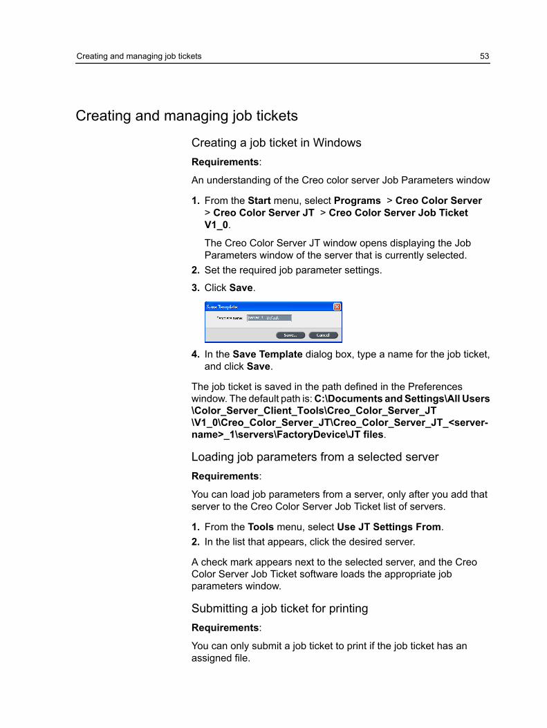
3. Click Save.
4. In the Save Template dialog box, type a name for the job ticket,and click Save.
The job ticket is saved in the path defined in the Preferenceswindow. The default path is: C:\Documents and Settings\All Users\Color_Server_Client_Tools\Creo_Color_Server_JT\V1_0\Creo_Color_Server_JT\Creo_Color_Server_JT_<server-name>_1\servers\FactoryDevice\JT files.
Loading job parameters from a selected serverRequirements:
You can load job parameters from a server, only after you add thatserver to the Creo Color Server Job Ticket list of servers.
1. From the Tools menu, select Use JT Settings From.2. In the list that appears, click the desired server.
A check mark appears next to the selected server, and the CreoColor Server Job Ticket software loads the appropriate jobparameters window.
Submitting a job ticket for printingRequirements:
You can only submit a job ticket to print if the job ticket has anassigned file.
Creating and managing job tickets 53
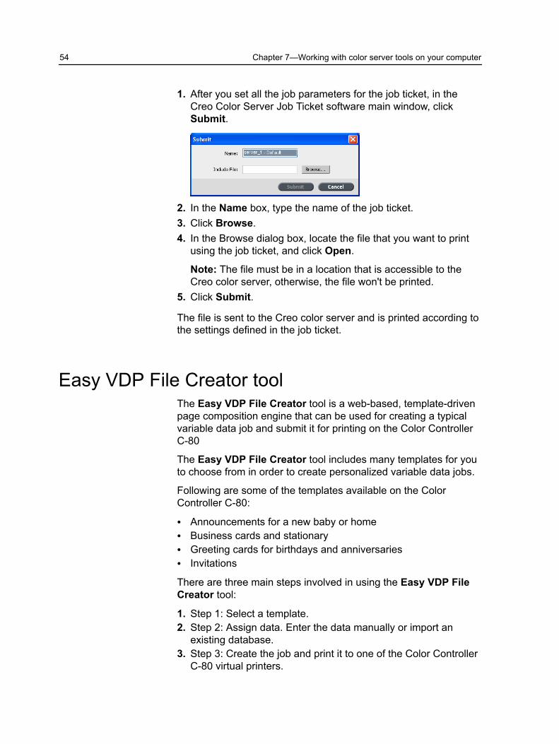
1. After you set all the job parameters for the job ticket, in theCreo Color Server Job Ticket software main window, clickSubmit.
2. In the Name box, type the name of the job ticket.3. Click Browse.4. In the Browse dialog box, locate the file that you want to print
using the job ticket, and click Open.
Note: The file must be in a location that is accessible to theCreo color server, otherwise, the file won't be printed.
5. Click Submit.
The file is sent to the Creo color server and is printed according tothe settings defined in the job ticket.
Easy VDP File Creator toolThe Easy VDP File Creator tool is a web-based, template-drivenpage composition engine that can be used for creating a typicalvariable data job and submit it for printing on the Color ControllerC-80
The Easy VDP File Creator tool includes many templates for youto choose from in order to create personalized variable data jobs.
Following are some of the templates available on the ColorController C-80:
● Announcements for a new baby or home● Business cards and stationary● Greeting cards for birthdays and anniversaries● Invitations
There are three main steps involved in using the Easy VDP FileCreator tool:
1. Step 1: Select a template.2. Step 2: Assign data. Enter the data manually or import an
existing database.3. Step 3: Create the job and print it to one of the Color Controller
C-80 virtual printers.
54 Chapter 7—Working with color server tools on your computer
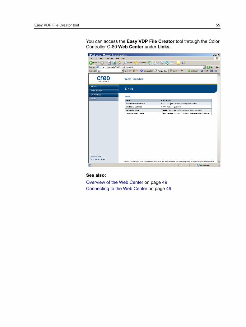
You can access the Easy VDP File Creator tool through the ColorController C-80 Web Center under Links.
See also:Overview of the Web Center on page 49Connecting to the Web Center on page 49
Easy VDP File Creator tool 55

Selecting an Easy VDP File Creator templateThe first step in creating a variable data job is to select the type ofjob and template that will be printed.
1. Open the Easy VDP File Creator tool from the Color ControllerC-80 Web Center.
The Easy VDP File Creator tool opens and lists the templatesavailable.
2. In the Templates area, select the category and subject of thetype of variable data job that you want to create, for example,Announcements > New baby.The templates matching this selection appear in the Designand properties area.
56 Chapter 7—Working with color server tools on your computer
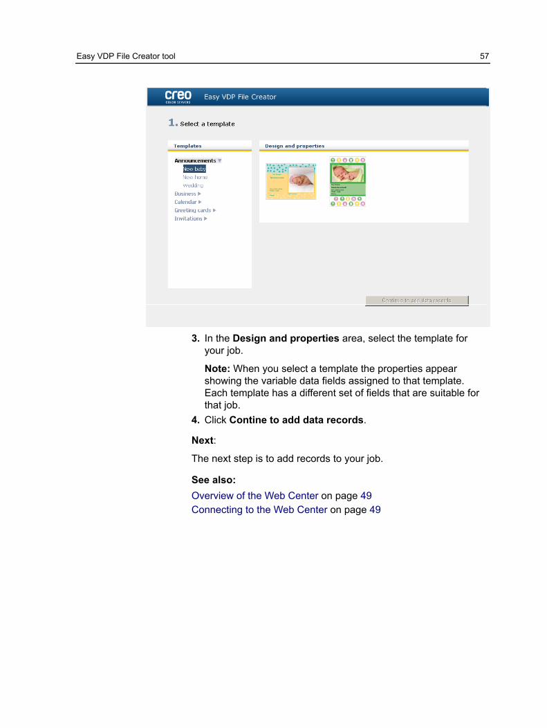
3. In the Design and properties area, select the template foryour job.
Note: When you select a template the properties appearshowing the variable data fields assigned to that template.Each template has a different set of fields that are suitable forthat job.
4. Click Contine to add data records.
Next:
The next step is to add records to your job.
See also:Overview of the Web Center on page 49Connecting to the Web Center on page 49
Easy VDP File Creator tool 57
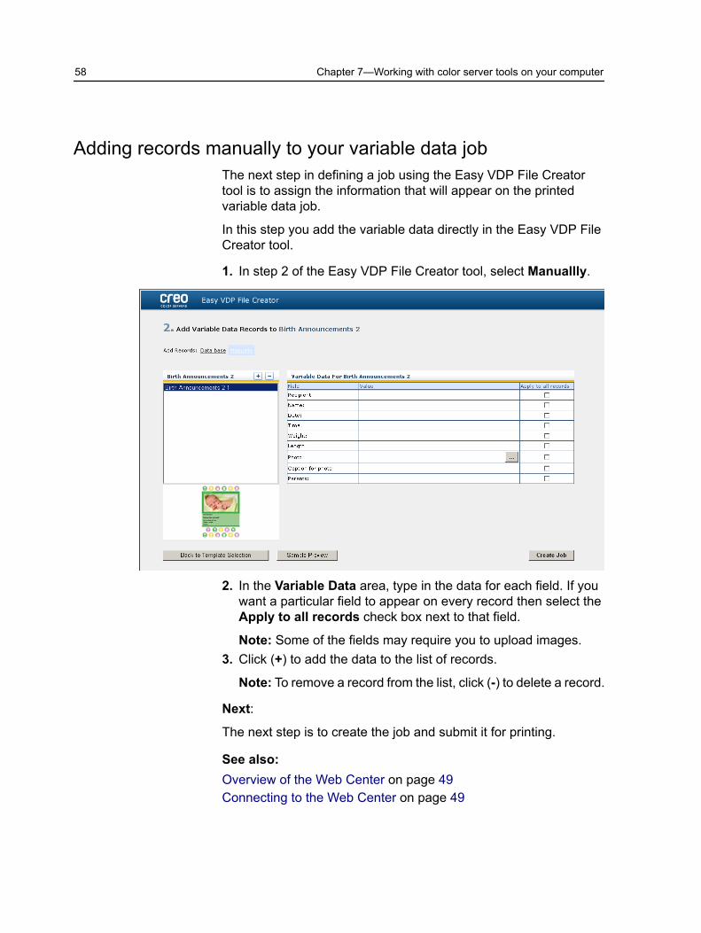
Adding records manually to your variable data jobThe next step in defining a job using the Easy VDP File Creatortool is to assign the information that will appear on the printedvariable data job.
In this step you add the variable data directly in the Easy VDP FileCreator tool.
1. In step 2 of the Easy VDP File Creator tool, select Manuallly.
2. In the Variable Data area, type in the data for each field. If youwant a particular field to appear on every record then select theApply to all records check box next to that field.
Note: Some of the fields may require you to upload images.3. Click (+) to add the data to the list of records.
Note: To remove a record from the list, click (-) to delete a record.
Next:
The next step is to create the job and submit it for printing.
See also:Overview of the Web Center on page 49Connecting to the Web Center on page 49
58 Chapter 7—Working with color server tools on your computer

Adding records from a database to your variable data jobThe next step in defining a job using the Easy VDP File Creatortool is to assign the information that will appear on the printedvariable data job.
In this step you can upload an Excel file containing the variabledata information that you want to appear on each record.
Note: The Excel file must include the same fields as defined in theproperties of the template that you selected.
1. In step 2 of the Easy VDP File Creator tool, select Database.
2. Click Browse to upload your Excel database file, or clickCreate Database File.
Note: When you select Create Database File, Excel openswith a worksheet containing the field names in the first rowsuitable for the template you selected.
Adding records from a database to your variable data job 59
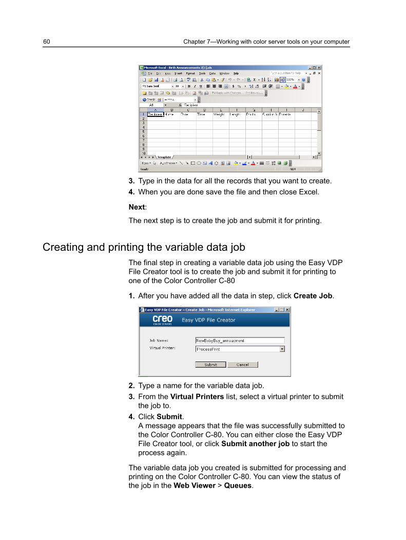
3. Type in the data for all the records that you want to create.4. When you are done save the file and then close Excel.
Next:
The next step is to create the job and submit it for printing.
Creating and printing the variable data jobThe final step in creating a variable data job using the Easy VDPFile Creator tool is to create the job and submit it for printing toone of the Color Controller C-80
1. After you have added all the data in step, click Create Job.
2. Type a name for the variable data job.3. From the Virtual Printers list, select a virtual printer to submit
the job to.4. Click Submit.
A message appears that the file was successfully submitted tothe Color Controller C-80. You can either close the Easy VDPFile Creator tool, or click Submit another job to start theprocess again.
The variable data job you created is submitted for processing andprinting on the Color Controller C-80. You can view the status ofthe job in the Web Viewer > Queues.
60 Chapter 7—Working with color server tools on your computer

See also:Overview of the Web Center on page 49Connecting to the Web Center on page 49
Easy VDP File Creator tool 61

62 Chapter 7—Working with color server tools on your computer

8 Managing color
Color tools overviewThe Color Controller C-80provides you with a number of tools andoptions that enable you to adjust and improve the color quality inyour jobs.
The following tools are available:
● Profile Manager● Spot Color Editor● Gradation Tool● Calibration table editor● Media and Color Manager
Managing color and profilesA profile is a file that describes how a particular device reproducescolor. It represents the colorimetric behavior of a given device forknown media and imaging parameters (such as substrate/paperstock, resolution, and inks). Profiles are used to reproduce colorfrom one device’s color space to another device's color space in aconsistent manner. They provide the necessary information toconvert color data between device-dependent color spaces anddevice-independent color spaces. You use profiles to color manageyour system.
Color management is a series of steps taken to ensure that colorsare accurate and repeatable when transferred from one device toanother. Color management helps us reproduce the colorconceived by a graphic artist or photographer as closely aspossible on a monitor, a proof, or a press sheet. Colormanagement enables accurate and repeatable color reproduction,within each device’s color capability, throughout the entire workflow.
Before you can print a color document, the color data in it must beconverted to the gamut of the printer. Whether performed by theColor Controller C-80 or a host-based CMS, the process ofconverting color data for a printer is the same: the CMS interpretsRGB object data according to a specified source profile andadjusts both RGB and CMYK data according to a specified output

profile, also called a destination profile by some colormanagement systems.
The source profile defines the RGB color space of the object’ssource: characteristics such as the white point, gamma, and typeof phosphors used. The output profile defines the gamut of anoutput device, such as a printer. The Color Server (or host-basedCMS) uses a deviceindependent color space to translate betweenthe source color space and the color space of the output device.
The Profile Manager on the Color Controller C-80 enables you tocreate destination profiles which define the color space of yourprinter and are based on the combinations of paper and toner thatyou are using. For different media types, you need differentdestination profiles.
Importing a destination profileIf you saved a profile in a location other than the Profile Manager,you must first import it before you can print a job using it.
Note: After you import the profile the file becomes *.icm format.
1. From the Tools menu, select Resource Center.
The Resource Center window appears.2. In the Resource list, select Profile Manager.
64 Chapter 8—Managing color
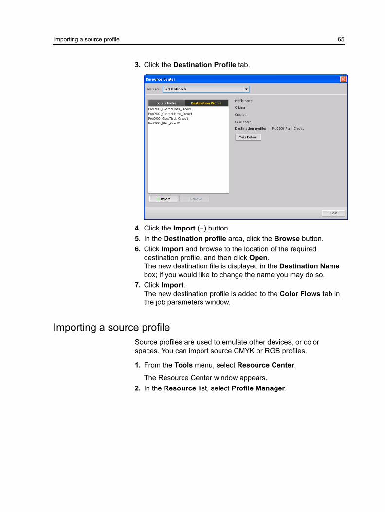
3. Click the Destination Profile tab.
4. Click the Import (+) button.5. In the Destination profile area, click the Browse button.6. Click Import and browse to the location of the required
destination profile, and then click Open.The new destination file is displayed in the Destination Namebox; if you would like to change the name you may do so.
7. Click Import.The new destination profile is added to the Color Flows tab inthe job parameters window.
Importing a source profileSource profiles are used to emulate other devices, or colorspaces. You can import source CMYK or RGB profiles.
1. From the Tools menu, select Resource Center.
The Resource Center window appears.2. In the Resource list, select Profile Manager.
Importing a source profile 65

3. Select Source Profile tab.
4. Click the Import button.5. In the Source profile area, click the Browse button.6. Locate and select the required source profile, and then click
Open.The new emulation name is displayed in the Emulation namebox; if you would like to change the name you may do so.
7. Click Import.The new source ICC profile is added to the Color Flows tab inthe job parameters window.
Mapping media using the Media and ColorManager tool
The Media and Color Manager is a tool that maps the media typeto a destination profile.
You can change the destination profile for each of the differentmedia types listed in the Media and Color Manager. The ColorController C-80 is configured with a default recommend profile.
66 Chapter 8—Managing color
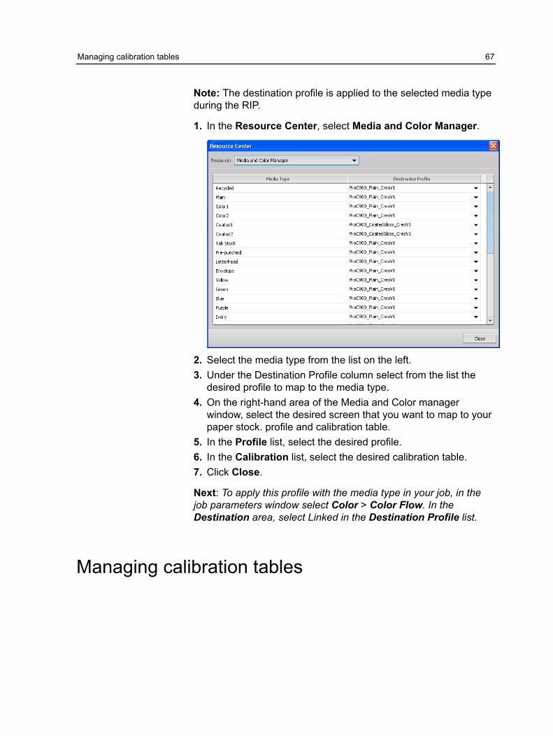
Note: The destination profile is applied to the selected media typeduring the RIP.
1. In the Resource Center, select Media and Color Manager.
2. Select the media type from the list on the left.3. Under the Destination Profile column select from the list the
desired profile to map to the media type.4. On the right-hand area of the Media and Color manager
window, select the desired screen that you want to map to yourpaper stock. profile and calibration table.
5. In the Profile list, select the desired profile.6. In the Calibration list, select the desired calibration table.7. Click Close.
Next: To apply this profile with the media type in your job, in thejob parameters window select Color > Color Flow. In theDestination area, select Linked in the Destination Profile list.
Managing calibration tables
Managing calibration tables 67

Calibrations windowYou can edit any of the calibration look-up tables (LUTs) that arestored on the Color Controller C-80. You can find the calibrationtable information in Tools > Resource Center > Calibrations.
Calibration table listThe following calibration tables are listed:
● Calibration tables created in the Calibration Wizard.● None: This is a default option and cannot be edited. Jobs that
have this option selected are processed and printed withoutusing a calibration table.
● Normal (default table): This is a default table and cannot beedited. If a calibration table has not been created for the mediatype, Normal weight, and screening method that you are using,the Normal calibration table is used when you process and printyour job.
Info Data
Output Density Measured: The values that are measure fromthe printed target.Target: The expected values of the outputdensity.Minimum Accepted: The minimum measuredvalue of the output density that is accepted forcorrection.
68 Chapter 8—Managing color
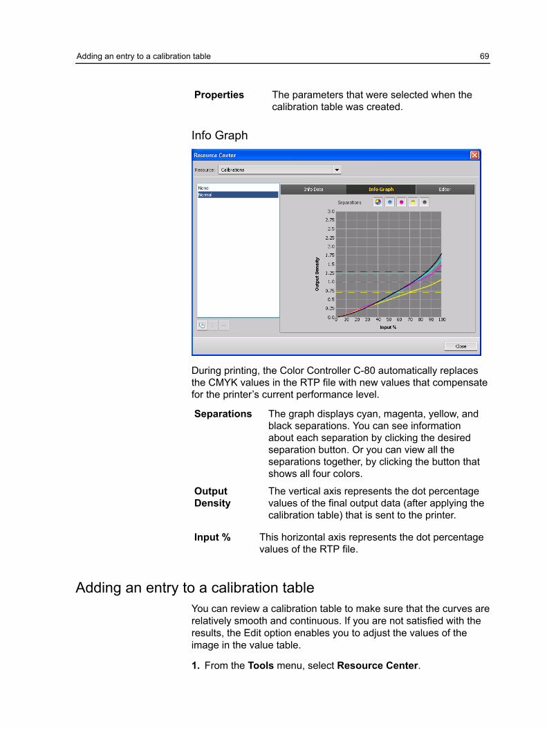
Properties The parameters that were selected when thecalibration table was created.
Info Graph
During printing, the Color Controller C-80 automatically replacesthe CMYK values in the RTP file with new values that compensatefor the printer’s current performance level.
Separations The graph displays cyan, magenta, yellow, andblack separations. You can see informationabout each separation by clicking the desiredseparation button. Or you can view all theseparations together, by clicking the button thatshows all four colors.
OutputDensity
The vertical axis represents the dot percentagevalues of the final output data (after applying thecalibration table) that is sent to the printer.
Input % This horizontal axis represents the dot percentagevalues of the RTP file.
Adding an entry to a calibration tableYou can review a calibration table to make sure that the curves arerelatively smooth and continuous. If you are not satisfied with theresults, the Edit option enables you to adjust the values of theimage in the value table.
1. From the Tools menu, select Resource Center.
Adding an entry to a calibration table 69

2. In the Resource list, select Calibrations.3. Select the calibration table that you want to add an entry, and
click the Editor tab.
4. From the Separation list, select the desired separation to thatyou want to add an entry.
The file and printer values for the separation that you selectedappear in the File Value and Printer Value lists.
5. Select a row in the value table, and click the Add (+) button.6. In the Add Entry window, from the File Value and Printer
Value lists, select the desired values.
7. Click OK.The value table is updated, and the calibration graph is adjusted.
8. To save your changes, click the Save button.
Managing spot colorsYou can define a specific color as an RGB, CMYK, or Gray spotcolor and enter a fixed CMYK target.
70 Chapter 8—Managing color

Individual job pages can contain RGB, CMYK, and spot colorelements. A spot color is a specially mixed ink that enables you toreproduce colors that are difficult to reproduce with CMYK inks.
The Color Controller C-80 Spot Color Editor enables you to editthe values of every spot color in the Spot color dictionary. You canedit these values without affecting the graphics, images, or lineartpage elements.
When a spot color is converted to CMYK for digital printing, theprintout doesn’t always simulate the desired spot color. The spotcolor variations feature enables you to easily edit a spot color byselecting a more appropriate shade. The spot color variationsfeature provides 37 variations, with slightly different CMYK values.
Note: The Spot Variations tool is only available with theProfessional Power Pack.
The spot color variations feature enables you to set:
● The variation of cyan, magenta, and yellow dot percent, byselecting variations of 1-7%. The default selection is 2%.
● The change in the hue, by selecting variations in the cyan,magenta, yellow, red, green, and blue axis.
● The brightness, by increasing or reducing the K value by up to20%.
You can assess your changes immediately in the Before andAfter boxes, or you can print the entire set of variations, anddecide which best fits your requirements by examining theprintout. The edited spot color is saved in a custom dictionary.When the Color Controller C-80 identifies a spot color in a job, itfirst looks for the name of the spot color in the custom dictionaryand uses the associated CMYK values. If the spot color is notfound, it looks in the PANTONE® color and HKS® colordictionaries. If the spot color is not found in either dictionary, theColor Controller C-80 uses the CMYK values embedded in theoriginal file.
Managing spot colors 71

Adding a spot color1. From the Tools menu, select Spot Color Editor.2. In the Spot Color Editor dialog box, click the add (+) button.
3. Type the new color name as it exists in the orginal file.
Note: The spot color names are case sensitive and shouldmatch the name as it appears in the DTP software.
4. Adjust the CMYK values as required.5. Click Save.6. Click Close.
72 Chapter 8—Managing color

The new color is added to the custom color dictionary.
If you created a new spot color for an RTP job, make sure you re-RIP the job before printing.
Editing a spot color
1. From the Tools menu, select Spot Color Editor.2. Do one of the following actions:
● In the Color list, search for the desired color.● In the Spot color dictionary list, select the color dictionary
that contains the color you want to edit.
Note: Use the PANTONE C dictionary if you are working inan application such as Adobe InDesign software.
3. Highlight the required color.The color's CMYK values and color preview appear in the righthand side of the Spot Color Editor window.
4. Change the CMYK values as required.5. Click Apply.
The new color is added to the custom color dictionary.
Deleting a spot colorYou can only delete spot colors from the custom color dictionary.
1. In the Spot dictionary list, select Custom Dictionary.2. From the list of custom colors, highlight the color you wish to
delete.3. Click remove (x) icon.4. Click Yes to delete the color.
Printing a spot color chartSetup and print a spot color chart in order to test the output.
In order to make sure that the spot colors will print correctly youcan send a test print of selected spot colors. According to theresults of the print out you can then make the necessaryadjustments to the spot colors using the Spot Color Editor.
Note: You can only print a spot color chart for CMYK values.
1. From the Tools menu, select Spot Color Editor.
Editing a spot color 73

2. Click Test Print.
3. Select a Spot color dictionary from the list and then select thepantone patches that you want to print.
4. Click Print, and then select the following:
● In the Screening list, select the desired screening method.5. Click Print, to print the spot color test chart.
Spot color variations overviewThe Spot color variations tool is only available with theProfessional Power Pack.
A spot color is a specially mixed ink that enables you to reproducecolors that are difficult to reproduce with CMYK inks. When a spotcolor is converted to CMYK for digital printing, the printout doesn’talways simulate the desired spot color. The spot color variationsfeature enables you to easily edit a spot color by selecting a moreappropriate shade. The spot color variations feature provides 37variations, with slightly different CMYK values.
74 Chapter 8—Managing color
The spot color variations feature enables you to set:
● The variation of cyan, magenta, and yellow dot percent, byselecting variations of 1-7%. The default selection is 2%.
● The change in the hue, by selecting variations in the cyan,magenta, yellow, red, green, and blue axis
● The brightness, by increasing or reducing the K value by up to20%.
You can assess your changes immediately in the Before and Afterboxes, or you can print the entire set of variations, and decidewhich best fits your requirements by examining the printout.
The edited spot color is saved in a custom dictionary. When theColor Controller C-80 identifies a spot color in a job, it first looksfor the name of the spot color in the custom dictionary and usesthe associated CMYK values. If the spot color is not found, it looksin the PANTONE color and HKS color dictionaries. If the spot coloris not found in either dictionary, the Color Controller C-80 uses theCMYK values embedded in the original file.
Selecting a spot color variation
1. From the Tools menu, select Spot Color Editor.2. In the Color list, type the name of the spot color.
The spot color is automatically selected from the spot Color list.
3. Click the Variations button.
The Variations dialog box appears. The spot color is in thecenter of the color patches and is designated as "0".
4. Click and slide the Variation steps slider to see the differentvariation steps between 1 to 7 color units of the original value.Each unit refers to a dot percentage of the original value.
5. To see the CMYK values of a color patch, roll your mouse overthe color patch.
The CMYK values appear in the bottom left corner of the dialogbox.
6. To select a variation of the spot color, click on the desired colorpatch.
You can see the difference between the selected color patchand the original spot color in the Before and After box.
Selecting a spot color variation 75

7. To select a different brightness setting for the selected colorpatch, click a color patch under Brightness.
The K value of the selected color patch is increased ordecreased according to your selection.
8. Click Select.9. Click Apply.
The spot color with the new values is added to the CustomDictionary.
10.Click Close.
Printing a spot color variationRequirements: Make sure that the printer is connected andturned on and all the queues on the Color Controller C-80 areready for processing and printing.
1. From the Tools menu, select Spot Color Editor.
76 Chapter 8—Managing color
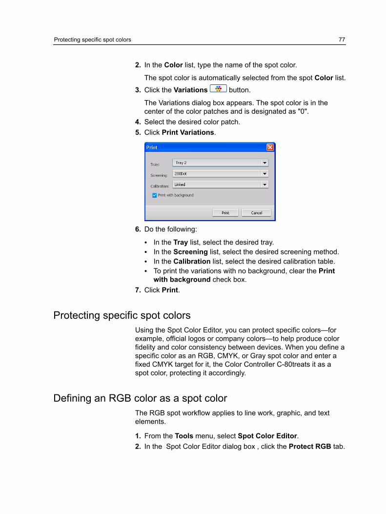
2. In the Color list, type the name of the spot color.
The spot color is automatically selected from the spot Color list.
3. Click the Variations button.
The Variations dialog box appears. The spot color is in thecenter of the color patches and is designated as "0".
4. Select the desired color patch.5. Click Print Variations.
6. Do the following:
● In the Tray list, select the desired tray.● In the Screening list, select the desired screening method.● In the Calibration list, select the desired calibration table.● To print the variations with no background, clear the Print
with background check box.7. Click Print.
Protecting specific spot colorsUsing the Spot Color Editor, you can protect specific colors—forexample, official logos or company colors—to help produce colorfidelity and color consistency between devices. When you define aspecific color as an RGB, CMYK, or Gray spot color and enter afixed CMYK target for it, the Color Controller C-80treats it as aspot color, protecting it accordingly.
Defining an RGB color as a spot colorThe RGB spot workflow applies to line work, graphic, and textelements.
1. From the Tools menu, select Spot Color Editor.2. In the Spot Color Editor dialog box , click the Protect RGB tab.
Protecting specific spot colors 77

3. Click add (+).
4. In the Color name box, type a name for your color.5. Type the RGB source values and the CMYK target values, or
select a spot color from the Entire Predefined List.6. Click Save.7. On the Protect RGB tab, select the color.
The color information appears.
8. If necessary, in the Corrected column, adjust the CMYK values.9. Click Apply.
Defining a gray color as a spot colorThe gray spot workflow applies only to line work and text elements.
1. From the Tools menu, select Spot Color Editor.
78 Chapter 8—Managing color

2. In the Spot Color Editor dialog box , click the Protect Gray tab.
3. Click add (+).
4. In the Color name box, type a name for your color.5. Enter the Gray source value and CMYK target value, or
select a spot color from the Entire Predefined List.6. Click Save.7. On the Protect Gray tab, select the color.8. If necessary, in the Corrected column, adjust the CMYK values.9. Click Apply.
Defining a CMYK color as a spot colorThe CMYK spot workflow applies only to line work and text elements.
1. From the Tools menu, select Spot Color Editor.
Defining a CMYK color as a spot color 79

2. In the Spot Color Editor dialog box , click the Protect CMYK tab.
3. Click add (+).
4. In the Color name box, type a name for your color.5. Enter the CMYK source value and CMYK target value, or
select a spot color from the Entire Predefined List.6. Click Save.7. On the Protect CMYK tab, select the color.8. If necessary, in the Corrected column, adjust the CMYK values.9. Click Apply.
Color adjustment with the Gradation ToolSometimes you need to perform tone corrections when you print ajob. TheColor Controller C-80 enables you to create a gradationtable that will correct your printed output. Changes in gradationcan include brightness, contrast, and color balance adjustmentsthroughout the tone range of an entire image or in specific toneranges.
The Gradation Tool window enables you to create and editgradation tables as well as visually check the effect of yourgradation tables on a specific processed job. The new gradationtables you create are added to the Gradations list in the Colorparameter and can be applied to print jobs.
80 Chapter 8—Managing color

To open the Gradation Tool window:
From the Tools menu, select Gradation or click on the GradationTool icon from the toolbar.
Previewing a job1. From the Tools menu, select Gradation.2. Next to the Preview File box, click Browse.3. Select the job that you want to preview, and then click Open.
The Original and Edited views display your job.
Creating a new gradation table1. From the Tools menu, select Gradation.2. In the Gradation Tool window, modify your gradation table as
required.3. Click Save .4. In the Table name box, type the name of the new gradation table.5. Click OK.
The gradation table is saved and added to the Gradation Tablelist and to the Color Adjustments tab in the job parameters window.
Previewing a job 81
Editing a gradation tableWhen you open the Gradation Tool, the default gradation table,DefaultGradTable, is selected in the Gradation Table list, and isdisplayed in the graph. This table serves as a baseline andconsists of a 45° gradation curve, with Brightness and Contrast setto 0, and Contrast Center set to 50. All of the color separations areselected.
The Gradation Table list includes four other predefined gradationtables:
● Cool: Blue tones appear clearer● Lively: Increases the color saturation● Saturated: Increases the strength (chroma or purity)● Sharp: Increases the contrast● Warm: Sets the hues in the low densities to a bright reddish color
Gradation tables that you create or edit also appear in theGradation Table list. When you select a gradation table, thepredefined settings are immediately applied to the processed jobthat you are working with. The Separations buttons enable you toselect one, all, or any combination of separations to edit for aspecific gradation table. Selecting a specific separation enablesyou to change the color balance for a specific tonal orange. Whenyou open the Gradations Tool window, all of the separations areselected.
Note: When you change gradation table definitions in theGradation tool and click Refresh, you will notice that the changeshave affected the image in its entirety. However, despite what yousee in the Edited view, changes made to the gradation tables donot affect spot colors.
1. From the Tools menu, select Gradation.2. To edit the separations, do one of the following:
● Click the All Colors button to edit all the separationssimultaneously.
● Click the individual separations you wish to edit—forexample, select the cyan separation only.
3. Click the curve in the graph to add a point, and then drag thepoint to modify the separation.The value appears in the Input or Output boxes.
4. To view gradation changes in your job, click Refresh.Changes are automatically applied to the displayed image inthe After view.
82 Chapter 8—Managing color
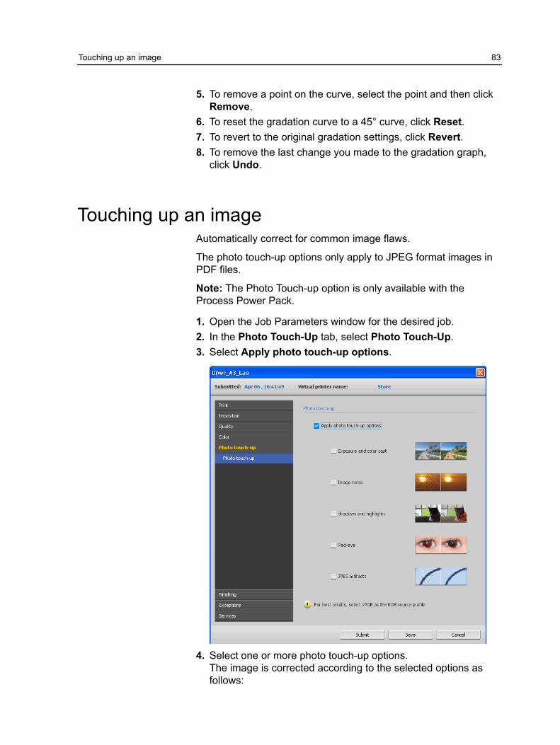
5. To remove a point on the curve, select the point and then clickRemove.
6. To reset the gradation curve to a 45° curve, click Reset.7. To revert to the original gradation settings, click Revert.8. To remove the last change you made to the gradation graph,
click Undo.
Touching up an imageAutomatically correct for common image flaws.
The photo touch-up options only apply to JPEG format images inPDF files.
Note: The Photo Touch-up option is only available with theProcess Power Pack.
1. Open the Job Parameters window for the desired job.2. In the Photo Touch-Up tab, select Photo Touch-Up.3. Select Apply photo touch-up options.
4. Select one or more photo touch-up options.The image is corrected according to the selected options asfollows:
Touching up an image 83

● Exposure and color cast:
Correct underexposure, overexposure, and minor color-castproblems in photos.
● Image noise:
Reduce noise (such as granularity caused by high ISOsettings) in a photo.
● Shadows and highlights:
Bring out details in the dark and light areas of a photo.● Red-eye:
Remove the red-eye effect in photos taken with a flash.● JPEG artifacts
Remove JPEG artifacts often found in low-quality or highlycompressed JPEG files, particularly in gradient and vignetteareas and around the edges of objects.
5. Select Submit.The job is sent to the Process Queue.
84 Chapter 8—Managing color

9 Production workflows
Print using imposition
Imposition overviewImposition is the process of positioning page images on a virtualsheet of paper so that when a printer or digital printing press printsthe sheet, the page images will be in the right order. It is part of theprocess of producing finished documents.
In addition to page images, you can add various marks to thesheets to aid the production process. These marks show where thepaper should be folded or trimmed.
Imposition does not affect the content of the individual page butrather affects only the placement of the page images on a presssheet. Imposition is a combination of content and layout. Thecontent is the pages that should be printed, and the layout is thelocation of the page on the sheet, along with the page’s printingmarks, crop marks and fold marks.
See also:Imposition tab in the Job Parameters window on page 112
Previewing an imposition layoutThe Preview window enables you to view your imposition layoutand settings.
Requirements:
An imposition method must be selected.
You can open the Preview window at any time and keep it open tocheck your imposition settings as you select them. The Previewwindow dynamically reflects any changes that you make.
1. Open the Job Parameters window for the desired job.2. Click the Imposition tab, and make sure that an imposition
method has been selected.

3. Click the Preview button.The Preview window appears.
Imposition layout Preview window
Preview window buttons
Front Click to view the front pages.
Back Click to view the back pages.
Navigationbuttons
Click the navigation arrows to move betweensheets.
Navigation boxJump to a specific sheet by typing a number inthe navigation box.
Page image
Gray arrows Indicate the direction of the pages on the sheet.
Page numbers Indicate the numbered sequence of the pages.
Imposition ConflictIf any parameters conflict, Imposition Conflict appears in red inthe Preview window and also on the Imposition tab.
86 Chapter 9—Production workflows

Imposition Conflict
Conflictindications A red border along the edge of the page
indicates where the conflict exists.
● If the red border appears along the upperand lower edges of the page, a conflictexists in the height value.
● If the red border appears along the left andright edges of the page, a conflict exists inthe width value.
Problematic values appear in red.
Printing a business card jobRequirements:
This example assumes that your job contains one-sided businesscards that are 50 mm × 90 mm (1.96 in. × 3.45 in.), imposed on A3paper.
This example demonstrates how to use the Step & Repeatimposition method to print business cards. With the Step &Repeat method, you can print multiple copies of the same imageon one large sheet.
1. Click the suspend button to suspend the Process queue.2. From the File menu, select Import.3. Import your business card file to the virtual printer.
The file is imported to the Process queue with a Waiting status.
Printing a business card job 87

4. In the suspended Process queue, double-click the businesscard file.The Job Parameters window appears.
5. Click the Imposition tab.6. In the Imposition Method list, select Step & Repeat.7. Select the Size parameter, and set the values as follows:
a. For Trim Size, select Customb. For H, type 1.96 inches or 50 mmc. For W, type 3.54 inches or 90 mm
8. For Trim orientation, make sure that the Landscape option isselected. To change the trim orientation, in the Job Parameterswindow, select Print and then select Layout. Select the desiredorientation.
9. Select the Templates parameter, and set the values as follows:a. In the Layout list, select Best Fit. The Color Controller C-80
determines how many business cards can fit on each sheet.The Color Controller C-80 calculates the best fit, a layout ofthree columns by eight rows.
b. For Print Method, make sure Simplex is selected, sinceyour business cards are one-sided.
10.Click the Preview button to preview the layout.
The Preview window appears, displaying a schematicrepresentation of your imposition layout. The layout of threecolumns by eight rows appears with no imposition conflict.
88 Chapter 9—Production workflows

11.Leave the Preview window open, and, if necessary, drag it tothe right.
12.Select the Spacing & Marks parameter.13.In the Marks list, select Crop marks.
The crop marks automatically appear in the Preview windowand the Margins size is automatically increased toaccommodate the crop marks.
14.In the Gutter box, type 0.2 inches or 5 mm.As soon as you change the value for the Gutter size, theimposition layout in the Preview window automatically changes.The Color Controller C-80 calculates that to accommodate agutter of 0.2 inches or 5 mm, a layout of three columns byseven rows will best fit on each sheet.
15.Check the Preview window. No imposition conflicts appear.16.In the Job Parameters window, click Save.17.Release the suspended Process queue.
Your business cards are processed and printed according tothe imposition settings.
Print using imposition 89

Printing a saddle stitch jobRequirements:
This example assumes the following:
● Your job is an eight-page brochure, with a custom trim size of5.27 by 3.34 inches or 134 by 85 mm.
● Tabloid or A3 paper is loaded in the printer.
This example demonstrates how to use the Saddle Stitchimposition method to print two sets of the same job on one presssheet to save paper and production time.
1. In the Storage area, double-click your job.2. In the Job Parameters window, click the Imposition tab.3. In the Method list, select Saddle stitch.4. In the Sets per sheet list, select 2 to print two sets of your
imposed job on one press sheet.5. Click Spacing & Marks.6. In the Marks list, select Crop marks.7. In the Bleed box, type 0.118 inches or 3 mm.8. Click the Preview button.
A schematic representation of the imposition layout appears.
Note: When you print your job, a space of 0.39 inches or 10mm is automatically added between the two sets on the sheet.
9. Close the Preview window.10.Click Submit.
Your job is processed and printed according to the impositionsettings for two sets per sheet. You have used most of thesheet's space and saved on paper. You can also easily cut andstaple the two brochures.
Imposition Template Builder Tool
Imposition Template Builder overviewThe Imposition Template Builder is only available with theProfessional Power Pack.
The Imposition Template Builder enables you to save impositionlayouts and reuse them for different jobs, without needing to definethe same layout repeatedly. The Imposition Template Builder alsoallows you to create and save templates with special layouts thatcannot be created on the Imposition tab alone.
90 Chapter 9—Production workflows

After you save a template, you can apply it to a specific job.
All saved templates appear on the Imposition tab. After youselect an imposition method, the related templates appear in theTemplate parameters, in the Layout list. For example, if youcreated a Step & Continue template, the template appears in theLayout list only when you select the Step & Continue impositionmethod.
Some templates appear under more than one imposition method.
Method selected onImposition tab:
Template layout type in the layout list:
Step & Repeat Step & Repeat, Cut & Stack
Step & Continue Step & Continue
Saddle Stitch Saddle Stitch, Perfect Bound
Perfect Bound Saddle Stitch, Perfect Bound
Note: Templates created in Ultimate software cannot be importedor used in the Color Controller C-80. They must be created usingthe Imposition Template Builder.
Creating an imposition templateOn the Color Controller C-80, you can use the Imposition TemplateBuilder to create templates for similar types of jobs that have thefollowing imposition settings in common:
● Imposition method● Columns and rows● Simplex/duplex● Binding
For example, if you want to create an imposition template for A4-sized brochures printed on A3 paper, you could create a template,called “A4Brochure”, and select the following settings:
● Imposition method: Saddle Stitch● Columns: 2● Rows: 1● Type: Duplex (selected by default)● Binding: Left
Creating an imposition template 91

You would define all the other imposition settings—for example,Trim Size, Bleed, Margin, Gutters, and Paper Size—on theImposition tab.
1. From the Tools menu, select Imposition Template Builder.
2. From the Method list, select an imposition method.3. Click the New (+) button.4. Type the name of the new template, and press Enter.5. In the Layout area, type the number of columns and number of
rows that you need.The imposition method that you select determines the numberof columns and rows that you can enter. For Saddle Stitch andPerfect Bound, you can place up to 64 pages on one sheet (8× 8). For Step & Repeat and Step & Continue, you can placeup to 625 pages on one sheet (25 × 25).
6. Under Type, select Simplex or Duplex.7. Under Orientation, select Portrait or Landscape.
Note: The Orientation setting in the Imposition TemplateBuilder is for display purposes only. This parameter is notsaved in the template. (You set job orientation on theImposition tab, under Size).
8. From the Binding list, select the appropriate binding method.
Note: Binding is available only when Saddle Stitch andPerfect Bound imposition methods are selected.
9. Click Save.
Imposition template viewer windowAs you create or modify a template, you can see your template inthe template viewer. As you select parameters, the templateviewer dynamically changes to reflect your selections.
92 Chapter 9—Production workflows

ButtonsNotes:● When Simplex is selected, only the Front view is available.● Sheet size is set on the Imposition tab. The sheet size that
appears in the template viewer is dynamic. It changes toaccommodate the parameters that you choose.
Front Click to view the front pages.
Back Click to view the back pages.
Both Click to view both the front and back pagessimultaneously.
Editing an imposition template
Rotating a page 180 degrees
The template viewer enables you to rotate one or more pages andchange the location of pages on the sheet.
The gray arrow on each page indicates the top of the page. Thepage number is indicated by the number that appears on each page.
1. Make sure the Apply changes to front and back check box isclear.
2. Select the desired page.
Note: To select multiple consecutive pages, click the first page,press and hold Shift, and then click the last page. Selectmultiple non-consecutive pages by pressing and holding Ctrl asyou click each page.
Editing an imposition template 93

3. Click the Rotate 180 button.
Rotating both the front and back sides of a page 180 degrees
1. Select the desired page.2. Select the Apply changes to front and back check box.3. Click the Rotate 180 button.
Changing the position of a specific page on a press sheet
You can change the location of a page on a sheet as needed.Changing the location of a page is often necessary when the Step& Continue imposition method is selected.
1. Click the target location that you want to move the page to—forexample, click page 10 if you want to place a different page inthat location.
The target location turns blue when selected.
2. Click the Page Number box, and type the number of the pagethat you want to move to the target location. For example, youwould type 5 to place page 5 in the location of page 10.
3. Press Enter.
The page moves to its new location.
94 Chapter 9—Production workflows

Note: The page number that was previously in the targetlocation is not automatically moved to another location. Toretain this page, manually move this page to a new location.
If you have a duplex job and the Apply changes to front andback check box is selected, the page number for the back sideof the page also changes. Using the example above, page 6would be on the back side of page 5.
Simulating a job with your templateYou can simulate how jobs from the Storage window will look ifyou apply an imposition template to them.
Note: The impostion template parameters are not actually appliedto the job—you are viewing only a simulation of how the job wouldlook if this template were selected on the Imposition tab.
1. In the Imposition Template Builder window, click the Simulatebutton.
2. Click Browse.3. Select a job, and then click Select.
The parameters of the job (Sheet Size, Trim Size, TrimOrientation, Sets per sheet, Bleed Size, Rotate 90, CropMarks, and Fold Marks) appear with their values in theSimulate Imposition window.
Note: Both RTP and non-RTP jobs are available for simulation.4. Change the parameters as desired.5. Click View Simulated Job.
The Preview window appears. A simulation of the job is displayedwith the current imposition template applied.
Print with exceptions
Adding exceptions to your jobExceptions are used when you want to use different media typesfor special exceptions within a job, or add inserts (interleaves).
Note: The paper stocks that you use for inserts or exceptionsshould have the same orientation as the defined paper stock forthe job.
If you load the inserter feeder with media that is used to printimages, the job will not print, and instead remains in the Print
Simulating a job with your template 95

Queue with a running status. A conflict message also appears onthe PSIP. When the conflict is resolved, the job starts to print.
1. Open the Job Parameters window of your job.2. Click Exceptions.
3. In the Type list, select the pages in your job in which the mediatype will be different.
4. Depending on the option you selected in the Type list, performone of the following steps:
● For Page range, type the page range in the box.● For Front cover or Back cover, select the Duplex check
box to print the first two (or last two) pages of the job as thecover page (back cover).
Note: If the imposition type is Saddle Stitch, select Coverto print both a front and back cover page on a differentmedia type. Select Middle sheet to print the internal sheetson a different media type.
● For Inserts, select Before or After and type the pagenumber that will precede or follow the insert. Then, in theQuantity box, type the total number of inserts you want to add.
5. Click Advanced Options.6. In the Trim orientation list, select the orientation for the pages
with exceptions defined. By default this is set to same as job.
96 Chapter 9—Production workflows
7. Under Image Position, do one of the following:
● To have the image position be the same as the rest of thejob, make sure the Same as job check box is selected.
● To shift the image on the second side of the sheet accordingto the image shift on the first side of the sheet, select theSame on Both Sides check box.
8. Click Save.9. Click Apply.10.Click Save or Submit.
Deleting exceptions from your job1. Open the Job Parameters window of your job.2. Click Exceptions.3. Select the exception that you want to delete.4. Click Remove.
Dynamic page exceptions and setpagedevice commandsA setpagedevice command is a standard PostScript command thatis embedded in a file and enables you to print a complex job thatcontains paper of varying size, coating, weight, and so forth. Suchcommands indicate that the printer must switch media during theprinting of a job. When a job is RIPed, the Color Controller C-80identifies the setpagedevice commands and maps them to theselected types of paper. The printer then uses those types ofpaper for the job.
Page exceptions and inserts that include setpagedevicecommands are called dynamic page exceptions. The ColorController C-80 supports dynamic page exceptions for thefollowing file formats:
● PostScript● VPS● PDF
Printing dynamic page exceptionsRequirements:
A file with embedded setpagedevice commands.
1. From the Tools menu, select Resource Center.
Deleting exceptions from your job 97

2. In the Resource list, select Paper Stock and view the paperstock you need to print your file.
3. In the Resource list, select Virtual Printers and either create anew virtual printer or edit an existing one.
4. Select the Support dynamic page exceptions check box.
5. Click Edit to open the Job Parameters window.
98 Chapter 9—Production workflows

6. Under Exceptions, select the paper stock for each exceptionor insert.
7. Import the file to the Color Controller C-80 via the dedicatedvirtual printer, and submit the job.
Note: If the virtual printer is based on either a Process or Storevirtual printer, you can perform a preflight check before the jobis printed.
The job is RIPed, and the setpagedevice commands are identifiedand mapped to the selected types of paper.
Important:● Virtual printers that support dynamic page exceptions do not
support regular page exceptions and imposition.● A virtual printer that is dedicated to dynamic page exceptions
can print only jobs with dynamic page exceptions. Do not printother types of jobs via that virtual printer.
Print with exceptions 99

100 Chapter 9—Production workflows

10 Variable data printingjobs
Variable Data Printing jobsVariable Data Printing (VDP) is a form of on-demand digital printingthat produces customized or personalized documents targeted to aspecific individual. Within a single document design, elements suchas text, graphics, and images are changed from one printed pageto the next based on recipient information garnered from adatabase. These documents can include bills, targeted advertising,and direct mailings.
VDP jobs are composed of booklets, which are personalizedcopies of a document. A booklet can consist of one or severalpages, but the entire document is targeted at a specific individualor address. For example, a booklet can be either a single-page gasbill or a multi-page personalized document.
Each page in the booklet is constructed as a collection ofindividually RIPed elements that may differ from booklet to booklet,including text, graphics, pictures and page backgrounds. Theseelements are self-contained graphical entities that may be line art,text, RIPed images, or a combination of these. There are two typesof elements in VDP jobs:● Unique elements are used only once for a specific individual or
purpose. An individual's name is an example of a unique element.● Reusable VDP elements can be used more than once in
different pages, booklets, or jobs. A company logo is anexample of a reusable element.
Pages are assembled from the pre-RIPed reusable elements andthe RIPed unique elements just before printing. Then the job isprinted in the same way as all other jobs.
About VDP document formatsVDP jobs are created using VDP authoring programs that supportVariable Print Specification formats. Most VDP authoring programscan convert VDP files to conventional PostScript files, which canalso be processed by the Color Controller C-80 although lessefficiently than Variable Print Specification files. Each authoringprogram creates VDP code that instructs the RIP where to place
the VDP elements and each authoring program does so in aslightly different manner.
The format you choose can be a stand-alone format that covers allaspects of document design, data management and text captureor it can be an extension of an existing program that enables thecreation of VDP documents and VDP jobs.
The Color Controller C-80 can process VDP jobs that are in one ofthe following file formats:
● Creo Variable Print Specification (VPS)● Personalized Print Markup Language (PPML)● PostScript
Note: PostScript files are suitable for simple, very short run jobs.All page elements are re-RIPed for each page. These jobs do notuse a VDP authoring tool at all. Instead, they use a mailmergefunction in a Microsoft Word document or a Microsoft Excelspreadsheet.
About Variable Print SpecificationThe Variable Print Specification file format is the formal languagedeveloped for Creo color servers. It was designed for the effectiveproduction of Variable data printing (VDP) documents. The fileformat is comprehensive and can specify a complete range ofVDP documents. It also provides the means for efficientimplementation—fast and efficient data processing, and storageprior to printing.
A variable print specification job consists of the followingcomponents:
Booklet A personalized copy of a document within asingle print run where pages and/or elementswithin a page may vary from booklet to booklet.
Sub-job All copies of a particular document—for example,book, brochure, or flyer—within a single print run.On the Color Controller C-80, sub-jobs can bedeleted, archived, or reprinted at any time.However, you can still maintain reusableelements for future runs. Reusable elements arecached elsewhere, so only the unique data,which is embedded in the job, is deleted.
ReusableElements
Self-contained graphical entities that can be lineart, text, raster images or a combination of thesetypes. Reusable elements are represented inPostScript and can be stored as EPS files when
102 Chapter 10—Variable data printing jobs

appropriate. Reusable elements include clippingand scaling instructions as well as the image data.
Inline Elements Unique information is drawn from a databaseand is embedded in the sub-job. This dataprints only once for individual booklets.
About PPMLPersonalized Print Markup Language (PPML) is an XML-basedindustry standard print language developed by some of the world'sleading manufacturers of print technology for the high-speedreproduction of reusable page content. It is an open,interoperable, device-independent standard that enables thewidespread use of personalized print applications. Variousvendors have created software applications that can generatePPML files.
The Color Controller C-80 supports PPML formats. Some of thefeatures that are included enable you to:
● Process PPML jobs efficiently● Import jobs in various VDP formats to the Color Controller C-80
PPML has a hierarchical structure. Document components areseparated from their submission file and can be organized andstored in different levels of the hierarchical structure.
Managing VDP elements
Selecting to Cache Global VDP ElementsIn order to manage your VDP elements, you need to make surethat you select to cache your global VDP elements.
1. From the File menu, select Preferences.
About PPML 103

2. Select General Defaults.
3. Under Cache global VDP elements, make sure the Alwayscache global VDP elements check box is selected.
4. Click Save.
Archiving VDP elementsIf you have finished printing a large VDP job and you know thatyou will need to reprint it in the future, you should archive the VDPelements and retrieve them when needed. You can archive yourVDP job folder in a location that you specify.
1. From the Tools menu, select Resource Center.
104 Chapter 10—Variable data printing jobs
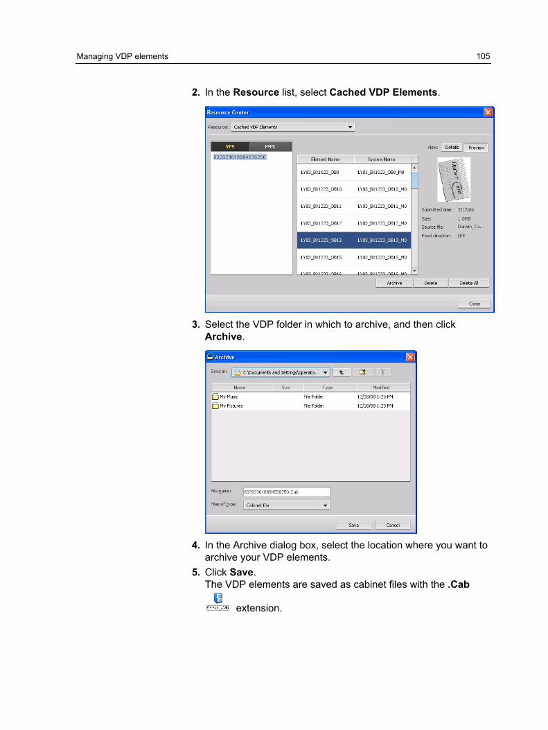
2. In the Resource list, select Cached VDP Elements.
3. Select the VDP folder in which to archive, and then clickArchive.
4. In the Archive dialog box, select the location where you want toarchive your VDP elements.
5. Click Save.The VDP elements are saved as cabinet files with the .Cab
extension.
Managing VDP elements 105

Retrieving VDP elementsWhen you need to reprint your job, you can retrieve your archivedVDP elements.
1. From the File menu, select Retrieve from archive.The Retrieve window appears.
2. Locate the folder in which your VDP elements are archived.
3. Select the desired file and then click the Add (+) button
Note: Use SHIFT or CTRL to select several files or CTRL +A toselect all the files.
4. Click Retrieve.The Color Controller C-80 retrieves the archived VDP elementsand displays them at the end of the file list in the Cached VDPelements dialog box.
Deleting VDP ElementsVDP elements that are no longer in use take up valuable diskspace on the Color Controller C-80. To free up disk space, you candelete the VI elements that you no longer need.
1. From the Tools menu, select Resource Center.2. In the Resource list, select Cached VDP Elements.
Your VDP jobs are listed in the left pane. In the right pane, all ofthe VDP elements that are associated with your job are listed.In addition, a thumbnail viewer lets you check elements visually.
106 Chapter 10—Variable data printing jobs

3. Select the element that you want to delete, and then clickDelete.
Note: You can also delete the entire folder.
Managing VDP elements 107

108 Chapter 10—Variable data printing jobs

11 Job parameters
Print tab in the Job Parameters windowEdit and change print parameters and options for your job.
Parameter Option Description
Copies and Pages Number of copies The number of copies that you want to print.
Pages Print range Provides the following options: All, Odd pages, Evenpages, and Pages.
Note: For VDP jobs, the Pages option changes to Booklets.For imposed jobs, instead of typing the desired pages, typethe desired number of imposed sheets.
You can select specific pages, booklets, or page ranges,specify the pages or booklets to be printed as follows:
● Type one or several numbers separated by commas andno spaces—for example, 1,3,5.
● Type a range of pages or booklets with a hyphenbetween the starting and ending numbers in the range—for example, 1-5.
Print Method Simplex For single-sided printing.
Duplex head to head For printing book-style hard copies (usually used withportrait jobs).
Duplex head to toe For calendar-style hard copies (usually used with landscapejobs).

Parameter Option Description
Print mode The following options are available:
● Composite: (default setting) Prints the job withoutseparations. Each page of the job is printed once.
● Separations: Prints the job with color or grayscaleseparations. If you select color separations, each page inthe job is printed in four colors: cyan, magenta, yellow,and black. If you select grayscale, each page in the job isprinted separately four times in difference shades of gray(K).
● Progressive: Prints each page of the job four times inprogressive color separations.
● Custom: Enables you to select the separations that youwant to print each sheet for each page of the job.
Paper stock The following options are available:
● Paper Stock name: Select the desired paper stock. Ifyou select Undefined, you can set the desiredparameters in the Paper size, Media type, and Mediaweight lists.
● Paper size: The paper size that you want to use. Forcustom paper sizes, you need to specify the requiredwidth and height.
Note: The units of measurement (mm or inches) areselected in the Localization tab in the Preferenceswindow.
● Media type:
The media type that you want to use. When the defaultsetting, Use Printer settings is selected, your job isprinted on the media type that is defined on the printer.
Note: If the selected media type is unavailable, thecurrent job is held until the appropriate set is available(the job receives an on hold status indicator, and amessage appears in the Message Viewer window). Otherjobs can print while jobs are held.
● Media weight:
The media weight that you want to use. When the defaultsetting, Use Printer Settings is selected, your job isprinted on the paper weight that is defined on the printer.
● Mixed paper size: Select check box if the job containsdifferent paper sizes.
Tray The specific stock that you want to use is loaded in this tray.Select Force Tray to force the printer to use the paper stockfrom the tray selected from the list.
110 Chapter 11—Job parameters
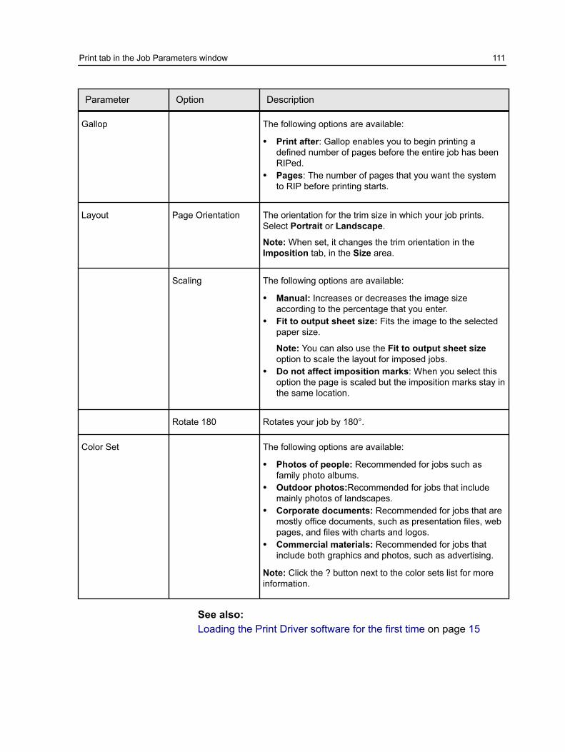
Parameter Option Description
Gallop The following options are available:
● Print after: Gallop enables you to begin printing adefined number of pages before the entire job has beenRIPed.
● Pages: The number of pages that you want the systemto RIP before printing starts.
Layout Page Orientation The orientation for the trim size in which your job prints.Select Portrait or Landscape.
Note: When set, it changes the trim orientation in theImposition tab, in the Size area.
Scaling The following options are available:
● Manual: Increases or decreases the image sizeaccording to the percentage that you enter.
● Fit to output sheet size: Fits the image to the selectedpaper size.
Note: You can also use the Fit to output sheet sizeoption to scale the layout for imposed jobs.
● Do not affect imposition marks: When you select thisoption the page is scaled but the imposition marks stay inthe same location.
Rotate 180 Rotates your job by 180°.
Color Set The following options are available:
● Photos of people: Recommended for jobs such asfamily photo albums.
● Outdoor photos:Recommended for jobs that includemainly photos of landscapes.
● Corporate documents: Recommended for jobs that aremostly office documents, such as presentation files, webpages, and files with charts and logos.
● Commercial materials: Recommended for jobs thatinclude both graphics and photos, such as advertising.
Note: Click the ? button next to the color sets list for moreinformation.
See also:Loading the Print Driver software for the first time on page 15
Print tab in the Job Parameters window 111
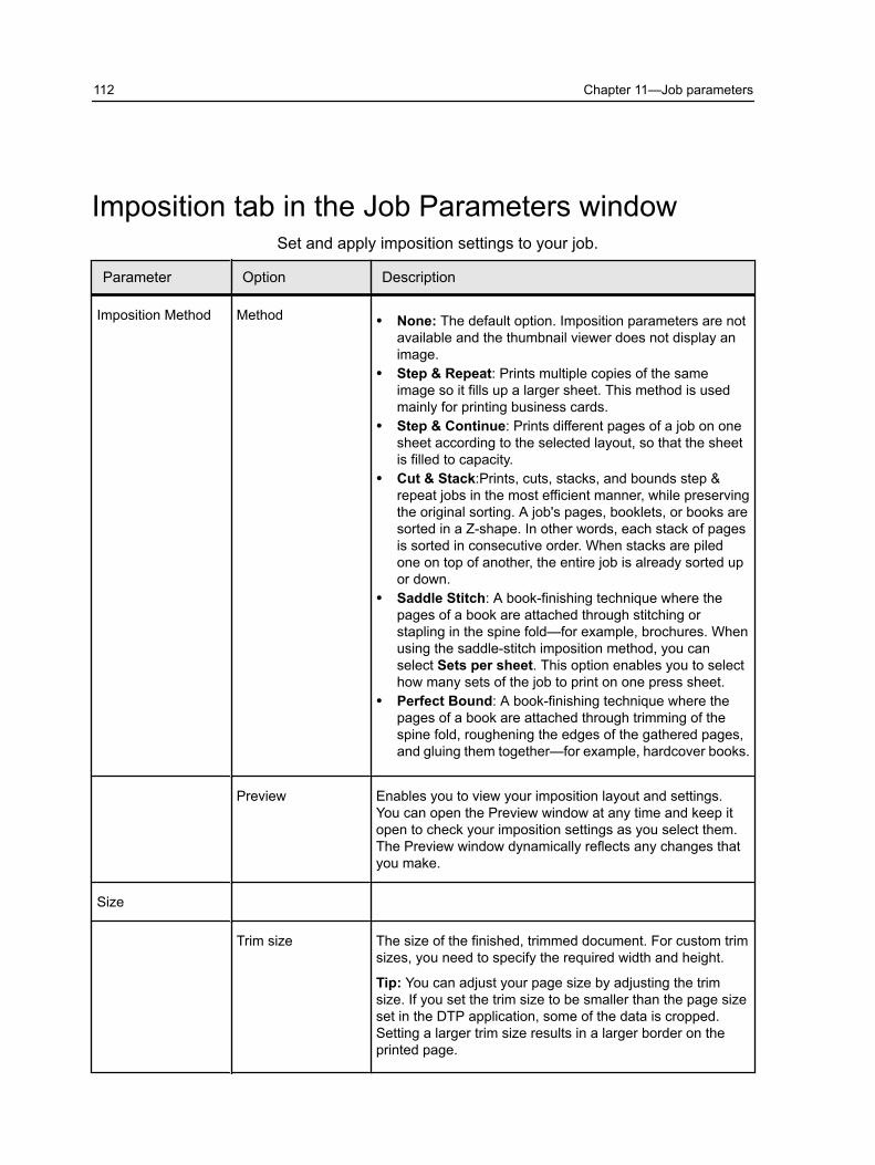
Imposition tab in the Job Parameters windowSet and apply imposition settings to your job.
Parameter Option Description
Imposition Method Method ● None: The default option. Imposition parameters are notavailable and the thumbnail viewer does not display animage.
● Step & Repeat: Prints multiple copies of the sameimage so it fills up a larger sheet. This method is usedmainly for printing business cards.
● Step & Continue: Prints different pages of a job on onesheet according to the selected layout, so that the sheetis filled to capacity.
● Cut & Stack:Prints, cuts, stacks, and bounds step &repeat jobs in the most efficient manner, while preservingthe original sorting. A job's pages, booklets, or books aresorted in a Z-shape. In other words, each stack of pagesis sorted in consecutive order. When stacks are piledone on top of another, the entire job is already sorted upor down.
● Saddle Stitch: A book-finishing technique where thepages of a book are attached through stitching orstapling in the spine fold—for example, brochures. Whenusing the saddle-stitch imposition method, you canselect Sets per sheet. This option enables you to selecthow many sets of the job to print on one press sheet.
● Perfect Bound: A book-finishing technique where thepages of a book are attached through trimming of thespine fold, roughening the edges of the gathered pages,and gluing them together—for example, hardcover books.
Preview Enables you to view your imposition layout and settings.You can open the Preview window at any time and keep itopen to check your imposition settings as you select them.The Preview window dynamically reflects any changes thatyou make.
Size
Trim size The size of the finished, trimmed document. For custom trimsizes, you need to specify the required width and height.
Tip: You can adjust your page size by adjusting the trimsize. If you set the trim size to be smaller than the page sizeset in the DTP application, some of the data is cropped.Setting a larger trim size results in a larger border on theprinted page.
112 Chapter 11—Job parameters
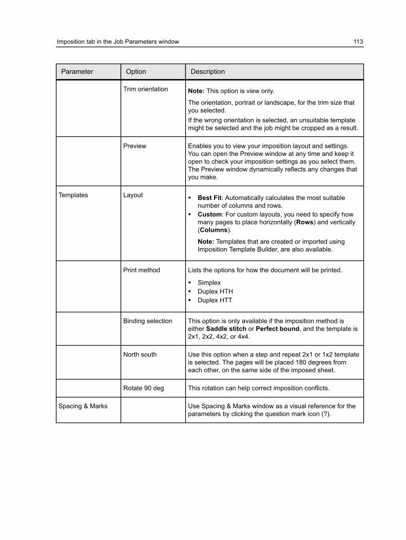
Parameter Option Description
Trim orientation Note: This option is view only.
The orientation, portrait or landscape, for the trim size thatyou selected.If the wrong orientation is selected, an unsuitable templatemight be selected and the job might be cropped as a result.
Preview Enables you to view your imposition layout and settings.You can open the Preview window at any time and keep itopen to check your imposition settings as you select them.The Preview window dynamically reflects any changes thatyou make.
Templates Layout ● Best Fit: Automatically calculates the most suitablenumber of columns and rows.
● Custom: For custom layouts, you need to specify howmany pages to place horizontally (Rows) and vertically(Columns).
Note: Templates that are created or imported usingImposition Template Builder, are also available.
Print method Lists the options for how the document will be printed.
● Simplex● Duplex HTH● Duplex HTT
Binding selection This option is only available if the imposition method iseither Saddle stitch or Perfect bound, and the template is2x1, 2x2, 4x2, or 4x4.
North south Use this option when a step and repeat 2x1 or 1x2 templateis selected. The pages will be placed 180 degrees fromeach other, on the same side of the imposed sheet.
Rotate 90 deg This rotation can help correct imposition conflicts.
Spacing & Marks Use Spacing & Marks window as a visual reference for theparameters by clicking the question mark icon (?).
Imposition tab in the Job Parameters window 113

Parameter Option Description
Marks ● Crop marks: Prints the lines that indicate where thesheet should be cropped. The Both Sides check boxprints crop marks on both sides of the page.
Notes:
❐ If you want to use crop marks incorporated in theDTP application, make sure that enough space is leftaround your page in the PostScript file so that thepage prints with crop marks.
❐ If your job already includes crop marks incorporatedin the DTP application, you do not need to add cropmarks here. If you do add crop marks, both sets ofcrop marks can be printed.
● Fold marks: Prints the lines that indicate where thesheet should be folded. This is only available withSaddle stitch or Perfect bound.
● Crop & fold marks: Prints the lines that indicate wherethe sheet should be folded. This is only available withSaddle stitch or Perfect bound.
Margins The value entered adjusts the spaces between the outsideedges of pages and the edges of the sheet on which theyare printed.
Notes:
● Margin settings should suit finishing equipment andrequirements.
● Confirm binding parameters with your binder whenplanning your sheet.
Gutter The value that you enter depends on the paper size andimposition method that you choose.
The gutter size is the space between pairs of pages(according to the trim size) on a sheet. When the pages arefolded into a booklet, the gutter allows space for trimming.
Spine The value that you enter depends on the paper size andimposition method that you choose. This is only availablewith Perfect bound.
114 Chapter 11—Job parameters
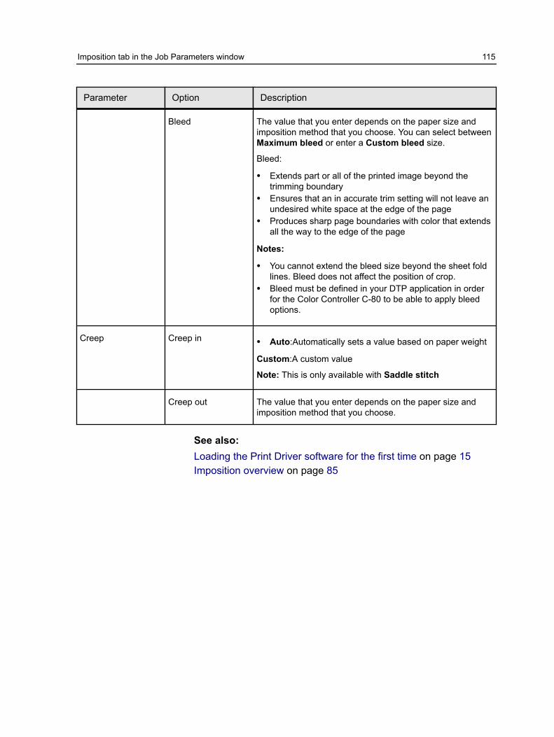
Parameter Option Description
Bleed The value that you enter depends on the paper size andimposition method that you choose. You can select betweenMaximum bleed or enter a Custom bleed size.
Bleed:
● Extends part or all of the printed image beyond thetrimming boundary
● Ensures that an in accurate trim setting will not leave anundesired white space at the edge of the page
● Produces sharp page boundaries with color that extendsall the way to the edge of the page
Notes:
● You cannot extend the bleed size beyond the sheet foldlines. Bleed does not affect the position of crop.
● Bleed must be defined in your DTP application in orderfor the Color Controller C-80 to be able to apply bleedoptions.
Creep Creep in ● Auto:Automatically sets a value based on paper weight
Custom:A custom value
Note: This is only available with Saddle stitch
Creep out The value that you enter depends on the paper size andimposition method that you choose.
See also:Loading the Print Driver software for the first time on page 15Imposition overview on page 85
Imposition tab in the Job Parameters window 115

Quality tab in the Job Parameters windowApply settings to your job to improve the quality of image and textelements in your job.
Parameter Option Description
Image/GraphicsQuality
Image quality ● High: Improves the quality of low resolution images in ajob.
● Normal: Processes the image in the job according to thestandard resolution of the press.
The High option improves the quality of images in a job.
Image quality refers to the ability to maintain the samedetail and smoothness with different degrees ofenlargement. This feature is especially useful when yourPostScript file includes several images with differentqualities—for example, images that were scanned atdifferent resolutions, were rotated, or downloaded fromthe Internet.
Improve Text/Line inImage
Significantly improves the text and line quality in your job. Insome cases, images in the PDL file contain data that belongto the LW layer, such as screen captures and hi-resrasterized text. The Color Controller C-80 is able to identifysuch images and convert them into the line work layer.
Smooth Gradients Select to smooth and blend vignettes of continuous tone(CT) images.
116 Chapter 11—Job parameters

Parameter Option Description
Trapping Enable Trapping Applies trapping to your job.
Trapping is a solution that solves misregistration betweencolor separations in both offset and digital printing. Thisoccurs no matter the accuracy of the printing device, andresults in white lines around objects on top of a background(in a knock-out procedure) and also between adjacent colors.
Note: If you don't select this option, it does not affecttrapping incorporated by DTP applications—for example,Photoshop. FAF should not be used with application-basedtrapping. In a PostScript file that already contains trappingfrom the originating application, it is not necessary to useColor Controller C-80 trapping.
Frame thickness: The desired value for the thickness ofthe trapping frame. The thicker the frame, the less chancethat white areas appear between images.
Protect small text: Text that is smaller or equal to 12 pt. isprotected and not framed when the FAF algorithm isapplied. You can use this option for small or compleximages, since thicker frames can decrease quality by hidingparts of an image.
Overprint Black overprint Ensures that black text prints cleanly within a tint or picturearea. The text appears in a richer, deeper black, with theunderlying CMY values equal to those of the printedbackground.
PostScript overprint Uses the overprint information that exists in the PostScriptfile. This parameter also determines whether the DTPapplication PostScript overprint settings are honored in theRIP.
Screening Screening converts CT (Continuous Tone) and LW (LineWork) images into information (halftone dots) that can beprinted. The human eye “smooths out” this information,which seems visually consistent with the original picture.Thus, the more lines per inch, the more natural the imageappears. Screening is achieved by printing dots innumerous shapes or lines in an evenly spaced pattern. Thedistance between the screen dots or lines is fixed anddetermines the quality of the image. Printers can work witheven amounts of toner and still produce a wide range ofcolors when you use screening. The darker the color, thelarger the dot.
In order to print an image on a digital printer or press thecolor server needs to digitally approximate the grayscalevalues with different distributions of black and white pixels.This process is commonly referred to as half-toning. Digitalhalftoning begins by sampling the original image at theprinter dpi and constructing digital halftone cells.
Quality tab in the Job Parameters window 117

Parameter Option Description
175 Dot Applies a medium dot-type screen. The screen of eachseparation is printed at a different angle.
200 Dot Applies a high dot-type screen. The screen of eachseparation is printed at a different angle.
200 Dot + 250 Linefor Text
Applies a high dot-type screen. The screen of eachseparation is printed at a different angle. In addition appliesa high lpi line-type screen for text elements.
200 Dot + 250 Linefor Text/Graphics
Applies a high dot-type screen. The screen of eachseparation is printed at a different angle. In addition appliesa high lpi line-type screen for text and graphic elements.
200 Line Applies a high lpi line-type screen. The screen of eachseparation is printed at a different angle.
250 Line Applies a high lpi line-type screen. The screen of eachseparation is printed at a different angle.
FM FM screening is sometimes called stochastic screeningbecause the placement appears to be random, although dotplacement is precisely controlled by sophisticatedmathematical algorithms.
See also:Loading the Print Driver software for the first time on page 15
118 Chapter 11—Job parameters

Color tab in the Job Parameters windowApply various color settings and options to improve the colorquality of your job.
Parameter Option Description
Color Mode Grayscale Prints the job as black and white using black (K) toner only.The cyan (C), magenta (M), and yellow (Y) separations arealso printed in black (K) toner, giving a dense appearancesimilar to the CMYK grayscale image.
Note: Grayscale images created in RGB applications, suchas PowerPoint, should be specified as Monochrome orsubmitted to the system with Grayscale selected in thePPD file. This selection ensures that grayscale images arecounted as black and white instead of color in both theColor Controller C-80 and in the printer billing meters.
CMYK Prints the job in color using the cyan, magenta, yellow andblack inks . This is the color mode set for printing all jobs.
Color Adjustments Brightness The brightness level for the print job. The range starts fromLightest, which applies -15%, to Darkest, which applies +15.
Brightness is generally used to make last-minuteadjustments to the print job after proofing. By changing theBrightness setting, you can control how light or dark youroutput will appear.
Contrast Contrast is generally used to make last-minute adjustmentsto the print job after proofing. By adjusting the Contrastsetting, you can control the difference between the lighttones and the dark tones in your image.
Color tab in the Job Parameters window 119
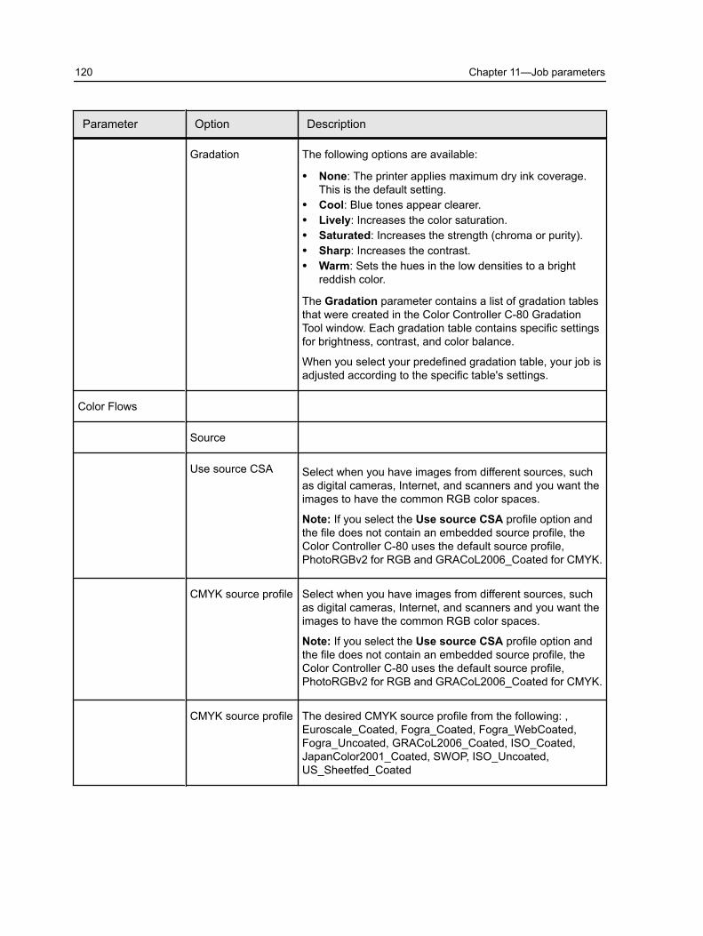
Parameter Option Description
Gradation The following options are available:
● None: The printer applies maximum dry ink coverage.This is the default setting.
● Cool: Blue tones appear clearer.● Lively: Increases the color saturation.● Saturated: Increases the strength (chroma or purity).● Sharp: Increases the contrast.● Warm: Sets the hues in the low densities to a bright
reddish color.
The Gradation parameter contains a list of gradation tablesthat were created in the Color Controller C-80 GradationTool window. Each gradation table contains specific settingsfor brightness, contrast, and color balance.
When you select your predefined gradation table, your job isadjusted according to the specific table's settings.
Color Flows
Source
Use source CSA Select when you have images from different sources, suchas digital cameras, Internet, and scanners and you want theimages to have the common RGB color spaces.
Note: If you select the Use source CSA profile option andthe file does not contain an embedded source profile, theColor Controller C-80 uses the default source profile,PhotoRGBv2 for RGB and GRACoL2006_Coated for CMYK.
CMYK source profile Select when you have images from different sources, suchas digital cameras, Internet, and scanners and you want theimages to have the common RGB color spaces.
Note: If you select the Use source CSA profile option andthe file does not contain an embedded source profile, theColor Controller C-80 uses the default source profile,PhotoRGBv2 for RGB and GRACoL2006_Coated for CMYK.
CMYK source profile The desired CMYK source profile from the following: ,Euroscale_Coated, Fogra_Coated, Fogra_WebCoated,Fogra_Uncoated, GRACoL2006_Coated, ISO_Coated,JapanColor2001_Coated, SWOP, ISO_Uncoated,US_Sheetfed_Coated
120 Chapter 11—Job parameters

Parameter Option Description
CMYK renderingintent
Rendering intent enables you to compress out-of-gamutcolors into the color capability of the press you are using.The desired rendering intent should be selected to preservethe important aspects of the elements and applied to RGBand CMYK elements.
All printers, monitors and scanners have a gamut or rangeof colors that they can output (or view in the case of ascanner). If a color needs to be output and is outside thegamut of the output device, it must be mapped orapproximated to some other color, which exists within thegamut. Rendering Intent enables you to compress out-of-gamut colors into the color capability of the press you areusing. You can set any rendering intent value for RGBelements by selecting the required from the Renderingintent options list. The default value for RGB is Perceptual(photographic). The default value for CMYK is RelativeColorimetric.
There are several methods that can be used whentranslating colors from one color space to another. Thesemethods are called Rendering Intents because they areoptimized for various uses. When working with ICC profiles,it is important that you select the Rendering Intent that bestpreserves the important aspects of the image. Eachrendering method specifies a CRD for color conversions.You can modify the rendering method to control theappearance of images, such as prints from Microsoft Officesoftware or RGB photographs from Photoshop software.The following options are available:
● Auto: Automatically applies different rendering intents toeach object type (images, text, and graphics). Use thisoption when your file includes different objects on thesame page—for example, a presentation that includesjpg pictures, text, and Microsoft Excel graphs. If RGBimages and CMYK graphic elements are included on thesame page, the RGB images will use perceptualrendering intent, while the CMYK graphic elements willuse relative rendering intent.
Note: Preserve pure CMY colors is not affected by thisrendering intent option.
● Relative colorimetric: Some closely related colors inthe input color space can be mapped to the closestpossible color in the output color space. This reduces thenumber of colors in the image.
● Absolute colorimetric: Select this method forrepresenting “signature colors“. Colors that are highlyidentified with a commercial product. Colors that fallinside the output color space are matched very accurately.
● Saturation: Select this method for artwork and graphs inpresentations. In many cases, this option can be used
Color tab in the Job Parameters window 121

Parameter Option Description
for mixed pages that contain both presentation graphicsand photographs.
Note: Select Saturation to achieve smoothness whenyou print RGB vector graphics (non image).
● Perceptual: Select this method when working withrealistic images such as photographs, including scansand images from stock photography CDs. All or mostcolors in the original are changed but the relationshipbetween them does not change.
Emulate sourcepaper tint
Emulates the original paper tint if it is included in the profile.
Notes:
● You cannot select Preserve pure CMY colors whenselecting Emulate source paper tint.
● If the job is simplex, only the front side will be printedusing the tint emulation.
● When the check box is selected, Absolute Colorimetricwill be used as the rendering method.
RGB source profile The desired RGB source profile from the following:AdobeRGB1998, AppleRGB, ColorMatchRGB,SourceRGB_1.8, SourceRGB_2.1, SourceRGB_2.4, sRGB,PhotoRGB, PhotoRGB_Outdoors, PhotoRGB_People
RGB rendering intent The following options are available, refer to the descriptionunder CMYK rendering intent for an explanation on eachoption:
● Auto● Relative colorimetric● Absolute colorimetric● Saturation● Perceptual
Apply CMYKemulation
To convert RGB elements according to the selected CMYKemulation method, select the Apply CMYK emulation. TheRGB elements receive the same look as the CMYKelements, creating a unified appearance.
Destination Profile The following options are available:
● Linked: Uses the destination profile that was linked usingthe Media and Color Manager in the Resource Center.
● ProC900_Plain_CreoVI: TBD● ProC900_GlossThick_CreoV1: TBD● ProC900_CoatedMatte_CreoV1: TBD● ProC900_CoatedGloss_CreoV1: TBD
122 Chapter 11—Job parameters
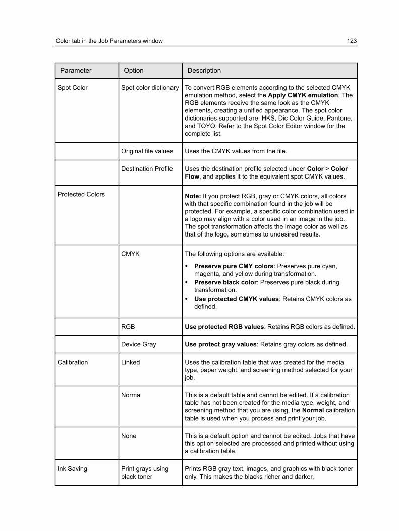
Parameter Option Description
Spot Color Spot color dictionary To convert RGB elements according to the selected CMYKemulation method, select the Apply CMYK emulation. TheRGB elements receive the same look as the CMYKelements, creating a unified appearance. The spot colordictionaries supported are: HKS, Dic Color Guide, Pantone,and TOYO. Refer to the Spot Color Editor window for thecomplete list.
Original file values Uses the CMYK values from the file.
Destination Profile Uses the destination profile selected under Color > ColorFlow, and applies it to the equivalent spot CMYK values.
Protected Colors Note: If you protect RGB, gray or CMYK colors, all colorswith that specific combination found in the job will beprotected. For example, a specific color combination used ina logo may align with a color used in an image in the job.The spot transformation affects the image color as well asthat of the logo, sometimes to undesired results.
CMYK The following options are available:
● Preserve pure CMY colors: Preserves pure cyan,magenta, and yellow during transformation.
● Preserve black color: Preserves pure black duringtransformation.
● Use protected CMYK values: Retains CMYK colors asdefined.
RGB Use protected RGB values: Retains RGB colors as defined.
Device Gray Use protect gray values: Retains gray colors as defined.
Calibration Linked Uses the calibration table that was created for the mediatype, paper weight, and screening method selected for yourjob.
Normal This is a default table and cannot be edited. If a calibrationtable has not been created for the media type, weight, andscreening method that you are using, the Normal calibrationtable is used when you process and print your job.
None This is a default option and cannot be edited. Jobs that havethis option selected are processed and printed without usinga calibration table.
Ink Saving Print grays usingblack toner
Prints RGB gray text, images, and graphics with black toneronly. This makes the blacks richer and darker.
Color tab in the Job Parameters window 123

Parameter Option Description
Total Ink Coverage Ink Limiting: Reduces that amount of ink coverage printedon your job. You can select either Normal or Low.
Note: Low reduces the amount of ink more than Normal.
Ink Saving GCR: Conserves toner by replacing the gray component(CMY) of pixels with black toner.
Selecting Normal gives you a smoother image quality.Selecting High, gives you a less smooth image quality(adds black into flesh tones).
The gray component replacement also prevents theconsequences of excessive toner buildup, such as flakingand cracking , or the "curling" effect that may occur whenprinting transparencies.
While the gray component of each color is replaced byblack, there is no change in the color quality of the printedimage.
Print grays usingblack toner
Prints RGB gray text, images, and graphics with black toneronly. This makes the blacks richer and darker. You canselect to apply For text and graphics or For text,graphics, and images. In addition, you can Apply onlywhen R, G, B values are the same.
See also:Loading the Print Driver software for the first time on page 15
Photo touch-up tab in the Job Parameters windowThe Photo Touch-up option is only available with the ProcessPower Pack.
Parameter Option Description
Exposure andcolor cast
Corrects underexposure, overexposure,and minor color-cast problems in photos.
Image noise Reduces noise (such as granularitycaused by high ISO settings) in a photo.
Shadows andhighlights
Brings out details in the dark and lightareas of a photo.
124 Chapter 11—Job parameters
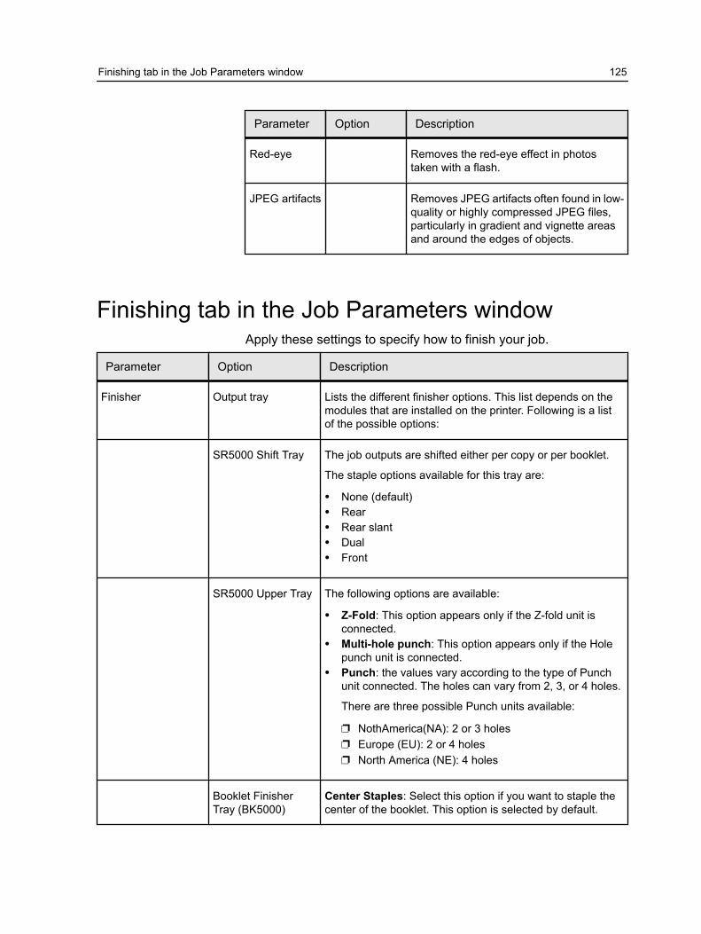
Parameter Option Description
Red-eye Removes the red-eye effect in photostaken with a flash.
JPEG artifacts Removes JPEG artifacts often found in low-quality or highly compressed JPEG files,particularly in gradient and vignette areasand around the edges of objects.
Finishing tab in the Job Parameters windowApply these settings to specify how to finish your job.
Parameter Option Description
Finisher Output tray Lists the different finisher options. This list depends on themodules that are installed on the printer. Following is a listof the possible options:
SR5000 Shift Tray The job outputs are shifted either per copy or per booklet.
The staple options available for this tray are:
● None (default)● Rear● Rear slant● Dual● Front
SR5000 Upper Tray The following options are available:
● Z-Fold: This option appears only if the Z-fold unit isconnected.
● Multi-hole punch: This option appears only if the Holepunch unit is connected.
● Punch: the values vary according to the type of Punchunit connected. The holes can vary from 2, 3, or 4 holes.
There are three possible Punch units available:
❐ NothAmerica(NA): 2 or 3 holes❐ Europe (EU): 2 or 4 holes❐ North America (NE): 4 holes
Booklet FinisherTray (BK5000)
Center Staples: Select this option if you want to staple thecenter of the booklet. This option is selected by default.
Finishing tab in the Job Parameters window 125

Parameter Option Description
Perfect Binder Tray The following options are available:
● Pull Cover from: Select either the Perfect BinderInterposer upper or lower tray.
● Binding: Select either Left, Right, Top, Bottom. Left isthe default.
There are additional settings that you can select in order totrim the job. Select Trim Job and click Settings for theavailable trim options.
Ring Binder Tray There are two options available when this unit is connectedto the printer:
● Ring Bind (default)● Punch only
Booklet ProcessorTray
This finisher unit enables you to staple, square fold, and trimthe edge of the job. The user can not control this finisherfrom the Color Controller.
Stacker Upper Tray Includes the Multi Hole Punch option (same as defined forthe SR5000 Upper Tray).
Stacker Tray The following options are available:
● Offset● Multi Hole Punch● Print sample every x copies. the sample is printed to the
upper tray.● Sheet range: You can select either to print all the sheets
or a range of sheets within a job.
Configurationdependency
Following is important information regarding the differentcombinations of finisher options.
Two stacker finishers If two stacker finishers are installed (without the SR5000),the following trays are available:
● Stacker upper tray (closer to the engine)● Stacker Tray● Second Stacker Tray.
Note: The Second Stacker Upper Tray is not available.
126 Chapter 11—Job parameters

Parameter Option Description
One Stackers andSR5000
If one stacker finisher and SR5000 are installed, thefollowing trays are available:
● Stacker Upper Tray● Stacker Tray● SR5000 Shift Tray.
Note: The SR5000 Upper Tray is not available.
Two Stackers andSR5000
If two Stacker finishers and SR5000 are installed, thefollowing trays are available:
● Stacker Upper Tray● Stacker Tray● Second Stacker Tray● SR5000 Shift Tray.
Note: SR5000 Upper tray and Second Stacker Upper Trayare not available.
Booklet Processorand SR5000
If the Booklet Processor and SR5000 are installed, thefollowing trays are available:
● SR5000 Upper Tray● Booklet Processor Tray
Near-Line Finisher Device Select the devices in your finishing configuration.
DSF-2000 Select to use sheet feeder, which is configured with abarcode reader.
Duplo DC-645 Select to use Duplo DC-645 finisher to cut, slit, and creasedocuments using registration marks and barcodes.
Note: A barcode is used only if you want to use a presetJob number. Otherwise you can select it manually on theDuplo DC-645.
Position Select one of the following for the position to generate thebarcode: Top right, Top left, Bottom right, and Bottom left
Side Select the side where the barcode will be generated. SelectFront side or Back side
Registration lineoffset
Paper feed direction: the whole registration mark should bewithin 3 mm - 20 mm from the lead edge. Paper widthdirection: the whole registration mark should be within 3 mm-20 mm from the right edge.
Note: This option is available for the DC-645.
Finishing tab in the Job Parameters window 127
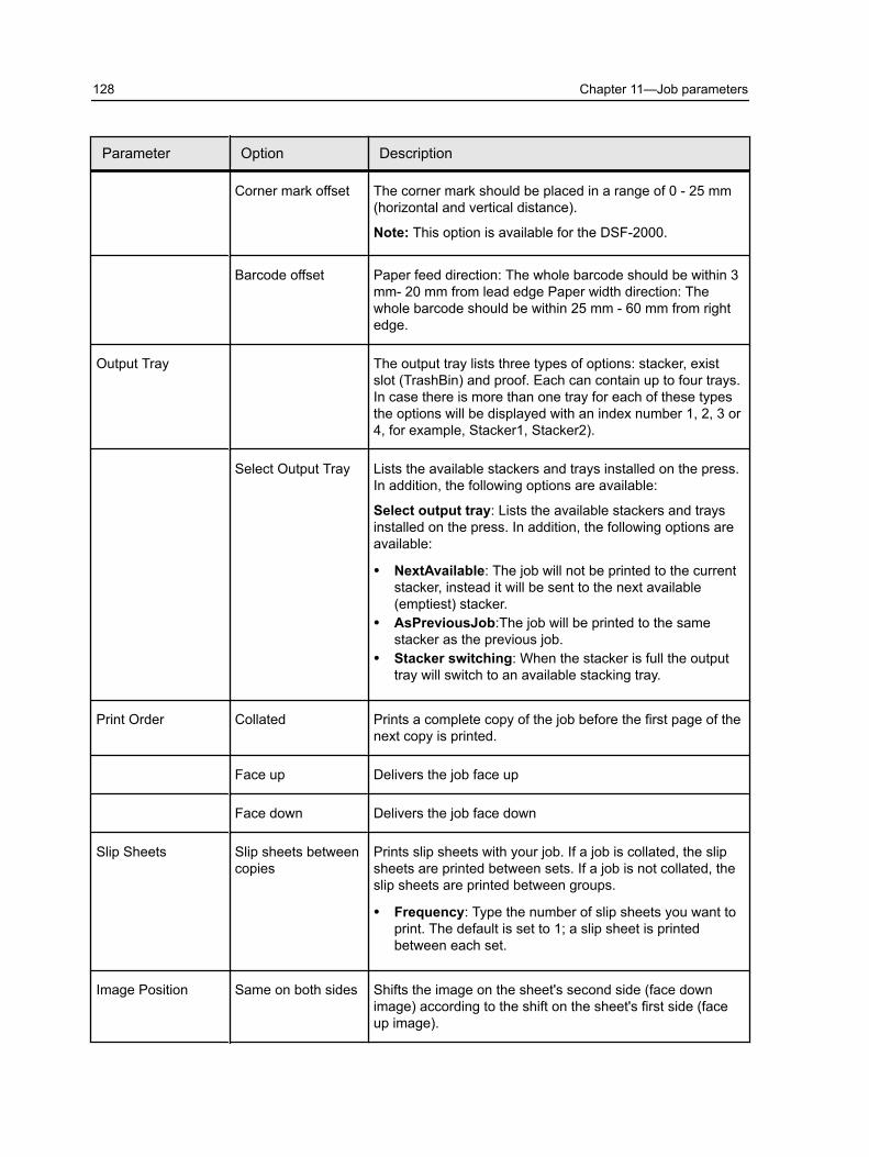
Parameter Option Description
Corner mark offset The corner mark should be placed in a range of 0 - 25 mm(horizontal and vertical distance).
Note: This option is available for the DSF-2000.
Barcode offset Paper feed direction: The whole barcode should be within 3mm- 20 mm from lead edge Paper width direction: Thewhole barcode should be within 25 mm - 60 mm from rightedge.
Output Tray The output tray lists three types of options: stacker, existslot (TrashBin) and proof. Each can contain up to four trays.In case there is more than one tray for each of these typesthe options will be displayed with an index number 1, 2, 3 or4, for example, Stacker1, Stacker2).
Select Output Tray Lists the available stackers and trays installed on the press.In addition, the following options are available:
Select output tray: Lists the available stackers and traysinstalled on the press. In addition, the following options areavailable:
● NextAvailable: The job will not be printed to the currentstacker, instead it will be sent to the next available(emptiest) stacker.
● AsPreviousJob:The job will be printed to the samestacker as the previous job.
● Stacker switching: When the stacker is full the outputtray will switch to an available stacking tray.
Print Order Collated Prints a complete copy of the job before the first page of thenext copy is printed.
Face up Delivers the job face up
Face down Delivers the job face down
Slip Sheets Slip sheets betweencopies
Prints slip sheets with your job. If a job is collated, the slipsheets are printed between sets. If a job is not collated, theslip sheets are printed between groups.
● Frequency: Type the number of slip sheets you want toprint. The default is set to 1; a slip sheet is printedbetween each set.
Image Position Same on both sides Shifts the image on the sheet's second side (face downimage) according to the shift on the sheet's first side (faceup image).
128 Chapter 11—Job parameters

Parameter Option Description
Rear The sheet's edge near the printer rear, where printing stops.
Lead The edge of a sheet at which printing begins.
Tip: Use this option to move duplex page data away fromthe spine.
Center Prints your job in the center of the page.
See also:Loading the Print Driver software for the first time on page 15
Exceptions tab in the Job Parameters windowParameter Option Description
Type Here you can define which type of exception to apply toyour document. You can select a range of pages, front andback covers, and inserts.
Paper stock Select the media type for the pages you want to apply theexception.
Tray The destination tray for the output.
Advanced Options
Destination profile Select either the same destination selected for this job orfrom the list of available destination profiles.
Exceptions tab in the Job Parameters window 129

Parameter Option Description
Z-fold Select either On or Off to apply Z-fold to this exception.
Image Position The following options are available:
● Same as job: This options allows you to have the imageposition be the same as the rest of the job .
● Same on Both Sides: Shift the image on the secondside of the sheet according to the image shift on the firstside of the sheet .
● You can also manually define the shift for odd and evenpages. In addition you can set the pages to center on thepaper.
Services tab in the Job Parameters windowEnables you to set job parameters that will assist your jobworkflow on this tab, you can set deletion policies for completedand failed jobs perform a preflight check on key components, setfont substitution preference, and apply the automatic picturereplacement (APR) mechanism. On this tab, you can set a jobflow, add information to your Job Info items and split a PostScriptfile into booklets to simulate a VI job structure. In this tab, you canalso activate a special workflow that decreases significantly theprocessing time for PDF and PostScript files with repeatedelements.
Parameter Option Description
Admin page The administration page contains job-related informationsuch as the job title, page size, number of pages or sets,and the sender name.
The administration page is printed in the same order as thejob, for face-down printing, the page is printed before eachset and for face-up printing, the page is printed after each set.
Note: If you change the options in the Admin pageparameter, the job needs to be re-RIPed.
Job Flow Defines the flow the job associated with this job ticketfollows when submitted to the Color Controller C-80.
Print RIPs, prints, and stores the PDL files in the Storage area(unless the Job Deletion parameter is set to Delete printedjobs from storage).
130 Chapter 11—Job parameters

Parameter Option Description
Process RIPs and moves the PDL files to the Storage area as RTPjobs.
Store Places the PDL files directly into the Storage area withoutprocessing them.
Job Deletion Delete printed jobsfrom storage
Removes pages or jobs from the Color Controller C-80 afterprinting is completed.
Delete failed jobsfrom storage
Removes failed jobs while processing or printing from theColor Controller C-80.
Notes:
● The Delete failed jobs from storage option sustainsenough free disk space for the duration of the print runand only affects the sub-job.
● The Variable Print Specification file is also deleted.
Font Substitution Use FontSubstitution
Substitutes a missing font with the default font that is set inthe Resource Center.
Notes:
● If a font is substituted, a message appears in the JobHistory window.
● You can only substitute Latin fonts.
PDF/PostScriptOptimizations
PostScriptoptimization
Significantly decreases processing time in PostScript jobswith repeated elements by applying the PS workflow.
PDF optimization Significantly decreases processing time in PDF jobs withrepeated elements by applying the PDF workflow.
Preflight Run preflight Checks the status of key job components before the job issent for printing.
Your job is RIPed and the missing components are identified.
Split to Booklet Split to Booklets Splits a PostScript, PDF, or large VI job that does not havea booklet structure into booklets.
Note: Unexpected results might occur when you use thisoption for VDP jobs that already have a booklet structure.
Number of pagesper booklet
The desired number of booklets.
Note: If the specified number of pages per booklet is notsufficient to produce complete booklets and there is aremainder of pages, the last pages will form a booklet thatcontains less pages than specified.
Services tab in the Job Parameters window 131

Parameter Option Description
APR/OPI High resolutionimages
Replaces low-resolution images in your job with high-resolution images that are located in a specified APR or OPIpath.
Low resolutionimages
Prints the job with the existing low-resolution images—forexample, for proofing purposes.
Job Slug Prints a slug in the margins of your job with the selectedoptions.
Note: This option is only available with the ProfessionalPower Pack.
Color bar Prints a measurable color bar. Looking at this bar, you cantell the state of the printer and whether the quality isconsistent. You might need to calibrate the Pro C900 orperform color proofing.
Job name The Job name is printed in the margin of the sheets within ajob.
Sheet number andside (front/back)
The the sheet number and side is printed in the margin ofthe sheets within a job.
Date and time The date and time is printed in the margin of the sheetswithin a job.
ISO conformancelevel
The ISO conformance level is printed in the margin of thesheets within a job. For example: Validation Print accordingto ISO 12647-7.
Printer description The name and model of the printer is printed in the marginof the sheets within a job.
Color serverdescription
The name and model of the color server is printed in themargin of the sheets within a job.
Colorant and media The paper stock, paper size and media type is printed in themargin of the sheets within a job. In addition, the color modeis also printed.
Color profiles The profiles selected in the job parameters window isprinted in the margin of the sheets within a job.
Calibration date The last calibration date is printed in the margin of thesheets within a job. For Example: Last Calibration Date: 26Nov 2008, 15:21
132 Chapter 11—Job parameters

Parameter Option Description
Comment Adds comments containing up to 30 characters.
Job Info Job title Original name of the file related to this job.
Sender User name of the system from which this job originated.
Account Account number of a specific customer or group.
Recipient Name of customer.
Job comments Any special instructions that you want to include with your job.
Job link Displays the relevant URL for the linked elements of JDF jobs.
See also:Loading the Print Driver software for the first time on page 15
Services tab in the Job Parameters window 133

134 Chapter 11—Job parameters

12 Setting up your colorserver
The Preferences windowThis window contains several tools that enable you to manage yoursystem and resources. Most of these settings are configuredduring the First Time Setup. You should consult with the siteadministrator before changing any of the server and networksettings. To access the Preferences window, from the File menu,select Preferences.
Option Description
Server Setup Displays the computer (host name) name of the ColorController C-80 and current date and time. The ColorController C-80 is configured at the factory with a defaultgeneric computer and host name. Click Change if you wantto adjust these settings.
Network Setup Displays the TCP/IP and AppleTalk settings. Click Change ifyou want to adjust these settings.
Remote Tools Setup The Remote Tools Setup parameter enables you to connectfrom your computer to the Color Controller C-80 over thenetwork using the Remote Site Manager.
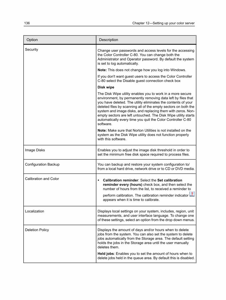
Option Description
Security Change user passwords and access levels for the accessingthe Color Controller C-80. You can change both theAdministrator and Operator password. By default the systemis set to log automatically.
Note: This does not change how you log into Windows.
If you don't want guest users to access the Color ControllerC-80 select the Disable guest connection check box
Disk wipe
The Disk Wipe utility enables you to work in a more secureenvironment, by permanently removing data left by files thatyou have deleted. The utility eliminates the contents of yourdeleted files by scanning all of the empty sectors on both thesystem and image disks, and replacing them with zeros. Non-empty sectors are left untouched. The Disk Wipe utility startsautomatically every time you quit the Color Controller C-80software.
Note: Make sure that Norton Utilities is not installed on thesystem as the Disk Wipe utility does not function properlywith this software.
Image Disks Enables you to adjust the image disk threshold in order toset the minimum free disk space required to process files.
Configuration Backup You can backup and restore your system configuration to/from a local hard drive, network drive or to CD or DVD media.
Calibration and Color ● Calibration reminder: Select the Set calibrationreminder every (hours) check box, and then select thenumber of hours from the list, to received a reminder to
perform calibration. The calibration reminder indicator appears when it is time to calibrate.
Localization Displays local settings on your system, includes, region, unitmeasurements, and user interface language. To change oneof these settings, select an option from the drop down menus.
Deletion Policy Displays the amount of days and/or hours when to deletejobs from the system. You can also set the system to deletejobs automatically from the Storage area. The default settingholds the jobs in the Storage area until the user manuallydeletes them.
Held jobs: Enables you to set the amount of hours when todelete jobs held in the queue area. By default this is disabled.
136 Chapter 12—Setting up your color server
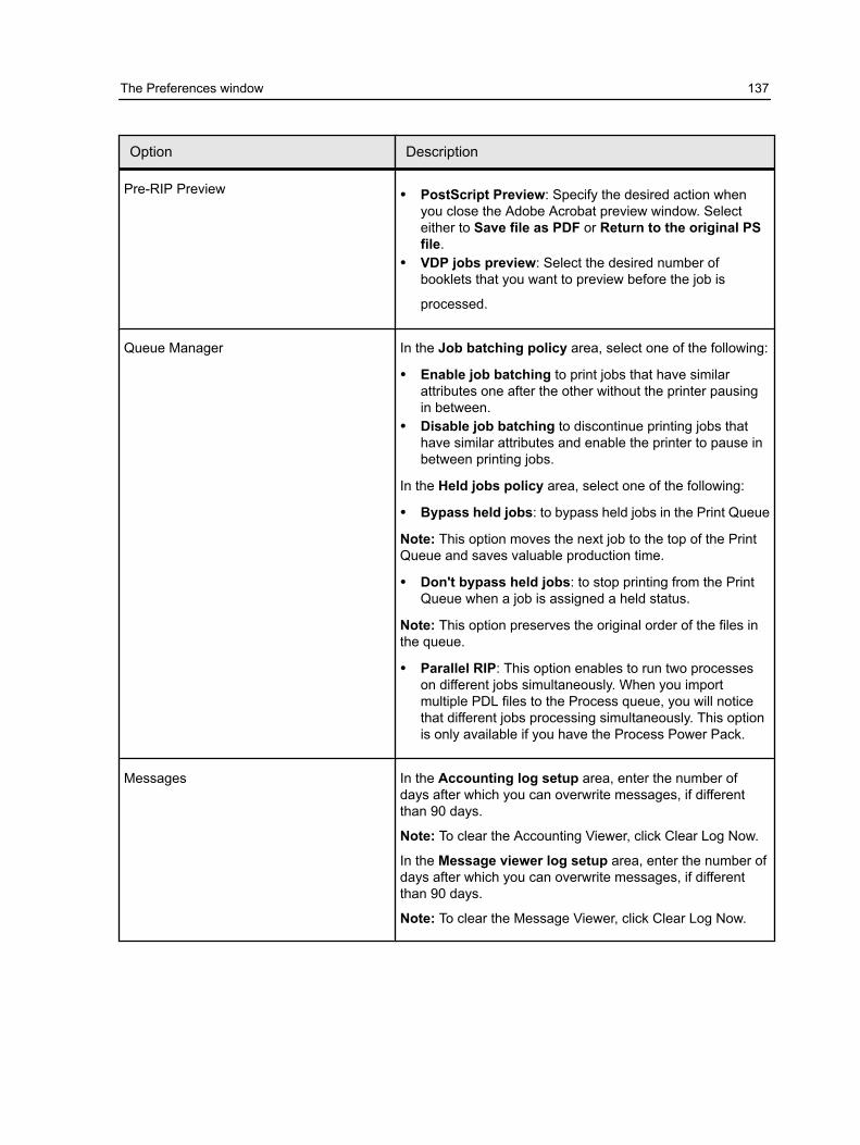
Option Description
Pre-RIP Preview ● PostScript Preview: Specify the desired action whenyou close the Adobe Acrobat preview window. Selecteither to Save file as PDF or Return to the original PSfile.
● VDP jobs preview: Select the desired number ofbooklets that you want to preview before the job is
processed.
Queue Manager In the Job batching policy area, select one of the following:
● Enable job batching to print jobs that have similarattributes one after the other without the printer pausingin between.
● Disable job batching to discontinue printing jobs thathave similar attributes and enable the printer to pause inbetween printing jobs.
In the Held jobs policy area, select one of the following:
● Bypass held jobs: to bypass held jobs in the Print Queue
Note: This option moves the next job to the top of the PrintQueue and saves valuable production time.
● Don't bypass held jobs: to stop printing from the PrintQueue when a job is assigned a held status.
Note: This option preserves the original order of the files inthe queue.
● Parallel RIP: This option enables to run two processeson different jobs simultaneously. When you importmultiple PDL files to the Process queue, you will noticethat different jobs processing simultaneously. This optionis only available if you have the Process Power Pack.
Messages In the Accounting log setup area, enter the number ofdays after which you can overwrite messages, if differentthan 90 days.
Note: To clear the Accounting Viewer, click Clear Log Now.
In the Message viewer log setup area, enter the number ofdays after which you can overwrite messages, if differentthan 90 days.
Note: To clear the Message Viewer, click Clear Log Now.
The Preferences window 137

Option Description
JDF/JMF The Color Controller C-80 receives the JDF job ticket via hotfolders, returns JDF output with job accounting information,and submits JMF (Job Messaging Format) signals with thejob's status.
If the JDF job has a target path specified in the job, JDFoutput is always created. For JDF jobs that do not have aspecified target path, the JDF output is only created if thisoption is selected.
Note: In the HTTP URL box, type the file URL or HTTPURL . This enables you to submit JMF signals with the jobstatus each time the job status of every job in the systemchanges.
General Defaults Here you can configure the general defaults of the system.Select from the following options:
● In the Default Image Size area, select the default pagesize that will be used when the system is unable todetermine the page size of the imported job.
● Select the desired OPI setting to specify how an externalhigh-resolution image is placed in a PostScript file as itgoes to RIP. If you select Enable OPI Support, theSupport Helios Server check box is automaticallyselected. If you do not want Helios server support, clearthis check box.
● Select the Default archive path that is displyed whenyou archive jobs.
● In the Job Title Recognition area, select one of thefollowing options:
❐ Use PostScript Internal name: select this option touse the internal file name as written inside thePostScript fileby the print driver.
❐ Use files name (Use when Printing via LPR): selectthis option to use the job’s given file name. Selectingthis option ensures that the job appears in the queuewith the name last given by the user.
● Cache global VDP elements: In order to manage yourVDP elements, you need to make sure that you select tocache your global VDP elements. Select Always cacheglobal VDP elements check box.
● Offset between jobs: Select this option to offset eachcopy of a job between each job.
See also:Secure printing overview on page 39
138 Chapter 12—Setting up your color server

Setting up a virtual printer
Virtual printersThe Color Controller C-80 provides three default virtual printers(network printers).
Virtual printers are used for automating workflows, which thendefine job streaming. They contain preset workflows that areautomatically applied to all print jobs processed with that virtualprinter. There is no need to reset job settings for each job, thusincreasing printing efficiency.
The three default virtual printers are:
In addition to using the default virtual printers, you can also createa virtual printer, or edit a virtual printer's settings.
Adding and editing a virtual printerThis procedure describes how to add a new virtual printer andthen edit job parameters of the virtual printer.
When you add a new virtual printer, you can specify if it ispublished on the network and if the virtual printer parameters willoverride the PPD parameters. If a job that is sent from the client,or downloaded to a particular virtual printer contains presetparameters from the PPD, these options overwrite the parametersset in the virtual printer for that job. The Printer Default optionsdefined in the PPD file use the default parameters set for thatparticular virtual printer.
1. From the Tools menu, select Resource Center.2. In the Resource list, make sure that Virtual Printers is selected.3. Click .4. In the Name box, type a name for the new printer that you want
to add.5. From the Based on list, select an existing printer with similar
settings.6. The Publish on the network check box is selected by default.
Clear the check box if you do not want to publish the printer onthe network.
Setting up a virtual printer 139

7. Select the Override PPD parameters check box if you wouldlike the virtual printer settings to override the parameters set inthe PPD file.
8. In the Comments box, type any comment regarding the virtualprinter parameters (optional).
9. Click Edit to change the job parameters of your new virtualprinter.
Note: If you don't edit the job parameters, the settings of thenew virtual printer are taken from the printer on which it wasbased.
10.Click OK.
The new printer appears in the virtual printer list.
Removing a virtual printerThe three default virtual printers cannot be deleted.
1. From the Tools menu, select Resource Center.2. In the Resource list, make sure that Virtual Printers is selected.3. From the virtual printer list, select the virtual printer that you
want to delete, and then click .4. Click Yes.
Maintaining your settings
Backing up the configurationYou can back up your configuration to a local hard disk, networkdrive, or to CD or DVD media.
1. From the File menu, select Preferences.
The Preferences window appears.2. In the Preferences window, select Configuration Backup.3. In the Configuration backup area, click Browse.
The Save dialog box appears.4. Locate the desired folder for backup.5. Enter the file name.
Note: It is recommended that you use the current date as partof the file name.
6. Click Save.
140 Chapter 12—Setting up your color server

7. In the Configuration backup area, click Start Backup.After a few moments, the backup complete message appears.
Note: The last path is saved and displayed to the path box. Ifthe backup was made to external media, the displayed path willbe the default: .
Restoring the configurationRequirements:
Make sure that you have previously backed up your configuration.
The configuration file extension is .cnf.
Note: Restore can only be implemented for the same softwareversion.
1. From the File menu, select Preferences.
The Preferences window appears.2. In the Preferences window, select Configuration Backup.3. In the Restore configuration area, click Browse.
The Open dialog box appears.4. Locate the folder in which you backed up the configuration.5. Select the file, and then click Open.6. Click Start Restore.7. Select the categories that you want to restore, and click OK.
All custom tables and sets—for example, new virtual printers— areadded to the system when you restore the configuration.
Restoring the configuration 141

142 Chapter 12—Setting up your color server
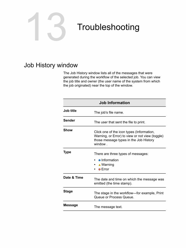
13 Troubleshooting
Job History windowThe Job History window lists all of the messages that weregenerated during the workflow of the selected job. You can viewthe job title and owner (the user name of the system from whichthe job originated) near the top of the window.
Job Information
Job title The job's file name.
Sender The user that sent the file to print.
Show Click one of the icon types (Information,Warning, or Error) to view or not view (toggle)those message types in the Job Historywindow .
Type There are three types of messages:
● Information● Warning● Error
Date & Time The date and time on which the message wasemitted (the time stamp).
Stage The stage in the workflow—for example, PrintQueue or Process Queue.
Message The message text.

Aborting a jobRequirements:
A job is processing or printing.
Right-click the running job in one of the queues, and selectAbort.
The job moves from the queue to the Storage area. The Abortedstatus is assigned to the job, and the next job in the queue startsrunning.
Alerts windowIn the Alerts window you can view system alerts, and alerts for theselected job.
Alert window options
Show Selected Displays the alert for the selected job in thequeues or Storage area.
Show All Displays systems alerts and the alerts for theselected job.
Clear Alerts Clears all of the alerts from the window.
144 Chapter 13—Troubleshooting
Printing system messagesPrint a list of system messages from the Message Viewer window.
1. From the Info menu, select Messages Viewer.2. Filter and sort the message list as desired.
● Click any message type icon —for example, Error—inorder not to list such messages.
● Click a column header to sort the list by that column.3. Click Print List..
The Print window is displayed.4. Set the printing options as desired, and click OK.
The data is printed according to the current filtering and sorting.
Printing system messages 145

146 Chapter 13—Troubleshooting