
Landmark Walkway 66 Gurgaon (7838334455) Landmark Walkway 66
1
PRPRPRPRPRO 66 DieselO 66 DieselO 66 DieselO 66 DieselO 66 Diesel
OPERAOPERAOPERAOPERAOPERATING INSTRTING INSTRTING INSTRTING INSTRTING INSTRUCTIONSUCTIONSUCTIONSUCTIONSUCTIONS
542201029 July 21, 2004

2
Reference Information:
Model No.:
Serial No.:
Engine Serial No.:
Date Purchased:
NOTES:
3
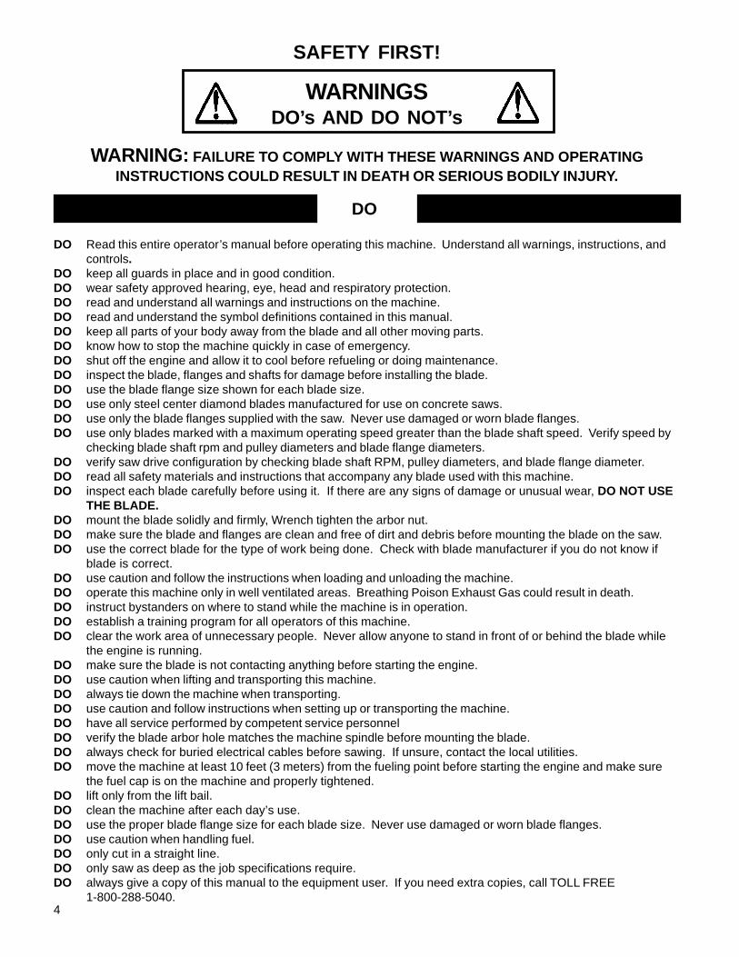
EVERY MACHINE IS THOROUGHLY TESTED BEFORE LEAVING THE FACTORY. EACH MACHINEIS SUPPLIED WITH A COPY OF THIS MANUAL. OPERATORS OF THIS EQUIPMENT MUST READ AND BEFAMILIAR WITH THE SAFETY WARNINGS. FAILURE TO OBEY WARNINGS MAY RESULT IN INJURY ORDEATH. FOLLOW INSTRUCTIONS STRICTLY TO ENSURE LONG SERVICE IN NORMAL OPERATION.
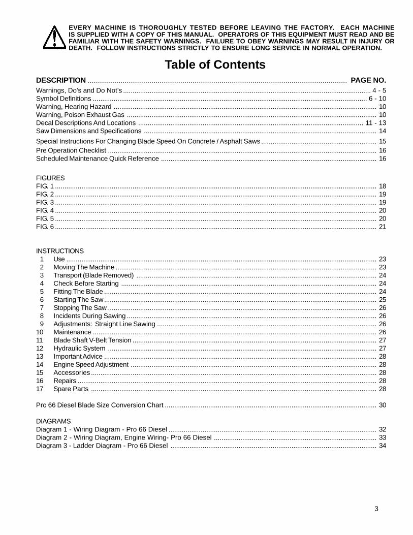
Table of ContentsDESCRIPTION .............................................................................................................................. PAGE NO.Warnings, Do’s and Do Not’s ................................................................................................................................... 4 - 5Symbol Definitions ................................................................................................................................................. 6 - 10Warning, Hearing Hazard ........................................................................................................................................... 10Warning, Poison Exhaust Gas .................................................................................................................................... 10Decal Descriptions And Locations ....................................................................................................................... 11 - 13Saw Dimensions and Specifications ........................................................................................................................... 14
Special Instructions For Changing Blade Speed On Concrete / Asphalt Saws ............................................................. 15Pre Operation Checklist .............................................................................................................................................. 16Scheduled Maintenance Quick Reference .................................................................................................................. 16
FIGURESFIG. 1 .......................................................................................................................................................................... 18FIG. 2 .......................................................................................................................................................................... 19FIG. 3 .......................................................................................................................................................................... 19FIG. 4 .......................................................................................................................................................................... 20FIG. 5 .......................................................................................................................................................................... 20FIG. 6 .......................................................................................................................................................................... 21
INSTRUCTIONS 1 Use .................................................................................................................................................................... 23 2 Moving The Machine .......................................................................................................................................... 23 3 Transport (Blade Removed) ............................................................................................................................... 24 4 Check Before Starting ....................................................................................................................................... 24 5 Fitting The Blade ................................................................................................................................................ 24 6 Starting The Saw................................................................................................................................................ 25 7 Stopping The Saw .............................................................................................................................................. 26 8 Incidents During Sawing .................................................................................................................................... 26 9 Adjustments: Straight Line Sawing .................................................................................................................... 2610 Maintenance ...................................................................................................................................................... 2611 Blade Shaft V-Belt Tension ................................................................................................................................. 2712 Hydraulic System .............................................................................................................................................. 2713 Important Advice ................................................................................................................................................ 2814 Engine Speed Adjustment .................................................................................................................................. 2815 Accessories ....................................................................................................................................................... 2816 Repairs .............................................................................................................................................................. 2817 Spare Parts ....................................................................................................................................................... 28
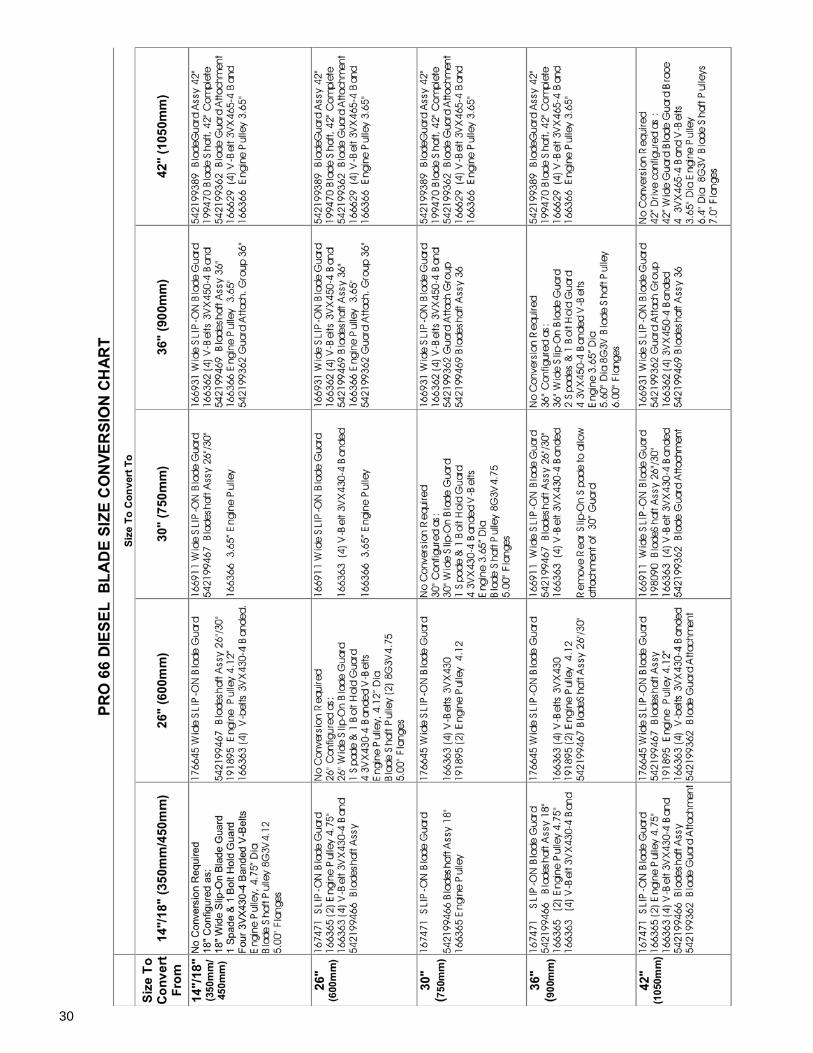
Pro 66 Diesel Blade Size Conversion Chart ................................................................................................................ 30
DIAGRAMSDiagram 1 - Wiring Diagram - Pro 66 Diesel .............................................................................................................. 32Diagram 2 - Wiring Diagram, Engine Wiring- Pro 66 Diesel ...................................................................................... 33Diagram 3 - Ladder Diagram - Pro 66 Diesel ............................................................................................................. 34
4
DO Read this entire operator’s manual before operating this machine. Understand all warnings, instructions, andcontrols.
DO keep all guards in place and in good condition.DO wear safety approved hearing, eye, head and respiratory protection.DO read and understand all warnings and instructions on the machine.DO read and understand the symbol definitions contained in this manual.DO keep all parts of your body away from the blade and all other moving parts.DO know how to stop the machine quickly in case of emergency.DO shut off the engine and allow it to cool before refueling or doing maintenance.DO inspect the blade, flanges and shafts for damage before installing the blade.DO use the blade flange size shown for each blade size.DO use only steel center diamond blades manufactured for use on concrete saws.DO use only the blade flanges supplied with the saw. Never use damaged or worn blade flanges.DO use only blades marked with a maximum operating speed greater than the blade shaft speed. Verify speed by
checking blade shaft rpm and pulley diameters and blade flange diameters.DO verify saw drive configuration by checking blade shaft RPM, pulley diameters, and blade flange diameter.DO read all safety materials and instructions that accompany any blade used with this machine.DO inspect each blade carefully before using it. If there are any signs of damage or unusual wear, DO NOT USE
THE BLADE.DO mount the blade solidly and firmly, Wrench tighten the arbor nut.DO make sure the blade and flanges are clean and free of dirt and debris before mounting the blade on the saw.DO use the correct blade for the type of work being done. Check with blade manufacturer if you do not know if
blade is correct.DO use caution and follow the instructions when loading and unloading the machine.DO operate this machine only in well ventilated areas. Breathing Poison Exhaust Gas could result in death.DO instruct bystanders on where to stand while the machine is in operation.DO establish a training program for all operators of this machine.DO clear the work area of unnecessary people. Never allow anyone to stand in front of or behind the blade while
the engine is running.DO make sure the blade is not contacting anything before starting the engine.DO use caution when lifting and transporting this machine.DO always tie down the machine when transporting.DO use caution and follow instructions when setting up or transporting the machine.DO have all service performed by competent service personnelDO verify the blade arbor hole matches the machine spindle before mounting the blade.DO always check for buried electrical cables before sawing. If unsure, contact the local utilities.DO move the machine at least 10 feet (3 meters) from the fueling point before starting the engine and make sure
the fuel cap is on the machine and properly tightened.DO lift only from the lift bail.DO clean the machine after each day’s use.DO use the proper blade flange size for each blade size. Never use damaged or worn blade flanges.DO use caution when handling fuel.DO only cut in a straight line.DO only saw as deep as the job specifications require.DO always give a copy of this manual to the equipment user. If you need extra copies, call TOLL FREE
1-800-288-5040.
SAFETY FIRST!
WARNINGSDO’s AND DO NOT’s
WARNING: FAILURE TO COMPLY WITH THESE WARNINGS AND OPERATINGINSTRUCTIONS COULD RESULT IN DEATH OR SERIOUS BODILY INJURY.
DO

5
*****************This saw was designed for certain applications only. DO NOT modify this saw or use for any application otherthan for which is it was designed. If you have any questions relative to its application, DO NOT use the saw untilyou have written Electrolux Construction Products and we have advised you.
Electrolux Construction Products North America17400 West 119th Street
Olathe, Kansas 66061USA
DO NOT operate this machine unless you have read and understood this operator’s manual.DO NOT operate this machine without the blade guard, or other protective guards in place.DO NOT stand behind or in front of the blade path while the engine is running.DO NOT leave this machine unattended while the engine is running.DO NOT work on this machine while the engine is running.DO NOT operate this machine when you are tired or fatigued.DO NOT use a wet blade without adequate water supply to the blade.DO NOT exceed maximum blade speed shown for each blade size. Excessive speed could result in blade breakage.DO NOT operate the machine if you are uncertain of how to run the machine.DO NOT use damaged equipment or blades.DO NOT touch or try to stop a moving blade with your hand.DO NOT cock, jam, wedge or twist the blade in a cut.DO NOT transport a cutting machine with the blade mounted on the machine.DO NOT use a blade that has been dropped or damagedDO NOT use carbide tipped blades.DO NOT touch a dry cutting diamond blade immediately after use. These blades require several minutes to cool
after each cut.DO NOT use damaged or worn blade flanges.DO NOT allow other persons to be near the machine when starting, refueling, or when the machine is in operation.DO NOT operate this machine in an enclosed area. Breathing Poison Exhaust Gas could result in death.DO NOT operate this machine in the vicinity of anything that is flammable. Sparks could cause a fire or an
explosion.DO NOT allow blade exposure from the guard to be more than 180 degrees.DO NOT operate this machine with the belt guards or blade guard removed.DO NOT operate this machine unless you are specifically trained to do so.DO NOT use a blade that has been over heated (Core has a bluish color).DO NOT jam material into the blade.DO NOT grind on the side of the blade.DO NOT tow this machine behind a vehicle.DO NOT use the tie down brackets for lifting this machine.DO NOT operate this machine with the any guards or shields removed.DO NOT cut deeper than 1" per pass with a dry blade. Step cut to achieve deeper cuts.DO NOT operate this machine while using drugs or alcohol.DO NOT engage bladeclutch with the engine RPM higher than 1200
SAFETY FIRST!
WARNINGSDO’s AND DO NOT’s
WARNING: FAILURE TO COMPLY WITH THESE WARNINGS AND OPERATINGINSTRUCTIONS COULD RESULT IN DEATH OR SERIOUS BODILY INJURY.
DO NOT
6
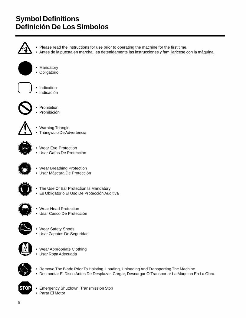
Symbol DefinitionsDefinición De Los Simbolos
• Please read the instructions for use prior to operating the machine for the first time.• Antes de la puesta en marcha, lea detenidamente las instrucciones y familiaricese con la máquina.
• Mandatory• Obligatorio
• Indication• Indicación
• Prohibition• Prohibición
• Warning Triangle• Triángwulo De Advertencia
• Wear Eye Protection• Usar Gafas De Protección
• Wear Breathing Protection• Usar Máscara De Protección
• The Use Of Ear Protection Is Mandatory• Es Obligatorio El Uso De Protección Auditiva
• Wear Head Protection• Usar Casco De Protección
• Wear Safety Shoes• Usar Zapatos De Seguridad
• Wear Appropriate Clothing• Usar Ropa Adecuada
• Remove The Blade Prior To Hoisting, Loading, Unloading And Transporting The Machine.• Desmontar El Disco Antes De Desplazar, Cargar, Descargar O Transportar La Máquina En La Obra.
• Emergency Shutdown, Transmission Stop• Parar El Motor
7
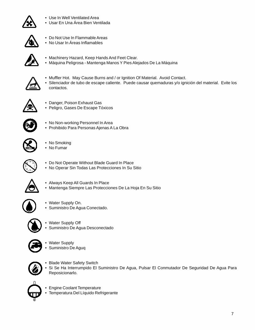
• Use In Well Ventilated Area• Usar En Una Área Bien Ventilada
• Do Not Use In Flammable Areas• No Usar In Áreas Inflamables
• Machinery Hazard, Keep Hands And Feet Clear.• Máquina Peligrosa - Mantenga Manos Y Pies Alejados De La Máquina
• Muffler Hot. May Cause Burns and / or Ignition Of Material. Avoid Contact.• Silenciador de tubo de escape caliente. Puede causar quemaduras y/o ignición del material. Evite los
contactos.
• Danger, Poison Exhaust Gas• Peligro, Gases De Escape Tóxicos
• No Non-working Personnel In Area• Prohibido Para Personas Ajenas A La Obra
• No Smoking• No Fumar
• Do Not Operate Without Blade Guard In Place• No Operar Sin Todas Las Protecciones In Su Sitio
• Always Keep All Guards In Place• Mantenga Siempre Las Protecciones De La Hoja En Su Sitio
• Water Supply On.• Suministro De Agua Conectado.
• Water Supply Off• Suministro De Agua Desconectado
• Water Supply• Suministro De Aguq
• Blade Water Safety Switch• Si Se Ha Interrumpido El Suministro De Agua, Pulsar El Conmutador De Seguridad De Agua Para
Reposicionarlo.
• Engine Coolant Temperature• Temperatura Del Líquido Refrigerante
8
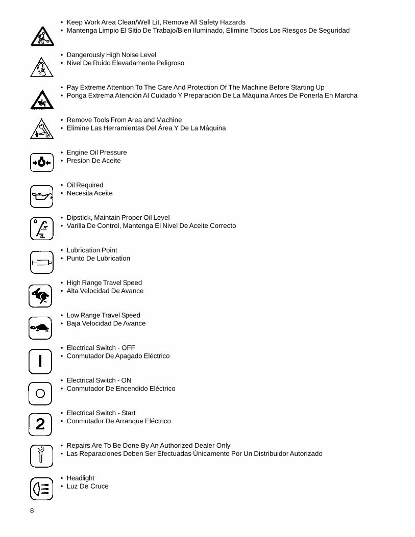
• Keep Work Area Clean/Well Lit, Remove All Safety Hazards• Mantenga Limpio El Sitio De Trabajo/Bien Iluminado, Elimine Todos Los Riesgos De Seguridad
• Dangerously High Noise Level• Nivel De Ruido Elevadamente Peligroso
• Pay Extreme Attention To The Care And Protection Of The Machine Before Starting Up• Ponga Extrema Atención Al Cuidado Y Preparación De La Máquina Antes De Ponerla En Marcha
• Remove Tools From Area and Machine• Elimine Las Herramientas Del Área Y De La Máquina
• Engine Oil Pressure• Presion De Aceite
• Oil Required• Necesita Aceite
• Dipstick, Maintain Proper Oil Level• Varilla De Control, Mantenga El Nivel De Aceite Correcto
• Lubrication Point• Punto De Lubrication
• High Range Travel Speed• Alta Velocidad De Avance
• Low Range Travel Speed• Baja Velocidad De Avance
• Electrical Switch - OFF• Conmutador De Apagado Eléctrico
• Electrical Switch - ON• Conmutador De Encendido Eléctrico
• Electrical Switch - Start• Conmutador De Arranque Eléctrico
• Repairs Are To Be Done By An Authorized Dealer Only• Las Reparaciones Deben Ser Efectuadas Únicamente Por Un Distribuidor Autorizado
• Headlight• Luz De Cruce
9
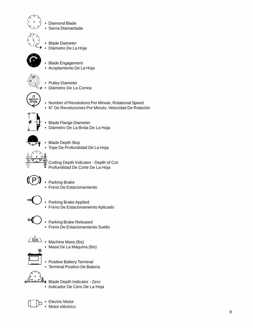
• Diamond Blade• Sierra Diamantada
• Blade Diameter• Diámetro De La Hoja
• Blade Engagement• Acoplamiento De La Hoja
• Pulley Diameter• Diámetro De La Correa
• Number of Revolutions Per Minute, Rotational Speed• N° De Revoluciones Por Minuto, Velocidad De Rotación
• Blade Flange Diameter• Diámetro De La Brida De La Hoja
• Blade Depth Stop• Tope De Profundidad De La Hoja
• Cutting Depth Indicator - Depth of Cut• Profundidad De Corte De La Hoja
• Parking Brake• Freno De Estacionamiento
• Parking Brake Applied• Freno De Estacionamiento Aplicado
• Parking Brake Released• Freno De Estacionamiento Suelto
• Machine Mass (lbs)• Masa De La Máquina (lbs)
• Positive Battery Terminal• Terminal Positivo De Batería
• Blade Depth Indicator - Zero• Indicador De Cero De La Hoja
• Electric Motor• Motor eléctrico
10
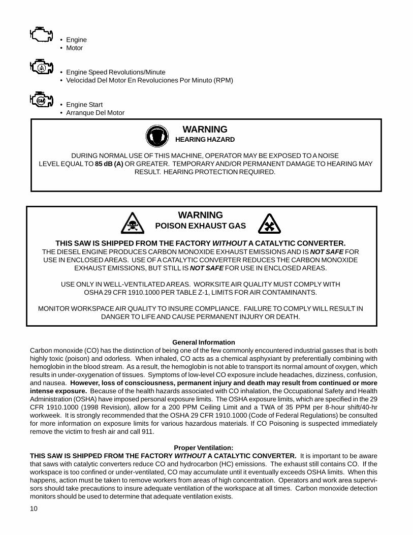
• Engine• Motor
• Engine Speed Revolutions/Minute• Velocidad Del Motor En Revoluciones Por Minuto (RPM)
• Engine Start• Arranque Del Motor
General InformationCarbon monoxide (CO) has the distinction of being one of the few commonly encountered industrial gasses that is bothhighly toxic (poison) and odorless. When inhaled, CO acts as a chemical asphyxiant by preferentially combining withhemoglobin in the blood stream. As a result, the hemoglobin is not able to transport its normal amount of oxygen, whichresults in under-oxygenation of tissues. Symptoms of low-level CO exposure include headaches, dizziness, confusion,and nausea. However, loss of consciousness, permanent injury and death may result from continued or moreintense exposure. Because of the health hazards associated with CO inhalation, the Occupational Safety and HealthAdministration (OSHA) have imposed personal exposure limits. The OSHA exposure limits, which are specified in the 29CFR 1910.1000 (1998 Revision), allow for a 200 PPM Ceiling Limit and a TWA of 35 PPM per 8-hour shift/40-hrworkweek. It is strongly recommended that the OSHA 29 CFR 1910.1000 (Code of Federal Regulations) be consultedfor more information on exposure limits for various hazardous materials. If CO Poisoning is suspected immediatelyremove the victim to fresh air and call 911.
Proper Ventilation:THIS SAW IS SHIPPED FROM THE FACTORY WITHOUT A CATALYTIC CONVERTER. It is important to be awarethat saws with catalytic converters reduce CO and hydrocarbon (HC) emissions. The exhaust still contains CO. If theworkspace is too confined or under-ventilated, CO may accumulate until it eventually exceeds OSHA limits. When thishappens, action must be taken to remove workers from areas of high concentration. Operators and work area supervi-sors should take precautions to insure adequate ventilation of the workspace at all times. Carbon monoxide detectionmonitors should be used to determine that adequate ventilation exists.
WARNINGHEARING HAZARD
DURING NORMAL USE OF THIS MACHINE, OPERATOR MAY BE EXPOSED TO A NOISE LEVEL EQUAL TO 85 dB (A) OR GREATER. TEMPORARY AND/OR PERMANENT DAMAGE TO HEARING MAY
RESULT. HEARING PROTECTION REQUIRED.
WARNINGPOISON EXHAUST GAS
THIS SAW IS SHIPPED FROM THE FACTORY WITHOUT A CATALYTIC CONVERTER.THE DIESEL ENGINE PRODUCES CARBON MONOXIDE EXHAUST EMISSIONS AND IS NOT SAFE FORUSE IN ENCLOSED AREAS. USE OF A CATALYTIC CONVERTER REDUCES THE CARBON MONOXIDE
EXHAUST EMISSIONS, BUT STILL IS NOT SAFE FOR USE IN ENCLOSED AREAS.
USE ONLY IN WELL-VENTILATED AREAS. WORKSITE AIR QUALITY MUST COMPLY WITHOSHA 29 CFR 1910.1000 PER TABLE Z-1, LIMITS FOR AIR CONTAMINANTS.
MONITOR WORKSPACE AIR QUALITY TO INSURE COMPLIANCE. FAILURE TO COMPLY WILL RESULT INDANGER TO LIFE AND CAUSE PERMANENT INJURY OR DEATH.
11
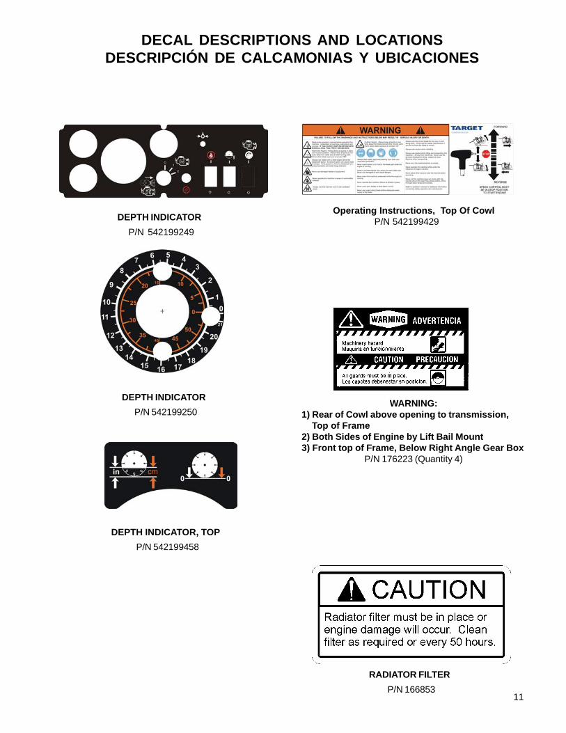
DECAL DESCRIPTIONS AND LOCATIONSDESCRIPCIÓN DE CALCAMONIAS Y UBICACIONES
RADIATOR FILTER
P/N 166853
DEPTH INDICATOR
P/N 542199249
WARNING:1) Rear of Cowl above opening to transmission, Top of Frame2) Both Sides of Engine by Lift Bail Mount3) Front top of Frame, Below Right Angle Gear Box
P/N 176223 (Quantity 4)
DEPTH INDICATOR
P/N 542199250
DEPTH INDICATOR, TOP
P/N 542199458
Operating Instructions, Top Of Cowl P/N 542199429
12
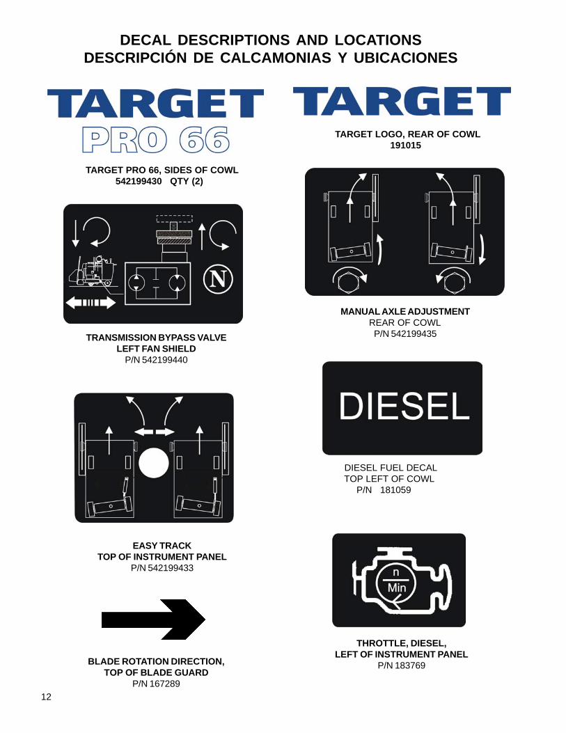
DECAL DESCRIPTIONS AND LOCATIONSDESCRIPCIÓN DE CALCAMONIAS Y UBICACIONES
TRANSMISSION BYPASS VALVELEFT FAN SHIELD
P/N 542199440
BLADE ROTATION DIRECTION,TOP OF BLADE GUARD
P/N 167289
THROTTLE, DIESEL,LEFT OF INSTRUMENT PANEL
P/N 183769
TARGET LOGO, REAR OF COWL 191015
TARGET PRO 66, SIDES OF COWL 542199430 QTY (2)
MANUAL AXLE ADJUSTMENT REAR OF COWL
P/N 542199435
EASY TRACKTOP OF INSTRUMENT PANEL
P/N 542199433
DIESEL FUEL DECAL TOP LEFT OF COWL P/N 181059

13
DECAL DESCRIPTIONS AND LOCATIONSDESCRIPCIÓN DE CALCAMONIAS Y UBICACIONES
MUFFLER HOT,Front Side of Muffler Brace
Right Side Top of Fan ShieldP/N 169065 (Quantity (2))
BLADE GUARD WARNING,TOP OF BLADE GUARD
P/N 046128
BLADE GUARD WARNING,TOP OF BLADE GUARD
P/N 167298
PATENTSP/N 180427
BLADESPEED CHART TOP OF INSTRUMENT PANEL P/N 542199434
14
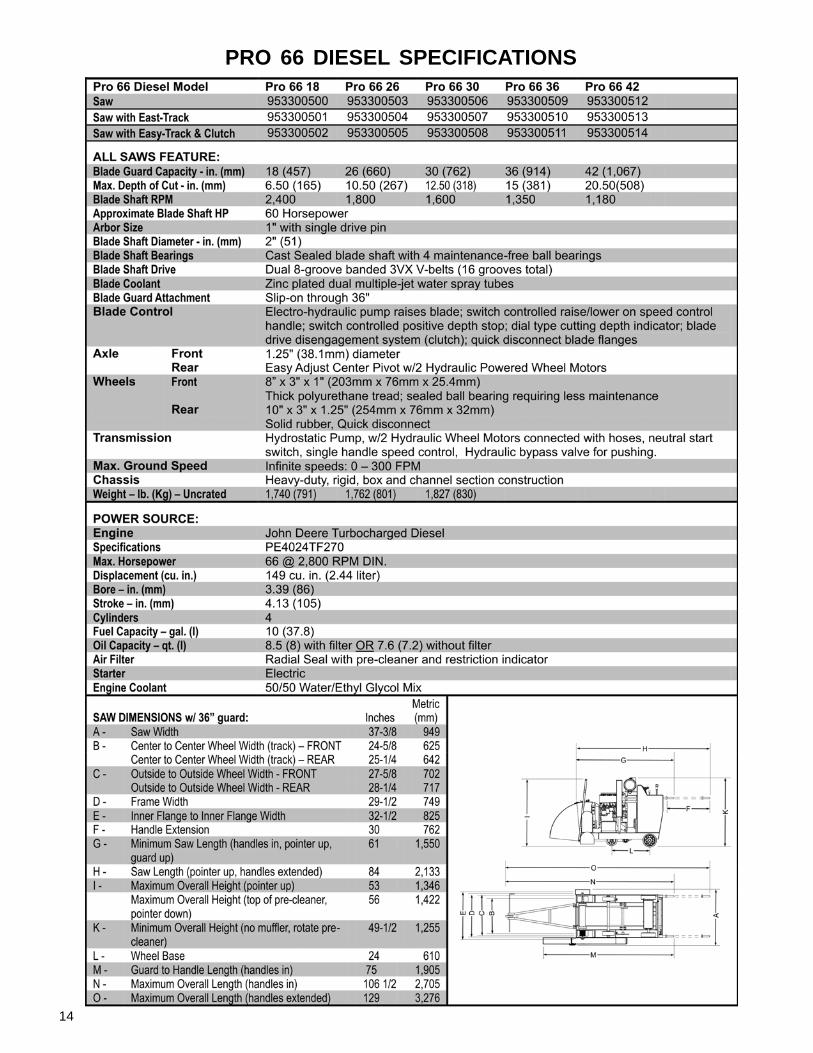
PRO 66 DIESEL SPECIFICATIONS

15
SPECIAL INSTRUCTIONS FOR CHANGING BLADE SPEEDON CONCRETE / ASPHALT SAWS
WARNING: Do not exceed blade shaft speed shown for each blade size. Excessive bladespeed could result in blade breakage and serious personal injury.
NOTE: As shown on the chart, some blade guards accept more than one size blade.
16
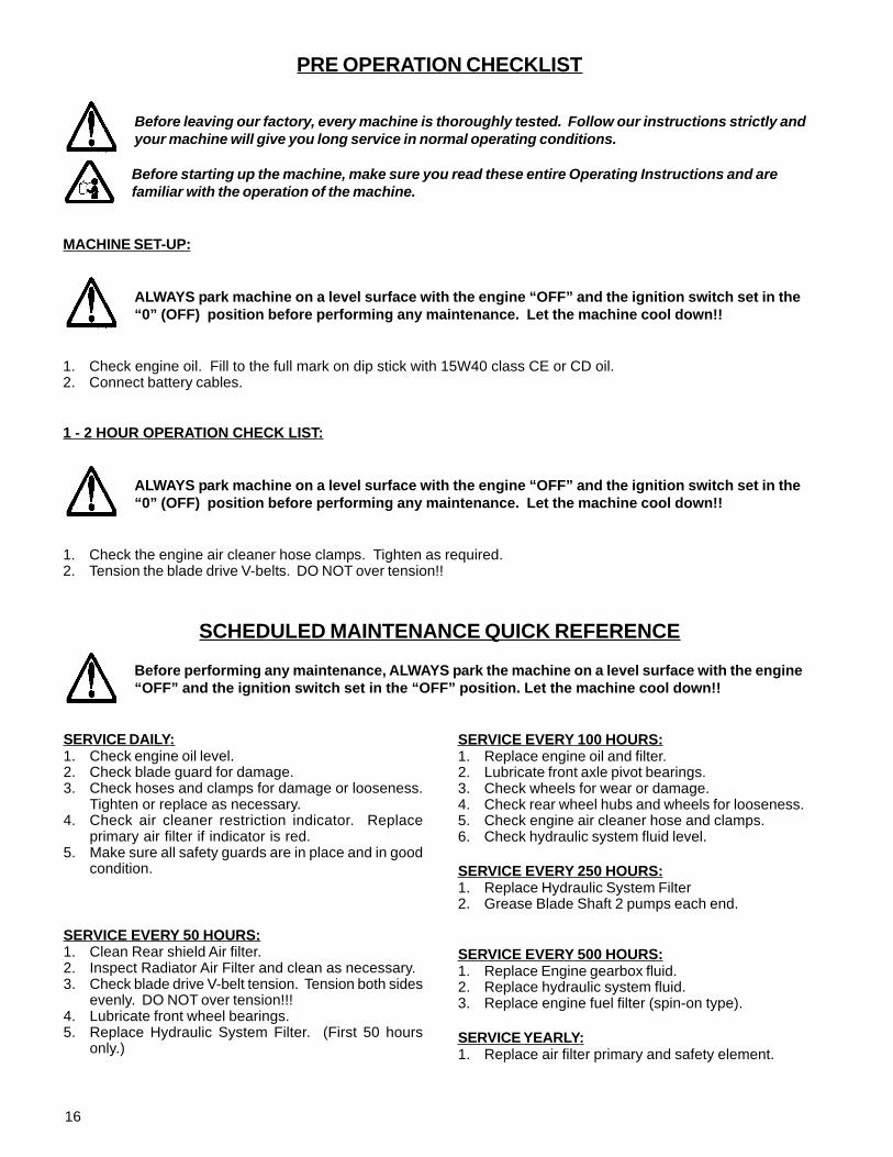
SERVICE DAILY:1. Check engine oil level.2. Check blade guard for damage.3. Check hoses and clamps for damage or looseness.
Tighten or replace as necessary.4. Check air cleaner restriction indicator. Replace
primary air filter if indicator is red.5. Make sure all safety guards are in place and in good
condition.
SERVICE EVERY 50 HOURS:1. Clean Rear shield Air filter.2. Inspect Radiator Air Filter and clean as necessary.3. Check blade drive V-belt tension. Tension both sides
evenly. DO NOT over tension!!!4. Lubricate front wheel bearings.5. Replace Hydraulic System Filter. (First 50 hours
only.)
SERVICE EVERY 100 HOURS:1. Replace engine oil and filter.2. Lubricate front axle pivot bearings.3. Check wheels for wear or damage.4. Check rear wheel hubs and wheels for looseness.5. Check engine air cleaner hose and clamps.6. Check hydraulic system fluid level.
SERVICE EVERY 250 HOURS:1. Replace Hydraulic System Filter2. Grease Blade Shaft 2 pumps each end.
SERVICE EVERY 500 HOURS:1. Replace Engine gearbox fluid.2. Replace hydraulic system fluid.3. Replace engine fuel filter (spin-on type).
SERVICE YEARLY:1. Replace air filter primary and safety element.
PRE OPERATION CHECKLIST
Before leaving our factory, every machine is thoroughly tested. Follow our instructions strictly andyour machine will give you long service in normal operating conditions.
Before starting up the machine, make sure you read these entire Operating Instructions and arefamiliar with the operation of the machine.
MACHINE SET-UP:
ALWAYS park machine on a level surface with the engine “OFF” and the ignition switch set in the“0” (OFF) position before performing any maintenance. Let the machine cool down!!
1. Check engine oil. Fill to the full mark on dip stick with 15W40 class CE or CD oil.2. Connect battery cables.
1 - 2 HOUR OPERATION CHECK LIST:
ALWAYS park machine on a level surface with the engine “OFF” and the ignition switch set in the“0” (OFF) position before performing any maintenance. Let the machine cool down!!
1. Check the engine air cleaner hose clamps. Tighten as required.2. Tension the blade drive V-belts. DO NOT over tension!!
SCHEDULED MAINTENANCE QUICK REFERENCE
Before performing any maintenance, ALWAYS park the machine on a level surface with the engine“OFF” and the ignition switch set in the “OFF” position. Let the machine cool down!!
17
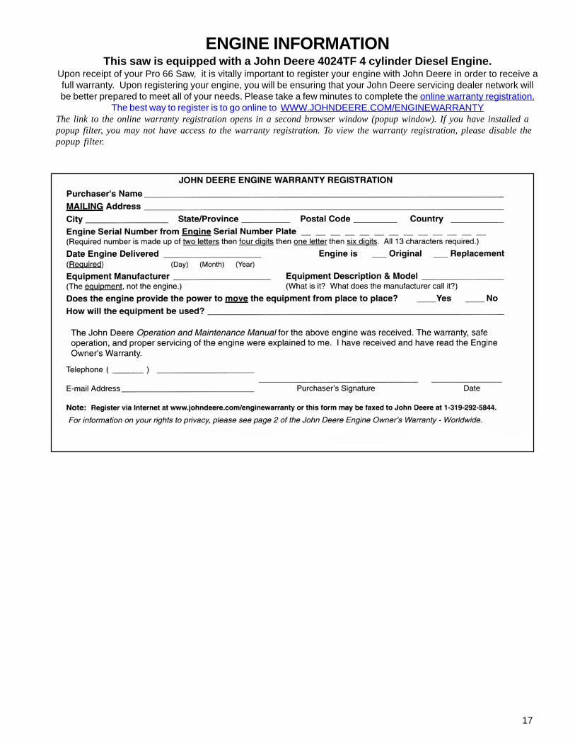
ENGINE INFORMATIONThis saw is equipped with a John Deere 4024TF 4 cylinder Diesel Engine.
Upon receipt of your Pro 66 Saw, it is vitally important to register your engine with John Deere in order to receive afull warranty. Upon registering your engine, you will be ensuring that your John Deere servicing dealer network willbe better prepared to meet all of your needs. Please take a few minutes to complete the online warranty registration.
The best way to register is to go online to WWW.JOHNDEERE.COM/ENGINEWARRANTYThe link to the online warranty registration opens in a second browser window (popup window). If you have installed apopup filter, you may not have access to the warranty registration. To view the warranty registration, please disable thepopup filter.
18
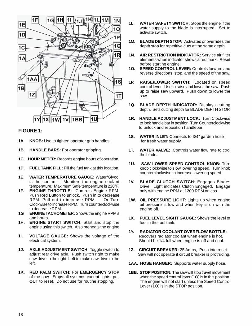
FIGURE 1:
1A. KNOB: Use to tighten operator grip handles.
1B. HANDLE BARS: For operator gripping.
1C. HOUR METER: Records engine hours of operation.
1D. FUEL TANK FILL: Fill the fuel tank at this location.
1E. WATER TEMPERATURE GAUGE: Water/Glycolis the coolant . Monitors the engine coolanttemperature. Maximum Safe temperature is 220°F.
1F. ENGINE THROTTLE: Controls Engine RPM.Push Red Button to unlock. Push in to decreaseRPM. Pull out to increase RPM. Or TurnClockwise to increase RPM. Turn counterclockwiseto decrease RPM.
1G. ENGINE TACHOMETER: Shows the engine RPM’sand hours.
1H. ENGINE START SWITCH: Start and stop theengine using this switch. Also preheats the engine
1I. VOLTAGE GAUGE: Shows the voltage of theelectrical system.
1J. AXLE ADJUSTMENT SWITCH: Toggle switch toadjust rear drive axle. Push switch right to makesaw drive to the right. Left to make saw drive to theleft.
1K. RED PALM SWITCH: For EMERGENCY STOPof the saw. Stops all systems except lights, pullOUT to reset. Do not use for routine stopping.
1L. WATER SAFETY SWITCH: Stops the engine if thewater supply to the blade is interrupted. Set toactivate switch.
1M. BLADE DEPTH STOP: Activates or overrides thedepth stop for repetitive cuts at the same depth.
1N. AIR RESTRICTION INDICATOR: Service air filterelements when indicator shows a red mark. Resetbefore starting engine.
1O. SPEED CONTROL LEVER: Controls forward andreverse directions, stop, and the speed of the saw.
1P. RAISE/LOWER SWITCH: Located on speedcontrol lever. Use to raise and lower the saw. Pushup to raise saw upward. Push down to lower thesaw.
1Q. BLADE DEPTH INDICATOR: Displays cuttingdepth. Sets cutting depth for BLADE DEPTH STOP.
1R. HANDLE ADJUSTMENT LOCK: Turn Clockwiseto lock handle bar in position. Turn Counterclockwise
to unlock and reposition handlebar.
1S. WATER INLET: Connects to 3/4” garden hose for fresh water supply.
1T. WATER VALVE: Controls water flow rate to coolthe blade.
1U. SAW LOWER SPEED CONTROL KNOB: Turnknob clockwise to slow lowering speed. Turn knobcounterclockwise to increase lowering speed.
1V. BLADE CLUTCH SWITCH: Engages BladesDrive. Light indicates Clutch Engaged. Engageonly with engine RPM at 1200 RPM or less
1W. OIL PRESSURE LIGHT: Lights up when engineoil pressure is low and when key is on with theengine off.
1X. FUEL LEVEL SIGHT GAUGE: Shows the level offuel in the fuel tank.
1Y. RADIATOR COOLANT OVERFLOW BOTTLE: Recovers radiator coolant when engine is hot. Should be 1/4 full when engine is off and cool.
1Z. CIRCUIT BREAKER: 25 Amps, Push into reset. Saw will not operate if circuit breaker is protruding.
1AA. HOSE HANGER: Supports water supply hose.
1BB. STOP POSITION: The saw will stop travel movementwhen the speed control lever (1O) is in this position.The engine will not start unless the Speed ControlLever (1O) is in the STOP position.
19
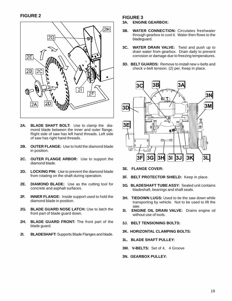
FIGURE 2
2A. BLADE SHAFT BOLT: Use to clamp the dia-mond blade between the inner and outer flange.Right side of saw has left hand threads. Left sideof saw has right hand threads.
2B. OUTER FLANGE: Use to hold the diamond bladein position.
2C. OUTER FLANGE ARBOR: Use to support thediamond blade.
2D. LOCKING PIN: Use to prevent the diamond bladefrom rotating on the shaft during operation.
2E. DIAMOND BLADE: Use as the cutting tool forconcrete and asphalt surfaces.
2F. INNER FLANGE: Inside support used to hold thediamond blade in position.
2G. BLADE GUARD NOSE LATCH: Use to latch thefront part of blade guard down.
2H. BLADE GUARD FRONT: The front part of theblade guard.
2I. BLADESHAFT: Supports Blade Flanges and blade.
FIGURE 33A. ENGINE GEARBOX:
3B. WATER CONNECTION: Circulates freshwaterthrough gearbox to cool it. Water then flows to thebladeguard.
3C. WATER DRAIN VALVE: Twist and push up todrain water from gearbox. Drain daily to preventcorrosion or damage due to freezing temperatures.
3D. BELT GUARDS: Remove to install new v-belts andcheck v-belt tension. (2) per, Keep in place.
3E. FLANGE COVER:
3F. BELT PROTECTOR SHIELD: Keep in place.
3G. BLADESHAFT TUBE ASSY: Sealed unit containsbladeshaft, bearings and shaft seals.
3H. TIEDOWN LUGS: Used to tie the saw down whiletransporting by vehicle. Not to be used to lift thesaw.
3I. ENGINE OIL DRAIN VALVE: Drains engine oilwithout use of tools.
3J. BELT TENSIONING BOLTS:
3K. HORIZONTAL CLAMPING BOLTS:
3L. BLADE SHAFT PULLEY:
3M. V-BELTS: Set of 4, 4 Groove
3N. GEARBOX PULLEY:
20
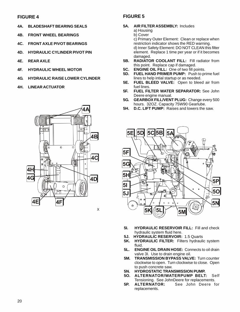
FIGURE 5
5A. AIR FILTER ASSEMBLY: Includesa) Housingb) Coverc) Primary Outer Element: Clean or replace whenrestriction indicator shows the RED warning.d) Inner Safety Element: DO NOT CLEAN this filterelement. Replace 1 time per year or if it becomesdamaged.
5B. RADIATOR COOLANT FILL: Fill radiator fromthis point. Replace cap if damaged.
5C. ENGINE OIL FILL: One of two fill points.5D. FUEL HAND PRIMER PUMP: Push to prime fuel
lines to help intial startup or as needed.5E. FUEL BLEED VALVE: Open to bleed air from
fuel lines.5F. FUEL FILTER WATER SEPARATOR: See John
Deere engine manual.5G. GEARBOX FILL/VENT PLUG: Change every 500
hours. 32OZ. Capacity 75W90 Gearlube.5H. D.C. LIFT PUMP: Raises and lowers the saw.
FIGURE 4
4A. BLADESHAFT BEARING SEALS
4B. FRONT WHEEL BEARINGS
4C. FRONT AXLE PIVOT BEARINGS
4D. HYDRAULIC CYLINDER PIVOT PIN
4E. REAR AXLE
4F. HYDRAULIC WHEEL MOTOR
4G. HYDRAULIC RAISE LOWER CYLINDER
4H. LINEAR ACTUATOR
5I. HYDRAULIC RESERVOIR FILL: Fill and checkhydraulic system fluid here.
5J. HYDRAULIC RESERVOIR: 1.5 Quarts5K. HYDRAULIC FILTER: Filters hydraulic system
fluid.5L. ENGINE OIL DRAIN HOSE: Connects to oil drain
valve 3I. Use to drain engine oil.5M. TRANSMISSION BYPASS VALVE: Turn counter
clockwise to open. Turn clockwise to close. Opento push concrete saw.
5N. HYDROSTATIC TRANSMISSION PUMP.5O. ALTERNATOR/WATERPUMP BELT: Self
Tensioning. See JohnDeere for replacements.5P. ALTERNATOR: See John Deere for
replacements.
21
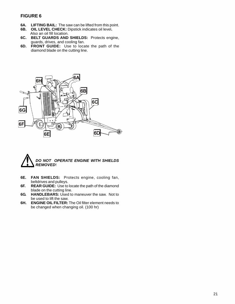
FIGURE 6
6A. LIFTING BAIL: The saw can be lifted from this point.6B. OIL LEVEL CHECK: Dipstick indicates oil level. Also an oil fill location.6C. BELT GUARDS AND SHIELDS: Protects engine,
guards, drives, and cooling fan.6D. FRONT GUIDE: Use to locate the path of the
diamond blade on the cutting line.
DO NOT OPERATE ENGINE WITH SHIELDSREMOVED!
6E. FAN SHIELDS: Protects engine, cooling fan,beltdrives and pulleys.
6F. REAR GUIDE: Use to locate the path of the diamondblade on the cutting line.
6G. HANDLEBARS: Used to maneuver the saw. Not tobe used to lift the saw.
6H. ENGINE OIL FILTER: The Oil filter element needs tobe changed when changing oil. (100 hr)

22
NOTES
23
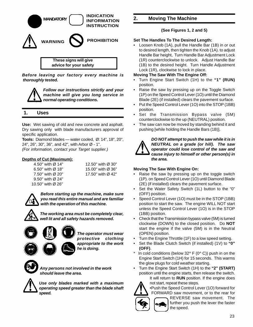
MANDATORYINDICATIONINFORMATIONINSTRUCTION
WARNING PROHIBITION
These signs will giveadvice for your safety
Before leaving our factory every machine is thoroughly tested.
Follow our instructions strictly and yourmachine will give you long service innormal operating conditions.
1. Uses
Use: Wet sawing of old and new concrete and asphalt.Dry sawing only with blade manufacturers approval ofspecific application.Tools: Diamond blades — water cooled, Ø: 14", 18", 20",24", 26", 30", 36", and 42", with Arbor Ø - 1".(For information, contact your Target supplier.)
Depths of Cut (Maximum): 4.50" with Ø 14" 12.50" with Ø 30" 6.50" with Ø 18" 15.00" with Ø 36" 7.50" with Ø 20" 17.50" with Ø 42" 9.50" with Ø 24"10.50" with Ø 26"
Before starting up the machine, make sureyou read this entire manual and are familiarwith the operation of this machine.
The working area must be completely clear,well lit and all safety hazards removed.
The operator must wearprotective clothingappropriate to the workhe is doing.
Any persons not involved in the workshould leave the area.
Use only blades marked with a maximumoperating speed greater than the blade shaftspeed.
2. Moving The Machine
(See Figures 1, 2 and 5)
Set The Handles To The Desired Length:• Loosen Knob (1A), pull the Handle Bar (1B) in or out
to desired length, then tighten the Knob (1A). to adjustHandle Bar height, Turn Handle Bar Adjustment Lock(1R) counterclockwise to unlock. Adjust Handle Bar(1B) to the desired height. Turn Handle AdjustmentLock (1R), clockwise to lock in place.
Moving The Saw With The Engine Off:• Turn Engine Start Switch (1H) to the “1” (RUN)
position.• Raise the saw by pressing up on the Toggle Switch
(1P) on the Speed Control Lever (1O) until the DiamondBlade (2E) (if installed) clears the pavement surface.
• Put the Speed Control Lever (1O) into the STOP (1BB)position.
• Set the Transmission Bypass valve (5M)counterclockwise to the up (NEUTRAL) position.
• The saw can now be moved by standing behind it andpushing [while holding the Handle Bars (1B)].
DO NOT attempt to push the saw while it is inNEUTRAL on a grade (or hill). The sawoperator could lose control of the saw andcause injury to himself or other person(s) inthe area.
Moving The Saw With Engine On:• Raise the saw by pressing up on the toggle switch
(1P). on Speed Control Lever (1O) until Diamond Blade(2E) (if installed) clears the pavement surface.
• Set the Water Safety Switch (1L) button to the “0”(OFF) position.
• Speed Control Lever (1O) must be in the STOP (1BB)position to start the saw. The engine WILL NOT startunless the Speed Control Lever (1O) is in the STOP(1BB) position.
• Check that the Transmission bypass valve (5M) is turnedclockwise (DOWN) to the closed position. Do NOTstart the engine if the valve (5M) is in the Neutral(OPEN) position.
• Turn the Engine Throttle (1F) to a low speed setting.• Set the Blade Clutch Switch (if installed) (1V) to “0”
(OFF).* In cold conditions (below 32^ F (0^ C)) push in on the
Engine Start Switch (1H) for 15 seconds. This warmsthe glow plugs for cold weather starting.
• Turn the Engine Start Switch (1H) to the “2” (START)position until the engine starts, then release the switch.
It will return to RUN position. If the engine doesnot start, repeat these steps.•Push the Speed Control Lever (1O) forward forFORWARD saw movement, or to the rear for
REVERSE saw movement. Thefurther you push the lever the fasterthe speed.
24
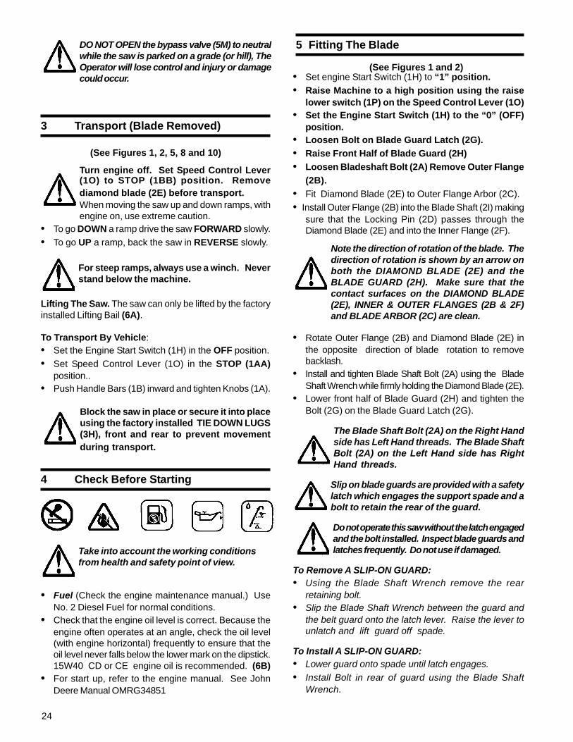
DO NOT OPEN the bypass valve (5M) to neutralwhile the saw is parked on a grade (or hill), TheOperator will lose control and injury or damagecould occur.
3 Transport (Blade Removed)
(See Figures 1, 2, 5, 8 and 10)
Turn engine off. Set Speed Control Lever(1O) to STOP (1BB) position. Removediamond blade (2E) before transport.When moving the saw up and down ramps, withengine on, use extreme caution.
• To go DOWN a ramp drive the saw FORWARD slowly.• To go UP a ramp, back the saw in REVERSE slowly.
For steep ramps, always use a winch. Neverstand below the machine.
Lifting The Saw. The saw can only be lifted by the factoryinstalled Lifting Bail (6A).
To Transport By Vehicle:• Set the Engine Start Switch (1H) in the OFF position.• Set Speed Control Lever (1O) in the STOP (1AA)
position..• Push Handle Bars (1B) inward and tighten Knobs (1A).
Block the saw in place or secure it into placeusing the factory installed TIE DOWN LUGS(3H), front and rear to prevent movementduring transport.
4 Check Before Starting
Take into account the working conditionsfrom health and safety point of view.
• Fuel (Check the engine maintenance manual.) UseNo. 2 Diesel Fuel for normal conditions.
• Check that the engine oil level is correct. Because theengine often operates at an angle, check the oil level(with engine horizontal) frequently to ensure that theoil level never falls below the lower mark on the dipstick.15W40 CD or CE engine oil is recommended. (6B)
• For start up, refer to the engine manual. See JohnDeere Manual OMRG34851
5 Fitting The Blade
(See Figures 1 and 2)• Set engine Start Switch (1H) to “1” position.• Raise Machine to a high position using the raise
lower switch (1P) on the Speed Control Lever (1O)• Set the Engine Start Switch (1H) to the “0” (OFF)
position.• Loosen Bolt on Blade Guard Latch (2G).• Raise Front Half of Blade Guard (2H)• Loosen Bladeshaft Bolt (2A) Remove Outer Flange
(2B).• Fit Diamond Blade (2E) to Outer Flange Arbor (2C).• Install Outer Flange (2B) into the Blade Shaft (2I) making
sure that the Locking Pin (2D) passes through theDiamond Blade (2E) and into the Inner Flange (2F).
Note the direction of rotation of the blade. Thedirection of rotation is shown by an arrow onboth the DIAMOND BLADE (2E) and theBLADE GUARD (2H). Make sure that thecontact surfaces on the DIAMOND BLADE(2E), INNER & OUTER FLANGES (2B & 2F)and BLADE ARBOR (2C) are clean.
• Rotate Outer Flange (2B) and Diamond Blade (2E) inthe opposite direction of blade rotation to removebacklash.
• Install and tighten Blade Shaft Bolt (2A) using the BladeShaft Wrench while firmly holding the Diamond Blade (2E).
• Lower front half of Blade Guard (2H) and tighten theBolt (2G) on the Blade Guard Latch (2G).
The Blade Shaft Bolt (2A) on the Right Handside has Left Hand threads. The Blade ShaftBolt (2A) on the Left Hand side has RightHand threads.
Slip on blade guards are provided with a safetylatch which engages the support spade and abolt to retain the rear of the guard.
Do not operate this saw without the latch engagedand the bolt installed. Inspect blade guards andlatches frequently. Do not use if damaged.
To Remove A SLIP-ON GUARD:• Using the Blade Shaft Wrench remove the rear
retaining bolt.• Slip the Blade Shaft Wrench between the guard and
the belt guard onto the latch lever. Raise the lever tounlatch and lift guard off spade.
To Install A SLIP-ON GUARD:• Lower guard onto spade until latch engages.• Install Bolt in rear of guard using the Blade Shaft
Wrench.
25
6 Starting The Saw
(See Figures 1, 2 and 5)
Always pay extreme care and attention to thepreparation of the machine before starting.
Remove all wrenches and tools from thefloor and the machine.
Always keep blade guard, belt guards andfan guards in place.
• Follow all operating instructions and warnings in thismanual and on the machine.
• Close the Water Valve (1T).• Mark the surface to be cut by drawing a line where
the cut is to be made.• Pull out Handle Bars (1B) to desired length and tighten
Knobs (1A).• Lower the Front Guide (6D) and align the Front Guide
(6D), Rear Guide (6F) and Diamond Blade (2E) withthe line on the surface.
• To start the saw when no water pressure is present,set the Water Safety Switch (1L) to “0” (OFF).
• Set Speed Control Lever (1O) to the STOP (1BB)position. Saw will not start unless the Speed ControlLever (1O) is in the STOP (1BB) position. Check tobe certain the Transmission Bypass Valve (5M) isclosed in the down position.
• Set the Blade Clutch Switch (1T) to “0” (OFF) (ifequipped).
• Start the engine using the Engine Start Switch (1H).Follow the procedure in the engine manual.
In Cold conditions, pre-heat the engine glow plugs byhold in the Engine Start Switch (1H) for 15 seconds.
• Let the engine warm up for several minutes with EngineThrottle (1F) at the low speed setting.
• When ready open the Water Valve (5A, 1Z).• Set Water Safety Switch (1L) to “1”(ON).
Test for adequate water supply. (2.5 - 5.0 GPM)(10 - 20 Liters per Min.) Low water flow willcause damage to diamond blades.
• Pull Throttle (1F) out to set engine RPM at 3000.
See chart for the appropriate blade shaft and enginespeeds for specific blade sizes.
• Move the saw forward or reverse slowly by pushing orpulling on the Speed Control Lever (1O). Move thesaw slowly to prevent stalling the blade. Make surethe Front Guide (6D), Rear Guide (5E) and DiamondBlade (2E) stay on the line.
• Set the Blade Clutch Switch (1V) to “1” (ON) toengage the Blade Drive (if equipped).
• Lower the saw by pressing the Raise/Lower Switch(1P) on the Speed Control Lever (1O) downward untilthe Diamond Blade (2E) is at the desired cutting depth(See “Blade Cutting Depth Information”).
Be certain that water flow is abundant forwet sawing.
Blade Cutting Depth Information:
This saw is equipped with a Blade Depth Indicator (1Q)which indicates the depth (in inches or cm) at which theDiamond Blade (2E) is cutting. This saw also includes aBlade Depth Stop Switch (1M) which stops the cuttingdepth of the blade at a specified depth. The Blade DepthStop Switch (1M) can be switched to the release position“0” when it is not required.Use of the Blade Depth Indicator (1Q):• Turn the Engine Start Switch (1H) to the “0” (OFF)
position to STOP the engine (If running).• Turn the Engine Start Switch (1H) to the “1” (RUN)
position to power the electrical system.• Lower the Diamond Blade (2E) by pushing the Toggle
Switch (1R) on the Control Lever (1S) downward untilthe Diamond Blade (2E) touches the surface to be cut.
• Rotate the Blade Depth Indicator (1Q) to the left or rightuntil the Blade Depth Indicator (1Q) aligns to the desireddepth of cut. . The uncut depth will now be indicatedby the numbers aligned to the Depth Indicator (1Q)needle when the blade is lowered into the cutting surface.See page 11.
• Raise the blade by pushing the Toggle Switch (1P) onthe Speed Control Lever (1O) upward until theDiamond Blade (2E) is off of the cutting surface.
• Turn the Engine Start Switch (1H) to the OFF positionto turn off power to the electrical system.
Use of the Blade Depth Stop Switch (1M) (with the enginerunning):• Set the Blade Depth Stop Switch (1M) to the “0” (Off)
position to override the depth stop setting. Saw willraise and lower over its full range without stopping.
• Set the Blade Depth Stop Switch (1M) to “1” (ON) toactivate the Blade Depth Stop feature. When loweringthe saw the Depth Indicator Dial (1Q) will trip a microswitch and the saw will not lower any further producingthe desired depth of cut.
• Now the maximum cutting depth is set. If the saw israised out of the cut surface for any reason it cannow be lowered to this specified depth by loweringthe blade into the cutting surface with the Raise Lower(1P) on the Control Lever (1O).
The saw WILL NOT lower to any depthgreater than the position set on the BLADEDEPTH STOP SWITCH (1Q). Therefore, if adeeper cut is required, the Blade DepthIndicator MUST be turned to the new depthposition. Or you can simply push the BladeDepth Stop Switch (1M) to “0” OFF tooverride the Depth Stop Feature.
NOTES:
26
10 Maintenance
(See Figures 1-6)
Before performing any maintenance,ALWAYS park the machine on a level surfacewith the Engine OFF and the Engine StartSwitch (1H) in the “0” (OFF) position.
After each use CLEAN the machine.
LUBRICATION:
ENGINE OIL: Check daily (6B). Change Engine Oil andOil Filter (6H) after every 100 HOURS of operation. Seeengine manual for oil type to use. 15W40 CD, CE isgenerally recommended. (6B) Capacity is 8.5 quarts(8.0 liters) with filter (6H). Align oil level with upper markon dipstick (6B).
LUBRICATE EVERY 50 HOURS:• Front Wheel Bearing (4C)• Pivot Pin (4D) at front of hydraulic cylinder
7 Stopping The Saw
(See Figures 1-2)
For EMERGENCY STOP, press down the REDPALM SWITCH (1K) on the cowl. This willstop the engine and disconnect power to allelectrical items except lights. Reset the REDPALM SWITCH (1K) by pulling out until it popsup, then restart engine.
• Move the Control Lever (1O) to the STOP (1BB)position.
• Raise the Diamond Blade (2E) out of the cut bypressing the Raise Lower Switch (1P) on the ControlLever (1O) upward until the Diamond Blade (2E) clearsthe surface.
• Disengage the Blade Clutch Switch (1V) if equippedwith clutch.
• Turn the Engine Throttle (1F) to the LOW IDLE position.• Turn off the Water Valve (1T).• Let the Engine run at idle for a few minutes before
shutting off.• STOP the engine by turning the Engine Start Switch
(1H) to the “0” (OFF) position.
8 Incidents During Sawing
(See Figures 1-2)
If ENGINE STOPS during sawing, check the following:• Engine out of fuel—Check Fuel Gauge (1X).• Lack of water signals the Water Safety Switch (1L) to
stop the engine. Set Switch (1L) to “0” (OFF) andthen restart the engine.
• Excessively fast cutting speed will stall engine.• Red Palm Emergency Switch (1K) has been pressed
down. Reset by pulling toggle switch until it popsupward.
• Circuit Breaker is blown (1Z). Push to ResetIf the Diamond Blade (2E) STOPS during sawing, check:• Drive belt tension is inadequate.• The clutch switch has been pushed to “0” OFF• The clutch has an electrical failure or blown fuse.
SAW LOWERS TOO FAST:• The lowering rate of the saw can be adjusted using the
Flow Control Valve (1U) at the rear or the saw. If thesaw falls too quickly, turn the knob on the Flow ControlValve (1U) CLOCKWISE until an adequate loweringrate is set.
If the ENGINE or BLADE STALLS for any reason, raisethe blade completely from the cut, inspect the machinethoroughly before restarting the engine. When loweringthe blade into a partial cut, align the blade exactly with thecut to prevent damage to the blade.
Entrust all repairs to your authorized dealeronly.
9 Adjustments: Straight Line Sawing
(See Figures 1 and 4)
While cutting, the saw may steer to the right from therequired straight line marked on the cutting surface (ifthe Diamond Blade (2E) is installed on the right handside). If this occurs, the Rear Axle (4E) of the saw canbe pivoted to compensate for this situation.Saw with EASYTRACK option.• Push Axle Adjustment Switch (1J) to the LEFT. Small
short adjustments make large changes.• Adjustments can be made while sawing or not sawing.• Visually confirm the axle movement and direction.Saws with Manual Axle Adjustment• The axle (4E) is adjusted by turning the M12
Adjustment Bolt (1CC) located at the rear lower left ofsaw frame.
• If the saw steers to the RIGHT while sawing, Turn theAdjustment Bolt COUNTERCLOCKWISE.
• If the saw steers to the LEFT while sawing, Turn theAdjustment Bolt (1CC) CLOCKWISE.
27
12 Hydraulic System
(See Figures 1-6)
The hydraulic system on this saw is used to RAISE /LOWER the Diamond Blade (2E), and to propel the sawFORWARD and REVERSE. The hydraulic systemconsists of a Hydrostatic Pump (5N), (2) HydraulicWheel Motors (4F), Hydraulic Filter (5K), DC Lift Pump(5H), Hydraulic Oil Reservoir (5J), Flow Control Valve(1U), and Hydraulic Lift Cylinder (4G).• Hydraulic Filter (7D) should be changed after the first
50 hours of operation, then every 250 hours ofoperation.
• Check Hydraulic Reservoir (5K) fluid level periodically.Maintain oil level with SAE 10W30 API Class SE, CC,CD motor oil. DO NOT OVERFILL, check oil levelwhen saw is level.
• Change hydraulic fluid every 500 hours of operation.Fill Hydraulic Reservoir (5I,5J) with approximately 2.5quarts of SAE 10W30 API Class SE, CC, CD motoroil. DO NOT OVERFILL! Check oil level when sawis level.
11 Blade Shaft V-Belt Tension
(See Figures 1-3)
This saw is equipped with high tension banded V-belts.The belts are properly tensioned at the factory but aftera few hours of operation they will stretch and becomeloose.
To Tension V-Belts:• Turn Engine Start Switch (1H) to the “0” (OFF)
position.• Using the Blade Shaft Wrench, loosen the horizontal
clamping bolts (2K) at the front of the machine.• Turn each of the two (2) vertical Tensioning Bolts (3J)
[at the front of machine, below the Gear Box (3A)]CLOCKWISE until the V-Belts (3M) are tight.
• Replace V-Belts (3M) in complete sets only.• For optimum V-Belt tension use Goodyear
TensionRite™ Strips, P/N 191368. TensionRite™ stripsare supplied with belts purchased from Target.
Never tension V-Belts (3M) beyond theoriginal factory tension. Loose V-Belts resultin poor saw performance and short belt life.Replace all shields and guards.Never run Saw with out all shields in place.
LUBRICATE EVERY 100 HOURS:• Front Axle Pivot Bearings (4C)
LUBRICATE EVERY 250 HOURS:• Bladeshaft Seals and Bearings (4A) 2 Pumps only
HYDRAULIC SYSTEM:Refer to Section 12 - “Hydraulic System”
ENGINE GEARBOX (3A):• Change oil after every 500 hours of operation. Use
SAE 75W90 synthetic gear lubricant. Capacity is32 oz.
• Drain cooling water from Water Drain Valve (3C) toprevent rust and freeze damage.
COOLING SYSTEM:The engine cooling fluid is 50/50 anti freeze /watermixture.• Clean the Radiator Air Filter Element (1DD) every 50
hours or when required, replace if damaged. Alwayskeep Radiator Air Filter Element (1D) in place.
• Check hoses and hose clamps for damage andlooseness. Tighten or replace as required.
* Check Coolant Freeze Protection yearly.* Flush and Clean radiator and cooling system every
500 hours.* Maintain at least 1/4 full coolant level in Radiator Coolant
Recovery bottle (1Y) when engine is cool.
AIR FILTER :• Clean the Air Filter Outer Element (5A) when the
Restriction Indicator (1N) Red Signal appears. DONOT clean the Inner Safety Element (5A)!
To change or clean the air filter element:• Remove the Air Filter Housing (5A) by opening the
three (3) Air Filter Housing Clamps, and pulling thehousing off.
• Pull the Air Filter Outer Element out of the filter housingand replace, or clean by using low pressurecompressed air [2.75 bar (40 psi - MAX)] from theinside out. DO NOT clean the filter element by tappingit on the ground or other objects, this will damage thefilter element!
• Install Air Filter Outer Element by pushing it into thehousing.
• Install the Air Filter Housing (5A) and close the three(3) Air Filter Housing Clamps 5A.
The three (3) Air Filter Housing Clamps (5A)can NOT be closed unless the Air Filter OuterElement is properly installed.
• Replace the Inner Safety Element once per year or ifit becomes damaged.
• Replace any damaged filters or gaskets.• Check air hose and clamps for damage or looseness.
Tighten or replace as required.
Wheels and Hubs:• Check for excess wear and looseness. Tighten or
replace as required.
28
16 Repairs
We carry out all repairs in the shortest possible time andat the most economical prices. (See back page for ouraddress and phone numbers.) Contact you authorizedTarget Dealer concerning maintenance and repairs.
17 Spare Parts
For quick supply of spare parts and to avoid any losttime, it is essential to quote the data on the manufacturersplate fixed to the machine and the part number(s) anddescription to be replaced with every order.
Please reference Parts Lists manual (542201031): (Ifyou do not have a Parts List Manual, please call TOLLFREE 1-800-288-5040.)
The instructions for use and spare parts found in thisdocument are for information only and are not binding.As part of our product quality improvement policy, wereserve the right to make any and all technicalmodifications without prior notice.
The manufacturer accepts no responsibilitycaused by unsuitable use or modifications.
15 Accessories
BLADE GUARD CONVERSION KITS:Use the proper size blade guard for the particular diamondblade size being operated. The following blade guardsare available for these diamond blade sizes:
42" Guard - 30" - 42" Blades36" Guard - 24" - 36" Blades30" Guard - 18" - 30" Blades26" Guard - 14" - 26" Blades18" Guard - 14" - 18" Blades
See Blade Size Conversion charts for specificinformation.
WEIGHT KIT:A rear mounted WEIGHT KIT is available.
• The lowering rate of the saw can be adjusted usingthe Flow Control Valve (1U) at the rear of the saw. Ifthe saw falls too quickly, turn the knob on the FlowControl Valve (1U) CLOCKWISE until an adequatelowering rate is set.
13 Important Advice
(See Figures 2-3)
• Tighten loose nuts and bolts regularly, particularly afterseveral hours of operation.
• Check V-Belt (3M) tension regularly. Re-tightenV-Belts (3M) as necessary.
• Remove the Diamond Blade (2E) for storage. Store itcarefully.
• Check the water spray over the Diamond Blade (2E)periodically.
• Tighten the Diamond Blade (2E) firmly on the BladeArbor (2C).
• Make sure the contact faces of Flanges (2B & 2F),Diamond Blade (2E), and Blade Shaft (2I) are clean.
Store in a safe place out of reach of children.Remove all adjustment tools and wrenches.Store diamond tool in a safe place so it cannotbe damaged.
14 Engine Speed Adjustment
(See Figures 1-6)Serious injury can occur to the operator orpeople in the work area if the rotational speed(n/min) of the Diamond Blade (2E) exceedsthe maximum speed (n/min) marked on theDiamond Blade (2E).
Each Pro 66™ model, as delivered from the factory, isdesigned to operate with a specified range of blade sizes.If a blade size outside the specified range of sizes foryour model must be used, then the saw drive configurationmust be changed. [For example: If changing from a smallto a very large Diamond Blade (2E), the Blade ShaftPulleys (3L), Gearbox Pulleys (3N) and the Blade ShaftFlanges (2B & 2F) must be changed.]
For example: To change from a 26" drive to a 48" drive:
1. Change Gearbox Pulley from 4.12" DIA to 3.65" DIA.2. Change Blade Shaft Pulley from 4.75" DIA to 6.90"
DIA.3. Change Blade Flanges from 5" DIA to 8" DIA.4. Change Blade Guard from 26" to 48".5. Engine Speed does not change.
See Blade Size Conversion charts for specificinformation.

29
NOTES
30

31
NOTES
32
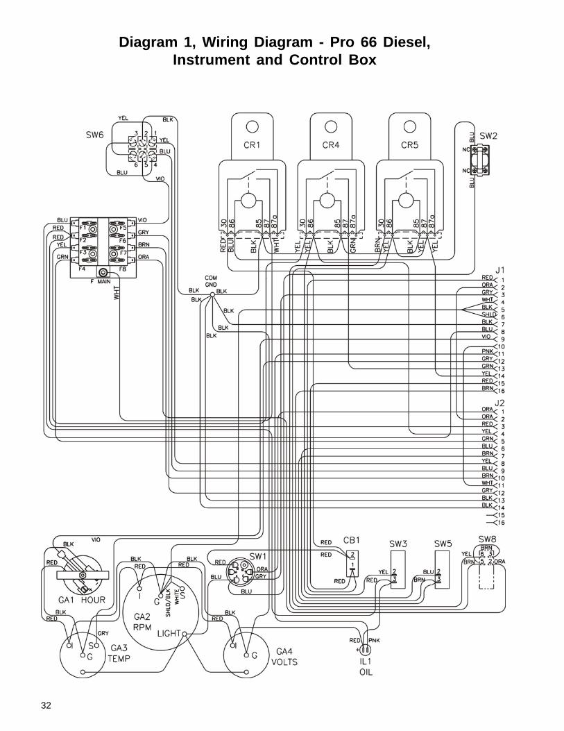
Diagram 1, Wiring Diagram - Pro 66 Diesel,Instrument and Control Box
33
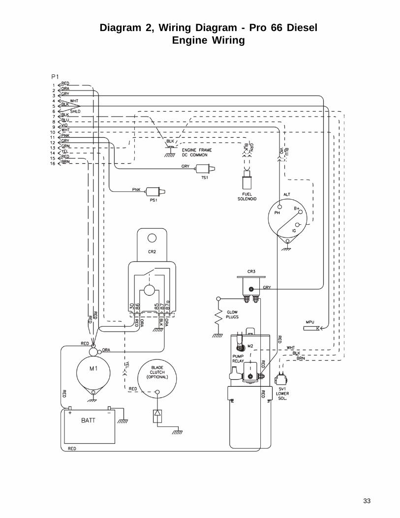
Diagram 2, Wiring Diagram - Pro 66 DieselEngine Wiring
34
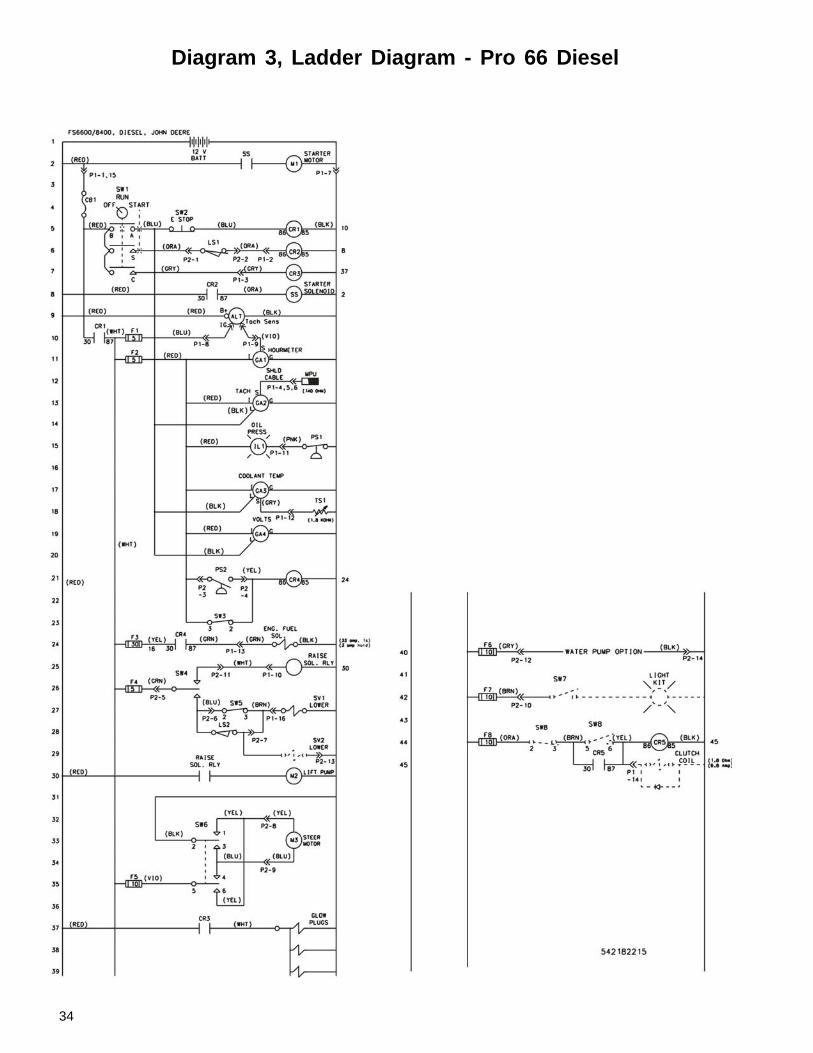
Diagram 3, Ladder Diagram - Pro 66 Diesel
35
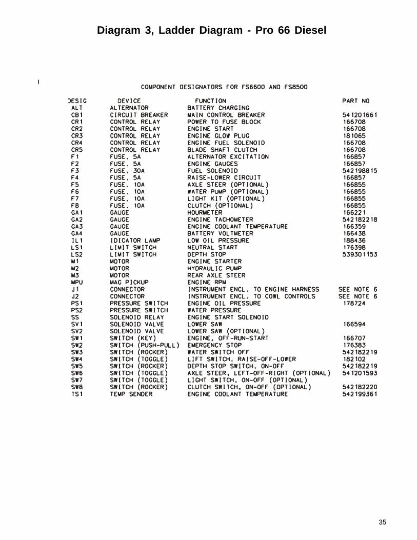
Diagram 3, Ladder Diagram - Pro 66 Diesel
36
Target Corporate Office17400 West 119th Street
Olathe, Kansas 66061Phone: 913-928-1000
Customer Service: 800-288-5040Customer Service Fax: 800-825-0028Corporate Office Fax: 913-438-7951
Customer Service, Int’l: 913-928-1258Cerritos, CA Warehouse: 562-404-6172
Cerritos, CA Warehouse Fax: 562-404-0953
Target Latin America, Mexico, Carribean,Central and South America
17400 West 119th StreetOlathe, Kansas 66061Phone: 913-928-1255
Fax: 913-438-7938
Target CanadaPhone: 800-323-3553
Fax: 888-323-3822
Warning!
Some dust created by power sanding, sawing, grinding, drillingand other construction activities contains chemicals known (tothe State of California) to cause cancer, birth defects or otherreproductive harm. Some examples of these chemicals are:
• Lead from lead based paints.• Crystalline silica from bricks and cement and other masonryproducts.• Arsenic and chromium from chemically-treated lumber.
Your risk from these exposures varies, depending on how oftenyou do this type of work. To reduce your exposure to thesechemicals, work in a well-ventilated area, and work with approvedsafety equipment such as those dust masks that are speciallydesigned to filter out microscopic particles.
www.targetblue.com
From the Electrolux Group. The world’s No. 1 choice.


![J M :Y &-% - alqabas.com · z"66)66a660 86666 9 n66 "66 '66 p,*r"6666666-, 866[66\66 * 666666]9b ^666$666)666U666-, 6666C6666 KB_66666666#66666666-, P,*RB 26666-/6666A6666L6666 ,](https://static.fdocuments.in/doc/165x107/5c5f725109d3f279448b46c2/j-m-y-z6666a660-86666-9-n66-66-66-pr6666666-8666666-6666669b.jpg)