Printed in U.S.A. © 2016 The Timken · PDF fileIndustrial Bearing Maintenance Manual...
164
Industrial Bearing Maintenance Manual
-
Upload
nguyenmien -
Category
Documents
-
view
215 -
download
1
Transcript of Printed in U.S.A. © 2016 The Timken · PDF fileIndustrial Bearing Maintenance Manual...

Industrial Bearing Maintenance Manual
Ind
ustrial B
earing
Main
tenan
ce Man
ual
The Timken team applies their know-how to improve the reliability and performance of machinery in diverse markets worldwide. The company designs, makes and markets high-performance mechanical components, including bearings, belts, gears, chain and related mechanical power transmission products and services.
www.timken.com
10M
09-
16 :2
9 Or
der N
o. 1
0213
|
Tim
ken®
is a
regi
ster
ed tr
adem
ark
of T
he T
imke
n Co
mpa
ny.
| ©
201
6 Th
e Ti
mke
n Co
mpa
ny
| P
rinte
d in
U.S
.A.

WARNINGFailure to observe the following warnings could
create a risk of serious injury.
Proper maintenance and handling practices are critical. Always follow installation instructions and
maintain proper lubrication.
Never spin a bearing with compressed air. The rolling elements may be forcefully expelled.
NOTEThis manual is not intended to substitue for the specific
recommendations of your equipment supplier.
Every reasonable effort has been made to ensure the accuracy of the information contained in this catalog, but no liability is
accepted for errors, omissions or for any other reason.
CAUTIONFailure to observe the following cautions could
create a risk of serious injury.
Do not attempt to disassemble unitized bearings.
Remove oil or rust inhibitor from parts before heating to avoid fire or fumes.
If a hammer and bar are used for installation or removal of a part, use a mild steel bar (e.g. 1010 or 1020 grade).
Mild steel bars are less likely to cause release of high speed fragments from the hammer, bar or the bering.

INDEXTIMKEN - WHERE YOU TURN. . . . . . . . . . . . . . . . . . . . . . . . . . . . . . . . . . 5
GENERAL BEARING HANDLING AND INSPECTION. . . . . . . . . . . . . . . 9
INTERNAL CLEARANCES . . . . . . . . . . . . . . . . . . . . . . . . . . . . . . . . . . . . 19
SHAFT AND HOUSING REQUIREMENTS . . . . . . . . . . . . . . . . . . . . . . . 31
SHAFT AND HOUSING TOLERANCES ABMA STANDARD 7 . . . . . . . 37
TAPERED ROLLER BEARINGS. . . . . . . . . . . . . . . . . . . . . . . . . . . . . . . . . 55
SPHERICAL ROLLER BEARINGS. . . . . . . . . . . . . . . . . . . . . . . . . . . . . . . 89
CYLINDRICAL ROLLER BEARINGS. . . . . . . . . . . . . . . . . . . . . . . . . . . . 101
THRUST BEARINGS . . . . . . . . . . . . . . . . . . . . . . . . . . . . . . . . . . . . . . . . 109
BALL BEARINGS . . . . . . . . . . . . . . . . . . . . . . . . . . . . . . . . . . . . . . . . . . . 117
MAINTENANCE TOOLS . . . . . . . . . . . . . . . . . . . . . . . . . . . . . . . . . . . . . 143
LUBRICATION AND SEALS . . . . . . . . . . . . . . . . . . . . . . . . . . . . . . . . . . 147
A
B
C
D
E
F
G
H
I
J
K
L
INDUSTRIAL BEARING MAINTENANCE MANUAL 3

TIMKEN - WHERE YOU TURN
INDUSTRIAL BEARING MAINTENANCE MANUAL4

TIMKEN - WHERE YOU TURNA TIMKEN - WHERE YOU TURNA
A

TIM
KEN - W
HERE YOU TURN
A
A

TIM
KEN - W
HERE YOU TURN
TIMKEN - WHERE YOU TURNMaintenance professionals around the world turn to Timken to help improve the performance and extend the life of their equipment. The information in this manual will help you follow proper industrial maintenance practices to get the most out of your Timken products and the equipment in which they operate. You will find practical information describing how to install, adjust, lubricate and maintain all of the primary types of anti-friction bearings. We have also included additional information on maintenance tools and proper lubrication.
ENGINEERING EXPERTISE
Timken has more than a century of experience developing bearings and related products that reduce friction, improve efficiency and minimize customer maintenance. Our advancements in bearing design, quality and materials create a customer advantage we call “power density.” This means we are increasing bearing load-carrying capability, enabling a smaller bearing to carry the same load for the same predicted life as a previously larger one. Power density gives equipment designers greater flexibility and leads to lower total system cost.
CUSTOMER SERVICE AND SUPPORT
Practices such as bearing mounting, adjustment and proper lubrication are very specific to an application. While we are not able to encompass every practice for every application in this manual, additional Timken publications and resources are available to assist with specialized tasks for a wide range of applications.
In addition, our Timken sales representatives are available to help you address unique bearing-related application problems. Backed by a global team of experts that include metallurgists, lubrication specialists, scientists, service engineers and customer service representatives, they comprise an unmatched technical resource for our customers.
A COMPLETE LINE OF FRICTION MANAGEMENT PRODUCTS AND SERVICES
Our friction management knowledge is being applied to a broader array of products and services than ever before. We have a total system approach to our engineering philosophy and our product and service offering, which impacts uptime, maintenance costs and your bottom line. Turn to us today for one of the world’s most complete friction management offerings, including:
• Condition Monitoring
• Lubrication
• Maintenance Tools
• Remanufacture and Repair
• Seals
• Training
TIMKEN - WHERE YOU TURN
INDUSTRIAL BEARING MAINTENANCE MANUAL 7
A

GENERAL BEARING HANDLIN
G AND INSPECTION
TIMKEN - WHERE YOU TURN
INDUSTRIAL BEARING MAINTENANCE MANUAL8
A

GENERAL BEARING HANDLIN
G AND INSPECTION
B GENERAL BEARING HANDLING AND INSPECTION
General Bearing Handling And Inspection . . . . . . . . . . . . . . . . 11
Bearing Storage . . . . . . . . . . . . . . . . . . . . . . . . . . . . . . . . . . . . . . . . 11
Removing Bearings From Equipment . . . . . . . . . . . . . . . . . . . . . 12
Damaged Bearings . . . . . . . . . . . . . . . . . . . . . . . . . . . . . . . . . . . . . 14
Installation . . . . . . . . . . . . . . . . . . . . . . . . . . . . . . . . . . . . . . . . . . . . . 14
Lubrication . . . . . . . . . . . . . . . . . . . . . . . . . . . . . . . . . . . . . . . . . . . . . 17
B
B

GEN
ERAL
BEA
RING H
ANDLING AND INSPECTION
BB

GEN
ERAL
BEA
RING H
ANDLING AND INSPECTION
GENERAL BEARING HANDLING AND INSPECTIONBearings are a vital component in major industrial equipment. Bearing problems can result in costly downtime, equipment damage and breakdowns. In addition, large industrial bearings represent a significant capital investment.
To attain reliable operation with high equipment performance and the lowest possible maintenance costs, it is essential to follow proper handling practices. This includes bearing storage, removal, cleaning, inspection and installation.
The useful life of any bearing depends to a great extent on the care and maintenance it receives. This is especially true in industrial applications, where operating conditions tend to be harsh, loads are heavy, and contamination from dirt and scale are common.
Details about specific handling and inspection processes for different types of bearings are included in those sections of this manual. This section addresses general processes and practices that apply to all anti-friction bearing designs.
BEARING STORAGE
Bearings with special anti-corrosion coatings are available, but most bearings are not manufactured from corrosion resistant materials. When handling and storing bearings, care must be taken to ensure that they will not rust or corrode. Even a small amount of moisture or chemical left on an unprotected bearing by a glove or hand can result in a small etched area, which may initiate bearing fatigue.
New and remanufactured Timken bearings are shipped with a protective coating, are typically covered in a protective paper or other wrapping, and are shipped in a carton or crate. When receiving a new or remanufactured bearing, do not remove it from its packaging until ready to install in the application.
Do not store bearings directly on concrete floors, where water can condense and collect on the bearing. Store the bearings on a pallet or shelf, in an area where the bearings will not be subjected to high humidity or sudden and severe temperature changes that may result in condensation forming.
Always put oiled paper or, if not available, plastic sheets between rollers and cup races of tapered roller bearings.
GENERAL BEARING HANDLING AND INSPECTION
INDUSTRIAL BEARING MAINTENANCE MANUAL 11
B

REMOVING BEARINGS FROM EQUIPMENT
Each type of bearing design has a unique removal process. Regardless of the bearing type, the bearing must be removed with extreme care. If done incorrectly, you can damage the bearings, shafts or housings, requiring expensive repairs.
For smaller bearings, there are a variety of pullers available to assist with bearing removal (Fig. 1). Information concerning special pullers or other removal devices can be obtained by contacting your Timken representative.
For bearings installed with a tight or press fit, or that have become locked in place on a shaft and cannot be removed with a mechanical puller, the inner ring of the bearing can be heated to ease removal. Heat lamps or other heating devices can be used. If a torch is used, it will change the properties of the bearing steel and the bearing must be discarded.
A clean, heavy duty nylon sling provides one of the best means of handling large bearing components because it eliminates the possibility of burring or scratching.
Regardless of what method is used to lift the bearings, use care to avoid damaging any of the bearing surfaces. Be especially cautious when lifting or moving bearings that are equipped with a cage. The cage is typically the most deformable component of the bearing and is more susceptible to damage.
Cleaning
After removing a bearing from a piece of equipment, thoroughly clean it to remove all scale, water, lubricant, debris and any other contaminants. Bearings must be cleaned thoroughly to allow for proper bearing inspection.
Smaller bearings can be cleaned in a wash tank that circulates a cleaning solution such as kerosene, mineral spirits or a commercial solvent through the bearing (Fig. 3). Use the cleaning solution to remove all lubricant and contamination, making sure that the internal rolling elements are completely clean.
Fig . 2 . Eyebolts can be inserted into lifting holes .
Fig . 1 . Pullers for bearing removal .
CAUTION Failure to observe the followingcautions could create a risk of injury.
If the bearing is to be reused or returned for repair, do not use heat from a torch.
Extreme heat from a torch can alter the bearing hardness and metallurgical structure, resulting in irreparable damage.
WARNING Failure to observe the followingwarnings could create a risk of serious bodily harm.
Tensile stresses can be very high in tightly fitted bearing components. Attempting to remove such components by cutting
the cone (inner race) may result in a sudden shattering of the component causing fragments of metal to be forcefully expelled.
Always use properly guarded presses or bearing pullers to remove bearings from shafts, and always use suitable personal
protective equipment, including safety glasses.
Lifting large bearings
Large bearings can be lifted and moved using a variety of slings, hooks, chains and mechanical devices. Some large bearings are manufactured with tapped holes in the face of inner rings or outer rings. Eyebolts or other points of attachment can be inserted in these lifting holes (Fig. 2).
Many large bearings have threaded lifting holes in the cage ring that can be used to lift the inner ring assembly.
GENERAL BEARING HANDLING AND INSPECTION
INDUSTRIAL BEARING MAINTENANCE MANUAL12
B

Fig . 3 . Smaller bearings can be cleaned in a wash tank .Fig . 4 . Tanks are heated with electric coils and a pump is used to agitate the cleaning solution .
Alkali cleaners, such as trisodium phosphate (TSP) mixed two or three ounces per gallon of hot water, may also be used. Hot cleaning solutions are often used as a final cleaning or rinse after the initial cleaning.
For large bearings, or to clean large numbers of bearings, special cleaning equipment such as a large tank containing appropriate cleaning solution is required. Tanks are typically heated with electrical coils, and a pump is used to agitate the cleaning solution (Fig. 4). Final cleaning is done by suspending the bearing and using a hose to flush away any contamination.
To reduce bearing contamination from other sources, all parts of the housing, shaft and gears should also be thoroughly cleaned. After the bearing has been cleaned, it can be dried with compressed air, taking care not to let the bearing spin.
After cleaning, the bearing should be carefully inspected for damage and wear. If the bearing is not going to be returned to service immediately, it should be covered with a coating of light oil to protect against rust and corrosion.
WARNING Failure to observe the followingwarnings could create a risk of serious bodily harm.
Proper maintenance and handling practices are critical. Failure to follow installation instructions and to maintain
proper lubrication can result in equipment failure.
Never spin a bearing with compressed air. The rolling elements may be forcefully expelled.
Inspection
When a piece of equipment is taken out of service for routine inspection or maintenance, take the opportunity to also inspect and measure the bearings to ensure that they are still within tolerance specifications for the application. In some applications, the expected bearing life may be the limiting factor in the equipment maintenance schedule.
The schedule for equipment tear downs for bearing inspection will vary depending on operating conditions. Consult your equipment maker for the appropriate inspection schedule.
Between equipment tear downs where full bearing inspections are conducted, you should conduct routine inspections to ensure that bearings are operating normally and have proper lubrication. To reduce the need for these inspections, and to more closely monitor bearing and equipment health, Timken condition monitoring systems are available that sense the vibration and temperature in bearings.
The inspection area must be clean and free from dirt and debris to avoid contaminating the bearing. Even a small piece of debris that enters a bearing can create a point of high stress that could lead to spalling and early fatigue.
GENERAL BEARING HANDLING AND INSPECTION
INDUSTRIAL BEARING MAINTENANCE MANUAL 13
B

In addition to examining the bearing, a full inspection should include the housing and shaft. Check for burrs or metal chips on the inner and outer ring seats and backing surfaces (Fig. 5). Burrs or chips can be removed by scraping or filing the damaged surfaces.
Inspect the shaft for proper size, roundness, burrs or other damage. A 12-point check of the shaft with a micrometer is suggested (see page 33). If there is evidence of shaft or housing wear, it should be checked against original equipment manufacturer’s specifications.
valuable clues that can help analyze and identify possible causes, leading to corrective actions that will help ensure longer bearing life in the replacement bearing.
There are several Timken resources available to assist you in analyzing bearing damage, including online resources at timken.com and publications with photos representing common types of bearing damage. Contact your Timken representative for more information.
Bearing repair
Small areas of damage on bearing races, and on the contact surface of the rolling elements, can sometimes be repaired by grinding out the loose metal. Any raised or rough areas should be smoothed flat with grinding and polishing tools.
Light rust or corrosion should be removed with emery paper (240 – 320 # grit). As much of the damage should be removed as possible to prevent it from contaminating the bearing when it is returned to service.
For more complex bearing repairs, Timken offers remanufacture and repair services.
INSTALLATION
Do not remove the bearing from its packaging until you are ready to mount it. The packaging provides protection from contamination.
When installing a new bearing, do not remove the lubricant or preservative applied by the manufacturer. The preservatives used on almost all bearings are fully compatible with commonly used oils and other lubricants. Leaving it in place will protect the bearing from fingerprints and corrosion.
Bearings should be installed in a clean environment, free from dust, debris, moisture and other contaminants. When installing a bearing in the field, make an effort to ensure a clean work area. Use protective screens around the work area, and provide a clean resting surface for the bearing and other components until they can be installed.
Before beginning the installation, plan your work. Be certain that you have the correct replacement bearing and necessary additional components. Also determine what tools will be required, including adjustment tools if appropriate, and have them on hand. Finally, if the bearing needs to be lubricated as part of the installation process, have the appropriate lubricants and tools available. Planning your work will enable you to perform the installation more quickly with few delays, shortening the amount of time the bearing is out of the equipment and exposed to contamination and possible handling damage.
CAUTION Failure to observe the followingcautions could create a risk of injury.
Do not attempt to disassemble unitized bearings.
Remove oil or rust inhibitor from parts before heating to avoid fire or fumes.
If a hammer and bar are used for installation or removal of a part, use a mild steel bar (e.g. 1010 or 1020 grade). Mild steel bars are less likely to cause release of high speed fragments
from the hammer, bar or the bearing.
Fig . 5 . It is important to check for burrs on the inner and outer ring seats and backing surfaces .
Chips on the bearing seat are trapped between face of bearing and shoulder
Burrs on shoulder or bearing seat
DAMAGED BEARINGS
Despite taking proper precautions, bearings may become damaged either through improper storage and handling or through normal wear in use. Bearings that have been damaged or are no longer within specifications may still be returned to service after repair or refurbishment. Some bearings can be refurbished more than once. Eventually all bearings will sustain sufficient wear or damage and will have to be replaced.
If a bearing is damaged or worn beyond repair sooner than expected, do not discard it. The nature of the damage can provide
GENERAL BEARING HANDLING AND INSPECTION
INDUSTRIAL BEARING MAINTENANCE MANUAL14
B

Thoroughly clean all machine components near where the bearing will be installed, giving special attention to the mounting surfaces and housings. Housings should be cleaned, including blowing out the oil holes. If the equipment has blind holes where air is ineffective, use a magnetic rod to remove metal chips that might have become lodged there during machining or maintenance.
Shaft surfaces that will support and contact the bearing must be clean and free from nicks or burrs. Shaft shoulders and spacer rings contacting the bearing should be square with the shaft axis. The shaft fillet must be small enough to clear the radius of the bearing.
Do not install bearings in a damaged or worn housing, or on a damaged or worn shaft. Inner and outer ring seat damage should be repaired by using properly fitted sleeves. Shafts can be built up by metal spray and machined to the correct size. If there is not a press fit on the shaft, a weld overlay and re-grind process is recommended to bring the shaft back to specification.
Heating bearings
In applications that require a tight fit of the inner ring on the shaft, it can be easier to install the bearing if it is first heated to expand slightly. For applications that require a tight fit of the outer ring in a housing, it may also be possible to heat the housing to expand it, allowing the bearing to install more easily.
Small bearings can be heated using several methods. They can be heated in a pan or metal container filled with oil (Fig. 6). A screen or platform should be used to keep the bearing from resting on the bottom of the pan where heat is applied.
Fig . 6 . Bearings can be heated in a pan or metal container filled with oil .
Fig . 7 . Induction heater .
Flame burnerBearing held from bottom by screen
Bearing Bearing support blockOil
Fig . 8 . Oil bath .
Bearing held from bottom by screen/platform
Flame burner
Bearing
Oil
Bearing support block
A heat lamp can also be used to heat rings, and the temperature regulated by adjusting the distance from the light to the ring.
The fastest method of safely heating bearings is an induction heater (Fig. 7). Induction heaters work very quickly. Take care to avoid heating the bearing to temperatures higher than 120ºC (250ºF).
For larger bearings, you may need to use an oil bath to heat the bearing (Fig. 8). Maximum temperature of the oil bath should not exceed 120ºC (250ºF). The bearing should be positioned in the center of the tank, and allowed to heat long enough to fully expand. Do not allow the bearing to come in direct contact with the heat source.
GENERAL BEARING HANDLING AND INSPECTION
INDUSTRIAL BEARING MAINTENANCE MANUAL 15
B

Keep the bearings away from any localized high-heat source that may raise the bearing temperature too high, resulting in race hardness reduction.
When heating bearings, be sure that they have enough time to fully heat. Bearings typically require 20 to 30 minutes of soak time per inch of inner-ring cross section to fully heat in an oil tank.
While the bearing is still warm, remove it from the heater or tank and place it on the shaft. Slide the bearing up the shaft until it squarely contacts the shaft shoulder. Then install the locknut/washer or clamping plate to prevent the bearing from backing off the shoulder while cooling. As the bearing cools, the locknut or clamping plate should be tightened.
Thermal growth of components can be calculated using the formula:
d x ΔT x α = Thermal Growth
Where:
d = bearing bore diameter
ΔT = maximum bearing temperature after heating minus ambient temperature
α = coefficient of linear expansion: 11 x 10-6/ ºC (6.1 x 10⁻⁶/ ºF) for ferrous metal shaft and housing materials
Sample calculation
Example:
For a bearing with a 3-1/2 in. bore heated from an ambient temperature of 70° F to 200° F, the thermal growth of the bearing bore diameter can be calculated as follows:
Thermal Growth = 3.500” x (200° - 70°) x 6.1x10-6 = 0.0028 in.
For a bearing with a 90 mm bore heated from an ambient temperature of 21° C to 93° C:
Thermal Growth = 90 mm x (93° - 21°) x 11x10-6 = 0.071 mm
TEMPERATURE GUIDELINES FOR HEATING OR COOLING ROLLING ELEMENT BEARINGS FOR INSTALLATION
These maximum and minimum temperatures, as well as maximum time-at-temperature limits, have been established to prevent metallurgical transformation of steel components, and potential, detrimental physical changes in seals or non-metallic components. During the manufacturing process, bearing rings and rolling elements are heat treated to define the strength, hardness and dimensional stability for proper operation. Heating or cooling bearings or bearing components beyond these limits may affect performance.
These suggestions are merely guidelines and, as new data is developed, the values as shown may change. These guidelines do not cover all Timken® products.
CAUTION Failure to observe the followingcautions could create a risk of injury.
If the bearing is to be reused or returned for repair, do not use heat from a torch.
Extreme heat from a torch can alter the bearing hardness and metallurgical structure, resulting in irreparable damage.
Heating
Standard class bearings or rings (with metallic cages and with-out seals):
• Include Class 2, 4, 7, K, N, ABEC-1 and ABEC-3
• 93°C (200°F) - 24 Hours
• 121°C (250°F) - 8 Hours
Precision bearings or rings (with non-metallic cages and poly-mer or elastomer seals):
• Special considerations may apply for phenolic cages or spe-cial fluorocarbon lip seals.
• Include Class 3, 0, 00, 000, C, B, A, AA, ABEC 5 and 7
Precision and superprecision class bearings and rings (any)
• 66°C (150°F) - 24 Hours
NOTE: Always use protective safety equipment and clothing when handling parts that have been heated or cooled.
Never heat a bearing with a torch, as localized heating will irreparably damage bearing components.
Never rapidly heat or freeze a bearing or bearing component.
Only use approved equipment, methods and controls to achieve desired temperature.
Always follow OEM instructions to ensure bearings and rings are properly positioned after heating or cooling.
GENERAL BEARING HANDLING AND INSPECTION
INDUSTRIAL BEARING MAINTENANCE MANUAL16
B

Cone bore temperature reading in degrees
Cooling (Freezing)
Freezing standard class bearings and rings
• 54°C (-65°F) - 1 Hour
Freezing precision class outer rings or cups
• -29°C (-20°F) - 2 Hours
Note: This temperature can be obtained by commercial freezer/refrigeration equipment.
GENERAL BEARING HANDLING AND INSPECTION
INDUSTRIAL BEARING MAINTENANCE MANUAL 17
B
Cone Bore
Thermometer Temperature Reading in Degrees
Cone Bore
Thermometer Temperature Reading in Degrees
65º C 150º F
90º C 200º F
120º C 250º F
65º C 150º F
90º C 200º F
120º C 250º F
mm in.
mm in.
mm in.
mm in.
mm in.
mm in.
mm in.
mm in.
25 .4 0 .012 0 .020 0 .027 482 .6 0 .231 0 .375 0 .5201 0.0005 0.0008 0.0011 19 0.0091 0.0148 0.0205
50 .8 0 .025 0 .040 0 .055 508 0 .243 0 .396 0 .5482 0.0010 0.0016 0.0022 20 0.0096 0.0156 0.0216
76 .2 0 .036 0 .058 0 .081 533 .4 0 .256 0 .416 0 .5763 0.0014 0.0023 0.0032 21 0.0101 0.0164 0.0227
101 .6 0 .048 0 .078 0 .109 558 .8 0 .269 0 .436 0 .6044 0.0019 0.0031 0.0043 22 0.0106 0.0172 0.0238
127 0 .061 0 .099 0 .137 584 .2 0 .279 0 .454 0 .6295 0.0024 0.0039 0.0054 23 0.011 0.0179 0.0248
152 .4 0 .073 0 .119 0 .165 609 .6 0 .292 0 .475 0 .6576 0.0029 0.0047 0.0065 24 0.0115 0.0187 0.0259
177 .8 0 .086 0 .139 0 .193 635 0 .304 0 .495 0 .6857 0.0034 0.0055 0.0076 25 0.012 0.0195 0.027
203 .2 0 .096 0 .157 0 .218 660 .4 0 .317 0 .515 0 .7138 0.0038 0.0062 0.0086 26 0.0125 0.0203 0.0281
228 .6 0 .109 0 .177 0 .246 685 .8 0 .330 0 .535 0 .7419 0.0043 0.0070 0.0097 27 0.013 0.0211 0.0292
254 0 .121 0 .198 0 .274 711 .2 0 .340 0 .553 0 .76710 0.0048 0.0078 0.0108 28 0.0134 0.0218 0.0302
279 .4 0 .134 0 .218 0 .302 736 .6 0 .353 0 .574 0 .79511 0.0053 0.0086 0.0119 29 0.0139 0.0226 0.0313
304 .8 0 .147 0 .238 0 .330 762 0 .365 0 .594 0 .82312 0.0058 0.0094 0.013 30 0.0144 0.0234 0.0324
330 0 .157 0 .256 0 .355 787 .4 0 .378 0 .614 0 .8513 0.0062 0.0101 0.014 31 0.0149 0.0242 0.0335
355 .6 0 .170 0 .276 0 .383 812 .8 0 .391 0 .635 0 .87814 0.0067 0.0109 0.0151 32 0.0154 0.025 0.0346
381 0 .182 0 .297 0 .411 838 .2 0 .401 0 .652 0 .90415 0.0072 0.0117 0.0162 33 0.0158 0.0257 0.0356
406 .4 0 .195 0 .317 0 .439 863 .6 0 .414 0 .673 0 .93216 0.0077 0.0125 0.0173 34 0.0163 0.0265 0.0367
431 .8 0 .208 0 .337 0 .467 889 0 .426 0 .693 0 .96017 0.0082 0.0133 0.0184 35 0.0168 0.0273 0.0378
457 .2 0 .218 0 .355 0 .492 914 .4 0 .439 0 .713 0 .98818 0.0086 0.014 0.0194 36 0.0173 0.0281 0.0389

INTERNAL CLEARANCES
Pressing on bearings
Smaller bearings may be pressed onto the shaft or into a housing with an arbor press and mounting tube. Between the press ram and the bearing, use a tube of soft steel with an inside diameter slightly larger than the shaft. The outside diameter of the tube should not exceed the maximum shoulder height for the bearings. The tube should be square at both ends, thoroughly clean inside and out, and long enough to clear the end of the shaft after the bearing is mounted.
• Inspect the shaft and housing for proper size, roundness, burrs or other damage. A 12-point check of the shaft with a micrometer is suggested (see page 33).
• Coat the shaft with light machine oil or assembly paste to reduce the force needed to press the bearing on the shaft.
• Use a tube or pipe with an inner diameter (I.D.) that is slightly larger than the outer diameter (O.D.) of the shaft. The O.D. of the tube or pipe should be small enough that it does not contact the rolling elements or cage of the bearing.
• Position the tube on the inner ring and apply steady pressure with sufficient force to smoothly press the ring into place, and firmly against the shoulder or backing surface (Fig. 9).
Never attempt to make a press fit on a shaft by applying pressure to the outer ring of an assembled bearing. However, because they have a separable outer ring, the outer ring of tapered roller bearings can be pressed into a housing. See page 61.
For specific information regarding bearing installation in your equipment, contact the equipment manufacturer.
Fig . 9 . Positioning the tube on the inner ring .
Adjusting bearing clearance
The space between the rolling elements and the races of an anti-friction bearing is known as the bearing clearance, referred to in tapered roller bearings as the lateral, lateral clearance or end play. In other types of anti-friction bearings such as spherical, cylindrical, or ball bearings, the radial internal clearance or RIC, is specified. Clearance is desirable in applications where allowance must be provided for thermal growth of components, to accommodate for slight misalignment or other application requirements.
Bearings may also have zero clearance, with the contact surfaces of the rolling elements brought into contact with the races in line-to-line contact.
Finally, bearings may have the rolling elements and races brought into contact with a defined initial force, a condition known as preload. This enables precise control over the internal geometry of the mating parts, and is desirable where runout must be held within critical limits, such as high precision applications.
Bearings with separable races, such as tapered roller bearings, allow the clearance (preload) to be “adjusted” to meet application requirements. Other types of bearings are manufactured with a known clearance or preload, but the clearance can be slightly reduced through an interference fit on the inner or outer race.
For information about adjusting various types of bearings, see the section of this manual for each bearing design.
LUBRICATION
See the Lubrication Section of this manual beginning on page 155.
GENERAL BEARING HANDLING AND INSPECTION
INDUSTRIAL BEARING MAINTENANCE MANUAL18
B

INTERNAL CLEARANCESC INTERNAL CLEARANCES
Tapered Roller Bearings . . . . . . . . . . . . . . . . . . . . . . . . . . . . . . . . . 21
Radial Ball Bearings . . . . . . . . . . . . . . . . . . . . . . . . . . . . . . . . . . . . 22
Spherical Roller Bearings . . . . . . . . . . . . . . . . . . . . . . . . . . . . . . . 25
Cylindrical Roller Bearings . . . . . . . . . . . . . . . . . . . . . . . . . . . . . . 27
C
C

INTE
RNAL CLEARANCES
CC

Bearing setting obtained during initial assembly and adjustment is the cold or ambient bearing setting and is established before the equipment is subjected to service.
Bearing setting during operation is known as the operating bearing setting and is a result of changes in the ambient bearing setting due to thermal expansion and deflections encountered during service.
The ambient bearing setting necessary to produce the optimum operating bearing setting varies with the application. Application experience, or testing, generally permits the determination of optimum settings. Frequently, however, the exact relationship of ambient to operating bearing setting is an unknown and an educated estimate has to be made. To determine a suggested ambient bearing setting for a specific application, consult with your Timken representative.
Generally, the ideal operating bearing setting is near zero to maximize bearing life. Most bearings are set with end play at assembly to reach the desired near zero setting at operating temperature when mounted.
INTERNAL CLEARANCES
TAPERED ROLLER BEARINGS
In tapered roller bearings, internal clearance is usually defined as a specific amount of either end play or preload. Establishing this clearance, or setting, at the time of assembly is an inherent advantage of tapered roller bearings. They can be set to provide optimum performance in almost any application. Fig. 10 gives an example of the relationship between fatigue life and bearing setting. Unlike some types of anti-friction bearings, tapered roller bearings do not rely strictly on housing or shaft fits to obtain a certain bearing setting. One race can be moved axially relative to the other to obtain the desired bearing setting.
At assembly, the conditions of bearing setting are defined as:
• End play – An axial clearance between rollers and races pro-ducing a measurable axial shaft movement when a small axial force is applied - first in one direction, then in the other, while oscillating or rotating the shaft (Fig. 11).
• Preload – An axial interference between rollers and races such that there is no measurable axial shaft movement when a small axial force is applied - in both directions, while oscil-lating or rotating the shaft.
• Line-to-line – A zero setting condition; the transitional point between end play and preload.
INTE
RNAL CLEARANCES
Fig . 11 . Axial force is applied in both directions while rotating the shaft .
0
Zero Clearance
Light preloadLarge end play
L10 life
Heavy preload
Bearing operating setting
Preload End play
Axial end play
Axial end play
Fig . 10 . Relationship between fatigue life and bearing setting .
INTERNAL CLEARANCES
INDUSTRIAL BEARING MAINTENANCE MANUAL 21
C

Limits for radial internal clearance of single-row, radial contact ball bearings under no load
(Applies to bearings of ABEC-1, ABEC-3, ABEC-5, ABEC-7, and ABEC-9 Tolerances)
RADIAL BALL BEARINGS
In the manufacture of ball bearings, it is standard practice to assemble rings and balls with a specified internal clearance. This characteristic is necessary to absorb the effect of press fitting the bearing rings at mounting.
Internal clearances sometimes are used to compensate for thermal expansion of bearings, shafts and housings or to provide a contact angle in the bearing after mounting. Internal clearance can be measured either by gaging radially or axially.
Radial measurement is accepted as the more significant characteristic because it is more directly related to shaft and housing fits. It also is the method prescribed by the American Bearing Manufacturers Association (ABMA).
Radial internal clearance
The radial internal clearance (RIC) of a radial contact ball bearing can be defined as the average outer ring raceway diameter minus
the average inner ring raceway diameter minus twice the ball diameter.
RIC can be measured mechanically by moving the outer ring horizontally as pictured in Fig. 12. The total movement of the outer ring when the balls are properly seated in the raceways determines the radial internal clearance. Several readings should be taken using different circumferential orientations of the rings in order to get a comprehensive average reading.
Fig . 12 . RIC can be measured mechanically by moving the outer ring horizontally .
Timken® Prefix(ABMA designation) H (C2) R (C0) P (C3) J (C4) JJ (C5)
Basic Bore Diametermm
Acceptance Limits Acceptance Limits Acceptance Limits Acceptance Limits Acceptance Limits
Max. Min. Max. Min. Max. Min. Max. Min. Max. Min.
over incl. mmin.
mmin.
mmin.
mmin.
mmin.
mmin.
mmin.
mmin.
mmin.
mmin.
2 .5 10 0 .0070.0003
0 .0000.0000
0 .0130.0005
0 .0020.0001
0 .0230.0009
0 .0080.0003
0 .0290.0011
0 .0140.0006
0 .0370.0015
0 .0200.0008
10 18 0 .0090.00035
0 .0000.0000
0 .0180.0007
0 .0030.0001
0 .0250.001
0 .0110.0004
0 .0330.0013
0 .0180.0007
0 .0450.0018
0 .0250.0010
18 24 0 .0100.0004
0 .0000.0000
0 .0200.0008
0 .0050.0002
0 .0280.0011
0 .0130.0005
0 .0360.0014
0 .0200.0008
0 .0480.0019
0 .0280.0011
24 30 0 .0110.00045
0 .0010.0001
0 .0200.0008
0 .0050.0002
0 .0280.0011
0 .0130.0005
0 .0410.0016
0 .0230.0009
0 .0530.0021
0 .0300.0012
30 40 0 .0110.00045
0 .0010.0001
0 .0200.0008
0 .0060.0002
0 .0330.0013
0 .0150.0006
0 .0460.0018
0 .0280.0011
0 .0640.0025
0 .0400.0016
40 50 0 .0110.00045
0 .0010.0001
0 .0230.0009
0 .0060.00025
0 .0360.0014
0 .0180.0007
0 .0510.0020
0 .0300.0012
0 .0730.0029
0 .0450.0018
50 65 0 .0150.0006
0 .0010.0001
0 .0280.0011
0 .0080.00035
0 .0430.0017
0 .0230.0009
0 .0610.0024
0 .0380.0015
0 .0900.0035
0 .0550.0022
65 80 0 .0150.0006
0 .0010.0001
0 .0300.0012
0 .0100.0004
0 .0510.0020
0 .0250.0010
0 .0710.0028
0 .0460.0018
0 .1050.0041
0 .0650.0026
Continued on next page.
INTERNAL CLEARANCES
INDUSTRIAL BEARING MAINTENANCE MANUAL22
C

Timken® Prefix(ABMA designation) H (C2) R (C0) P (C3) J (C4) JJ (C5)
Basic Bore Diametermm
Acceptance Limits Acceptance Limits Acceptance Limits Acceptance Limits Acceptance Limits
Max. Min. Max. Min. Max. Min. Max. Min. Max. Min.
over incl. mmin.
mmin.
mmin.
mmin.
mmin.
mmin.
mmin.
mmin.
mmin.
mmin.
80 100 0 .0180.0007
0 .0010.0001
0 .0360.0014
0 .0120.00045
0 .0580.0023
0 .0300.0012
0 .0840.0033
0 .0530.0021
0 .1200.0047
0 .0750.0030
100 120 0 .0200.0008
0 .0020.0001
0 .0410.0016
0 .0150.0006
0 .0660.0026
0 .0360.0014
0 .0970.0038
0 .0610.0024
0 .1400.0055
0 .0900.0035
120 140 0 .0230.0009
0 .0020.0001
0 .0480.0019
0 .0180.0007
0 .0810.0032
0 .0410.0016
0 .1140.0045
0 .0710.0028
0 .1600.0063
0 .1050.0041
140 160 0 .0230.0009
0 .0020.0001
0 .0530.0021
0 .0180.0007
0 .0910.0036
0 .0460.0018
0 .1300.0051
0 .0810.0032
0 .1800.0071
0 .1200.0047
160 180 0 .0250.0010
0 .0020.0001
0 .0610.0024
0 .0200.0008
0 .1020.0040
0 .0530.0021
0 .1470.0058
0 .0910.0036
0 .2000.0079
0 .1350.0053
180 200 0 .0300.0012
0 .0020.0001
0 .0710.0028
0 .0250.0010
0 .1170.0046
0 .0630.0025
0 .1630.0064
0 .1070.0042
0 .2300.0091
0 .1500.0059
200 240 0 .0360.0014
0 .0030.0001
0 .0810.0032
0 .0300.0012
0 .1370.0054
0 .0740.0029
0 .1930.0076
0 .1270.0050
0 .2670.0105
0 .1830.0072
240 280 0 .0410.0016
0 .0030.0001
0 .0970.0038
0 .0330.0013
0 .1570.0062
0 .0860.0034
0 .2240.0088
0 .1470.0058
0 .3100.0122
0 .2130.0084
280 320 0 .0480.0019
0 .0050.0002
0 .1140.0045
0 .0410.0016
0 .1800.0071
0 .1040.0041
0 .2570.0101
0 .1700.0067
0 .3530.0139
0 .2460.0097
320 370 0 .0530.0021
0 .0050.0002
0 .1270.0050
0 .0460.0018
0 .2080.0082
0 .1170.0046
0 .2950.0116
0 .1980.0078
0 .4090.0161
0 .2840.0112
370 430 0 .0640.0025
0 .0080.0003
0 .1470.0058
0 .0560.0022
0 .2410.0095
0 .1370.0054
0 .3400.0134
0 .2310.0091
0 .4750.0187
0 .3300.013
430 500 0 .0740.0029
0 .0100.0004
0 .1700.0067
0 .0660.0026
0 .2790.0110
0 .1600.0063
0 .3960.0156
0 .2690.0106
0 .5510.0217
0 .3860.0152
500 570 0 .0810.0032
0 .0100.0004
0 .1930.0076
0 .0740.0029
0 .3180.0125
0 .1830.0072
0 .4500.0177
0 .3070.0121
0 .6300.0248
0 .4390.0173
570 640 0 .0910.0036
0 .0130.0005
0 .2160.0085
0 .0850.0033
0 .3560.0140
0 .2060.0081
0 .5050.0199
0 .3450.0136
0 .7060.0278
0 .4950.0195
640 710 0 .1140.0045
0 .0200.0008
0 .2390.0094
0 .1070.0042
0 .3940.0155
0 .2290.0090
0 .5640.0222
0 .3840.0151
0 .7800.0307
0 .5540.0218
710 800 0 .1400.0055
0 .0200.0008
0 .2690.0106
0 .1300.0051
0 .4450.0175
0 .2590.0102
0 .6300.0248
0 .4340.0171
0 .8790.0346
0 .6200.0244
800 1060 0 .2110.0083
0 .0280.0011
0 .3530.0139
0 .2010.0079
0 .5870.0231
0 .3450.0136
0 .8330.0328
0 .5770.0227
1 .1480.0452
0 .8230.0324
: Standard fits for Timken radial ball bearings. P(C3) for bearing O.D. greater than 52 mm.
INTERNAL CLEARANCES
INDUSTRIAL BEARING MAINTENANCE MANUAL 23
C

End Play
End play is an alternate method of measuring internal clearance and is rarely used except for certain special applications. End play is determined by mounting the bearing, as shown in Fig. 13, with one of its rings clamped to prevent axial movement. A reversing measuring load is applied to the unclamped ring so the resulting movement of that ring is parallel to the bearing axis. End play is the total movement of the unclamped ring when the load is applied first in one direction and then in the other.
Fig . 13 . End play is determined by mounting the bearing with one of its rings clamped .
Timken BearingNumber Prefix ISO/ABMA Symbol Description
H C2
Snug fit; slight internal clearance; sometimes used to achieve a minimum of radial or axial play in an assembly.
Example: H204K
R C0Medium fit; internal clearance generally
satisfactory with recommended shaft and housing fits. Example: RMM204K.
P C3
Loose fit; considerable internal clearance required for applications
involving press fits on both inner and outer rings, extra interference fits, or temperature differentials. Example:
P204K.
J C4
Extra loose fit; large amount of internal clearance for applications involving
large interference fits or temperature differentials. Example: J204K.
JJ C5
Extra-extra loose fit; extra large amount of internal clearance for applications
with large temperature differential and interference fits on both rings.
Table 1 . Radial clearance designations correlate with ISO/ABMA symbols .
INTERNAL CLEARANCES
INDUSTRIAL BEARING MAINTENANCE MANUAL24
C

SPHERICAL ROLLER BEARINGS
RIC is the radial internal clearance or radial play within a bearing. The bearing’s RIC allows a tight fit, with sufficient internal clearance after installation for normal operating conditions.
Spherical roller bearings with tapered bore (K) require a slightly greater interference fit on the shaft than a cylindrical bore bearing. The effect of this greater interference fit is a reduction of RIC. For tapered bore bearings, it is critical to select the RIC that allows for this reduction.
Example #1 - Calculating RIC Reduction Using a Spherical Roller Bearing with Tapered Bore
Given bearing number 22328K C3 (140 mm bore with a C3 clearance) is to be mounted on a tapered shaft. Using a set of feeler gauges, RIC is found to be –
RIC = 0.178 mm (0.007 in.)
Suggested Reduction of RIC Due to Installation = 0.064 to 0.089 mm (0.0025 in. to 0.0035 in.), found in chart on page 26.
Calculate the clearance after mounting –
0.178 mm - 0.077 mm = 0.101 mm or
0.007 in. - 0.003 in. = 0.004 in.
NOTE: For this example, the value of 0.077 mm (0.003 in.) was obtained by taking the mid-range value of the upper and lower limits found in the table on page 26.
Therefore, the locking nut should be tightened until RIC reaches 0.101 mm (0.004 in.).
It should also be noted that the value obtained by reading the Suggested RIC after Installation directly from the table on page 97 is 0.075 mm (0.0030 in.). This differs from the value calculated in the above example. The value taken directly from the table is provided as a minimum value. It is not suggested to use a calculated value that falls below this minimum.
Several factors influence RIC reduction. Inner rings pressed onto solid steel shafts expand approximately 80 percent of the interference fit. Outer rings pressed into steel or cast iron housings reduce RIC by about 60 percent of the interference fit. For RIC reduction on hollow shafts or non-steel materials, consult a Timken representative.
Timken® brand bearings are supplied with normal RIC, unless specified otherwise. The desired RIC code must be added to the bearing number, following all other suffixes.
Minimum/maximum values for each RIC are shown in the two adjacent columns directly beneath the selected RIC. For example, the minimum values shown for C5 are also the maximum values for C4; minimum values for C4 are also the maximum values for C3; etc.
Radial internal clearance limits - radial spherical roller bearings
(1) For bearings with normal initial clearance.
Bore(Nominal)
mm
Cylindrical Bore Tapered Bore
Suggested Reduction of RIC
Due to Installation
Sugg
este
d RI
Caf
ter I
nsta
llatio
n (1
)
Normal CO C4 Normal CO C4
Min. Max. Min. Max. Min. Max. Min. Max.
C2 C3 C5 C2 C3 C5
Min. Max. Min. Max. Min. Max. Min. Max. Min. Max. Min. Max. Min. Max. Min.
Over Incl. mmin.
mmin.
mmin.
mmin.
mmin.
mmin.
mmin.
mmin.
24 30 0 .0150.0006
0 .0250.0010
0 .0400.0016
0 .0550.0022
0 .0750.0030
0 .0950.0037
0 .0200.0008
0 .0300.0012
0 .0400.0016
0 .0550.0022
0 .0750.0030
0 .0950.0037
0 .0150.0006
0 .0200.0008
0 .0150.0006
30 40 0 .0150.0006
0 .0300.0012
0 .0450.0018
0 .0600.0024
0 .0800.0031
0 .1000.0039
0 .0250.0010
0 .0350.0014
0 .0500.0020
0 .0650.0026
0 .0850.0033
0 .1050.0041
0 .0200.0008
0 .0250.0010
0 .0150.0006
40 50 0 .0200.0008
0 .0350.0014
0 .0550.0022
0 .0750.0030
0 .1000.0039
0 .1250.0049
0 .0300.0012
0 .0450.0018
0 .0600.0024
0 .0800.0031
0 .1000.0039
0 .1300.0051
0 .0250.0010
0 .0300.0012
0 .0200.0008
50 65 0 .0200.0008
0 .0400.0016
0 .0650.0026
0 .0900.0035
0 .1200.0047
0 .1500.0059
0 .0400.0016
0 .0550.0022
0 .0750.0030
0 .0950.0037
0 .1200.0047
0 .1600.0063
0 .0300.0012
0 .0380.0015
0 .0250.0010
65 80 0 .0300.0012
0 .0500.0020
0 .0800.0031
0 .1100.0043
0 .1450.0057
0 .1800.0071
0 .0500.0020
0 .0700.0028
0 .0950.0037
0 .1200.0047
0 .1500.0059
0 .2000.0079
0 .0380.0015
0 .0510.0020
0 .0250.0010
80 100 0 .0350.0014
0 .0600.0024
0 .1000.0039
0 .1350.0053
0 .1800.0071
0 .2250.0089
0 .0550.0022
0 .0800.0030
0 .1100.0043
0 .1400.0055
0 .1800.0071
0 .2300.0091
0 .0460.0018
0 .0640.0025
0 .0360.0014
Continued on next page.
INTERNAL CLEARANCES
INDUSTRIAL BEARING MAINTENANCE MANUAL 25
C

Bore(Nominal)
mm
Cylindrical Bore Tapered Bore
Suggested Reduction of RIC
Due to Installation
Sugg
este
d RI
Caf
ter I
nsta
llatio
n (1
)
Normal CO C4 Normal CO C4
Min. Max. Min. Max. Min. Max. Min. Max.
C2 C3 C5 C2 C3 C5
Min. Max. Min. Max. Min. Max. Min. Max. Min. Max. Min. Max. Min. Max. Min.
Over Incl. mmin.
mmin.
mmin.
mmin.
mmin.
mmin.
mmin.
mmin.
100 120 0 .0400.0016
0 .0750.0030
0 .1200.0047
0 .1600.0063
0 .2100.0083
0 .2600.0102
0 .0650.0026
0 .1000.0039
0 .1350.0053
0 .1700.0067
0 .2200.0087
0 .2800.0110
0 .0510.0020
0 .0710.0028
0 .0510.0020
120 140 0 .0500.0020
0 .0950.0037
0 .1450.0057
0 .1900.0075
0 .2400.0094
0 .3000.0118
0 .0800.0031
0 .1200.0047
0 .1600.0063
0 .2000.0079
0 .2600.0102
0 .3300.0130
0 .0640.0025
0 .0890.0035
0 .0560.0022
140 160 0 .0600.0024
0 .1100.0043
0 .1700.0067
0 .2200.0087
0 .2800.0110
0 .3500.0138
0 .0900.0035
0 .1300.0051
0 .1800.0071
0 .2300.0091
0 .3000.0118
0 .3800.0150
0 .0760.0030
0 .1020.0040
0 .0560.0022
160 180 0 .0650.0026
0 .1200.0047
0 .1800.0071
0 .2400.0094
0 .3100.0122
0 .3900.0154
0 .1000.0039
0 .1400.0055
0 .2000.0079
0 .2600.0102
0 .3400.0134
0 .4300.0169
0 .0760.0030
0 .1140.0045
0 .0610.0024
180 200 0 .0700.0028
0 .1300.0051
0 .2000.0079
0 .2600.0102
0 .3400.0134
0 .4300.0169
0 .1100.0043
0 .1600.0063
0 .2200.0087
0 .2900.0114
0 .3700.0146
0 .4700.0185
0 .0890.0035
0 .1270.0050
0 .0710.0028
200 225 0 .0800.0031
0 .1400.0055
0 .2200.0087
0 .2900.0114
0 .3800.0150
0 .4700.0185
0 .1200.0047
0 .1800.0071
0 .2500.0098
0 .3200.0126
0 .4100.0161
0 .5200.0205
0 .1020.0040
0 .1400.0055
0 .0760.0030
225 250 0 .0900.0035
0 .1500.0059
0 .2400.0094
0 .3200.0126
0 .4200.0165
0 .5200.0205
0 .1400.0055
0 .2000.0079
0 .2700.0106
0 .3500.0138
0 .4500.0177
0 .5700.0224
0 .1140.0045
0 .1520.0060
0 .0890.0035
250 280 0 .1000.0039
0 .1700.0067
0 .2600.0102
0 .3500.0138
0 .4600.0181
0 .5700.0224
0 .1500.0059
0 .2200.0087
0 .3000.0118
0 .3900.0154
0 .4900.0193
0 .6200.0244
0 .1140.0045
0 .1650.0065
0 .1020.0040
280 315 0 .1100.0043
0 .1900.0075
0 .2800.0110
0 .3700.0146
0 .5000.0197
0 .6300.0248
0 .1700.0067
0 .2400.0094
0 .3300.0130
0 .4300.0169
0 .5400.0213
0 .6800.0268
0 .1270.0050
0 .1780.0070
0 .1020.0040
315 355 0 .1200.0047
0 .2000.0079
0 .3100.0122
0 .4100.0161
0 .5500.0217
0 .6900.0272
0 .1900.0075
0 .2700.0106
0 .3600.0142
0 .4700.0185
0 .5900.0232
0 .7400.0291
0 .1400.055
0 .1900.0075
0 .1140.0045
355 400 0 .1300.0051
0 .2200.0087
0 .3400.0134
0 .4500.0177
0 .6000.0236
0 .7500.0295
0 .2100.0083
0 .3000.0118
0 .4000.0157
0 .5200.0205
0 .6500.0256
0 .8200.0323
0 .1520.0060
0 .2030.0080
0 .1270.0050
400 450 0 .1400.0055
0 .2400.0094
0 .3700.0146
0 .5000.0197
0 .6600.0260
0 .8200.0323
0 .2300.0091
0 .3300.0130
0 .4400.0173
0 .5700.0224
0 .7200.0283
0 .9100.0358
0 .1650.0065
0 .2160.0085
0 .1520.0060
450 500 0 .1400.0055
0 .2600.0102
0 .4100.0161
0 .5500.0217
0 .7200.0283
0 .9000.0354
0 .2600.0102
0 .3700.0146
0 .4900.0193
0 .6300.0248
0 .7900.0311
1 .0000.0394
0 .1780.0070
0 .2290.0090
0 .1650.0065
500 560 0 .1500.0059
0 .2800.0110
0 .4400.0173
0 .6000.0236
0 .7800.0307
1 .0000.0394
0 .2900.0114
0 .4100.0161
0 .5400.0213
0 .6800.0268
0 .8700.0343
1 .1000.0433
0 .2030.0080
0 .2540.0100
0 .1780.0070
560 630 0 .1700.0067
0 .3100.0122
0 .4800.0189
0 .6500.0256
0 .8500.0335
1 .1000.0433
0 .3200.0126
0 .4600.0181
0 .6000.0236
0 .7600.0299
0 .9800.0386
1 .2300.0484
0 .2290.0090
0 .2790.0110
0 .2030.0080
630 710 0 .1900.0075
0 .3500.0138
0 .5300.0209
0 .7000.0276
0 .9200.0362
1 .1900.0469
0 .3500.0138
0 .5100.0201
0 .6700.0264
0 .8500.0335
1 .0900.0429
1 .3600.0535
0 .2540.0100
0 .3050.0120
0 .2030.0080
710 800 0 .2100.0083
0 .3900.0154
0 .5800.0228
0 .7700.0303
1 .0100.0398
1 .3000.0512
0 .3900.0154
0 .5700.0224
0 .7500.0295
0 .9600.0378
1 .2200.0480
1 .5000.0591
0 .2790.0110
0 .3560.0140
0 .2290.0090
800 900 0 .2300.0091
0 .4300.0169
0 .6500.0256
0 .8600.0339
1 .1200.0441
1 .4400.0567
0 .4400.0173
0 .6400.0252
0 .8400.0331
1 .0700.0421
1 .3700.0539
1 .6900.0665
0 .3050.0120
0 .3810.0150
0 .2520.0100
900 1000 0 .2600.0102
0 .4800.0189
0 .7100.0280
0 .9300.0366
1 .2200.0480
1 .570.0618
0 .4900.0193
0 .7100.0280
0 .9300.0366
1 .1900.0469
1 .5200.0598
1 .8600.0732
0 .3560.0140
0 .4320.0170
0 .2790.0110
(1) For bearings with normal initial clearance.
: For bearings with normal initial clearance.
Min./Max. values for each RIC are shown in the two adjacent columns directly beneath the selected RIC. Each single column represents a boundary between adjacent RIC’s. For example, the minimum values shown for C5 are also the maximum values for C4; minimum values for C4 are also the maximum values for C3; etc.
* Special clearances can be provided (C6, C7, etc.)
INTERNAL CLEARANCES
INDUSTRIAL BEARING MAINTENANCE MANUAL26
C

CYLINDRICAL ROLLER BEARINGS
Cylindrical roller bearings are available with RIC designations per either of the following tables: “Timken ‘R’ Clearance” or “ISO/ABMA ‘C’ Clearance.” Non-standard values are also available by special request. Standard radial internal clearance values are listed in the following tables based on bore size. The clearance
ISO/ABMA radial internal clearance limits
required for a given application depends on the desired operating precision, rotational speed of the bearing, and the fitting practice used. Most applications use a normal, or C0, clearance. Typically, a larger clearance reduces the operating zone of the bearing, increases the maximum roller load, and reduces the bearing’s expected life.
These values indicate the expected range of mounted RIC following suggested push up values. Timken suggests that customers consult with our engineers to evaluate unique applications or requirements for special operating conditions.
Boremmin.
C2 C0 C3 C4 C5
Over Incl.
Max. Min. Max. Min. Max. Min. Max. Min. Max. Min.
mmin.
mmin.
mmin.
mmin.
mmin.
00
100.3937
0 .0250.0010
0 .0000.0000
0 .0450.0018
0 .0200.0008
0 .0600.0024
0 .0350.0014
0 .0750.0030
0 .0500.0020
--
--
100.3937
240.9449
0 .0250.0010
0 .0000.0000
0 .0450.0018
0 .0200.0008
0 .0600.0024
0 .0350.0014
0 .0750.0030
0 .0500.0020
0 .0900.0035
0 .0650.0026
240.9449
301.1811
0 .0250.0010
0 .0000.0000
0 .0450.0018
0 .0200.0008
0 .0600.0024
0 .0350.0014
0 .0750.0030
0 .0500.0020
0 .0950.0037
0 .0700.0028
301.1811
401.5748
0 .0300.0012
0 .0050.0002
0 .0500.0020
0 .0250.0010
0 .0700.0028
0 .0450.0018
0 .0850.0033
0 .0600.0024
0 .1050.0041
0 .0800.0031
401.5748
501.9685
0 .0350.0014
0 .0050.0002
0 .0600.0024
0 .0300.0012
0 .0800.0031
0 .0500.0020
0 .1000.0039
0 .0700.0028
0 .1250.0049
0 .0950.0037
501.9685
652.5591
0 .0400.0016
0 .0100.0004
0 .0700.0028
0 .0400.0016
0 .0900.0035
0 .0600.0024
0 .1100.0043
0 .0800.0031
0 .1400.0055
0 .1100.0043
652.5591
803.1496
0 .0450.0018
0 .0100.0004
0 .0750.0030
0 .0400.0016
0 .1000.0039
0 .0650.0026
0 .1250.0049
0 .0900.0035
0 .1650.0065
0 .1300.0051
803.1496
1003.9370
0 .0500.0020
0 .0150.0006
0 .0850.0033
0 .0500.0020
0 .1100.0043
0 .0750.0030
0 .1400.0055
0 .1050.0041
0 .1900.0075
0 .1550.0061
1003.9370
1204.7244
0 .0550.0022
0 .0150.0006
0 .0900.0035
0 .0500.0020
0 .1250.0049
0 .0850.0033
0 .1650.0065
0 .1250.0049
0 .2200.0087
0 .1800.0071
1204.7244
1405.5118
0 .0600.0024
0 .0150.0006
0 .1050.0041
0 .0600.0024
0 .1450.0057
0 .1000.0039
0 .1900.0075
0 .1450.0057
0 .2450.0096
0 .2000.0079
1405.5118
1606.2992
0 .0700.0028
0 .0200.0008
0 .1200.0047
0 .0700.0028
0 .1650.0065
0 .1150.0045
0 .2150.0085
0 .1650.0065
0 .2750.0108
0 .2250.0089
1606.2992
1807.0866
0 .0750.0030
0 .0250.0010
0 .1250.0049
0 .0750.0030
0 .1700.0067
0 .1200.0047
0 .2200.0087
0 .1700.0067
0 .3000.0118
0 .2500.0098
Continued on next page.
INTERNAL CLEARANCES
INDUSTRIAL BEARING MAINTENANCE MANUAL 27
C

These values indicate the expected range of mounted RIC following suggested push up values. Timken suggests that customers consult with our engineers to evaluate unique applications or requirements for special operating conditions.
Boremmin.
C2 C0 C3 C4 C5
Over Incl.
Max. Min. Max. Min. Max. Min. Max. Min. Max. Min.
mmin.
mmin.
mmin.
mmin.
mmin.
1807.0866
2007.8740
0 .0900.0035
0 .0350.0014
0 .1450.0057
0 .0900.0035
0 .1950.0077
0 .1400.0055
0 .2500.0098
0 .1950.0077
0 .3300.0130
0 .2750.0108
2007.8740
2258.8583
0 .1050.0041
0 .0450.0018
0 .1650.0065
0 .1050.0041
0 .2200.0087
0 .1600.0063
0 .2800.0110
0 .2200.0087
0 .3650.0144
0 .3050.0120
2258.8583
2509.8425
0 .1100.0043
0 .0450.0018
0 .1750.0069
0 .1100.0043
0 .2350.0093
0 .1700.0067
0 .3000.0118
0 .2350.0093
0 .3950.0156
0 .3300.0130
2509.8425
28011.0236
0 .1250.0049
0 .0550.0022
0 .1950.0077
0 .1250.0049
0 .2600.0102
0 .1900.0075
0 .3300.0130
0 .2600.0102
0 .4400.0173
0 .3700.0146
28011.0236
31512.4016
0 .1300.0051
0 .0550.0022
0 .2050.0081
0 .1300.0051
0 .2750.0108
0 .2000.0079
0 .3500.0138
0 .2750.0108
0 .4850.0191
0 .4100.0161
31512.4016
35513.9764
0 .1450.0057
0 .0650.0026
0 .2250.0089
0 .1450.0057
0 .3050.0120
0 .2250.0089
0 .3850.0152
0 .3050.0120
0 .5350.0211
0 .4550.0179
35513.9764
40015.7480
0 .1900.0075
0 .1000.0039
0 .2800.0110
0 .1900.0075
0 .3700.0146
0 .2800.0110
0 .4600.0181
0 .3700.0146
0 .6000.0236
0 .5100.0201
40015.7480
45017.7165
0 .2100.0083
0 .1100.0043
0 .3100.0122
0 .2100.0083
0 .4100.0161
0 .3100.0122
0 .5100.0201
0 .4100.0161
0 .6650.0262
0 .5650.0222
45017.7165
50019.6850
0 .2200.0087
0 .1100.0043
0 .3300.0130
0 .2200.0087
0 .4400.0173
0 .3300.0130
0 .5500.0217
0 .4400.0173
0 .7350.0289
0 .6250.0246
50019.6850
56022.0472
0 .2400.00945
0 .1200.00472
0 .3600.01417
0 .2400.00945
0 .4800.0189
0 .3600.01417
0 .6000.02362
0 .4800.0189
0 .8100.03189
0 .6900.02717
56022.0472
63024.8031
0 .2600.01024
0 .1400.00551
0 .3800.01496
0 .2600.01024
0 .5000.01969
0 .3800.01496
0 .6200.02441
0 .5000.01969
0 .9000.03543
0 .7800.03071
63024.8031
71027.9528
0 .2850.01122
0 .1450.00571
0 .4250.01673
0 .2850.01122
0 .5650.02224
0 .4250.01673
0 .7050.02776
0 .5650.02224
1 .0050.03957
0 .8650.03406
71027.9528
80031.4961
0 .3100.0122
0 .1500.00591
0 .4700.0185
0 .3100.0122
0 .6300.0248
0 .4700.0185
0 .7900.0311
0 .6300.0248
1 .1350.04469
0 .9750.03839
80031.4961
90035.4331
0 .3500.01378
0 .1800.00709
0 .5200.02047
0 .3500.01378
0 .6900.02717
0 .5200.02047
0 .8600.03386
0 .6900.02717
1 .2650.0498
1 .0950.04311
90035.4331
100039.3701
0 .3900.01535
0 .2000.00787
0 .5800.02283
0 .3900.01535
0 .7700.03031
0 .5800.02283
0 .9600.0378
0 .7700.03031
1 .4050.05531
1 .2150.04783
INTERNAL CLEARANCES
INDUSTRIAL BEARING MAINTENANCE MANUAL28
C

Min./Max. values for each RIC are shown in the two adjacent columns directly beneath the selected RIC. Each single column represents a boundary between adjacent RIC’s. For example, the minimum values shown for R5 are also the maximum values for R4;
Timken radial internal clearance limits
Bore(Nominal)
R2 R4
Min. Max. Min. Max.
R1 R3 R5
Over Incl. Min. Max. Min. Max. Min. Max.
mmin.
mmin.
mmin.
mmin.
803.1496
1003.9370
0 .0130.0005
0 .0410.0016
0 .0810.0032
0 .1300.0051
0 .1960.0077
0 .2720.0107
1003.9370
1204.7244
0 .0130.0005
0 .0460.0018
0 .0910.0036
0 .1520.0060
0 .2260.0089
0 .3100.0122
1204.7244
1405.5118
0 .0230.0009
0 .0560.0022
0 .1040.0041
0 .1700.0067
0 .2560.0101
0 .3530.0139
1405.5118
1606.2992
0 .0250.0010
0 .0660.0026
0 .1240.0049
0 .1960.0077
0 .2840.0112
0 .3840.0151
1606.2992
1807.0866
0 .0280.0011
0 .0690.0027
0 .1320.0052
0 .2080.0082
0 .3000.0118
0 .4010.0158
1807.0866
2007.8740
0 .0360.0014
0 .0810.0032
0 .1520.0060
0 .2340.0092
0 .3300.0130
0 .4370.0172
2007.8740
2208.6614
0 .0410.0016
0 .0860.0034
0 .1570.0062
0 .2390.0094
0 .3350.0132
0 .44200.0174
2208.6614
26010.2362
0 .0560.0022
0 .1020.0040
0 .1730.0068
0 .2540.0100
0 .3510.0138
0 .4550.018
26010.2362
30011.8110
0 .0610.0024
0 .1070.0042
0 .1780.0070
0 .2590.0102
0 .3560.0140
0 .4620.0182
30011.8110
35013.7795
0 .0810.0032
0 .1270.0050
0 .1980.0078
0 .2790.0110
0 .3760.0148
0 .4830.0190
35013.7795
40015.7480
0 .1070.0042
0 .1650.0065
0 .2360.0093
0 .3180.0125
0 .4140.0163
0 .5210.0205
40015.7480
45017.7165
0 .140.0055
0 .2030.0080
0 .2790.0110
0 .3610.0142
0 .4570.0180
0 .5640.0222
45017.7165
50019.6850
0 .1520.0060
0 .2160.0085
0 .2920.0115
0 .3810.0150
0 .5080.0200
0 .6450.0254
50019.6850
56022.0472
0 .1650.0065
0 .2290.0090
0 .3050.0120
0 .4060.0160
0 .5330.0210
0 .6710.0264
56022.0472
63024.8031
0 .1780.0070
0 .2540.0100
0 .3560.0140
0 .4830.0190
0 .6100.0240
0 .7470.0294
63024.8031
71027.9528
0 .1900.0075
0 .2790.0110
0 .3810.0150
0 .5080.0200
0 .6350.0250
0 .7720.0304
71027.9528
80031.4961
0 .2160.0085
0 .3300.0130
0 .4570.0180
0 .5840.0230
0 .7110.0280
0 .8480.0334
minimum values for R4 are also the maximum values for R3; etc. The desired RIC code (R1, R2, etc.) must be added to the bearing number, following all other suffixes.
INTERNAL CLEARANCES
INDUSTRIAL BEARING MAINTENANCE MANUAL 29
C

SHAFT AND HOUSING REQUIREMEN
TS
INTERNAL CLEARANCES
INDUSTRIAL BEARING MAINTENANCE MANUAL30
C

SHAFT AND HOUSING REQUIREMEN
TSD SHAFT AND HOUSING REQUIREMENTS
Shaft And Housing Requirements . . . . . . . . . . . . . . . . . . . . . . . . 33
The 12-Point Measurement Procedure . . . . . . . . . . . . . . . . . . . 33
D
D

SHAF
T AN
D HOUSIN
G REQUIREMENTS
DD

SHAF
T AN
D HOUSIN
G REQUIREMENTS
SHAFT AND HOUSING REQUIREMENTSThe bearings are only one element in mechanical systems designed to precisely support shafts in machines and equipment. The life of even the highest quality bearings will be dramatically shortened unless the other supporting elements (e.g. journals, housings and shafts) are machined to the appropriate dimensions and are within specifications for squareness, surface finish and other parameters.
A 12-point inspection is suggested to properly inspect a bearing journal or housing bore.
Verify the geometry of mating components by comparing the inspection measurements to the suggested mating component tolerance limits. Shaft and housing limits are selected using specific application criteria. Tables of these limits may be found in the bearing-specific section of this manual. Diameter size, roundness and taper form can be confirmed after the 12 measurements are recorded.
THE 12-POINT MEASUREMENT PROCEDURE
Use two-point gauges that are accurate to 0.002 mm or 0.0001 inches. Gages with accuracy to 1⁄10 of the units being inspected are suggested, providing resolution to 0.0002 mm or 0.00001 inches.
Gauge the shaft in four positions, beginning at 0° and then working around the shaft 45°, 90°, and 135° (Fig. 14). Repeat these measurements at three different planes along the shaft, measuring at the mating surfaces where the shaft will be in direct contact with the bearing. The three planes should be evenly spaced across the contact area. The outboard measurements should be approximately 5 mm (0.2 in.) from the ends of the shaft.
Record the measurements on a chart (Fig. 15), being sure to record each measurement for the respective plane and angle. Then calculate the average diameter at each plane.
Diameter (Size) Evaluation
Compare the average diameter measurement of planes A, B and C to the suggested tolerance limits. Each average diameter should be within the suggested limits. The mating component diameter is out of specification if any average is over or under the suggested limits.
Roundness (Form) Evaluation
Also compare the individual measurements at each angle of measurement (e.g. compare each of the three measurements taken at 45°) to the suggested limit. If any measurement is larger or smaller than one half the suggested limit, an out-of-round condition exists.
0° 45° 90° 135° AVERAGES AVERAGES
PLANE A A =
PLANE B B =
PLANE C C =
Fig . 14 . Gauge the shaft in four positions .
Fig . 15 . Record measurements using a chart .
A
45º
90º
0º
135º
CB
SHAFT AND HOUSING REQUIREMENTS
INDUSTRIAL BEARING MAINTENANCE MANUAL 33
D

12-point measurement worksheet
Application: Machine:
Comments:
Shaft Tolerances Required: Max: Min: 1⁄2 Limit:
Housing Tolerances Required: Max: Min: 1⁄2 Limit:
Diameter size evaluation: Compare the average diameter measurement taken at each of planes A, B and C to the suggested tolerance limits. The mating component diameter is out of specification if any average is over or under the suggested limits.
Measurements (gages accurate to 0 .002 mm/0 .0001 in . minimum are recommended)
0° 45° 90° 135° AVERAGES AVERAGES
PLANE A A =
PLANE B B =
PLANE C C =
Taper (form) evaluation
Taper is determined by taking the difference between the plane averages as follows:
Surface finish reference
Common surface finishes for shafts are:
≤ 2 in. diameter = 32 Ra finish maximum
> 2 in. diameter = 65 Ra finish maximum for straight shafts
50 Ra finish maximum for tapered shafts
Common surface finishes required for housings are:
Stationary outer ring required to float = 65 Ra maximum
Stationary outer ring not required to float = 125 Ra maximum
Excessive taper exists if any of the differences exceeds the specified tolerance range by more than one half.
AVERAGE A = AVERAGE B = AVERAGE A =
– AVERAGE B = – AVERAGE C = – AVERAGE C =
DIFFERENCE = DIFFERENCE = DIFFERENCE =
Roundness form evaluation: Compare the individual measurements at each angle of measurement to one other. An out-of-round condition exists if any of the measurements are more than one half of the suggested limit.
SHAFT AND HOUSING REQUIREMENTS
INDUSTRIAL BEARING MAINTENANCE MANUAL34
D

Example
A 22324YMW33W800C4 bearing is specified for shaker screens. This application requires a P6 housing tolerance limit. The P6 housing diameters are 10.2331 in./10.2343 inches.
The housing plane average diameters are verified to be between the limits of 10.2331 in. and 10.2343 inches. Roundness and taper inspections require one half of the permissible tolerance limits be calculated. Thus:
Roundness is verified by comparing the differences of the four measurements of a given plane. No difference should exceed 0.0006 inches.
Straightness is verified by comparing the differences of the three averages. No difference should exceed 0.0006 inches.
Other factors to consider
The performance and life of anti-friction rolling element bearings can be greatly enhanced by following these practices and specifications:
• Working environment must be clean during installation.
• Accepted care, handling techniques, tools and fixtures must be used during the removal and installation of bearings.
• Mating component geometry and materials should meet in-dustry standards. These standards are available in the Timken Products Catalog.
10 .2343 in .– 10 .2331 in .
.0012 in . maximum limitand
.0012 in .= .0006 in .
2
SHAFT AND HOUSING REQUIREMENTS
INDUSTRIAL BEARING MAINTENANCE MANUAL 35
D

SHAFT AND HOUSING TOLERANCES ABM
A STANDARD 7
SHAFT AND HOUSING REQUIREMENTS
INDUSTRIAL BEARING MAINTENANCE MANUAL36
D

SHAFT AND HOUSING TOLERANCES ABM
A STANDARD 7
E SHAFT AND HOUSING TOLERANCES ABMA STANDARD 7
Radial Ball, Spherical, Cylindrical And Metric Series Tapered Roller Bearings . . . . . . . . . . . . . . . . . . . 39
Shaft Tolerances . . . . . . . . . . . . . . . . . . . . . . . . . . . . . . . . . . . . . . . . 40
Housing Tolerances . . . . . . . . . . . . . . . . . . . . . . . . . . . . . . . . . . . . . 46
E
E

SHA
FT A
ND
HOUS
ING TO
LE
RANCES ABMA STANDARD 7
EE

SHA
FT A
ND
HOUS
ING TO
LE
RANCES ABMA STANDARD 7
SHAFT AND HOUSING TOLERANCES ABMA STANDARD 7
g6 g5 h7 h6 h5 h4 h3 j5 j6 js3
js4
js5
k4 k5 k6 m5
m6
n4 n5 n6 p5 p6 p7 r6 r7 s6 s7
E8 E7 E6 G7 G6 H6 H7 H6 H5 J7 J6 J67
J66
J65
J64
K7 K6 K5 M7
M6
N7
N6
P7 P6 R6 S6
Shaf
t Dia
met
erHo
usin
g Bo
re
Tolerance of bearing bore
–+
–+
Tolerance of bearing outside diameter
Nominal diameter
Zero line
Nominal diameter
Zero line
Principal fits for bearings
Loose fit Transition fit Tight fit
Fig . 16 .
RADIAL BALL, SPHERICAL AND CYLINDRICAL ROLLER BEARINGS
Fig. 16 is a graphical representation of shaft and housing fit selection for these bearings conforming to ANSI/ABMA Standard 7. The bars designated by g6, h6, etc. represent shaft/housing diameter and tolerance ranges to achieve various loose and interference fits required for various load and ring rotation conditions.
SHAFT AND HOUSING TOLERANCES ABMA STANDARD 7
INDUSTRIAL BEARING MAINTENANCE MANUAL 39
E

Bearing Bore g6 h6 h5 j5
Nominal (Max.) Tolerance0 .000 mm0.0000 in.
To
Shaft DiameterFit
Shaft Diameter Fit
Shaft DiameterFit
Shaft DiameterFit
Over Incl. Max. Min. Max. Min. Max. Min. Max. Min.
mm mmin.
mmin.
mmin.
mmin.
mmin.
3 6 -0 .008-0.0003
-0 .004-0.0002
-0 .012-0.0005
0 .012L0 .004T0.0005L0.0001T
0 .0000.0000
-0 .008-0.0003
0 .008L0 .008T0.0003L0.0003T
0 .0000.0000
-0 .005-0.0002
0 .005L0 .008T0.0002L0.0003T
+0 .003+0.0001
-0 .002-0.0001
0 .002L0 .011T0.0001L0.0004T
6 10 -0 .008-0.0003
-0 .005-0.0002
-0 .014-0.0006
0 .014L0 .003T0.0006L0.0001T
0 .0000.0000
-0 .009-0.0004
0 .009L0 .008T0.0004L0.0003T
0 .0000.0000
-0 .006-0.0002
0 .006L0 .008T0.0002L0.0003T
+0 .002+0.0004
-0 .002-0.0001
0 .002L0 .012T0.0001L0.0005T
10 18 -0 .008-0.0003
-0 .006-0.0002
-0 .017-0.0007
0 .017L0 .002T0.0007L0.0001T
0 .0000.0000
-0 .011-0.0004
0 .011L0 .008T0.0004L0.0003T
0 .0000.0000
-0 .008-0.0003
0 .008L0 .008T0.0003L0.0003T
+0 .005+0.0002
-0 .003-0.0001
0 .003L0 .013T0.0001L0.0005T
18 30 -0 .010-0.0004
-0 .007-0.0003
-0 .020-0.0008
0 .020L0 .003T0.0008L0.0001T
0 .0000.0000
-0 .013-0.0005
0 .013L0 .010T0.0005L0.0004T
+0 .005+0.0002
-0 .004-0.0002
0 .004L0 .015T0.0002L0.0006T
30 50 -0 .012-0.00045
-0 .009-0.0004
-0 .025-0.0010
0 .025L0 .003T0.0010L
0.00005T
0 .0000.0000
-0 .016-0.0006
0 .016L0 .012T0.0006L
0.00045T
+0 .006+0.0002
-0 .005-0.0002
0 .005L0 .018T0.0002L
0.00065T
50 80 -0 .015-0.0006
-0 .010-0.0004
-0 .029-0.0011
0 .029L0 .005T0.0011L0.0002T
0 .0000.0000
-0 .019-0.0007
0 .019L0 .015T0.0007L0.0006T
+0 .006+0.0002
-0 .007-0.0003
0 .007L0 .021T0.0003L0.0008T
80 120 -0 .020-0.0008
-0 .012-0.0005
-0 .034-0.0013
0 .034L0 .008T0.0013L0.0003T
0 .0000.0000
-0 .022-0.0009
0 .022L0 .020T0.0009L0.0008T
+0 .006+.0002
-0 .009-0.0004
0 .009L0 .026T0.0004L0.0010T
120 180 -0 .025-0.0010
-0 .014-0.0006
-0 .039-0.0015
0 .039L0 .011T0.0015L0.0004T
0 .0000.0000
-0 .025-0.0010
0 .025L0 .025T0.0010L0.0010T
+0 .007+0.0003
-0 .011-0.0004
0 .011L0 .032T0.0004L0.0013T
180 200 -0 .030-0.0012
-0 .015-0.0006
-0 .044-0.0017
0 .044L0 .015T0.0017L0.0006T
0 .0000.0000
-0 .029-0.0011
0 .029L0 .030T0.0011L0.0012T
+0 .007+0.0003
-0 .013-0.0005
0 .013L0 .037T0.0005L0.0015T
200 225 -0 .030-0.0012
-0 .015-0.0006
-0 .044-0.0017
0 .044L0 .015T0.0017L0.0006T
0 .0000.0000
-0 .029-0.0011
0 .029L0 .030T0.0011L0.0012T
+0 .007+0.0003
-0 .013-0.0005
0 .013L0 .037T0.0005L0.0015T
225 250 -0 .030-0.0012
-0 .015-0.0006
-0 .044-0.0017
0 .044L0 .015T0.0017L0.0006T
0 .0000.0000
-0 .029-0.0011
0 .029L0 .030T0.0011L0.0012T
+0 .007+0.0003
-0 .013-0.0005
0 .013L0 .037T0.0005L0.0015T
250 280 -0 .035-0.0014
-0 .017-0.0007
-0 .049-0.0019
0 .049L0 .018T0.0019L0.0007T
0 .0000.0000
-0 .032-0.0013
0 .032L0 .035T0.0013L0.0014T
+0 .007+0.0003
-0 .016-0.0006
0 .016L0 .042T0.0006L0.0017T
280 315 -0 .035-0.0014
-0 .017-0.0007
-0 .049-0.0019
0 .049L0 .018T0.0019L0.0007T
0 .0000.0000
-0 .032-0.0013
0 .032L0 .035T0.0013L0.0014T
+0 .007+0.0003
-0 .016-0.0006
0 .016L0 .042T0.0006L0.0017T
Shaft tolerances: radial ball, spherical and cylindrical roller bearings
NOTE: Tolerance and shaft diameters are shown in the table as variances from nominal bearing bore.
See pages 125-133 for actual shaft and housing diameters for normal loading of ABEC-1 and ABEC-3 radial ball bearings and 7000WN Series angular contact ball bearings.
See appropriate pages for particular operating conditions of radial ball (page 134), spherical (pages 92-93) and cylindrical roller bearings (page 106).
SHAFT AND HOUSING TOLERANCES ABMA STANDARD 7
INDUSTRIAL BEARING MAINTENANCE MANUAL40
E

j6 k5 k6 m5
Shaft DiameterFit
Shaft DiameterFit
Shaft DiameterFit
Shaft DiameterFit
Max. Min. Max. Min. Max. Min. Max. Min.
mmin.
mmin.
mmin.
mmin.
+0 .006+0.0002
-0 .002-0.0001
0 .002L0 .014T0.0001L0.0005T
+0 .006+0.0002
+0 .001+0.0000
0 .001T0 .014T0.0000T0.0005T
+0 .009+0.0004
+0 .004+0.0002
0 .004T0 .017T0.0002T0.0007T
+0 .007+0.003
-0 .002-0.0001
0 .002L0 .015T0.0001L0.0006T
+0 .007+0.0003
+0 .001+0.0000
0 .001T0 .015T0.0000T0.0006T
+0 .012+0.0005
+0 .006+0.0002
0 .006T0 .020T0.0002T0.0008T
+0 .008+0.0003
-0 .003-0.0001
0 .003L0 .016T0.0001L0.0006T
+0 .009+0.0004
+0 .001+0.0000
0 .001T0 .017T0.0000T0.0007T
+0 .015+0.0006
+0 .007+0.0003
0 .007T0 .023T0.0003T0.0009T
+0 .009+0.004
-0 .004-0.0002
0 .004L0 .019T0.0002L0.0008T
+0 .011+0.0004
+0 .002+0.0001
0 .002T0 .021T0.0001T0.0008T
+0 .017+0.0007
+0 .008+0.0003
0 .008T0 .027T0.0003T0.0011T
+0 .011+0.0004
-0 .005-0.0002
0 .005L0 .023T0.0002L
0.00085T
+0 .013+0.0005
+0 .002+0.0001
0 .002T0 .021T0.0001T0.0008T
+0 .018+0.0007
+0 .002+0.0001
0 .002T0 .030T0.0001T0.00115T
+0 .020+0.0008
+0 .009+0.0004
0 .009T0 .032T0.0004T0.00125T
+0 .012+0.0005
-0 .007-0.0003
0 .007L0 .027T0.0003L0.0011T
+0 .15+0.0006
+0 .002+0.0001
0 .002T0 .030T0.0001T0.0012T
+0 .021+0.0008
+0 .002+0.0001
0 .002T0 .036T0.0001T0.0014T
+0 .024+0.0009
+0 .011+0.0004
0 .011T0 .039T0.0004T0.0015T
+0 .013+0.005
-0 .009-0.0004
0 .009L0 .033T0.0004L0.0013T
+0 .018+0.0007
+0 .003+0.0001
0 .003T0 .038T0.0001T0.0015T
+0 .025+0.0010
+0 .003+0.0001
0 .003T0 .045T0.0001T0.0018T
+0 .028+0.0011
+0 .013+0.0005
0 .013T0 .048T0.0005T0.0019T
+0 .014+0.0006
-0 .011-0.004
0 .011L0 .039T0.0004L0.0016T
+0 .021+0.0008
+0 .003+0.0001
0 .003T0 .046T0.0001T0.0018T
+0 .028+0.0011
+0 .003+0.0001
0 .003T0 .053T0.0001T0.0021T
+0 .033+0.0013
+0 .015+0.0006
0 .015T0 .058T0.0006T0.0023T
+0 .016+.00006
-0 .013-0.0005
0 .013L0 .046T0.0005L0.0018T
+0 .024+0.0009
+0 .004+0.0002
0 .003T0 .046T0.0001T0.0018T
+0 .037+0.0015
+0 .017+0.0007
0 .017T0 .067T0.0007T0.0027T
+0 .016+.00006
-0 .013-0.0005
0 .013L0 .046T0.0005L0.0018T
+0 .024+0.0009
+0 .004+0.0002
0 .003T0 .046T0.0001T0.0018T
+0 .037+0.0015
+0 .017+0.0007
0 .017T0 .067T0.0007T0.0027T
+0 .016+.00006
-0 .013-0.0005
0 .013L0 .046T0.0005L0.0018T
+0 .024+0.0009
+0 .004+0.0002
0 .003T0 .046T0.0001T0.0018T
+0 .037+0.0015
+0 .017+0.0007
0 .017T0 .067T0.0007T0.0027T
+0 .016+.00006
-0 .016-0.0006
0 .016L0 .051T0.0006L0.0020T
+0 .027+0.0011
+0 .004+0.0002
0 .004T0 .062T0.0002T0.0025T
+0 .043+0.0017
+0 .020+0.0008
0 .020T0 .078T0.0008T0.0031T
+0 .016+.00006
-0 .016-0.0006
0 .016L0 .051T0.0006L0.0020T
+0 .027+0.0011
+0 .004+0.0002
0 .004T0 .062T0.0002T0.0025T
+0 .043+0.0017
+0 .020+0.0008
0 .020T0 .078T0.0008T0.0031T
Continued on next page.
SHAFT AND HOUSING TOLERANCES ABMA STANDARD 7
INDUSTRIAL BEARING MAINTENANCE MANUAL 41
E

Bearing Bore g6 h6 j5
Nominal (Max.) Tolerance0 .000 mm0.0000 in.
To
Shaft DiameterFit
Shaft Diameter Fit
Shaft DiameterFit
Over Incl. Max. Min. Max. Min. Max. Min.
mm mmin.
mmin.
mmin.
mmin.
315 355 -0 .040-0.0016
-0 .018-0.0007
-0 .054-0.0021
0 .054L0 .022T0.0021L0.0009T
0 .0000.0000
-0 .036-0.0014
0 .036L0 .040T0.0014L0.0016T
+0 .007+0.0003
-0 .018-0.0007
0 .018L0 .047T0.0007L0.0019T
355 400 -0 .040-0.0016
-0 .018-0.0007
-0 .054 -0.0021
0 .054L0 .022T0.0021L0.0009T
0 .0000.0000
-0 .036-0.0014
0 .036L0 .040T0.0014L0.0016T
+0 .007+0.0003
-0 .018-0.0007
0 .018L0 .047T0.0007L0.0019T
400 450 -0 .045-0.0018
-0 .020-0.0008
-0 .060-0.0024
0 .060L0 .025T0.0024L0.0010T
0 .0000.0000
-0 .040-0.0016
0 .040L0 .045T0.0016L0.0018T
+0 .007+0.0003
-0 .020-0.0008
0 .020L0 .052T0.0008L0.0021T
450 500 -0 .045-0.0018
-0 .020-0.0008
-0 .060-0.0024
0 .060L0 .025T0.0024L0.0010T
0 .0000.0000
-0 .040-0.0016
0 .040L0 .045T0.0016L0.0018T
+0 .007+0.0003
-0 .020-0.0008
0 .020L0 .065T0.0008L0.0021T
500 560 -0 .050-0.0020
-0 .022-0.0009
-0 .066-0.0026
0 .066L0 .028T0.0026L0.0011T
0 .0000.0000
-0 .044-0.0017
0 .044L0 .050T0.0017L0.0020T
+0 .008+0.0003
-0 .022-0.0009
0 .022L0 .058T0.0009L0.0023T
560 630 -0 .050-0.0020
-0 .022-0.0009
-0 .066-0.0026
0 .066L0 .028T0.0026L0.0011T
0 .0000.0000
-0 .044-0.0017
0 .044L0 .050T0.0017L0.0020T
+0 .008+0.0003
-0 .022-0.0009
0 .022L0 .058T0.0009L0.0023T
630 710 -0 .075-0.0030
-0 .024-0.0009
-0 .074-0.0029
0 .074L0 .051T0.0029L0.0021T
0 .0000.0000
-0 .050-0.0020
0 .050L0 .075T0.0020L0.0030T
+0 .010+0.0004
-0 .025-0.0010
0 .25L0 .85T
0.0010L0.0034T
710 800 -0 .075-0.0030
-0 .024-0.0009
-0 .074-0.0029
0 .074L0 .051T0.0029L0.0021T
0 .0000.0000
-0 .050-0.0020
0 .050L0 .075T0.0020L0.0030T
+0 .010+0.0004
-0 .025-0.0010
0 .025L0 .085T0.0010L0.0034T
800 900 -0 .100-0.0039
-0 .026-0.0010
-0 .082-0.0032
0 .082L0 .074T0.0032L0.0029T
0 .0000.0000
-0 .056-0.0022
0 .056L0 .100T0.0022L0.0039T
+0 .012+0.0005
-0 .028 -0.0011
0 .028L0 .112T0.0011L0.0044T
900 1000 -0 .100-0.0039
-0 .026-0.0010
-0 .082-0.0032
0 .082L0 .074T0.0032L0.0029T
0 .0000.0000
-0 .056-0.0022
0 .056L0 .100T0.0022L0.0039T
+0 .012+0.0005
-0 .028 -0.0011
0 .028L0 .112T0.0011L0.0044T
1000 1120 -0 .125-0.0049
-0 .028-0.0011
-0 .094 -0.0037
0 .094L0 .097T0.0037L0.0038T
0 .0000.0000
-0 .066-0.0026
0 .066L0 .125T0.0022L0.0039T
+0 .013+0.0005
-0 .033-0.0013
0 .033L0 .138T0.0013L0.0054T
1120 1250 -0 .125-0.0049
-0 .028-0.0011
-0 .094 -0.0037
0 .094L0 .097T0.0037L0.0038T
0 .0000.0000
-0 .066-0.0026
0 .066L0.125T0.0022L0.0039T
+0 .013+0.0005
-0 .033-0.0013
0 .033L0 .138T0.0013L0.0054T
Shaft tolerances: radial ball, spherical and cylindrical roller bearings
SHAFT AND HOUSING TOLERANCES ABMA STANDARD 7
INDUSTRIAL BEARING MAINTENANCE MANUAL42
E

j6 k5 m5
Shaft DiameterFit
Shaft DiameterFit
Shaft DiameterFit
Max. Min. Max. Min. Max. Min.
mmin.
mmin.
mmin.
+0 .018+0.0007
-0 .018-0.0007
0 .018L0 .058T0.0007L0.0023T
+0 .029+0.0011
+0 .046+0.0002
0 .004T0 .009T0.0002T0.0027T
+0 .046+0.0018
+0 .021+0.0008
0 .021T0 .086T0.0008T0.0034T
+0 .018+0.0007
-0 .018-0.0007
0 .018L0 .058T0.0007L0.0023T
+0 .029+0.0011
+0 .004+0.0002
0 .004T0 .009T0.0002T0.0027T
+0 .046+0.0018
+0 .021+0.0008
0 .021T0 .086T0.0008T0.0034T
+0 .020+0.0008
-0 .020-0.0008
0 .020L0 .065T0.0008L0.0026T
+0 .032+0.0013
+0 .005+0.0002
0 .005T0 .077T0.0002T0.0031T
+0 .050+0.0020
+0 .023 +0.0009
0 .021T0 .086T0.0009T0.0038T
+0 .020+0.0008
-0 .020-0.0008
0 .020L0 .065T0.0008L0.0026T
+0 .032+0.0013
+0 .005+0.0002
0 .005T0 .077T0.0002T0.0031T
+0 .050+0.0020
+0 .023+0.0009
0 .021T0 .086T0.0009T0.0038T
+0 .022+0.0009
-0 .022-0.0009
0 .022L0 .072T0.0009L0.0029T
+0 .030+0.0012
0 .0000.0000
0 .000T0 .080T0.0000T0.0032T
+0 .056+0.0022
+0 .026+0.0010
0 .026T0 .106T0.0010T0.0042T
+0 .022+0.0009
-0 .022-0.0009
0 .022L0 .072T0.0009L0.0029T
+0 .030+0.0012
0 .000 0.0000
0 .000T0 .080T0.0000T0.0032T
+0 .056+0.0022
+0 .026+0.0010
0 .026T0 .106T0.0010T0.0042T
+0 .025+0.0010
-0 .025-0.0010
0 .025L0 .100T0.0010L0.0040T
+0 .035+0.0014
0 .0000.0000
0 .000T0 .110T0.0000T0.0044T
+0 .028+0.0026
+0 .013+0.0012
0 .030T0 .140T0.0012T0.0056T
+0 .025+0.0010
-0 .025-0.0010
0 .025L0 .100T0.0010L0.0040T
+0 .035+0.0014
0 .000 0.0000
0 .000T0 .110T0.0000T0.0044T
+0 .028+0.0026
+0 .013+0.0012
0 .030T0 .140T0.0012T0.0056T
+0 .025+0.0010
-0 .025-0.0010
0 .025L0 .100T0.0010L0.0040T
+0 .035+0.0014
0 .0000.0000
0 .000T0 .110T0.0000T0.0044T
+0 .028+0.0026
+0 .013+0.0012
0 .030T0 .140T0.0012T0.0056T
+0 .028+0.0011
-0 .028-0.0011
0 .028L0 .128T0.0011L0.0050T
+0 .040+0.0016
0 .000 0.0000
0 .000T0 .140T0.0000T0.0055T
+0 .074+0.0029
+0 .034+0.0013
0 .034T0 .174T0.0013T0.0068T
+0 .028+0.0011
-0 .028-0.0011
0 .013L0 .046T0.0005L0.0018T
+0 .040+0.0016
0 .0000.0000
0 .003T0 .046T0.0001T0.0018T
+0 .074+0.0029
+0 .034+0.0013
0 .34T0 .174T0.0013T0.0068T
+0 .033+0.0013
-0 .033-0.0013
0 .033L0 .158T0.0013L0.0054T
+0 .046+0.0018
0 .000 0.0000
0 .000T0 .171T0.0000T0.0067T
+0 .086+0.0034
+0 .040+0.0016
0 .040T0 .211T0.0016T0.0083T
Continued on next page.
SHAFT AND HOUSING TOLERANCES ABMA STANDARD 7
INDUSTRIAL BEARING MAINTENANCE MANUAL 43
E

Bearing Bore m6 n6 p6 r6 r7
Nominal (Max.) Tolerance0 .000 mm0.0000 in.
To
Shaft DiameterFit
Shaft Diameter Fit
Shaft DiameterFit
Shaft DiameterFit
Shaft DiameterFit
Over Incl. Max. Min. Max. Min. Max. Min. Max. Min. Max. Min.
mm mmin.
mmin.
mmin.
mmin.
mmin.
mmin.
3 6 -0 .008-0.0003
6 10 -0 .008-0.0003
10 18 -0 .008-0.0003
18 30 -0 .010-0.0004
30 50 -0 .012-0.0005
+0 .025+0.0010
+0 .009+0.0004
0 .009T0 .037T0.0004T0.0145T
50 80 -0 .015-0.0006
+0 .030+0.0012
+0 .011+0.0004
0 .011T0 .045T0.0004T0.0018T
+0 .039+0.0015
+0 .020+0.0008
0 .020T0 .054T0.0008T0.0021T
80 120 -0 .020-0.0008
+0 .035+0.0014
+0 .013 +0.0005
0 .013T0 .055T0.0005T0.0022T
+0 .045+0.0018
+0 .023+0.0009
0 .023T0 .065T0.0009T0.0026T
+0 .059+0.0023
+0 .037+0.0015
0 .037T0 .079T0.0015T0.0031T
120 180 -0 .025-0.0010
+0 .040+0.0016
+0 .015+0.0006
0 .015T0 .065T0.0006T0.0026T
+0 .052+0.0020
+0 .027+0.0011
0 .027T0 .077T0.0011T0.0030T
+0 .068+0.0027
+0 .043+0.0017
0 .043T0 .093T0.0017T0.0037T
+0 .090+0.0035
-0 .065+0.0026
0 .065T0 .115T0.0026T0.0045T
180 200 -0 .030-0.0012
+0 .046+0.0018
+0 .017+0.0007
0 .017T0 .076T0.0007T0.0030T
+0 .060+0.0024
+0 .031+0.0012
0 .031L0 .090T0.0012L0.0036T
+0 .079+0.0031
+0 .050+0.0020
0 .050T0 .109T0.0020T0.0043T
+0 .106+0.0042
+0 .077+0.0030
0 .077T0 .136T0.0030T0.0054T
200 225 -0 .030-0.0012
+0 .046+0.0018
+0 .017+0.0007
0 .017T0 .076T0.0007T0.0030T
+0 .060+0.0024
+0.031+0.0012
0 .031L0 .090T0.0012L0.0036T
+0 .079+0.0031
+0 .050+0.0020
0 .050T0 .109T0.0020T0.0043T
+0 .109+0.0043
+0 .080+0.0031
0 .080T0 .139T0.0031T0.0055T
+0 .126+0.0050
+0 .080+0.0031
0 .080T0 .156T0.0031T0.0062T
225 250 -0 .030-0.0012
+0 .046+0.0018
+0 .017+0.0007
0 .017T0 .076T0.0007T0.0030T
+0 .060+0.0024
+0 .031+0.0012
0 .031L0 .090T0.0012L0.0036T
+0 .079+0.0031
+0 .050+0.0020
0 .050T0 .109T0.0020T0.0043T
+0 .113+0.0044
+0 .084+0.0033
0 .084T0 .143T0.0033T0.0056T
+0 .130+0.0051
+0 .084+0.0033
0 .084T0 .160T0.0033T0.0063T
250 280 -0 .035-0.0014
+0 .052+0.0020
+0 .020+0.0008
0 .020T0 .087T0.0008T0.0034T
+0 .066+0.0026
+0 .034+0.0013
0 .034T0 .101T0.0013T0.0040T
+0 .088+0.0035
+0 .056+0.0022
0 .0056T0 .123T0.0022T0.0049T
+0 .126+0.0050
+0 .094+0.0037
0 .094T0 .161T0.0037T0.0064T
+0 .146+0.0057
+0 .094+0.0037
0 .094T0 .181T0.0037T0.0071T
280 315 -0 .035-0.0014
+0 .052+0.0020
+0 .020+0.0008
0 .020T0 .087T0.0008T0.0034T
+0 .066+0.0026
+0 .034+0.0013
0 .034T0 .101T0.0013T0.0040T
+0 .088+0.0035
+0 .056+0.0022
0 .056T0 .123T0.0022T0.0049T
+0 .130+0.0051
+0 .098+0.0039
0 .098T0 .165T0.0039T0.0065T
+0 .150+0.0059
+0 .098+0.0039
0 .098T0 .185T0.0039T0.0073T
Shaft tolerances: radial ball, spherical and cylindrical roller bearings
SHAFT AND HOUSING TOLERANCES ABMA STANDARD 7
INDUSTRIAL BEARING MAINTENANCE MANUAL44
E

Bearing Bore m6 n6 p6 r6 r7
Nominal (Max.) Tolerance0 .000 mm0.0000 in.
To
Shaft DiameterFit
Shaft Diameter Fit
Shaft DiameterFit
Shaft DiameterFit
Shaft DiameterFit
Over Incl. Max. Min. Max. Min. Max. Min. Max. Min. Max. Min.
mm mmin.
mmin.
mmin.
mmin.
mmin.
mmin.
315 355 -0 .040-0.0016
+0 .057+0.0022
+0 .021+0.0008
0 .021T0 .097T0.0008T0.0038T
+0 .073+0.0029
+0 .037+0.0015
0 .037T0 .113T0.0015T0.0045T
+0 .098+0.0039
+0 .062+0.0024
0 .062T0 .138T0.0024T0.0055T
+0 .144+0.0057
+0 .108+0.0043
0 .108T0 .184T0.0043T0.0073T
+0 .165+0.0065
+0 .108+0.0043
0 .108T0 .205T0.0043T0.0081T
355 400 -0 .040-0.0016
+0 .073+0.0029
+0 .037+0.0015
0 .037T0 .113T0.0015T0.0045T
+0 .098+0.0039
+0 .062+0.0024
0 .062T0 .138T0.0024T0.0055T
+0 .150+0.0059
+0 .114+0.0045
0 .114T0 .190T0.0045T0.0075T
+0 .171+0.0067
+0 .114+0.0045
0 .114T0 .211T0.0045T0.0083T
400 450 -0 .045-0.0018
+0 .080+0.0031
+0 .040+0.0016
0 .040T0 .125T0.0016T0.0049T
+0 .108+0.0043
+0 .068+0.0027
0 .068T0 .153T0.0027T0.0061T
+0 .166+0.0065
+0 .126+0.0050
0 .126T0 .211T0.0050T0.0083T
+0 .189+0.0074
+0 .126+0.0050
0 .126T0 .234T0.0050T0.0092T
450 500 -0 .045-0.0018
+0 .080+0.0031
+0 .040+0.0016
0 .040T0 .125T0.0016T0.0049T
+0 .108+0.0043
+0 .068+0.0027
0 .068T0 .153T0.0027T0.0061T
+0 .172+0.0068
+0 .132+0.0052
0 .132T0 .217T0.0052T0.0086T
+0 .195+0.0077
+0 .132+0.0052
0 .132T0 .240T0.0052T0.0095T
500 560 -0 .050-0.0020
+0 .122+0.0048
+0 .078+0.0031
0 .078T0 .172T0.0031T0.0068T
+0 .194+0.0076
+0 .150+0.0059
0 .150T0 .244T0.0059T0.0096T
+0 .220+0.0087
+0 .150+0.0059
0 .150T0 .270T0.0059T0.0107T
560 630 -0 .050-0.0020
+0 .122+0.0048
+0 .078+0.0031
0 .078T0 .172T0.0031T0.0068T
+0 .199+0.0078
+0 .155+0.0061
0 .155T0 .249T0.0061T0.0098T
+0 .225+0.0089
+0 .155+0.0061
0 .155T0 .275T0.0061T0.0109T
630 710 -0 .075-0.0030
+0 .138+0.0054
+0 .088+0.0035
0 .088T0 .213T0.0035T0.0084T
+0 .225+0.0089
+0 .175+0.0069
0 .175T0 .300T0.0069T0.0119T
+0 .255+0.0100
+0 .175+0.0069
0 .175T0 .330T0.0069T0.0130T
710 800 -0 .075-0.0030
+0 .138+0.0054
+0 .088+0.0035
0 .088T0 .213T0.0035T0.0084T
+0 .235+0.0093
+0 .185+0.0073
0 .185T0 .310T0.0073T0.0123T
+0 .265+0.0104
+0 .185+0.0073
0 .185T0 .340T0.0073T0.0134T
800 900 -0 .100-0.0039
+0 .156+0.0061
+0 .100+0.0039
0 .100T0 .256T0.0039T0.0100T
+0 .266+0.0105
+0 .210+0.0083
0 .210T0 .366T0.0083T0.0144T
+0 .300+0.0118
+0 .210+0.0083
0 .210T0 .400T0.0083T0.0157T
900 1000 -0 .100-0.0039
+0 .156+0.0061
+0 .100+0.0039
0 .100T0 .256T0.0039T0.0100T
+0 .276+0.0109
+0 .220+0.0087
0 .220T0 .376T0.0087T0.0148T
+0 .310+0.0122
+0 .220+0.0087
0 .220T0 .410T0.0087T0.0161T
1000 1120 -0 .125-0.0049
+0 .186+0.0073
+0 .120+0.0047
0 .120T0 .311T0.0047T0.0122T
+0 .316+0.0124
+0 .250+0.0098
0 .250T0 .441T0.0098T0.0173T
+0 .355+0.0140
+0 .250+0.0098
0 .250T0 .480T0.0098T0.0189T
1120 1250 -0 .125-0.0049
+0 .186+0.0073
+0 .120+0.0047
0 .120T0 .311T0.0047T0.0122T
+0 .326+0.0128
+0 .260+0.0102
0 .260T0 .451T0.0102T0.0177T
+0 .365+0.0144
+0 .260+0.0102
0 .260T0 .490T0.0102T0.0193T
SHAFT AND HOUSING TOLERANCES ABMA STANDARD 7
INDUSTRIAL BEARING MAINTENANCE MANUAL 45
E

Bearing O.D. F7 G7 H6 H7
Nominal (Max.) Tolerance0 .000 mm0.0000 in.
To
Housing BoreFit
Housing Bore Fit
Housing BoreFit
Housing BoreFit
Over Incl. Max. Min. Max. Min. Max. Min. Max. Min.
mm mmin.
mmin.
mmin.
mmin.
mmin.
10 18 -0 .008-0.0003
+0 .034+0.0013
+0 .016+0.0006
0 .016L0 .042L0.0006L0.0016L
+0 .024+0.0009
+0 .002+0.0002
0 .006L0 .032L0.0002L0.0012L
+0 .011+0.0004
0 .0000.0000
0 .000L0 .019L0.0000L0.0007L
+0 .018+0.0007
0 .0000.0000
0 .000L0 .026L0.0000L0.0010L
18 30 -0 .009-0.0035
+0 .041+0.0016
+0 .020+0.0008
0 .020L0 .050L0.0008L0.0195L
+0 .028+0.0011
+0 .007+0.0003
0 .007L0 .037L0.0003L0.0145L
+0 .013+0.0008
0 .0000.0000
0 .000L0 .022L0.0000L0.0085L
+0 .021+0.0008
0 .0000.0000
0 .000L0 .030L0.0000L0.0115L
30 50 -0 .011-0.0045
+0 .050+0.0020
+0 .025+0.0010
0 .025L0 .061L0.0010L0.0245L
+0 .034+0.0013
+0 .009+0.0004
0 .009L0 .045L0.0004L0.0175L
+0 .016+0.0006
0 .0000.0000
0 .000L0 .027L0.0000L0.0105L
+0 .025+0.0010
0 .0000.0000
0 .000L0 .036L0.0000L0.0145L
50 80 -0 .023-0.0005
+0 .060+0.0024
+0 .030+0.0012
0 .030L0 .073L0.0012L0.0029L
+0 .040+0.0016
+0 .010+0.0004
0 .010L0 .053L0.0004L0.0021L
+0 .019+0.0007
0 .0000.0000
0 .000L0 .032L0.0000L0.0012L
+0 .030+0.0012
0 .0000.0000
0 .000L0 .059L0.0000L0.0023L
80 120 -0 .015-0.0006
+0 .071+0.0028
+0 .036+0.0014
0 .036L0 .086L0.0014L0.0034L
+0 .047+0.0019
+0 .012+0.0005
0 .012L0 .062L0.0005L0.0025L
+0 .022+0 .0009
0 .0000.0000
0 .000L0 .037L0.0000L0.0015L
+0 .035+0.0014
0 .0000.0000
0 .000L0 .050L0.0000L0.0020L
120 150 -0 .018-0.0007
+0 .083+0.0033
+0 .043+0.0017
0 .043L0 .101L0.0017L0.0040L
+0 .054+0.0021
+0 .014+0.0006
0 .014L0 .072L0.0006L0.0028L
+0 .025+0.0010
0 .0000.0000
0 .000L0 .043L0.0000L0.0017L
+0 .040+0.0016
0 .0000.0000
0 .000L0 .058L0.0000L0.0023L
150 180 -0 .025-0.0010
+0 .083+0.0033
+0 .043+0.0017
0 .043L0 .108L0.0017L0.0043L
+0 .054+0.0021
+0 .014+0.0006
0 .014L0 .079L0.0006L0.0031L
+0 .025+0.0010
0 .0000.0000
0 .000L0 .050L0.0000L0.0020L
+0 .040+0.0016
0 .0000.0000
0 .000L0 .065L0.0000L0.0026L
180 250 -0 .030-0.0012
+0 .096+0.0038
+0 .050+0.0020
0 .050L0 .126L0.0020L0.0050L
+0 .061+0.0024
+0 .015+0.0006
0 .015L0 .091L0.0006L0.0036L
+0 .029+0.0011
0 .0000.0000
0 .00L0 .059L0.0000L0.0023L
+0 .046+0.0018
0 .0000.0000
0 .000L0 .076L0.0000L0.0030L
250 315 -0 .035-0.0014
+0 .108+0.0043
+0 .056+0.0022
0 .056L0 .143L0.0022L0.0057L
+0 .069+0.0027
+0 .017+0.0007
0 .017L0 .104L0.0007L0.0041L
+0 .032+0.0013
0 .0000.0000
0 .000L0 .067L0.0000L0.0027L
+0 .052+0.0020
0 .0000.0000
0 .000L0 .087L0.0000L0.0034L
Housing tolerances: radial ball, spherical and cylindrical roller bearings
NOTE: Tolerance and housing bore diameters are shown in the table as variances from nominal bearing O.D.
See pages 125-133 for actual shaft and housing diameters for normal loading of ABEC-1 and ABEC-3 radial ball bearings and 7000WN Series angular contact ball bearings.
See appropriate pages for particular operating conditions of radial ball (page 132), spherical (pages 92-93) and cylindrical roller bearings (page 104).
SHAFT AND HOUSING TOLERANCES ABMA STANDARD 7
INDUSTRIAL BEARING MAINTENANCE MANUAL46
E

H8 J6 J7 K6 K7
Housing BoreFit
Housing BoreFit
Housing BoreFit
Housing BoreFit
Housing BoreFit
Max. Min. Max. Min. Max. Min. Max. Min. Max. Min.
mmin.
mmin.
mmin.
mmin.
mmin.
+0 .027+0.0011
0 .0000.0000
0 .000L0 .035L0.0000L0.0014L
+0 .006+0.0002
-0 .005-0.0002
0 .005T0 .014L
0.0002T0.0005L
+0 .010+0.0004
-0 .008-0.0003
0 .008T0 .018L
0.0003T0.0007L
+0 .002+0.0001
-0 .009-0.0004
0 .009T0 .010L
0.0004T0.0004L
+0 .006+0.0002
-0 .012-0.0005
0 .012T0 .014L
0.0005T0.0005L
+0 .033+0.0013
0 .0000.0000
0 .000L0 .030L0.0000L0.0165L
+0 .008+0.0003
-0 .005-0.0002
0 .005T0 .017L
0.0002T0.0065L
+0 .012+0.0005
-0 .009-0.0004
0 .009T0 .021L
0.0004T0.0085L
+0 .002+0.0001
-0 .011-0.0004
0 .011T0 .011L
0.0004T0.0045L
+0 .0006+0.0002
-0 .015-0.0006
0 .015T0 .015L
0.0006T0.0055L
+0 .039+0.0015
0 .0000.0000
0 .000L0 .050L0.0000L0.0195L
+0 .010+0.0002
-0 .006-0.0002
0 .006T0 .021L
0.0002T0.0085L
+0 .014+0.0006
-0 .011-0.0004
0 .011T0 .025L
0.0004T0.0105L
+0 .003+0.0001
-0 .014-0.0005
0 .013T0 .014L
0.0005T0.0055L
+0 .007+0.0003
-0 .018-0.0007
0 .018T0 .018L
0.0007T0.0075L
+0 .046+0.0018
0 .0000.0000
0 .000L0 .059L0.0000L0.0023L
+0 .013+0.0005
-0 .006-0.0002
0 .006T0 .026L
0.0002T0.0010L
+0 .018+0.0007
-0 .012-0.0005
0 .012T0 .031L
0.0005T0.0012L
+0 .004+0.0002
-0 .015-0.0006
0 .015T0 .017L
0.0006T0.0007L
+0 .0009+0.0004
-0 .021-0.0008
0 .021T0 .022L
0.0008T0.0009L
+0 .054+0.0021
0 .0000.0000
0 .000L0 .069L0.0000L0.0027L
+0 .016+0.0006
-0 .006-0.0002
0 .006T0 .031L
0.0002T0.0012L
+0 .022+0.0009
-0 .013-0.0005
0 .013T0 .037L
0.0005T0.0015L
+0 .004+0.0002
-0 .018-0.0007
0 .018T0 .019L
0.0007T0.0008L
+0 .010+0.0004
-0 .025-0.0010
0 .025T0 .025L
0.0010T0.0010L
+0 .063+0.0025
0 .0000.0000
0 .000L0 .081L0.0000L0.0032L
+0 .018+0.0007
-0 .007-0.0003
0 .007T0 .036L
0.0003T0.0014L
+0 .026+0.0010
-0 .014-0.0006
0 .014T0 .044L
0.0006T0.0017L
+0 .004+0.0002
-0 .021-0.0008
0 .021T0 .022L
0.0008T0.0009L
+0 .012+0.0005
-0 .028-0.0011
0 .028T0 .030L
0.0011T0.0012L
+0 .063+0.0025
0 .0000.0000
0 .000L0 .088L0.0000L0.0035L
+0 .018+0.0007
-0 .007-0.0003
0 .007T0 .043L
0.0003T0.0017L
+0 .026+0.0010
-0 .014-0.0006
0 .014T0 .051L
0.0006T0.0020L
+0 .004+0.0002
-0 .021-0.0008
0 .021T0 .029L
0.0008T0.0012L
+0 .012+0.0005
-0 .028-0.0011
0 .028T0 .037L
0.0011T0.0015L
+0 .072+0.0028
0 .0000.0000
0 .000L0 .102L0.0000L0.0040L
+0 .022+0.0007
-0 .007-0.0003
0 .007T0 .052L
0.0003T0.0021L
+0 .030+0.0012
-0 .016-0.0006
0 .016T0 .060L
0.0006T0.0024L
+0 .0005+0.0002
-0 .024-0.0009
0 .024T0 .035L
0.0009T0.0014L
+0 .013+0.0005
-0 .033-0.0013
0 .033T0 .043L
0.0013T0.0017L
+0 .081+0.0032
0 .0000.0000
0 .000L0 .116L0.0000L0.0046L
+0 .025+0.0010
-0 .007-0.0003
0 .007T0 .060L
0.0003T0.0024L
+0 .036+0.0014
-0 .016-0.0006
0 .016T0 .071L
0.0006T0.0028L
+0 .005+0.0002
-0 .027-0.0011
0 .027T0 .040L
0.0011T0.0016L
+0 .016+0.0006
-0 .036-0.0014
0 .036T0 .051L
0.0014T0.0020L
Continued on next page.
SHAFT AND HOUSING TOLERANCES ABMA STANDARD 7
INDUSTRIAL BEARING MAINTENANCE MANUAL 47
E

Bearing O.D. F7 G7 H8 H7
Nominal (Max.) Tolerance0 .000 mm0.0000 in.
To
Housing BoreFit
Housing Bore Fit
Housing BoreFit
Housing BoreFit
Over Incl. Max. Min. Max. Min. Max. Min. Max. Min.
mm mmin.
mmin.
mmin.
mmin.
mmin.
315 400 -0 .040-0.0016
+0 .119+0.0047
+0 .062+0.0024
0 .063L0 .159L0.0024L0.0062L
+0 .075+0.0030
+0 .018+0.0007
0 .018L0 .115L0.0007L0.0046L
+0 .089+0.0035
0 .0000.0000
0 .000L0 .129L0.0000L0.0051L
+0 .057 +0.0022
0 .0000.0000
0 .000L0 .097L0.0000L0.0038L
400 500 -0 .045-0.0018
+0 .131+0.0052
+0 .068+0.0027
0 .068L0 .176L0.0027L0.0070L
+0 .083+0.0033
+0 .020+0.0008
0 .020L0 .128L0.0008L0.0051L
+0 .097+0.0038
0 .0000.0000
0 .000L0 .142L0.0000L0.0056L
+0 .063+0.0025
0 .0000.0000
0 .000L0 .108L0.0000L0.0043L
500 630 -0 .050-0.0020
+0 .146+0.0057
+0 .076+0.0030
0 .076L0 .196L0.0030L0.0077L
+0 .092+0.0036
+0 .022+0.0009
0 .022L0 .142L0.0009L0.0056L
+0 .110+0.0043
0 .0000.0000
0 .000L0 .160L0.0000L0.0063L
+0 .070+0.0028
0 .0000.0000
0 .000L0 .120L0.0000L0.0048L
630 800 -0 .075-0.0030
+0 .160+0.0063
+0 .080+0.0031
0 .080L0 .235L0.0031L0.0093L
+0 .104+0.0041
+0 .024+0.0009
0 .024L0 .179L0.0009L0.0007L
+0 .125+0.0049
0 .0000.0000
0 .000L0 .200L0.0000L0.0079L
+0 .080+0.0031
0 .0000.0000
0 .000L0 .155L0.0000L0.0061L
800 1000 -0 .100-0.0039
+0 .179+0.0069
+0 .086+0.0034
0 .086L0 .276L0.0034L0.0108L
+0 .116+0.0046
+0 .026+0.0010
0 .026L0 .216L0.0010L0.0085L
+0 .140+0.0055
0 .0000.0000
0 .000L0 .240L0.0000L0.0094L
+0 .090+0.0035
0 .0000.0000
0 .000L0 .190L0.0000L0.0074L
1000 1250 -0 .125-0.0049
+0 .203+0.0080
+0 .098+0.0039
0 .098L0 .328L0.0039L0.0129L
+0 .133+0.0052
+0 .028+0.0011
0 .028L0 .258L0.0011L0.0101L
+0 .165+0.0065
0 .0000.0000
0 .000L0 .290L0.0000L0.0114L
+0 .105+0.0041
0 .0000.0000
0 .000L0 .230L0.0000L0.0090L
1250 1600 -0 .160-0.0063
+0 .155+0.0061
+0 .030+0.0012
0 .110L0 .395L0.0043L0.0156L
+0 .155+0.0061
+0 .030+0.0012
0 .030L0 .315L0.0012L0.0124L
+0 .195+0.0077
0 .0000.0000
0 .000L0 .355L0.0000L0.0140L
+0 .125+0.0049
0 .0000.0000
0 .000L0 .355L0.0000L0.0140L
1600 2000 -0 .106-0.0047
+0 .270+0.0106
+0 .120+0.0047
0 .120L0 .470L0.0047L0.0185L
+0 .182+0.0072
+0 .032+0.0013
0 .032L0 .382L0.0013L0.0151L
+0 .230+0.0091
0 .0000.0000
0 .000L0 .430L0.0000L0.0170L
+0 .150+0.0059
0 .0000.0000
0 .000L0 .350L0.0000L0.0138L
2000 2500 -0 .250-0.0098
+0 .305+0.0120
+0 .130+0.0051
0 .130L0 .555L0.0051L0.0218L
+0 .209+0.0082
+0 .034+0.0013
0 .034L0 .459L0.0013L0.0180L
+0 .280+0.0110
0 .0000.0000
0 .000L0 .530L0.0000L0.0208L
+0 .175+0.0069
0 .0000.0000
0 .000L0 .425L0.0000L0.0167L
Housing tolerances: radial ball, spherical and cylindrical roller bearings
SHAFT AND HOUSING TOLERANCES ABMA STANDARD 7
INDUSTRIAL BEARING MAINTENANCE MANUAL48
E

H6 J6 J7 K6 K7
Housing BoreFit
Housing BoreFit
Housing BoreFit
Housing BoreFit
Housing BoreFit
Max. Min. Max. Min. Max. Min. Max. Min. Max. Min.
mmin.
mmin.
mmin.
mmin.
mmin.
+0 .036+0.0014
0 .0000.0000
0 .000L0 .076L0.0000L0.0030L
+0 .029+0.0011
-0 .007-0.0003
0 .007T0 .069L
0.0003T0.0027L
+0 .039+0.0015
-0 .018-0.0007
0 .018T0 .079L
0.0007T0.0031L
+0 .007+0.0003
-0 .029-0.0011
0 .029T0 .047L
0.0011T0.0019L
+0 .017+0.0007
-0 .040-0.0016
0 .040T0 .057L
0.0016T0.0023L
+0 .040+0.0016
0 .0000.0000
0 .000L0 .085L0.0000L0.0034L
+0 .033+0.0013
-0 .007-0.0003
0 .007T0 .078L
0.0003T0.0031L
+0 .0430.0017
-0 .020-0.0008
0 .020T0 .088L
0.0008T0.0035L
+0 .008+0.0003
-0 .032-0.0013
0 .032T0 .053L
0.0013T0.0021L
+0 .018+0.0007
-0 .045-0.0018
0 .045T0 .063L
0.0018T0.0025L
+0 .044+0.0017
0 .0000.0000
0 .000L0 .094L0.0000L0.0037L
+0 .037+0.0015
-0 .007-0.0003
0 .022T0 .098L
0.0009T0.0039L
+0 .048+0.0019
-0 .022-0.0009
0 .022T0 .098L
0.0009T0.0039L
0 .0000.0000
-0 .044-0.0017
0 .044T0 .050L
0.0017T0.0020L
0 .0000.0000
-0 .070-0.0028
0 .070T0 .050L
0.0028T0.0020L
+0 .050+0.0020
0 .0000.0000
0 .000L0 .125L0.0000L0.0050L
+0 .040+0.0016
-0 .010-0.0004
0 .010T0 .115L
0.0004T0.0046L
+0 .056+0.0022
-0 .024-0.0009
0 .024T0 .131L
0.0009T0.0052L
0 .0000.0000
-0 .050-0.0020
0 .050T0 .075L
0.0020T0.0030L
0 .0000.0000
-0 .080-0.0031
0 .080T0 .075L
0.0031T0.0030L
+0 .056+0.0022
0 .0000.0000
0 .000L0 .156L0.0000L0.0061L
+0 .046+0.0018
-0 .010-0.0004
0 .010T0 .146L
0.0004T0.0057L
+0 .064+0.0025
-0 .026-0.0010
0 .026T0 .164L
0.0010T0.0064L
0 .0000.0000
-0 .056-0.0022
0 .056T0 .100L
0.0022T0.0039L
0 .0000.0000
-0 .090-0.0035
0 .090T0 .100L
0.0035T0.0039L
+0 .066+0.0026
0 .0000.0000
0 .000L0 .191L0.0000L0.0075L
+0 .056+0.0022
-0 .010-0.0004
0 .010T0 .181L
0.0004T0.0071L
+0 .077+0.0030
-0 .028-0.0011
0 .028T0 .202L
0.0011T0.0079L
0 .0000.0000
-0 .066-0.0026
0 .066T0 .125L
0.0026T0.0049L
0 .0000.0000
-0 .105-0.0041
0 .105T0 .125L
0.0041T0.0049L
+0 .078+0.0031
0 .0000.0000
0 .000L0 .238L0.0000L0.0094L
+0 .068+0.0027
-0 .010-0.0004
0 .010T0 .228L
0.0004T0.0090L
+0 .095+0.0037
-0 .030-0.0012
0 .030T0 .255L
0.0012T0.0100L
0 .0000.0000
-0 .078-0.0031
0 .078T0 .160L
0.0031T0.0063L
0 .0000.0000
-0 .125-0.0049
0 .125T0 .160L
0.0049T0.0063L
+0 .092+0.0036
0 .0000.0000
0 .000L0 .292L0.0000L0.0115L
+0 .082+0.0032
-0 .010-0.0004
0 .110T0 .282L
0.0004T0.0011L
+0 .118+0.0046
-0 .032-0.0013
0 .032T0 .318L
0.0013T0.0125L
0 .0000.0000
-0 .092-0.0036
0 .092T0 .200L
0.0036T0.0079L
0 .0000.0000
-0 .150-0.0059
0 .150T0 .200L
0.0059T0.0079L
+0 .110+0.0043
0 .0000.0000
0 .000L0 .360L0.0000L0.0141L
+0 .100+0.0039
-0 .010-0.0004
0 .010T0 .350L
0.0004T0.0137L
+0 .141+0.0056
-0 .034-0.0013
0 .034T0 .391L
0.0013T0.0154L
0 .0000.0000
-0 .110-0.0043
0 .110T0 .250L
0.0043T0.0098L
0 .0000.0000
-0 .175-0.0069
0 .175T0 .250L
0.0069T0.0098L
SHAFT AND HOUSING TOLERANCES ABMA STANDARD 7
INDUSTRIAL BEARING MAINTENANCE MANUAL 49
E

Bearing O.D. M6 M7 N6
Nominal (Max.) Tolerance0 .000 mm0.0000 in.
To
Housing BoreFit
Housing Bore Fit
Housing BoreFit
Over Incl. Max. Min. Max. Min. Max. Min.
mm mmin.
mmin.
mmin.
mmin.
10 18 -0 .008-0.0003
-0 .004 -0.0002
-0 .015-0.0006
0 .015T0 .004L
0.0006T0.0001L
0 .0000.0000
-0 .018-0.0007
0 .018T0 .008L
0.0007T0.0003L
-0 .009-0.0004
-0 .020-0.0008
0 .020T0 .001T0.0008T0.0001T
18 30 -0 .009-0.0035
-0 .004 -0.0002
-0 .017-0.0007
0 .017T0 .005L
0.0007T0.0015L
0 .0000.0000
-0 .021-0.0008
0 .021T0 .009L
0.0008T0.0035L
-0 .007-0.0004
-0 .028-0.0009
0 .024T0 .002T0.0009T0.0005T
30 50 -0 .011-0.0045
-0 .004 -0.0002
-0 .020-0.0008
0 .020T0 .007L
0.0008T0.0025L
0 .0000.0000
-0 .025-0.0010
0 .025T0 .011L
0.0010T0.0045L
-0 .012-0.0005
-0 .028-0.0011
0 .028T0 .001T0.0011T0.0005T
50 80 -0 .013-0.0005
-0 .005 -0.0002
-0 .024-0.0009
0 .024T0 .008L
0.0009T0.0003L
0 .0000.0000
-0 .030-0.0012
0 .030T0 .013L
0.0012T0.0005L
-0 .014-0.0006
-0 .033-0.0013
0 .033T0 .001T0.0013T0.0001T
80 120 -0 .015-0.0006
-0 .006-0.0002
-0 .028-0.0011
0 .028T0 .009L
0.0011T0.0004L
0 .0000.0000
-0 .035-0.0014
0 .035T0 .015L
0.0014T0.0006L
-0 .016-0.0006
-0 .038-0.0015
0 .038T0 .001T0.0025T0.0000T
120 150 -0 .018-0.0007
-0 .008-0.0003
-0 .033-0.0013
0 .033T0 .010L
0.0013T0.0004L
0 .0000.0000
-0 .040-0.0016
0 .040T0 .018L
0.0016T0.0007L
-0 .020-0.0008
-0 .045-0.0018
0 .045T0 .002T0.0018T0.0001T
150 180 -0 .025-0.0010
-0 .008-0.0003
-0 .033-0.0013
0 .033T0 .017L
0.0013T0.0004L
0 .0000.0000
-0 .040-0.0016
0 .040T0 .025L
0.0016T0.0010L
-0 .020-0.0008
-0 .045-0.0018
0 .045T0 .005T0.0018T0.0002T
180 250 -0 .030-0.0012
-0 .008-0.0003
-0 .037-0.0015
0 .037T0 .022L
0.0015T0.0009L
0 .0000.0000
-0 .046-0.0018
0 .046T0 .030L
0.0018T0.0012L
-0 .022-0.0009
-0 .051-0.0020
0 .051T0 .008T0.0020T0.0003T
250 315 -0 .035-0.0014
-0 .009-0.0004
-0 .041-0.0016
0 .041T0 .026L
0.0016T0.0010L
0 .0000.0000
-0 .052-0.0020
0 .052T0 .035L
0.0020T0.0014L
-0 .025-0.0010
-0 .057-0.0022
0 .057T0 .010T0.0022T0.0004T
Housing tolerances: radial ball, spherical and cylindrical roller bearings
SHAFT AND HOUSING TOLERANCES ABMA STANDARD 7
INDUSTRIAL BEARING MAINTENANCE MANUAL50
E

N7 P6 P7
Housing BoreFit
Housing BoreFit
Housing BoreFit
Max. Min. Max. Min. Max. Min.
mmin.
mmin.
mmin.
-0 .005-0.0002
-0 .023-0.0009
0 .023T0 .003L
0.0009T0.0001L
-0 .015-0.0006
-0 .026-0.0010
0 .026T0 .007T0.0010T0.0003T
-0 .011-0.0004
-0 .029-0.0011
0 .029T0 .003T0.0011T0.0001T
-0 .007 -0.0003
-0 .028-0.0011
0 .028T0 .002L
0.0011T0.0005L
-0 .018-0.0007
-0 .031-0.0012
0 .031T0 .009T0.0012T0.0035T
-0 .014-0.0006
-0 .035-0.0014
0 .035T0 .005T0.0014T0.0025T
-0 .008-0.0003
-0 .033-0.0013
0 .033T0 .003L
0.0013T0.0015L
-0 .021 -0.0008
-0 .037-0.0015
0 .037T0 .010T0.0015T0.0035T
-0 .017-0.0007
-0 .042-0.0017
0 .042T0 .006T0.0017T0.0025T
-0 .009 -0.0004
-0 .039-0.0015
0 .039T0 .004L
0.0015T0.0001L
-0 .026-0.0010
-0 .045-0.0018
0 .045T0 .013T0.0018T0.0005T
-0 .021-0.0008
-0 .051-0.0020
0 .051T0 .008T0.0020T0.0003T
-0 .010 -0.0004
-0 .045-0.0018
0 .045T0 .005L
0.0018T0.0002L
-0 .030-0.0012
-0 .052-0.0020
0 .052T0 .015T0.0020T0.0006T
-0 .024-0.0009
-0 .059-0.0023
0 .059T0 .009T0.0023T0.0003T
-0 .012 -0.0005
-0 .052-0.0020
0 .061T0 .018L
0.0024T0.0007L
-0 .036-0.0014
-0 .061-0.0024
0 .061T0 .018T0.0024T0.0007T
-0 .028-0.0011
-0 .068-0.0027
0 .068T0 .010T0.0027T0.0004T
-0 .012 -0.0005
-0 .052-0.0020
0 .052T0 .013L
0.0020T0.0005L
-0 .036-0.0014
-0 .061-0.0024
0 .061T0 .011T0.0024T0.0007T
-0 .028-0.0011
-0 .068-0.0027
0 .068T0 .003T0.0011T0.0001T
-0 .014-0.0006
-0 .060-0.0024
0 .060T0 .016L
0.0024T0.0006L
-0 .041-0.0016
-0 .070-0.0028
0 .070T0 .011T0.0028T0.0004T
-0 .033-0.0013
-0 .079-0.0031
0 .079T0 .003T0.0031T0.0001T
-0 .014-0.0006
-0 .066-0.0026
0 .066T0 .021L
0.0025T0.0008L
-0 .047-0.0019
-0 .079-0.0031
0 .079T0 .012T0.0031T0.0005T
-0 .036-0.0014
-0 .088-0.0035
0 .088T0 .001T0.0035T0.0000T
Continued on next page.
SHAFT AND HOUSING TOLERANCES ABMA STANDARD 7
INDUSTRIAL BEARING MAINTENANCE MANUAL 51
E

Bearing O.D. M6 M7 N6
Nominal (Max.) Tolerance0 .000 mm0.0000 in.
To
Housing BoreFit
Housing Bore Fit
Housing BoreFit
Over Incl. Max. Min. Max. Min. Max. Min.
mm mmin.
mmin.
mmin.
mmin.
315 400 -0 .040-0.0016
-0 .010-0.0004
-0 .046-0.0018
0 .046T0 .030L
0.0018T0.0012L
0 .0000.0000
-0 .057-0.0022
0 .057T0 .040L
0.0022T0.0016L
-0 .026-0.0006
-0 .062-0.0029
0 .062T0 .014T0.0024T0.0006T
400 500 -0 .045-0.0018
-0 .010-0.0004
-0 .050-0.0020
0 .050T0 .035L
0.0020T0.0014L
0 .0000.0000
-0 .063-0.0025
0 .063T0 .045L
0.0025T0.0018L
-0 .027-0.0011
-0 .067-0.0026
0 .067T0 .018T0.0026T0.0007T
500 630 -0 .050-0.0020
-0 .026-0.0010
-0 .070-0.0028
0 .070T0 .024L
0.0028T0.0010L
-0 .026-0.0010
-0 .096-0.0038
0 .096T0 .024L
0.0038T0.0010L
-0 .044-0.0017
-0 .088-0.0035
0 .088T0 .006T0.0035T0.0003T
630 800 -0 .075-0.0030
-0 .030-0.0012
-0 .080-0.0031
0 .080T0 .045L
0.0031T0.0018L
-0 .030-0.0012
-0 .110-0.0043
0 .110T0 .045L
0.0043T0.0018L
-0 .050-0.0020
-0 .100-0.0039
0 .100T0 .025T0.0039T0.0010T
800 1000 -0 .100-0.0039
-0 .034-0.0013
-0 .090-0.0035
0 .090T0 .066L
0.0035T0.0026L
-0 .034-0.0013
-0 .124-0.0049
0 .124T0 .066L
0.0049T0.0026L
-0 .056-0.0022
-0 .112-0.0044
0 .112T0 .044T0.0044T0.0017T
1000 1250 -0 .125-0.0049
-0 .040-0.0016
-0 .106-0.0042
0 .106T0 .085L
0.0042T0.0033L
-0 .040-0.0016
-0 .145-0.0057
0 .145T0 .085L
0.0057T0.0033L
-0 .066-0.0026
-0 .132-0.0052
0 .132T0 .059T0.0052T0.0023T
1250 1600 -0 .160-0.0063
-0 .048-0.0019
-0 .126-0.0050
0 .126T0 .112L
0.0050T0.0044L
-0 .048-0.0019
-0 .173-0.0068
0 .173T0 .112L
0.0068T0.0044L
-0 .078-0.0031
-0 .156-0.0061
0 .156T0 .082T0.0061T0.0032T
1600 2000 -0 .200-0.0079
-0 .058-0.0023
-0 .150-0.0059
0 .150T0 .142L
0.0059T0.0056L
-0 .058-0.0023
-0 .208-0.0082
0 .208T0 .142L
0.0082T0.0056L
-0 .092-0.0036
-0 .184-0.0072
0 .184T0 .108T0.0072T0.0043T
2000 2500 -0 .250-0.0098
-0 .068-0.0027
-0 .178-0.0070
0 .178T0 .182L
0.0070T0.0071L
-0 .068-0.0027
-0 .243-0.0096
0 .243T0 .182L
0.0096T0.0071L
-0 .110-0.0043
-0 .220-0.0087
0 .285T0 .140T0.112T0.055T
Housing tolerances: radial ball, spherical and cylindrical roller bearings
SHAFT AND HOUSING TOLERANCES ABMA STANDARD 7
INDUSTRIAL BEARING MAINTENANCE MANUAL52
E

N7 P6 P7
Housing BoreFit
Housing BoreFit
Housing BoreFit
Max. Min. Max. Min. Max. Min.
mmin.
mmin.
mmin.
-0 .016 -0.0006
-0 .073-0.0029
0 .073T0 .024L
0.0029T0.0010L
-0 .051-0.0020
-0 .087-0.0034
0 .087T0 .011T0.0034T0.0004T
-0 .041-0.0016
-0 .098-0.0039
0 .098T0 .001T0.0039T0.0000T
-0 .017-0.0007
-0 .080-0.0031
0 .080T0 .028L
0.0031T0.0011L
-0 .055-0.0022
-0 .095-0.0037
0 .095T0 .010T0.0037T0.0004T
-0 .045-0.0018
-0 .108-0.0043
0 .108T0 .000T0.0043T0.0000T
-0 .044-0.0017
-0 .114-0.0045
0 .114T0 .006L
0.0045T0.0003L
-0 .078-0.0031
-0 .122-0.0048
0 .122T0 .028T0.0048T0.0011T
-0 .078-0.0031
-0 .148-0.0058
0 .148T0 .028T0.0058T0.0011T
-0 .050-0.0020
-0 .130-0.0051
0 .130T0 .025L
0.0051T0.0010L
-0 .088-0.0035
-0 .138-0.0054
0 .138T0 .013T0.0054T0.0005T
-0 .088-0.0035
-0 .168-0.0066
0 .168T0 .013T0.0066T0.0005T
-0 .056-0.0022
-0 .146-0.0057
0 .146T0 .044L
0.0057T0.0017L
-0 .100-0.0039
-0 .156-0.0061
0 .156T0 .000T0.0061T0.0000T
-0 .100-0.0039
-0 .190-0.0075
0 .190T0 .000T0.0075T0.0000T
-0 .066-0.0026
-0 .171-0.0067
0 .171T0 .059L
0.0067T0.0023L
-0 .120-0.0047
-0 .186-0.0073
0 .186T0 .005L
0.0073T0.0002L
-0 .120-0.0047
-0 .225-0.0089
0 .225T0 .005T0.0089T0.0002T
-0 .078-0.0031
-0 .203-0.0080
0 .203T0 .082L
0.0080T0.0023L
-0 .140-0.0055
-0 .218-0.0086
0 .218T0 .020L
0.0086T0.0008L
-0 .140-0.0055
-0 .265-0.0104
0 .265T0 .020L
0.0104T0.0008L
-0 .092-0.0036
-0 .242-0.0095
0 .242T0 .108L
0.0095T0.0043L
-0 .170-0.0067
-0 .262-0.0103
0 .262T0 .030L
0.0103T0.0012L
-0 .170-0.0067
-0 .320-0.0126
0 .320T0 .030L
0.0126T0.0012L
-0 .110-0.0043
-0 .285-0.0112
0 .285T0 .140L
0.0112T0.0055L
-0 .195-0.0077
-0 .305-0.0120
0 .305T0 .055L
0.0120T0.0021L
-0 .195-0.0077
-0 .370-0.0146
0 .370T0 .055L
0.0146T0.0021L
SHAFT AND HOUSING TOLERANCES ABMA STANDARD 7
INDUSTRIAL BEARING MAINTENANCE MANUAL 53
E

TAPERED ROLLER BEARINGS
SHAFT AND HOUSING TOLERANCES ABMA STANDARD 7
INDUSTRIAL BEARING MAINTENANCE MANUAL54
E

TAPERED ROLLER BEARINGSF TAPERED ROLLER BEARINGS
Tapered Roller Bearings . . . . . . . . . . . . . . . . . . . . . . . . . . . . . . . . . 57
Storage And Handling . . . . . . . . . . . . . . . . . . . . . . . . . . . . . . . . . . . 58
Removing Bearings . . . . . . . . . . . . . . . . . . . . . . . . . . . . . . . . . . . . . 58
Installation . . . . . . . . . . . . . . . . . . . . . . . . . . . . . . . . . . . . . . . . . . . . . 61
Shim Pack Fixtures . . . . . . . . . . . . . . . . . . . . . . . . . . . . . . . . . . . . . 64
Fitting Practices . . . . . . . . . . . . . . . . . . . . . . . . . . . . . . . . . . . . . . . . 65
F
F
TAPE
RED ROLLER BEARINGS
FF

TAPE
RED ROLLER BEARINGS
TAPERED ROLLER BEARINGSTimken offers the most extensive line of tapered roller bearings in the world. Tapered bearings consist of four interdependent components: the cone (inner ring), cup (outer ring), tapered rollers (rolling elements) and cage (roller retainer). They manage both thrust and radial loads on rotating shafts and are available in three configurations:
• Single-row Tapered Roller Bearings: Most basic and widely used tapered bearing. Usually fitted as one of an opposing pair. During equipment assembly, can be set to the re-quired clearance (end play) or preload condition to optimize performance.
• Double-row Bearings: Two-row tapered bearing arrange-ments offer increased load capacity over single types.
• Four-row Bearings: Combine the inherent high-load, radial/ thrust capacity and direct/indirect mounting variables of ta-pered roller bearings into assemblies of maximum load rating in a minimal space.
Sizes: 8 mm (0.315 in.) bore to 2222.5 mm (87.5 in.) outside diameter (O.D.).
Applications: Variety of industrial applications including rolling mills, crane wheels and sheaves.
Design Attributes: Available in single-, double- and four-row configurations. Custom surface geometries and coatings are available for enhanced performance.
Customer Benefits: Ability to manage both thrust and radial loads, providing for enhanced performance in demanding applications.
TAPERED ROLLER BEARINGS
INDUSTRIAL BEARING MAINTENANCE MANUAL 57
F

STORAGE AND HANDLING
See the General Bearing Handling and Inspection Section of this manual for general guidelines regarding how to handle bearings.
New Timken bearings are normally distributed in packaging that provides necessary protection against dirt and moisture. There is no need to wash new bearings because the rust preventive on the bearing is compatible with normal lubricants. To prevent bearing contamination, do not remove the bearing from its packaging until ready for installation, and do not leave open bearings lying on the floor or workbench.
Standard Timken packaging adequately protects bearings for up to five years, when stored in the original package under moderate temperature and humidity conditions. For longer storage life, or when extreme humidity or temperature exists, consult your Timken representative.
Tapered roller bearings include a cage that is susceptible to damage because it is not made of hardened steel. Mishandling or dropping the bearing can create damage that may result in significantly shorter bearing life.
REMOVING BEARINGS
Tapered roller bearings can frequently be reused if properly removed and cleaned before returning them to service. Remove bearings with extreme care. If not done correctly, you can damage the bearing, shaft and housing, requiring expensive repairs.
There are a variety of mechanical and hydraulic bearing pullers available (Fig. 17) to enable you to remove bearings. See the Maintenance Tools Section of this manual for more information.
When removing a bearing, the puller should be positioned against the back face of the inner ring assembly. Be careful that the puller does not contact the cage. This can be checked by hand rotating the cage once the puller is in position.
In some cases, the shaft shoulder extends as high as the inner ring rib O.D. In this case, special pullers are available that pull the bearing through the rollers. The puller segments are in two pieces that grip the back of the roller without contacting the cage. The adapter ring holds the split segments together and prevents them from spreading under load.
Information concerning special pullers or other removal devices can be obtained by contacting your local Timken representative.
Fig . 17 . Hydraulic bearing puller .
CAUTION Failure to observe the followingcautions could create a risk of injury.
Do not attempt to disassemble unitized bearings.
Remove oil or rust inhibitor from parts before heating to avoid fire or fumes.
If a hammer and bar are used for installation or removal of a part, use a mild steel bar (e.g. 1010 or 1020 grade). Mild steel bars are less likely to cause release of high speed fragments
from the hammer, bar or the bearing.
WARNING Failure to observe the followingwarnings could create a risk of serious bodily harm.
Tensile stresses can be very high in tightly fitted bearing components. Attempting to remove such components by cutting
the cone (inner race) may result in a sudden shattering of the component causing fragments of metal to be forcefully expelled.
Always use properly guarded presses or bearing pullers to remove bearings from shafts, and always use suitable personal
protective equipment, including safety glasses.
TAPERED ROLLER BEARINGS
INDUSTRIAL BEARING MAINTENANCE MANUAL58
F

Collapsed position: latch is hooked
Expanded position: latch is unhooked
Removal of rolling mill bearings
Heavy-duty TQO and TQIT bearings are four-row bearings designed specifically to handle exceptionally high loads like those found in the rolling mill industry. The large size and weight of bearings used in these applications pose special concerns during removal.
Handling these bearings requires a crane and some simple fixtures to safely conduct maintenance. Lifting fixtures can be used to remove the bearings from the chock and reinstall them after completing maintenance. Fig. 18 shows one style of fixture for TQO and TQIT bearings. This example is designed to lift the entire bearing. Other, more simple designs, can be used to handle the bearing one component or sub-assembly at a time.
TQIT tapered bore bearings
The TQIT bearing was developed for high-speed and precision rolling mills. Its tapered bore design permits a tight interference fit on the roll neck. This tight fit ensures greater stiffness in the design as well as greater accuracy for precision-type applications.
Most large bore bearings have threaded lifting holes in the cage ring that can be used to lift the inner ring assembly. Removing and assembling TQIT bearings is different because the inner ring has a tight fit on the roll neck. Hydraulic pressure should be used to remove and reinstall the inner ring assembly on the roll neck.
Detailed instructions on the care, handling and removal of large rolling mill bearings are available from your Timken representative.
Cleaning
See the General Bearing Handling and Inspection Section for information about proper cleaning and inspection techniques for all anti-friction bearings.
After a tapered roller bearing has been cleaned, dry it with compressed air. The air stream should be directed from one end of the roller to the other while holding the cage with your thumb to prevent the cage from spinning (Fig. 19). Make certain there is no water in the air line. Spraying a bearing with moist air can result in rust or corrosion.
Careful attention must be paid to the condition of the large roller end.
To reduce bearing contamination from other sources, all parts of the housing, shaft and gears should also be thoroughly cleaned.
Fig . 18 . Lifting fixture for TQO and TQIT bearings .
Collapsed position: latch is hooked
Expanded position: latch is unhooked
Fig . 19 . Drying a bearing .
WARNING Failure to observe the followingwarnings could create a risk of serious bodily harm.
Never spin a bearing with compressed air. The rolling elements may be forcefully expelled.
TAPERED ROLLER BEARINGS
INDUSTRIAL BEARING MAINTENANCE MANUAL 59
F

Inspection
After cleaning the bearing, housing and shaft, and ensuring that the seats and backing are in good condition, evaluate the bearing to determine if it can be reinstalled or should be replaced. Bearings should be replaced if they show:
• Fatigue spalling
• Heat discoloration
• Rust
• Damaged cage
• Noticeable wear
While it may be possible to return bearings with these conditions to service, there is increased risk of bearing damage after the unit is reassembled.
All components of the tapered roller bearing must be closely inspected before returning the bearing to service (Fig. 20). The O.D. of the outer ring and I.D. of the inner ring should be inspected for any nicks or burrs that may interfere with the fit when reinstalling the components.
The race of the outer ring should be inspected for any unusual wear. Special attention should be given to identifying any nicks or spalls in the race. These types of damage can quickly propogate, leading to equipment failure.
The surface of each roller should be inspected for unusual wear or spalls.
On the inner race, inspect the large rib for damage, wear or discoloration. The rib provides an essential role in maintaining proper bearing function. Also inspect the race of the inner ring.
On smaller bearings, the rollers and cage prevent you from getting a clear view of the inner ring race. You can check for nicks or spalls by using a metal probe inserted in the small end of the inner ring to feel for damage on the race. A paper clip with a 90-degree bend in the end will serve the same purpose. Slide the probe under the small end of the cage and work it back and forth across the cone race. Spalls and nicks are caught quite easily with this tool.
Larger bearings may have one inspection roller that is held in place with removable pins that are not welded in place. These threaded pins can be removed by prying out the locking wire and screwing the pin out. By removing these pins and the roller, it will allow you to conduct a more thorough inspection of the inner ring race. After completing the inspection, reinstall the inspection roller and retighten the threaded pins and the locking wire.
Seals
If the unit uses seals or closures, they should also be inspected for wear or damage. Worn seals can allow dirt or water to enter the bearing. In most instances, seals are automatically replaced when a bearing is torn down for inspection. Inspect the seal surface on the shaft to ensure it is in good shape and working properly. Timken offers a full line of industrial seals. Contact your Timken representative for more information.
Bearing damage
Bearings may become damaged through improper handling and storage or through normal wear in use despite taking proper precautions. Additional information is available in the General Bearing Handling and Inspection Section. There are also several resources available from Timken to assist you in analyzing bearing damage, including online resources at Timken.com and publications with photos representing common types of bearing damage. Contact your Timken representative to obtain a copy of the appropriate publication.
Small areas of corrosion or rust, and small nicks or spalls, can probably be repaired and the bearing returned to service. Large spalls on the bearing races will not be able to support the rollers under load, so repair of these areas is questionable. Spalls that exceed 25 to 30 percent of the width of the race are usually not repairable.
Timken provides bearing repair service that can economically repair bearings with a 450 mm (18 in.) O.D. or larger. This program can save a customer up to 60 percent of the cost of a new replacement bearing. Contact your Timken representative to learn more about Timken bearing repair service.
Fig . 20 . Bearings must be inspected before returning to service .
TAPERED ROLLER BEARINGS
INDUSTRIAL BEARING MAINTENANCE MANUAL60
F
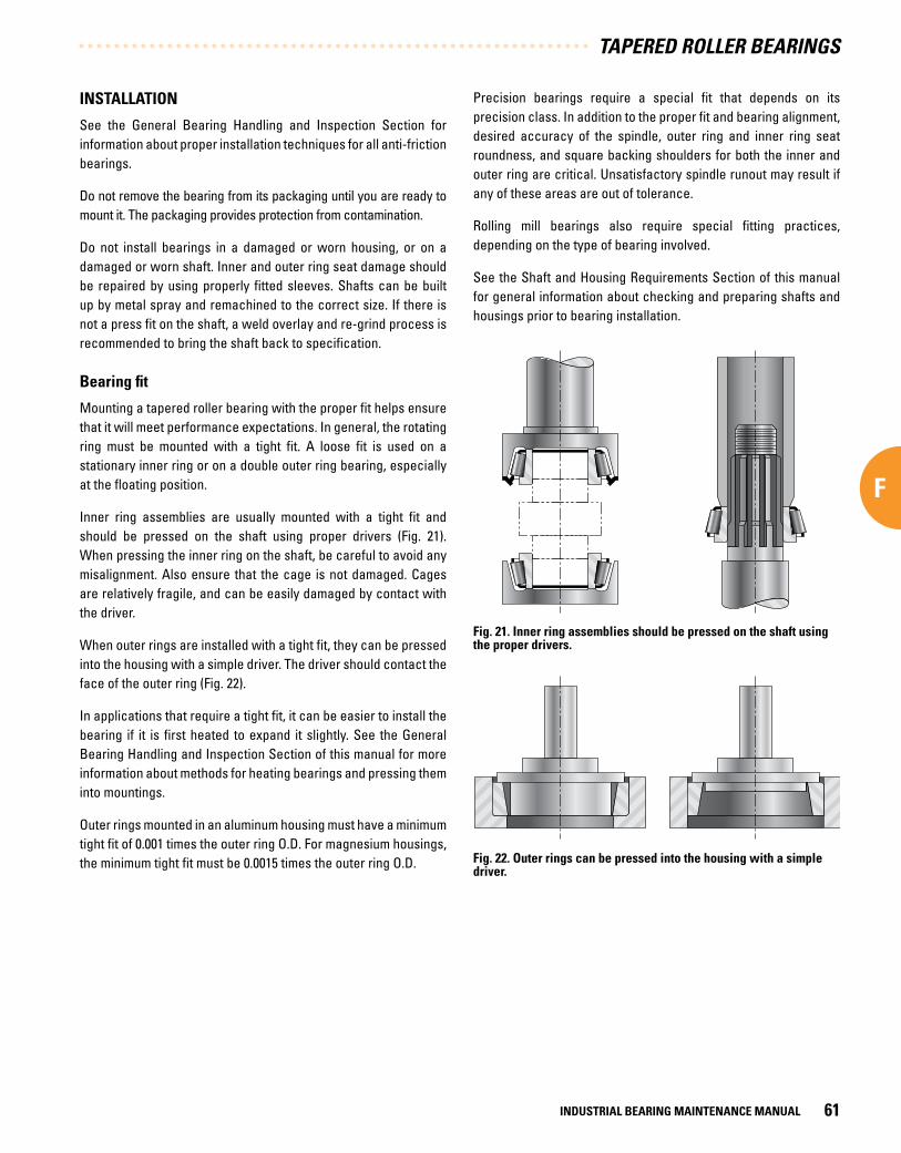
INSTALLATION
See the General Bearing Handling and Inspection Section for information about proper installation techniques for all anti-friction bearings.
Do not remove the bearing from its packaging until you are ready to mount it. The packaging provides protection from contamination.
Do not install bearings in a damaged or worn housing, or on a damaged or worn shaft. Inner and outer ring seat damage should be repaired by using properly fitted sleeves. Shafts can be built up by metal spray and remachined to the correct size. If there is not a press fit on the shaft, a weld overlay and re-grind process is recommended to bring the shaft back to specification.
Bearing fit
Mounting a tapered roller bearing with the proper fit helps ensure that it will meet performance expectations. In general, the rotating ring must be mounted with a tight fit. A loose fit is used on a stationary inner ring or on a double outer ring bearing, especially at the floating position.
Inner ring assemblies are usually mounted with a tight fit and should be pressed on the shaft using proper drivers (Fig. 21). When pressing the inner ring on the shaft, be careful to avoid any misalignment. Also ensure that the cage is not damaged. Cages are relatively fragile, and can be easily damaged by contact with the driver.
When outer rings are installed with a tight fit, they can be pressed into the housing with a simple driver. The driver should contact the face of the outer ring (Fig. 22).
In applications that require a tight fit, it can be easier to install the bearing if it is first heated to expand it slightly. See the General Bearing Handling and Inspection Section of this manual for more information about methods for heating bearings and pressing them into mountings.
Outer rings mounted in an aluminum housing must have a minimum tight fit of 0.001 times the outer ring O.D. For magnesium housings, the minimum tight fit must be 0.0015 times the outer ring O.D.
Precision bearings require a special fit that depends on its precision class. In addition to the proper fit and bearing alignment, desired accuracy of the spindle, outer ring and inner ring seat roundness, and square backing shoulders for both the inner and outer ring are critical. Unsatisfactory spindle runout may result if any of these areas are out of tolerance.
Rolling mill bearings also require special fitting practices, depending on the type of bearing involved.
See the Shaft and Housing Requirements Section of this manual for general information about checking and preparing shafts and housings prior to bearing installation.
Fig . 21 . Inner ring assemblies should be pressed on the shaft using the proper drivers .
Fig . 22 . Outer rings can be pressed into the housing with a simple driver .
TAPERED ROLLER BEARINGS
INDUSTRIAL BEARING MAINTENANCE MANUAL 61
F

Tapered roller bearing adjustment techniques
One advantage of Timken tapered roller bearings is their setting can be adjusted for better performance in a given application. Some applications require a preload setting while other applications require end play. The amount of preload or end play depends on the particular application.
The proper bearing setting depends on many application requirements, including the flexibility of the housing and shaft, lubrication, speed, desired life and others. To determine the optimum bearing setting, refer to the original equipment manufacturer’s maintenance and repair literature to determine the setting used in the original application.
Methods of measuring bearing setting
When bearing preload is required, the most convenient way to determine the preload is to read the torque from the shaft’s rotation. To measure torque, wrap a string around a gear or other known diameter (Fig. 24). Attach a spring scale to the string and pull the spring scale to rotate the shaft at a slow, steady speed. Read the force indicated on the spring scale. Multiply the force times the radius to determine the bearing torque.
Fig . 23 . Bearings should be checked with a feeler gage to ensure proper fit .
Machined surface finishes for shafts and housings
The inner and outer ring seats should be smooth and within specified tolerances for size, roundness and taper. Ground finish is usually suggested for shafts whenever possible.
The suggested finish for ground and turned surfaces is:
• Inner ring seats – Ground: 1.6 Ra micrometers (65 microinches) maximum
• Inner ring seats – Turned: 3.2 Ra micrometers (125 microinches) maximum
• Outer ring seats – Turned: 3.2 Ra micrometers (125 microinches) maximum
Bearing seat finishes rougher than these limits reduce the contact area between the bearing and the seat. This can create a more loose fit, especially if the ring is pressed on and off several times.
Mounting
See the General Bearing Handling and Inspection Section for more information about mounting bearings, including methods to heat bearings or press them on/in using an arbor press.
When heating tapered roller bearings, inner ring temperatures should not exceed 120°C (250°F) for Standard Class bearings and 66°C (150°F) for Precision Class bearings. Higher temperatures can change the bearing’s hardness and geometry.
Aluminum or magnesium housed outer rings require a tight fit. To ease installation, they can be reduced in size by freezing. Standard Class bearings should not be chilled below -54°C (-65°F), and Precision Class not below -29°C (-20°F).
Whenever inner or outer rings are heated or cooled during assembly, after mounting and returning to room temperature they should be checked with a 0.001 in. - 0.002 in. feeler gage. This ensures that the inner ring is pressed tightly against the shaft shoulder (Fig. 23) or the outer ring is pressed tightly against the housing shoulder. Before checking, ensure that both the inner and outer rings are pressed tightly against the shaft or housing shoulder.
When using a press to install bearings, avoid damage to the inner ring assembly. Tapered roller bearings should be separated (the inner ring assembly removed from the outer ring) during installation. When installing the inner ring assembly, use great care to ensure that no force is applied to the cage or rolling elements.
TAPERED ROLLER BEARINGS
INDUSTRIAL BEARING MAINTENANCE MANUAL62
F

You can obtain a direct torque reading by using a torque wrench (Figures 25 and 26). If necessary, you can convert torque into preload force or dimensional preload. For assistance, contact your Timken representative.
Fig . 25 . Standard torque wrench .
Fig . 24 . Instrument to measure torque .
Bearing end play
If bearing end play is required, then a different method must be used to measure the amount of end play.
Locate a dial indicator against the end or shoulder on the shaft to measure the amount of axial movement (Fig. 27). Load the shaft in one direction and oscillate it several times while the load is applied. A handle can be mounted on the shaft to make it easier to apply the load while oscillating the shaft. Oscillate the shaft at least 20 times to firmly seat the bearings and ensure an accurate reading.
After seating the bearings in one direction, set the indicator to zero. Then apply the load in the opposite direction, oscillating the shaft as before, and read any movement on the indicator. The difference between the two readings is the end play.
Adjusting the bearing
There are two common bearing adjustment methods: threaded shaft with a nut and a housing with an outer ring follower.
If end play is desired, back off the nut until no drag is felt. If the bearings are to be preloaded, advance the nut until the required torque is measured on the shaft.
Where shims are used, the bearing is set by tightening the end cap or bearing outer ring follower without shims in place until the bearings bind slightly while rotating. The gap between the end plate and the housing is measured with a feeler gage. This gap plus the desired end play will determine the total shim pack required.
Fig . 27 . Measure axial movement by locating a dial indicator against the end of the shaft .
Fig . 26 . Electronic torque wrench .Photo courtesy of Matco Tools
TAPERED ROLLER BEARINGS
INDUSTRIAL BEARING MAINTENANCE MANUAL 63
F

SHIM PACK FIXTURES
Fixtures for determining the required amount of shims may be appropriate in high-production facilities where bearings are frequently adjusted. For most facilities, a simple fixture can be used to check the distance from the outer ring back face to the housing face. Compare this dimension to the outer ring follower in another fixture (Fig. 28). The difference between these dimensions determines the amount of shim pack, and takes into consideration the amount of end play or preload required for the application.
Determining cone spacer length TDO type
Some applications require a spacer between the two inner rings to obtain proper bearing adjustment. A simplified method of measuring the inner ring spacer length for a tapered double outer (TDO) bearing is described below. This method will result in an accurate measurement of dimension “B,” which is the nominal width of the spacer.
Before beginning the measurement process, mark the “A” and “C” sides of the components as shown in Fig. 29. For proper measurement, it is important that the “A” inner ring is placed in the “A” side of the outer ring, and the “C” inner ring is placed in the “C” side of the outer ring.
The formula to calculate the “B” dimension is:
B = (AB + CB) – AC
Where:
B = Distance between cone front faces
AB = Distance between C cone front face and A cup face
CB = Distance between A cone front face and C cup face
AC = Cup length
Procedure
Place inner ring “C” with the back face (larger surface) down on a surface plate, and place the outer ring with the “C” face down on top of the inner race (Fig.29). Oscillate the outer race under load to seat the rollers firmly against the rib. Measure the AB distance (drop) using a depth micrometer or a dial indicator. Take measurements at four locations around the outer ring, at 12 o’clock, 3 o’clock, 6 o’clock and 9 o’clock and average them to get the average AB drop. Taking multiple readings provides greater accuracy and compensates for the possibility of a slightly misaligned outer ring.
Place inner ring “A” back face down on the surface plate. Move the outer ring, inverting it so the outer ring has side “A” down, and place it on inner ring “A.” Oscillate the outer ring under load and measure the CB drop at four locations. Average these measurements to calculate the CB drop.
Use a parallel bar when measuring AB and CB, and be careful not to rotate the outer ring between measurements.
Measure the width of the outer ring at four locations and average them to determine the AC distance.
Calculate the B dimension. Add the desired end play amount, or subtract the desired preload. The resulting figure is the nominal spacer width needed to obtain the desired bearing setting. Grind the spacer to the nominal amount.
Clamp bolt
Outer ring follower
A
B
Dial indicator
Fig . 28 . Shim pack comparison .
TAPERED ROLLER BEARINGS
INDUSTRIAL BEARING MAINTENANCE MANUAL64
F

Tapered roller bearings
The design of a Timken tapered roller bearing allows the setting of bearing internal clearance during installation to optimize bearing operation.
General industrial application fitting practice standards for cones and cups are shown in the following tables. These tables apply to solid or heavy-sectioned steel shafts, heavy-sectioned ferrous housings, and normal operating conditions. To use the tables, it is necessary to determine if the member is rotating or stationary, the magnitude, direction, and type of loading, and the shaft finish.
Certain table fits may not be adequate for light shaft and housing sections, shafts other than steel, nonferrous housings, critical operation conditions such as high speed, unusual thermal or loading conditions, or a combination thereof. Also, assembly procedures and the means and ease of obtaining the bearing setting may require special fits. In these cases, your Timken representative should be consulted for review and suggestions.
Rotating cones generally should be applied with an interference fit. In special cases loose fits may be considered if it has been determined by test or experience they will perform satisfactorily.
A A C
A
C
BAC
AB CB
C
C
C
A
A
Fig . 29 . Before beginning the measuring process, mark the “A” and “C” sides of the components .
The term “rotating cone” describes a condition in which the cone rotates relative to the load. This may occur with a rotating cone under a stationary load or a stationary cone with a rotating load. Loose fits will permit the cones to creep and wear the shaft and the backing shoulder. This will result in excessive bearing looseness and possible bearing and shaft damage.
FITTING PRACTICES
Stationary cone fitting practice depends on the application. Under conditions of high speed, heavy loads or shock, interference fits using heavy-duty fitting practice, should be used. With cones mounted on unground shafts subjected to moderate loads (no shock) and moderate speeds, a metal-to-metal or near zero average fit is used. In sheave and wheel applications using unground shafts, or in cases using ground shafts with moderate loads (no shock), a minimum fit near zero to a maximum looseness which varies with the cone bore size is suggested. In stationary cone applications requiring hardened and ground spindles, a slightly looser fit may be satisfactory. Special fits may also be necessary on installations such as multiple sheave crane blocks.
Rotating cup applications where the cup rotates relative to the load should always use an interference fit.
TAPERED ROLLER BEARINGS
INDUSTRIAL BEARING MAINTENANCE MANUAL 65
F

Stationary, nonadjustable and fixed single-row cup applications should be applied with a tight fit wherever practical. Generally, adjustable fits may be used where the bearing setup is obtained by sliding the cup axially in the housing bore. However, in certain heavy-duty, high-load applications, tight fits are necessary to prevent pounding and plastic deformation of the housing. Tightly fitted cups mounted in carriers can be used. Tight fits are suggested when the load rotates relative to the cup.
To permit through-boring when the outside diameters of single-row bearings mounted at each end of a shaft are equal and one is adjustable and the other fixed, it is suggested that the same adjustable fit be used at both ends. However, tight fits should be used if cups are backed against snap rings, to prevent excessive dishing of snap rings, groove wear and possible loss of ring retention. Only cups with a maximum housing fillet radius requirement of 1.3 mm (0.05 in.) or less should be considered for a snap ring backing.
Two-row stationary double cups are generally mounted with loose fits to permit assembly and disassembly. The loose fit also permits float when a floating bearing is mounted in conjunction with an axially fixed bearing on the other end of the shaft.
The fitting practice tables that follow have been prepared for both metric and inch dimensions.
For the inch system bearings, classes 4 and 2 (standard) and classes 3, 0, and 00 (precision) have been included.
The metric system bearings that have been included are classes K and N (metric system standard bearings) and classes C, B, and A (metric system precision bearings).
Precision class bearings should be mounted on shafts and in housings which are similarly finished to at least the same precision limits as the bearing bore and O.D. High quality surface finishes should also be provided.
Two-row and four-row bearings, which are provided with spacers and shipped as matched assemblies, have been preset to a specific bench end play. The specific end play setting is determined from a study of the bearing mounting and expected environment. It is dependent on the fitting practice and the required mounted bearing settings. Failure to use the designated fitting practice in the bearing application can result in improper bearing performance or sudden malfunction of the bearing, which may cause damage to machinery in which the bearing is a component.
For rolling mill roll neck fitting practice, consult your Timken representative. For all other equipment associated with the rolling mill industry, the fitting practice suggestions in the tables that follow should be used.
TAPERED ROLLER BEARINGS
INDUSTRIAL BEARING MAINTENANCE MANUAL66
F

THIS PAGE IS INTENTIONALLY LEFT BLANK.
TAPERED ROLLER BEARINGS
INDUSTRIAL BEARING MAINTENANCE MANUAL 67
F

Cone Bore Deviation From Minimum Cone Bore And Resultant Fit
Range(mm/in.)
Tole
ranc
e (m
m/in
.) (3
)
Rotating Cone Rotating OrStationary Cone Stationary Cone
Ground Seat Unground OrGround Seat Unground Seat Ground Seat Unground Seat Hardened And
Ground Seat
Constant Loads With Moderate Shock
Heavy Loads, OrHigh Speed Or Shock
Moderate Loads,No Shock
Moderate Loads,No Shock
Sheaves,Wheels, Idlers Wheel Spindles
Over Incl.
Cone Seat Deviation
ResultantFit
Cone Seat Deviation
ResultantFit
Cone Seat Deviation
ResultantFit
Cone Seat Deviation
ResultantFit
Cone Seat Deviation
ResultantFit
Cone Seat Deviation
ResultantFit
mmin.
mmin.
mmin.
mmin.
mmin.
mmin.
mmin.
0 .0000.0000
76 .2003.0000
0 .000+0 .0130.0000
+0.0005
+0 .038 (1)
+0 .025+0.0015+0.0010
0 .038T0 .012T0.0015T0.0005T
+0 .064+0 .038+0.0025+0.0015
0 .064T0 .025T0.0025T0.0010T
+0 .0130 .000
+0.00050.0000
0 .013T0 .013L
0.0005T0.0005L
0 .000-0 .0130.0000-0.0005
0 .0000 .026L0.00000.0010L
0 .000-0 .0130.0000-0.0005
0 .0000 .026L0.00000.0010L
-0 .005-0 .018-0.0002-0.0007
0 .005L0 .031L0.0002L0.0012L
76 .2003.0000
304 .80012.0000
0 .000+0 .0250.0000
+0.0010
+0 .064+0 .038+0.0025+0.0015
0 .064T0 .013T0.0025T0.0005T
Use Average (2)
Tight Cone Fit of0 .0005 mm/mm(0.0005 in./in.)of Cone Bore
+0 .0250 .000
+0.00100.0000
0 .025T0 .025L
0.0010T0.0010L
0 .000-0 .0250.0000-0.0010
0 .0000 .050L0.00000.0020L
0 .000-0 .0250.0000-0.0010
0 .0000 .050L0.00000.0020L
-0 .005-0 .030-0.0002-0.0012
0 .005L0 .055L0.0002L0.0022L
304 .80012.0000
609 .60024.0000
0 .000+0 .0510.0000
+0.0020
+0 .127+0 .076+0.0050+0.0030
0 .127T0 .025T0.0050T0.0010T
+0 .0510 .000
+0.00200.0000
0 .051T0 .051L
0.0020T0.0020L
0 .000-0 .0510.0000-0.0020
0 .0000 .102L0.00000.0040L
0 .000-0 .0510.0000-0.0020
0 .0000 .102L0.00000.0040L
– –
609 .60024.0000
914 .40036.0000
0 .000+0 .0760.0000
+0.0030
+0 .190+0 .114+0.0075+0.0045
0 .190T0 .038T0.0075T0.0015T
+0 .0760 .000
+0.00300.0000
0 .076T0 .076L
0.0030T0.0030L
0 .000-0 .0760.0000-0.0030
0 .0000 .152L0.00000.0060L
0 .000-0 .0760.0000-0.0030
0 .0000 .152L0.00000.0060L
– –
Class: 4 and 2 Cones
(1) Example: If the minimum cone bore is 76.200 mm (3.0000 in.), the suggested shaft size = 76.238 mm (3.0015 in.)to 76.225 mm (3.0010 in.) for a cone fit of 0.038 mm (0.0015 in.) tight to 0.012 mm (0.0005 in.) tight.
(2) For cone bores between 76.200 mm (3.0000 in.) and 101.600 mm (4.0000 in.), use a minimum fit of 0.025 mm (0.001 in.) tight.
(3) Does not apply to TNASW and TNASWE type bearings.
TAPERED ROLLER BEARINGS
INDUSTRIAL BEARING MAINTENANCE MANUAL68
F

Cup O.D. Deviation From Minimum Cup O.D. And Resultant Fit
Range(mm/in.)
Tole
ranc
e (m
m/in
.) Stationary Cup Stationary Or Rotating Cup Rotating Cup
Floating Or Clamped Adjustable Non Adjustable Or In Carriers,Sheaves - Clamped Sheaves - Unclamped (1)
Over Incl.
Cup Seat Deviation Resultant Fit Cup Seat
Deviation Resultant Fit Cup Seat Deviation Resultant Fit Cup Seat
Deviation Resultant Fit
mmin.
mmin.
mmin.
mmin.
mmin.
0 .0000.0000
76 .2003.0000
+0 .0250 .000
+0.00100.0000
+0 .051+0 .076+0.0020+0.0030
0 .026L0 .076L0.0010L0.0030L
0 .000+0 .0250.0000
+0.0010
0 .025T0 .025L
0.0010T0.0010L
-0 .038-0 .013-0.0015-0.0005
0 .063T0 .013T0.0025T0.0005T
-0 .076-0 .051-0.0030-0.0020
0 .101T0 .051T0.0040T0.0020T
76 .2003.0000
127 .0005.0000
+0 .0250 .000
+0.00100.0000
+0 .051+0 .076+0.0020+0.0030
0 .026L0 .076L0.0010L0.0030L
0 .000+0 .0250.0000
+0.0010
0 .025T0 .025L
0.0010T0.0010L
-0 .051-0 .025-0.0020-0.0010
0 .076T0 .025T0.0030T0.0010T
-0 .076-0 .051-0.0030-0.0020
0 .101T0 .051T0.0040T0.0020T
127 .0005.0000
304 .80012.0000
+0 .0250 .000
+0.00100.0000
+0 .051+0076
+0.0020+0.0030
0 .026L0 .076L0.0010L0.0030L
0 .000+0 .0510.0000
+0.0020
0 .025T0 .051L
0.0010T0.0020L
-0 .051-0 .025-0.0020-0.0010
0 .076T0 .025T0.0030T0.0010T
-0 .076-0 .051-0.0030-0.0020
0 .101T0 .051T0.0040T0.0020T
304 .80012.0000
609 .60024.0000
+0 .0510 .000
+0.00200.0000
+0 .102+0 .152+0.0040+0.0060
0 .051L0 .152L0.0020L0.0060L
+0 .026+0 .076+0.0010+0.0030
0 .025T0 .076L
0.0010T0.0030L
-0 .076-0 .025-0.0030-0.0010
0 .127T0 .025T0.0050T0.0010T
-0102-0 .051-0.0040-0.0020
0 .153T0 .051T0.0060T0.0020T
609 .60024.0000
914 .40036.0000
+0 .0760 .000
+0.00300.0000
+0 .152+0 .229+0.0060+0.0090
0 .076L0 .229L0.0030L0.0090L
+0 .051+0 .127+0.0020+0.0050
0 .025T0 .127L
0.0010T0.0050L
-0 .102-0 .025-0.0040-0.0010
0 .178T0 .025T0.0070T0.0010T
– –
Class: 4 and 2 Cups
(1) Unclamped cup design is applicable only to sheaves with negligible fleet angle.
TAPERED ROLLER BEARINGS
INDUSTRIAL BEARING MAINTENANCE MANUAL 69
F

Cone Bore Deviation From Minimum Cone Bore And Resultant Fit
Range(mm/in.)
Tole
ranc
e (m
m/in
.)
Rotating Cone Stationary Cone
Ground Seat Ground Seat Ground Seat
Precision Machine Tool SpindlesHeavy Loads,
Or High SpeedOr Shock
Precision Machine Tool Spindles
Over Incl.
Cone Seat Deviation Resultant Fit Cone Seat Deviation Resultant Fit
mmin.
mmin.
mmin.
0 .0000.0000
304 .80012.0000
0 .000+0 .0130.0000
+0.0005
+0 .030+0 .018+0.0012+0.0007
0 .030T0 .005T0.0012T0.0002T
Use MinimumTight Cone Fit of0 .00025 mm/mm(0.00025 in./in.)of Cone Bore
+0 .030+0 .018+0.0012+0.0007
0 .030T0 .005T0.0012T0.0002T
304 .80012.0000
609 .60024.0000
0 .000+0 .0250.0000
+0.0010
+0 .064+0 .038+0.0025+0.0015
0 .064T0 .013T0.0025T0.0005T
+0 .064+0 .038+0.0025+0.0015
0 .064T0 .013T0.0025T0.0005T
609 .60024.0000
914 .40036.0000
0 .000+0 .0380.0000
+0.0015
+0 .102+0 .064+0.0040+0.0025
0 .102T0 .026T0.0040T0.0010T
+0 .102+0 .064+0.0040+0.0025
0 .102T0 .025T0.0040T0.0010T
Class: 3 and 0 (1) Cones
(1) Maximum cone bore for Class 0 Product is 241.300 mm (9.5000 in.).
TAPERED ROLLER BEARINGS
INDUSTRIAL BEARING MAINTENANCE MANUAL70
F

Cup O.D. Deviation From Minimum Cup O.D. And Resultant Fit
Range(mm/in.)
Tole
ranc
e (m
m/in
.) Stationary Cup Rotating Cup
Floating Clamped Adjustable NonadjustableOr In Carriers
NonadjustableOr In Carriers
Over Incl.
Cup Seat Deviation Resultant Fit Cup Seat
Deviation Resultant Fit Cup Seat Deviation Resultant Fit Cup Seat
Deviation Resultant Fit Cup Seat Deviation Resultant Fit
mmin.
mmin.
mmin.
mmin.
mmin.
mmin.
0 .0000.0000
152 .4006.0000
+0 .0130 .000
+0.00050.0000
+0 .025+0 .038+0.0010+0.0015
0 .012L0 .038L0.0005L0.0015L
+0 .013+0 .025+0.0005+0.0010
0 .0000 .025L0.00000.0010L
0 .000+0 .0130.0000
+0.0005
0 .013T0 .013L
0.0005T0.0005L
-0 .0130 .000
-0.00050.0000
0 .026T0 .000
0.0010T0.0000
-0 .025-0 .013-0.0010 -0.0005
0 .038T0 .013T0.0015T0.0005T
152 .4006.0000
304 .80012.0000
+0 .0130 .000
+0.00050.0000
+0 .025+0 .038+0.0010+0.0015
0 .012L0 .038L0.0005L0.0015L
+0 .013+0 .025+0.0005+0.0010
0 .0000 .025L0.00000.0010L
0 .000+0 .0250.0000
+0.0010
0 .013T0 .025L
0.0005T0.0010L
-0 .0250 .000-0.0010.0000
0 .038T0 .000
0.0015T0.0000
-0 .038-0 .013-0.0015-0.0005
0 .051T0 .013T0.0020T0.0005T
304 .80012.0000
609 .60024.0000
+0 .0250 .000
+0.00100.0000
+0 .038+0 .064+0.0015+0.0025
0 .013L0 .064L0.0005L0.0025L
+0 .025+0 .051+0.0010+0.0020
0 .0000 .051L0.00000.0020L
0 .000+0 .0250.0000
+0.0010
0 .025T0 .025L
0.0010T0.0010L
-0 .0250 .000-0.0010.0000
0 .050T0 .000
0.0020T0.0000
-0 .038-0 .013-0.0015-0.0005
0 .063T0 .013T0.0025T0.0005T
609 .60024.0000
914 .40036.0000
+0 .0380 .000
+0.00150.0000
+0 .051+0 .089+0.0020+0.0035
0 .013L0 .089L0.0005L0.0035L
+0 .038+0 .076+0.0015+0.0030
0 .0000 .076L0.00000.0030L
0 .000+0 .0380.0000
+0.0015
0 .038T0 .038L
0.0015T0.0015L
-0 .0380 .000
-0.00150.0000
0 .076T0 .000
0.0030T0.0000
-0 .051-0 .013-0.0020-0.0005
0 .089T0 .013T0.0035T0.0005T
Class: 3 and 0 (1) Cups
(1) Maximum cup O.D. for Class 0 product is 315.000 mm (12.4016 in.).
TAPERED ROLLER BEARINGS
INDUSTRIAL BEARING MAINTENANCE MANUAL 71
F

Cone Bore Deviation From Minimum Cone Bore And Resultant Fit
Range(mm/in.)
Tolerance(mm/in.)
Rotating Cone Stationary Cone
Ground Seat Ground Seat
Precision Machine Tool Spindles Precision Machine Tool Spindles
Over Incl.
Cone Seat Deviation Resultant Fit Cone Seat Deviation Resultant Fit
mmin.
mmin.
mmin.
0 .0000.0000
315 .00012.4016
0 .000+0 .0080.0000
+0.0003
+0 .020+0 .013+0.0008+0.0005
0 .020T0 .005T0.0008T0.0002T
+0 .020+0 .013+0.0008+0.0005
0 .020T0 .005T0.0008T0.0002T
Class: 00 and 000 Cones
Cup O.D. Deviation From Minimum Cup O.D. And Resultant Fit
Range(mm/in.)
Tole
ranc
e (m
m/in
.) Stationary Cup Rotating Cup
Floating Clamped Adjustable NonadjustableOr In Carriers
NonadjustableOr In Carriers
Over Incl.
Cup Seat Deviation Resultant Fit Cup Seat
Deviation Resultant Fit Cup Seat Deviation Resultant Fit Cup Seat
Deviation Resultant Fit Cup Seat Deviation Resultant Fit
mmin.
mmin.
mmin.
mmin.
mmin.
mmin.
0 .0000.0000
315 .00012.4016
+0 .0080 .000
+0.00030.0000
+0 .015+0 .023+0.0006+0.0009
0 .007L0 .023L0.0003L0.0009L
+0 .008+0 .015+0.0003+0.0006
0 .0000 .015L0.00000.0006L
0 .000+0 .0080.0000
+0.0003
0 .008T0 .008L
0.0003T0.0003L
-0 .0080 .000
-0.00030.0000
0 .016T0 .000
0.0006T0.0000
-0 .015-0 .008-0.0006 -0.0003
0 .023T0 .008T0.0009T0.0003T
Class: 00 and 000 Cups
TAPERED ROLLER BEARINGS
INDUSTRIAL BEARING MAINTENANCE MANUAL72
F

THIS PAGE IS INTENTIONALLY LEFT BLANK.
TAPERED ROLLER BEARINGS
INDUSTRIAL BEARING MAINTENANCE MANUAL 73
F

Cone Bore Deviation From Maximum Cone Bore And Resultant Fit
Range(mm/in.)
Tolerance (mm/in.)
Rotating Cone Rotating Or Stationary Cone Stationary Cone
Ground Seat Unground Seat Or Ground Seat Unground Seat
Constant Loads With Moderate Shock Heavy Loads, High Speed Or Shock Moderate Loads, No Shock
Over Incl.
Cone Seat Deviation
ResultantFit Symbol Cone Seat
DeviationResultant
Fit Symbol Cone Seat Deviation
Resultant Fit Symbol
mmin.
mmin.
mmin.
mmin.
10 .0000.3937
18 .0000.7087
-0 .0120 .000
-0.00050.0000
+0 .018+0 .007+0.0007+0.0003
0 .030T0 .007T0.0012T0.0003T
m6
+0 .023+0 .013+0.0009+0.0005
0 .035T0 .013T0.0014T0.0005T
n6
0 .000-0 .0100.0000-0.0004
0 .012T0 .010L
0.0005T0.0004L
h6
18 .0000.7087
30 .0001.1811
-0 .0120 .000
-0.00050.0000
+0 .021+0 .008+0.0008+0.0003
0 .033T0 .008T0.0013T0.0003T
m6
+0 .028+0 .015+0.0011+0.0006
0 .040T0 .015T0.0016T0.0006T
n6
0 .000-0 .0130.0000-0.0005
0 .012T0 .013L
0.0005T0.0005L
h6
30 .0001.1811
50 .0001.9685
-0 .0120 .000
-0.00050.0000
+0 .025+0 .009+0.0010+0.0004
0 .037T0 .009T0.0015T0.0004T
m6
+0 .033+0 .017+0.0013+0.0007
0 .045T0 .017T0.0018T0.0007T
n6
0 .000-0 .0160.0000-0.0006
0 .012T0 .016L
0.0005T0.0006L
h6
50 .0001.9685
80 .0003.1496
-0 .0150 .000
-0.00060.0000
+0 .030+0 .011+0.0012+0.0005
0 .045T0 .011T0.0018T0.0005T
m6
+0 .039+0 .020+0.0015+0.0008
0 .053T0 .020T0.0021T0.0008T
n6
0 .000-0 .0190.0000-0.0007
0 .015T0 .019L
0.0006T0.0007L
h6
80 .0003.1496
120 .0004.7244
-0 .0200 .000
-0.00080.0000
+0 .035+0 .013+0.0014+0.0005
0 .055T0 .013T0.0022T0.0005T
m6
+0 .045+0 .023+0.0019+0.0010
0 .065T0 .023T0.0027T0.0010T
n6
0 .000-0 .0220.0000-0.0009
0 .020T0 .022L
0.0008T0.0009L
h6
120 .0004.7244
180 .0007.0866
-0 .0250 .000
-0.00100.0000
+0 .052+0 .027+0.0022+0.0012
0 .077T0 .027T0.0032T0.0012T
n6
+0 .068+0 .043+0.0028+0.0018
0 .093T0 .043T0.0038T0.0018T
p6
0 .000-0 .0250.0000-0.0010
0 .025T0 .025L
0.0010T0.0010L
h6
180 .0007.0866
200 .0007.8740
-0 .030 0 .000
-0.00120.0000
+0 .060 +0 .031+0.0026+0.0014
0 .090T 0 .031T0.0038T0.0014T
n6
+0 .106+0 .077+0.0042+0.0030
0 .136T0 .077T0.0054T0.0030T
r6
0 .000-0 .0290.0000-0.0012
0 .030T 0 .029L
0.0012T0.0012L
h6200 .0007.8740
225 .0008.8583
+0 .109+0 .080+0.0043+0.0031
0 .139T0 .080T0.0055T0.0031T
225 .0008.8583
250 .0009.8425
+0 .113+0 .084+0.0044+0.0033
0 .143T0 .084T0.0056T0.0033T
Class: K and N Cones
TAPERED ROLLER BEARINGS
INDUSTRIAL BEARING MAINTENANCE MANUAL74
F

Deviation From Maximum Cone Bore And Resultant Fit
Stationary Cone
Ground Seat Unground Seat Hardened And Ground Seat
Moderate Loads, No Shock Sheaves, Wheels, Idlers Wheel Spindles
Cone Seat Deviation
ResultantFit Symbol Cone Seat
DeviationResultant
Fit Symbol Cone Seat Deviation
ResultantFit Symbol
mmin.
mmin.
mmin.
-0 .006-0 .017
-0.00025-0.00065
0 .006T0 .017L
0.00025T0.00065L
g6
-0 .006-0 .017
-0.00025-0.00065
0 .006T0 .017L
0.00025T0.00065L
g6
-0 .016-0 .027-0.0006-0.0010
0 .004L0 .027L0.0001L 0.0010L
f6
-0 .007-0 .020
-0.0003-0.0008
0 .005T0 .020L
0.0002T0.0008L
g6
-0 .007-0 .020-0.0003-0.0008
0 .005T0 .020L
0.0002T0.0008L
g6
-0 .020-0 .033-0.0008-0.0013
0 .008L0 .033L0.0003L 0.0013L
f6
-0 .009-0 .025
-0.0004-0.0010
0 .003T0 .025L
0.0001T0.0010L
g6
-0 .009-0 .025-0.0004-0.0010
0 .003T0 .025L
0.0001T0.0010L
g6
-0 .025-0 .041-0.0010-0.0016
0 .013L0 .041L0.0005L0.0016L
f6
-0 .010-0 .029
-0.0004-0.0011
0 .005T0 .029L
0.0002T0.0011L
g6
-0 .010-0 .029-0.0004-0.0011
0 .005T0 .029L
0.0002T0.0011L
g6
-0 .030-0 .049-0.0012-0.0019
0 .015L0 .049L0.0006L 0.0019L
f6
-0 .012-0 .034
-0.0005-0.0014
0 .008T0 .034L
0.0003T0.0014L
g6
-0 .012-0 .034-0.0005-0.0014
0 .008T0 .034L
0.0003T0.0014L
g6
-0 .036-0 .058-0.0014-0.0023
0 .016L0 .058L0.0006L 0.0023L
f6
-0 .014-0 .039
-0.0006-0.0016
0 .011T0 .039L
0.0004T0.0016L
g6
-0 .014-0 .039-0.0006-0.0016
0 .011T0 .039
0.0004T0.0016L
g6
-0 .043-0 .068-0.0016-0.0026
0 .018L0 .068L0.0006L 0.0026L
f6
-0 .015 -0 .044
-0.0006-0.0018
0 .015T0 .044L
0.0006T0.0018L
g6
-0 .015-0 .044-0.0006-0.0018
0 .015T 0 .044L
0.0006T0.0018L
g6
-0 .050 -0 .079-0.0020-0.0032
0 .020L 0 .079L0.0008L 0.0032L
f6
Continued on next page.
TAPERED ROLLER BEARINGS
INDUSTRIAL BEARING MAINTENANCE MANUAL 75
F

Cone Bore Deviation From Maximum Cone Bore And Resultant Fit
Range(mm/in.)
Tolerance (mm/in.)
Rotating Cone Rotating Or Stationary Cone Stationary Cone
Ground Seat Unground Seat Or Ground Seat Unground Seat
Constant Loads With Moderate Shock Heavy Loads, High Speed Or Shock Moderate Loads, No Shock
Over Incl.
Cone Seat Deviation
ResultantFit Symbol Cone Seat
DeviationResultant
Fit Symbol Cone Seat Deviation
Resultant Fit Symbol
mmin.
mmin.
mmin.
mmin.
250 .0009.8425
280 .00011.0236
-0 .035 0 .000
-0.00140.0000
+0 .066 +0 .034+0.0026+0.0014
0 .101T 0 .034T0.0040T0.0014T
n6
+0 .146+0 .094+0.0057+0.0037
0 .181T0 .094T0.0071T0.0037T
r7
0 .000-0 .0320.0000-0.0012
0 .035T 0 .032L
0.0014T0.0012L
h6
280 .00011.0236
315 .00012.4016
+0 .150+0 .098+0.0059+0.0039
0 .185T0 .098T0.0073T0.0039T
315 .00012.4016
355 .00013.9764
-0 .040 0 .000
-0.00160.0000
+0 .073+0 .037+0.0030+0.0016
0 .113T 0 .037T0.0046T0.0016T
n6
+0 .165+0 .108+0.0065+0.0043
0 .205T0 .108T0.0081T0.0043T
r7
0 .000-0 .0360.0000-0.0014
0 .040T 0 .036L
0.0016T0.0014L
h6
355 .00013.9764
400 .00015.7480
+0 .171+0 .114+0.0067+0.0045
0 .211T0 .114T0.0083T0.0045T
400 .00015.7480
450 .00017.7165
-0 .045 0 .000
-0.00180.0000
+0 .080 +0 .040+0.0034+0.0018
0 .0125T 0 .040T0.0052T0.0018T
n6
+0 .189+0 .126+0.0074+0.0050
0 .234T0 .126T0.0092T0.0050T
r7
0 .000-0 .0400.0000-0.0016
0 .045T 0 .040L
0.0018T0.0016L
h6
450 .00017.7165
500 .00019.6850
+0 .195+0 .132+0.0077+0.0052
0 .240T0 .132T0.0094T0.0052T
500 .00019.6850
630 .00024.8032
-0 .0500 .000
-0.00200.0000
+0 .100+0 .050+0.0039+0.0020
0 .150T0 .050T0.0059T0.0020T
–
+0 .200+0 .125+0.0079+0.0050
0 .250T0 .125T0.0099T0.0050T
–
0 .000-0 .0500.0000-0.0020
0 .050T0 .050L
0.0020T0.0020L
–
630 .00024.8032
800 .00031.4961
-0 .0800 .000
-0.00310.0000
+0 .125+0 .050+0.0049+0.0020
0 .205T0 .050T0.0080T0.0020T
–
+0 .225+0 .150+0.0089+0.0059
0 .305T0 .150T0.0120T0.0059T
–
0 .000-0 .0750.0000-0.0030
0 .080T0 .075L
0.0031T0.0030L
–
800 .00031.4961
1000 .00039.3701
-0 .1000 .000
-0.00390.0000
+0 .150+0 .050+0.0059+0.0020
0 .250T0 .050T0.0098T0.0020T
–
+0 .275+0 .175+0.0108+0.0069
0 .375T0 .175T0.0147T0.0069T
–
0 .000-0 .1000.0000-0.0039
0 .100T0 .100L
0.0039T0.0039L
–
Class: K and N Cones
TAPERED ROLLER BEARINGS
INDUSTRIAL BEARING MAINTENANCE MANUAL76
F

Deviation From Maximum Cone Bore And Resultant Fit
Stationary Cone
Ground Seat Unground Seat Hardened And Ground Seat
Moderate Loads, No Shock Sheaves, Wheels, Idlers Wheel Spindles
Cone Seat Deviation
ResultantFit Symbol Cone Seat
DeviationResultant
Fit Symbol Cone Seat Deviation
ResultantFit Symbol
mmin.
mmin.
mmin.
-0 .017-0 .049
-0.0007-0.0019
0 .018T 0 .049L
0.0007T0.0019L
g6
-0 .017 -0 .049-0.0007-0.0019
0 .018T 0 .049L
0.0007T0.0019L
g6
-0 .056-0 .088-0.0022-0.0034
0 .021L 0 .088L0.0008L0.0034L
f6
-0 .018-0 .075
-0.0007-0.0029
0 .022T 0 .075L
0.0009T0.0029L
g7
-0 .018-0 .075-0.0007-0.0029
0 .022T 0 .075L
0.0009T0.0029L
g7 – – –
-0 .020 -0 .083
-0.0008-0.0033
0 .025T0 .083L
0.0010T0.0033L
g7
-0 .020-0 .083-0.0008-0.0033
0 .025T 0 .083L
0.0010T0.0033L
g7 – – –
-0 .050-0 .100
-0.0020-0.0039
0 .0000 .100L0.0000
0.0039L
–
-0 .050-0 .100-0.0020-0.0039
0 .0000 .100L0.00000.0039L
– – – –
-0 .080-0 .150
-0.0031-0.0059
0 .0000 .150L0.0000
0.0059L
–
-0 .080-0 .150-0.0031-0.0059
0 .0000 .150L0.00000.0059L
– – – –
-0 .100-0 .200
-0.0039-0.0079
0 .0000 .200L0.0000
0.0079L
–
-0 .100-0 .200-0.0039-0.0079
0 .0000 .200L0.00000.0079L
– – – –
TAPERED ROLLER BEARINGS
INDUSTRIAL BEARING MAINTENANCE MANUAL 77
F

Class: K and N Cups
Cup O.D. Deviation From Maximum Cup O.D. And Resultant Fit
Range(mm/in.)
Tolerance (mm/in.)
Stationary Cup Rotating Cup
Floating Or Clamped Adjustable Nonadjustable Or In Carriers Nonadjustable Or In Carriers Or Sheaves-clamped
Over Incl.
Cup Seat Deviation
ResultantFit Symbol Cup Seat
DeviationResultant
Fit Symbol Cup Seat Deviation
ResultantFit Symbol Cup Seat
DeviationResultant
Fit Symbol
mmin.
mmin.
mmin.
mmin.
mmin.
18 .0000.7087
30 .0001.1811
0 .000-0 .0120.0000-0.0005
+0 .007+0 .028+0.0003+0.0011
0 .007L0 .040L0.0003L0.0016L
G7
-0 .009+0 .012-0.0003+0.0005
0 .009T0 .024L
0.0003T0.0010L
J7
-0 .035-0 .014-0.0013-0.0005
0 .035T0 .002T0.0013T0.0000
P7
-0 .041-0 .020-0.0017-0.0009
0 .041T0 .008T0.0017T0.0004T
R7
30 .000 1.1811
50 .0001.9685
0 .000-0 .0140.0000-0.0006
+0 .009+0 .034+0.0004+0.0014
0 .009L0 .048L0.0004L0.0020L
G7
-0 .011+0 .014-0.0004+0.0006
0 .011T0 .028L
0.0004T0.0011L
J7
-0 .042-0 .017-0.0016-0.0006
0 .042T0 .003T0.0016T0.0000
P7
-0 .050-0 .025-0.0020-0.0010
0 .050T0 .011T0.0020T0.0004T
R7
50 .0001.9685
65 .0002.5591
0 .000-0 .0160.0000-0.0006
+0 .010 +0 .040
+0.0004+0.0016
0 .010L 0 .056L
0.0004L0.0022L
G7
-0 .012 +0 .018-0.0004 +0.0008
0 .012T 0 .034L
0.0004T 0.0014L
J7
-0 .051 -0 .021-0.0021 -0.0009
0 .051T0 .005T0.0021T 0.0003T
P7
-0 .060-0 .030-0.0024 -0.0012
0 .060T0 .014T0.0024T 0.0006T
R7
65 .0002.5591
80 .0003.1496
-0 .062-0 .032-0.0024 -0.0013
0 .062T0 .016T0.0024T 0.0006T
80 .0003.1496
100 .0003.9370
0 .000-0 .0180.0000-0.0007
+0 .012 +0 .047+0.0005 +0.0019
0 .012L 0 .065L0.0005L 0.0026L
G7
-0 .013 +0 .022-0.0005 +0.0009
0 .013T 0 .040L
0.0005T 0.0016L
J7
-0 .059 -0 .024-0.0025 -0.0011
0 .059T0 .006T0.0025T 0.0004T
P7
-0 .073-0 .038-0.0029 -0.0015
0 .073T0 .020T0.0029T0.0008T
R7
100 .0003.9370
120 .0004.7244
-0 .076-0 .041-0.0030 -0.0016
0 .076T0 .023T-0.0030 -0.0009
120 .000 4.7244
150 .0005.9055
0 .000-0 .0200.0000-0.0008
+0 .014+0 .054+0.0006+0.0022
0 .014L0 .074L0.0006L0.0030L
G7
-0 .014+0 .026-0.0006+0.0010
0 .014T0 .046L
0.0006T0.0018L
J7
-0 .068-0 .028-0.0028-0.0012
0 .068T0 .008T0.0028T0.0004T
P7
-0 .089-0 .048-0.0035-0.0019
0 .089T0 .028T0.0035T0.0011T
–
150 .000 5.9055
180 .0007.0866
0 .000-0 .0250.0000-0.0010
+0 .014+0 .054+0.0006+0.0022
0 .014L0 .079L0.0006L0.0032L
G7
-0 .014+0 .026-0.0006+0.0010
0 .014T0 .051L
0.0006T0.0020L
J7
-0 .068-0 .028-0.0028-0.0012
0 .068T0 .008T0.0028T0.0002T
P7
-0 .089-0 .048-0.0035-0.0019
0 .089T0 .023T0.0035T0.0009T
–
180 .0007.0866
200 .0007.8740
0 .000 -0 .0300.0000-0.0012
+0 .015 +0 .061+0.0006+0.0024
0 .015L 0 .091L0.0006L0.0036L
G7
-0 .016 +0 .030-0.0007+0.0011
0 .016T 0 .060L
0.0007T0.0023L
J7
-0 .079 -0 .033-0.0032-0.0014
0 .079T0 .003T0.0032T0.0002T
P7
-0 .106-0 .060-0.0042-0.0024
0 .106T0 .030T0.0042T0.0012T
R7200 .0007.8740
225 .0008.8583
-0 .109-0 .063-0.0043-0.0025
0 .109T0 .033T0.0043T0.0013T
225 .0008.8583
250 .0009.8425
-0 .113-0 .067-0.0044-0.0026
0 .113T0 .037T 0.0044T0.0015T
Continued on next page.
TAPERED ROLLER BEARINGS
INDUSTRIAL BEARING MAINTENANCE MANUAL78
F

Cup O.D. Deviation From Maximum Cup O.D. And Resultant Fit
Range(mm/in.)
Tolerance (mm/in.)
Stationary Cup Rotating Cup
Floating Or Clamped Adjustable Nonadjustable Or In Carriers Nonadjustable Or In Carriers Or Sheaves-clamped
Over Incl.
Cup Seat Deviation
ResultantFit Symbol Cup Seat
DeviationResultant
Fit Symbol Cup Seat Deviation
ResultantFit Symbol Cup Seat
DeviationResultant
Fit Symbol
mmin.
mmin.
mmin.
mmin.
mmin.
250 .0009.8425
280 .00011.0236
0 .000-0 .0350.0000-0.0014
+0 .017 +0 .069+0.0007+0.0027
0 .017L 0 .104L0.0007L0.0041L
G7
-0 .016 +0 .036-0.0007+0.0013
0 .016T 0 .071L
0.0007T0.0027L
J7
-0 .088 -0 .036-0.0034-0.0014
0 .088T0 .001T0.0034T0.0000
P7
-0 .126-0 .074-0.0050-0.0029
0 .126T0 .039T0.0050T0.0015T
R7
280 .00011.0236
315 .00012.4016
-0 .130-0 .078-0.0051-0.0031
0 .130T0 .043T0.0051T0.0017T
315 .00012.4016
355 .00013.9764
0 .000-0 .0400.0000-0.0016
+0 .062 +0 .098+0.0025+0.0039
0 .062L 0 .138L0.0025L0.0055L
F6
-0 .018+0 .039-0.0007+0.0015
0 .018T 0 .079L
0.0007T0.0031L
J7
-0 .098-0 .041-0.0039-0.0017
0 .098T0 .001T0.0039T0.0001T
P7
-0 .144-0 .087-0.0057-0.0034
0 .144T0 .047T0.0057T0.0019T
R7
355 .00013.9764
400 .00015.7480
-0 .150-0 .093-0.0059-0.0037
0 .150T0 .053T0.0059T0.0021T
400 .00015.7480
450 .00017.7165
0 .000-0 .0450.0000-0.0018
+0 .068 +0 .095+0.0028+0.0038
0 .068L 0 .140L0.0028L0.0056L
F5
-0 .020 +0 .043-0.0009+0.0016
0 .020T 0 .088L
0.0009T0.0034L
J7
-0 .108-0 .045-0.0044-0.0019
0 .108T 0 .000T0.0044T0.0001T
P7
-0 .166-0 .103-0.0065-0.0041
0 .166T0 .058T0.0065T0.0023T
R7
450 .00017.7165
500 .00019.6850
-0 .172-0 .109-0.0068-0.0043
0 .172T0 .064T0.0068T0.0025T
500 .000 19.6850
630 .00024.8032
0 .000-0 .0500.0000-0.0020
+0 .065+0 .115+0.0026+0.0045
0 .065L0 .165L0.0026L0.0065L
–
-0 .022+0 .046-0.0009+0.0018
0 .022T0 .096L
0.0009T0.0038L
–
-0 .118-0 .050-0.0046-0.0020
0 .118T0 .000T0.0046T0.0000
–
-0 .190-0 .120-0.0070-0.0042
0 .190T0 .070T0.0070T0.0022T
–
630 .000 24.8032
800 .00031.4961
0 .000-0 .0800.0000-0.0031
+0 .075+0 .150+0.0030+0.0059
0 .075L0 .230L0.0030L0.0090L
–
-0 .025+0 .050-0.0010+0.0020
0 .025T0 .130L
0.0010T0.0051L
–
-0 .150-0 .075-0.0059-0.0030
0 .150T0 .005L
0.0059T0.0001L
– – – –
800 .000 31.4961
1000 .00039.3701
0 .000-0 .1000.0000-0.0039
+0 .075+0 .175+0.0030+0.0069
0 .075L0 .275L0.0030L0.0108L
–
-0 .025+0 .075-0.0010+0.0030
0 .025T0 .175L
0.0010T0.0069L
–
-0 .200-0 .100-0.0079-0.0039
0 .200T0 .000T0.0079T0.0000
– – – –
TAPERED ROLLER BEARINGS
INDUSTRIAL BEARING MAINTENANCE MANUAL 79
F

Cone Bore Deviation From Maximum Cone Bore And Resultant Fit
Range(mm/in.)
Tole
ranc
e (m
m/in
.)
Rotating Cone Stationary Cone
Ground Seat Ground Seat Ground Seat
Precision Machine Tool Spindles Heavy Loads, Or High Speed Or Shock Precision Machine Tool Spindles
Over Incl.
Cone Seat Deviation Resultant Fit Symbol Cone Seat
Deviation Resultant Fit Symbol Cone Seat Deviation Resultant Fit Symbol
mmin.
mmin.
mmin.
mmin.
10 .0000.3937
18 .0000.7087
-0 .0070 .000
-0.00030.0000
+0 .009+0 .001+0.0004+0.0001
0 .016T0 .001T0.0007T0.0001T
k5
+0 .018+0 .007+0.0007+0.0003
0 .025T0 .007T0.0010T0.0003T
m6
+0 .009+0 .001+0.0004+0.0001
0 .016T0 .001T0.0007T0.0001T
k5
18 .0000.7087
30 .0001.1811
-0 .0080 .000
-0.00030.0000
+0 .011+0 .002+0.0005+0.0001
0 .019T0 .002T0.0008T0.0001T
k5
+0 .017+0 .008+0.0007+0.0003
0 .025T0 .008T0.0010T0.0003T
m5
+0 .011+0 .002+0.0005+0.0001
0 .019T0 .002T0.0008T0.0001T
k5
30 .0001.1811
50 .0001.9685
-0 .0100 .000
-0.00040.0000
+0 .013+0 .002+0.0005+0.0001
0 .023T0 .002T0.0009T0.0001T
k5
+0 .020+0 .009+0.0008+0.0004
0 .030T0 .009T0.0012T0.0004T
m5
+0 .013+0 .002+0.0005+0.0001
0 .023T0 .002T0.0009T0.0001T
k5
50 .0001.9685
80 .0003.1496
-0 .0120 .000
-0.00050.0000
+0 .015+0 .002+0.0006+0.0001
0 .027T0 .002T0.0011T0.0001T
k5
+0 .033+0 .020+0.0013+0.0008
0 .045T0 .020T0.0018T0.0008T
n5
+0 .015+0 .002+0.0006+0.0001
0 .027T0 .002T0.0011T0.0001T
k5
80 .0003.1496
120 .0004.7244
-0 .0150 .000
-0.00060.0000
+0 .018+0 .003+0.0007+0.0001
0 .033T0 .003T0.0013T0.0001T
k5
+0 .038+0 .023+0.0016+0.0010
0 .053T0 .023T0.0022T0.0010T
n5
+0 .018+0 .003+0.0007+0.0001
0 .033T0 .003T0.0013T0.0001T
k5
120 .0004.7244
180 .0007.0866
-0 .0180 .000
-0.00070.0000
+0 .021+0 .003+0.0008+0.0001
0 .039T0 .003T0.0015T0.0001T
k5
+0 .055+0 .043+0.0023+0.0018
0 .073T0 .043T0.0030T0.0018T
p4
+0 .021+0 .003+0.0008+0.0001
0 .039T0 .003T0.0015T0.0001T
k5
180 .0007.0866
200 .0007.8740
-0 .022 0 .000
-0.00090.0000
+0 .024+0 .004+0.0010+0.0002
0 .046T 0 .004T0.0019T0.0002T
k5
+0 .091+0 .077+0.0036+0.0030
0 .113T0 .077T+0.0044+0.0030
r4
+0 .024 +0 .004+0.0010+0.0002
0 .046T 0 .004T0.0019T0.0002T
k5200 .0007.8740
225 .0008.8583
+0 .094+0 .080+0.0037+0.0031
0 .116T0 .080T+0.0046+0.0031
225 .0008.8583
250 .0009.8425
+0 .098+0 .084+0.0039+0.0033
0 .120T0 .084T+0.0047+0.0033
Class: C Cones
Continued on next page.
TAPERED ROLLER BEARINGS
INDUSTRIAL BEARING MAINTENANCE MANUAL80
F

Cone Bore Deviation From Maximum Cone Bore And Resultant Fit
Range(mm/in.)
Tole
ranc
e (m
m/in
.)
Rotating Cone Stationary Cone
Ground Seat Ground Seat Ground Seat
Precision Machine Tool Spindles Heavy Loads, Or High Speed Or Shock Precision Machine Tool Spindles
Over Incl.
Cone Seat Deviation Resultant Fit Symbol Cone Seat
Deviation Resultant Fit Symbol Cone Seat Deviation Resultant Fit Symbol
mmin.
mmin.
mmin.
mmin.
250 .0009.8425
280 .00011.0236
-0 .0220 .000
-0.00090.0000
+0 .027 +0 .004+0.0011+0.0002
0 .049T 0 .004T0.0020T0.0002T
k5
-0 .126-0 .074-0.0050-0.0029
0 .126T0 .039T0.0050T0.0015T
r5
+0 .027 +0 .004+0.0011+0.0002
0 .049T 0 .004T0.0020T0.0002T
k5
280 .00011.0236
315 .00012.4016
-0 .130-0 .078-0.0051-0.0031
0 .130T0 .043T0.0051T0.0017T
315 .00012.4016
355 .00013.9764
-0 .025 0 .000
-0.00100.0000
+0 .029 +0 .004+0.0012+0.0002
0 .054T 0 .004T0.0022T0.0002T
k5
-0 .144-0 .087-0.0057-0.0034
0 .144T0 .047T0.0057T0.0019T
r5
+0 .029 +0 .004+0.0012+0.0002
0 .054T 0 .004T0.0022T0.0002T
k5
355 .00013.9764
400 .00015.7480
-0 .150-0 .093-0.0059-0.0037
0 .150T0 .053T0.0059T0.0021T
400 .00015.7480
450 .00017.7165
-0 .0250 .000
-0.00100.0000
+0 .032 +0 .005+0.0012+0.0002
0 .057T 0 .005T0.0022T0.0002T
k5
-0 .166-0 .103-0.0065-0.0041
0 .166T0 .058T0.0065T0.0023T
r5
+0 .032 +0 .005+0.0012+0.0002
0 .057T 0 .005T0.0022T0.0002T
k5
450 .00017.7165
500 .00019.6850
-0 .172-0 .109-0.0068-0.0043
0 .172T0 .064T0.0068T0.0025T
500 .00019.6850
630 .00024.8032
-0 .0300 .000
-0.00120.0000
+0 .040+0 .010+0.0016+0.0004
0 .070T0 .010T0.0028T0.0004T
–
+0 .185+0 .150+0.0073+0.0059
0 .216T0 .150T0.0085T0.0059T
–
+0 .040+0 .010+0.0016+0.0004
0 .070T0 .010T0.0028T0.0004T
–
630 .00024.8032
800 .00031.4961
-0 .0400 .000
-0.00160.0000
+0 .055+0 .015+0.0022+0.0006
0 .095T0 .015T0.0038T0.0006T
–
+0 .220+0 .175+0.0087+0.0069
0 .260T0 .175T0.0103T0.0069T
–
+0 .055+0 .015+0.0022+0.0006
0 .095T0 .015T0.0038T0.0006T
–
800 .00031.4961
1000 .00039.3701
-0 .0500 .000
-0.00200.0000
+0 .065+0 .015+0.0026+0.0006
0 .115T0 .015T0.0046T0.0006T
–
+0 .255+0 .200+0.0100+0.0079
0 .305T0 .200T0.0120T0.0079T
–
+0 .065+0 .015+0.0026+0.0006
0 .115T0 .015T0.0046T0.0006T
–
TAPERED ROLLER BEARINGS
INDUSTRIAL BEARING MAINTENANCE MANUAL 81
F

Class: C Cups
Cup O.D. Deviation From Maximum Cup O.D. And Resultant Fit
Range(mm/in.)
Tole
ranc
e(m
m/in
.)Stationary Cup Rotating Cup
Floating Clamped Adjustable Nonadjustable Or In Carriers Nonadjustable Or In Carriers
Over Incl.
Cup Seat Deviation
Resultant Fit Symbol Cup Seat
DeviationResultant
Fit Symbol Cup Seat Deviation
Resultant Fit Symbol Cup Seat
DeviationResultant
Fit Symbol Cup Seat Deviation
Resultant Fit Symbol
mmin.
mmin.
mmin.
mmin.
mmin.
mmin.
18 .0000.7087
30 .0001.1811
0 .000-0 .0080.0000-0.0003
+0 .007+0 .016+0.0003+0.0007
0 .007L0 .024L0.0003L0.0010L
G5
0 .000+0 .0090.0000
+0.0004
0 .0000 .017L0.00000.0007L
H5
-0 .008+0 .001-0.00040.0000
0 .008T0 .009L
0.0004T0.0003L
K5
-0 .021-0 .012
-0.00085-0.00045
0 .021T0 .004T
0.00085T0.00015T
N5
-0 .024-0 .011-0.0010-0.0005
0 .024T0 .003T0.0010T0.0002T
N6
30 .0001.1811
50 .0001.9685
0 .000-0 .0090.0000-0.0004
+0 .009+0 .020+0.0004+0.0008
0 .009L0 .0290L0.0004L0.0012L
G5
0 .000+0 .0110.0000
+0.0004
0 .0000 .020L0.00000.0008L
H5
-0 .009+0 .002-0.00040.0000
0 .009T0 .011L
0.0004T0.0004L
K5
-0 .024-0 .013-0.0010-0.0006
0 .024T0 .004T0.0010T0.0002T
N5
-0 .028-0 .012-0.0011-0.0005
0 .028T0 .003T0.0011T0.0001T
N6
50 .0001.9685
80 .0003.1496
0 .000-0 .0110.0000-0.0004
+0 .010+0 .023+0.0004+0.0009
0 .010L0 .034L0.0004L0.0013L
G5
0 .000+0 .0130.0000
+0.0005
0 .0000 .024L0.00000.0009L
H5
-0 .010+0 .003-0.0004+0.0001
0 .010T0 .014L
0.0004T0.0005L
K5
-0 .028-0 .015-0.0011-0.0006
0 .028T0 .004T0.0011T0.0002T
N5
-0 .033-0 .014-0.0013-0.0006
0 .033T0 .003T0.0013T0.0002T
N6
80 .0003.1496
120 .0004.7244
0 .000-0 .0130.0000-0.0005
+0 .012+0 .027+0.0005+0.0011
0 .012L0 .040L0.0005L0.0016L
G5
0 .000+0 .0150.0000
+0.0006
0 .0000 .028L0.00000.0011L
H5
-0 .013+0 .002-0.0005+0.0001
0 .013T0 .015L
0.0005T0.0006L
K5
-0 .033-0 .018-0.0014-0.0008
0 .033T0 .005T0.0014T0.0003T
N5
-0 .038-0 .016-0.0016-0.0007
0 .038T0 .003T0.0016T0.0002T
N6
120 .0004.7244
150 .0005.9055
0 .000-0 .0150.0000-0.0006
+0 .014+0 .032+0.0006+0.0013
0 .014L0 .047L0.0006L0.0019L
G5
0 .000+0 .0180.0000
+0.0007
0 .0000 .033L0.00000.0013L
H5
-0 .013+0 .013-0.0005+0.0005
0 .013T0 .028L
0.0005T0.0011L
J6
-0 .039-0 .021-0.0017-0.0010
0 .039T0 .006T0.0017T0.0004T
N5
-0 .045-0 .020-0.0019-0.0009
0 .045T0 .005T0.0019T0.0003T
N6
150 .0005.9055
180 .0007.0866
0 .000-0 .0180.0000-0.0007
+0 .014+0 .032+0.0006+0.0013
0 .014L0 .050L0.0006L0.0020L
G5
0 .000+0 .0180.0000
+0.0007
0 .0000 .036L0.00000.0014L
H5
-0 .013+0 .013-0.0005+0.0005
0 .013T0 .031L
0.0005T0.0012L
J6
-0 .039-0 .021-0.0017-0.0010
0 .039T0 .003T0.0017T0.0003T
N5
-0 .045-0 .020-0.0019-0.0009
0 .045T0 .002T0.0019T0.0002T
N6
180 .0007.0866
250 .0009.8425
0 .000-0 .0200.0000-0.0008
+0 .015+0 .035+0.0006+0.0014
0 .015L0 .055L0.0006L0.0022L
G5
0 .000+0 .0200.0000
+0.0008
0 .0000 .040L0.00000.0016L
H5
-0 .015+0 .015-0.0006+0.0006
0 .015T0 .035L
0.0006T0.0014L
J6
-0 .045-0 .025-0.0020-0.0012
0 .045T0 .005T0.0020T0.0004T
N5
-0 .051-0 .022-0.0022-0.0010
0 .051T0 .002T0.0022T0.0002T
N6
250 .0009.8425
315 .00012.4016
0 .000-0 .0250.0000-0.0010
+0 .017+0 .040+0.0007+0.0016
0 .017L0 .065L0.0007L0.0026L
G5
0 .000+0 .0230.0000
+0.0009
0 .0000 .048L0.00000.0019L
H5
-0 .020+0 .003-0.0008+0.0001
0 .020T0 .028L
0.0008T0.0011L
K5
-0 .050-0 .027-0.0020-0.0011
0 .050T0 .002T0.0020T0.0001T
N5
-0 .050-0 .027-0.0020-0.0011
0 .050T0 .002T0.0020T0.0001T
N5
Continued on next page.
TAPERED ROLLER BEARINGS
INDUSTRIAL BEARING MAINTENANCE MANUAL82
F

Cup O.D. Deviation From Maximum Cup O.D. And Resultant Fit
Range(mm/in.)
Tole
ranc
e(m
m/in
.)
Stationary Cup Rotating Cup
Floating Clamped Adjustable Nonadjustable Or In Carriers Nonadjustable Or In Carriers
Over Incl.
Cup Seat Deviation
Resultant Fit Symbol Cup Seat
DeviationResultant
Fit Symbol Cup Seat Deviation
Resultant Fit Symbol Cup Seat
DeviationResultant
Fit Symbol Cup Seat Deviation
Resultant Fit Symbol
mmin.
mmin.
mmin.
mmin.
mmin.
mmin.
315 .00012.4016
400 .00015.7480
0 .000-0 .0280.0000-0.0011
+0 .018+0 .043+0.0007+0.0017
0 .018L0 .071L0.0007L0.0028L
G5
0 .000+0 .0250.0000
+0.0010
0 .0000 .053L0.00000.0021L
H5
-0 .022+0 .003-0.0009+0.0001
0 .022T0 .0031L0.0009T0.0012L
K5
-0 .055-0 .030-0.0023-0.0013
0 .055T0 .002T0.0023T0.0002T
N5
-0 .055-0 .030-0.0023-0.0013
0 .055T0 .002T0.0023T0.0002T
N5
400 .00015.7480
500 .00019.6850
0 .000-0 .0300.0000-0.0012
+0 .020+0 .047+0.0008+0.0018
0 .020L0 .077L0.0008L0.0030L
G5
0 .000+0 .0250.0000
+0.0010
0 .0000 .057L0.00000.0022L
H5
-0 .025+0 .002-0.00100.0000
0 .025T0 .032L
0.0010T0.0012L
K5
-0 .060-0 .033-0.0026-0.0016
0 .060T0 .003T0.0026T0.0004T
N5
-0 .060-0 .033-0.0026-0.0016
0 .060T0 .003T0.0026T0.0004T
N5
500 .00019.6850
630 .00024.8032
0 .000-0 .0350.0000-0.0014
+0 .025+0 .050+0.0010+0.0020
0 .025L0 .085L0.0010L0.0034L
–
0 .000+0 .0250.0000
+0.0010
0 .0000 .060L0.00000.0024L
–
-0 .0250 .000
-0.00100.0000
0 .025T0 .035L
0.0010T0.0014L
–
-0 .065-0 .040-0.0026-0.0016
0 .065T0 .005T0.0026T0.0002T
–
-0 .075-0 .038-0.0030-0.0015
0 .075T0 .003T0.0030T0.0001T
–
630 .00024.8032
800 .00031.4961
0 .000-0 .0400.0000-0.0016
+0 .025+0 .065+0.0010+0.0026
0 .025L0 .105L0.0010L0.0042L
–
0 .000+0 .0410.0000
+0.0016
0 .0000 .080L0.00000.0032L
–
-0 .0400 .000
-0.00160.0000
0 .040T0 .040L
0.0016T0.0016L
–
-0 .090-0 .050-0.0035-0.0020
0 .090T0 .010T0.0035T0.0004T
–
-0 .095-0 .050-0.0037-0.0020
0 .095T0 .010T0.0037T0.0006T
–
800 .00031.4961
1000 .00039.3701
0 .000-0 .0500.0000-0.0020
+0 .025+0 .075+0.0010+0.0030
0 .025L0 .125L0.0010L0.0050L
–
0 .000+0 .0510.0000
+0.0020
0 .0000 .100L0.00000.0040L
–
-0 .0500 .000
-0.00200.0000
0 .050T0 .050L
0.0020T0.0020L
–
-0 .100-0 .050-0.0039-0.0020
0 .100T0 .000
0.0039T0.0000
–
-0 .1150 .065
-0.0045-0.0026
0 .115T0 .015T0.0045T0.0006T
–
TAPERED ROLLER BEARINGS
INDUSTRIAL BEARING MAINTENANCE MANUAL 83
F

Cone Bore Deviation From Maximum Cone Bore And Resultant Fit
Range(mm/in.)
Tolerance(mm/in.)
Rotating Cone Stationary Cone
Ground Seat Ground Seat Ground Seat
Precision Machine Tool Spindles Heavy Loads, Or High Speed Or Shock Precision Machine Tool Spindles
Over Incl.
Cone Seat Deviation Resultant Fit Symbol Cone Seat
Deviation Resultant Fit Symbol Cone Seat Deviation Resultant Fit Symbol
mmin.
mmin.
mmin.
mmin.
10 .0000.3937
18 .0000.7087
-0 .0050 .000
-0.00020.0000
+0 .009+0 .001+0.0004+0.0001
0 .014T0 .001T0.0006T0.0001T
k5
+0 .015+0 .007+0.0006+0.0003
0 .020T0 .007T0.0008T0.0003T
m5
+0 .009+0 .001+0.0004+0.0001
0 .014T0 .001T0.0006T0.0001T
k5
18 .0000.7087
30 .0001.1811
-0 .0060 .000
-0.00020.0000
+0 .011+0 .002+0.0005+0.0001
0 .017T0 .002T0.0007T0.0001T
k5
+0 .017+0 .008+0.0007+0.0003
0 .023T0 .008T0.0009T0.0003T
m5
+0 .011+0 .002+0.0005+0.0001
0 .017T0 .002T0.0007T0.0001T
k5
30 .0001.1811
50 .0001.9685
-0 .0080 .000
-0.00030.0000
+0 .013+0 .002+0.0005+0.0001
0 .021T0 .002T0.0008T0.0001T
k5
+0 .020+0 .009+0.0008+0.0004
0 .028T0 .009T0.0011T0.0004T
m5
+0 .013+0 .002+0.0005+0.0001
0 .021T0 .002T0.0008T0.0001T
k5
50 .0001.9685
80 .0003.1496
-0 .0090 .000
-0.00040.0000
+0 .015+0 .002+0.0006+0.0001
0 .024T0 .002T0.0010T0.0001T
k5
+0 .033+0 .020+0.0013+0.0008
0 .042T0 .020T0.0017T0.0008T
n5
+0 .015+0 .002+0.0006+0.0001
0 .024T0 .002T0.0010T0.0001T
k5
80 .0003.1496
120 .0004.7244
-0 .0100 .000
-0.00040.0000
+0 .018+0 .003+0.0007+0.0001
0 .028T0 .003T0.0011T0.0001T
k5
+0 .033+0 .023+0.0014+0.0010
0 .043T0 .023T0.0018T0.0010T
n4
+0 .018+0 .003+0.0007+0.0001
0 .028T0 .003T0.0011T0.0001T
k5
120 .0004.7244
180 .0007.0866
-0 .0130 .000
-0.00050.0000
+0 .021+0 .003+0.0008+0.0001
0 .034T0 .003T0.0013T0.0001T
k5
+0 .055+0 .043+0.0023+0.0018
0 .068T0 .043T0.0028T0.0018T
p4
+0 .021+0 .003+0.0008+0.0001
0 .034T0 .003T0.0013T0.0001T
k5
180 .0007.0866
200 .0007.8740
-0 .0150 .000
-0.00060.0000
+0 .024+0 .004+0.0010+0.0002
0 .039T 0 .004T0.0016T0.0002T
k5
+0 .091+0 .077+0.0036+0.0030
0 .113T0 .077T+0.0044+0.0030
r4
+0 .024+0 .004+0.0010+0.0002
0 .039T0 .004T0.0016T0.0002T
k5200 .0007.8740
225 .0008.8583
+0 .094+0 .080+0.0037+0.0031
0 .116T0 .084T+0.0046+0.0031
225 .0008.8583
250 .0009.8425
+0 .098+0 .084+0.0039+0.0033
0 .120T0 .084T+0.0047+0.0033
250 .0009.8425
280 .00011.0236
- 0 .0180 .000
-0.00070.0000
+0 .027+0 .004+0.0011+0.0002
0 .045T0 .004T0.0018T0.0002T
k5
-0 .126-0 .074-0.0050-0.0029
0 .126T0 .039T0.0050T0.0015T
r4
+0 .027+0 .004+0.0011+0.0002
0 .045T0 .004T0.0018T0.0002T
k5
280 .00011.0236
315 .00012.4016
-0 .130-0 .078-0.0051-0.0031
0 .130T0 .043T0.0051T0.0017T
Class: B Cones
TAPERED ROLLER BEARINGS
INDUSTRIAL BEARING MAINTENANCE MANUAL84
F

Cup O.D. Deviation From Maximum Cup O.D. And Resultant Fit
Range(mm/in.)
Tole
ranc
e(m
m/in
.)
Stationary Cup Stationary Cup Rotating Cup
Floating Clamped Adjustable Nonadjustable Or In Carriers Nonadjustable Or In Carriers
Over Incl.
Cup Seat Deviation
Resultant Fit Symbol Cup Seat
DeviationResultant
Fit Symbol Cup Seat Deviation
Resultant Fit Symbol Cup Seat
DeviationResultant
Fit Symbol Cup Seat Deviation
Resultant Fit Symbol
mmin.
mmin.
mmin.
mmin.
mmin.
mmin.
18 .0000.7087
30 .0001.1811
0 .000-0 .0060.0000-0.0002
+0 .007+0 .016+0.0003+0.0007
0 .007L0 .022L0.0003L0.0009L
G5
0 .000+0 .0060.0000
+0.00025
0 .00000 .012L0.000000.00045L
H4
-0 .0080 .001
-0.00040.0000
0 .008T0 .007L
0.0004T0.0002L
K5
-0 .0140-0 .0050-0.00055-0.00015
0 .0140T0 .0013L
0.00055T0.00005L
M5
-0 .021-0 .012
-0.00085-0.00045
0 .021T0 .006T
0.00085T0.00025T
N5
30 .0001.1811
50 .0001.9685
0 .000-0 .0070.0000-0.0003
+0 .009+0 .020+0.0004+0.0008
0 .009L0 .027L0.0004L0.0011L
G5
0 .000+0 .0070.0000
+0.0003
0 .0000 .014L0.00000.0006L
H4
-0 .0090 .002
-0.00040.0000
0 .009T0 .009L
0.0004T0.0003L
K5
-0 .016-0 .005-0.0007-0.0003
0 .016T0 .002L
0.0007T0.0000
M5
-0 .024-0 .013-0.0010-0.0006
0 .024T0 .006T0.0010T0.0003T
N5
50 .0001.9685
80 .0003.1496
0 .000-0 .0090.0000-0.0004
+0 .010+0 .023+0.0004+0.0009
0 .010L0 .032L0.0004L0.0013L
G5
0 .000+0 .0080.0000
+0.0003
0 .0000 .017L0.00000.0007L
H4
-0 .010+0 .003-0.0004+0.0001
0 .010T0 .012L
0.0004T0.0005L
K5
-0 .019-0 .006-0.0008-0.0003
0 .019T0 .003L
0.0008T0.0001L
M5
-0 .028-0 .015-0.0011-0.0006
0 .028T0 .006T0.0011T0.0002T
N5
80 .0003.1496
120 .0004.7244
0 .000-0 .0100.0000-0.0004
+0 .012+0 .027+0.0005+0.0011
0 .012L0 .037L0.0005L0.0015L
G5
0 .000+0 .0100.0000
+0.0004
0 .0000 .020L0.00000.0008L
H4
-0 .013+0 .002-0.0005+0.0001
0 .013T0 .012L
0.0005T0.0005L
K5
-0 .023-0 .008-0.0009-0.0003
0 .023T0 .002L
0.0009T0.0001L
M5
-0 .033-0 .018-0.0014-0.0008
0 .033T0 .008T0.0014T0.0004T
N5
120 .0004.7244
150 .0005.9055
0 .000-0 .0110.0000-0.0004
+0 .014+0 .032+0.0006+0.0013
0 .014L0 .043L0.0006L0.0017L
G5
0 .000+0 .0120.0000
+0.0005
0 .0000 .023L0.00000.0009L
H4
-0 .013+0 .013-0.0005+0.0005
0 .013T0 .024L
0.0005T0.0009L
Js6
-0 .027-0 .009-0.0011-0.0004
0 .027T0 .002L
0.0011T0.0000
M5
-0 .039-0 .021-0.0017-0.0010
0 .039T0 .010T0.0017T0.0006T
N5
150 .0005.9055
180 .0007.0866
0 .000-0 .0130.0000-0.0005
+0 .014+0 .032+0.0006+0.0013
0 .014L0 .045L0.0006L0.0018L
G5
0 .000+0 .0120.0000
+0.0005
0 .0000 .025L0.00000.0010L
H4
-0 .013+0 .013-0.0005+0.0005
0 .013T0 .026L
0.0005T0.0010L
Js6
-0 .027-0 .009-0.0011-0.0004
0 .027T0 .004L
0.0011T0.0001L
M5
-0 .039-0 .021-0.0017-0.0010
0 .039T0 .008T0.0017T0.0005T
N5
180 .0007.0866
250 .0009.8425
0 .000-0 .0150.0000-0.0006
+0 .015+0 .035+0.0006+0.0014
0 .015L0 .050L0.0006L0.0020L
G5
0 .000+0 .0140.0000
+0.0006
0 .0000 .029L0.00000.0012L
H4
-0 .010+0 .010-0.0004+0.0004
0 .010T0 .025L
0.0004T0.0010L
Js5
-0 .031-0 .011-0.0012-0.0004
0 .031T0 .004L
0.0012T0.0002L
M5
-0 .045-0 .025-0.0020-0.0012
0 .045T0 .010T0.0020T0.0006T
N5
250 .0009.8425
315 .00012.4016
0 .000-0 .0180.0000-0.0007
+0 .017+0 .040+0.0007+0.0016
0 .017L0 .058L0.0007L0.0023L
G5
0 .000+0 .0160.0000
+0.0006
0 .0000 .034L0.00000.0013L
H4
-0 .012+0 .012-0.0004+0.0004
0 .012T0 .030L
0.0004T0.0011L
Js5
-0 .036-0 .013-0.0014-0.0005
0 .036L0 .005L
0.0014T0.0002L
M5
-0 .050-0 .027-0.0020-0.0011
0 .050T0 .009T0.0020T0.0004T
N5
Class: B Cups
TAPERED ROLLER BEARINGS
INDUSTRIAL BEARING MAINTENANCE MANUAL 85
F
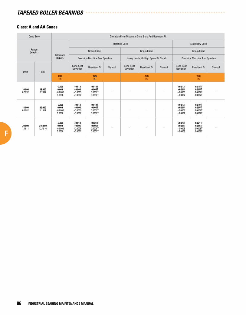
Cone Bore Deviation From Maximum Cone Bore And Resultant Fit
Range(mm/in.)
Tolerance(mm/in.)
Rotating Cone Stationary Cone
Ground Seat Ground Seat Ground Seat
Precision Machine Tool Spindles Heavy Loads, Or High Speed Or Shock Precision Machine Tool Spindles
Over Incl.
Cone Seat Deviation Resultant Fit Symbol Cone Seat
Deviation Resultant Fit Symbol Cone Seat Deviation Resultant Fit Symbol
mmin.
mmin.
mmin.
mmin.
10 .0000.3937
18 .0000.7087
-0 .0050 .000
-0.00020.0000
+0 .013+0 .005+0.0005+0.0002
0 .018T0 .005T0.0007T0.0002T
– – – –
+0 .013+0 .005+0.0005+0.0002
0 .018T0 .005T0.0007T0.0002T
–
18 .0000.7087
30 .0001.1811
-0 .0060 .000
-0.00020.0000
+0 .013+0 .005+0.0005+0.0002
0 .019T0 .005T0.0007T0.0002T
– – – –
+0 .013+0 .005+0.0005+0.0002
0 .019T0 .005T0.0007T0.0002T
–
30 .0001.1811
315 .00012.4016
-0 .0080 .000
-0.00030.0000
+0 .013+0 .005+0.0005+0.0002
0 .021T0 .005T0.0008T0.0002T
– – – –
+0 .013+0 .005+0.0005+0.0002
0 .021T0 .005T0.0008T0.0002T
–
Class: A and AA Cones
TAPERED ROLLER BEARINGS
INDUSTRIAL BEARING MAINTENANCE MANUAL86
F

Class: A and AA Cups
Cup O.D. Deviation From Maximum Cup O.D. And Resultant Fit
Range(mm/in.)
Tole
ranc
e(m
m/in
.)
Stationary Cup Stationary Cup Rotating Cup
Floating Clamped Adjustable Nonadjustable Or In Carriers Nonadjustable Or In Carriers
Over Incl.
Cup Seat Deviation
Resultant Fit Symbol Cup Seat
DeviationResultant
Fit Symbol Cup Seat Deviation
Resultant Fit Symbol Cup Seat
DeviationResultant
Fit Symbol Cup Seat Deviation
Resultant Fit Symbol
mmin.
mmin.
mmin.
mmin.
mmin.
mmin.
0 .0000.0000
315 .00012.4016
0 .000-0 .0080.0000-0.0003
+0 .008+0 .016+0.0003+0.0006
0 .008L0 .024L0.0003L0.0009L
–
0 .000+0 .0080.0000
+0.0003
0 .0000 .016L0.00000.0006L
–
-0 .0080 .000
-0.00030.0000
0 .008T0 .008L
0.0003T0.0003L
–
-0 .016-0 .008-0.0006-0.0003
0 .016T0 .000
0.0006T0.0000
–
-0 .024-0 .016-0.0009-0.0006
0 .024T0 .008T0.0009T0.0003T
–
TAPERED ROLLER BEARINGS
INDUSTRIAL BEARING MAINTENANCE MANUAL 87
F

SPHERICAL ROLLER BEARING
S
TAPERED ROLLER BEARINGS
INDUSTRIAL BEARING MAINTENANCE MANUAL88
F

SPHERICAL ROLLER BEARING
SG SPHERICAL ROLLER BEARINGS
Spherical Roller Bearings . . . . . . . . . . . . . . . . . . . . . . . . . . . . . . . 91
Storage And Handling . . . . . . . . . . . . . . . . . . . . . . . . . . . . . . . . . . . 92
s4 Fits . . . . . . . . . . . . . . . . . . . . . . . . . . . . . . . . . . . . . . . . . . . . . . . . . . 94
Mounting Procedures . . . . . . . . . . . . . . . . . . . . . . . . . . . . . . . . . . . 94
SAF Pillow Block Assemblies . . . . . . . . . . . . . . . . . . . . . . . . . . . 97
G G

SPHER
IC
AL ROLLER BEARINGS
GG

SPHER
IC
AL ROLLER BEARINGS
SPHERICAL ROLLER BEARINGSTimken® spherical roller bearings are designed to manage high radial loads even when misalignment, poor lubrication, contamination, extreme speeds or critical application stresses are present. Spherical bearings consist of an inner ring, outer ring, cage and center-rounded rollers. Types include:
• Type YM (precision-machined, roller-riding one piece brass cage): Ideal for extreme operating environments.
• Type YMB (precision-machined, land-riding one piece brass cage): Ideal for extreme operating environments.
• Type YMD (precision-machined, land-riding and two-pieced brass cages): Ideal for severe conditions.
• Type CJ (two-piece steel cage, window type): Suitable for a broad range of general service applications.
• Type VCSJ (stamped steel finger type): Suitable for general use.
Sizes: 25 mm bore and larger
Applications: Industrial applications for pulp and paper, power generation, oilfield, mining, aggregate, wind turbines, gear drives and rolling mills.
Customer Benefits: High load capacity even under misalignment conditions extends bearing life. Unit design simplifies bearing handling, installation and maintenance.
SPHERICAL ROLLER BEARINGS
INDUSTRIAL BEARING MAINTENANCE MANUAL 91
G

STORAGE AND HANDLING
See the General Bearing Handling and Inspection Section of this manual for guidelines regarding how to handle bearings.
New Timken bearings are normally distributed in packaging that provides necessary protection against dirt and moisture. There is no need to wash new bearings because the rust preventive on the bearing is compatible with normal lubricants. To prevent bearing contamination, do not remove the bearing from its packaging until ready for installation, and do not leave open bearings lying on the floor or workbench.
Even relatively minor mishandling or dropping the bearing can create damage that will result in significantly shorter bearing life.
Shaft
These charts provide guidelines for specifying shaft fits for spherical roller bearings in different operating conditions for solid steel shafts. For numerical values see pages 40-45.
Conditions ExamplesShaft Diameter
mmin.
ToleranceSymbol (1) Remarks
Bearings With Straight Bore
Stationary innerring load
The inner ring to be easilydisplaced on the shaft Two-bearing shaft mechanism See table on page 94 for
shaft size s4 See table on page 94 for shaft size
The inner ring not to bedisplaced on the shaft
Wheel on non-rotating shaft
All diameters
g6
Tension pulleys and rope sheaves h6
Rotating inner ring load or
indeterminateload direction
Light and variable loadsP ≤ 0.07C (2)
Electrical apparatus, machinetools, pumps, ventilators,
industrial trucks
Over18
0.7086100
3.9370
Incl.100
3.9370200
7.8740
k6m6
In very accurate applicationsk5 and m5 are used insteadof k6 and m6 respectively.
Normal and heavy loadsP > 0.07C (2)
≤ 0.25C (2)
General applications,electrical motors, turbines,
pumps, combustion engines,gear transmissions,
woodworking machines
180.7086
652.5590
1003.9370
1405.5118
28011.0236
50019.6850
652.5590
1003.9370
1405.5118
28011.0236
50019.6850and up
m5m6n6p6r6r7
Very heavy loadsand shock loads
P > 0.25C (2)
Journal boxes for locomotivesand other heavy rail vehicles,
traction motors
180.7086
652.5590
1003.9370
1405.5118
2007.8740
652.5590
1003.9370
1405.5118
2007.8740
50019.6850
m6n6p6r6r7
Bearings with greater clearancethan normal must be used.
Bearings With Tapered Bore And Adapter Sleeve
All loads Applications in general All diameters See tables for Reductionof RIC on page 97
Cleaning
See the General Bearing Handling and Inspection Section for information about proper cleaning and inspection techniques for all anti-friction bearings.
Installation
See the General Bearing Handling and Inspection Section for information about proper installation techniques for all anti-friction bearings.
See the Shaft and Housing Requirements Section for general information about checking and preparing shafts and housings prior to bearing installation.
(1) For solid steel shafts. See tables on pages 40-45 for numerical value.(2) C = Dynamic load rating.
SPHERICAL ROLLER BEARINGS
INDUSTRIAL BEARING MAINTENANCE MANUAL92
G

Housing
These charts provide guidelines for specifying housing fits for spherical roller bearings in different operating conditions.
Conditions Examples ToleranceSymbol (1) Remarks
Onepiece
bearinghousing
Rotatingouter
ring load
Variable load direction Two-bearing shaft mechanism P6
The outer ring is notdisplaceable axially
Heavy loads on bearings inthin walled housings
Supporting wheels in cranes,wheel hubs, crank bearings P7
Normal and heavy loads Wheel hubs, crank bearings N7
Light and variable loads Conveyor rollers,rope sheaves, tension pulleys
M7
Indeterminateload direction
Heavy shock loads Electrical traction motors
Heavy and normal loads, axialdisplacement of outer ring not required
Electrical motors, pumps,crankshaft main bearings K7 The outer ring is not
displaceable axially
Split orone piece
bearinghousing
Normal and light loads, axialdisplacement of the outer ring desirable
Electrical motors, pumps,crankshaft main bearings
J7 The outer ring isdisplaceable axially
Stationaryouter
ring load
Shock loads,temporarily complete unloading Journal boxes for rail vehicles
All loads Bearing applications in general,journal boxes for rail vehicles H7
The outer ring is easilydisplaced axially
Normal and light loads, loads undersimple operating conditions Line shaftings H8
Heat supplied through the shaft Dryer cylinders G7
Onepiece
bearinghousing
Applicationsrequiringparticularaccuracy
Very accurate running and smalldeflections under variable loads
For main spindles in machine tools
O.D. less than 125 mmO.D. 125 to 250 mmO.D. over 250 mm
M6N6P6
The outer ring is notdisplaced axially
Very accurate running under lightloads and indeterminate load direction
Held bearings in high speedcentrifugal force compressors K6 The outer ring is not
displaceable axially
Very accurate running, axialdisplacement of outer ring desirable
Floating bearings in high speedcentrifugal force compressors J6 The outer ring is easily
displaced axially
(1) For cast iron or steel housing. For numerical values see tables on pages 46-53. For housings of light metal, tolerances generally are selected which give a slightly tighter fit than those given in the table.
SPHERICAL ROLLER BEARINGS
INDUSTRIAL BEARING MAINTENANCE MANUAL 93
G

s4 FITS
A centrifugal force load produces a rotating outer ring load and a stationary inner ring load, even though the inner ring rotates. This makes it desirable to fit the outer ring tight in the housing, and the inner ring loose on the shaft using an s4 fit as listed in the table. The standard W33 bearing with oil groove and oil holes can be used.
Bore mm/in. Variance from Nominal Bore
Over Incl.
Tolerance+0
Shaft DiameterFit
Max. Min.
mmin.
mmin.
mmin.
50 .0001.9685
80 .0003.1996
-0 .015-0.0006
-0 .025-0.0010
-0 .036-0.0014
.010L .036L.0004L.0014L
80 .0003.1996
120 .0004.7294
-0 .020-0.0008
-0 .033-0.0013
-0 .043-0.0017
.013L .043L.0005L.0017L
120 .0004.7294
180 .0007.0866
-0 .025-0.0010
-0 .041-0.0016
-0 .053-0.0021
.015L .053L.0006L.0021L
180 .0007.0866
250 .0009.8425
-0 .030-0.0012
-0 .048-0.0019
-0 .064-0.0025
.018L .064L.0007L.0025L
MOUNTING PROCEDURES
Depending on the size of the bearing and the application, there are different methods for mounting roller bearings. In all methods, certain basic rules must be followed.
Cleanliness
• Choose a clean environment, free from dust or moisture.
• The installer should make every effort to ensure cleanliness by use of protective screens and clean cloths.
Plan the work
Know your plans in advance and have the necessary tools at hand. This reduces the amount of time for the job and decreases the chance for dirt to get into the bearing.
Inspection and preparation
• All component parts of the machine should be on hand and thoroughly cleaned before proceeding.
• Housings should be cleaned, including blowing out the oil holes.
• If blind holes are used, insert a magnetic rod to remove metal chips that might be lodged there during fabrication.
• Shaft shoulders and spacer rings contacting the bearing should be square with the shaft axis.
• The shaft fillet must be small enough to clear the radius of the bearing.
• On original installations, all component parts should be checked against the detail specification prints for dimensional accuracy. The shaft and housing should be carefully checked for size and form (roundness, etc.).
Shaft and housing finish
• Shaft surfaces on which the bearing will be mounted must be clean and free from nicks and burrs.
• For applications with a stationary housing and a rotating shaft, it is suggested that the bearing seat on the shaft be ground to 1.6 µm (65 Ra µin) maximum.
• If it is impractical to use a ground finish, a machined finish of 3.2 µm (125 Ra µin) is acceptable in many cases, but the amount of interference fit should be slightly increased.
• For a stationary outer ring, which is required to float (e.g., slide axially in the housing), a housing finish of 1.6 µm (65 Ra µin) maximum is suggested.
• Where the outer ring is not required to float, a surface finish of 3.2 µm (125 Ra µin) maximum.
Table 2 . s4 Fits .
The s4 fit designation as referenced on this page is a special fit tolerance developed by The Timken Company for this specific application. It DOES NOT conform to ISO standards similarly published as s4 preferred shaft fits.
SPHERICAL ROLLER BEARINGS
INDUSTRIAL BEARING MAINTENANCE MANUAL94
G

MOUNTING CYLINDRICAL BORE BEARINGS
Heat expansion method
• Most applications require a tight interference fit on the shaft.
• Mounting is simplified by heating the bearing to expand it suf-ficiently to slide easily onto the shaft.
• Two methods of heating are commonly used:
• Tank of heated oil.
• Induction heating.
Tank of heated oil
• The first is accomplished by heating the bearing in a tank of oil that has a high flash point.
• The oil temperature should not be allowed to exceed 120˚C (250˚F). A temperature of 90˚C (200˚F) is sufficient for most applications.
• The bearing should be heated for 20 or 30 minutes per inch of inner-ring cross section to fully heat in an oil tank.
• The bearing should not be in direct contact with the heat source.
• The usual arrangement is to have a screen several inches from the bottom of the tank. Small support blocks separate the bearing from the screen.
• It is important to keep the bearing away from any localized high-heat source that may raise its temperature excessively, resulting in race hardness reduction.
• Flame-type burners are commonly used. An automatic device for temperature control is desirable.
• If safety regulations prevent the use of an open heated oil bath, a mixture of 15 percent soluble-oil water may be used. This mixture may be heated to a maximum of 90˚C (200˚F) without being flammable.
Induction heating
• The induction heating method is used for mounting small bearings in production line assembly.
• Induction heating is rapid. Care must be taken to prevent bearing temperature from exceeding 120ºC (250ºF).
• Trial runs with the unit and bearing are usually necessary to obtain proper timing.
• Thermal crayons melting at predetermined temperatures can be used to check the bearing temperature.
• While the bearing is hot, it should be positioned squarely against the shoulder.
• Lockwashers and locknuts or clamping plates are then installed to hold the bearing against the shoulder of the shaft.
• As the bearing cools, the locknut or clamping plate should be tightened.
• In cases of outer ring rotation, where the outer ring is a tight fit in the housing, the housing member can be expanded by heating.
Arbor press method
• The alternate method of mounting, generally used only on smaller sizes, is to press the bearing onto the shaft or into the housing. This can be done by using an arbor press and a mounting tube.
• The tube can be made from soft steel with an inside diameter slightly larger than the shaft.
• The O.D. of the tube should not exceed the maximum shoulder height given in the table of dimensions.
• The tube should be faced square at both ends. It should be thoroughly clean inside and out, and long enough to clear the end of the shaft after the bearing is mounted.
• If the outer ring is being pressed into the housing, the O.D. of the mounting tube should be slightly smaller than the housing bore. The I.D. should not be less than the suggested housing backing diameter in the tables of dimensions.
• Coat the shaft with a light machine oil to reduce the force needed for a press fit.
• Carefully place the bearing on the shaft, making sure it is square with the shaft axis.
• Apply steady pressure from the arbor ram to drive the bearing firmly against the shoulder.
• Never attempt a press fit on a shaft by applying pressure to the outer ring, or a press fit in a housing by applying pressure to the inner ring.
Shaft Mounting Tapered Bore Spherical Roller Bearings
• Refer to the charts on pages 25 and 26 for the correct Reduction of RIC due to Installation.
• Place the bearing in an upright position with the inner and outer ring faces parallel.
• Place the thumbs on the inner ring bore and oscillate the inner ring two or three elements.
• Position the individual roller assemblies so that a roller is at the top of the inner ring on both sides of the bearing.
• With the roller in the correct position, insert a thin blade of the feeler gage between the roller and the outer ring.
• Move it carefully along the top roller, between the roller and outer ring raceway. Repeat this procedure, using thicker feeler gage blades, until one is found that will not go through.
SPHERICAL ROLLER BEARINGS
INDUSTRIAL BEARING MAINTENANCE MANUAL 95
G

• The blade thickness that preceded the “no-go” blade is a measure of radial internal clearance (RIC) before installation (Fig. 30).
• Start the mounting procedure by lubricating the tapered shaft with a light coat of machine oil.
• Slide the bearing onto the shaft as far as it will go.
• As the locknut is tightened, the interference fit builds up resulting in expansion of the inner ring.
• Periodically measure to keep track of the reduction in RIC.
• Continue the procedure until the proper amount of reduction is obtained. Do not exceed suggested amount of reduction.
• As a final check, make sure that the remaining RIC equals or exceeds the minimum mounted clearance.
• During mounting, the RIC should be checked at the unloaded roller. If this is at the bottom, make sure that the roller is raised to seat firmly at the inboard position of the inner race (Fig. 31).
• When the suggested amount of reduction of RIC has been accomplished, the bearing is properly fitted.
• Complete the procedure by peening the lockwasher tang into the locknut slot or securing the lockplate.
Example #1 - Calculating RIC Reduction Using a Spherical Roller Bearing with Tapered Bore
Given bearing number 22328K C3 (140 mm bore with a C3 clearance) is to be mounted on a tapered shaft. Using a set of feeler gauges, RIC is found to be –
RIC = 0.178 mm (0.007 in.)
Suggested reduction of RIC due to installation = 0.065 to 0.090 mm (0.0026 in. to 0.0035 in.), found in chart on page 97.
Calculate the clearance after mounting –
0.178 mm - 0.077 mm = 0.101 mm or
0.007 in. - 0.003 in. = 0.004 in.
NOTE: For this example, the value of 0.077 mm (0.003 in.) was obtained by taking the mid-range value of the upper and lower limits found in the table on page 97.
Therefore, the locking nut should be tightened until RIC reaches 0.101 mm (0.004 in.).
It should also be noted that the value obtained by reading the Suggested RIC after Installation directly from the table is 0.075 mm (0.0030 in.). This differs from the value calculated in the above example. The value taken directly from the table is provided as a minimum value. It is not suggested to use a calculated value that falls below this minimum.
Fig . 31 . During mounting, the RIC should be checked at the unloaded roller .
Fig . 30 . Measure of RIC before installation .
NOTE: Tapered bore bearings must have the proper amount of radial internal clearance before installation to provide for the required reduction of RIC during mounting and to compensate for any further internal reduction from abnormal temperature conditions. For special applications, send complete operating data to your Timken representative for suggestions on radial internal clearance.
SPHERICAL ROLLER BEARINGS
INDUSTRIAL BEARING MAINTENANCE MANUAL96
G

SAF PILLOW BLOCK ASSEMBLIES
Mounting adapters versus straight bore
Spherical roller bearing pillow block assemblies are typically mounted to a straight shaft using a tapered bore bearing and adapter assembly. Standard commercial shafting can be used without additional machining.
Adapter mounts also permit maximum flexibility in the axial positioning of the bearing on the shaft, and will accommodate light location thrust loads. Timken pillow blocks for tapered-bore and adapter-mounted bearings are available in Series 225, 226, 230, 231K and 232K.
Nominal Bearing Bore (mm)
Radial Internal Clearance Prior to Mounting (mm)Suggested Reduction
of RIC (mm)
Axial Displacement TaperedShaft Installation (mm)
Minimum Permissible RICAfter Installation
Normal C3 C4 1:12 Taper (1) 1:30 Taper (1) Normal C3 C4
over incl. Max. Min. Max. Min. Max. Min. Max. Min. Max. Min. Max. Min.
30 40 0 .050 0 .035 0 .065 0 .050 0 .085 0 .065 0 .025 0 .020 0 .380 0 .300 - - 0 .015 0 .025 0 .040
40 50 0 .060 0 .045 0 .080 0 .060 0 .100 0 .080 0 .030 0 .025 0 .460 0 .380 - - 0 .020 0 .030 0 .050
50 65 0 .075 0 .055 0 .095 0 .075 0 .120 0 .095 0 .040 0 .030 0 .560 0 .460 - - 0 .025 0 .040 0 .060
65 80 0 .095 0 .070 0 .120 0 .095 0 .150 0 .120 0 .050 0 .040 0 .760 0 .560 - - 0 .025 0 .045 0 .075
80 100 0 .110 0 .080 0 .140 0 .100 0 .180 0 .140 0 .065 0 .045 0 .970 0 .680 - - 0 .035 0 .050 0 .075
100 120 0 .135 0 .100 0 .170 0 .135 0 .220 0 .170 0 .070 0 .050 1 .070 0 .760 2 .540 1 .900 0 .050 0 .060 0 .100
120 140 0 .160 0 .120 0 .200 0 .160 0 .260 0 .200 0 .090 0 .065 1 .270 0 .890 3 .050 2 .290 0 .055 0 .075 0 .115
140 160 0 .180 0 .130 0 .230 0 .180 0 .300 0 .230 0 .100 0 .075 1 .520 1 .140 3 .430 2 .670 0 .055 0 .075 0 .125
160 180 0 .200 0 .140 0 .260 0 .200 0 .340 0 .260 0 .115 0 .075 1 .650 1 .140 4 .060 2 .670 0 .060 0 .090 0 .150
180 200 0 .220 0 .160 0 .290 0 .220 0 .370 0 .290 0 .125 0 .090 1 .900 1 .400 4 .450 3 .050 0 .070 0 .100 0 .165
200 225 0 .250 0 .180 0 .320 0 .250 0 .410 0 .320 0 .140 0 .100 2 .030 1 .520 4 .830 3 .560 0 .075 0 .115 0 .180
225 250 0 .270 0 .200 0 .350 0 .270 0 .450 0 .350 0 .150 0 .115 2 .290 1 .780 5 .330 4 .060 0 .090 0 .115 0 .200
250 280 0 .300 0 .220 0 .390 0 .300 0 .490 0 .390 0 .165 0 .115 2 .540 1 .780 5 .840 4 .060 0 .100 0 .140 0 .230
280 315 0 .330 0 .240 0 .430 0 .330 0 .540 0 .430 0 .180 0 .125 2 .670 1 .900 6 .220 4 .450 0 .100 0 .150 0 .250
315 355 0 .360 0 .270 0 .470 0 .360 0 .590 0 .470 0 .190 0 .140 2 .790 2 .030 6 .600 4 .830 0 .115 0 .165 0 .280
355 400 0 .400 0 .300 0 .520 0 .400 0 .650 0 .520 0 .200 0 .150 3 .050 2 .290 7 .110 5 .330 0 .130 0 .190 0 .330
400 450 0 .440 0 .330 0 .570 0 .440 0 .720 0 .570 0 .215 0 .165 3 .300 2 .540 7 .620 5 .840 0 .150 0 .230 0 .360
450 500 0 .490 0 .370 0 .630 0 .490 0 .790 0 .630 0 .230 0 .180 3 .430 2 .670 8 .000 6 .220 0 .165 0 .270 0 .410
500 560 0 .540 0 .410 0 .680 0 .540 0 .870 0 .680 0 .250 0 .200 3 .810 3 .050 8 .890 7 .110 0 .180 0 .290 0 .440
560 630 0 .600 0 .460 0 .760 0 .600 0 .980 0 .760 0 .280 0 .230 4 .190 3 .430 9 .780 8 .000 0 .200 0 .320 0 .510
630 710 0 .670 0 .510 0 .850 0 .670 1 .090 0 .850 0 .300 0 .250 4 .570 3 .810 10 .670 8 .890 0 .200 0 .370 0 .550
710 800 0 .750 0 .570 0 .960 0 .750 1 .220 0 .960 0 .350 0 .280 5 .330 4 .190 12 .450 9 .780 0 .230 0 .390 0 .610
800 900 0 .840 0 .640 1 .070 0 .840 1 .370 1 .070 0 .380 0 .300 5 .720 4 .570 13 .330 10 .670 0 .250 0 .460 0 .690
900 1000 0 .930 0 .710 1 .190 0 .930 1 .520 1 .190 0 .430 .0350 6 .480 5 .334 15 .110 12 .450 0 .280 0 .490 0 .750
1000 1120 1 .030 0 .770 1 .300 1 .030 1 .670 1 .300 0 .480 0 .400 7 .240 6 .100 16 .890 14 .220 0 .280 0 .550 0 .810
1120 1250 1 .120 0 .830 1 .420 1 .120 1 .830 1 .420 0 .500 0 .430 7 .620 6 .480 17 .780 15 .110 0 .330 0 .610 0 .910
Note: Axial displacement values apply to solid steel shafts or hollow steel shafts with bore diameter less than half the shaft diameter. For shaft materials other than steel, or for thin-wall shafts, please consult your Timken representative.
(1) 1:12 Taper used for 222, 223, 230, 231, 232, 233, 239 series. 1: 30 Taper used for 240, 241, 242 series. For sleeve mounting, multiply axial displacement values by 1.1 for 1:12 taper or by 1.05 for 1:30 taper. For questions on tapered shaft data, consult your Timken representative.
Mounting tapered bore spherical roller bearings
SPHERICAL ROLLER BEARINGS
INDUSTRIAL BEARING MAINTENANCE MANUAL 97
G

Adapter-mounted spherical roller bearings require the correct removal of RIC from the bearing to prevent relative rotation between the inner race and the sleeve or shaft. Failure to use proper mounting procedures can allow the inner race to slip on the shaft, creating heat and reducing bearing performance.
In applications with heavy thrust loads, or where exact axial location or a positive shaft interference fit are required, a direct straight bore mounting may be the best option. This requires a shouldered shaft, machined for proper fit and a straight bore bearing.
Timken pillow block assemblies for straight bore applications are available in Series 222, 223, 231 and 232. See pages 40-45 for suggested shaft diameters.
For applications involving heavy shock, vibration, unbalanced rotating loads or other abnormal conditions, consult your Timken representative.
Fixed and float pillow blocks
Any Timken pillow block can be easily installed in the float or fixed position on the shaft. For the fixed position, a stabilizing ring is added between the bearing outer ring face and the housing shoulder to positively locate the shaft and prevent axial movement.
Some applications require centering of the bearing in its housing. To accomplish this, two special width-stabilizing rings can be ordered.
Most Timken pillow blocks are supplied with a stabilizing ring. This should be discarded for the float positions. In the float position the ring is not used, allowing the bearing to move axially up to 9.5 mm (0.375 in.) to compensate for thermal expansion or contraction of the shaft.
Closed end installations
In some applications, the shaft end is designed to terminate inside the pillow block. For these designs, positive-fitting end closure inserts are available to seal out contaminants and retain lubricants.
Timken heavy duty end plugs include O-rings for positive sealing. When installing, make sure the shaft end does not contact the closure. A minimum of 3 mm (0.125 in.) clearance at maximum thermal expansion is suggested between the end of the shaft and the closure.
Dimension Y in the Timken Products Catalog tables defines the maximum permissible length of the shaft from the center line of the pillow block housing. If end closure is desired, specify by adding CL (one end closed) to the pillow block assembly number.
Mounting tapered-bore spherical roller bearings in an SAF assembly
Follow these general precautions when installing a tapered bore spherical roller bearing in an SAF assembly:
• The cap and base for each block are machined as one unit. Do not interchange components with other units.
• Make sure the LER seal rings have a good coating of grease over the entire ring after assembly. This ensures a proper seal for the block and prevents excess wear.
• Protect all unpainted metallic surfaces with clean, anti- corrosion solution.
• Cover the shaft and bearing with a clean shop towel if the assembly process is delayed.
• Make sure the shaft is free of burrs, nicks or damage and is properly sized.
Follow this procedure when installing a tapered bore spherical roller bearing in an SAF assembly:
• Slide the inboard seal on the shaft.
• Slide the adapter sleeve onto the shaft with the threads facing out. Laterally position this sleeve at the approximate center of the assembled bearing position.
• Slide the bearing onto the adapter sleeve and locate it on the shaft. For straight bore bearings, mount the bearing on the shaft as described on page 94. Make sure the inboard seal is on the shaft.
• If possible, leave the lock washer off at this point. Tighten the locknut with a 180º spanner wrench, measuring the RIC after each quarter turn, until the proper reduction of RIC is obtained. See RIC reduction in Section C (page 97) of this manual.
• Remove the locknut and place the lock washer against the bearing with the inner diameter prong pointing toward the bearing while in the groove in the sleeve. Find the lock washer tang that is closest to the locknut slot, and peen over the tang into the slot opening.
• Slide the outboard seal onto the shaft. Position both the inboard and outboard seals to line up with grooves in the housing block.
• Prepare the housing by removing any paint or burrs found on the split block’s mating surfaces, then oil the bearing seat.
SPHERICAL ROLLER BEARINGS
INDUSTRIAL BEARING MAINTENANCE MANUAL98
G

• Place the shaft with the mounted bearing into the pillow block base. Make sure the seals line up with the grooves in the housing.
• Bolt the housing to the mounting surface. Ensure the bearing outer ring sits squarely in the bearing seat.
• For axially fixed blocks, adjust the shaft if necessary, and insert the stabilizing ring between the bearing and the block shoulder on the locknut side, if possible.
• Adjust the other bearing(s) to the center(s) of their respective base(s). For high temperature applications, consult with your Timken representative for proper bearing placement in the base. Always fix only one pillow block on the shaft and allow the remaining bearing(s) to float on the shaft. This allows for axial expansion of the system.
• Apply grease or oil bath lubricant. See the Lubrication and Seals Section of this manual for more information.
• Prepare the cap by removing any paint or burrs found on the split block’s mating surfaces. Oil the bearing seat and lower the cap onto the base, aligning the dowel pins. Do not shear off dowel pins if the cap cannot be attached. If you have trouble aligning the dowel pins, rotate it 180º. Originally machined block halves should always be able to mate without modification.
• To prevent oil leakage, apply a small amount of sealing com-pound around the outer edges of the mating halves. Be careful not to apply too much as the compound can work into the bearing and result in an improper fit.
• Bolt the cap to its base using the bolts and washers provided. Torque all four bolts to standard bolt specs uniformly to maintain proper load distribution.
SPHERICAL ROLLER BEARINGS
INDUSTRIAL BEARING MAINTENANCE MANUAL 99
G

CYLINDRICAL ROLLER BEARINGS
SPHERICAL ROLLER BEARINGS
INDUSTRIAL BEARING MAINTENANCE MANUAL100
G

CYLINDRICAL ROLLER BEARINGSH CYLINDRICAL ROLLER BEARINGS
Cylindrical Roller Bearings . . . . . . . . . . . . . . . . . . . . . . . . . . . . . 103
Storage And Handling . . . . . . . . . . . . . . . . . . . . . . . . . . . . . . . . . . 104
Mounting Cylindrical Bore Bearings . . . . . . . . . . . . . . . . . . . . 104
H
H

CYLIN
DRICAL ROLLER BEARINGS
HH

CYLIN
DRICAL ROLLER BEARINGS
CYLINDRICAL ROLLER BEARINGSA radial cylindrical roller bearing consists of an inner and/or outer ring, a roller retaining cage and a complement of controlled contour cylindrical rollers. Timken cylindrical bearings provide the highest possible radial load capacity compared to other roller bearing types. Three basic styles are available to meet a variety of application requirements:
• One-row Cylindrical Bearings: Available in six types. Each has the same cage type, but inside and outside ring configura-tions vary to accommodate different application designs.
• Two-row Cylindrical Bearings: Customized designs are avail-able upon request (currently not a standard catalog item) and offer added radial capacity over traditional one-row types.
• Four-row Cylindrical Bearings: Has an extremely high radial load capacity, but no thrust capacity. Mostly used in roll neck applications in the metals industry.
Sizes: 15 mm – 2000 mm (0.591 in. to 78.740 in.) and 140 mm – 2000 mm (5.512 in. to 78.740 in.).
*The second size range is for four-row only.
Applications: Industrial applications for pulp and paper, power generation, oilfield, mining, aggregate, wind turbines, gear drives and rolling mills.
Design Attributes: The bearings can be selected with separable inner and outer races.
Customer Benefits: Heavy radial load capacity extends bearing life, reducing maintenance time and costs.
CYLINDRICAL ROLLER BEARINGS
INDUSTRIAL BEARING MAINTENANCE MANUAL 103
H

STORAGE AND HANDLING
See the General Bearing Handling and Inspection Section for guidelines regarding how to handle bearings.
New Timken bearings are normally distributed in packaging that provides necessary protection against dirt and moisture. There is no need to wash new bearings because the rust preventive on the bearing is compatible with normal lubricants. To prevent bearing contamination, do not remove the bearing from its packaging until ready for installation, and do not leave open bearings lying on the floor or workbench.
Cleaning
See the General Bearing Handling and Inspection Section for information about proper cleaning and inspection techniques for all anti-friction bearings.
Installation
See the General Bearing Handling and Inspection Section for information about proper installation techniques for all anti-friction bearings.
See the Shaft and Housing Requirements Section for general information about checking and preparing shafts and housings prior to bearing installation.
MOUNTING CYLINDRICAL BORE BEARINGS
Depending on the size of the bearing and the application, there are different methods for mounting roller bearings. In all methods, certain basic rules must be followed.
Cleanliness
• Choose a clean environment, free from dust or moisture.
• The installer should make every effort to ensure cleanliness by use of protective screens and clean cloths.
Plan the work
Know in advance your plans and have the necessary tools at hand. This reduces the amount of time for the job and decreases the chance for dirt to get into the bearing.
Inspection and preparation
• All component parts of the machine should be on hand and thoroughly cleaned before proceeding.
• Housings should be cleaned, including blowing out the oil holes.
• If blind holes are used, insert a magnetic rod to remove metal chips that might be lodged there during fabrication.
• Shaft shoulders and spacer rings contacting the bearing should be square with the shaft axis.
• The shaft fillet must be small enough to clear the radius of the bearing.
• On original installations, all component parts should be checked against the detail specification prints for dimensional accuracy. The shaft and housing should be carefully checked for size and form (roundness, etc.).
Shaft and housing finish
• Shaft surfaces on which the bearing will be mounted must be clean and free from nicks and burrs.
• For applications with a stationary housing and a rotating shaft, it is suggested that the bearing seat on the shaft be ground to 1.6 µm (65 Ra µin) maximum.
• If it is impractical to use a ground finish, a machined finish of 3.2 µm (125 Ra µin) is acceptable in many cases, but the amount of interference fit should be slightly increased.
• For a stationary outer ring, which is required to float (e.g., slide axially in the housing), a housing finish of 1.6 µm (65 Ra µin) maximum is suggested.
• Where the outer ring is not required to float, a surface finish of 3.2 µm (125 Ra µin) maximum is generally satisfactory.
Heat expansion method
• Most applications require a tight interference fit on the shaft.
• Mounting is simplified by heating the bearing to expand it suf-ficiently to slide easily onto the shaft.
• Two methods of heating are commonly used:
• Tank of heated oil.
• Induction heating.
Tank of heated oil
• The first is accomplished by heating the bearing in a tank of oil that has a high flash point.
• The oil temperature should not be allowed to exceed 120˚C (250˚F). A temperature of 90˚C (200˚F) is sufficient for most applications.
• The bearing should be heated for 20 or 30 minutes per inch of inner-ring cross section to fully heat in an oil tank.
• If safety regulations prevent the use of an open heated oil bath, a mixture of 15 percent soluble-oil water may be used. This mixture may be heated to a maximum of 93˚C (200˚F) without being flammable.
CYLINDRICAL ROLLER BEARINGS
INDUSTRIAL BEARING MAINTENANCE MANUAL104
H

• The bearing should not be in direct contact with the heat source.
• The usual arrangement is to have a screen several inches from the bottom of the tank. Small support blocks separate the bearing from the screen.
• It is important to keep the bearing away from any localized high-heat source that may raise its temperature excessively, resulting in race hardness reduction.
• Flame-type burners are commonly used. An automatic device for temperature control is desirable.
Induction heating
• The induction heating method is used for mounting small bearings in production line assembly.
• Induction heating is rapid. Care must be taken to prevent bearing temperature from exceeding 120˚C (250˚F).
• Trial runs with the unit and bearing are usually necessary to obtain proper timing.
• Thermal crayons melted at predetermined temperatures can be used to check the bearing temperature.
• While the bearing is hot, it should be positioned squarely against the shoulder.
• Lockwashers and locknuts or clamping plates are then installed to hold the bearing against the shoulder of the shaft.
• As the bearing cools, the locknut or clamping plate should be tightened.
• In cases of outer ring rotation, where the outer ring is a tight fit in the housing, the housing member can be expanded by heating.
Arbor press method
• The alternate method of mounting, generally used only on smaller sizes, is to press the bearing onto the shaft or into the housing. This can be done by using an arbor press and a mounting tube.
• The tube can be made from soft steel with an inside diameter slightly larger than the shaft.
• The O.D. of the tube should not exceed the maximum shoulder height given in the table of dimensions.
• The tube should be faced square at both ends. It should be thoroughly clean inside and out, and long enough to clear the end of the shaft after the bearing is mounted.
• If the outer ring is being pressed into the housing, the O.D. of the mounting tube should be slightly smaller than the housing bore. The I.D. should not be less than the suggested housing basking diameter in the tables of dimensions.
• Coat the shaft with a light machine oil to reduce the force needed for a press fit.
• Carefully place the bearing on the shaft, making sure it is square with the shaft axis.
• Apply steady pressure from the arbor ram to drive the bearing firmly against the shoulder.
• Never attempt a press fit on a shaft by applying pressure to the outer ring, or a press fit in a housing by applying pressure to the inner ring.
CAUTION Failure to observe the followingcautions could create a risk of injury:
If the bearing is to be reused or returned for repair, do not use heat from a torch.
Extreme heat from a torch can alter the bearing hardness and metallurgical structure, resulting in irreparable damage.
CYLINDRICAL ROLLER BEARINGS
INDUSTRIAL BEARING MAINTENANCE MANUAL 105
H

Shaft
(1) For solid shaft. See pages 40-45 for numerical values.
(2) Bearings with greater than nominal clearance must be used.
(3) Use k5 for accurate applications.
(4) Use m5 for accurate applications.
(5) C = Dynamic Load Rating.
(6) Use j5 for accurate applications.
These tables provide guidelines for shaft and housing fits related to particular operating conditions.
Housing
(1) For cast iron or steel housing. See pages 46-53 for numerical values.
Where wider tolerances are permissible, P7, N7, M7, K7, J7 and H7 values may be used in place of P6, N6, M6, K6, J6, and H6 values respectively.
Operating Conditions ExamplesHousing
TolerenceSymbol (1)
Outer RingDisplaceable
Axially
Outer Ring Rotating
Heavy loads withthin-wall housing
Crane support wheelsWheel hubs
(roller bearings)Crank bearings
P6 No
Normal toheavy loads
Wheel hubs(ball bearings)Crank bearings
N6 No
Light loadsConveyor rollers
Rope sheavesTension pulleys
M6 No
Indeterminate Load Direction
Heavy shock loads Electric traction motors M7 No
Normal to heavy loads,axial displacement
of outer ringnot required
Electric motorsPumps
Crankshaftmain bearings
K6 No,normally
Light to normal loads,axial displacement
of outer ring desired
Electric motorsPumps
Crankshaftmain bearings
J6 Yes,normally
Outer Ring Stationary
Shock loads,temporary complete
unloadingHeavy rail vehicles J6 Yes,
normally
All Loads
One-piece housing
General applications Heavy rail vehicles H6 Easily
Radiallysplit
housingTransmission drives H7 Easily
Heat suppliedthrough shaft Dryer cylinders G7 Easily
Cylindrical Roller Bearings (Except 5200 Series)
Operating Conditions Examples
LoadsShaft
Diametermmin.
Shaf
t Tol
eren
ce
Sym
bol (1
)
Lower Load Limit
Upper Load Limit
Inner Ring Stationary
Inner ringto beeasily
displacedon shaft
WheelsNon-rotating
shafts0 C (5) All g6
Inner ringdoes not
need to beeasily
displaced
Tensionpulleys 0 C All h6
Inner Ring Rotating, or Indeterminate
Overmmin.
Incl.mmin.
Light loads
Electrical apparatusMachine tools
PumpsVentilators
Industrial trucks
0 0.08C
0040
1.571405.51320
12.60500
19.68
401.571405.51320
12.60500
19.68––
j6 (6)
k6 (3)
m6 (4)
n6
p6
Normal loads
Electrical motorsTurbinesPumps
Combustion enginesGear transmissions
etc.
0.08C 0.18C
0040
1.571003.941405.51320
12.60500
19.68
401.571003.941405.51320
12.60500
19.68––
k5
m5
m6
n6
p6
r6
Heavy loadsShock loads
Rail vehiclesTractionmotors
0.18C C
0040
1.5765
2.561405.51320
12.60500
19.68
401.5765
2.561405.51320
12.60500
19.68––
m5 (3)
m6 (3)
n6 (3)
p6 (3)
r6 (3)
r7 (3)
Thrust Loads
Purethrust loads All Not recommended, consult Timken representative
* Below this line, housing can either be one piece or split; above this line, a split housing is not suggested.
CYLINDRICAL ROLLER BEARINGS
INDUSTRIAL BEARING MAINTENANCE MANUAL106
H

Bearing Bore BoreTolerance
+0
Press fit Rotating Inner Ring Slip Fit Stationary Inner Ring
Shaft DiameterFit
Shaft DiameterFit
Over Incl. Max. Min. Max. Min.
mmin.
mmin.
mmin.
mmin.
mmin.
mmin.
80 .0003.1496
120 .0004.7236
-0 .020-0.0008
0 .0480.0019
0 .0250.0010
0 .025T0.0010T
0 .069T0.0027T
0 .0000.0000
-0 .023-0.0009
.023L0.0009L
.020T.0008T
120 .0004.7236
140 .0005.5108
-0 .025-0.0100
0 .0560.0022
0 .0300.0012
0 .030T0.0012T
0 .081T0.0032T
0 .0000.0000
-0 .025-0.0010
.025L0.0010
.025T0.0010
140 .0005.5108
180 .0007.0856
-0 .025-0.0010
0 .0710.0028
0 .0460.0018
0 .046T0.0018T
0 .097T0.0038T
0 .0000.0000
-0 .025-0.0010
.025L0.0010
.025T0.0010
180 .0007.0856
240 .0009.4476
-0 .030-0.0012
0 .0810.0032
0 .0510.0020
0 .051T0.0020T
0 .112T0.0044T
0 .0000.0000
-0 .030-0.0012
.030L0.0012
.030T0.0012
Shaft fits(1)
(1) When shaft is used as race surface, hardness to be Rc58 minimum and surface finish to be 15 microinches Ra.
Bearing Bore O.D. Tolerance Inner Ring
+0
Press fit Rotating Inner Ring Slip Fit Stationary Inner Ring
Housing DiameterFit
Housing DiameterFit
Over Incl. Max. Min. Max. Min.
mmin.
mmin.
mmin.
mmin.
mmin.
mmin.
––
180 .0007.0866
-0 .025-0.0010
0 .0220.0008
-0 .015-0.0006
0 .015T0.0006T
0 .046L0.0018L
-0 .025-0.0010
-0 .056-0.0022
0 .056T0.0022T
0 .000L0.0000L
180 .0007.0866
200 .0007.874
-0 .030-0.0012
0 .0180.0007
-0 .018-0.0007
0 .018T0.0007T
0 .048L0.0019L
-0 .030-0.0012
-0 .066-0.0026
0 .066T0.0026T
0 .000L0.0000L
200 .0007.874
230 .0009.0551
-0 .030-0.0012
0 .0230.0009
-0 .018-0.0007
0 .018T0.007T
0 .053L0.0021L
-0 .030-0.0012
-0 .066-0.0026
0 .066T0.0026T
0 .000L0.0000L
230 .0009.0551
250 .0009.8425
-0 .030-0.0012
0 .0280.0011
-0 .018-0.0007
0 .018T0.0007T
0 .058L0.0023L
-0 .030-0.0012
-0 .066-0.0012
0 .066T0.0026T
0 .000L0.0000L
250 .0009.8425
270 .00010.6299
-0 .036-0.0014
0 .0280.0011
-0 .018-0.0007
0 .018T0.0007T
0 .064L0.0025L
-0 .030-0.0012
-0 .071-0.0028
0 .071T0.0028T
0 .005L0.0002L
270 .00010.6299
310 .00012.2047
-0 .036-0.0014
0 .0330.0013
-0 .018-0.0007
0 .018T0.0007T
0 .069L0.0027L
-0 .036-0.0014
-0 .071-0.0028
0 .071T0.0028T
0 .005L0.0002L
310 .00012.2047
400 .00015.748
-0 .041-0.0016
0 .0380.0015
-0 .018-0.0007
0 .018T0.0007T
0 .079L0.0031L
-0 .036-0.0014
-0 .076-0.0030
0 .079T0.0030T
0 .005L0.0002L
400 .00015.748
440 .00017.3228
-0 .046-0.0018
0 .0410.0016
-0 .023-0.0009
0 .023T0.0009T
0 .086L0.0034L
-0 .036-0.0034
-0 .086-0.0014
0 .086T0.0034T
0 .010L0.0004L
Housing fits
5200, A5200 Metric Series Shaft and Housing Fits and Tolerances
CYLINDRICAL ROLLER BEARINGS
INDUSTRIAL BEARING MAINTENANCE MANUAL 107
H

THRUST BEARINGS
Bearing Bore Radial Internal Clearance
Over Incl. Max. Min.
mmin.
mmin.
––
100 .0003.9370
0 .1830.0072
0 .1270.0050
100 .0003.9370
120 .0004.7244
0 .1880.0074
0 .1270.0050
120 .0004.7244
140 .0005.5118
0 .2080.0082
0 .1420.0056
140 .0005.5118
170 .0006.6929
0 .2240.0088
0 .1520.0060
170 .0006.6929
180 .0007.0866
0 .2290.0090
0 .1520.0060
180 .0007.0866
220 .0008.6614
0 .2540.0100
0 .1730.0068
220 .0008.6614
240 .0009.4488
0 .2690.0106
0 .1830.0072
Radial internal clearance (RIC)
Bearing Bore Bore &Inner O.D.
+0
Width+0
Over Incl.
mmin.
mmin.
mmin.
mmin.
80 .0003.1496
120 .0004.7244
-0 .020-0.0008
-0 .203-0.0080
120 .0004.7244
180 .0007.0866
-0 .025-0.0010
-0 .254-0.0100
180 .0007.0866
250 .0009.8425
-0 .030-0.0012
-0 .305-0.0120
Inner ring tolerances
Bearing O.D.O.D.+0
DiameterUnder Rollers
-0Over Incl.
mmin.
mmin.
mmin.
mmin.
150 .0005.9055
180 .0007.0866
-0 .025-0.0010
0 .0360.0014
180 .0007.0866
250 .0009.8425
-0 .030-0.0012
0 .0410.0016
250 .0009.8425
315 .00012.4016
-0 .036-0.0014
0 .0460.0018
315 .00012.4016
400 .00015.7480
-0 .041-0.0016
0 .0510.0020
400 .00015.7480
500 .00019.6850
-0 .046-0.0018
0 .0560.0022
Outer ring tolerances
BearingNumber
Slip Fit Housing (1) Press Fit Housing (1)
Max. Min. Max. Min.
mmin.
mmin.
mmin.
mmin.
5220 WS 121 .0644.7663
121 .0444.7655
121 .0364.7652
121 .0164.7644
5222 WS 133 .0075.2365
132 .9875.2357
132 .9695.2350
132 .9495.2343
5224 WS 145 .1945.7163
145 .1745.7155
145 .1565.7148
145 .1365.7140
5226 WS 155 .0426.1040
155 .0166.1030
155 .0046.1025
154 .9786.1015
5228 WS 168 .5296.6350
168 .5046.6340
168 .4916.6335
168 .4666.6325
5230 WS 181 .6237.1505
181 .5977.1495
181 .5877.1490
181 .5597.1480
5232 WS 193 .7137.6265
193 .6887.6255
193 .6757.6250
193 .6507.6240
5234 WS 205 .5628.0930
205 .5378.0920
205 .5248.0915
205 .4998.0905
5236 WS 216 .3708.5185
216 .3448.5175
216 .3198.5165
216 .2948.5155
5238 WS 229 .0329.0170
229 .0019.0158
228 .9949.0155
228 .9639.0143
5240 WS 242 .2969.5392
242 .2659.5380
242 .2459.5372
242 .2149.5360
5244 WM 266 .02010.4725
265 .97110.4713
265 .95110.4705
265 .9210.4693
5248WM 291 .29211.4682
291 .26211.4670
291 .24111.4662
291 .21111.4650
Shaft dimensions - 5200 bearings without inner ring
(1) All shaft diameters are based on a housing bore to housing O.D. ratio of 0.7.
CYLINDRICAL ROLLER BEARINGS
INDUSTRIAL BEARING MAINTENANCE MANUAL108
H

THRUST BEARINGS
I THRUST BEARINGS
Thrust Bearings . . . . . . . . . . . . . . . . . . . . . . . . . . . . . . . . . . . . . . . . 111
Storage And Handling . . . . . . . . . . . . . . . . . . . . . . . . . . . . . . . . . . 112
I
I

THRUST BEARINGS
II

THRUST BEARINGS
THRUST BEARINGSThrust bearings are designed specifically to manage heavy thrust loads and provide high-shock-load resistance for maximum bearing life and load capacity. Timken manufactures several basic thrust bearing designs, including:
• Ball Thrust Bearings: Standard axial (Type TVB) and an-gular contact (Types TVL and DTVL) ball thrust designs are available.
• Spherical Roller Thrust Bearings: Type TSR bearings are ideal for applications where conditions include heavy loads, difficulties in establishing or maintaining housing alignment and problems with shaft deflection.
• Cylindrical Roller Thrust Bearings: Designed to operate under heavy loads at moderate speeds. Types include standard (Type TP) and aligning washer (Type TPS).
• Tapered Roller Thrust Bearings: Ensures true rolling mo-tion for maximum bearing life and load-carrying capacity. Available in both standard (heavy duty, v-flat, screw down, oscillating and crossed roller) and custom designs.
Sizes: 35 mm – 2940 mm (1.375 in. to 115.75 in.)
Applications: Industrial applications such as cone crushers, crane hooks, oil well swivels, pulverizer drives, rolling mills, machine tool spindles and tables, drilling rig hydraulic heads, gearboxes and pre-heater fans.
Customer Benefits: Complete line offers application flexibility and provides maximum bearing life and load capacity for top performance and reduced maintenance.
Thrust bearings are typically used in applications with very high thrust and shock load applications.
THRUST BEARINGS
INDUSTRIAL BEARING MAINTENANCE MANUAL 111
I

Thrust ball bearings: Type TVB shaft Housing
Bearing Bore Nominal (Min.) Shaft Diameter
Over Incl. Max. Min.
mmin.
mmin.
mmin.
mmin.
0 .0000.0000
171 .4506.7500
+0+0
-0 .030-0.0012
171 .4506.7500
508 .00020.0000
+0+0
-0 .038-0.0015
Bearing Bore Nominal (Max.) Housing Bore
Over Incl. Max. Min.
mmin.
mmin.
mmin.
mmin.
119 .8584.7188
441 .32517.3750
+0 .229+0.0090
-0 .127-0.0050
441 .32517.3750
1000 .00039.3701
+0 .254+0.0100
-0 .152-0.0060
Bearing BoreNominal (Max.)
Shaft Diameter
Interference Fit (1) Loose Fit (2)
Over Incl. Max. Min. Max. Min.
mmin.
mmin.
mmin.
mmin.
mmin.
mmin.
0 .0000.0000
504 .82519.8750
+0 .076+0.0030
+0+0
-0 .152-0.0060
-0 .076-0.0030
504 .82519.8750
1524 .00060.0000
+0 .127+0.0050
+0+0
-0 .254-0.0100
-0 .127-0.0050
Bearing O.D.Nominal (Min.)
Shaft Diameter
Loose Fit (2) Interference Fit (1)
Over Incl. Max. Min. Max. Min.
mmin.
mmin.
mmin.
mmin.
mmin.
mmin.
0 .0000.0000
584 .00023.0000
+0 .152+0.0060
0 .0760.0030
-0 .152-0.0060
-0 .076-0.0030
584 .00023.0000
1778 .00070.0000
+0 .254+0.0100
0 .1270.0050
-0 .254-0.0100
-0 .127-0.0050
(1) Dowel pin suggested.
(2) Dowel pin required.
Thrust ball bearings: Type TVL and DTVL shaft Housing
STORAGE AND HANDLING
See the General Bearing Handling and Inspection Section for guidelines regarding how to handle bearings.
New Timken bearings are normally distributed in packaging that provides necessary protection against dirt and moisture. There is no need to wash new bearings because the rust preventive on the bearing is compatible with normal lubricants. To prevent bearing contamination, do not remove the bearing from its packaging until ready for installation, and do not leave open bearings lying on the floor or workbench.
Cleaning
See the General Bearing Handling and Inspection Section for information about proper cleaning and inspection techniques for all anti-friction bearings.
TTHD
Thrust Tapered Roller BearingsBearing Number Locations
TTVF
TP
TSR
TPS
TTVS
Thrust Cylindrical Roller BearingsBearing Number Locations
Thrust Spherical Roller BearingsBearing Number Locations
TVB TVL DTVL
Thrust Ball BearingsBearing Number Locations
(1) Dowel pin suggested.
(2) Dowel pin required.
Installation
See the General Bearing Handling and Inspection Section for information about proper installation techniques for all anti-friction bearings.
See the Shaft and Housing Requirements Section for general information about checking and preparing shafts and housings prior to bearing installation.
Thrust Roller Bearings Shaft and Housing Fits
Shaft and housing diameters shown as variance from nominal dimensions. Shaft and housing data shown in millimeters over inches.
THRUST BEARINGS
INDUSTRIAL BEARING MAINTENANCE MANUAL112
I

Type TP and TPS shaft
Bearing Bore Nominal (Max.) Shaft DiameterDeviation from Nominal Bore
Over Incl. Max. Min.
mmin.
mmin.
mmin.
mmin.
47 .6251.8750
53 .9752.1250
-0 .025-0.0010
-0 .051-0.0020
53 .9752.1250
63 .5002.5000
-0 .028-0.0011
-0 .053-0.0021
63 .5002.5000
76 .2003.0000
-0 .030-0.0012
-0 .056-0.0022
76 .2003.0000
88 .9003.5000
-0 .033-0.0012
-0 .058-0.0023
88 .9003.5000
177 .8007.0000
-0 .038-0.0015
-0 .064-0.0025
177 .8007.0000
228 .6009.0000
-0 .038-0.0015
-0 .076-0.0030
228 .6009.0000
304 .80012.0000
-0 .046-0.0018
-0 .084-0.0330
304 .80012.0000
381 .00015.0000
-0 .051-0.0020
-0 .089-0.0035
381 .00015.0000
482 .60019.0000
-0 .051-0.0020
-0 .102-0.0040
482 .60019.0000
584 .20023.0000
-0 .064-0.0025
-0 .114-0.0045
584 .20023.0000
762 .00030.0000
-0 .076-0.0030
-0 .140-0.0055
Type TP housing
Bearing O.D. Nominal (Min.) Housing BoreDeviation from Nominal O.D.
Over Incl. Max. Min.
mmin.
mmin.
mmin.
mmin.
115 .0924.5312
254 .00010.0000
+0 .076+0.0030
+0 .038+0.0015
254 .00010.0000
457 .20018.0000
+0 .102+0.0040
+0 .051+0.002
457 .20018.0000
558 .80022.0000
+0 .127+0.0050
+0 .064+0.0025
558 .80022.0000
660 .40026.0000
+0 .140+0.0055
+0 .064+0.0025
660 .40036.0000
711 .20028.0000
+0 .152+0.0060
+0 .076+0.0030
711 .20028.0000
863 .60034.0000
+0 .178+0.0070
+0 .076+0.0030
863 .60034.0000
965 .20038.0000
+0 .203+0.0080
+0 .089+0.0335
965 .20038.0000
1117 .60044.0000
+0 .229+0.0029
+0 .102+0.0040
TTHD
Thrust Tapered Roller BearingsBearing Number Locations
TTVF
TP
TSR
TPS
TTVS
Thrust Cylindrical Roller BearingsBearing Number Locations
Thrust Spherical Roller BearingsBearing Number Locations
TVB TVL DTVL
Thrust Ball BearingsBearing Number Locations
Thrust Cylindrical Roller Bearings
Tolerances for housing bore and for shaft diameters shown as variance from nominal bearing dimension. Data shown in millimeters over inches.
Bearing O.D. Nominal (Max.) Housing Diameter Deviation from DNominal O.D.
Over Incl. Max. Min.
mmin.
mmin.
mmin.
mmin.
50 .8002.0000
60 .3252.3750
+0 .038+0.0015
+0 .013+0.0005
60 .3252.3750
82 .5503.2500
+0 .043+0.0017
+0 .018+0.0070
82 .5503.2500
93 .6633.6875
+0 .048+0.0019
+0 .023+0.0009
93 .6633.6875
101 .6004.0000
+0 .053+0.0021
+0 .028+0.0011
101 .6004.0000
115 .0924.5312
+0 .071+0.0028
+0 .033+0.0013
115 .0924.5312
254 .00010.0000
+0 .076+0.0030
+0 .038+0.0015
254 .00010.0000
457 .20018.0000
+0 .102+0.0040
+0 .051+0.0020
457 .20018.0000
558 .80022.0000
+0 .127+0.0050
+0 .064+0.0025
558 .80022.0000
660 .40026.0000
+0 .140+0.0055
+0 .064+0.0025
660 .40026.0000
711 .20028.0000
+0 .152+0.0060
+0 .076+0.0030
711 .20028.0000
863 .60034.0000
+0 .078+0.0070
+0 .076+0.0030
863 .60034.0000
965 .20038.0000
+0 .203+0.0080
+0 .089+0.0035
965 .20038.0000
1117 .60044.0000
+0 .229+0.0090
+0 .102+0.0040
Type TPS housing
THRUST BEARINGS
INDUSTRIAL BEARING MAINTENANCE MANUAL 113
I

Thrust Tapered Roller Bearings
Tolerances for housing bore and shaft diameters shown as variance from nominal bearing dimension. Data shown in millimeters over inches. When one washer is piloted by the housing, sufficient clearances must be allowed at the outside diameter of the other
Types TTV and TTVF shaft Housing
Bearing Bore Nominal (Min.)
Shaft Diameter Max. Tolerance0 .000 mm0.000 in.
To
Over Incl. Min.
mmin.
mmin.
mmin.
0 .0000.0000
304 .80012.0000
-0 .051-0.0020
304 .80012.0000
508 .00020.0000
-0 .051-0.0020
508 .00020.0000
711 .20028.0000
-0 .076-0.0030
711 .20028.0000
1219 .20048.0000
-0 .102-0.0040
1219 .20048.0000
1727 .20068.0000
-0 .127-0.0050
Bearing Bore Nominal (Min.) Housing Bore
Over Incl. Max. Min.
mmin.
mmin.
mmin.
mmin.
161 .9256.3750
265 .11310.4375
0 .0600.0025
0 .0250.0010
265 .11310.3475
317 .50012.5000
0 .0760.0030
0 .0250.0010
317 .50012.5000
482 .60019.0000
0 .1020.0040
0 .0510.0020
482 .60019.0000
603 .25023.7500
0 .1130.0045
0 .0510.0020
603 .25023.7500
711 .20028.0000
0 .1520.0060
0 .0760.0030
711 .20028.0000
838 .20033.0000
0 .1780.0070
0 .0760.0030
Thrust tapered roller bearings: Type TTHD shaft Type TTHD housing
Bearing BoreNominal (Min.)
SpringLoadedMax.+0
Shaft Diameter
Rolling Mill Screwdown andPiercing Mill Thrust Blocks
Over Incl. Min. Max. Min.
mmin.
mmin.
mmin.
mmin.
mmin.
0 .0000.0000
174 .6256.8750
-0 .025-0.0010
+0 .076+0.0030
+0 .051+0.0020
174 .6256.8750
203 .1977.9999
-0 .025-0.0010
+0 .102+0.0040
+0 .076+0.0030
203 .1977.9999
304 .80012.0000
-0 .038-0.0015
+0 .127+0.0050
+0 .102+0.0040
304 .80012.0000
609 .60024.0000
-0 .051-0.0020
+0 .178+0.0070
+0 .127+0.0050
609 .60024.0000
914 .40036.0000
-0 .064-0.0025
+0 .241+0.0095
+0 .178+0.0070
914 .40036.0000
1219 .20048.0000
-0 .076-0.0030
+0 .304+0.0120
+0 .229+0.0090
Bearing O.D. Nominal (Min.) Housing Bore
Over Incl. Max. Min.
mmin.
mmin.
mmin.
mmin.
161 .9256.3750
266 .70010.5000
.0 .064+0.0025
+0 .025+0.0010
266 .70010.5000
330 .20013.0000
+0 .076+0.0030
+0 .025+0.0010
330 .20013.0000
508 .00020.0000
+0 .120+0.0040
+0 .051+0.0020
508 .00020.0000
635 .00025.0000
+0 .114+0.0045
+0 .051+0.0020
635 .00025.0000
762 .00030.0000
+0 .152+0.0060
+0 .076+0.0030
762 .00030.0000
889 .00035.0000
+0 .178+0.0070
+0 .076+0.0030
TTHD
Thrust Tapered Roller BearingsBearing Number Locations
TTVF
TP
TSR
TPS
TTVS
Thrust Cylindrical Roller BearingsBearing Number Locations
Thrust Spherical Roller BearingsBearing Number Locations
TVB TVL DTVL
Thrust Ball BearingsBearing Number Locations
washer as well as at the bore of both washers to prevent cross-threading of the rollers. For most applications, this clearance is approximately 1.588 mm (0.0625 inches).
THRUST BEARINGS
INDUSTRIAL BEARING MAINTENANCE MANUAL114
I

Type TSR shaft
Bearing O.D.Nominal (Max.)
Housing Bore
Springs in Housing Light Radial Load
Combined Axial and Radial Load
Stationary Outer Ring Rotating Outer Ring
Over Incl. Max. Min. Max. Min. Max. Min.
mmin.
mmin.
mmin.
mmin.
180 .0007.0866
250 .0009.8425
0 .0610.0024
0 .0150.0006
0 .0280.0011
-0 .018-0.0007
0 .0130.0005
-0 .033-0.0013
250 .0009.8425
315 .00012.4016
0 .0690.0027
0 .0180.0007
0 .0330.0013
-0 .018-0.0007
0 .0150.0006
-0 .036-0.0014
315 .00012.4016
400 .00015.7480
0 .0740.0029
0 .0180.0007
0 .0380.0015
-0 .018-0.0007
0 .0150.0006
-0 .041-0.0016
400 .00015.7480
500 .00019.6850
0 .0840.0033
0 .0200.0008
0 .0410.0016
-0 .023-0.0009
0 .0180.0007
-0 .046-0.0018
500 .00019.6850
630 .00024.8031
0 .0910.0036
0 .0230.0009
0 .0460.0018
-0 .023-0.0009
0 .0200.0008
-0 .048-0.0019
630 .00024.8031
800 .00031.4960
0 .1020.0040
0 .0230.0009
0 .0510.0020
-0 .023-0.0305
0 .0230.0009
-0 .051-0.0020
800 .00031.4960
1000 .00039.3700
0 .1090.0043
0 .0250.0010
0 .0580.0023
-0 .025-0.0010
0 .0250.0010
-0 .058-0.0023
1000 .00039.3700
1250 .00049.2126
0 .1220.0048
0 .0280.0011
0 .0660.0026
-0 .028-0.0011
0 .0300.0012
-0 .064-0.0025
Housing bore
Shaft diameter
Thrust Spherical Roller Bearings
Tolerances for housing bore and for shaft diameters shown as variance from nominal bearing dimension. Data shown in millimeters over inches. When application calls for thrust loads only, the housing must be relieved by 1.588 mm (0.0625 in.) on diameter so that no radial load is carried on the bearing (Fig. 32).
Bearing BoreNominal (Max)
Shaft Diameter
Stationary Load Rotating Load
Over Incl. Max. Min. Max. Min.
mmin.
mmin.
mmin.
mmin.
mmin.
mmin.
80 .0003.1496
120 .0004.7244
0 .0130.0005
-0 .010-0.0004
0 .0250.0010
0 .0030.0001
120 .0004.7244
180 .0007.0866
0 .0150.0006
-0 .010-0.0004
0 .0280.0011
0 .0030.0001
180 .0007.0866
200 .0007.8740
0 .0180.0007
-0 .013-0.0005
0 .0360.0001
0 .0050.0002
200 .0007.8740
240 .0009.4488
0 .0180.0007
-0 .013-0.0005
0 .0460.0018
0 .0150.0006
240 .0009.4488
315 .00012.4016
0 .0180.0007
-0 .015-0.0006
0 .0510.0020
0 .0200.0008
315 .00012.4016
400 .00015.7480
0 .0180.0007
-0 .018-0.0007
0 .0560.0022
0 .0200.0008
400 .00015.7480
500 .00019.6850
0 .0230.0009
-0 .018-0.0007
0 .0860.0034
0 .0460.0018
500 .00019.6850
630 .00024.8031
0 .0230.0009
-0 .020-0.0008
0 .0860.0034
0 .0430.0017
TTHD
Thrust Tapered Roller BearingsBearing Number Locations
TTVF
TP
TSR
TPS
TTVS
Thrust Cylindrical Roller BearingsBearing Number Locations
Thrust Spherical Roller BearingsBearing Number Locations
TVB TVL DTVL
Thrust Ball BearingsBearing Number Locations
Type TSR housing
Fig . 32 . The housing must be relieved by 1 .588 mm (0 .0625 in .) in diameter to ensure no radial load is carried .
THRUST BEARINGS
INDUSTRIAL BEARING MAINTENANCE MANUAL 115
I
BALL BEARINGS
THRUST BEARINGS
INDUSTRIAL BEARING MAINTENANCE MANUAL116
I

BALL BEARINGS
J BALL BEARINGS
Ball Bearings . . . . . . . . . . . . . . . . . . . . . . . . . . . . . . . . . . . . . . . . . . 119
Storage And Handling . . . . . . . . . . . . . . . . . . . . . . . . . . . . . . . . . . 120
Radial Internal Clearance . . . . . . . . . . . . . . . . . . . . . . . . . . . . . . 120
Shaft Fits . . . . . . . . . . . . . . . . . . . . . . . . . . . . . . . . . . . . . . . . . . . . . . 121
Housing Fits . . . . . . . . . . . . . . . . . . . . . . . . . . . . . . . . . . . . . . . . . . . 121
Wide Inner Ring Bearings . . . . . . . . . . . . . . . . . . . . . . . . . . . . . . 122
Ball Bearing Housed Units . . . . . . . . . . . . . . . . . . . . . . . . . . . . . 123
Mounting Wide Inner Ring Bearings And Housed Units . . 124
J
J

BALL BEARINGS
JJ

BALL BEARINGS
BALL BEARINGSTimken produces a broad range of Timken ball bearings to accommodate high precision applications at a variety of operating speeds. From standard deep groove radial ball bearings to advanced integral designs, Timken has the solution. Our ball bearing types include:
• Radial Ball Bearings: Tolerate relatively high-speed opera-tion under a range of load conditions. Bearings consist of an inner and outer ring with a cage containing a complement of precision balls.
• Angular Contact Ball Bearings: Designed for combination radial and axial loading and are used in agricultural, chemical, utility and general industries.
• Super-precision Ball Bearings: Designed to meet demand-ing application requirements and are manufactured to ISO P4 (ABEC-7) and ISO P2 (ABEC-9) tolerances. Include miniature and instrument, thin section and ball screw support bearings.
• Housed Units: A variety of housing and seal configurations are available to accommodate many industrial designs and operating environments.
Sizes: 3 mm – 600 mm bore (0.118 in. – 23.622 in.)
Applications: Aircraft, construction, agriculture, machine tool and general industry applications.
Design Attributes: Designs available for either standard industrial or high precision applications.
Customer Benefits: Supports high axial loads and provide optimum performance in high precision, harsh operating environments. Options are available to simplify mounting and maintenance.
BALL BEARINGS
INDUSTRIAL BEARING MAINTENANCE MANUAL 119
J

STORAGE AND HANDLING
See the General Bearing Handling and Inspection Section for general guidelines regarding how to handle ball bearings.
New Timken bearings are normally distributed in packaging that provides necessary protection against dirt and moisture. There is no need to wash new bearings because the rust preventive on the bearing is compatible with normal lubricants. To prevent bearing contamination, do not remove the bearing from its packaging until ready for installation, and do not leave open bearings lying on the floor or workbench.
Cleaning
See the General Bearing Handling and Inspection Section for information about proper cleaning and inspection techniques for all anti-friction bearings.
Installation
See the General Bearing Handling and Inspection Section for information about proper installation techniques for all anti-friction bearings.
See the Shaft and Housing Requirements Section for general information about checking and preparing shafts and housings prior to bearing installation.
Adjusting clearance
Standard manufacturing practice is to assemble ball bearings with a specified internal clearance. This clearance is necessary to allow for the effect of press fitting the bearing ring into its mounting during installation. In addition to allowing for thermal expansion of bearings, shafts and housings, this clearance can also provide a contact angle in the bearing after mounting.
Internal clearance can be measured either by gaging radially or axially. Radial measurement is accepted as the more significant characteristic because it is more directly related to shaft and housing fits. It is also the method prescribed by the ABMA.
RADIAL INTERNAL CLEARANCE
The radial internal clearance (RIC) of a radial contact ball bearing can be defined as follows:
Average outer ring race diameter
– Average inner ring race diameter
– 2 x ball diameter
= Radial internal clearance
RIC can be measured mechanically by moving the outer ring horizontally (Fig. 33).
The total movement of the outer ring when the balls are properly seated in the races determines the RIC. Several readings should be taken using different circumferential orientations of the rings in order to get a comprehensive average reading.
End play
End play is an alternate method of measuring internal clearance and is rarely used in radial ball bearings except for certain special applications. End play is determined by mounting the bearing with one of its rings clamped to prevent axial movement (Fig. 34).
A reversing measuring load is applied to the unclamped ring so that the resulting movement of that ring is parallel to the bearing axis. End play is the total movement of the unclamped ring when the load is applied first in one direction and then in the other.
Fig . 34 . Mounting the bearing with one of its rings clamped to prevent axial movement .
Fig . 33 . RIC can be measured mechanically by moving the outer ring horizontally .
BALL BEARINGS
INDUSTRIAL BEARING MAINTENANCE MANUAL120
J

SHAFT FITS
ABEC-1 (ISO PO) and ABEC-3 (ISO P6) ball bearing shaft and housing fits
The tables on pages 125-137 list actual shaft and housing dia-meters for ABEC-1 (ISO PO), ABEC-3 (ISO P6) and 7000WN angular contact product family of ball bearings. These recommendations can be used for most applications having light to normal loads. Shaft and housing fits for wide inner ring ball bearings are found on page 140.
ABEC-7 (ISO P4) shaft fits
As a general rule, the shaft size and tolerance for seating ABEC-7 (ISO P4) super-precision bearings should be the same as the bearing bore, creating line-to-line fit. For larger shaft sizes, the average fit increases to a slight interference fit.
HOUSING FITS
Most applications will have a rotating shaft and stationary outer ring. In these applications, the outer ring should be installed on the shaft with no more than hand pressure or light tapping. In applications where the housing rotates, the outer ring should be pressed into the housing with the same amount of pressure.
In general, the minimum housing bore dimension for super-precision bearings is the same as the maximum bearing outside diameter. If the bearing O.D. tolerance is 0.0076 mm (0.0003 in.), the maximum housing bore should be no more than 0.0076 mm (0.0003 in.) larger than the minimum housing bore dimension.
In high-speed applications, it is extremely important that the floating bearing or pair of bearings can move axially to compensate for thermal changes. The bearing(s) cannot float laterally if they are restricted by a tight housing bore or by the radial expansion of the bearing itself. Contact your Timken representative for assistance in unusual application conditions.
All shaft and housing shoulders must be absolutely square, and the faces of the spacers square and parallel.
Selective assembly
In some applications it may be desirable to control fits more accurately without the added expense of using closer-tolerance bearings and mating parts. This can be accomplished by selective assembly of bearings, shafts and housings after they have been sized and grouped according to bores and outside diameters. Generally, it is more satisfactory for production and servicing to use closer shaft and housing tolerances with bearings having a higher degree of precision. Bearings with coded bores and outside diameters are available on special order to facilitate this selective assembly process.
Shafts and housing fillets
The suggested shaft and housing fillet radii listed in the dimension tables of the product catalogs should be used to ensure proper seating of the bearings against the shaft and housing shoulders. The manufacturing tolerances on bearing corner radii are such that the corners will clear the catalog fillet radii when the bearings are tightly seated against the shoulders.
Shaft and housing radii and shoulders should be free from nicks and burrs. Whenever possible, bearing seats and adjacent shoulders should be undercut to help avoid tapered bearing seats and ensure clearing corners.
Shafts and housing finish
Suggested shaft finishes for ABEC-1 (ISO PO) bearing applications are shown on page 34. These figures are to be used as a guide only. Special situations may demand better finishes.
For additional information on shaft and housing finish, see the Shaft and Housing Requirements Section of this manual.
Housing shoulders
To ensure a proper seat for the bearing on a shaft or in a housing, the shoulders must be accurate and perpendicular to the shaft axis. The shoulders should be large enough to exceed the theoretical point of tangency between the corner radius and the face of the bearing, and small enough to permit bearing removal with proper pullers.
BALL BEARINGS
INDUSTRIAL BEARING MAINTENANCE MANUAL 121
J

H D
Fig . 35 . Wide inner ring ball bearing .
WIDE INNER RING BEARINGS
Timken originated the wide inner ring ball bearing designs that easily mount on straight shafts (Fig. 35). The internal bearing construction is basically the same as the deep-race, single-row radial type with the ability to carry radial, thrust and combined loads. The inner ring is generally extended on both sides of the race to provide additional shaft support, and is locked to the shaft by specially designed setscrews or by the Timken-originated, eccentric, self-locking collar or concentric collar.
Wide inner ring bearings are also available with cylindrical or spherical outside diameters. The cylindrical or straight O.D. type is used for mounting in straight-bored housings. The spherical O.D. type must be mounted in a corresponding spherical seat and is used to compensate for shaft or housing misalignments.
Shaft and housing considerations
When selecting shafts for use with wide inner ring bearings, a minimum slip fit is desirable for the most satisfactory mounting. Special shaft limits are required in certain cases, and a variety of standard fits can be used, even including a press fit. For housing bore and shoulder diameters, refer to the table on page 138.
The suggested figures are noted below, but in some applications it may be permissible to use increased shaft tolerances. Contact your Timken representative for assistance.
Bearing bore tolerance1/2 in. - 2 3/16 in. = nominal to +.013 mm (+.0005 in.)
2 1/4 in. - 3 3/16 in. = nominal to +.015 mm (+.0006 in.)
3 7/16 in. - 3 15/16 in. = nominal to +.018 mm (+.0007 in.)
Suggested shaft tolerances1/2 in. - 1 15/16 in. = nominal to -.013 mm (-.0005 in.)
2 in. - 3 15/16 in. = nominal to -.025 mm (-.0010 in.)
Bearings with locking collars
RR-series: These bearings feature the flare out, contact type R-seal that encloses a synthetic rubber impregnated washer between two metal caps. Most sizes incorporate a shroud seal design. (Fig. 36)
RA-RR series: The RA-RR Series features an extended inner ring and self-locking collar for simple effective shaft retention in a standard series bearing. The positive contact, land-riding R-seal provides improved protection against the heavy contamination
encountered in many applications. All sizes have a heat-stabilized, moisture-conditioned six/six nylon retainer that has proven extremely effective under conditions of misalignment. (Fig. 37)
Tri-ply-seal series: These bearings are designed for environments where severe conditions and moisture are present. The new one-piece tri-ply-seals incorporate a highly effective seal design molded to an exterior shroud cap. The shroud cap protects the seal lips from fiber wrap and abrasion while enhancing the overall sealing effectiveness of the unit. All units incorporate the self-locking collar and have a nylon retainer. (Fig. 38)
External self-aligning series: The construction of this series permits the inner assembly that contains an open-type ball bearing with spherical O.D. to align in the seat of the mating outer ring. The seat of this outer ring is matched with the spherical O.D. of the ball bearing outer ring providing unrestricted self-alignment that allows the inner assembly to become square and true with the shaft. (Fig. 39)
RA-DD series bearings: This series features an extended inner ring with cam locking collar. It incorporates two close-fitting non-contact grease shields to effectively retain lubricant and provide protection against harmful contaminants. The non-contact metallic shields provide improved high speed and low torque performance such as required for high speed printing press applications. The 6/6 molded nylon retainer has proven extremely effective under conditions of misalignment. These bearings are dimensionally interchangeable and have the same load capacities as the RA-RR series.
BALL BEARINGS
INDUSTRIAL BEARING MAINTENANCE MANUAL122
J

Wide inner ring bearings with concentric collars
GC-RRB series: These bearings are relubricated with spherical outside diameters, nylon retainers and shroud seals. The metal shroud maintains tight seal contact against the inner ring and shields the rubber seals from damage due to dirt or fiber wrap. The concentric collar is locked to the shaft by two setscrews, located 120° apart, which are mated with threaded holes in the collar and drilled holes in the bearing inner ring. (Fig. 40)
BALL BEARING HOUSED UNITS
Ball bearing housed units are available in a wide variety of types and sizes to accommodate a complete range of operating conditions. They generally have cast iron housings and are designed for mounting on straight shafts with a slip fit.
The self-locking collar and the setscrew inner bearing designs provide easy mounting. Bolt holes in housings take standard bolts for assembling these units to machinery frames. Several series are also available with the concentric-locking collar. Most of these units are self-aligning.
There are several basic types of housed units available: pillow blocks, flanged cartridges, flangette units, cylindrical cartridges and take-up units. The type required is generally determined by its application and mounting requirements. Within the basic type selected, numerous variations allow for load factors, shaft sizes, mounting surface dimensions, base-to-shaft center line heights and lubrication requirements.
Pillow blocks: These are the most commonly used type of mounted units, designed to provide shaft support where the mounting surface is parallel to the shaft axis. The bolt holes are usually slotted for adjustment during mounting (Fig. 41). Pillow blocks are supplied in both standard and heavy duty series. Pressed steel and rubber pillow blocks are also available for light duty applications.
Flanged cartridges: These housed units are used where a shaft passes through the machine frame at a right angle. A four-bolt mounting is the most common; however, where the mounting area is restricted, three and two-bolt versions are available. A piloted-flanged cartridge, also available, provides additional mounting accuracy and support. (Fig. 42)
Flanged cartridges are supplied in both standard and heavy duty series. Iron and rubber flanged cartridges are also available. A complete line of flangette units, pressed steel flanged cartridges, provides an economical solution to light duty applications. Two-, three- and four-bolt mountings are available along with a relubricating version.
Fig . 36 . RR-Series . Fig . 37 . RA-RR-Series .
Fig . 38 . Tri-ply Series . Fig . 39 . Externalself-aligning series .
Fig . 40 . GC-RRB series . Fig . 41 . Pillow block .
Fig . 42 . Flanged cartridge .
BALL BEARINGS
INDUSTRIAL BEARING MAINTENANCE MANUAL 123
J

Cylindrical cartridges: Like flanged cartridges, cylindrical cartridges provide shaft support where the shaft axis is perpendicular to and passing through a machined housing that is generally very thick. The outside diameter of the cylindrical cartridges permits mounting with a press fit into a straight, through-bored housing.
Cylindrical cartridges have a machined spherical bearing seat to provide initial shaft alignment in standard duty applications. Synthetic, conductive rubber cylindrical cartridges are also available for applications where low-cost, light-duty, low-noise operation is essential. (Fig. 43)
Take up units: These units are used where shaft adjustment and belt tightening devices are required, such as conveyor applications. Frames for take up units provide for either side or top mounting. Take up units are available in cast iron for standard-duty, and are available in pressed steel for economical, light-duty applications. (Fig. 44)
MOUNTING WIDE INNER RING BEARINGS AND HOUSED UNITS
Installing bearings with cam self-locking collars
Most Timken housed units come equipped with the self-locking collar to facilitate mounting the wide inner ring bearings. The self-locking collar eliminates the need for locknuts, washers, shoulders, sleeves and adapters.
The locking collar has a counter-bored recess that is made purposely eccentric to the bore. The collar recess and the end of the bearing inner ring with which it engages are both machined so that they act as mating cams when on the shaft. When the collar is engaged to the inner ring, it grips the shaft tightly with a positive binding action that increases with use. No adjustments are necessary.
• Slip the shaft through the pillow block or housed unit that incorporates the wide inner ring bearing. Be certain the bear-ing is aligned in position along the shaft. Do not tighten the locking mechanism at this time.
• Fasten the housed unit securely to its base using the proper bolt size.
• Place the self-locking collar on the shaft with its cam adjacent to the cam on the end of the bearing’s inner ring.
• Turn the collar in the direction of shaft rotation. The eccentric recessed cam will slide over and engage the corresponding cam on the bearing inner ring. Turn the collar until they are tightly engaged.
• Insert a drift pin in the collar hole. Using a lightweight ham-mer, strike the drift pin in the direction of the shaft rotation. This will lock the inner ring to the shaft.
• Tighten the setscrew in the collar. This exerts a wedging action to hold the collar in the engaged position, even under shock loads. In most cases, this design will operate effectively after the cams are tightly locked even without tightening the setscrews.
Installing bearings with concentric collars
On units equipped with concentric collar bearings, the collar is normally assembled to the wide inner ring for shipment. Slip the complete unit on the shaft following steps one and two described above, and tighten both setscrews.
Installing bearings with setscrews
• Slip the shaft through the pillow block or housed units that incorporates the wide inner ring bearing. Be certain the bearing is aligned in position along the shaft. Do not tighten the locking mechanism at this time.
• Fasten the housed unit securely to its base using the proper bolt size.
• Tighten each inner ring setscrew to the suggested torque listed by shaft size. It may be necessary to rotate the shaft to gain access to the setscrews.
Shaft Size Suggested Torque
mmin.
N-mlbs-in.
171⁄2 – 11⁄16
4 N-m35 lbs-in.
20-253⁄4 – 1
9 N-m80 lbs-in.
30-451 1⁄16 – 1 3⁄4
18 N-m155 lbs-in.
50-551 13⁄16 – 2 3⁄16
31 N-m275 lbs-in.
Table 3 . Suggested torque by shaft size .
Fig . 43 . Cylindrical cartridges . Fig . 44 . Take up units .
BALL BEARINGS
INDUSTRIAL BEARING MAINTENANCE MANUAL124
J

Radial ball bearing: shaft fits, ABEC-1 (ISO P0), ABEC-3 (ISO P6)
These tables are used for applications where only one ring, either inner or outer, has an interference fit with its shaft and housing. The guidelines for operating conditions covering these tables are found on page 134. In cases where interference fits are used for both rings, bearings with a special internal clearance may be required.
BasicBearingNumber
Bore ToleranceShaft Rotating, Load Stationary or Shaft Stationary, Load Rotating Shaft Stationary, Load Stationary or Shaft Rotating, Load Rotating
Shaft Diameter Mean Fit Tight Shaft Diameter Mean Fit Loose
Max. Min. Max. Min. ABEC-1 ABEC-3 Max. Min. ABEC-1 ABEC-3
mmin.
mmin.
mmin.
mmin.
mmin.
33K3, F33K3 3 .1750.1250
3 .1670.1247
3 .1800.1252
3 .1750.1250
0 .0060.00025
0 .0050.00020
3 .1700.1248
3 .1620.1245
0 .0050.00020
0 .0060.00025
33K4 3 .1750.1250
3 .1670.1247
3 .1800.1252
3 .1750.1250
0 .0060.00025
0 .0050.00020
3 .1700.1248
3 .1620.1245
0 .0050.00020
0 .0060.00025
33K5 4 .7620.1875
3 .7540.1872
4 .7680.1877
4 .7620.1875
0 .0060.00025
0 .0050.0002
4 .7520.1873
4 .7500.1870
0 .0050.00020
0 .0060.00025
34K 4 .0000.1575
3 .9920.1572
4 .0060.1577
4 .0010.1575
0 .0060.00025
0 .0050.0002
3 .9950.1573
3 .9880.1570
0 .0050.00020
0 .0060.00025
35K 5 .0000.1969
4 .9920.1966
5 .0060.1971
5 .0010.1969
0 .0060.00025
0 .0050.0002
4 .9960.1967
4 .9890.1964
0 .0050.00020
0 .0060.00025
36K 6 .0000.2362
5 .9920.2359
6 .0050.2364
5 .9990.2362
0 .0060.00025
0 .0050.0002
5 .9940.236
5 .9870.2357
0 .0050.00020
0 .0060.00025
37K 7 .0000.2756
6 .9920.2753
7 .0050.2758
6 .9980.2755
0 .0050.00020
0 .0040.00015
6 .9950.2754
6 .9850.275
0 .0060.00025
0 .0080.0003
38K, 38KV 8 .0000.3150
7 .9920.3147
8 .0060.3152
7 .9980.3149
0 .0050.00020
0 .0040.00015
7 .9960.3148
7 .9860.3144
0 .0060.00025
0 .0080.0003
39K 9 .0000.3543
8 .9920.3540
9 .0040.3545
8 .9970.3542
0 .0050.00020
0 .0040.00015
8 .9940.3541
8 .9840.3537
0 .0060.00025
0 .0080.0003
S1K,S1K7,FS1K7
6 .3500.2500
6 .3420.2497
6 .3550.2502
6 .3470.2499
0 .0050.00020
0 .0040.00015
6 .3450.2498
6 .3350.2494
0 .0060.00025
0 .0080.0003
S3K, FS3K 9 .5250.3750
9 .5170.3747
9 .5300.3752
9 .5220.3749
0 .0050.00020
0 .0040.00015
9 .5200.3748
9 .5100.3744
0 .0060.00025
0 .0080.0003
S5K 12 .7000.5000
12 .6920.4997
12 .7050.5002
12 .6970.4999
0 .0050.00020
0 .0040.00015
12 .6950.4998
12 .6820.4993
0 .0080.0003
0 .0090.00035
S7K 15 .8750.6250
15 .8670.6247
15 .8800.6252
15 .8720.6249
0 .0050.00020
0 .0040.00015
15 .8700.6248
15 .8570.6243
0 .0080.0003
0 .0090.00035
S8K 19 .0500.7500
19 .0400.7496
19 .0600.7504
19 .0530.7501
0 .0110.00045
0 .0090.00035
19 .0420.7497
19 .0300.7492
0 .0090.00035
0 .0110.00045
S9K 22 .2250.8750
22 .2150.8746
22 .2350.8754
22 .2280.8751
0 .0110.00045
0 .0090.00035
22 .2170.8747
22 .2050.8742
0 .0090.00035
0 .0110.00045
S10K 25 .4001.0000
25 .3900.9996
25 .4101.0004
25 .4031.0001
0 .0110.00045
0 .0090.00035
25 .3920.9997
25 .3800.9992
0 .0090.00035
0 .0110.00045
S11K 28 .5751.1250
28 .5651.1246
28 .5851.1254
28 .5781.1251
0 .0110.00045
0 .0090.00035
28 .5671.1247
28 .5551.1242
0 .0090.00035
0 .0110.00045
S12K 31 .7501.2500
31 .7371.2495
31 .7631.2505
31 .7531.2501
0 .0140.00055
0 .0110.00045
31 .7401.2496
31 .7251.249
0 .0110.00045
0 .0140.00055
F2DD-2 3 .1830.1253
3 .1750.1250
3 .1750.1250
3 .1670.1247
0 .0080.00030
0 .0060.00025
3 .1750.125
3 .1670.1247
0 .0080.0003
0 .0060.00025
F2 4 .7700.1878
4 .7620.1875
4 .7620.1875
4 .7550.1872
0 .0080.00030
0 .0060.00025
4 .7620.1875
4 .7550.1872
0 .0080.0003
0 .0060.00025
F3 4 .7700.1878
4 .7620.1875
4 .7620.1875
4 .7550.1872
0 .0080.00030
0 .0060.00025
4 .7620.1875
4 .7550.1872
0 .0080.0003
0 .0060.00025
F4 6 .3580.2503
6 .3500.2500
6 .3500.2500
6 .3420.2497
0 .0080.00030
0 .0060.00025
6 .3500.2500
6 .3420.2497
0 .0080.0003
0 .0060.00025
F5 7 .9460.3128
7 .9380.3125
7 .9380.3125
7 .9300.3122
0 .0080.00030
0 .0060.00025
7 .9380.3125
7 .9300.3122
0 .0080.0003
0 .0060.00025
Extra-Small 30, S, F - Flanged Series
Shaft diameter dimensions are for solid steel shafts. Contact your Timken representative regarding applications using hollow shafts.
BALL BEARINGS
INDUSTRIAL BEARING MAINTENANCE MANUAL 125
J

Radial ball bearing: shaft fits, ABEC-1 (ISO P0), ABEC-3 (ISO P6)
BasicBearingNumber
Bore ToleranceShaft Rotating, Load Stationary or Shaft Stationary, Load Rotating Shaft Stationary, Load Stationary or Shaft Rotating, Load Rotating
Shaft Diameter Mean Fit Tight Shaft Diameter Mean Fit Loose
Max. Min. Max. Min. ABEC-1 ABEC-3 Max. Min. ABEC-1 ABEC-3
mmin.
mmin.
mmin.
mmin.
mmin.
0 10 .0000.3937
9 .9920.3934
10 .0050.3939
9 .9970.3936
0 .0050.0002
0 .0040.00015
9 .9950.3935
9 .9850.3931
0 .0060.00025
0 .0080.00030
1 12 .0000.4724
11 .9920.4721
12 .0040.4726
11 .9960.4723
0 .0050.0002
0 .0040.00015
11 .9940.4722
11 .9810.4717
0 .0080.00030
0 .0090.00035
2 15 .0000.5906
14 .9920.5903
15 .0060.5908
14 .9990.5905
0 .0050.0002
0 .0040.00015
14 .9960.5904
14 .9830.5899
0 .0080.00030
0 .0090.00035
3 17 .0000.6693
16 .9920.6690
17 .0050.6695
16 .9980.6692
0 .0050.0002
0 .0040.00015
16 .9950.6691
16 .9820.6686
0 .0080.00030
0 .0090.00035
4 20 .0000.7874
19 .9900.7870
20 .0100.7879
20 .0020.7875
0 .0130.0005
0 .0090.00035
19 .9920.7871
19 .9800.7866
0 .0090.00035
0 .0110.00045
5 25 .0000.9843
24 .9900.9839
25 .0140.9848
25 .0040.9844
0 .0130.0005
0 .0090.00035
24 .9940.9840
24 .9810.9835
0 .0090.00035
0 .0110.00045
6 30 .0001.1811
29 .9901.1807
30 .0101.1816
30 .0021.1812
0 .0130.0005
0 .0090.00035
29 .9921.1808
29 .9801.1803
0 .0090.00035
0 .0110.00045
7 35 .0001.3780
34 .9871.3775
35 .0141.3785
35 .0041.3781
0 .0140.0006
0 .0110.00045
34 .9911.3776
34 .9761.377
0 .0110.00045
0 .0140.00055
8 40 .0001.5748
39 .9871.5743
40 .0131.5753
40 .0021.5749
0 .0140.0006
0 .0110.00045
39 .9901.5744
39 .9751.5738
0 .0110.00045
0 .0140.00055
9 45 .0001.7717
44 .9871.7712
45 .0141.7722
45 .0041.7718
0 .0140.0006
0 .0110.00045
44 .9911.7713
44 .9761.7707
0 .0110.00045
0 .0140.00055
10 50 .0001.9685
49 .9871.9680
50 .0131.9690
50 .0021.9686
0 .0140.0006
0 .0110.00045
49 .9901.9681
49 .9741.9675
0 .0110.00045
0 .0140.00055
11 55 .0002.1654
54 .9852.1648
55 .0162.1660
55 .0042.1655
0 .0170.0007
0 .0140.00055
54 .9912.165
54 .9732.1643
0 .0110.00045
0 .0140.00055
12 60 .0002.3622
59 .9852.3616
60 .0152.3628
60 .0022.3623
0 .0170.0007
0 .0140.00055
59 .9902.3618
59 .9722.3611
0 .0110.00045
0 .0140.00055
13 65 .0002.5591
64 .9852.5585
65 .0162.5597
65 .0042.5592
0 .0170.0007
0 .0140.00055
64 .9912.5587
64 .9732.5580
0 .0110.00045
0 .0140.00055
14 70 .0002.7559
69 .9852.7553
70 .0152.7565
70 .0022.7560
0 .0170.0007
0 .0140.00055
69 .9902.7555
69 .9722.7548
0 .0110.00045
0 .0140.00055
15 75 .0002.9528
74 .9852.9552
75 .0162.9534
75 .0042.9529
0 .0170.0007
0 .0140.00055
74 .9912.9524
74 .9732.9517
0 .0110.00045
0 .0140.00055
16 80 .0003.1496
79 .9853.149
80 .0153.1502
80 .0023.1497
0 .0170.0007
0 .0140.00055
79 .9903.1492
79 .9723.1485
0 .0110.00045
0 .0140.00055
17 85 .0003.3465
84 .9803.3457
85 .0193.3472
85 .0043.3466
0 .0200.0008
0 .0170.00065
84 .9883.346
84 .9683.3452
0 .0130.00050
0 .0170.00065
18 90 .0003.5433
89 .9803.5425
90 .0183.5440
90 .0023.5434
0 .0200.0008
0 .0170.00065
89 .9873.5428
89 .9673.542
0 .0130.00050
0 .0170.00065
19 95 .0003.7402
94 .9803.7394
95 .0193.7409
95 .0043.7403
0 .0200.0008
0 .0170.00065
94 .9883.7397
94 .9683.7389
0 .0130.00050
0 .0170.00065
20 100 .0003.9370
99 .9803.9362
100 .0183.9377
100 .0023.9371
0 .0200.0008
0 .0170.00065
99 .9873.9365
99 .9673.9357
0 .0130.00050
0 .0170.00065
21 105 .0004.1339
104 .9804.1331
105 .0194.1346
105 .0044.1340
0 .0200.0008
0 .0170.00065
104 .9884.1334
104 .9684.1326
0 .0130.00050
0 .0170.00065
22 110 .0004.3307
109 .9804.3299
110 .0184.3314
110 .0024.3308
0 .0200.0008
0 .0170.00065
109 .9874.3302
109 .9674.3294
0 .0130.00050
0 .0170.00065
9100, 9300, 200, 300, 5200, 5300 Series
BALL BEARINGS
INDUSTRIAL BEARING MAINTENANCE MANUAL126
J

Radial ball bearing: shaft fits, ABEC-1 (ISO P0), ABEC-3 (ISO P6)
BasicBearingNumber
Bore ToleranceShaft Rotating, Load Stationary or Shaft Stationary, Load Rotating Shaft Stationary, Load Stationary or Shaft Rotating, Load Rotating
Shaft Diameter Mean Fit Tight Shaft Diameter Mean Fit Loose
Max. Min. Max. Min. ABEC-1 ABEC-3 Max. Min. ABEC-1 ABEC-3
mmin.
mmin.
mmin.
mmin.
mmin.
124, 224, 324 120 .0004.7244
119 .9804.7236
120 .0184.7251
120 .0024.7245
0 .0200.0008
0 .0170.00065
119 .9874.7239
119 .9674.7231
0 .0130.0005
0 .0170.00065
126, 226, 326 130 .0005.1181
129 .9755.1171
130 .0205.1189
130 .0025.1182
0 .0240.0010
0 .0190.00075
129 .9845.1175
129 .9625.1166
0 .0140.00055
0 .0190.00075
128, 228, 328 140 .0005.5118
139 .9755.5108
140 .0205.5126
140 .0025.5119
0 .0240.0010
0 .0190.00075
139 .9845.5112
139 .9625.5103
0 .0140.00055
0 .0190.00075
9130, 130, 230, 330 150 .0005.9055
149 .9755.9045
150 .0205.9063
150 .0025.9056
0 .0240.0010
0 .0190.00075
149 .9845.9049
149 .9625.9040
0 .0140.00055
0 .0190.00075
9132, 132, 232 160 .0006.2992
159 .9756.2982
160 .0206.3000
160 .0026.2993
0 .0240.0010
0 .0190.00075
159 .9846.2986
159 .9626.2977
0 .0140.00055
0 .0190.00075
9134, 134, 234 170 .0006.6929
169 .9756.6919
170 .0206.6937
170 .0026.6930
0 .0240.0010
0 .0190.00075
169 .9846.6923
169 .9626.6914
0 .0140.00055
0 .0190.00075
9136, 136, 236, 336 180 .0007.0866
179 .9757.0856
180 .0207.0874
180 .0027.0867
0 .0240.0010
0 .0190.00075
179 .9847.0860
179 .9627.0851
0 .0140.00055
0 .0190.00075
9138, 138, 238, 338 190 .0007.4803
189 .9707.4791
190 .0257.4813
190 .0057.4805
0 .0300.0012
0 .0240.00095
189 .9847.4797
189 .9567.4786
0 .0140.00055
0 .0200.0008
9140, 240, 340 200 .0007.8740
199 .9697.8728
200 .0257.8750
200 .0057.8742
0 .0300.0012
199 .9847.8734
199 .9547.8722
0 .0150.0006
9142, 240, 340 210 .0008.2677
212 .5098.2665
209 .7718.2587
210 .0028.2678
0 .0300.0012
209 .9878.2672
209 .9518.2658
0 .0150.0006
9144, 244, 344 220 .0008.6614
219 .9698.6602
220 .0258.6624
220 .0058.6616
0 .0300.0012
219 .9848.6608
219 .9548.6596
0 .0150.0006
9146, 246 230 .0009.0551
229 .9699.0539
230 .0259.0561
230 .0059.0553
0 .0300.0012
230 .0229.0545
229 .9519.0533
0 .0150.0006
248, 348 240 .0009.4488
239 .9699.4476
240 .0259.4498
240 .0059.4490
0 .0300.0012
239 .9849.4482
239 .9549.4470
0 .0150.0006
250 250 .0009.8425
249 .9649.8411
250 .0209.8434
250 .0059.8426
0 .0300.0012
250 .0229.8418
249 .9729.8406
0 .0150.0006
9152, 252, 352 260 .00010.2362
259 .96410.2348
260 .02710.2373
260 .00510.2364
0 .0360.0014
259 .98210.2355
259 .95110.2343
0 .0150.0006
9156, 256, 356 280 .00011.0236
279 .96411.0222
280 .02711.0247
280 .00511.0238
0 .0360.0014
279 .98211.0229
279 .95111.0217
0 .0150.0006
9160, 260 300 .00011.8110
299 .96411.8096
300 .02711.8121
300 .00511.8112
0 .0360.0014
299 .98211.8103
299 .95111.8091
0 .0150.0006
9164, 264 320 .00012.5984
319 .96412.5970
320 .03012.5996
320 .00512.5986
0 .0380.0015
319 .98212.5977
319 .94612.5963
0 .0150.0006
9180 400 .00015.7480
399 .96915.7464
400 .03015.7492
400 .00515.7482
0 .0380.0015
399 .98215.7473
399 .94615.7459
0 .0150.0006
Extra large series
BALL BEARINGS
INDUSTRIAL BEARING MAINTENANCE MANUAL 127
J

Radial ball bearing: shaft fits, ABEC-1 (ISO P0), ABEC-3 (ISO P6)
Bearing Bore Number
Bearing Bore, Diameter Shaft Rotating, Load Stationary, Shaft Diameter Mean Tight Fit
Max. Min. Max. Min.
mmin.
mmin.
mmin.
mmin.
mmin.
00 10 .0000.3937
9 .9920.3934
9 .9970.3936
10 .0050.3939
0 .0050.0002
01 12 .0000.4724
11 .9910.4721
11 .9960.4723
12 .0040.4726
0 .0050.0002
02 15 .0000.5906
14 .9940.5903
14 .9990.5905
15 .0060.5908
0 .0050.0002
03 17 .0000.6693
16 .9930.6690
16 .9980.6692
17 .0050.6695
0 .0050.0002
04 20 .0000.7874
19 .9920.7871
19 .9970.7873
20 .0050.7876
0 .0050.0002
05 25 .0000.9843
24 .9940.9840
24 .9990.9842
25 .0060.9845
0 .0050.0002
06 30 .0001.1811
29 .9921.1808
29 .9971.1810
30 .0051.1813
0 .0050.0002
07 35 .0001.3780
34 .9941.3777
34 .9991.3779
35 .0091.3783
0 .0060.00025
08 40 .0001.5748
39 .9921.5745
39 .9971.5747
40 .0081.5751
0 .0060.00025
09 45 .0001.7717
44 .9941.7714
44 .9991.7716
45 .0091.7720
0 .0060.00025
10 50 .0001.9685
49 .9921.9682
49 .9971.9684
50 .0081.9688
0 .0060.00025
11 55 .0002.1654
54 .9912.165
54 .9992.1653
55 .0112.1658
0 .0090.00035
12 60 .0002.3622
59 .9902.3618
59 .9972.3621
60 .0102.3626
0 .0090.00035
13 65 .0002.5591
64 .9912.5587
64 .9992.5590
65 .0112.5595
0 .0090.00035
14 70 .0002.7559
69 .9902.7555
69 .9972.7558
70 .0102.7563
0 .0090.00035
15 75 .0002.9528
74 .9912.9524
74 .9992.9527
75 .0112.9532
0 .0090.00035
16 80 .0003.1496
79 .9903.1492
79 .9973.1495
80 .0103.1500
0 .0090.00035
17 85 .0003.3465
84 .9883.3460
84 .9993.3464
85 .0143.3470
0 .0110.00045
18 90 .0003.5433
89 .9873.5428
89 .9973.5432
90 .0133.5438
0 .0110.00045
19 95 .0003.7402
94 .9883.7397
94 .9993.7401
95 .0143.7407
0 .0110.00045
20 100 .0003.9370
99 .9873.9365
99 .9973.9369
100 .0133.9375
0 .0110.00045
21 105 .0004.1339
104 .9884.1334
104 .9994.1338
105 .0144.1344
0 .0110.00045
22 110 .0004.3307
109 .9874.3302
109 .9974.3306
110 .0124.3312
0 .0110.00045
24 120 .0004.7244
119 .9874.7239
119 .9974.7243
120 .0124.7249
0 .0110.00045
26 130 .0005.1181
129 .9825.1174
129 .9975.118
130 .0155.1187
0 .0150.0006
28 140 .0005.5118
139 .9825.5111
139 .9975.5117
140 .0155.5124
0 .0150.0006
30 150 .0005.9055
149 .9825.9048
149 .9975.9054
150 .0155.9061
0 .0150.0006
BALL BEARINGS
INDUSTRIAL BEARING MAINTENANCE MANUAL128
J

Bearing Bore Number
Bearing Bore, Diameter
These diameters result in shaft to bearing bore fit whichclosely conforms to j5 listed on pages 40-45.
Mean Tight FitShaft Rotating, Load Stationary, Shaft Diameter
Max. Min. Min. Max.
mmin.
mmin.
mmin.
mmin.
mmin.
00 10 .0000.3937
9 .9920.3934
9 .9970.3936
10 .0050.3939
0 .005 0.0002
01 12 .0000.4724
11 .9910.4721
11 .9960.4723
12 .0040.4726
0 .0050.0002
02 15 .0000.5906
14 .9940.5903
14 .9990.5905
15 .0060.5908
0 .0050.0002
03 17 .0000.6693
16 .9930.6690
16 .9980.6692
17 .0050.6695
0 .0050.0002
04 20 .0000.7874
19 .9920.7871
19 .9970.7873
20 .0050.7876
0 .005 0.0002
05 25 .0000.9843
24 .9940.9840
24 .9990.9842
25 .0060.9845
0 .005 0.0002
06 30 .0001.1811
29 .9921.1808
29 .9971.1810
30 .0051.1813
0 .005 0.0002
07 35 .0001.3780
34 .9941.3777
34 .9991.3779
35 .0091.3783
0 .006 0.00025
08 40 .0001.5748
39 .9921.5745
39 .9971.5747
40 .0081.5751
0 .006 0.00025
09 45 .0001.7717
44 .9941.7714
44 .9991.7716
45 .0091.7720
0 .0060.00025
10 50 .0001.9685
49 .9921.9682
49 .9971.9684
50 .0081.9688
0 .006 0.00025
11 55 .0002.1654
54 .9912.1650
54 .9992.1653
55 .0112.1658
0 .009 0.00035
12 60 .0002.3622
59 .9902.3618
59 .9972.3621
60 .0102.3626
0 .009 0.00035
13 65 .0002.5591
64 .9912.5587
64 .9992.5590
65 .0112.5595
0 .0090.00035
14 70 .0002.7559
69 .9902.7555
69 .9972.7558
70 .0102.7563
0 .009 0.00035
15 75 .0002.9528
74 .9912.9524
74 .9992.9527
75 .0112.9532
0 .009 0.00035
16 80 .0003.1496
79 .9903.1492
79 .9973.1495
80 .0103.1500
0 .0090.00035
17 85 .0003.3465
84 .9883.3460
84 .9993.3464
85 .0143.3470
0 .011 0.00045
18 90 .0003.5433
89 .9873.5428
89 .9973.5432
90 .0133.5438
0 .011 0.00045
19 95 .0003.7402
94 .9883.7397
94 .9993.7401
95 .0143.7407
0 .0110.00045
20 100 .0003.9370
99 .9873.9365
99 .9973.9369
100 .0133.9375
0 .011 0.00045
21 105 .0004.1339
104 .9884.1334
104 .9994.1338
105 .0144.1344
0 .011 0.00045
22 110 .0004.3307
109 .9874.3302
109 .9974.3306
110 .0124.3312
0 .011 0.00045
24 120 .0004.7244
119 .9874.7239
119 .9974.7243
120 .0124.7249
0 .0110.00045
26 130 .0005.1181
129 .9825.1174
129 .9975.1180
130 .0155.1187
0 .015 0.0006
28 140 .0005.5118
139 .9825.5111
139 .9975.5117
140 .0155.5124
0 .015 0.0006
30 150 .0005.9055
149 .9825.9048
149 .9975.9054
150 .0155.9061
0 .0150.0006
Shaft and housing shoulder
Shaft fits, 7000WN single row angular contact bearings
BALL BEARINGS
INDUSTRIAL BEARING MAINTENANCE MANUAL 129
J

Radial ball bearing: housing fits, ABEC-1 (ISO P0), ABEC-3 (ISO P6)
Basic Bearing Number Housing Stationary, Load Stationary orHousing Rotating, Load Rotating
Housing Rotating, Load Stationary orHousing Stationary, Load Rotating
Extra Small Extra Light Light Medium Heavy Housing Bore Mean Fit Loose Housing Bore Mean Fit Tight
30, S, FSeries
9100,9300
Series
200,7200
Series
300,7300
Series
7400Series
Max. Min. ABEC-1 ABEC-3 Max. Min. ABEC-1 ABEC-3
mmin.
mmin.
mmin.
mmin.
33K3, F33K3 – – – – 9 .5350.3754
9 .5250.3750
0 .0100.00040
0 .0090.00035
9 .5250.3750
9 .5070.3743
0 .0040.00015
0 .0050.00020
33K4 – – – – 12 .7100.5004
12 .7000.5000
0 .0100.00040
0 .0090.00035
12 .7000.5000
12 .6820.4993
0 .0040.00015
0 .0050.00020
33K5, F33K5 – – – – 12 .7100.5004
12 .7000.5000
0 .0100.00040
0 .0090.00035
12 .7000.5000
12 .6820.4993
0 .0040.00015
0 .0050.00020
34K – – – – 16 .0100.6303
15 .9990.6299
0 .0100.00040
0 .0090.00035
15 .9990.6299
15 .9820.6292
0 .0040.00015
0 .0050.00020
35K – – – – 19 .0120.7485
18 .9990.7480
0 .0110.00045
0 .0100.00040
18 .9990.7480
18 .9790.7472
0 .0050.00020
0 .0060.00025
36K – – – – 19 .0120.7485
18 .9990.7480
0 .0110.00045
0 .0100.00040
18 .9990.7480
18 .9790.7472
0 .0050.00020
0 .0060.00025
37K – – – – 22 .0120.8666
21 .9990.8661
0 .0110.00045
0 .0100.00040
29 .9990.8661
21 .9790.8653
0 .0050.00020
0 .0060.00025
38K – – – – 22 .0120.8666
21 .9990.8661
0 .0110.00045
0 .0100.00040
21 .9990.8661
21 .9790.8653
0 .0050.00020
0 .0060.00025
38KV – – – – 24 .0130.9454
24 .0000.9449
0 .0110.00045
0 .0100.00040
24 .0000.9449
23 .9800.9441
0 .0050.00020
0 .0060.00025
39K 9100 – – – 26 .0121.0241
25 .9991.0236
0 .0110.00045
0 .0100.00040
25 .9991.0236
25 .9791.0228
0 .0050.00020
0 .0060.00025
S1K7, FS1K7 – – – – 15 .8850.6254
15 .8750.6250
0 .0100.00040
0 .0090.00035
15 .8750.6250
15 .8570.6243
0 .0040.00015
0 .0050.00020
S1K – – – – 19 .0630.7505
19 .0500.7500
0 .0110.00045
0 .0100.00040
19 .0500.7500
19 .0300.7492
0 .0050.00020
0 .0060.00025
S3K, FS3K – – – – 22 .2380.8755
22 .2250.8750
0 .0110.00045
0 .0100.00040
22 .2250.8750
22 .2050.8742
0 .0050.00020
0 .0060.00025
S5K – – – – 28 .5881.1255
28 .5751.1250
0 .0110.00045
0 .0100.00040
28 .5751.1250
28 .5551.1242
0 .0050.00020
0 .0060.00025
S7K – – – – 34 .9401.3756
34 .9251.3750
0 .0140.00055
0 .0110.00045
34 .9251.3750
34 .9001.3740
0 .0060.00025
0 .0090.00035
S8K – – – – 41 .2901.6256
41 .2751.6250
0 .0140.00055
0 .0110.00045
41 .2751.6250
41 .2501.6240
0 .0060.00025
0 .0090.00035
S9K – – – – 47 .6401.8756
47 .6251.8750
0 .0140.00055
0 .0110.00045
47 .6251.8750
47 .6001.8740
0 .0060.00025
0 .0090.00035
S10K – – – – 50 .8182.0007
50 .8002.0000
0 .0150.00060
0 .0140.00055
50 .8002.0000
50 .7701.9988
0 .0090.00035
0 .0100.00040
S11K – – – – 53 .9932.1257
53 .9752.1250
0 .0150.00060
0 .0140.00055
53 .9752.1250
53 .9452.1238
0 .0090.00035
0 .0100.00040
S12K – – – – 57 .1682.2507
57 .1502.2500
0 .0150.00060
0 .0140.00055
57 .1502.2500
57 .1202.2488
0 .0090.00035
0 .0100.00040
F2002 – – – – 9 .5330.3753
9 .5250.3750
0 .0000.00000
0 .0000.00000
9 .5330.3753
9 .5220.3749
0 .0000.00000
0 .0000.00000
F2 – – – – 11 .1200.4378
11 .1120.4375
0 .0000.00000
0 .0000.00000
11 .1200.4378
11 .1100.4374
0 .0000.00000
0 .0000.00000
F3 – – – – 14 .2950.5628
14 .2850.5624
0 .0000.00000
0 .0000.00000
14 .2950.5628
14 .2850.5624
0 .0000.00000
0 .0000.00000
BALL BEARINGS
INDUSTRIAL BEARING MAINTENANCE MANUAL130
J

Basic Bearing Number Housing Stationary, Load Stationary orHousing Rotating, Load Rotating
Housing Rotating, Load Stationary orHousing Stationary, Load Rotating
Extra Small Extra Light Light Medium Heavy Housing Bore Mean Fit Loose Housing Bore Mean Fit Tight
30, S, FSeries
9100,9300
Series
200,7200
Series
300,7300
Series
7400Series
Max Min ABEC-1 ABEC-3 Max Min ABEC-1 ABEC-3
mmin.
mmin.
mmin.
mmin.
F4 – – – – 15 .8830.6253
15 .8720.6249
0 .0000.00000
0 .0000.00000
15 .8830.6253
15 .8720.6249
0 .0000.00000
0 .0000.00000
F5 – – – – 17 .4700.6878
17 .4600.6874
0 .0000.00000
0 .0000.00000
17 .4760.6878
17 .4600.6874
0 .0000.00000
0 .0000.00000
– 9101,9302 – – – 28 .014
1.102928 .0011.1024
0 .0110.00045
0 .0100.00040
28 .0011.1024
27 .9811.1016
0 .0050.00020
0 .0060.00025
– 9303 200 – – 30 .0131.1816
30 .0001.1811
0 .0110.00045
0 .0100.00040
39 .0001.1811
29 .9801.1803
0 .0050.00020
0 .0060.00025
– 9102 201 – – 32 .0141.2604
31 .9991.2598
0 .0140.00055
0 .0110.00045
31 .9991.2598
31 .9741.2588
0 .0060.00025
0 .0090.00035
– 9103 202 300 – 35 .0161.3786
35 .0011.3780
0 .0140.00055
0 .0110.00045
35 .0011.3780
34 .9761.3770
0 .0060.00025
0 .0090.00035
– 9304 – 301 – 37 .0151.4573
37 .0001.4567
0 .0140.00055
0 .0110.00045
37 .0001.4567
36 .9751.4557
0 .0060.00025
0 .0090.00035
– – 203 – – 40 .0151.5754
40 .0001.5748
0 .0140.00055
0 .0110.00045
40 .0001.5748
39 .9751.5738
0 .0060.00025
0 .0090.00035
– 9104,9305 – 302 – 42 .014
1.654141 .9991.6535
0 .0140.00055
0 .0110.00045
41 .9991.6535
41 .9741.6525
0 .0060.00025
0 .0090.00035
– 9105,9306 204 303 – 47 .015
1.851047 .0001.8504
0 .0140.00055
0 .0110.00045
47 .0001.8504
46 .9751.8494
0 .0060.00025
0 .0090.00035
– – 205 304 – 52 .0172.0479
51 .9992.0472
0 .0150.00060
0 .0140.00055
51 .9992.0472
51 .9682.0460
0 .0090.00035
0 .0100.00040
– 9106,9307 – – – 55 .019
2.166155 .0012.1654
0 .0150.00060
0 .0140.00055
55 .0012.1654
54 .9712.1642
0 .0090.00035
0 .0100.00040
– 9107,9308 206 305 403 62 .017
2.441661 .9992.4409
0 .0150.00060
0 .0140.00055
61 .9992.4409
61 .9682.4397
0 .0090.00030
0 .0100.00040
– 9108 – – – 68 .0192.6779
68 .0012.6772
0 .0150.00060
0 .0140.00055
68 .0012.6772
67 .9702.6760
0 .0090.00030
0 .0100.00040
– 9310 207 306 404 72 .0172.8353
71 .9992.8346
0 .0150.00060
0 .0140.00055
71 .9992.8346
71 .9682.8334
0 .0090.00030
0 .0100.00040
– 9109 – – – 75 .0192.9535
75 .0012.9528
0 .0150.00060
0 .0140.00055
75 .0012.9528
74 .9712.9516
0 .0090.00030
0 .0100.00040
– 9110 208 307 405 80 .0183.1503
80 .0003.1496
0 .0150.00060
0 .0140.00055
80 .0003.1496
79 .9693.1484
0 .0090.00030
0 .0100.00040
– 9312 209 – – 85 .0243.3474
85 .0013.3456
0 .0190.00080
0 .0170.00065
85 .0013.3465
84 .9663.3451
0 .0100.00040
0 .0130.00050
– 9111 210 308 406 90 .0233.5442
90 .0003.5433
0 .0190.00080
0 .0170.00065
90 .0003.5433
89 .9643.5419
0 .0100.00040
0 .0130.00050
– 9112 – – – 120 .4243.7411
95 .0013.7402
0 .0190.00080
0 .0170.00065
95 .0013.7402
94 .9653.7388
0 .0100.00040
0 .0130.00050
– 9113 211 309 407 100 .0233.9379
100 .0003.9370
0 .0190.00080
0 .0170.00065
100 .0003.9370
99 .9643.9356
0 .0100.00040
0 .0130.00050
– 9114 212 310 408 110 .0234.3316
110 .0004.3307
0 .0190.00080
0 .0170.00065
110 .0004.3307
109 .9644.3293
0 .0100.00040
0 .0130.00050
BALL BEARINGS
INDUSTRIAL BEARING MAINTENANCE MANUAL 131
J

Radial ball bearing: housing fits, ABEC-1 (ISO P0), ABEC-3 (ISO P6)
Basic Bearing Number Housing Stationary, Load Stationary orHousing Rotating, Load Rotating
Housing Rotating, Load Stationary orHousing Stationary, Load Rotating
Extra Small Extra Light Light Medium Heavy Housing Bore Mean Fit Loose Housing Bore Mean Fit Tight
30, S, FSeries
9100,9300
Series
200,7200
Series
300,7300
Series
7400Series
Max. Min. ABEC-1 ABEC-3 Max. Min. ABEC-1 ABEC-3
mmin.
mmin.
mmin.
mmin.
– 9115 – – – 115 .0244.5285
115 .0014.5276
0 .0190.0008
0 .0170.00065
115 .0014.5276
114 .9654.5262
0 .0100.0004
0 .0130.00050
– – 213 311 409 120 .0234.7253
120 .0004.7244
0 .0190.0008
0 .0170.00065
120 .0004.7244
119 .9644.7230
0 .0100.0004
0 .0130.00050
– – 214 – – 125 .0264.9223
125 .0014.9213
0 .0230.0009
0 .0190.00075
125 .0014.9213
124 .9604.9197
0 .0100.0004
0 .0140.00055
– 9117 215 312 410 130 .0255.1191
130 .0005.1181
0 .0230.0009
0 .0190.00075
130 .0005.1181
129 .9595.1165
0 .0100.0004
0 .0140.00055
– 9118 216 313 411 140 .0255.5128
140 .0005.5118
0 .0230.0009
0 .0190.00075
140 .0005.5118
139 .9595.5102
0 .0100.0004
0 .0140.00055
– 9120 217 314 412 150 .0255.9065
150 .0005.9055
0 .0230.0009
0 .0190.00075
150 .0005.9055
149 .9595.9039
0 .0100.0004
0 .0140.00055
– 120–2 218 315 – 160 .0256.3002
160 .0006.2992
0 .0250.0010
0 .0200.00080
160 .0006.2992
159 .9596.2976
0 .0080.0003
0 .0130.00050
– 9121 – – 413 160 .0256.3002
160 .0006.2992
0 .0250.0010
0 .0200.00080
160 .0006.2992
159 .9596.2976
0 .0080.0003
0 .0130.00050
– 9122 129 316 – 170 .0256.6939
170 .0006.6929
0 .0250.0010
0 .0200.00080
170 .0006.6929
169 .9596.6913
0 .0080.0003
0 .0130.00050
– 122 – – – 175 .0266.8908
175 .0006.8898
0 .0250.0010
0 .0200.00080
175 .0016.8898
174 .9606.8882
0 .0080.0003
0 .0130.00050
– 9124 220 317 414 180 .0257.0876
180 .0007.0866
0 .0250.0010
0 .0200.00080
180 .0007.0866
179 .9597.0850
0 .0080.0003
0 .0130.00050
– 124 221 318 415 190 .0287.4815
190 .0007.4803
0 .0290.0012
0 .0230.00090
190 .0007.4803
189 .9547.4785
0 .0080.0003
0 .0140.00055
– 9126 222 319 416 200 .0287.8752
200 .0007.8740
0 .0290.0012
0 .0230.00090
200 .0007.8740
199 .9547.8722
0 .0080.0003
0 .0140.00055
– 126 – – – 205 .0298.0721
205 .0018.0709
0 .0290.0012
0 .0230.00090
205 .0018.0709
204 .9558.0691
0 .0080.0003
0 .0140.00055
– 9128 – – – 210 .0288.2689
210 .0008.2677
0 .0290.0012
0 .0230.00090
210 .0008.2677
209 .9548.2659
0 .0080.0003
0 .0140.00055
– – 224 320 – 215 .0298.4658
215 .0018.4646
0 .0290.0012
0 .0230.00090
215 .0018.4646
214 .9558.4628
0 .0080.0003
0 .0140.00055
– 128 – – – 220 .0288.6626
220 .0008.6614
0 .0290.0012
0 .0230.00090
220 .0008.6614
219 .9548.6596
0 .0080.0003
0 .0140.00055
– 9130 – 321 418 225 .0298.8595
225 .0018.8583
0 .0290.0012
0 .0230.00090
225 .0018.8583
224 .9558.8565
0 .0080.0003
0 .0140.00055
– – 226 – – 230 .0279.0563
230 .0009.0551
0 .0290.0012
0 .0230.00090
230 .0009.0551
229 .9549.0533
0 .0080.0003
0 .0140.00055
– 130 – – – 235 .0299.2532
235 .0019.2520
0 .0290.0012
0 .0230.00090
235 .0019.2520
234 .9559.2502
0 .0080.0003
0 .0140.00055
– 9132 – 322 – 240 .0279.4506
240 .0009.4488
0 .0290.0012
0 .0230.00090
240 .0009.4488
239 .9549.4470
0 .0080.0003
0 .0140.00055
BALL BEARINGS
INDUSTRIAL BEARING MAINTENANCE MANUAL132
J

Basic Bearing Number Housing Stationary, Load Stationary orHousing Rotating, Load Rotating
Housing Rotating, Load Stationary orHousing Stationary, Load Rotating
Extra Small Extra Light Light Medium Heavy Housing Bore Mean Fit Loose Housing Bore Mean Fit Tight
30, S, FSeries
9100,9300
Series
200,7200
Series
300,7300
Series
7400Series
Max. Min. ABEC-1 ABEC-3 Max. Min. ABEC-1 ABEC-3
mmin.
mmin.
mmin.
mmin.
– 132 228 – – 250 .0279.8437
250 .0009.8425
0 .0290.0012
0 .0230.00090
250 .0009.8425
249 .9549.8407
0 .0080.0003
0 .0140.00055
– 9134 – 324 – 260 .03210.2374
259 .99910.2362
0 .0330.0013
0 .0270.00105
259 .99910.2362
259 .94210.2342
0 .0080.0003
0 .0150.00060
– 134 – – 420 265 .03410.4343
265 .00110.4331
0 .0330.0013
0 .0270.00105
265 .00110.4331
264 .95010.4311
0 .0080.0003
0 .0150.00060
– – 230 – – 270 .03210.6311
269 .99910.6299
0 .0330.0013
0 .0270.00105
269 .99910.6299
269 .94910.6279
0 .0080.0003
0 .0150.00060
– 136,9136 – 326 – 280 .03211.0248
279 .99911.0236
0 .0330.0013
0 .0270.00105
279 .99911.0236
279 .94911.0216
0 .0080.0003
0 .0150.00060
– 9138 232 – – 290 .03911.4185
289 .99911.4173
0 .0330.0013
0 .0270.00105
289 .99911.4173
289 .94911.4153
0 .0080.0003
0 .0150.00060
– 138 – 328 – 300 .03211.8122
299 .99911.8110
0 .0330.0013
0 .0270.00105
299 .99911.8110
299 .94911.8090
0 .0080.0003
0 .0150.00060
– 9140 234 – – 310 .02912.2059
309 .99912.2047
0 .0330.0013
––
309 .99912.2047
309 .94912.2027
0 .0080.0003
––
– – 236 330 – 320 .03512.5998
319 .99912.5984
0 .0380.0015
––
319 .99912.5984
319 .94312.5962
0 .0080.0003
––
– 9144 238 – – 340 .03513.3872
339 .99913.3858
0 .0380.0015
––
339 .99913.3858
339 .94313.3836
0 .0080.0003
––
– 9146 240 – – 360 .03514.1746
359 .99914.1732
0 .0380.0015
––
359 .99914.1732
359 .94314.1710
0 .0080.0003
––
– – 242 336 – 380 .03514.9620
380 .00714.9606
0 .0380.0015
––
379 .99914.9606
379 .94314.9584
0 .0080.0003
––
– 9152 244 338 – 400 .03515.7494
399 .99915.7480
0 .0380.0015
––
399 .99915.7480
399 .94315.7458
0 .0080.0003
––
– 9156 246 340 – 420 .04016.5370
419 .99916.5354
0 .0380.0017
––
419 .99916.5354
419 .93616.5329
0 .0100.0004
––
– – 248 342 – 440 .04017.3244
439 .99917.3228
0 .0380.0017
––
439 .99917.3228
439 .93617.3203
0 .0100.0004
––
– 9160 250 344 – 460 .04018.1118
459 .99918.1102
0 .0380.0017
––
459 .99918.1102
459 .93618.1077
0 .0100.0004
––
– 9164 252 – – 480 .04018.8992
479 .99918.8976
0 .0380.0017
––
479 .99918.8976
479 .93618.8951
0 .0100.0004
––
– – 256 348 – 500 .04019.6866
499 .99919.6850
0 .0380.0017
––
499 .99919.6850
499 .93619.6825
0 .0100.0004
––
– – 260 352 – 540 .04221.2615
539 .99921.2598
0 .0480.0019
––
539 .99921.2598
539 .93021.2571
0 .0100.0004
––
– – 264 356 – 580 .04222.8363
579 .99922.8346
0 .0480.0019
––
579 .99922.8346
579 .93022.8319
0 .0100.0004
––
– 9180 – – – 600 .04223.6237
599 .99923.6220
0 .0480.0019
––
599 .99923.6220
599 .93023.6193
0 .0100.0004
––
BALL BEARINGS
INDUSTRIAL BEARING MAINTENANCE MANUAL 133
J
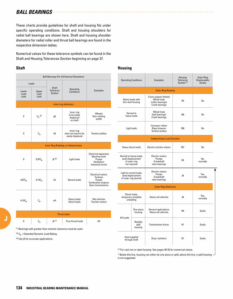
These charts provide guidelines for shaft and housing fits under specific operating conditions. Shaft and housing shoulders for radial ball bearings are shown here. Shaft and housing shoulder diameters for radial roller and thrust ball bearings are found in the respective dimension tables.
Numerical values for these tolerance symbols can be found in the Shaft and Housing Tolerances Section beginning on page 37.
Shaft
Ball Bearings (For All Nominal Diameters)
Loads
ShaftTolerance
Symbol
Operating Conditions ExamplesLower
Load Limit
Upper Load Limit
Inner ring stationary
0 Ce (2) g6
Inner ringto be easilydisplacedon shaft
WheelsNon-rotating
shafts
0 Ce h6Inner ring
does not need to beeasily displaced
Tension pulleys
Inner Ring Rotating, or Indeterminate
0 0.07Ce j6 (3) Light loads
Electrical apparatusMachine tools
PumpsVentilators
Industrial trucks
0.07Ce 0.15Ce k5 Normal loads
Electrical motorsTurbinesPumps
Combustion enginesGear transmissions
0.15Ce Ce m5 Heavy loadsShock loads
Rail vehiclesTraction motors
Thrust loads
0 Ce j6 (1) Pure thrust loads All
Housing
Operating Conditions ExamplesHousing
ToleranceSymbol (1)
Outer RingDisplaceable
Axially
Outer Ring Rotating
Heavy loads withthin-wall housing
Crane support wheelsWheel hubs
(roller bearings)Crank bearings
P6 No
Normal toheavy loads
Wheel hubs(ball bearings)Crank bearings
N6 No
Light loadsConveyor rollers
Rope sheavesTension pulleys
M6 No
Indeterminate Load Direction
Heavy shock loads Electric traction motors M7 No
Normal to heavy loads, axial displacement
of outer ringnot required
Electric motorsPumps
Crankshaftmain bearings
K6 No,normally
Light to normal loads,axial displacement
of outer ring desired
Electric motorsPumps
Crankshaftmain bearings
J6 Yes,normally
Outer Ring Stationary
Shock loads,temporary complete
unloadingHeavy rail vehicles J6 Yes,
normally
All Loads
One-piece housing
General applications Heavy rail vehicles H6 Easily
Radiallysplit
housingTransmission drives H7 Easily
Heat suppliedthrough shaft Dryer cylinders G7 Easily
(1) Bearings with greater than nominal clearance must be used.
(2) Ce = Extended Dynamic Load Rating.
(3) Use j5 for accurate applications.
(1) For cast iron or steel housing. See pages 46-53 for numerical values.
* Below this line, housing can either be one piece or split; above this line, a split housing is not suggested.
BALL BEARINGS
INDUSTRIAL BEARING MAINTENANCE MANUAL134
J

Shaft and housing shoulders - extra small series
These tables give the suggested maximum and minimum shaft and housing shoulder diameters for most applications. Where design limitations do not permit conformance to the suggested diameters, contact your Timken representative.
BasicBearingNumber
Shoulder Diameters
Shaft, S Housing, H
Max. Min. Max. Min.
mmin.
mmin.
33K3 5 .10.20
4 .80.19
8 .10.32
7 .90.31
33K4 6 .10.24
5 .80.23
11 .20.44
10 .90.43
33K5 6 .60.26
6 .40.25
11 .20.44
10 .90.43
34K 6 .60.26
6 .40.25
14 .20.56
14 .00.55
35K 9 .40.37
9 .10.36
17 .00.67
16 .80.66
36K 9 .40.37
9 .10.36
17 .00.67
16 .80.66
37K 11 .20.44
10 .70.42
20 .10.79
19 .60.77
38K 11 .40.45
10 .90.43
20 .10.79
19 .60.77
38KV 11 .40.45
10 .90.43
20 .10.79
19 .60.77
39K 13 .00.51
12 .50.49
23 .10.91
22 .60.89
S1K7 8 .60.34
8 .10.32
14 .20.56
13 .70.54
S1K 9 .40.37
8 .90.35
17 .50.69
17 .00.67
S3K 12 .70.50
12 .20.48
20 .30.80
19 .80.78
S5K 16 .00.63
15 .50.61
25 .10.99
24 .60.97
S7K 21 .30.84
20 .30.80
31 .51.24
30 .51.20
S8K 24 .60.97
23 .60.93
37 .11.46
35 .61.40
S9K 28 .91.14
27 .91.10
41 .91.65
40 .91.61
S10K 31 .51.24
30 .51.20
46 .71.84
45 .71.80
S11K 34 .01.34
33 .01.30
49 .51.95
48 .51.91
S12K 39 .41.55
38 .41.51
55 .92.20
50 .82.00
BasicBearingNumber
Shaft Shoulder±0 .25 mm±.010 in.
Housing Shoulder±0 .25 mm±.010 in.
mmin.
mmin.
9301K 14 .70.58
21 .60.85
9302K 17 .80.70
25 .41.00
9303K 19 .80.78
27 .41.08
9304K 23 .90.94
33 .51.32
9305K 29 .01.14
38 .61.52
9306K 33 .51.32
43 .41.71
9307K 39 .61.56
50 .82.00
9308K 45 .01.77
57 .42.26
9309K 50 .31.98
63 .22.49
9310K 54 .92.16
67 .62.66
9311K 61 .02.40
74 .72.94
9312K 65 .82.59
79 .83.14
Extra light 9300 extra-small series Extra-small series
S H
Fig . 45 . Extra small series .
Shaft and housing diameters for radial ball bearings are shown here. Diameters for cylindrical, spherical and tapered roller bearings are found in the respective dimension tables.
Housing shoulders for wide inner ring bearings are shown on page 140.
BALL BEARINGS
INDUSTRIAL BEARING MAINTENANCE MANUAL 135
J

Shaft and housing shoulders - radial ball bearings
Extra-Light - 9100 Series Light - 200, 5200, 7200WN Series Medium - 300, 5300, 7300WN Series
BasicBearingNumber
Shoulder Diameters
BasicBearingNumber
Shoulder Diameters
BasicBearingNumber
Shoulder Diameters
Shaft, S Housing, H Shaft, S Housing, H Shaft, S Housing, H
Max. Min. Max. Min. Max. Min. Max. Min. Max. Min. Max. Min.
mmin.
mmin.
mmin.
mmin.
mmin.
mmin.
9100 13 .200.52
11 .900.47
24 .100.95
23 .100.91 200 14 .20
0.5612 .700.50
24 .900.98
24 .600.97 300 15 .00
0.5912 .700.50
30 .001.18
29 .201.15
9101 18 .000.71
14 .000.55
25 .901.02
24 .600.97 201 16 .30
0.6414 .700.58
26 .901.06
26 .701.05 301 17 .50
0.6916 .000.63
31 .001.22
30 .701.21
9102 19 .000.75
17 .000.67
30 .001.18
28 .701.13 202 19 .00
0.7517 .500.69
30 .001.18
29 .201.15 302 20 .60
0.8119 .000.75
36 .101.42
35 .601.40
9103 20 .600.81
19 .000.75
33 .001.30
31 .801.25 203 21 .30
0.8419 .600.77
34 .001.34
33 .301.31 303 23 .10
0.9121 .100.83
40 .901.61
40 .601.60
9104 24 .900.98
22 .600.89
37 .101.46
35 .801.41 204 25 .40
1.0023 .900.94
40 .901.61
40 .101.58 304 26 .90
1.0623 .900.94
45 .001.77
44 .401.75
9105 30 .001.18
27 .401.08
41 .901.65
40 .601.60 205 31 .00
1.2229 .001.14
46 .001.81
45 .201.78 305 33 .30
1.3129 .001.14
55 .102.17
53 .102.09
9106 35 .101.38
34 .001.34
49 .001.93
47 .801.88 206 37 .30
1.4734 .001.34
56 .102.21
54 .902.16 306 39 .60
1.5634 .001.34
65 .002.56
62 .002.44
9107 41 .401.63
38 .901.53
56 .102.21
54 .602.15 207 43 .70
1.7238 .901.53
65 .002.56
62 .702.47 307 45 .20
1.7842 .901.69
71 .102.80
69 .102.72
9108 46 .001.81
43 .901.73
62 .002.44
60 .702.39 208 49 .30
1.9443 .901.73
72 .902.87
70 .602.78 308 50 .80
2.0049 .001.93
81 .003.19
77 .703.06
9109 51 .602.03
49 .301.94
69 .102.72
67 .802.67 209 54 .10
2.1349 .301.94
78 .003.07
75 .402.97 309 2 .28
57.902 .1354.10
3 .5890.90
3 .4186.60
9110 56 .402.22
54 .102.13
73 .902.91
72 .602.86 210 59 .40
2.3454 .102.13
83 .103.27
80 .503.17 310 63 .50
2.5059 .902.36
100 .103.94
95 .203.75
9111 63 .002.48
59 .202.33
83 .103.27
81 .803.22 211 64 .50
2.5461 .202.41
93 .503.68
90 .403.56 311 69 .80
2.7565 .002.56
110 .004.33
104 .904.13
9112 67 .802.67
64 .302.53
88 .103.47
86 .903.42 212 71 .40
2.8167 .802.67
101 .103.98
98 .303.87 312 74 .70
2.9472 .102.84
118 .104.65
112 .804.44
9113 72 .102.84
69 .102.72
93 .003.66
81 .703.61 213 77 .00
3.0372 .602.86
111 .004.37
106 .404.19 313 81 .00
3.1977 .003.03
128 .005.04
122 .204.81
9114 79 .003.11
73 .902.91
103 .104.06
100 .803.97 214 81 .80
3.2277 .703.06
116 .104.57
112 .004.41 314 87 .40
3.4482 .003.23
137 .905.43
130 .305.13
9115 84 .103.31
79 .003.11
108 .004.25
105 .704.16 215 87 .40
3.4482 .603.25
120 .904.76
116 .604.59 315 98 .60
3.8887 .103.43
148 .105.83
139 .705.50
9116 90 .403.56
84 .103.31
118 .104.65
114 .304.50 216 93 .70
3.6990 .203.55
130 .005.12
125 .204.93 316 100 .10
3.9491 .903.62
158 .006.22
149 .405.88
9117 95 .203.75
88 .903.50
122 .904.84
119 .604.71 217 98 .60
3.8895 .203.75
140 .005.51
134 .905.31 317 104 .90
4.1399 .103.90
166 .106.54
157 .206.19
S H
Fig . 46 . Radial ball bearing .
BALL BEARINGS
INDUSTRIAL BEARING MAINTENANCE MANUAL136
J

Extra-Light - 9100 Series Light - 200, 5200, 7200WN Series Medium - 300, 5300, 7300WN Series
BasicBearingNumber
Shoulder Diameters
BasicBearingNumber
Shoulder Diameters
BasicBearingNumber
Shoulder Diameters
Shaft, S Housing, H Shaft, S Housing, H Shaft, S Housing, H
Max. Min. Max. Min. Max. Min. Max. Min. Max. Min. Max. Min.
mmin.
mmin.
mmin.
mmin.
mmin.
mmin.
9118 102 .404.03
97 .503.84
131 .105.16
130 .305.13 218 105 .70
4.16100 .103.94
150 .105.91
142 .705.62 318 111 .30
4.38103 .904.09
176 .006.93
165 .106.50
9120 111 .304.38
107 .404.23
141 .005.55
138 .205.44 219 111 .30
4.38106 .904.21
158 .006.22
153 .906.06 319 117 .60
4.63109 .004.29
185 .907.32
174 .806.88
9121 118 .404.66
115 .104.53
150 .105.91
146 .005.75 220 117 .60
4.63112 .004.41
167 .906.61
160 .306.31 320 124 .00
4.88114 .004.49
200 .907.91
187 .407.38
9122 124 .704.91
119 .904.72
160 .006.30
157 .006.18 221 124 .00
4.88117 .104.61
178 .107.01
174 .806.88 321 130 .30
5.13119 .104.69
211 .108.31
196 .807.75
9124 134 .105.28
130 .005.12
169 .906.69
165 .106.50 222 130 .30
5.13121 .904.80
188 .007.40
179 .307.06 322 139 .70
5.50124 .004.88
226 .108.90
209 .608.25
9126 147 .605.81
140 .005.51
190 .007.48
184 .107.25 224 143 .00
5.63132 .105.20
202 .907.99
192 .007.56 324 152 .40
6.00134 .105.28
246 .109.69
226 .808.93
9128 153 .906.06
147 .605.81
200 .207.88
195 .107.68 226 152 .40
6.00144 .005.67
215 .908.50
206 .508.13 326 163 .60
6.44148 .105.83
262 .1010.32
246 .109.69
9130 167 .406.59
162 .106.38
213 .108.39
206 .508.13 228 165 .10
6.50153 .906.06
236 .009.29
223 .808.81 328 176 .00
6.93158 .006.22
281 .9011.10
263 .7010.38
9132 176 .806.96
166 .606.56
228 .609.00
222 .208.75 230 177 .00
6.97164 .106.46
256 .0010.08
241 .309.50 330 189 .00
7.44167 .906.61
302 .0011.89
280 .9011.06
9134 192 .007.56
182 .107.17
247 .909.76
239 .809.44 232 186 .90
7.36174 .006.85
276 .1010.87
260 .4010.25 332 188 .00
7.84178 .007.01
322 .1012.68
294 .1011.58
9138 212 .908.38
201 .907.95
278 .1010.95
266 .7010.50 234 202 .70
7.98188 .007.40
292 .1011.50
276 .4010.88 334 213 .40
8.40188 .007.40
342 .1013.47
311 .7012.27
9140 224 .508.84
212 .108.35
297 .9011.73
285 .0011.22 236 212 .90
8.38198 .107.80
302 .0011.89
281 .7011.09 336 223 .50
8.80198 .107.80
362 .0014.25
331 .5013.05
9144 246 .409.70
233 .909.21
326 .1012.84
310 .9012.24 238 222 .80
8.77208 .008.19
322 .1012.68
301 .8011.88 338 237 .50
9.35212 .108.35
378 .2014.89
345 .2013.59
9148 266 .7010.50
254 .0010.00
345 .9013.62
330 .7013.02 240 239 .30
9.42217 .908.58
342 .1013.47
319 .3012.57 340 249 .90
9.84222 .008.74
398 .0015.67
365 .0014.37
9152 291 .801 1.49
278 .1010.95
382 .0015.04
366 .8014.44 242 246 .10
9.69225 .308.87
362 .2014.26
336 .8013.26 342 260 .10
10.24232 .209.14
418 .3016.47
385 .3015.17
9156 313 .2012.33
297 .9011.73
402 .1015.83
386 .8015.23 244 257 .60
10.14238 .009.37
382 .0015.04
356 .6014.04 344 272 .50
10.73242 .109.53
437 .9017.24
405 .4015.96
9160 339 .301 3.36
318 .0012.52
442 .0017.40
421 .6016.60 246 268 .70
10.58247 .909.76
402 .1015.83
370 .8014.60 348 292 .60
11.52262 .1010.32
478 .0018.82
439 .9017.32
9164 360 .4014.19
338 .1013.31
462 .0018.19
441 .7017.39 248 283 .50
11.16258 .1010.16
421 .9016.61
385 .6015.18 352 318 .50
12.54288 .0011.34
512 .1020.16
474 .0018.66
9180 457 .2018.00
431 .8017.00
561 .8022.12
549 .1021.62 250 293 .40
11.55268 .0010.55
442 .0017.40
398 .8015.70 356 341 .10
13.43308 .1012.13
551 .9021.73
511 .3020.13
BALL BEARINGS
INDUSTRIAL BEARING MAINTENANCE MANUAL 137
J

Basic Bearing Number
Shaft, S Housing, H
Max. Min. Max. Min.
mm in.
mm in.
7405 37 .31.47
34 .01.34
71 .12.80
66 .82.63
7406 43 .71.72
39 .11.54
81 .03.19
76 .23.00
7407 49 .01.93
43 .91.73
90 .93.58
85 .93.38
7408 55 .62.19
50 .01.97
100 .13.94
93 .73.69
7409 62 .02.44
55 .12.17
110 .04.33
101 .64.00
7410 68 .32.69
62 .02.44
118 .14.65
111 .34.38
7411 74 .42.93
67 .12.64
128 .05.04
120 .74.75
7412 81 .03.19
72 .12.84
137 .95.43
130 .35.13
7413 88 .93.50
77 .03.03
148 .15.83
139 .75.50
7414 93 .73.69
84 .13.31
166 .16.54
155 .76.13
7415 99 .83.93
88 .93.50
176 .06.93
163 .66.44
7416 104 .94.13
94 .03.70
185 .97.32
173 .06.81
7418 119 .14.69
108 .04.25
207 .08.15
196 .97.75
7420 131 .35.17
119 .94.72
233 .99.21
223 .38.79
Basic Bearing Number
Shoulder Diameters
Shaft, S Housing, H
Max. Min. Max. Min.
mmin.
mmin.
120W2 117 .6 4.63
111 .8 4.40
150 .1 5.91
146 .05.75
122W 124 .7 4.91
120 .1 4.73
162 .8 6.41
158 .8 6.25
124W 134 .1 5.28
130 .0 5.12
178 .1 7.01
174 .5 6.87
126W 147 .8 5.82
139 .7 5.50
193 .0 7.60
185 .7 7.31
128W 157 .2 6.19
150 .1 5.91
207 .8 8.18
202 .2 7.96
130W 167 .4 6.59
162 .1 6.38
223 .0 8.78
216 .2 8.51
132W 189 .0 7.44
174 .0 6.85
234 .7 9.24
223 .8 8.81
134W 191 .0 7.52
185 .2 7.29
249 .7 9.83
244 .1 9.61
136W 203 .2 8.00
195 .3 7.69
264 .7 10.42
257 .8 10.15
138W 214 .4 8.44
205 .2 8.08
284 .7 11.21
276 .1 10.87
224W 143 .0 5.63
132 .1 5.20
203 .2 8.00
192 .0 7.56
226 152 .4 6.00
144 .0 5.67
215 .9 8.50
206 .5 8.13
228 165 .1 6.50
153 .9 6.06
236 .0 9.29
223 .8 8.81
276–2 401 .8 15.82
400 .1 15.75
463 .6 18.25
461 .5 18.17
Shaft and housing shoulder
Heavy 400, 7400 series Non-standard extra-large
S H
Non Standard Extra-LargeFig . 47 . Non standard extra large .
BALL BEARINGS
INDUSTRIAL BEARING MAINTENANCE MANUAL138
J

Basic Bearing Number
Housing Shoulder Diameter, H
Max. Min.
mm in.
mmin.
36 17 .0 0.67
16 .8 0.66
36V 17 .0 0.67
16 .8 0.66
37 20 .1 0.79
19 .6 0.77
37V 20 .1 0.79
19 .6 0.77
34 20 .1 0.79
19 .6 0.77
38V 20 .1 0.79
19 .6 0.77
39 23 .1 0.91
22 .6 0.89
39V 23 .1 0.91
22 .6 0.89
200 27 .7 1.09
26 .2 1.03
201 29 .5 1.16
27 .7 1.09
20-2 29 .5 1.16
27 .7 1.09
201-3 29 .5 1.16
27 .7 1.09
202 32 .5 1.28
31 .0 1.22
202-2 32 .5 1.28
31 .0 1.22
202-3 32 .5 1.28
31 .0 1.22
202-4 32 .5 1.28
31 .0 1.22
203 36 .6 1.44
35 .8 1.41
204 43 .7 1.72
41 .1 1.62
204-2 43 .7 1.72
41 .1 1.62
205 48 .5 1.91
46 .7 1.84
205-2 48 .5 1.91
46 .7 1.84
206 57 .9 2.28
56 .4 2.22
207 67 .6 2.66
64 .3 2.53
208 75 .4 2.97
71 .4 2.81
209 80 .3 3.16
77 .0 3.03
209-2 80 .3 3.16
77 .0 3.03
211 93 .7 3.69
90 .4 3.56
Shaft and housing shoulder
Mechani-Seal KL, KLD, KLL types
Housing shoulder diameters of bearings with Mechani-Seals differ slightly from those of other types to allow for clearance between the external rotating member of the seal and the housing shoulder.
Fig . 48 . Mechani-Seal KL, KLD, KLL types .
Dd
C
BALL BEARINGS
INDUSTRIAL BEARING MAINTENANCE MANUAL 139
J

Bearing NumberShaftSize Basic
Outer RingSize
Housing Stationary (1)
Shoulder Diameter, H
KRRType
G-KRRType
RA-RRType
GRA-RRType
GYA-RR (2)
Type
Housing Bore, D Mean Fit
Max. Min. Loose Max. Min.
mmin.
mmin.
mmin.
mmin.
mmin.
mmin.
1008KRR — RA008RR GRA008RR GYA0008RR 1⁄2
203 40 .0151.5754
40 .0001.5748
0 .0130.0005
34 .81.37
34 .01.34
— — RA009RR GRA009RR GYA009RR 9⁄16
1010KRR(KR) G1010KRR RA010RR GRA010RR GYA010RR 5⁄8
1011KRR G1011KRR — — — 11⁄16
E17KRR GE17KRR RAE17RR GRAE17RR GYAE17RR 17
1012KRR(KR) G1012KRR RA012RR GRA012RR GYA012RR 3⁄4204 47 .015
1.851047 .0001.8504
0 .0130.0005
40 .91.61
40 .61.60E20KRR GE20KRR RAE20RR GRAE20RR GYAE20RR 20
1013KRR — RA013RR GRA013RR GYA013RR 13⁄16
205 52 .0172.0479
51 .9992.0472
0 .0150.0006
46 .01.81
45 .71.80
1014KRR G1014KRR RA014RR GRA014RR GYA014RR 7⁄8
1015KRR(KR) G1015KRR RA015RR GRA015RR GYA015RR 15⁄16
1100KRR(KR) G1100KRR RA100RR GRA100RR GYA100RR 1
E25KRR GE25KRR RAE25RR GRAE25RR GYAE25RR 25
— G1101KRR RA101RR GRA101RR GYA101RR 1 1⁄16
206 62 .0172.4416
61 .9992.4409
0 .0150.0006
56 .12.21
54 .92.16
1102KRR(KR) G1102KRR RA102RR GRA102RR GYA102RR 1 1⁄8
1103KRR(KR) G1103KRR RA103RR GRA103RR GYA103RR 1 3⁄16
— — — — GYA103RR2 1 1⁄4
E30KRR GE30KRR RAE30RR GRAE30RR GYAE30RR 30
Housing, shoulders and shaft diameters
(1) When the housing revolves in relation to the shaft, housing bore dimensions shown on pages 130-133 should be used. Outer ring tolerances and housing fillet radii correspond to equivalent 200 Series single row radial bearings.
(2) Available as non-relubricatable type (omit Prefix “G”).
Shaft and housing considerations
When selecting shafts for use with wide inner ring bearings, a minimum slip fit is desirable for the most satisfactory mounting. Special shaft limits are required in certain cases, and a variety of standard fits can be used, even including a press fit.
The suggested figures are noted below, but in some applications it may be permissible to use increased shaft tolerances. Contact your Timken representative for recommendations.
Bearing bore tolerance1/2 in. - 2 3/16 in. = nominal to +.013 mm (+.0005 in.)
2 1/4 in. - 3 3/16 in. = nominal to +.015 mm (+.0006 in.)
3 7/16 in. - 3 15/16 in. = nominal to +.018 mm (+.0007 in.)
Suggested shaft tolerances1/2 in. - 1 15/16 in. = nominal to -.013 mm (-.0005 in.)
2 in. - 3 15/16 in. = nominal to -.025 mm (-.0010 in.)
H D
Fig . 49 . Wide inner ring ball bearing .
Continued on next page.
BALL BEARINGS
INDUSTRIAL BEARING MAINTENANCE MANUAL140
J

Bearing NumberShaftSize Basic
Outer RingSize
Housing Stationary (1)
Shoulder Diameter, H
KRRType
G-KRRType
RA-RRType
GRA-RRType
GYA-RR (2)
Type
Housing Bore, D Mean Fit
Max. Min. Loose Max. Min.
mmin.
mmin.
mmin.
mmin.
mmin.
mmin.
1104KRR(KR) G1104KRR RA104RR GRA104RR GYA104RR 1 1⁄4
207 72 .0172.8353
71 .9992.8346
0 .0150.0006
56 .12.56
54 .92.47
1105KRR — RA105RR GRA105RR GYA105RR 1 5⁄16
1106KRR G1106KRR RA106RR GRA106RR GYA106RR 1 3⁄8
1107KRR(KR) G1107KR RRA107RR GRA107RR GYA107RR 1 7⁄16
E35KRR GE35KRR RAE35RR GRAE35RR GYAE35RR 35
1108KRR(KR) G1108KRR RA108RR GRA108RR GYA108RR 1 1⁄2
208 80 .0183.1503
80 .0003.1496
0 .0200.0006
78 .02.87
75 .42.78— — RA106RR GRA109RR GYA109RR 1 9⁄16
— — — GRAE40RR GYAE40RR 40
1110KRR G1110KRR RA110RR GRA110RR GYA110RR 1 5⁄8
209 85 .0243.3474
85 .0013.3465
0 .0200.0008
78 .03.07
75 .42.97
1111KRR(KR) G1111KRR RA111RR GRA111RR GYA111RR 1 11⁄16
1112KRR(KR) G1112KRR RA112RR GRA112RR GYA112RR 1 3⁄4
E45KRR — — GRAE45RR GYAE45RR 45
— — RA113RR GRA113RR GYA113RR 1 13⁄16
210 90 .0233.5442
90 .0003.5433
0 .0200.0008
83 .13.27
81 .03.19
1114KRR — RA114RR GRA114RR GYA114RR 1 7⁄8
1115KRR(KR) G1115KRR RA115RR GRA115RR GYA115RR 1 15⁄16
— — — GRA115RR2 — 2
E50KRR GE50KRR RAE50RR GRAE50RR GYAE50RR 50
1200KRR(KR) G1200KRR RA200RR GRA200RR GYA200RR 2
211 100 .0233.9379
100 .0003.9370
0 .0200.0008
90 .93.58
90 .43.56
— — RA201RR GRA201RR GYA201RR 2 1⁄16
1202KRR — RA202RR GRA202RR GYA202RR 2 1⁄8
1203KRR(KR) G1203KRR RA203RR GRA203RR GYA203RR 2 3⁄16
E55KRR GE55KRR RAE55RR GRAE55RR GYAE55RR 55
1204KRR — — — — 2 1⁄4
212 110 .024.3316
110 .0004.3307
0 .0200.0008
101 .13.98
98 .33.871207KRR(KR) G1207KRR — — — 2 7⁄16
E60KRR GE60KRR — — — 60
1215KRR — — — — 2 15⁄16215 130 .025
5.1191130 .0005.1181
0 .0230.0009
120 .94.76
116 .64.59E75KRR — — — — 75
Housing, shoulders and shaft diameters
(1) When the housing revolves in relation to the shaft, housing bore dimensions shown on pages 130-133 should be used. Outer ring tolerances and housing fillet radii correspond to equivalent 200 Series single row radial bearings.
(2) Available as non-relubricatable type (omit Prefix “G”).
BALL BEARINGS
INDUSTRIAL BEARING MAINTENANCE MANUAL 141
J

MAINTENANCE TOOLS
BALL BEARINGS
INDUSTRIAL BEARING MAINTENANCE MANUAL142
J

MAINTENANCE TOOLSK MAINTENANCE TOOLS
Maintenance Tools . . . . . . . . . . . . . . . . . . . . . . . . . . . . . . . . . . . . 145
Mounting Tools . . . . . . . . . . . . . . . . . . . . . . . . . . . . . . . . . . . . . . . . 145
K
KK

MAIN
TENANCE TOOLS
K KK

MAIN
TENANCE TOOLS
MAINTENANCE TOOLSConvenient handling devices give technicians the tools they need to properly and more easily install, remove and service bearings, which is essential to ensure long bearing life and may prevent unnecessary damage. Timken products available to help customers safely handle bearings include impact fitting tools, induction heaters, and mechanical, hydraulic and self-centering pullers. Impact tools are used to forcefully drive bearing components on or off shafts, or in or out of housings. Timken induction heaters can be used for heating gear wheels, bushings, couplings and other components to aid installation. Pullers are ideal for removing all kinds of shaft-fitted parts easily.
MOUNTING TOOLS
Removing and installing bearings can be made easier using a variety of installation tools. This is especially true for bearings installed with tight or interference fits that can be difficult to install and remove.
Induction heaters
Induction heaters provide a fast, controlled heating method that does not create the smoke, fumes or oil waste caused when using other methods. This makes induction heaters a more environmentally friendly method.
These heaters come in various sizes, and a heater may also come with different sized yokes. Choose a yoke size that fills the bore of the bearing as fully as possible. You can also combine two yokes to heat the bearing more quickly and evenly (Fig. 50).
Induction heaters work very quickly. Take care to avoid heating the bearing with seals to temperatures higher than 90ºC (200ºF). Consult your induction heater manual for proper temperature and time setting guidelines. Trial runs with the induction heater and bearings are generally necessary to determine the proper timing. Thermal crayons that melt at predetermined temperatures can be used to monitor the bearing temperature.
Place the heater probe as close as possible to the bore of the of the work piece. Ensure that the area where the probe is located is completely clean. Handle the probe with care. It is a valuable part of the heater and can easily break.
Ensure that the heating and demagnetization cycle is complete before removing the work piece.
Fig . 50 . Two yokes can be combined to heat the bearing bore .
CAUTION Failure to observe the followingcautions could create a risk of injury:
If the bearing is to be reused or returned for repair, do not use heat from a torch.
Extreme heat from a torch can alter the bearing hardness and metallurgical structure, resulting in irreparable damage.
MAINTENANCE TOOLS
INDUSTRIAL BEARING MAINTENANCE MANUAL 145
KK

Impact tools
Impact tools are used to forcefully drive bearing components on or off shafts, or in or out of housings. It is not recommended that they be used with bearing assemblies. The tools should be made of materials that will not nick or damage shafts and housings. These materials may include soft metals or impact resistant plastic.
When using impact tools, use caution to avoid missed strikes that allow the hammer to come into contact with the shaft or housing.
Hydraulic nuts
Hydraulic nuts can be used to speed and ease the installation and removal of tapered bore bearings. The pressure generated by the piston creates a smooth, controllable force to enable precise positioning of the bearing on the shaft. These nuts provide better control of the bearing internal clearance reduction, while reducing the chance of damaging the bearing or other components.
Pullers
There are a variety of hand and hydraulic pullers (Fig. 51 and 52) available that can be used to pull bearings, bushings, gear wheels, couplings or other press-fitted work pieces. Hydraulic pulling devices can usually apply more force than hand pullers.
When using hydraulic or hand pullers:
• Select the proper size and capacity puller for the job.
• Make sure the puller capacity exceeds calculated maximum withdrawal forces.
• Ensure the puller legs are properly secured around the work piece. Each leg must be fully engaged.
• Always apply force gradually.
• On hand pullers, do not use a hammer when operating the spindle.
Fig . 52 . Puller .
Fig . 51 . Puller .
LUBRICATION AND SEALS
MAINTENANCE TOOLS
INDUSTRIAL BEARING MAINTENANCE MANUAL146
KK

LUBRICATION AND SEALSL LUBRICATION AND SEALS
Lubrication . . . . . . . . . . . . . . . . . . . . . . . . . . . . . . . . . . . . . . . . . . . . 149
Oils . . . . . . . . . . . . . . . . . . . . . . . . . . . . . . . . . . . . . . . . . . . . . . . . . . . 149
Grease Lubrication . . . . . . . . . . . . . . . . . . . . . . . . . . . . . . . . . . . . . 151
Grease Selection . . . . . . . . . . . . . . . . . . . . . . . . . . . . . . . . . . . . . . 153
Special Applications . . . . . . . . . . . . . . . . . . . . . . . . . . . . . . . . . . . 154
Seals . . . . . . . . . . . . . . . . . . . . . . . . . . . . . . . . . . . . . . . . . . . . . . . . . 158
Installation Methods . . . . . . . . . . . . . . . . . . . . . . . . . . . . . . . . . . . 159
L
KK
L

LUBRIC
ATION AND SEALS
LLL

LUBRIC
ATION AND SEALS
LLUBRICATIONUsing our knowledge of tribology, anti-friction bearings and total system performance needs, Timken has developed a complete line of application- and environment-specific lubricants.
Timken offers a range of lubricants to help bearings and related components operate effectively in demanding industrial operations. High-temperature, anti-wear and water-resistant additives offer greater protection in challenging environments. Timken also offers a line of single- and multi-point lubricators to simplify the delivery of grease.
Most bearings used in general industrial and precision applications do not reach their fatigue life goal for a variety of reasons. Proper lubrication is essential to achieve optimum equipment performance, minimum equipment downtime and the longest possible bearing life.
When a properly lubricated bearing rotates, the mating surfaces of the bearing components create a lubricant film that keeps the components separated. The lubricant:
• Provides a suitable film that prevents metal-to-metal contact and separates the moving parts in a bearing
• Carries away heat
• Protects the bearing surfaces from corrosion
In some cases, the lubricant can also trap debris, carrying it away from the contact surfaces.
The correct lubricant for each application depends on the bearing design and the operating conditions. The wide range of bearing types and operating conditions precludes any simple, all-inclusive guidelines regarding lubricant selection and use. However, an understanding of the characteristics and advantages of the various lubricants available can be helpful in implementing appropriate lubrication-related maintenance.
The lubrication requirements of all Timken bearings used in general industrial applications can be met with high quality petroleum lubricants. However, synthetic lubricants are gaining considerable popularity, especially where high operating temperatures and long service life is required.
New Timken bearings are protected with a preservative coating. The preservative coating is compatible with most lubricants, so it is not necessary to wash it off prior to installation. Bearings that are not pre-lubricated, however, will require proper lubrication as part of the installation process.
Lubricant types can be broadly divided into two groups; oil or grease. Each has its advantages (Table 4).
Oil Grease
Carries heat away from the bearings Simplifies seal design and acts as a sealant
Carries away moistureand particular matter
Permits prelubrication of sealedor shielded bearings
Easily controlled lubrication Generally requires less frequent lubrication
Table 4 . Advantages of oil and grease .
OILS
Oil Types
Oils are classified as either petroleum or synthetic. Petroleum oils are refined from crude oil and synthetic oils are produced by chemical synthesis.
The primary characteristic when selecting an oil is its viscosity, a measure of its flow characteristics. Viscosity is normally expressed in terms of the time required for a specific amount of oil to flow through a standard size hole at a specific temperature. Viscosity varies with temperature and is always described with the temperature at which it was measured.
The International System (S.I. units) for classifying viscosity uses centistokes at standard temperatures of 40ºC (104ºF) and 100ºC (212ºF). The Saybolt Universal Second (SUS) is also commonly used in many parts of the world. The standard measuring temperature for SUS is 40°C (100ºF) and 100°C (210ºF).
There are many classifications for oil viscosity grades. The most familiar is the Society of Automotive Engineers (SAE) system, which includes automotive engine and gear oils for conventional crankcases (Fig. 53) and manual transmission oils (Fig. 54).
The American Society of Testing and Materials (ASTM) has adopted a standard of viscosity grades for industrial fluids, known as the ISO viscosity grade. This system shows the viscosity grade as the numerical viscosity of the fluid in centistokes at 40ºC (104°F) (Fig. 55). These two viscosity classification systems can be directly compared (Fig. 56).
When selecting the correct oil for an application, the bearing size, speed, temperature, load and general operating condition must all be considered. Consult with your lubricant supplier or equipment manufacturer for specific questions about lubrication requirements for a piece of equipment. You can also contact your Timken representative for general lubrication guidelines for any application.
LUBRICATION AND SEALS
INDUSTRIAL BEARING MAINTENANCE MANUAL 149
LL

500000100000
20000
5000
1000500
200
100
50
20
10
5.004.00
3.00
2.00
1.50
1.00
20000050000
100005000
20001000
500
200
10075
50
40
35
33
SAE Crankcase OilViscosity ClassificationSAE J300-80Assumes 110 Viscosity Index
504030
20
10W min.5W min.
0 50 100 150
Temperature Degrees Celcius
Temperature Degrees Fahrenheit
20 60 100 140 180 220 260 300
210
Kine
mat
ic V
isco
sity
, Cen
tisto
kes
(cSt
)
Visc
osity
, Say
bolt
Univ
ersa
l Sec
onds
(SUS
)
500000100000
20000
5000
1000500
200
100
50
20
10
5.004.00
3.00
2.00
1.50
1.00
20000050000
100005000
20001000
500
200
10075
50
40
35
33
SAE Axle & Manual TransmissionLubricant Viscosity ClassificationSAE J306-81Assumes 90 Viscosity Index
0 50 100 150
Temperature Degrees Celcius
Temperature Degrees Fahrenheit
20 60 100 140 180 220 260 300
210
Kine
mat
ic V
isco
sity
, Cen
tisto
kes
(cSt
)
Visc
osity
, Say
bolt
Univ
ersa
l Sec
onds
(SUS
)
140
90
85W min.
80W min.
70W min.
250 min.
500000100000
20000
5000
1000500
200
100
50
20
10
5.004.00
3.00
2.00
1.50
1.00
20000050000
100005000
20001000
500
200
10075
50
40
35
33
ISO/ASTM Viscosity SystemFor Industrial Fluid LubricantsISO 3448ASTM D2422Assumes 90 Viscosity Index
0 50 100 150
Temperature Degrees Celcius
Temperature Degrees Fahrenheit
20 60 100 140 180 220 260 300
210
Kine
mat
ic V
isco
sity
, Cen
tisto
kes
(cSt
)
Visc
osity
, Say
bolt
Univ
ersa
l Sec
onds
(SUS
)
ISO/ASTM Grade Designations
ISO/ASTM Viscosity RangeViscosity Grade cSt (mm2/s) at 40ºC*
1500 1350-1650 1000 900-1100 680 612-748 460 414-506 320 288-352 220 198-242 150 135-165 100 90-110 68 61-75 46 41-51 32 29-35 22 20-24
*Rounded off to the nearestwhole number
680460320220150100684632
ISO VG
2000
1500
1000800
600
400
300
200150
10080
60
4030
20
15
108
6
4
3
2
1500
1000
680
460
320
220
150
20
30
40
50
140
90
100
68
46
32
22
15
10
7
5
3
2
ISO/ASTMViscosity Grade
SAE Crankcase Oils
Viscosity Classification Comparison
SAE Gear Oil
10W min.
5W min.
250 min.
85W min.
80W min.
70W min.
10000
7500
50004000
3000
2000
1500
1000
700
500400
300
200
150
100
75
60
50
40
3533
Kine
mat
ic V
isco
sity
, Cen
tisto
kes
(cSt
) at 4
0ºC
Visc
osity
, Say
bolt
Univ
ersa
l Sec
onds
(SUS
) at 1
00ºF
Fig . 53 . Automotive engine and gear oils .
Fig . 56 . Comparison of viscosity systems .Fig . 55 . ISO Viscosity system .
Fig . 54 . Manual transmission oils .
LUBRICATION AND SEALS
INDUSTRIAL BEARING MAINTENANCE MANUAL150
LL

Oil advantages
Where heat must be carried away from the bearing, oil must be used, and it is nearly always preferred for very high-speed applications. Other relevant features and advantages of oil lubrication include:
• Oil is a better lubricant for high speeds or high temperatures, and can be cooled to help reduce bearing temperature.
• Oil is easier to handle and to control the amount of lubricant reaching the bearing, but it is harder to retain in the bearing. Lubricant losses may be higher than with grease.
• As a liquid, oil can be introduced to the bearing in many ways such as drip-feed, wick feed, pressurized circulating sys-tems, oil bath or air-oil mist. Each is suited to certain types of applications.
• Oil is easier to keep clean for recirculating systems.
Oil delivery systems
Oil may be introduced to the bearing in many ways. The most common systems are:
Oil bath: The housing is designed to provide a sump or reservoir that the bearing rolling elements rotate through. Generally, the oil level is no higher than the center point of the lowest rolling element, as measured when the bearing is stationary. In high-speed applications, lower oil levels are used to reduce churning. Gages or controlled elevation drains are used to achieve and maintain the proper oil level.
Circulating system: A typical oil system consists of an oil reservoir, pump, piping and filter. A cooler may also be required. These systems ensure an adequate supply of oil for both cooling and lubrication. Contaminants and moisture are removed from the bearing by the flushing action of the oil, and filters trap contaminants.
It is relatively easy to direct lubricant to multiple bearings in the application. The relatively large oil reservoir reduces lubricant deterioration, increasing lubricant life and system efficiency.
Oil-mist: These systems are used in high speed and continuous operation applications such as steel mill bearings and high-speed machines. They permit close control of the amount of lubricant reaching the bearings and use relatively little oil. The oil may be metered, atomized by compressed air and mixed with air, or it is picked up from a reservoir using a Venturi Effect.
The air is filtered and supplied under sufficient pressure to provide adequate bearing lubrication. The system is typically controlled by monitoring the bearing operating temperature.
The continuous flow of pressurized air and oil through the labyrinth seals in the system prevents the entrance of contaminants. Successful oil mist systems require:
• Proper location of the lubricant entry ports in relation to the bearings being lubricated.
• Avoiding excessive pressure drops across void spaces within the system.
• Proper air pressure and oil quantity ratio for the application.
• Adequate exhaust of the air-oil mist after lubrication has been accomplished.
To ensure wetting of the bearings and to prevent possible damage to the rolling elements and races, it is imperative that the oil-mist system be turned on for several minutes before the equipment is started. The importance of wetting the bearing before starting cannot be overstated, especially for equipment that has been idled for extended periods of time.
GREASE LUBRICATION
Lubricating grease is a solid-to-semi fluid product that includes a thickening agent dispersed in a liquid lubricant. The thickener acts as a sponge and releases oil under load to lubricate the bearing. Additional additives are typically included to change the performance or characteristics of the grease.
There is no universal bearing grease. Each individual grease has certain limiting properties and characteristics. Table 6 shows some of the primary characteristics for each of the most common grease types. The dropping point is the temperature at which the grease liquifies. Some greases are reversible and will reconstitute after the temperature cools to below the dropping point. Other greases will not.
In addition to these traditional greases, synthetic lubricating fluids such as esters, organic esters and silicones are capable of performing at temperatures as low as -70°C (-100°F) to as high as 290°C (550°F).
Regarding the thickeners, polyurea is a significant lubrication development. Polyurea grease performance is outstanding in a wide range of bearing applications, and in a relatively short time has gained acceptance as a factory packed lubricant for ball bearings.
Consistency
Greases may vary in consistency from semi-fluids hardly thicker than viscous oil to solid grades almost as hard as a soft wood. The consistency of the grease and its ability to remain stable, both mechanically and chemically during operation, are important traits.
LUBRICATION AND SEALS
INDUSTRIAL BEARING MAINTENANCE MANUAL 151
LL

Consistency is measured by a penetrometer in which a standard weighted cone is dropped into the grease. The distance the cone penetrates (measured in tenths of a millimeter over a specific time) is the penetration number (Table 5). The National Lubricating Grease Institute (NLGI) has classified greases according to consistency as measured by a penetrometer. These numbers indicate the consistency of the grease. Timken bearings generally use a No. 1 or No. 2 consistency grease. Greases heavier than No. 2 are seldom used because they tend to channel and result in possible lubricant starvation.
Grease consistency is not fixed; it normally becomes softer when sheared or worked. It also becomes thicker at lower temperatures and more fluid at higher temperatures. Starting torque at low temperatures can present a problem. In smaller machines, starting may be impossible when very cold. Under these operating conditions, use greases with good low-temperature characteristics.
If the operating temperature range is wide, synthetic fluid greases offer definite advantages. Greases are available to provide very low starting and running torque at temperatures as low as -70°C (-100°F). In certain instances these greases perform better in this respect than oil.
ThickenerTypical Dropping PT Usable Temperature (1)
Typical WaterResistance°C
°F°C °F
Sodium Soap 260 + 500 +
121250 Poor
Lithium Soap 193380
104220 Good
Polyurea 238460
149300 Excellent
Lithium Complex Soap 260 + 500 +
163325 Good
NOTE: The properties of a grease may vary considerably depending on the particular oil, thickener and additives used in the formulation.
(1) Continuous operation with no relubrication. Depending upon the formulation the service limits may vary. The usable limit can be extended significantly with relubrication.
Table 6 . Usable temperature by thickener type .
NLGI Number Penetration Range
000 445 - 475
00 400 - 430
0 355 - 385
1 310 - 340
2 265 - 295
3 220 - 250
4 175 - 205
5 130 - 160
6 85 - 115
Table 5 . Grease penetration ranges by NLGI number .
Temperature and grease life
Greases are rated to perform up to certain upper temperature limits. The Usable Temperature (Table 6) is the temperature at which a bearing can continuously operate with no relubrication. Brief intervals of higher temperature operation will probably not result in any lubrication problems. Extended operation above the usable temperature can degrade the grease and result in premature bearing damage.
At the dropping point, the grease liquefies and no longer provides adequate lubrication. Some greases are reversible and will reconstitute after the temperature cools to below the dropping point. Other greases will not. The dropping point of the grease used should be at least 40°C (100°F) greater than the highest expected temperature in the application.
The high temperature limit for grease is generally a function of the thermal and oxidation stability of the lubricant and the effectiveness of oxidation inhibitors included in grease.
Synthetic greases are available where extremely high temperatures are experienced (Fig. 57).
As the temperature increases, viscous or hard residues are created that interfere with the operation of the bearing. In general, the higher the temperature the more rapidly the grease oxidizes. As a rule of thumb, grease life is halved for every 10°C (18°F) increase in temperature. For example, if a particular grease provides 2000 hours of life at 90°C (194°F), raising the temperature to 100°C (212°F) would reduce life to approximately 1000 hours. On the other hand, 4000 hours could be expected by lowering the temperature to 80°C (176°F).
LUBRICATION AND SEALS
INDUSTRIAL BEARING MAINTENANCE MANUAL152
LL

Wet conditions
Water and moisture can greatly accelerate bearing damage, but greases may provide a measure of protection from this contamination. Certain greases – calcium, lithium and non-soap type for example – are highly water resistant. However, these greases exhibit poor rust preventative characteristics unless properly inhibited.
Sodium soap greases emulsify (combine) with small amounts of moisture that may be present and prevent moisture from coming in contact with the bearing surfaces. In certain applications this characteristic may be advantageous. However emulsions are generally considered undesirable.
GREASE SELECTION
The successful use of bearing grease depends on the physical and chemical properties of the lubricant, its application, application conditions and environmental factors. Because the choice of grease for a particular bearing under certain service conditions is often difficult to make, you should consult with your lubricant supplier or equipment maker for specific questions about lubrication requirements for a piece of equipment. You can also contact your Timken representative for general lubrication guidelines for any application.
Timken offers a line of industrial greases formulated specifically for particular applications (see Lubrication Selection Guide, page 155) that can be interchanged with many commonly used industrial greases (see Timken Grease Interchange Guide, pages 156-157).
Grease application methods
Grease, in general, is easier to use than oil in industrial bearing lubrication applications. Bearings that are initially packed with grease require only periodic relubrication to operate efficiently.
Grease should be packed into the bearing so that it gets between the rolling elements – the rollers or balls. For tapered roller bearings, forcing grease through the bearing from the large end to the small end will ensure proper distribution.
Grease can be easily packed into small- and medium-size bearings by hand (Fig. 58). In shops where bearings are frequently regreased, a mechanical grease packer that forces grease through the bearing under pressure may be appropriate (Fig. 59). Regardless of the method used, after packing the internal areas of the bearing, a small amount of grease should also be smeared on the outside of the rollers or balls.
Regreasing timing and amount
The two primary considerations that determine the relubrication cycle are operating temperature and sealing efficiency. The less efficient the seals, the greater the grease loss and the more frequently grease must be added.
Grease should be added any time the amount in the bearing falls below the desired amount. The grease should be replaced when its lubrication properties have been reduced through contamination, high temperature, water, oxidation or any other factors. For additional information on appropriate regreasing cycles, consult with the equipment manufacturer or your Timken representative.
It is important to use the proper amount of grease in the application. In typical industrial applications, the voids in a roller bearing should be filled from one-third to two-thirds with grease. Less grease will result in the bearing being starved for lubrication. More grease may create churning which generates additional heat.
Fig . 58 . Grease can easily be packed by hand .
Fig . 59 . Mechanical grease packer .
MIL - G - 25537
MIL - G - 23827
MIL - G - 21164
MIL - G - 81322
MIL - G - 25013
MIL - G - 27617
-73°C -18°C 38°C 93°C 149°C 204°C 260°C -100°F -0°F 100°F 200°F 300°F 400°F 500°F
Temperature Range
Petroleum
Ester
Ester + MoS2
Synthetic Hydrocarbon
Silicone
Perfluoroalkylpolether
Fig . 57 . Lubrication grease temperature ranges .
LUBRICATION AND SEALS
INDUSTRIAL BEARING MAINTENANCE MANUAL 153
LL

As the grease temperature rises, its viscosity decreases and becomes thinner. This can reduce the lubricating effect while increasing leakage of the grease from the bearing. It may also cause the grease components to separate, causing the grease to break down. Also, as the bearing heats up, the grease will expand somewhat and be purged from the bearing.
However, in low speed applications where temperature is not an issue, the housing can be entirely filled with grease. This safeguards against the entry of contaminants.
For best results, there should be ample space in the housing to allow room for excess grease to be thrown from the bearing. However, it is equally important that the grease be retained all around the bearing. If a large void exists between the bearings, grease closures should be used to prevent the grease from leaving the bearing area.
During periods of non-operation, it is often wise to completely fill the housings with grease to protect the bearing surfaces. Prior to subsequent operation, the excess grease should be removed and the proper level restored.
Applications using grease lubrication should have a grease fitting and a vent at opposite ends of the housing near the top. A drain plug should be located near the bottom of the housing to allow purging the old grease from the bearing.
Prelubricated bearings
Prelubricated and sealed bearings are extensively used with much success in applications where:
• Grease might be injurious to other parts of the mechanism.
• Cost and space limitations preclude the use of a grease filled housing.
• Housings cannot be kept free of dirt and grit, water or other contaminants. Relubrication is impossible or would be a haz-ard to satisfactory use.
• Accessing the bearing to re-lubricate it would be difficult or impossible.
Prelubricated bearings are typically packed with greases having chemical and mechanical stability, and demonstrated long life characteristics.
SPECIAL APPLICATIONS
Many bearing applications require lubricants with special properties or lubricants formulated specifically for certain environments, such as:
• Friction oxidation (fretting corrosion)
• Chemical and solvent resistance
• Food handling
• Quiet running
• Space and/or vacuum
• Electrical conductivity
For assistance with these or other areas requiring special lubricants, contact your Timken representative.
LUBRICATION AND SEALS
INDUSTRIAL BEARING MAINTENANCE MANUAL154
LL

Lubrication Selection Guide
This selection guide is not intended to replace the specifications by the equipment builder who is responsible for its performance.
Timken PremiumAll-Purpose Industrial Grease
Timken Ball BearingPillow Block Grease
TimkenFood Safe Grease
Timken Construction andOff-Highway Grease
Timken Mill Grease
TimkenSynthetic Industrial Grease
TimkenMulti-Use Lithium Grease
APPLICATION
Agriculture • Bushings/Ball JointsTruck and Auto Wheel Bearings
Heavy Duty Industrial
Lightly Loaded Pillow BlocksIdler Pulleys • Oven ConveyorsElectric Motors • Fans • Pumps
Alternators • Generators Electric Motors • Fans/Pumps
Food and Beverage IndustriesPharmaceuticals
Agriculture/Mining • Cement PlantsConstruction/Off Road • Rock Quarry
Earth Moving EquipmentFleet Equipment • Heavy Industry
Pivot Pins/Splined Shafts
Aluminum Mills • Paper MillsSteel Mills • Offshore Rigs
Power Generation
Wind Energy Main BearingPulp and Paper Machines
General Heavy IndustryMarine Applications
Centralized Grease Systems
General Industrial ApplicationsPins and Bushings • Track Rollers
Water PumpsPlain and Antifriction Bearings
ENVIRONMENT
High Wear • Moderate LoadsModerate Speeds
Moderate Temperatures
Wet and Corrosive ConditionsQuiet Environments • Light Loads
Moderate to High SpeedsModerate Temperatures
High Speeds • Light Loads Moderate Temperatures
Moderate Water
Incidental Food ContactHot and Cold TemperaturesModerate to High Speeds
Medium Loads
Extreme Heat • Heavy LoadsHigh Sliding WearDirty Environments
Slow Speeds • Shock Loading
Corrosive Media • Extreme HeatHeavy Loads • Wet Conditions
Slow to Moderate Speeds
Extreme Low and High TemperaturesSevere Loads
Corrosive MediaSlow to Moderate Speeds
Moderate SpeedsLight to Moderate LoadsModerate Temperatures
Moderate Water
LUBRICATION AND SEALS
INDUSTRIAL BEARING MAINTENANCE MANUAL 155
LL

Timken Premium All PurposeIndustrial Grease
Castrol 4020/220-2™
Castrol 8060/220-2™
Chevron Delo® EP 2
Chevron RPM Automotive
LC Grease EP-2™
Citgo Lithoplex MP2™
Citgo Premium
Lithium EP 2™
Conoco Super-STA® 2
Exxon Ronex MP™
Exxon Unirex EP 2™
FAG LOAD220™
Fuchs (Century) Uniwrl 2™
Lubrication Engineers
Almagard® 3752
Lubriplate® 1552
Mobilgrease® XHP 222
Pennzoil® Pennlith® EP 712
Pennzoil® Premium
Lithium Complex 2
Petro-Canada
Multipurpose EP 2™
Royal Purple® Ultra-Performance® 2
Shell Albida® LC 2
Shell Retinax® LC 2
SKF LGWA2™
SKF LGEP2™
Texaco Starplex® 2
Unical 76 Multiplex Red™
Timken Construction andOff-Highway Grease
Castrol Moly 860-2ES™
Castrol Contractor Grease 2™
Conoco Superlube M EP™
D.A. Stuart Molyplex EP 2™
Exxon Centaur Moly™
Exxon Ronex Extra Duty Moly™
Fuchs Moreplex 2™
Lubriplate® 3000
Mobilgrease® Moly 52
Mystik® Tetrimoly® Extreme
Pennzoil® Multipurpose EP 302
Pennzoil® Premium
Lithium Complex 2 with Moly
Petro-Canada Precision Moly EP 2™
Schaeffer Moly Ultra
Supreme 238™
Shell Retinax CMX 2™
Texaco Starplex® Moly MPGM2
Unical 76 Megaplex™
Timken Ball BearingPillow Block Grease
Citgo Polyurea MP2™
Conoco Polyurea 2™
Exxon Polyrex® EM
Exxon Unirex N™
Mobilgrease® AW2
Shell Alvania RL3™
SKF LGHP2™
Unocal 76 Unolife
Grease™
Timken Ball BearingElectric Motor Grease
Conoco Polyurea 2™
Chevron SRI™
Citgo Polyurea 2™
Lubriplate® EM
Petro-Canada EMB™
Shell Dolium® BRB
Timken Grease Interchange Guide
LUBRICATION AND SEALS
INDUSTRIAL BEARING MAINTENANCE MANUAL156
LL

Timken Mill Grease
Castrol Moluballoy 777-2ES™
Chem and Lube Black Magic™
Chevron Ultiplex EP 2™
Conoco HD Calcium™
Conoco Milube™
Exxon Ronex Extra Duty 2™
FAG Arcanol Load 400™
Kyodo Yushi Palmax RBG™
Loctite ViperLube™
Lubriplate® 1444
Shell Retinax® Grease HD
SKF LGHB2™
Timken Food Safe Grease
SKF LGFP2™
FAG Arcanol FOOD2™
Keystone Nevastane HT/AW2™
LE 4025 H1 Quinplex™
LPS ThermaPlex Foodlube ™
Lubriplate® FGL-2
Mobilgrease® FM 102
Petro-Canada Purity FG™
Royal Purple® Ultro-Performance® Clear FDA Grease
Timken Synthetic Industrial Grease
Mobilith SHC™ 460
Chevron Ultiplex Synthetic
Grease EP™
Conoco SynCon Extra
Long Life™
Mobil SHC® PM
Shell Albida® 460
Texaco Starfak® PM
Timken Ultra-High SpeedSpindle Grease
Kluberspeed BF 72-22™
FAG Arcanol L-75™
FAG Arcanol Speed 2,6™
LubCon Highspeed L252™
SKF LGCT2™
Timken Multi-Use Lithium Grease
Castrol Longtime PD™
FAG Arcanol MULTI2™
Lubriplate® 1200-2
Lubriplate® 1241, 1242
Lubriplate® 630-AA
Mystik® Power Red
Lithium C
SKF LGMT2™
LUBRICATION AND SEALS
INDUSTRIAL BEARING MAINTENANCE MANUAL 157
LL

Additional specifications
• Both the shaft and housing bore should include an edge relief (preferably an edge chamfer).
• Both the shaft and housing bore should be clear of any defects, such as spiral-machining marks, burrs, sharp edges, nicks, scratches and corrosion.
• Typically, the shaft has a wear groove created from previous seals. Make sure the new sealing lip does not seal in the same location.
• When drive features such as keyways or splines are pres-ent, they must be covered using an installation tool similar to the one shown in Fig. 61, and using “Installation Method D” shown in Fig. 61. If the use of a tool is prohibited by the size of the shaft, use one of the following options:
• Polyethylene tape
• Brass shim stock with smooth edges
• Wooden plug with smooth edges
• Inspect the sealing lip for any signs of damage, such as cuts, indentations and nicks.
• Make sure that the spring (finger or garter type) is retained within the seal (bonded or assembled).
• Inspect the seal O.D., looking for any signs of damage, such as cuts (in rubber seals), indentations and nicks.
SEALS
Seals are critical with grease lubrication because they help keep the grease free from contamination. Contamination that reaches grease is trapped and will continually wear on the bearing.
Most seals are designed to prevent contaminants from entering the bearing. Some seals are designed to allow some grease to escape from the bearing, or “weep.” With these types of seals, the weeping action allows the grease to carry some of the contaminants out of the bearing. The grease that escapes from the bearing helps lubricate the seal, and forms an additional barrier to contamination.
Equipment Inspection and Preparation
Before installing any lip seal, equipment should be thoroughly inspected. Follow the specifications below for best results:
Shaft surface finish (roughness average or AA [arithmetic average])
• With the exception of PS-1 (Model 61), all seals should have a surface finish within 0.25-0.50 μm (10-20 μin.).
• For PS-1 (Model 61), the surface finish should be within 0.10-0.20 μm (4-8 μin.).
• The surface finish direction for all seals must be perpendicu-lar to the shaft axis of rotation.
Housing bore surface finish, Ra (roughness average or AA [arithmetic average])
• The surface finish of all seals must be 2.54 μm (100 μin.).
• The surface finish direction for all seals must be perpendicu-lar to the shaft axis of rotation.
Shaft surface hardness, Rockwell C-scale
• For all seals, with the exception of PS-1 (Model 61), the shaft contact surface should have a hardness between 30-40 Rockwell C.
• For PS-1 (Model 61), the surface hardness must be within 50-70 Rockwell C.
Sealing Lip
Spring
Seal Outside Diameter
Fig . 60 . Parts of a seal .
LUBRICATION AND SEALS
INDUSTRIAL BEARING MAINTENANCE MANUAL158
LL

INSTALLATION METHODS
Solid seal installation
Install the seal(s) using one of the proper installation methods shown in Fig 61. When using installation tooling, the diameter, or contact area, should not be more than 0.010 in. (0.254 mm) smaller than the bore diameter. If the use of an installation tool is prohibited by the size of the seal, then:
• Rest a block of wood on the seal and use a mallet to drive the seal into position. Do not hit the seal directly with the mallet, as it may cause damage.
• When using this method, follow a star pattern (as shown in Fig. 62) to avoid “cocking” of the seal.
• Place the ends of the wooden block at positions 1 and 2 (as shown in Fig. 62).
• Hit the center of the board with the mallet.
• Continue by rotating the wooden block to the appropriate positions (3 and 4, 5 and 6, 7 and 8), hitting the center of the block with the mallet each time.
• Repeat the pattern until the seal is properly seated in the housing bore. The seal is fully seated when the difference between the seal surface and the housing surface is 0.254 mm (0.010 in.).
Installation Method AThru Bore:Installation tool bottoms on machined face
Installation Method BThru Bore:Seal bottoms on machined bore shoulder
Installation Method CThru Bore:Installation tool bottoms on shaft
Installation Method DThru Bore:Mounting thimble assists in compressing seal lip for easier installation
1
2
4 3
58
76
Fig . 62 . Follow star pattern to avoid “cocking” of the seal .
Fig . 61 . Installation methods .
LUBRICATION AND SEALS
INDUSTRIAL BEARING MAINTENANCE MANUAL 159
LL

Fig . 64 . The seal should slightly protrude from the housing surface .Fig . 63 . Split the seal around the axis of rotation .
Split seal installation
NOTE: Ambient pressure/non-flooded applications only.
• Apply a thin coat of lubricant to the seal lip and shaft.
• Split the seal along the axis of rotation (shown in Fig. 63) and place the seal around the shaft.
• Beginning with the split ends, insert the seal into the housing bore. Make sure the splits ends of the seal are touching.
• Working downwards on both sides, continue inserting the seal into the housing bore, finishing at the bottom.
• Once the seal is properly seated in the housing bore, it should protrude from the housing surface by 0.381 mm (0.015 in.), as shown in Fig. 64. The 0.015 in. protrusion is built into the width of the seal. The depth of the bore housing should be machined to the seal width specified on the packaging.
Inspection
After installation, inspect the sealing areas for leaks, paying special attention to the area around the sealing lip and the O.D. Make sure that the sealing lip is not in the groove worn into the shaft from the previous seal.
Isolator installation
Before installing an isolator, all equipment should be inspected. First, disconnect all power to the machinery and follow standard safety procedures to avoid personal injury or equipment damage during installation.
Second, inspect the shaft and bore surfaces. The shaft finish should be better than 1.63 μm (64 μin) with minimal lead, but a polished surface is not required. The bore surface should be 2.54 μm (125 μin). Both the shaft and bore should have a chamfer or other edge relief to prevent the o-ring from shearing.
Third, check the shaft and bore for damage or imperfections. They should both be clear of burrs, nicks, indentations and any other defects. Clean all foreign debris from the area. Note that, in many cases, the previous seal may have worn a groove into the shaft. Make sure that the rotor o-ring of the new seal does not ride in this area.
Finally, if drive features such as keyways or splines are present on the shaft, they must be covered during installation. To do so, use an installation tool, polyethylene tape, brass shim stock with smooth edges or a wooden plug with smooth edges.
LUBRICATION AND SEALS
INDUSTRIAL BEARING MAINTENANCE MANUAL160
LL

Fig . 65 .
Mark at 12 o’clock position
Seal preparation
Timken metallic and non-metallic bearing isolators are unitized, and any attempts to take them apart will not only cause seal damage, but will void the warranty on the product.
Before installation, inspect the o-ring’s O.D. and I.D., making sure they are free of any defects. Use the lubricant included with your isolator to lightly grease all the o-rings.
Installation
Using your hands only (no installation tool required) push the isolator evenly onto the shaft.
If your isolator has a drain port, rotate it to the 6 o’clock position. For isolators with an orientation slot on the O.D. of the stator, rotate it to the 12 o’clock position to ensure appropriate positioning of the drain port. Some non-metallic bearing isolators may be installed in any direction, and there is no need to position the seal. See Fig. 65 for clarification, or contact your Timken sales representative if you require additional information.
Using your hands only (no installation tool required), push the isolator gently into the bore. If required, gently tap the isolator using a mallet. While flanged isolators are fully seated when the flange is flush against the housing, flangeless isolators can be installed at the bottom of the housing and are fully seated when they are flush with the bore face.
POST-INSTALLATION
Inspection
After installation, inspect the sealing area for damage. Gently spin the shaft to make sure the rotor is working properly. Do not flood the isolator or block the expulsion ports, as these actions can cause seal damage and failure.
Removal
To remove an old isolator from your equipment, start from the back side of the seal and perform installation instructions in reverse. If access to the back side of the isolator is difficult, pry it from the housing a little at a time. Be careful not to damage the shaft or housing bore during seal removal.
Drain at 6 o’clock position
LUBRICATION AND SEALS
INDUSTRIAL BEARING MAINTENANCE MANUAL 161
LL
LUBRICATION AND SEALS
INDUSTRIAL BEARING MAINTENANCE MANUAL162
LL


Industrial Bearing Maintenance Manual
Ind
ustrial B
earing
Main
tenan
ce Man
ual
The Timken team applies their know-how to improve the reliability and performance of machinery in diverse markets worldwide. The company designs, makes and markets high-performance mechanical components, including bearings, belts, gears, chain and related mechanical power transmission products and services.
www.timken.com
10M
09-
16 :2
9 Or
der N
o. 1
0213
|
Tim
ken®
is a
regi
ster
ed tr
adem
ark
of T
he T
imke
n Co
mpa
ny.
| ©
201
6 Th
e Ti
mke
n Co
mpa
ny
| P
rinte
d in
U.S
.A.