Printed and published by Dr. L.S. Sreela, Chairperson ...
49
Transcript of Printed and published by Dr. L.S. Sreela, Chairperson ...

Printed and published by Dr. L.S. Sreela, Chairperson, Academic Forum, Govt. Dental College, Kottayam. Production: Suman Graphics For private circulation only.

1Journal of Clinical Dentistry Vol. 1 No.1 July 2010
Journal ofClinicalDentistry
Official Publication of Academic Forum, Govt. Dental College, Kottayam
Contents
ACADEMIC FORUM
PatronDr K George Varghese
Chair personDr Sreela L S
TreasurerDr Elbe Peter
Executive membersDr Anilkumar SDr RaseenabeeviDr Sam Joseph V GDr Latha Mary CherianDr B PadmakumaryDr P G Antony
JOURNAL OF CLINICALDENTISTRY
EditorDr Baiju R M
Assistant EditorDr Sheena P
Editorial BoardDr Suja Ani GDr Shiney DominicDr Indu RajDr Supriya SDr Navajeevan Raj
AdvisorsDr K Chandrasekharan NairDr K NandakumarDr M K Mangalam
Editorial OfficeDept. of PeriodonticsGovt. Dental CollegeGandhinagar, Kottayam-686 008Cell: 9447279605e-mail: [email protected]
Production: Suman Graphics, TVM
For Private circulation only
July 2010, Vol. 1 No. 1
Editorial 4
Effect of povidone-iodine mouth rinsing on post-scalingbacteraemia - A microbiological study 5Amitha Ramesh, Vidya Jayasheela, Biju Thomas, Veena Shetty
Rehabilitation of a partially edentulous patient with cleft lipand cleft palate 8Indu Raj
Lasers in endodontics 10Shiji Dinakaran
Chronic desquamative gingivitis - A review 15Raseena Beevi N.
Reverse hybridisation - The brand new bond 19Shibu Aman
Nuclear medicine- through times 22Asish R., Anita Balan
The concept of working width- The forgotten dimension 27Sheena P., Sam Joseph V G
Temporary anchorage devices in orthodontics 31Elbe Peter, Baiju RM, Joby Peter
Multiple Angiomas of oral cavity - A Review and report of a case 37L. S. Sreela, Sudheesh M, George Varghese
Photodynamic therapy (pdt) - A reviewSam Joseph V G, Raseena Beevi N., Sheena P 40
Dental Management of a Patient withCleidocranial Dysplasia- A Case Report.Supriya S., Kavita Rai, Amitha M. Hegde 43
Management of trismus using Trismus Appliance:A Case ReportSandhya Gopalakrishnan 46

2 Journal of Clinical DentistryVol. 1 No.1 July 2010
The Academic Forum of Govt. Dental College,Kottayam – An Overview
The Dental College Kottayam star ted functioning from the year 2002. An Academicforum was constituted in the year 2003, with the aim of creating a plat form for exchangeof knowledge and to impar t quality dental education comparable to internationalstandards.This report from the Chairperson’s desk is penned with immense joy, as a longcherished dream is being materialized.In the year 2003, Dr Baiju R.M and Dr Harikumar K., - two of our young enthusiasticteachers took the responsibility of nurturing the infant ‘Academic Forum’. They star tedwith for tnightly meetings, when topics of interdisciplinary interest were presented anddiscussed. In the year 2005, they succeeded in organizing a grand CDE program‘Gurukulam’ which was targeted for the undergraduate students. The veteran gurus likeDr BRR Varma, Dr Varghese Mani, Dr K. Chandrasekharan Nair and Dr K. Nandakumarenlightened their academic grand children.The academic forum was reconstituted in the following year with Dr L S Sreela asthe chairperson and Dr Elbe Peter as the treasurer. Regular monthly meetings were heldwith the final year BDS students presenting interesting topics from every department,thus encouraging the students to learn how to prepare short presentations and improvetheir preparation skills.In the year 2009, a series of CDE programs were held – the first of the series was on“Practice management and medico legal implications in Dentistry” (15 Feb. 2009). Theparticipants were graduates and private practitioners in and around Kot tayam. Theprogram was well at tended and was a source of inspiration to the organizers.The next program “Minor Oral Surgical Procedures & surgical removal of impactedteeth” (22 mar 2009), was a venture from the OMFS department. There was such anenormous response that the number of par ticipants for hands on exceeded ourexpectation.The third program (29 mar 2009) on “Basic Life Support & Medical Emergencies inthe Dental Of fice” was presented by the renowned team from MIMS, Calicut. The demovideo CD was distributed to the participants.Hands on CDE with surgical demonstration of the various types of Implant Placementfor the faculty of GDC, Kottayam was held on 21 Nov 2009.In March 2010, a program “Stress Management for Professionals” was organizedjointly by our academic forum and the department of Psychiatry, MCH, Kot tayam.Here, we proudly present the first issue of our journal, which would not havematerialized but for the blessings showered on us by the almighty and the untiringef for ts of all our staf f members in general and a few in particular whose names needspecial mention – Dr Baiju R M & Dr Sheena P the chief editor and Asst Editor. We takethis opportunity to congratulate all those who have contributed the scientific articlesand thank the sponsors for their timely financial help. Last but not the least all goodthings that happen in our campus are just the fruit of the toil by our mentor and guideDr George Varghese, who is the soul of this institution.Dr. Elbe Peter Dr L.S. SreelaTreasurer Chairperson

3Journal of Clinical Dentistry Vol. 1 No.1 July 2010
Principal’sMessage
MESSAGE
I am delighted to learn that under the editorial ship of Dr.R.M.Baiju a newjournal ‘ Journal of Clinical Dentistry’ is being published. This attempt willsurely bridge the gap between academic interests and clinical relevance.Contribution and active participation from all concerned i.e.students,academicians and practitioners will aid sharing of their knowledge andthis in turn decides the ultimate success of the journal. At the same timethe editorial board has to painstakingly review and select the ar ticleskeeping in mind to guarantee a high standard of the journal so that in duetime it will be an indexed journal. The right proportion in the nature ofar ticles in the form of original articles, reviews, seminars and case reporthas to be maintained in all the forthcoming issues.I wish the editorial board all success in the new endeavour.May God bless you.Dr. K. George VarghesePrincipal-in-chargeGov t.Dental College, Kot tayamandDean, Faculty of DentistryUniversity of Health Sciences Kerala

4 Journal of Clinical DentistryVol. 1 No.1 July 2010
EditorialIIIIIt is indeed satisf ying to bring for th the first issue of Journal of Clinical Dentistry. Inthe era of evidence based decision making in medicine and dentistry, health relatedinformation should reach out to health care professionals across the globe.
Indian Dental Research has struggled due to the lack of publication avenues.But the scenario is changing. Recently a few of our journals have become indexedwith Pubmed. There is a rise in the number of new publications of fering plat form fordental researchers and clinicians. Still we lack proper data of disease statistics.Epidemiological data of dental diseases is the corner stone for fundamental researchin clinical dentistry.The journal of clinical dentistry is a humble beginning towards the goal ofigniting interest in young graduates and post graduates to pursue clinical researchand scientific writing. I am sure, there will be a lot of short comings in the first issueand hope that the readers will bear with us. We also expect our well wishers to helpus with constructive criticism.I wish to acknowledge our principal and all the faculty members of GovernmentDental College, Kottayam for their advise and suggestions in bringing out this book.‘Dentistry is Interesting’
Dr. Baiju R.M.

5Journal of Clinical Dentistry Vol. 1 No.1 July 2010
Effect of Povidone-Iodine Mouth Rinsingon Post-Scaling Bacteraemia -
A Microbiological StudyAbstractPeriodontal diseases are infections of periodontium, caused by bacteria. It is well established that transientbacteremia can result from periodontal treatment such as scaling.Aims and objectives - To assess the ef fect of povidone iodine mouth rinsing on the incidence of post-scaling bacteraemia. - To investigate the magnitude and microbial profile of bacteremic isolates af ter scaling.Sample size:Total 60 subjects between the age group of 20 – 60 year were randomly selected and divided in to twogroups.One with povidone iodine before ultra sonic scaling and other without povidone iodine before ultrasonic scaling; the sample was done. In this study bacterial isolates were recovered from the baseline bloodsample of one subject and consisted of staphylococci.conclusionIn this study we did not find bacteremia af ter ultrasonic scaling in subjects who did not rinse with povidoneiodine prior scaling as well as in subjects who rinsed with povidone iodine before scaling.
Amitha Ramesha
Vidya Jayasheelab
Biju Thomasc
Veena Shettyd
IntroductionPeriodontal diseases are infections of periodontium, caused by bacteria. Itis well established that transient bacteremia can result from periodontaltreatment such as scaling. A feature that is unique to the oral bacterial biofilm,particularly the subgingival plaque biofilm is, its close proximity to a highlyvascularized milieu. Although innate defense by polymorphoneuclearneutrophils is highly developed at the dentogingival junction and backedup by a highly organized lymphatic system, the oral biofilms, if lef tundisturbed, can establish themselves permanently on nonshedding toothsur faces subjacent to the dentogingival junction. Under thesecircumstances, any disruption of the natural integrity between the biofilmand the subgingival epithelium, which is at most about 10 cell layers thick,could lead to a bacteremic state.6While the occurrence of transient bacteraemia af ter dental procedure doesnot lead to any complications in healthy individuals, as the bacteria thatgain access to the blood stream are generally rapidly removed by thereticulo-endothelial system. However in susceptible patients with acquiredor congenital endocardial defects or cardiac prostheses, circulating bacteriamay reach the defective endocardium and cause bacterial endocarditis.Although pretreatment antibiotic prophylaxis may decrease the risk ofbacterial endocarditis, antibiotics cannot prevent transient bacteremia. Also,bacterial endocarditis can occur af ter dental treatment in patients who havereceived antibiotics. The recent guidelines by American Heart Association(AHA) recommend the use of topical antimicrobials such as povidone-iodineas an adjunct to systemic antibiotic cover to enhance the ef fect of currentprophylactic measures. Mouth rinsing is considered preferable tosubgingival irrigation as the lat ter has been shown to induce bacteremiaand for this reason is not currently recommended by AHA.1 Povidone iodine(POV-I) is widely used as topically applied antiseptic. It is an iodophor inwhich iodine is linked to povidone (poly vinylpyrrolidone). POV-I ismicrobicidal for gram-positive and gram-negative bacteria, fungi,mycobacteria, viruses and protozoans. This study is designed to assessthe ef fectiveness of pretreatment mouth rinsing with povidone iodine inpatients with plaque-induced gingivitis who are undergoing ultrasonicscaling.Review of literature1. A single blind parallel study of 2 week duration was conducted on 30volunteers with untreated periodontal disease. Results showed thatincidence of bacteraemia following ultrasonic scaling (13%), periodontalprobing (20%) and tooth brushing (3%).32. A randomized placebo-controlled trial conducted on 60 patients with
Address for correspondence:a Professor, b P.G. Sutdent,
c Professor and HOD,Dept of Periodontics
A B Shetty Memorial Institute of DentalSciences,
Deralakatte, Manglore-575 018;d Professor of Microbiology, KS Hegde
Medical Academy, Mangaore
6 Journal of Clinical DentistryVol. 1 No.1 July 2010
gingivitis. In which 30 rinsed with 0.9% saline and 30with 7.5% povidone-iodine for 2min, before ultrasonicscaling of FDI teeth 31-35. Blood samples before andaf ter scaling were cultured by lysocentrifugation. Oralbacteraemia occurred in 33.3% of the saline group and10% of the povidone-iodine group.13. A study was conducted on 120 patients to determine,whether irrigation of gingival sulcus with one of the twoantiseptic solution i.e., povidone iodine andchlorhexidine would af fect the incidence and type ofbacteraemia af ter dental treatment. It was found that,bacteraemia in blood culture of 21 control subjects(52.5%), 11 povidone iodine subjects (27.5%) and 18chlorhexidine subjects (45%). Streptococcus viridianswere detected in 15 culture of control group and 4povidone iodine group and 14 chlorhexidine group.24. A study was conducted to determine the ideal time spanand concentration of povidone iodine that should beused as pre-procedural rinse. It was reported that thegreatest decrease of streptococci was at tained whenpovidone iodine was diluted 1/1, creating a 5%concentration and applied for 30seconds.45. A study determined the incidence of bacteraemia af tersingle irrigation with 0.12% chlorhexidine gluconatemouth rinse as well as af ter subsequent scaling androot planing during the same visit. There was nosignificant dif ference bet ween the incidence ofbacteraemia associated with rinsing with irrigation bychlorhexidine or sterile water. There was also nosignificant dif ference in the incidence of bacteraemiaaf ter scaling and root planing bet ween thechlorhexidine and sterile water irrigation groups and inpatient who did not receive irrigation (control group).5Aims and objectives- To assess the ef fect of povidone iodine mouth rinsingon the incidence of post-scaling bacteraemia.- To investigate the magnitude and microbial profileof bacteremic isolates af ter scaling.Materials and methodsSource of data:Subjects repor ting to the Dept of Periodontics of A.B.Shet t y Memorial Institute of Dental Sciences,Deralakat te, Mangalore, were selected for the study.Sample size:Total 60 subjects between the age group of 20 – 60 yearwere randomly selected and divided in to two groups.Group A – 30 subjects who would rinse with povidoneiodine before ultrasonic scaling.Group B – 30 control subjects without povidone iodinerinse prior to ultrasonic scaling.Inclusion criteria:- Subjects with plaque induced gingivitis- Subjects with good systemic health and not receivedany periodontal therapy in the past 6months.Exclusion critera:- Subjects with any systemic disorders and allergy toiodine- Any cardiac defects or other conditions requiringantibiotic cover.- Pregnant women, lactating women and women in theirmenstrual phase.- Subjects currently on antibiotics, steroids.Clinical examination:- Medical and Dental history was taken.
- Non-invasive clinical parameters such as gingivalinflammation and plaque were recorded before scaling.- Plaque was assessed on buccal and lingual sur facesof selected teeth using plaque index (PI; Silness &Loe1964)- Gingival inflammation was assessed on maxillary andmandiblular incisors, canines and premolars usingmodified papilla, margin, at tached gingiva index(mPMAI; Schour & Massler 1947) before ultrasonicscaling.Study design:- Informed consent was taken from the subjects beforethe procedure.- In the test group 5ml of venous blood sample was takenat the baseline. Af ter which the subjects were askedto rinse the mouth with 10ml of povidone iodine 5%solution for 2 minutes and asked to expectorate.Ultrasonic scaler was used at maximum power andmaximum water flow to clean the gingivitis involvedteeth supra and subgingivally for a total of two minutes.One more blood sample was taken af ter the ultrasonicscaling.- In the control group ultrasonic scaling was done withoutprior povidone iodine mouth rinsing. The bloodsamples will be taken at the baseline and af ter thescaling.Microbiological analysis:The bacterial culturing of the blood samples was donein the central research laboratory of A.B. Shet t yMemorial Institute of Dental Sciences, Deralakat te,Mangalore.The blood samples were immediately sent to thelaboratory and centrifuged at 4,000rpm for 10min. Thesupernatant was discarded and the sediment wascultured on blood agar and mutans sanguis agar andincubated both anaerobically as well as aerobically at370C for 48 hours to 1week. The cultures were checkeddaily for bacterial growth.Results:Total 60 subjects between the age group of 20 – 60 yearwere randomly selected and divided in to two groups.Group A – 30 subjects who would rinse with povidoneiodine before ultrasonic scaling.Group B – 30 control group without povidone iodinerinse prior ultrasonic scaling.The clinical data from the two groups are representedin the table.The above table shows the mean scores of plaque indexand mPMAI index of the two study groups. Both thegroups show fair oral hygiene and moderate gingivitis.In this study bacterial isolates were recovered from thebaseline blood sample of one subject and consisted ofstaphylococci. However, these microorganisms wereconsidered to be skin contaminants from blood samplingprocedure. No microorganisms of oral origin were foundin any of the baseline blood samples as well as from thepost-scaling blood samples of both the study groups.
Clinical data Group A(n=30
Group B(n=30)Plaque index 1.1 1.3mPMA index 1.2 1.3
Mean Score
Amitha Ramesh

7Journal of Clinical Dentistry Vol. 1 No.1 July 2010
Discussion:Transient bacteremia frequently occur secondary toseveral periodontal procedures. The purpose of thepresent study was to investigate the ef fects of povidoneiodine mouth rinsing on the incidence of post-scalingbacteraemia. Generally, inflammatory conditions suchas gingivitis and chronic periodontitis, which areprecipitated by the buildup of plaque biofilms, theperiodontal vasculature proliferates and dilates, providingan even greater sur face area that facilitates the entry ofmicroorganisms into the bloodstream. Of ten, thesebacteremias are shor t-lived and transient, with thehighest intensity limited to the first 30 min af ter a triggerepisode. Recently it has been reported that the peakincidence and magnitude of bacteremia occurred 30saf ter completion of full mouth scaling gingivitis patientbut the duration of scaling was not disclosed.9Dif ferent forms of aerobic and anaerobic culturemethods have been utilized. However, irrespective ofthe culture method, a larger volume of blood drawndoes not necessarily concur with a higher incidence ofbacteremia8.The results of studies of postoperative transientbacteremia vary from one study to another, dependingon the type of surgical treatment and the method usedfor isolation of microorganisms from blood. Fastidiousmicroorganisms requiring special conditions or nutrientsmay not survive or grow in many common blood culturesystems. Because of the rapid grow th of somemicroorganisms, they may inhibit or outnumber otherorganisms. Phagocy tic cells and antimicrobialsubstances in blood may prevent the grow th ofmicroorganisms in blood cultures. Antimicrobial agentsin blood from patients on antimicrobial treatment mayinhibit the growth of susceptible microorganisms. In the present study blood samples were collected atbaseline and 2min af ter ultrasonic scaling from patientswith fair oral hygiene and moderate amount of plaque.All the subjects included in this study had mild tomoderate gingivitis. The presence of inflammation in theperiodontal site is an impor tant contributory factor tobacterial dissemination. Studies have shown increasedincidence of bacteremia in subjects with periodontitiscompared to those with gingivitis (where the degree ofinflammation is considered less severe) and those withhealthy periodontium. For instance, the incidence ofbacteremia varies from 5 to 75% for subjects withperiodontitis, as opposed to 5 to 20% for subjects withgingivitis.7In the present study blood culturing was done at thebaseline and 2min following ultrasonic scaling but nopositive cultures were obtained at either instances.However occurrence of bacteremia cannot be ruled out,it is more likely that the magnitude of bacteremiafollowing ultrasonic scaling was very less, that could notbe evidenced by the culturing methods. Studies haveobserved that bacteremia dif fered considerably in qualityand quantit y bet ween dif ferent treatment groups.9Therefore, more sophisticated and sensitive methods,such as PCR of 16S rRNA genes may need to beemployed to identif y such small degree of bacteremia.However, this technique was not within the confines ofpresent study. On the contrar y, t wo studies thatemployed PCR showed lower incidences of bacteremiadue to oral manipulations than that reported by culturetechniques. Comparison of dif ferent experimental
bacteremia studies is dif ficult because there is no uniformagreement between timing of sampling, volume of blooddrawn, and bacteriological identification methods.Conclusion:Bacteremia is more likely to develop af ter cer taintreatments, specifically invasive procedures. Studieshave repor ted higher incidence of bacteremia af terdental ex traction, subgingival scaling andintraligamentary injection2. In this study we did not findbacteremia af ter ultrasonic scaling in subjects who didnot rinse with povidone iodine prior scaling as well as insubjects who rinsed with povidone iodine before scaling.However risk for bacteremia following ultrasonic scalingcannot be ruled out. The absence of the bacteremia inour study groups could be explained by various factors.Such as,· All the subjects included in this study had goodsystemic health. In healthy subjects any transientbacteremia would be quickly cleared by the hostimmune system.· The subjects included in the present study had onlymoderate gingivitis. The degree of inflammation is alsoknown to af fect the incidence of bacteremia, as studieshave shown less incidence of bacteremia in gingivitispatients compared to periodontitis patients7.· Ultrasonic scaling could be considered less traumaticto the tissue compared to other invasive procedures,thus resulting in very less magnitude of bacteremia thatcould not be isolated from the blood culture.Fur ther investigations need to be carried out withincreased sample size and may be with moresophisticated bacterial identification methods todemonstrate the transient bacteremia and also toestablish the usefulness of mouthrinsing withantimicrobial agents in preventing such bacteremiafollowing invasive dental procedures.References1. Cherr y M, Daly CG, Mi tchell D, Highfield J. Ef fect of rinsing wi th
povidone-iodine on bacteraemia due to scaling: a randomized-controlledtrial. J Clin Periodontol 2007; 34: 148-155.
2. Rhan R, Schneider S, Diel O, Schafer V & Shah P. Preventing post-treatment bacteraemia: Comparing topical povidone-iodine andchlorhex idine. Journal of the American Dental Association 1995; 126,1145-1148.
3. Kinane D, Riggio M, Walker K, Mackenzie D & Shearer B. Bacteraemiafollowing periodontal procedures. Journal of Clinical Periodontology2005; 32: 708-713.
4. Rhan R. Review presentation on povidone-iodine antisepsis in the oralcavi t y. Postgrad Med J 1993; 69(Suppl. 3): S4-S9.
5. Lof thus J, Waki M, Jolkovsky D, O tomo Corgel J, Newman M, FlemingT & Nacharni. Bacteraemia following subgingival irrigation and scalingand root planinig. Journal of Periodontology 1991; 62: 602-607.
6. N. B. Parahi tiyawa, L. J. Jin, W. K. Leung, W. C. Yam, and L. P.Samaranayake. Microbiology of Odontogenic Bacteremia: beyondEndocardi tis. Clinical Microbiology Reviews, January 2009, p. 46-64,Vol. 22, No. 1.
7. Forner, L., T. Larsen, M. Kilian, and P. Holmstrup.. Incidence of bacteremiaaf ter chewing, tooth brushing and scaling in individuals with periodontalinflammation. J. Clin. Periodontol 2006. 33:401-407.
8. Kinane, D. F., M. P. Riggio, K. F. Walker, D. MacKenzie, and B. Shearer.Bacteraemia following periodontal procedures. J. Clin. Periodontol 2005.32:708-713.
9. Anders Heimdahl,l Gunnar Hall, Maria Hedberg, Hans Sandberg, Per-osten Soder, Kajsa Tunér, and Carl Erik Nord. Detection and Quanti tationby Lysis-Fil tration of Bacteremia af ter Dif ferent Oral Surgical Procedures.Journal of clinical microbiology, Oct. 1990, p. 2205-2209 Vol. 28, No.10.
Effect of Povidone-Iodine Mouth Rinsing on Post-Scaling Bacteraemia

8 Journal of Clinical DentistryVol. 1 No.1 July 2010
Rehabilitation of a partially edentulouspatient with cleft lip and cleft palate
InduRaj a
One of the most commonly occurring maxillofacial deformity is clef t lipand clef t palate. Incidence of clef t lip ranges between 20% and 30% amongall facial clef ts. Clef t lip is more common in males and clef t palate is morecommon in females. Clef t palate incidence ranges between 30-45%. 85%Clef t lip are unilateral. More than two third occur on lef t side.Pathogenesis:-Shafer et al stated that clef t palate appears to represent a disturbance inthe normal fusion of the palatal shelves, which is a “failure to unite due tolack of force, inter ference by the tongue, or a disparity in the size of theparts involved.”RehabilitationHistorical perspective:-Unfortunate victims of nature were scorned, ridiculedor even ostracized from society. Some were worshipped as deities, whereasothers were feared and condemned to death. In 16th century, barber-surgeonAmbroise Pare and his student Franco tried to surgically close “harelips”.They outlined the basic treatment principles for clef t patients. The treatmentof choice to seal of f “fissures of the palate” during this period was theobturator. In 1511, Amatus Lusitonius constructed the first known prosthesisdesigned to improve the speech of the clef t palate patient. In 1875,Passavant’s velum lengthening procedure and Schoenborn’s pharyngealflap improved the tonal quality of the patient’s speech. In 1881, PierreFauchard advocated nasal and pharyngeal extension to a denture base toaid in speech. In 1929, Fitzgibons designed a fixed obturator made of gold.Most modern clef t palate prostheses are rigid made of autopolymerisingacrylic resin, heat cure acrylic resin or metal.Advances in the management of patients with clef t lip and clef t palate isvery dramatic. The treatment of clef t palate is a combined ef for t by thePlastic surgeon, Orthodontist, Prosthodontist and Speech Therapist [ TeamConcept by Ivy and Cooper]Natal and primary dentition period:[A] Lip surgery (cheiloplasty) “the rule of tens” - 10 wks, 10 lbs, Hb 10ie, when the baby is at 10th week, at tains 10 lb wt and Hb level is 10.Goal of lip and nose repair: Restoration of lip function & improvement innasal appearance.Definitive repair attempted only af ter dental, or thognathic and maxillarycomponents treated successfully. Primary palatal closure should not beattempted at that time.[B] Palatal repairObjectives:-enhance normal speech, provide anatomical palatal closure andminimize maxillary growth inhibition and dentoalveolar deformities. Timing–>from 12 months to 4 years. Most accepted–>Zurich 2-stage palatoplasty.Primary and mixed dentition:Orthodontic treatment at tempted. Dental irregularities, constricted maxillaryarch and lateral shif t of the mandible require early correction. Expand themaxilla & correct crossbite. Maxillary expansion appliances. Standardorthodontic treatment is done in the permanent dentition.[A ] Surgical interventionVelopharyngeal discrepancies corrected by:-Pushback and palatal closureinitially(9-12months)&superiorly based pharyngeal flap procedure (3-7years). Interim intervention by Prosthodontist if needed. Speech therapyif needed.
Address for correspondence:a Asst.Professor, Dept.of Prosthodontics,
Govt Dental College, [email protected]

9Journal of Clinical Dentistry Vol. 1 No.1 July 2010
[B ] Bone graf ting the alveolar clef t- By plastic surgeonCurrent trend-close oronasal fistula and bone graf t thealveolar clef t with iliac cancellous bone and marrowduring the late mixed dentition.Goals- i) separate oral and nasal cavities. ii) stabilize maxillary segments iii) to provide normal quality of bone in the alveolus foror thodontic movement and support for the teeth. iv) to provide adequate 3-dimensional bone volume forplacement of implants.Definitive Prosthodontic managementIdeal time 25 years of age.Well-fit ting interim removable partial denture to replaceany missing teeth if a bone graf t is scheduled in thefuture.1] Removable partial denture residual alveolar clef taf ter bone graf ting.2] Fixed partial dentures Size and colour deficiencies corrected by-Bondedcomposite restorations or porcelain veneers. Maryland bridges For conventional FPDs-bet ter to choose moreabutments.3] Osseointegrated implantsAdvantages:- Abutment tooth preparation not required. Increased loading of abutment teeth is avoided. Implants in the alveolar clef ts may transferfunctional forces to the graf t which could decreaseresorption of the graf t.Case report
A 24 year old female patient referred by an Or thodontistrepor ted to our department for maintaining the space inthe maxillary anterior region.Oral examination revealed a deep clef t palate,underdeveloped maxilla, loss of vestibular depth andmissing ma xillary anterior and posterior teeth. Af ter
fabricating an obturator with anterior teeth, the patientwas referred to depar tment of plastic surgery for expertmanagement of clef t palate. The clef t palate was repairedby alveolar bone graf ting with iliac crest graf t and thepatient was sent for speech therapy. The patient reportedback around one year. The interim RPD was acting as aspace maintainer and contributing to the aesthetics.All the missing teeth and spaces created during teethalignment were closed with fixed partial dentures.Discussion
Clef t anomaly is not life threatening, but if lef t untreatedor not treated properly, the patient can become physicallyand psychologically handicapped. Disabilities can rangefrom minor cosmetic discrepancies to a major functionaldisabilit y combined with cosmetic disfigurement.Rehabilitation is a complex process of restoration of aprevious state following a major change. To restore thepatient’s physical state and quality of life to acceptablelevels of ten requires major ef for ts, time, expertise andexpense.Within the past 50 years, advancements in technology,genetic and craniofacial research, bet ter diagnosticmethods, and the team ef for t have done much to elevatethe standard of care for the clef t palate patient.Conclusion
The total care rendered to a patient with a clef t anomalycan be successfully concluded only if the involvedspecialists work as a team and exercise objectivity,commitment and mutual respect.References1) John Beumer III,D.D.S.,M.S.,Thomas A.Curtis,D.D.S,Maxillofacial Rehabilitation: Prosthodontic and SurgicalConsiderations.2) Thomas D.Taylor, DDS, MSD,Clinical Maxillofacial Prosthetics3) Rosenstiel.Land.Fujimoto,Contemporary FixedProsthodontics,fourth edition.4) DCNA Maxillofacial Prosthodontics-Vol 34; No.2, April 1990.5) The Journal of Indian ProsthodonticSociety,Vol.2,No.1,March,2002.6) The Journal of Indian ProsthodonticSociety,Vol.3,No.1,March,2003.Acknowledgements1) Dr. K.Harshakumar MDSProfessor.
2)Dr.T.Sreelal MDSProf.and HOD, Dept. of Prosthodontics,Govt.Dental College, Thiruvananthapuram
FIG.1 FIG.2 FIG.3 FIG.4
FIG.5 FIG.6 FIG.7
Rehabilitation of a partially edentulous Patient with cleft lip and cleft palate

10 Journal of Clinical DentistryVol. 1 No.1 July 2010
Lasers in endodonticsAbstract In this fast changing era, not a single aspect of our life is lef t untouched by lasers. Laser technologyenables dentist to perform treatment procedures better than how they have been performed conventionally.It of fers incredible precision, less pain and faster healing. Lasers have positively af fected every disciplineof dentistry and are no longer limited to treating sof t tissue conditions. They have become widely acceptedeven in modern dental care such as cosmetic dentistry. The word laser has a magic hold on society and isperceived to be modern, high-tec and better. This article gives an overview of dental lasers and discussestheir clinical applications in endodontics.Key wordsLaser, Endodontic application
Shiji Dinakaran a
Introduction
The concept of laser was first predicted in 1917 by Sir Einstein. Almostimmediately af ter development of ruby laser by Theodore H. Maimanin 1960(1), researchers postulated that it could be applied to a variety ofareas including medicine and dentistr y. In dentistr y lasers findapplication in diagnosis, caries prevention, endodontics, periodontics,pain control and even cavity preparation. A pulsed Nd: YAG laser wasthe first to be cleared for dental use by U.S. Food and Drugadministration. Subsequently CO2, Ho: YAG, Argon were cleared. Thelatest are the Er: YAG lasers for hard tissue removal. The first to uselasers in endodontics were Dr. Weichman and Dr. Johnson (1970) whoattempted to seal the apical foramen of freshly ex tracted teeth usinghigh power (CO2) laser(2). The word LASER is an acronym for LightAmplification by Stimulated Emission of Radiation.Laser Device
Optical cavity in the centre of the device has a core of chemical elements,molecules or compounds called the active medium. There are twomirrors one at each end of the optical cavity placed parallel to eachother. Surrounding this core is an excitation source, either a flash lampstrobe device or an electrical coil which provides the energy into theactive medium. Other mechanical components include cooling system,focusing lenses and other controls.The mirrors at each end of the active medium reflect the photonsproduced by stimulated emission back and for th to allow fur therstimulated emission and successive passes through the active mediumincrease the power of the photon beam. This is the process ofamplification. One of the mirrors is slightly transmissive allowing lightof suf ficient energy to exit the optical cavity.All available dental laser devices have emission wavelengths ofapproximately 0.5µm (500nm) to 10.6 µm (10,600nm). They are thereforewithin the visible or invisible infrared nonionizing por tion of theelectromagnetic spectrum and emit thermal radiation.Characteristics of laser beam.Unlike ordinary light laser light is monochromatic (has one specificcolour). In dental applications that colour may be visible or invisible.Laser light possesses three additional characteristics-Collimation (Light beam emit ted from laser device has specific sizeand shape)-Coherency (Light waves produced are all in phase with one anotherand have identical wave shapes)-Ef ficiency (thermal energy)
Address for correspondence:a Asst: Professor in Conservative
Dentistry & Endodontics, Govt DentalCollege, Kottayam
e-mail: [email protected]

11Journal of Clinical Dentistry Vol. 1 No.1 July 2010
Classification of lasers1.Based on application·Sof t tissue lasers Eg : Argon, CO2, diode·Hard tissue lasers Eg : Er : YAG·Resin curing lasers Eg : Argon2.Based on mode of application·Used in contact mode Eg : Nd : YAG·Used in non contact mode Eg : CO23.Based on level of energy emission·Sof t lasers having low level energy Eg : He-Neon,diode·Hard lasers having high energy level Eg : Er :YAG, Nd : YAG4.Based on wave length of the beam·Ultra violet rays – 140 to 400 nm·Visible light – 400 to 700 nm·Infrared – 700 to microwave spectrum5.According to the nature of active medium·Gas lasers Eg : CO2 lasers, Argon lasers·Liquid lasers Eg : Dye lasers·Solid state lasers Eg : Ruby lasers, Nd : YAGlasers·Semi conductor lasers Eg : Gallium, Arsenide6.According to ANSI and OSHA standards lasers areclassified asClass IDo not pose a health hazard. These devices are totallyenclosed and the beam does not exit the housing.Class II aLow power output visible lasers that are hazardous whenviewed directly for >1000 seconds.Class II bLow powered visible lasers that are hazardous whenviewed for >0.25 secondsClass III aMedium powered lasers that are normally hazardous ifviewed for >0.25 seconds without eye protectionClass III bMedium powered lasers that can be hazardous if vieweddirectly for any durationClass IVHigh powered lasers (>0.5W) that produce ocular, skinand fire hazards.Laser delivery systemsThere are 2 delivery systems1. Flexible hollow wave guide or tube that has an interiormirror finish. Laser light is reflected along this tube andexits through a hand piece at the surgical end with thebeam striking the tissue in a noncontact fashion. Anaccessory tip of sapphire or hollow metal can beconnected to the end of the wave guide for contact withthe surgical site.2. Glass fiber optic cables with diameter ranging from200 to 600 µm. The glass is enclosed in a resilient sheathand cannot be bend into a sharp angle. The fiber fits
snugly into a hand piece with the base end protrudingor with at tached sapphire / quartz tip (for erbium lasers).This system can be used in both contact and non contactmodes.The laser device can emit the light energy in 2 modalitiesas a function of time, constant on or pulsed on and of f.If the laser is in a pulsed mode the targeted tissue hastime to cool before the next pulse of laser energy isemit ted. In continuous wave mode the operator mustcease the laser emission manually to provide thermalrelaxation of the tissue.Sterilization of laser devicesSmall flexible optic fibers, hand pieces or tips must besteam sterilized in separate sterilization pouches af teruse and kept in these pouches until ready for use. Largediameter erbium fiber optic cables are not designed forsteam sterilization and must be disinfected with spraydisinfectant wipe(3).Tissue response to laserDepends on the wave length of the laser used and opticalproper ties of the target tissue. Responses producedcan be reflection, absorption, transmission or scat teringof the laser energy.Clinical applications in endodontics1. Vitality assessment of pulp2. Alleviating dentinal hypersensitivity3. Cleaning and Shaping of the root canal system4. Endodontic surgery5. Pulp capping and Pulpotomy6. Tooth fractures7. Removal of a calcified at tached denticle8. Root canal retreatment9. Tooth bleaching10. Diagnosis of residual pulp tissue in canals.11. Sterilization of instruments12. Obturation of root canals1.Vitality assessment of pulpLaser Doppler flowmetry (LDF) technology was first usedto dif ferentiate between vital and nonvital pulps in humanin 1986 by Gazelius et al(4). This technology employs abeam of infrared (780 to 820 nm) or near infrared (632.8nm) light directed into the tissue by optical fibers. Asthe light enters tissue it is scat tered by stationary tissuecells and moving blood cells. Photons that hit stationarycells are scat tered but there will be no frequency shif t.Those that hit moving blood cells are scat tered andfrequency shif ted according to the Doppler principle. Asmall portion of the light containing both Doppler shif tedand transmit ted light is backscattered to photo detectorsbuilt into the probe, from which the laser light is beamed.Signal is then calculated with a preset algorithm in theLaser Doppler flowmetry machine. The outcome signaldepends on the number and velocity of the illuminatedRBC’s termed flux. Flux is the number of moving redcells per second times their mean velocities. Most currentlaser Doppler instruments gives a read out in perfusionunits (PUs).Advantages1. Assures objective measurement of pulp vitality
Lasers in endodontics

12 Journal of Clinical DentistryVol. 1 No.1 July 2010
2. Could be used for patients with communicationdif ficulties or for young children whose responses maynot be reliable.3. Non painful technique4. Can be used in teeth with history of recent trauma orthose located in the par t of jaw af fected followingorthognathic surgery.Disadvantages1. Medications such as cardiovascular drugs andnicotine may af fect pulpal blood flow and thus invalidatethe results.2. Requires custom made stents to ensure accurate andreproducible positioning of the probe at each session.3. Molars with thicker enamel and dentin and variabilityin the position of the pulp within the tooth may causevariations in blood flow.4. Dif ferences in sensor output and inadequatecalibration by the manufacturer may dictate the use ofmultiple probes for accurate assessment.5. Dark dental dam or aluminium foil should be used tocover the gingival tissues prior to testing to avoidbackground noise from the gingival tissues.2.For alleviating dentinal hypersensitivityDentinal hypersensitivity is characterized as a shor tsharp pain from exposed dentin that occurs in responseto provoking stimuli such as cold, heat, evaporation,tactilit y, osmosis or chemicals. According to thehydrodynamic theory dentinal stimulation causes rapiddentinal fluid flow which serves as the final stimulus inactivating intradental nociceptors. SEM (ScanningElectron Microscopy) of teeth with dentinalhypersensitivity shows a significantly higher number ofpatent dentinal tubules per millimeter (5)and greater meandiameter per tubule than control teeth(6).The rationale for laser induced reduction in dentinalhypersensitivity is based on two possible mechanismsthat dif fer greatly from each other. First mechanismimplies the direct ef fect of laser irradiation on the electricactivity of nerve fibers within the dental pulp where asthe second involves modification of the tubular structureof the dentin by melting and fusing of the hard tissue orsmear layer and subsequent sealing of the dentinaltubules. Lasers used for the treatment of dentinalhypersensitivity may be divided into 2 groups – lowoutput power lasers (helium – neon and gallium /aluminium / arsenide [diode]) and middle output powerlasers (Nd: YAG and carbon dioxide). Senda et al werethe first to apply helium – neon laser in treating dentinalhypersensitivity using an output power of only 6mW(7).It was claimed that Helium – Neon laser irradiation af fectselectric activity (action potential) rather than Aä or C fibernociceptors. In 1972 Kantola used CO2 laser whichcaused structural change in dentin so that it closelyresembled the crystalline structure of normal enamelhydrox yapatite(8). Nd: YAG laser ef fect on dentinhypersensitivity is related to the laser induced occlusionor narrowing of the dentinal tubules(9). Direct nerveanalgesia and a suppressive ef fect achieved by blockingthe depolarization of Aä and C fibers also were
considered possible mechanisms for the ef fect of Nd:YAG laser irradiation in reducing dentinal hypersensitivity.Laser usually dramatically reduces sensitivity in onetreatment though sometimes a second appointment isrequired about two weeks af ter initial lasing. Power levelsused are 1/10 or 1/20 of that required for surgicalprocedures.3. Cleaning and shaping of the root canal systemSuccessful endodontic therapy, which mainly dependson the elimination of micro organisms from the root canalsystem; is accomplished by means of biomechanicalinstrumentation of the root canal. During instrumentationa smear layer covering the instrumented walls of the rootcanal is formed. The smear layer consists of a superficiallayer on the surface of the root canal wall approximately1 to 2 µm thick and a deeper layer packed into thedentinal tubules to a depth of upto 40 µm. It containsinorganic and organic substances that also includemicroorganisms and necrotic debris. Smear layer alsocan protect the bacteria already present in the dentinaltubules by preventing the application of successfulintracanal disinfection agents. Studies have clearlydemonstrated that more than 35% of the canals’ sur facearea remains unchanged following instrumentation of theroot canal using nickel-titanium preparationtechniques(10).In various laser systems used in dentistry, the emit tedenergy can be delivered into the root canal system by athin optical fiber (Nd-YAG, erbium, chromium: yt trium-scandium-gallium-garnet[Er, Cr: YSGG], argon anddiode) or by a hollow tube (CO2 and Er:YAG). Laserirradiation emit ted from laser systems used in dentistryhas the potential to kill microorganisms. In most cases,the ef fect is directly related to the amount of irradiationand to its energy levels.Limitations associated with the intracanal use of lasersare that it is almost impossible to obtain uniform coverageof the canal sur face using a laser(11). Another limitationis the safety of such a procedure because thermaldamage to the periapical tissues is possible. Directemission of laser irradiation from the tip of the opticalfibers in the vicinity of the apical foramen of a tooth mayresult in transmission of the irradiation beyond theforamen. This transmission of irradiation may af fect thesupporting tissues of the tooth adversely and can behazardous in teeth with close proximity to the mentalforamen or mandibular nerve.Stabholz and colleagues recently repor ted thedevelopment of a new endodontic tip that can be usedwith an Er:YAG laser systems(12). This endodontic tipallows lateral emission of the irradiation (side-firing)ratherthan the direct emission through a single opening at itsfar end. The new endodontic side-firing spiral tip (RCLase; Lumenis; Opus Dent; Israel) was designed to fitthe shape and volume of root canal prepared by nickel-titanium rotary instruments. It emits the Er:YAG laserirradiation laterally to the walls of the root canal througha spiral slit located all along the tip. The tip is sealed atits far end, preventing the transmission of irradiation toand through the apical foramen of the tooth. SEM of thelased root canal walls revealed clean sur faces, free ofsmear layer and debris. Open dentinal tubules wereclearly distinguishable.
Shiji Dinakaran

13Journal of Clinical Dentistry Vol. 1 No.1 July 2010
Erbium family of instruments provides the tissueinteractions characteristics to per form ef fective rootcanal treatment. Removal of pulp and dentin is easilyaccomplished. There are challenges such as(1) To maintain the water spray during the hard tissueablation so that the temperature of the target tissue andsurrounding structures is kept from being elevated.(2) Design flexible and durable fibers to conduct laserenergyConventional fiber optic cables (Nd:YAG, Diode) can beplaced directly into the root canals. Wave guide and aircooled fiber optic delivery (Er:YAG, Er:YSGG, CO2) havehand piece at tachments that can deliver laser energyinto root canals. A variety of endodontic at tachmentsare available for laser handpiece. Studies have shownthat Er:YAG laser was more ef fective than 17% EDTA inremoval of smear layer from the root canal walls(13).Erbium is the only group of wavelengths that can help ininstrumentation, removal of smear layer and shaping ofthe canals.4. Endodontic surgeryThe goal of all endodontic surgery is to eliminate thedisease and to prevent it from recurring. Egress ofirritants from the root canal system into the periapicaltissues is considered the main cause of failure followingapicoectomy and retrograde filling(14). Irritants penetratemainly through the gap between the retrograde fillingand the dentin. Second possible pathway of irritants toinvade the periapical tissues is through the dentin of thecut root sur face af ter apicoectomy and retrograde filling.It was shown that the dentin of apically resected rootsis more permeable to fluids than the dentin ofnonresected roots (15).Weichman and Johnson (1970) at tempted to seal theapical foramen of freshly ex tracted teeth in which thepulp had been removed from the root canal, found thatCO2 laser used caused melting of enamel and dentinwith eventual “cap” formation that can be dislodgedeasily(2). Miserendino applied CO2 laser to the apices offreshly extracted human teeth, found the recrystallizedstructure was smooth and suitable for retrogradefilling(16). Rationale for laser use in endodontic periapicalsurgery include improved hemostasis and concurrentvisualization of the operating field, potential sterilizationof the contaminated root apex, potential reduction ofthe permeability of the root sur face dentin, reduction inpostoperative pain and reduced risk of surgical sitecontamination by eliminating the use of aerosolproducing air turbine hand pieces for apicoectomy.Although the cut ting speed of the laser is slightly slowerthan the dental handpiece, absence of discomfort andvibration and less chance for contamination of surgicalsite as well as reduced risk of trauma to adjacent tissuesmay compensate for the additional time required.5.Pulp capping and PulpotomyPulp capping is defined by the American Association ofendodontists as a procedure in which a dental materialis placed over an exposed or nearly exposed pulp toencourage the formation of irritation dentin at the site ofinjury. Pulpotomy entails surgical removal of a small
por tion of vital pulp as a means of preser ving theremaining coronal and radicular pulp. Pulp capping isrecommended when the exposure is very small (1mmor less) and the patients are young. Pulpotomy isrecommended when the young pulp is already exposedto caries and the roots are not yet fully formed (openapices).Melcer et al showed that CO2 laser produced newmineralized dentin formation without cellular modificationof pulp tissue when tooth cavities were irradiated inbeagles and primates(17). Shoji et al applied CO2 laserenergy to the exposed pulp of dogs using a focusedand defocused laser mode and a wide range of energylevels (3,10,30 and 60W)(18). Charring, coagulationnecrosis and degeneration of the odontoblastic layeroccurred, although no damage was detected in theradicular portion of the pulp. In some specimens dentinalbridge was formed.In case of deep and hypersensitive cavities, indirect pulpcapping should be considered. Nd: YAG and 9.6µm CO2can be used to reduce the permeability of dentin bysealing dentinal tubules. 9.6µm CO2 is well absorbed bythe hydroxyapatite of enamel and dentin causing tissueablation, melting and resoldification. Use of laser forpulpotomy and pulp capping leads to a potentiallybloodless field as the laser has the ability to coagulateand seal small blood vessels. Laser tissue interactionsmake the treated wound surface sterile and improve theprognosis of the treatment.6. Tooth fracturesLasers are used in repairing incomplete vertical fracturesby causing fusion of the fracture. Studies have shownthat CO2 laser combined with bioactive glass paste is apotential regimen for treatment of vertical root fractures(19).7. Removal of a calcified attached denticleA pulsed dye laser emit ted at 504nm was used for theremoval of at tached denticle(20).8. Root canal retreatmentThe rationale for using laser irradiation in nonsurgicalretreatment may be ascribed to the need to removeforeign material from the root canal system that may beotherwise dif ficult to remove by conventional methods(21).The time required for removal of any root canal fillingmaterial using laser ablation was significantly shor terthan that required using conventional methods. Itappears that following laser irradiation some orifices ofdentinal tubules were blocked with melted dentin.9. Laser bleachingArgon and CO2 lasers are used. Once laser energy isapplied hydrogen peroxide break down to water andfree oxygen radical which combines with and thusremoves stain molecules. Argon laser has af finity to darkstains and this ensures that yellow brown stains areremoved. CO2 lasers have no color requirement and isunrelated to the colour of the teeth. It penetrates 0.1mminto hydrogen peroxide and water where it is absorbedand also enhances ef fect of whitening af ter initial argonlaser process.
Lasers in endodontics

14 Journal of Clinical DentistryVol. 1 No.1 July 2010
Af ter initial prophylaxis, protection and isolation ofsof t tissues, a focused infrared spot light is used to maketooth sur face warmer for bet ter hydrogen peroxidepenetration. 50% hydrogen peroxide and patentedcatalyst painted over tooth; argon laser is activated andused in each tooth for 30 seconds in a sequential manner.Spent mix ture is removed by suction and the processrepeated several times. Once the tooth whitens up, argonlight is replaced by non color specific CO2 lasers.Activated CO2 laser hand piece is carefully used overthe mix ture in progressive continuous circular motionand repeated several times depending on intensity ofstain. To finish whitening procedure, fluoride gel isapplied over tooth, CO2 lasers activated. Patient is givenmaintenance trays and final instructions Whole processtakes about two hours. 980 nm GaAIAs diode had beenrecently accepted by FDA for tooth whitening in additionto argon and CO2 lasers.10. Diagnosis of residual pulpApplication of excimer laser system emit ting light at 308nm is recommended for residual tissue detection withinthe root canals.11. Sterilization of instrumentsArgon, CO2, Nd: YAG lasers have been used successfullyto sterilize dental instruments(3). Laser could be used forsterilizing endodontic files, reamers and sharp surgicalinstruments without destroying their ef fectiveness.12. Obturation of root canalsRationale in introducing laser technology to assist inobturating the root canal system is based on one or twomajor assumptions(1) Ability to use the laser irradiation as a heat sourcefor sof tening the gutta-percha(2) For conditioning the dentinal walls before placing theobturating bonding materialThe first laser assisted root canal filling procedureinvolved using the wavelengths of Argon (488nm) laserto polymerize a resin that was placed in the main rootcanals(22). Er:YAG laser beam (200mJ,4Hz) for 60 secondsenhanced the adhesion of epoxy resin based sealers incomparison with zinc oxide based root canal sealers(23).Laser safetySurgical lasers currently used in dentistry fall in class IIIor class IV groups. Eye protection is a must for dentist,assistant, patient and others. Regardless of the eyeprotection, a practitioner should never look directly atthe laser beam. Wearing the specific protective eyewearfor the specific wavelength is necessary. Most surgicallasers used in dentistry are capable of producing smoke,toxic gases and chemicals. Airborne contamination mustbe controlled by ventilation, using surgical mask andadequate suction.ConclusionDental laser research and application has grown steadilyfrom its modest and unheralded beginning in 1960 to astate of development that pretends dramatic implicationsfor the clinical practice in the current 21st century and
beyond. F.D.A approved lasers for endodontic purposesare very few at present. So fur ther research in this fieldis needed and scientific literature followed for newdevelopments. With the development of thinner, moreflexible and durable laser fibers, laser applications inendodontics will increase. It should be remembered thatlasers are an adjunct to conventional therapeutic devicesand approaches and not a panacea. Enthusiasm for theiruse must be balanced with careful judgment of cost andbenefit. Dental laser has emerged to forefront now andpresages a substantial contribution to the future of clinicalpractice of endodontics. Lasers represent a phenomenalchange in dentistry and in the future the laser may bejust as commonplace as the dental handpiece in thedental of fice.References1. Atkins P W, Physical chemistry 3 rd edi tion New York W H Treeman;19862. Weichman J A,Johnson F M,Laser use in endodontics.A preliminary
investigation. Oral Surg Oral Med Oral Pathol1971;31:416-203. Stabholz A,Moshonov J,Sahar–Helf t S,Lasers in endodontics Dent Clin
N Am 2004;48:809-324. Gazelius B,Olgar t L,Edwall B, Edwall L.Non –invasive recording of blood
flow in human dental pulp.Endod Dent Traumatol 1986;2:219-215. Kimura Y, Wilder-Smith P, Yonaga K, Matsumoto K. Treatment of dentin
hypersensi tivi t y by lasers. J Clin Periodontol 2000; 27:715-216. Absi EG,Addy M,Adams D. Dentine hypersensi tivi t y.A study of the
patency of dentinal tubules in sensitive and non sensi tive cervical dentineJ Clin Periodontol1987;14:280-4
7. Senda A,Gomi A,Tani T,Yoshino H,Hara G.A clinical study on “Sof t Laser632”,a He-Ne low energy medical laser Aichi-Gakuin J dent Sciences1985;23:773-80
8. Kantola S. Laser induced ef fects on tooth structure IV. A study of changesin the calcium and phosphorous content in dentin by electron probemicroanalysis. Acta Odontol Scand 1972;30:463-74
9. Lan W H,Liu H Treatment of dentin hypersensi tivi ty by Nd:YAG laser JClin Laser Med Surg,1996;14:89-92
10. Peters O A,Schonenberger K,Laib A. Ef fects of four Ni-Ti preparationtechniques on root canal geometr y assessed by micro computertomography.Int Endod J 2001;34221-30
11. Stabholz A, Zel t zser R,Sela M, Peretz B, Moshonov J, Ziskind D.The useof lasers in dentistr y :principles of operation and clinical applications.Compendium 2003 ;24:811-24
12. Stabholz A.The role of laser technology in modern endodontics.ElsevierScience BV Int Congr Series2003; 1248:21-7
13. Takeda F H,Harashima T,Kimura Yet al Comparative study about theremoval of smear layer by three t ypes of lasers. J Clin Laser Med Surg1998;16:117-22
14. Al tonen M,Matila K.Follow up study of apicoectomized molars.Int J OralSurg 1976;5:33-40
15. Ichesco E,.Ellison R,Corcoran J.A spectrophotometric analysis of dentinalleakage in the resected root{abstract}. J Endod 1986;12:129
16. Miserendino LL. The laser apicoectomy: endodontic application of CO2laser for periapical surgery. Oral Surg Oral Med Oral Pathol 1988; 66:615-19
17. Melcer J,Chaumate M T,Melcer F, Merard R et al.Preliminar y repor t ofthe ef fect of CO2 laser beam on the dental pulp of the Macaca Mulat taprimate and the beagle dog.J Endod 1985;11:1-5
18. Shoji S, Nakamura M,Horiuchi H. Histopathological changes in dentalpulps irradiated by CO2 laser :J endodontics 1985;11:379-84
19. Arakawa.S,Cobb C M,Repley JWm,Killoy W J,Spencer P.Treatment ofroot fracture by CO2 and Nd:YAG :An in vitro study;Journal of Endodontics1996;22;662-67
20. Rocca J O,Jasmin J R,Duprez J P. Removal of calcified at tached denticlewi th a pulsed dye laser –A case repor t. Oral Surg Oral Med Oral Pathol1994; 77:281-284
21. Anjo T,Ebihara A,Takeda A,et al.Removal of two types of root canalfilling material using pulsed Nd:YAG laser irradiation;Photo med laserSurg 2004;22:470-6
22. Pot ts T V,Petrou A.Laser photopolymerization of dental materials withpotential endodontic application, J Endodontics1990;16:265-8
23. Sousa –Neto M D,Marchesan M A,Decora J D et al. Ef fect of Er:YAGlaser on adhesion of root canal sealers, J Endodontics1990;26:185-7
Shiji Dinakaran

15Journal of Clinical Dentistry Vol. 1 No.1 July 2010
Chronic desquamative gingivitis - A reviewAbstractDesquamative gingivitis is an ambiguous term used to describe a range of chronic gingival diseasescharacterized by intense erythema, desquamation and ulceration of the free and at tached gingiva. Use ofclinical and laboratory parameters have revealed that vast majority of desquamative gingivitis cases havea dermatologic genesis. Cicatricial pemphigoid and lichen Planus account for over 95% of the dermatologiccases. In this paper the recent concepts of pathogenesis, dif ferential diagnosis and treatment criteria arereviewed.
Raseena Beevi.N a
IntroductionThe term chronic desquamative gingivitis was coined in 1932 by Prinz todescribe a peculiar condition characterized by intense er y thema,desquamation and ulceration of the free and at tached gingiva. Mccarthyand colleagues in 19601 reconsidered the literature on desquamativegingivitis and suggested that desquamative gingivitis was not a specificdisease entity but rather, a non specific gingival manifestation of a varietyof systemic disturbancesClassification/ EtiologyA provisional classification can now be suggested based on etiologicconsiderations.1. Dermatosesa) Lichen Planusb) Mucous membrane pemphigoidc) Bullous pemphigoidd) Pemphiguse) Lupus erythematosesf) Epidermolysis bullosa acquisita2. Endocrine imbalancea) Estrogen deficiency in females following hysterectomywith oophorectomy or af ter menopause.b) Testosterone deficiency in males3. Aging (senile Atrophic gingivitis)4. Metabolic disturbancesa) Nutritional deficiency5. Abnormal response to local irritants6. Chronic infectionsa) Tuberculosisb) Chronic candidiasisc) Histoplasmosisd) HIV infections7. Drug Reactionsa) Toxic – antimetabolitesb) Allergic- barbiturates, antibiotics, mouth washes,Chewing gum etcClinical featuresPatients may be asymptomatic, however, when symptomatic, theircomplaints range from a mild burning sensation to an intense pain. Patientcannot tolerate condiments and tooth brushing causes painful denudationof the gingival sur face. Approximately 50% of desquamative gingivitis casesare localized to the gingiva, although involvement of the gingiva plus otherintraoral and even ex traoral sites is not uncommon2. Most cases werediagnosed in women in the four th to fif th decades of life suggesting ahormonal imbalance.3Use of clinical and laboratory parameters have revealed that approximately75% of desquamative gingivitis cases have a dermatologic genesis.Cicatricial pemphigoid and lichen Planus account for over 95% of thedermatologic cases.4
Address for correspondence:
a Asso Professor, Dept of Periodontics,Govt Dental College, Kottayam.

16 Journal of Clinical DentistryVol. 1 No.1 July 2010
Microscopic examination
Buffered formalin for fixation(H&E)
Fig1. An approach to diagnosing desquamative gingivitis
Direct Immunofluorescence
Clinical history
Biopsy
Clinical Examination
Data regarding the symptoms andhistorical aspectInformation regarding previoustherapy
Recognition of pattern of lesionPerforming nikolskey sign
Incisional biopsy to be donePerilesional biopsy
Michelles buffer as the transportmedia Incubated with a verity offluorescein labelled antiserum
Diagnosis of desquamative gingivitisFor the establishment of an accurate final diagnosis, theclinical examination has to be coupled with a thoroughhistory and routine histologic and immunofluorescentstudies.5 It should be mentioned, however, that despitethe diagnostic approach, the cause of desquamativegingivitis cannot be elucidated in up to one third of thecases.6ManagementOnce the diagnosis is established, the dentist has tochoose the optimum management for the patient. Thisis accomplished according to the following three factors.1. Practitioner’s experience 2) Systemic impact of thedisease and 3) Systemic complications of themedicationsOn diagnosis of a lichen Planus lesion, the dentalpractitioner takes direct and exclusive responsibility fortreatment of the patient since erosive lichen Planus isresponsive to topical steroids. In case of a cicatricialpemphigoid case where ocular lesions are presentreferral to the ophthalmologist is essential.On diagnosis of pemphigus vulgaris the patient isimmediately referred to a dermatologist for fur therevaluation and treatment.When oral treatment is provided, periodic evaluation isneeded to monitor the response of the patient to theselected therapy. Initially, the patient should be evaluatedat 2 to 4 weeks af ter beginning treatment to ensure thatthe condition is under control. This observation shouldcontinue until the patient is free of discomfor t.Appointments every 3 to 6 months would then beappropriate. It is clear that dentists play an importantrole in the diagnosis and management of desquamativegingivitisLichen PlanusLichen Planus is a relatively common, chronic,dermatosis characterized by the presence of cutaneousviolaceous papules that may coalesce to form plaques.The current evidence suggests that lichen Planus is animmunologically mediated mucocutaneous disorderwhere host T Lymphocytes play a central role.7 Majorityof patients with oral lichen planus are middle aged andolder females.Oral lesionsThe most common are the reticular and erosivesubtypes. The typical reticular lesions are asymptomatic,bilateral and consist of interlacing white lines on theposterior region of the buccal mucosa. The lateral borderand dorsum of the tongue, hard palate, alveolar ridgeand gingiva are also af fected. The erosive subtype oflichen planus clinically manifests as atrophic anderythematous areas.Gingival lesions:-Up to 10% of patients with oral lichen planus have lesionsrestricted to the gingival tissue, that may occur in one ormore forms1. Keratotic lesions: Raised white lesions may presentas groups of individual plaques, linear or reticulatelesions.2. Erosive lesions: These ex tensive ery thematous areaswith a patchy distribution may present as focal or dif fusehemorrhagic areas3. Vesicular or bullous lesions: These raised fluid filledlesions are shor t lived on gingiva resulting in an
ulceration4. Atropic areas:-Atrophy of the gingival tissues resultsin erythema confined to gingiva.HistopathologyMicroscopically, three main features characterize orallichen planus1)Hyperkeratosis or parakeratosis 2) Hydropicdegeneration of basal layer and 3) A dense, bandlikeinfiltrate primarily of T lymphocytes in the lamina propria.Classically the epithelial rete pegs have a “ Saw – tooth”appearance. Colloid bodies (civat te bodies) are of fenseen at the epithelium connective tissue inter face.Direct immunofluorescence demonstrates thepresence of fibrinogen in the basement membrane.Dif ferential diagnosis.· Lichenoid drug reaction· Lupus ery thematosis· Chronic ulcerative stomatitis.· Cicatricial pemphigoid· Pemphigus vulgarisTreatmentTopical application and local injection of steroids havebeen successful. The erosive, bullous and ulcerativelesions are treated with 0.05% fluocinonide ointment.(Lidex 3 times daily). Intralesional injections oftriamcinalone acetonide (10 to 20 mg) has also beenused successfully. Other treatment modalities areretinoids, hydroxychloroquine, Cyclosporine and freegingival graf ts.Cicatricial pemphigoid: (Mucous membranepemphigoid) :It is a chronic vesiculobullous autoimmune disorder ofunknown cause that predominantly af fects women in thefif th decade of life.Clinical features: It is characterized by subepidermalblister formation with subsequent scarring of mucosalsurfaces. While the oral and ocular mucosa are mostof ten involved, other mucosal sur faces may also beaf fected.Oral lesions: The most characteristic feature of oralinvolvement is the presence of desquamative gingivitiswith typical areas of erythema, desquamation, ulcerationand vesiculation of the af fected gingiva. Nikolsky’s sign
Raseena Beevi.N

17Journal of Clinical Dentistry Vol. 1 No.1 July 2010
may also be seen.HistopathologyIt is a subepithelial or sub- basal clef ting disorder. Laminapropria is infiltrated by lymphocytes.Dif ferential Diagnosis:· Bullous pemphigoid· Bullous lichenplanus· Dermatitis herpetiformis· Linear I g A disease· Ery thema multiformeTreatment:Fluocinonide (0.05%) and clobetasole propionate(0.05%) in an adhesive vehicle can be used three timesa day for up to 6 months. When lesions do not respondto steroids, systemic Dapsone has proven to be ef fective.Because of the systemic side ef fects to this drugincluding hemolysis, referral to a dermatologist is of tenindicated.Bullous PemphigoidIt is the most common blistering disorder of ten seen inelderly individuals usually presenting with urticaria-likelesions.Clinical features:-Lesions characteristically appear in skin, althoughconcomitant vesiculobullous lesions may occur. Otherareas include sof t palate, mucosa and floor of the mouth.HistopathologyBullae are subepithelial in bullous pemphigoid similarto those in cicatricial pemphigoid. Ultrastructurally thebasement membrane is cleaved at the level of laminalucidaTreatment:The primary treatment is a moderate dose of systemicprednisone. Steroid sparing strategies (Prednisone plusother immunomodulator drugs) are used when highdoses of steroid are needed or steroid alone fails tocontrol the disease.8 For localized lesions of bullouspemphigoid, high potency topical steroids or tetracyclinewith or without nicotinamide can be ef fective.9Pemphigus vulgarisPemphigus vulgaris is the most common of thepemphigus diseases (Pemphigus vulgaris, pemphigusfoliaceous, pemphigus vegitans and pemphigusery thematous) 10. Pemphigus vulgaris is a potentiallylethal chronic condition (10% mor tality rate) with aworldwide incidence of 0.1 to 0.5 cases per year per100,000 individuals 11. In approximately 60% of patientswith pemphigus vulgaris, the oral lesions are the firstsign of the disease and may herald the dermatologicinvolvement by a year or more.12Oral lesions:Oral lesions of pemphigus range form small vesicles tolarge bullae. When the bullae rupture, they leaveextensive areas of ulceration. Vir tually any areas of oralcavity can be involved, but multiple lesions of ten developat sites of irritation or trauma.Histopathology:Lesions of pemphigus demonstrate a characteristicintraepithelial separation, which occurs above the basallayer. Occasionally, the entire super ficial layer ofepithelium are lost, leaving only the basal cells at tachedto the underlying lamina propria, conferring acharacteristic “tombstone” appearance to the epithelialcells. Acantholysis, a separation of the epithelial cells ofthe lower stratum spinosum, takes place and ischaracterized by the presence of round rather thanpolyhedral epithelial cells. The intercellular bridges are
lost and the nuclei are large and hyperchromatic.13Dif ferential diagnosis1. Bullous and cicatricial pemphigoid2. Ery thema multiforme3. Bullous lichenplanusTherapyThe main therapy for pemphigus vulgaris is systemiccor ticosteroid therapy with or without the addition ofother immunosuppressive agents like azathioprine,methotrexate or cyclophosphamide. Minimization of oralirritation is important in patients with oral pemphigusvulgaris. Optimal oral hygiene is essential, because thereis usually widespread involvement of the marginal andat tached gingivae in pemphigus vulgaris which can beexacerbated by plaque induced gingivitis andperiodontitis. To prevent flare ups, patient in themaintenance phase should receive prednisone beforeprofessional oral prophylaxis and periodontal surgery.Linear 1gA disease (LAD)It is an uncommon mucocutaneous disorder withprediliction in women. Clinically it represents as a pruriticvesiculobullous rash, characteristic plaque or crops withan annular presentation surrounded by a peripheral rimof blisters.Oral lesionsIt consists of vesicles, painful ulcerations or erosions.The hard and sof t palate are usually af fected. Rarelyoral lesions may be the only manifestation before thepresentation of cutaneous lesions.HistopathologyThe microscopic features of LAD are similar to thoseobserved in erosive lichen planus.Immunofluorescence:- Linear deposits of IgA are observedat the epithelial connective tissue inter face. They dif fer fromthe granular pat tern observed in dermatitis herpetiformis.Dif ferential Diagnosis1. Erosive lichenplanus2. Pemphigus vulgaris3. Bullous Pemphigoid4. Lupus ErythematosusTreatmentThe primary treatment comprises combination of sulfonesand Dapsone. Small amounts of prednisone (10-30mg) canbe added if the initial response is inadequate.14 Alternatively,tetracycline (2g per day) combined with nicotinamide (1.5g Per day) have shown promising results 15.Dermatitis HerpetiformisIt is a chronic condition that usually develops in young adultsand has slight prediliction for males.16 The cause is unknownbut most patients have an associated gluten sensitiveenteropathy.Clinical features:Periods of exacerbation and remission characterize thedisease. Lesions are usually bilateral and symmetric pruriticpapules or vesicles seen on the ex tensor sur faces of theex trimities. Oral cavity may be af fected.HistopathologyCollections of neutrophils, eosinophils and fibrin are seenat the papillary tips of dermis. Subsequent exudation at thislocation contributes to epidermic separation.TreatmentIt is generally treated with dapsone, sulfoxone andsulfapyridine. Because patients of ten have an associatedenteropathy, a gluten- free diet may also be a par t of thetherapeutic regimen.
Chronic desquamative gingivitis - A review

18 Journal of Clinical DentistryVol. 1 No.1 July 2010
Table : Diseases clinically presenting as desquamative gingivitis
Drug EruptionsDrugs can act as an allergen either alone or in combination,sensitising the tissues and resulting in allergic reaction ofskin and oral cavit y. Stomatitis medicamentosa ischaracterized by eruptions in the oral cavity resulting fromsensitivit y to drugs that have been taken by mouth orparenterally. The local use of medicaments in the mouth isreferred to as stomatitis venenata or contact stomatitis,examples are aspirin burn or stomatitis due to topicalpenicillin.In general, drug eruptions in the oral cavity are multiform.Vesicular and bullous lesions occur most commonly, butpigmented or nonpigmented macular lesions are also found.Erosions, of ten followed by deep ulceration with purpuriclesions, may also occur. The lesions are seen in dif ferentareas of the oral cavity, with the gingiva of ten af fected.17Some of the compounds that may cause contact allergy inthe gingiva are, mercurial compounds (Amalgam), tartarcontrol tooth pastes (Pyrophosphates) etc. Cinnamoncompounds can result in intense erythema of gingival tissue(Plasma cell gingivitis). Elimination of the of fending agentusually leads to resolution of the lesion within a week.ConclusionChronic desquamative gingivitis is not a specific diseaseentity, but a gingival response associated with a variety ofconditions. Evidence suggests that about 75% ofdesquamative gingivitis cases have a dermatologic origin.Females in the four th to fif th decades of life are mostlyaf fected. Diagnosis of the cases require a thorough clinicalhistory, clinical and histopathological examination. For themanagement of oral lesions periodic evaluation is neededto monitor the response of the patient to the selectedtherapy. If the disease have a systemic involvement, aninterdisciplinary approach with a dental practitioner,
dermatologist and ophthalmologist are essential for themanagement of the disease.References1. Mc Car thy FP, Mc car thy PL, Shklar G: Chronic desqumative gingivi tis;A
reconsideration. Oral surg 1960; 13:1300.2. Nisengard R, Levin R; Diagnosis and management of desqumative gingivi tis.
Periodontal Insights 1995;2:43. Merri t t AH; Chronic desquamative gingivi tis. J Periodontol 1933; 4:304. Nisengard RJ, Neiders M: Desqumative lesions of the gingiva. J Periodontol 1981;
52:500.5. Y ih WY, Maier T, Kratochvil FJ, et al: Analysis of desquamative gingivi tis using
direct immunofluorescence in conjunction wi th histology. J Periodontol 1998;69:678.
6. Rees T D; Adjunctive therapy. Proceedings of the world workshop in clinicalperiodontics, Chicago. The American Academy of periodonotlogy, 1989, X1-X31.
7. Malmsrom M, Kontinnen Y T, Jungell P, et al: Lymphocy te activation in oral lichenplanus in si tu. Am J clin Pathol 1988; 89:329.
8. De V i ta S, Neri R, Bombardieri S: Cyclophosphamide pulses in the treatment ofrheumatic disease; an update. Clin Exp. Rheumatol 1991; 9: 179. 9. Nisengard R:Periodontal implications: Mucocutaneous disorders, Ann Periodonal 1996; 1:401.
10. Robinson JC, Lozada-Nur F, Frieden I: oral Pemphigus vulgaris: a review of theli terature and a repor t on the management of 12 cases. Oral surg Oral med Oralpathol Oral Radiol Endod 1997; 84: 349.
11. Y ih WY, Maier T, Kratochvil FJ, et al: Analysis of desqumative gingivi tis usingdirect immunofluorescence in conjuncton with hisotology. J Periodontol 1998;69:678
12. Siegel MA, Balciunas B A: Oral Presentation and management of vesiculobullousdisorders, Sem Dermatol 13: 78-86, 1994.
13. Zegarelli DJ, Zegrelli EV: Intraoral pemphigus Vulgaris. Oral Surg 1977; 44: 384.14. Chorzelski TP, Jablonska S, Maciejowska E: Linear IgA bullous dermatosis of
adul ts, Clin Dermatol 1992; 9:383.15. Peoples D, Fivenson DP:, Linear IgA Bullous Dermatosis: Successful treatment
wi th tetracycline and nicotinamide. J Am Acad Dermatol 1992; 26:498.16. Economopoulou P, Laskaris G: Dermati tis herpetiformis: Oral lesions as an early
manifestation. Oral Surg Oral Med Oral Pathol 1986; 62:77.17. Gallagher G T: Oral mucous membrane reaction to drug and chemicals Curr Opin
Dent 19911:777.18. Newman, Fermin Carranza. Clinical Periodontology Ninth edi tion, WB Saunders.19. Shantiriya Reddy, Essentials of clinical periodontology and periodontics. Second
edi tion.Jayee.20. Newman, Fermin Carranza. Clinical Periodontology Seventh edi tion, WB Saunders
Raseena Beevi.N

19Journal of Clinical Dentistry Vol. 1 No.1 July 2010
Reverse hybridisation - The brand new bondAbstractComposite Resin restorations are slowly but surely replacing amalgam as a restorative material. Years of researchhave eliminated many short comings of composite resins. But micro leakage leading to discolouration andsecondary caries remain to be unsolved mysteries till date. The cause at tributed is due to incomplete penetrationof binding resins of the collages fibrils exposed af ter acid conditioning. Research studies have shown thatcomplete resin penetration of collagen fibrils does not take place.Research Studies directed at removal of the exposed collagen fibrils completely have yielded better bondstrength following application of bonding resin. This novel approach of deproteinsation of collagen fibrils exposedaf ter acid conditioning & subsequent bonding to achieve stronger & predictable bond between resin & dentine.Thus bonding on to a new type of dentine substrate which is physically dif ferent from conventional dentinesurface formed af ter acid conditioning alone seems to be an ef fective solution to micro leakage associatedproblems of composite resin restorations.This article deals with the nature of a new type of dentine substrate and new type of hybrid layer formed –Reverse Hybrid Layer. An insight into Reverse Hybridization- a new paradigm.Key words: hybrid layer, reverse hybridisation, smear layer, resin tag, de proteinisation
Shibu Aman a
Introduction
The possibility of bonding restorative materials to dentin and enamel hasintrigued the dental profession for many years. Strong adhesion between thetwo would eliminate the need for retentive undercuts and prevent formation ofmarginal gaps and thus the penetration of bacteria and coloring matter. Adhesionof restorative material and enamel has become routine and reliable aspect ofmodern adhesive restorations. But dentinal adhesion proves to be more dif ficultand less predictable. Much of the dif ficulty in bonding to dentine is the result ofthe complex histological structure and variable composition of dentine itself.Modern day dentine bonding is the result of two fundamental processes-1. Mineral phase of dentine removed without damaging the collagen matrixwith the help of acid conditioning1.2. Microscopic spaces created by removing the inorganic minerals must befilled with an adhesive resin that penetrates the exposed collagen fibril networkex tending into the partially deminaralised dentine which is later polymerisedhard1.This resin infiltrated dentine layer is called hybrid layer and the mechanism iscalled hybridisation- first described by Nakabayashy et al in 19822.Optimal bond strength is derived from complete resin penetration of exposedcollagen fibril network. It has been suggested that dentine bonding agents donot fully dif fuse through the collagen network that remain af ter acid conditioning.This results in the formation of a weak porous layer of collagen protected neitherby hydroxyapatite nor encapsulated by the resin. Subsequent hydrolysis ofexposed collagen fibrils would lead to degradation of the dentine- resin bondresulting in decreased bond strength and micro leakage.Nakabayashy and others3 have suggested that the demineralized zone shouldbe kept to a minimum to avoid long term bond degradation caused by incompletepenetration of resin through collagen network.Reverse Hybridization - Future of dentine bonding?Recent studies have concentrated on removing this collagen network completelypreventing the formation of unsupported collagen fibrils. Removal of organiccollagen following acid conditioning and subsequent bonding onto par tiallydemineralized dentine layer may produce more durable adhesion to the hydroxyapatite component of the dentine substrate. Removal of collagen fibril networkcan be accomplished by washing with 5% NaOCl for 2 minute. This is followedby rinsing and drying to remove excess water. Later the bonding agent is appliedand polymerized insitu.This deproteinisation of dentinal surface done af ter acid conditioning has foundto be a bet ter substrate for bonding when used along with 4th and 5th generationbonding agents.Studies have been carried out with dif ferent concentration of NaOcl - 1.5% for 2
Address for correspondence:a Asst Professor, Dept of
Conservative Dentistry &Endodontics, Govt Dental College,

20 Journal of Clinical DentistryVol. 1 No.1 July 2010
minutes and 5% NaOcl for 2 minutes. Both have shown toeliminate the collagen layer lef t back af ter acidconditioning4,5. SEM evaluation conducted in regard todeprotenization (collagen removal) by NaOcl showsmorphology of acid etched and deprotenized dentine wascompletely dif ferent from dentine etched alone. Inaba et aldemonstrated that diameter of open dentinal tubulesincreased from 1.8 to 4µm af ter 10% NaOcl wash. It wasfound out that diameter of tubule orifice increased af terNaOcl treatment of acid demineralized dentine due to lossof peritubular dentine. Diameter of the lateral branch oftubule also increased and became more numerous whencompared with a conventional etching procedure6.The phosphoric acid/NaOcl treatment produced a ‘newdentine substrate. As suggested by Inaba et al it had porousbut mineralized sur face. This substrate is more similar toenamel than dentine in nature. Predictable long term bondsmay be possible onto this mineralized substrate. Prati C6et al studied the ef fect of various dentine adhesives on theacid etched /NaOcl treated dentine substrate. He showedthat adhesive system like Optibond Solo (Kerrmanufacturing company) are more acidic in nature and theywere able to re- etch the mineral phase of the collagen freedentine sur face to a depth of 0.3 – 0.5 µm which is tooshallow to be detected by SEM. This would then create a“nano hybrid layer or nano RIDL” (resin infiltrated dentinelayer)7.More over molecular size of this is bonding system is muchsmaller which accounts for its increased permeabilit ythrough collagen free mineralized sur face6.Larger resin tags formed af ter acid/NaOcl treatmentcontributes to increased total bond strength.Moreover these days, filled adhesive systems are available.This results in resin tag formation with filler par ticles insidethe tags (demonstrated by Perdiago)6. These filled resigntags again add to the total shear bond strength.This new dentine substrate which is acid/NaOcl treatedwhen impregnated with a bonding resin results in theformation of a new t ype of hybrid layer. Instead ofconventional collagen- resin hybrid layer formed, here ahydroxyl apatite – resin hybrid layer is formed. This newhybrid layer is termed reverse hybrid layer..Let us observe what happens during reverse hybrid layerformation. Acid conditioning removes smear layer andexposes the collagen fibrils of dentine matrix. This isfollowed by NaOcl wash for 2 min. which not only removesthe exposed collagen fibrills but also solubulizes the fibrilsdown into the underlying par tially mineralized dentine to
create submicron porosities within the mineral phase.Cylindrical channels (0.1 µm in diameter) previouslyoccupied by collagen fibers are now available for resininfiltration within the mineralized matrix6. These spaces arecoated with bonding resin and polymerized hard.Acid etching of mineralized dentine decreases its modulusof elasticity from a relatively stif f 17GPA to a very low 5Mpadue to removal of apatite crystals6. Infiltration of resin intothis deminaralzed dentine par tially restores the stif fness ofdentine matrix to a about 2-6 GPA6. The modulus of elasticityof the acid/NaOcl treated dentine may be better owing toimproved mechanical proper ties of the mineralizedsubstrate as well as increased diameter of resin tags indentinal tubules.Research studies are underway regarding this new conceptof bonding. Studies conducted by C. Prati, S. Chersoniand D. H. Pashley on the ef fect of removal of sur facecollagen fibrils on resin – dentine bonding showed that highbond strength can be obtained by “reverse hybrid layer”phenomenon when 5th generation bonding agents wereused6.Similar studies were carried out by M.A. Vargas, D.S Cobband S. R. Armstrong. They compared shear bond strengthof 4th generation bonding agents with and without hybridlayer and found that ALL BOND 2 adhesive give bet ter bondstrength in the absence of collagen matrix which wasremoved prior to priming and bonding3.Paulet te Spencer and James R Swaf ford examined thenature of unprotected protein (collagen) lef t back af ter acidconditioning at the adhesive inter face. They found that thisunprotected collagen lef t back af ter acid conditioningserved as the major inadequacy in time line bond stability4.Studies conducted by Inai, Kanemura and Tagani. H8showed that bonding agent based on acetone systemyielded bet ter bond strength af ter removal of collagenmatrix with help of NaOCl.Contradicting studies have also been reported. FrankenBerger and N. Kramer compared IV &V generation bondingagents with & without hybrid layer. He reported shear bondstrength were considerably low without hybrid layer.Gwinnet9 concluded that the collagen layer does notsignificantly contribute to the inter facial strength of resin todentine. The study also throws light on the significance ofremoving the exposed collagen matrix completely af ter acidconditioning which may otherwise under go hydrolysis dueto incomplete penetration of the resin, ultimately leading toresin – dentine bond failure.
Shibu Aman
a: Intense accumulationof silver grains withinhybrid layer & alongdentinal tubules
b: With NaOCl. No silverdeposition could beobserved along theinterface.D= dentin, C=composite resin, HL=hybrid layer,AD= adhesive resin.11
a:acid etched specimenshowing silver depositswithin the hybrid layer.
b:acid etched & NaOCltreated specimen-hybridlayer not apparent.Nano leakage pat tern show thin discontinuous silverdepositions along resin-dentin interphase & betweenresin tags & tubule walls. 11
Fig. 1 Fig. 2

21Journal of Clinical Dentistry Vol. 1 No.1 July 2010
This relatively new idea of removing collagen matrix af teracid conditioning and subsequent bonding to par tiallydemineralized dentine could eliminate or substantiallyreduce the microleakage associated with polymerizationshrinkage of composite resin. As the dentine substrate af teracid etching/NaOCl treatment is more of a mineralized oneit can resist the polymersation shrinkage stress moreef fectively. This could eliminate the t wo potentialdisadvantages commonly associated with composite resinnamely secondary caries associated with microleakage anddiscoloration.Fig 1 & 2 shows back scattered SEM images of resin-dentineinter face with and without hybrid layerConclusion
Modern day adhesive system have succeeded inachieving optimal initial bond strength. But the majorshor t coming is the longevity of the bond. Long termbond degradation leading to microleakage anddiscoloration still remain as the Achilles heel forcomposite restorations. Reverse hybridizations seemsto be novel solution in preventing this long term bonddegradation. Ex tensive clinical studies need to be doneto authenticate this procedure on a regular basis.Nevertheless reverse hybridization seems to of fer lightat the end of the tunnel for sure.
Reverse hybridisation - the brand new bond
References1. Nakabayashy, 1998, “Hybridization of Dental Tissue”2. Edward. J. Swif t, J. Perdiago, 1995, “ A brief history and stateof the ar t in enamel and dentine bonding”. QuintessenceInternational; Volume, 26 –No:2.3. Vargas. M. A, D. S. Cobb, S. B Armstrong, 1997, “ Resin dentineShear bond strength and inter facial ultra structure with &without hybrid layer. Operative Dentistry: July/August, Vol22, No:4, Page 159.4. Paulet te Spencer, James R Swaford 1999, “ Nature ofunprotected protein at dentine –adhesive inter face”.5. Richard. S Schwartz, “ Fundamentals of operative dentistry”6. Prati. C, S. Chersoni, D.H Pshley, 1998 “ Ef fect of removal ofsur face collagen fibrils on resin dentine bonding” DentalMaterials: 15.323-331.7. V de Pa Saboia, A. L Rodriguez, 2000. “Ef fect of collagenremoval on Shear Bond Strength of two single bot tle adhesivesystems.” Operative dentistry; 25:395-400.8. Inai. K. Kanemura & Tagani. J, 1998 “Adhesion betweencollagen depleted dentine and adhesive”. American Journalof Dentistry; June; 11(3) 123-71.9. Gwinnet AJ, Tay FR & Wei SH, 1996 “Quantitative contributionof collagen network in dentine hybridization”. AmericanJournal of Dentistry: August ;9 (4) 140-4.10. Chan D. C. N, J. W Rainhardt and D.B Boyeer, 1985" Compositeresin compatibility and bond longevity of a dentine bondingagent – Invitro study.” Journal of Dental Research 64 (12):December; 1402-1404.11. Patricia de Brit to, Eduardo Dasilva, Journal of applied oralscience (july/aug 2009)
ManuscriManuscriManuscriManuscriManuscri pts:pts:pts:pts:pts: Articles should be type written on one side of A4size (21x28cm) White paper in double spacing with a sufficientmargin. One Original and two high quality photostat copiesshould be submitted. The authors name is to be written onlyon the original copy and not on the two photostat copies. InInInInInaddition to the printed version, a CD containing the article fileaddition to the printed version, a CD containing the article fileaddition to the printed version, a CD containing the article fileaddition to the printed version, a CD containing the article fileaddition to the printed version, a CD containing the article filealso should be submitted compulsorily. also should be submitted compulsorily. also should be submitted compulsorily. also should be submitted compulsorily. also should be submitted compulsorily. Use a clear and concisereporting style. Journal of Clinical Dentistry reserves the rightto edit, manuscri pt, to accommodate space and style requirements.Authors are advised to retain a copy for the reference.
Title Page: Title Page: Title Page: Title Page: Title Page: Title page should include the title of the article andthe name, degrees, positions, professional affiliations of eachauthor. The corresponding authors, telephone, e-mail address, faxand complete mailing address must be given.
Abstract: Abstract: Abstract: Abstract: Abstract: An abstract of the article not exceeding 200 wordsshould be included with abbreviated title for the page headuse. Abstract should state the purpose of the study, investigations,basic procedures and the main findings.
Tables: Tables: Tables: Tables: Tables: Tables should be self explanatory, numbered in romannumbers, according to the order in the text and type on separatesheets of paper like legends for illustrations.
Illustrations:Illustrations:Illustrations:Illustrations:Illustrations: Illustrations should be clearly numbered and legendsshould be typed on a separate sheet of paper, while each figureshould be referred to the text. Good black and white glossyphotographs or drawings drawn in black Indian ink on drawingpaper should be provided. Colour photographs will be publishedColour photographs will be publishedColour photographs will be publishedColour photographs will be publishedColour photographs will be publishedas per availability of funds. It will incur printing cost. Otherwiseas per availability of funds. It will incur printing cost. Otherwiseas per availability of funds. It will incur printing cost. Otherwiseas per availability of funds. It will incur printing cost. Otherwiseas per availability of funds. It will incur printing cost. Otherwisethe cost of printing will be at the expense of authors andthe cost of printing will be at the expense of authors andthe cost of printing will be at the expense of authors andthe cost of printing will be at the expense of authors andthe cost of printing will be at the expense of authors andcharges will be advanced by Journal of Clinical Dentistry atcharges will be advanced by Journal of Clinical Dentistry atcharges will be advanced by Journal of Clinical Dentistry atcharges will be advanced by Journal of Clinical Dentistry atcharges will be advanced by Journal of Clinical Dentistry atthe time of receithe time of receithe time of receithe time of receithe time of recei pt of accepted manuscript of accepted manuscript of accepted manuscript of accepted manuscript of accepted manuscri pts.pts.pts.pts.pts. Photographs ofX-rays should be sent and not the original X-rays. Prints shouldbe clear and glossy. On the back of each print in the upperright corner, write lightly the figure number and authors name;indicate top of the photograph with an arrow of word TopSlides and X-ray photographs should be identified similarly.
Photographs:- Authors photograph - Stamp size, Black andPhotographs:- Authors photograph - Stamp size, Black andPhotographs:- Authors photograph - Stamp size, Black andPhotographs:- Authors photograph - Stamp size, Black andPhotographs:- Authors photograph - Stamp size, Black andWhite, glossy photographs should be sent along with theWhite, glossy photographs should be sent along with theWhite, glossy photographs should be sent along with theWhite, glossy photographs should be sent along with theWhite, glossy photographs should be sent along with thearticle.article.article.article.article.
Reference:Reference:Reference:Reference:Reference: Reference should be selective and keyed in numericalorder to the text in Vancouver Style (not alphabetical). Typethem double spaced on a separate sheet of paper. Journal
references must include authors names, article title, journal name,volume number, page number and year. Book reference mustinclude authors or editors names, chapter title, book title, editionnumber, publisher, year and page numbers.
Copy rigCopy rigCopy rigCopy rigCopy right:ht:ht:ht:ht: Submission of manuscri pts implied that the workdescribed has and not been published before (except in theform of on abstract or as part of published lectures, review orthesis) and it is not under consideration for publication elsewhere, and if accepted, it will not be published else where inthe same form, in either the same or another language withoutthe comment of copyright holders. The copyright covers theexclusive rights of reproduction and distribution, photographicreprints, video cassettes and such other similar things. Theviews/opinions expressed by the authors are their own. Thejournal bears no responsibility what so ever.
The editors and publishers can accept no legal responsibilityfor any errors, omissions or opinions expressed by authors. Thepublisher makes no warranty, for expression implied with respectto the material contained therein. The journal is edited andpublished under the directions of the editorial board who reservethe right to reject any material without giving explanations. Allcommunications should be addressed to the Editor. Noresponsibility will be taken for undelivered issues due tocircumstances beyond the control of the publishers.
Books for review:Books for review:Books for review:Books for review:Books for review: Books and monographs will be reviewedbased on their relevance to Journal of Clinical Dentistry readers.Books should be sent to the Editor and will become propertyof Journal of Clinical Dentistry.
Return of articles:Return of articles:Return of articles:Return of articles:Return of articles: Unaccepted articles will be returned to theauthors only if sufficient postage is enclosed with the manuscripts.
SubscriSubscriSubscriSubscriSubscri ption Rates:ption Rates:ption Rates:ption Rates:ption Rates: Free distribution for all the members ofthe Academic Forum, Govt. Dental College, Kottayam.
Inland SubscriInland SubscriInland SubscriInland SubscriInland Subscri ption: ption: ption: ption: ption: Rs. 500 per issue, Rs. 1000 for 1 Year,Rs. 2000 for 2 years, Rs. 3000 for 3 years.
Journal of Clinical DentistryINFORMATIONFOR AUTHORS
All correspondence may please be send to the following address :Dr. Baiju R.M.
Editor, Journal of Clinical Dentistry, Dept. of Periodontics,Govt. Dental College, Gandhinagar, Kottayam - 686 008
Phone: 94472 79605 E-mail: [email protected]
GUIDELINES

22 Journal of Clinical DentistryVol. 1 No.1 July 2010
Nuclear medicine - through times
Asish. Ra
Anita Balanb
IntroductionNuclear medicine is a branch of medicine that uses radiation to provide informationabout the functioning of a person’s specific organs or to treat disease. It comprisesof diagnostic examinations that result in images of body anatomy and function. Theimages are developed based on the detection of energy emit ted from a radioactivesubstance given to the patient, either intravenously or by mouth. Generally, radiationto the patient is similar to that resulting from standard x-ray examinations.Nuclear medicine was developed in the 1950s by physicians with an endocrineemphasis, initially using iodine-131 to diagnose and then to treat thyroid disease.Nuclear medicine images can assist the physicians in diagnosing tumors, infectionand other disorders; can be detected by evaluating organ function.Specifically, nuclear medicine can be used to evaluate the fracture of bones,infections, arthritis or tumors, determine the presence or spread of cancer, analyzekidney function, to locate tumors in ovary, breast, prostate and colorectum, bloodflow and function of the hear t, for respiratory problems, identif y blockage of thegallbladder, identify bleeding into the bowel, locate the presence of infection andassess thyroid and salivary gland functions.The practice of Nuclear Medicine includes both diagnostic and therapeutictechniques. Most of the procedures are related to organ imaging using internallydistributed radioactive material. There are also diagnostic techniques whichquantitatively measure physiologic function (such as thyroid radio uptake).Severaltherapeutic procedures are done using radioactive materials.Diagnostic techniques in nuclear medicine use radioactive tracers which emit gammarays from within the body. These tracers are generally short-lived isotopes linked tochemical compounds which permit specific physiological processes to be scrutinized.They can be given by injection, inhalation or orally. The single photons are detectedby a gamma camera which can view organs from many dif ferent angles. The camerabuilds up an image from the points from which radiation is emit ted; this image isenhanced by a computer and viewed by a physician on a monitor.The standard detector system for Nuclear Medicine is a scintillation camera. Thescintillation camera uses a sodium iodine crystal to convert the energy of the gammaphoton into a flash of light. Then it is detected by a photo-multiplier tube array whichviews the side of the scintillating crystal away from the patient. There is a collimatorbetween the patient and the scintillating crystal so that the image will record onlyprimary photons moving directly from the organ to the crystal. The collimator isanalogous to the grid used for conventional radiography.The photo-multiplier tubes produce an electrical pulse when they are exposed tolight from the scintillating crystal. The output from all of the photo-multiplier tubescan be summed to determine the total energy of the gamma photon. This allows thespectrometer to limit the recorded photons to only those coming from theradiopharmaceutical administered for the current test. The output from each photo-multiplier tube can be evaluated in relation to the other tubes in the array to determinethe exact site where the gamma photon interacted with the scintillating crystal. Oncethe position (on an x-y axis) of the scintillation has been determined, a point of lightis placed in a corresponding position on a video display.DiscussionErnest Lawrence, inventor of the cyclotron, recognized the possibilities for radiomedicine. Treating a patient with leukemia, John Lawrence had administered aradioactive isotope of phosphate. It was the first time that a radioactive isotope hadbeen used in the treatment of a human, and he became known as the father ofnuclear medicine.24In 1937, Joseph Hamilton was the first to use radioactive tracers to study circulatoryphysiology. Using radioactive sodium, he realized that these radioisotopes with ashort half-life, has a property which allows them to be use without medical sideef fects. In 1938, technetium-99m which remains the most commonly used isotopein medicine, was discovered by Emilio Segre.24In the 1950s, Hal Anger conducted studies on medical imaging. From 1952 to 1958,he gradually developed the scintillation camera, also known as the Anger Camera,which enables physicians to detect tumors by imaging gamma rays emit ted byradioactive isotopes. Developed forty years ago by Anger, these techniques remain
Address for correspondence:
a Assistant ProfessorOral Medicine and Radiology
Govt. Dental College, Kottayam
b Professor and HeadOral Medicine and RadiologyGovt. Dental College, Calicut

23Journal of Clinical Dentistry Vol. 1 No.1 July 2010
the most commonly used tools in nuclear medicine.Anger’s scintillation camera evolved into modern imagingsystems such as PET (positron emission tomography) andSPECT (single photon-emission computed tomography).5Anger and his colleagues contributions include the multi-crystal whole body scanner (1970), gated single gammatomography (1974), dynamic, gated PET (1978). AngerPositron Cameras were used to diagnose bone tumors in1960’s. In 1972, Yukio Yano devised a technetium-99m/phosphate system for bone scanning. In 1979, rubidium-82was used for dynamic PET diagnosis of hear t disease.The first skeletal images were made using 85 Strontium in1970s and these images were satisfactory for demonstratingmetastases.24 Using 18 – fluorine, imaging technique limitedbecause of the relatively shor t physical half-life of theisotope. A major improvement in skeletal imaging occurredwhen technetium labeled compounds were developed.Originally, the radiopharmaceutical was based on apolyphosphate complex. Since the polyphosphate chainlength was unpredictable, other phosphate compoundswere developed and diphosphonates labeled with 99mtechnetium are used.A gallium scan uses a special camera to take pictures ofspecific tissues in the body af ter a radioactive tracer(radionuclide or radioisotope) administation and makesthem visible. Each type of tissue that may be scanned(including bones, organs, glands, and blood vessels) usesa dif ferent radioactive compound as a tracer. 27,28 Theradioactivity of the tracer decreases over a period of weeks.It remains in the body temporarily before it is eliminated inthe urine or feces.During a gallium scan, radioactive gallium citrate as traceris injected into a vein in the arm. It travels through thebloodstream and into the body’s tissues, primarily thebones, l iver, intestine, and areas of tissue whereinflammation or a buildup of white blood cells is present. Itusually takes the tracer a few days to accumulate in theseareas. Most of the cases scan is done at 2 days and repeatedat 3 days af ter the tracer is injected. Areas where the traceraccumulates in higher-than-normal amounts show up asbright or “hot” spots in the pictures. These areas may becaused by infection, certain inflammatory diseases, or atumor.The radiopharmaceutical has two components. There is aradioactive label which allows ex ternal detection. Theimportant par t of the radiopharmaceutical is the chemicalmoiet y which determines exactly where and how theradiopharmaceutical will be localized. It is absolutelynecessary to have a radiopharmaceutical which preciselylocalizes the radioactivity to the organ and the physiologicfunction. The technical characteristics of theradiopharmaceutical are extremely important. The gammaphoton emission from the radioactive isotope must in therange of 80-200 KeV. It is desirable to have a radioactivelabel which only produces gamma rays. Beta particles arenot energetic enough to reach the detector.22,43The most commonly used liquid radionuclidesØ Technetium – 99mØ Iodine – 123 & 131Ø Thallium – 201Ø Gallium – 67Ø Fluorine – 18Ø Indium – 111The most commonly used gaseous/aerosol radionuclidesØ Xenon – 133Ø Krypton – 83
The most impor tant half-life in determining radiationexposure to the patient is the ef fective half-life. The ef fectivehalf-life is calculated using the physical and biologic half-lives of the radioactive material. Generally radioisotopes aremade in nuclear reactors and some in cyclotrons. Neutron-rich made in reactors; neutron-depleted ones are made incyclotrons.Reactor Radioisotopes: Half life and usesØ Molybdenum-99 (66 hours): Used as the ‘parent’ in agenerator to produce technetium-99m.Ø Technetium-99m (6 hours): To image the skeleton, heartmuscles, brain, thyroid, lungs, liver, spleen, kidney, gallbladder, bone marrow, salivary and lacrimal glands.Ø Bismuth-213 (46 minutes): Targeted alpha therapy (TAT),especially cancers.Ø Chromium-51 (28 days): Label red blood cells andquantif y gastro-intestinal protein loss.Ø Cobalt-60 (10.5 minutes): Formerly used for ex ternalbeam radiotherapy.Ø Copper-64 (13 hours): Study genetic diseases af fectingcopper metabolism.Ø Erbium-169 (9.4 days): For relieving ar thritic pain insynovial joints.Ø Holmium-166 (26 hours): Diagnosis and treatment ofliver tumors.Ø Iodine-125 (60 days): Brachy therapy (prostate andbrain), evaluate the filtration rate of kidneys and to diagnosedeep vein thrombosis in the leg. Used in radioimmuno-assays for detecting show the presence of hormones.Ø Iodine-131 (8 days): Used in treating thyroid cancer,imaging the thyroid, diagnosis of abnormal liver function,renal blood flow and urinary tract obstruction.Ø Iridium-192 (74 days): used as internal radiotherapysource for cancer treatment.Ø Iron-59 (46 days): Used in studies of iron metabolism inthe spleen.Ø Palladium-103 (17 days): To make brachy therapypermanent implant seeds for early stage prostate cancer.Ø Phosphorus-32 (14 days): Used in the treatment ofPolycy themia vera.Ø Potassium-42 (12 hours): Determination ofexchangeable potassium in coronary blood flow.Ø Rhenium-186 (3.8 days): Pain relief in bone cancer.Ø Rhenium-188 (17 hours): Irradiate coronary arteries froman angioplasty balloon.Ø Samarium-153 (47 hours): Relieving the pain ofsecondary cancers lodged in the bone, prostate and breastcancer.Ø Selenium-75 (120 days): Study the production ofdigestive enzymes.Ø Sodium-24 (15 hours): Studies of electroly tes within thebody.Ø Strontium-89 (50 days): Ef fective in reducing the painof prostate and bone cancer.Ø Xenon-133 (5 days): Pulmonary ventilation studies.Ø Yt terbium-169 (32 days): Cerebrospinal fluid studies. .Ø Yt trium-90 (64 hours): Cancer brachytherapy, relievingthe pain of ar thritis in larger synovial joints.Ø Radioisotopes of cesium, gold and ruthenium are alsoused in brachytherapy.Cyclotron Radioisotopes: Half life and usesØ Carbon-11, Nitrogen-13, Ox ygen-15, Fluorine-18:Positron emit ters used for studying brain physiology andpathology, for localizing epileptic focus, for psychiatric,neuropharmacologic, cardiologic and oncologic studies.Ø Cobalt-57 (272 days): Marker to estimate organ size.Ø Gallium-67 (78 hours): Tumor imaging and localization
Nuclear medicine - through times

24 Journal of Clinical DentistryVol. 1 No.1 July 2010
of inflammatory lesions.Ø Indium-111 (2.8 days): Brain studies, infection and colontransit studies.Ø Iodine-123 (13 hours): Diagnosis of thyroid function.Ø Krypton-81m (13 seconds): Functional images ofpulmonary ventilation, and for the early diagnosis of lungdiseases.Ø Rubidium-82 (65 hours): PET agent in myocardialper fusion imaging.Ø Strontium-92 (25 days): Used as the ‘parent’ in agenerator to produce Rb-82.Ø Thallium-201 (73 hours): Diagnosis of coronary ar terydisease and location of low-grade lymphomasA bone scan means that it uses tiny amounts of radioactivematerials called tracers (radionuclide) which accumulatesin certain organs and tissues.11,23 Once introduced into thebody, tracers emit gamma waves of radiation, which aredetected by a special camera. This camera producesimages that are interpreted by radiologists or nuclearmedicine specialists. It is a diagnostic procedure used toevaluate abnormalities involving bones and joints. Aradioactive substance is injected intravenously, and theimage of its distribution in the skeletal system is analyzedto detect certain diseases or conditions.Methylene-diphosphonate (MDP) can be preferentially takenup by bone. By chemically attaching technetium-99m toMDP, radioactivity can be transported. For imaging it isat tached to bone via the hydroxyapatite.7,12 Any increasedphysiological function, such as due to a fracture in the bone,will usually mean increased concentration of the tracer. Thisof ten results in the appearance of a ‘hot-spot’ which is afocal increase in radio-accumulation, or a general increasein radio-accumulation throughout the physiological system.Inflammatory conditions of the TMJ demonstrate increaseduptake as seen in condylar hyperplasia.22 The clinician mustcarefully assess the history, clinical examination, laboratorydata, and imaging data to arrive at the proper diagnosis.Certain conditions and situations can confound the resultsof the bone scan like active periodontal disease can resultin an increased uptake of the radiopharmaceutical in thealveolar processes of the mandible and maxilla. Thyroid imaging was the historical origin for NuclearMedicine imaging. Radioactive iodine (131 iodine) used toevaluate thyroid function in earlier days. The beta particleproduces too much radiation exposure and no longer usedfor thyroid scanning. Now the most commonly usedradiopharmaceutical is the technetium per technetate(TcO4).The technetium is chemically very similar to iodineand it is actively localized in the thyroid gland.24 In the humanthyroid, no significant organification of technetium occurs.It does not persist in the gland in the same way that of iodine.It is useful for thyroid imaging because it has a favorablegamma emission and relatively shor t physical half-liferesults in a low level of radiation exposure. Thyroid imagingis commonly done with several radioiodine isotopes like,
123 iodine and 125 iodine.Liver scan used for the purpose of finding space occupyinglesions within the liver. The best way to anatomically examinethe liver using nuclear imaging is to localize the radioactivityusing the reticuloendothelial system phagocytes. The mostfrequently used radiopharmaceutical is 99m technetiumlabeled ‘sulfur colloid’ (technetium heptasulfide).Hepatocytefunction can also be assessed in the scan. More recently,iminodiacetic acid compounds have been developed. Theseare labeled with 99m technetium and produce much bet terimages of the liver and biliar y tract.14 Theseradiopharmaceuticals have gone through several evolutionsbeginning with iminodiacetic acid or IDA, then HIDA,followed by PIPIDA and finally DECIDA.There are dif ferent types of brain scans have been doneover the history of nuclear imaging.9 Currently used brainscan is a study based on the distribution of cerebralper fusion. These images are usually displayed in para-sagit tal and trans-axial tomographic sections (SPECT).15,38Brain SPECT tomoscintigraphy is used in the diagnosis ofbrain ischemic at tack, localisation of epileptogenic focus,brain tumors, AIDS-related diseases, functional vascularresidual capacity test. 6,9,16,20,44Ventilation and per fusion imaging of the lungs mostcommonly been used to detect the presence of pulmonaryembolization. It also used to give a quantitative indicationof regional lung function. This kind of quantitativeinformation is used to decide the ex tent of the surgicalresection. In per fusion imaging localization of theradioactivity is done by using the pulmonary capillary bedas a filter to trap radioactive par ticles, 99m technetiumlabeled macro-aggregated albumen which are placed intothe venous circulation.29,30 The albumen is heat aggregatedso that 90% of the par ticles are between 10-90 microns inmaximum dimension. Af ter the radiopharmaceutical islocalized in the lungs, images the anterior, posterior, bothlaterals and both posterior oblique views are taken. Theradiopharmaceutical has a persistence half time (biologichalf time) in the lungs of about 3.5hours. Ventilation imagingof the lungs is generally used to show the distribution ofinspired air and is per formed by inhale a radioactive gas,133 xenon.The frequently used cardiac imaging procedures in nuclearmedicine are infarct imaging, myocardial function study andmyocardial per fusion study. Infarct imaging method uses aradioactive phosphate compound which localized in areasof necrotic tissue. This localization is not dependent on anyorgan function and is of the chemical changes that occurdied tissues. Myocardial per fusion study method uses 201thallium. Currently, other chemicals are used and arelabeled with 99m technetium. These chemicals are localizedin the myocardium propor tional to blood flow.24 Themyocardial per fusion study is usually done using atomographic technique. Myocardial function studiesmeasures the ability of the lef t ventricle to pump blood and
Fig-1Ernst lawerence Fig-2 Pet diagram Fig-3 John lawerence Fig-4 Hal Anger Fig-5 Gamma camera detector
Asish R.

25Journal of Clinical Dentistry Vol. 1 No.1 July 2010
is done by making the blood pool radioactive.A salivary gland scan is a nuclear medicine test thatexamines the uptake and secretion in the salivary glandsof a radioactively labeled marker substance. Salivary glanddysfunction is encountered in various pathologic processescommonly presents as a dry mouth. The diagnosis ofsalivar y gland disease relies mainly on the clinicalpresentation. Salivary gland scan is useful in detectingcause of swelling in the major salivary glands, dif ferentiatebenign and malignant lesions, and to find the cause of drymouth.Quantitative analysis of 99mTc-per technetate salivarygland scintigraphy has been used in the evaluation ofsalivary gland function and is a noninvasive technique. 18,36The patient is positioned under a gamma scintillation camerathat detects radiation. Immediately af ter the injection,imaging begins. For accurate results, the patient must staystill during imaging. Af ter several images, the patient is givenlemon drop candies to suck on, which stimulate the salivaryglands. Another set of images is made for comparisonpurposes. The entire process takes about ten minutes forthe injection and 30-45 minutes for the scan.4,34Salivary scintigraphy has been useful for investigation ofvarious diseases af fecting the salivary glands.21 In Sjögren’ssyndrome, per technetate imaging can demonstrate theseverit y of salivary gland involvement.1,2,3,8 In clinicalsituations, like iatrogenic irradiation of the salivary glandsfor therapy of head and neck tumors or radioiodine treatmentof thyroid cancer, salivary scintigraphy helps to assessfunctional damage. 2,32,39,42 Also helpful in monitor recoveryin these patients. Salivary scintigraphy has been refinedtoward providing quantitative information on changes ingland function af ter parenchymal insult, due to inflammationor radiation. Salivar y scintigraphy would provide anobjective means of diagnosis. It a reproducible tool forfollow-up of salivary function impairment.13,17,18,32The TMJ is a synovial joint, diseases and disorders thataf fect other par ts of the musculoskeletal system can alsoaf fect the TMJ. Internal derangement, degenerative jointdisease (ar throsis), inflammatory ar thritis and infection allare detected in TMJ scintigraphy.2 The initial examinationused to image TMJ symptoms is usually plain radiographs/conventional tomography. The ar thritic changes andcongenital bone abnormality are visualized fairly well onplain films. The radionuclide imaging using technetium Tc99m methylene diphosphonate/hydrox ymethylenediphosphonate (99mTc MDP/HMDP) and single-photonemission computed tomography (SPECT) using 99mTc MDP/HMDP have been found to be sensitive techniques in thediagnosis of TMJ disorders.2,10,26Imaging allows accurate staging of internal derangementfor operative planning. TMJ ar thrography impliesradiographic imaging af ter introduction of radiographiccontrast into the upper or lower or both joint spaces of theTMJ and is indicated for evaluating sof t tissue components,especially disk position, morphology and to evaluate diskfunction during opening and closing movements. If the diskis displaced and reduces on jaw opening, the dynamicevents are depicted more clearly with fluoroscopicanalysis.43,45 The smooth to-and-fro flow of contrast materialfrom the anterior recess in the closed-jaw position to theposterior recess in the open-jaw position indicates normalfunction. A continual collection of contrast material in theanterior recess of the lower joint compar tment andprogressive deformity with jaw opening help to confirm thediagnosis of disk displacement. Per forations are detectedeasily during initial filling of the joint by observing contrastmaterial flow from the inferior compartment to the superior
compartment.Ar thrography can be per formed as a single-contrastexamination in which iodinated contrast is injected into oneor both of the TMJ spaces, or as double-contrastar thrography in which the injection of iodinated contrast iscombined with a gas contrast medium. Single-contrastlower-compar tment ar thrography is bet ter fordemonstrating joint dynamics. Double-contrast dual-spacear throtomography bet ter demonstrates anatomic featuresof the joint, such as shape of the joint spaces andconfiguration of the disk in its dif ferent mediolateral sections.A more recent development is Positron EmissionTomography (PET), using isotopes produced in a cyclotron.A positron-emit ting radionuclide is introduced, usually byinjection, and accumulates in the target tissue. As it decaysit emits a positron, which promptly combines with a nearbyelectron resulting in the simultaneous emission of twoidentifiable gamma rays in opposite directions. These aredetected by a PET camera.35PET’s, with radiopharmaceutical fluorine-18-2-fluoro-2-deoxyglucose (FDG),as the tracer, most accurate non-invasive method of detecting and evaluating most cancersand also used in cardiac and brain imaging. Thedevelopment of radiopharmaceuticals like FDG made iteasier to study living beings, and to diagnose and evaluatethe ef fect of treatment on human disease. During the 1980sthe technology that underlies PET advanced greatly.Commercial PET scanners were developed with moreprecise resolution and images. Over the last several years,the major advance in this technology has been thecombining of a CT scanner and a PET scanner in one device.The modern PET/CT scanner allows a study to be done in ashorter amount of time but still provides more diagnosticinformation.10,31,33It is of ten per formed studies for brain imaging by singlephoton emission tomography (SPECT) using thallium, orsestamibi, tetrofosmin, and positron emission tomographyusing flurodeoxyglucose as a radiotracer. Tumoral lesionsand normal brain tissue have dif ferent uptake propertiesfor these tracers. 99mTc glucoheptonate (99mTc-GHA) usedas an early brain SPECT tracer.37,40 Its accumulation in thetumors could be at tributed to disruption of the blood-brainbarrier caused by the tumor, rather than active ex tractionof the tracer in relation to tumor metabolism.41 Newlyintroduced tracers, such as 201Thallium and technetium-based thallium analogs were shown to accumulate in viablemyocardium and became used for brain tumor imaging.Their uptake was independent of blood-brain barrierdisruption. However, it has been suggested that disruptionof the blood-brain barrier is a necessary condition for theuptake of any tumor seeking agent. Plain per technate,whose uptake dependes on disruption of the blood-brainbarrier by the tumor. 99mTc-GHA is more economic thantetrofosmin, sestamibi or thallium, and is easily radiolabeledwith technetium (99mTc) in a standard nuclear medicinepharmacy.PET is considered particularly ef fective in identif ying thepresence of cancer, its spread and response to treatment.PET is used for detecting cancers of lung, head and neck,colorectal, esophageal, lymphoma, melanoma, breast,thyroid, cervical, pancreatic, and brain.7,25 In early detectionPET images can accurately characterize a tumor as benignor malignant. This help in avoiding surgical biopsy,confirmation of distant metastasis that can alter treatmentplans. It determines the full ex tent of disease, especially inlymphoma, malignant melanoma, breast, lung, colon and
Nuclear medicine -through times

26 Journal of Clinical DentistryVol. 1 No.1 July 2010
cervical cancers. To check and staging and recurrences ofcancer it is considered being the most accurate diagnosticprocedure. It also dif ferentiates tumor recurrences fromradiation necrosis or post-surgical changes. Such anapproach allows for the development of a more rationaltreatment plan for the patient. Assessing the ef fectivenessof chemotherapy, the level of tumor metabolism is comparedon PET scans taken before and af ter a chemotherapy cycle.Conclusion
Nuclear medicine is safe because the radioactive tracers,or radiopharmaceuticals, used are quickly eliminatedfrom the body. And these tracers rapidly lose theirradioactivit y. In most cases, the dose of radiationnecessary for a scan is very small. The development ofspecific tumor seeking radiopharmaceuticals is one ofthe most promising areas of research in nuclearmedicine. The potential for detecting small foci of tumorand perhaps indicating the malignancy to therapy is thegoal of many current investigations.Bibliography1. Aung W, Murata Y, Ishida R, Takahashi Y, Okada N, Shibuya H. Study of
quanti tative oral radioactivi t y in salivary gland scintigraphy and determinationof the clinical stage of Sjögren’s syndrome. J Nucl Med. 2001;42:38–43.
2. Baur, D. A., T. F. Heston, and J. I. Helman. “Nuclear Medicine in Oral andMa xillofacial Diagnosis: A Review for the Practicing Dental Professional.”Journal of Contemporary Dental Practice 5 (February 15, 2004): 94-104.
3. Bohuslavizki KH, Brenner W, Tinnemeyer S, et al. Quanti tative salivary glandscintigraphy derived from 166 normals. Radiol Oncol. 1995;29:297–305.
4. Chae, S. W., J. H. Sohn, H. S. Shin, et al.”Unilateral, Mul ticentric War thin’sTumor Mimicking a Tumor Metastatic to a Lymph Node. A Case Repor t.”Acta Cy tologica 48 (March-April 2004): 229 -233.
5. Chang LT. A method for at tenuation correction in radionuclide computedtomography. IEEE Trans Nucl Sci NS 25: 638-643.
6. Choi JY, Kim SE, Shin HJ, Kim BT, Kim JH. Brain tumor imaging wi th 99mTc-tetrofosmin: comparison with 201Tl,99mTc-MIBI, and18F-fluorodeoxyglucose.J Neurooncol; 46: 63-70; 2000.
7. Ci trin DL, Tormey DC, Carbone PP. Implications of the 99mTc diphosphonatebone scan on treatment of primary breast cancer. Cancer Treat Rep 1977;61:1249-1252.
8. Demangeat R, Didon-Poncelet A, Cher fan J, Demangeat JL. Stimulatedsalivar y per technetate clearance revisi ted: correlation wi th dynamicscintigraphic indices in Sicca syndrome. Clin Nucl Med. 2000;25:888–894.
9. Dooms GC, Hecht S, Brant-Zawadzki M, et al. Brain radiation lesion: MRimaging. Radiology 158: 149-155; 1986.
10. Even-Sapir E, Mar tin RH, Barnes DC, Pringle CR, Iles SE, Mitchell MJ. Roleof SPECT in dif ferentiating malignant from benign lesions in the lower thoracicand lumbar ver tebrae. Radiology 1993; 187:193-198.
11. Galasko CSB. The pathological basis for skeletal scintigraphy. J Bone JointSurg Br 1975; 57:353-359.
12. Genant HK, Bautovich GJ, Singh M, Lathrop KA, Harper PV. Bone-seekingradionuclides: an in vivo study of factors af fecting skeletal uptake. Radiology1974; 113:373-382.
13. Hermann GA, V ivino FB, Shnier D, Krumm RP, Mayrin V. Diagnostic accuracyof salivary scintigraphic indices in xerostomic populations. Clin Nucl Med.1999;24:167–172.
14. Hof fman, D. C.; Ghiorso, A.; and Seaborg, Glenn T., eds. (2000). TheTransuranium People: An Intimate Glimpse. London: Imperial College Press
15. Kaplan WD, Takvorian T, Morris JH, Rumbaugh CL, Conndly BT, Atkins HL.Thallium-201 brain tumor imaging. A comparative study wi th pathologicalcorrelation. Journal of Nuclear Medicine 28: 47 - 52; 1987
16. Kim KT, Black KL, Marciano D, Mazziot ta JC, Guze BH, Graf ton S, HawkinsRA, Becker DP. Thallium-201 SPECT imaging of brain tumors: methods andresults. J Nucl Med. 1990 Jun; 31(6):965–969.
17. Klutmann S, Bohuslavizki KH, Kroger S, et al. Quanti tative salivary glandscintigraphy. J Nucl Med Technol. 1999;27:20–26.
18. Kohn WG, Ship JA, Atkinson JC, Pat ton LL, Fox PC. Salivar y gland 99mTc-
scintigraphy: a grading scale and correlation with major salivary gland flowrates. J Oral Pathol Med. 1992;21:70–74.
19. Lee HB, Blaufox MD. Mechanism of renal concentration of technetium- 99m-glucoheptonate. Journal of Nuclear Medicine 26: 1308-1313; 1985.
20. Levielle J, Pision C, Karakand Y et al. Technetium-99m glucoheptonate in braintumor detection: an impor tant advance in radiotracer technique. Journal ofNuclear Medicine 18: 957-961;1977
21. Liem IH, Olmos RA, Balm AJ, et al. Evidence for early and persistentimpairment of salivary gland excretion af ter irradiation of head and necktumours. Eur J Nucl Med. 1996;23:1485–1490.
22. Mari C, Catafau A, Carrio I. Bone scintigraphy and metabolic disorders. Q JNucl Med 1999; 43:259-267.
23. McAfee JG, Reba RC, Majd M. The musculoskeletal system. In: Wagner HN,Jr, Szabo Z, Buchanan JW, eds. Principles of nuclear medicine. 2nd ed.Philadelphia, Pa: Saunders, 1995; 986-1012.
24. Morrissey, D.; Loveland, W. T.; and Seaborg, Glenn T. (2001). Introductor yNuclear Chemistry. New York: John Wiley & Sons.
25. Nishiyama Y, Yamamoto Y, Fukunaga K, Satoh K, Kunishio K, Ohkawa M.Comparison of 99Tcm-MIBI wi th 201Tl chloride SPET in patients wi thmalignant brain tumours. Nucl Med Commun 22: 631-9; 2001.
26. Pauwels EKJ, Feitsma RIJ. Radiochemical quali t y control of99mTc-labeledradiopharmaceuticals. Eur J Nucl Med 2: 97; 1977.
27. Ramanna L, Wa xman A, Binney G, Wa xman S, Mirra J, Rosen G. Thallium-201 scintigraphy in bone sarcoma: comparison wi th gallium-67 andtechnetium-MDP in the evaluation of chemotherapeutic response. J Nucl Med.1990 May; 31(5):567–572.
28. Rausch JM, Resnick D, Goergen TG, Taylor A. Bone scanning in osteoly ticPaget’s disease: case repor t. J Nucl Med 1977; 18:699-701.
29. Roland Muller-surr. Radiopharmaceuticals: their intrarenal handling andlocalization. In: Nuclear medicine in clinical diagnosis and treatment Vol. 1.New York, US Churchill Livingstone, 1994.
30. Rydberg, J.; Liljenzin, J.-O.; and Choppin, Gregory R. (2001). Radiochemistryand Nuclear Chemistry, 3rd edi tion. Woburn, MA: But terwor th-Heinemann.
31. Savelli G, Maf fioli L, Maccauro M, De Deckere E, Bombardieri E. Bonescintigraphy and the added value of SPECT (single photon emissiontomography) in detecting skeletal lesions. Q J Nucl Med 2001; 45:27-37.
32. Shannon IL, Suddick RP, Dowd FJ Jr. Saliva: composi tion and secretion.Monogr Oral Sci. 1974;2:1–103.
33. Shaw E, Arusell R, Schei thauer B, et al. Prospective randomized trial of low-versus high-dose radiation therapy in adults wi th supratentorial low-gradeglioma: ini tial repor t of a Nor th Central Cancer Treatment Group/RadiationTherapy Oncology Group/Eastern Cooperative Oncology Group study. J ClinOncol 20: 2267-76; 2002.
34. Silvers AR, Som PM. Salivary glands. Radiol Clin Nor th Am. 1998;36:941–966.
35. Sklar CA. Childhood brain tumors. J Pediatr Endocrinol Metab 15 Suppl 2:669-73; 2002
36. Solans R, Bosch JA, Galofre P, et al. Salivar y and lacrimal gland dysfunction(sicca syndrome) af ter radioiodine therapy. J Nucl Med. 2001;42:738–743.
37. Soricelli A, Cuocolo A, Varrone A, et al. Technetium-99m-Tetrofosmin uptakein brain tumors by SPECT: Comparison with Thallium-201 imaging. Journalof Nuclear Medicine 39: 802-806; 1998.
38. Staudenherz A, Fazeny B, Marosi C, et al. Does (99m) Tcsestamibi in high-grade malignant brain tumors reflect blood-brain barrier damage only?Neuroimage 12: 109-11; 2000.
39. Stuchell RN, Mandel ID. Salivary gland dysfunction and swallowing disorders.Otolaryngol Clin Nor th Am. 1988;21:649–661.
40. Tanasescu D, Wolfstein R, Wa xman AD. Technetium-99m-glucoheptonate asa brain scanning agent. Edi torial Journal of Nuclear Medicine18: 1037-1038;1977.
41. Utriainen M, Metsahonkala L, Salmi TT, et al. Metabolic characterization ofchildhood brain tumors: comparison of 18Ffluorodeoxyglucose and 11C-methionine posi tron emission tomography. Cancer.95:1376-86; 2002.
42. Vigh L, Carlsen O, Har tling OJ. Uptake index and stimulated salivary glandresponse in 99Tcm-per technetate salivar y gland scintigraphy in normalsubjects. Nucl Med Commun. 1997;18:363–366.
43. Wagner, HN. Nuclear Medicine: The Road to Smar t Medicine and Surgery.JNM August 1999; 39; 8:13N-34N.
44. Waxman AD, Tanasescu D, Siemsen JK et al. Techenetium99m- glucoheptonateas a brain screening agent. Journal of Nuclear Medicine 17; 345-348;1977.
45. Wellman HN, Schauwecker D, Robb JA, Khairi MR, Johnston CC. Skeletalscintimaging and radiography in the diagnosis and management of Paget’sdisease. Clin Or thop 1977; 127:55-62.
Asish R.

27Journal of Clinical Dentistry Vol. 1 No.1 July 2010
The concept of working width - A forgottendimension
AbstractThe causes of endodontic failure are multifaceted and endure due to an abundance of misinformation,misconceptions, and perpetuated endodontic myths. Spectacular change is occurring in clinical endodon-tics and is driven by an explosion of new technologies, instruments, materials, and the emergence of newtechniques. Mismanagement of the apical one-third during canal preparation which compromises three-dimensional obturation is one of the most frequent aspects that contribute to the failure. Understanding thecurrent concepts and techniques of working width can minimize and reduce many of the irresolute failuresof root canal treatment.Key Words:Working width, endodontic therapy, apical constriction, working length
Sheena P a
Sam Joseph V G b
Introduction
Cleaning & shaping of the root canal comprises the most impor tantphase of endodontic treatment. Clinicians primary concern is tothoroughly cleanse the root canal system mechanically & chemicallyremoving microorganisms and their substances. Therefore the first stepfor successful treatment is an exact diagnosis of the root canal systemand recognition of its variations. Many textbooks and much literaturefocus on canal instrumentation in terms of filing reaming and otherinstrument motion and always stress the impor tance of canal size.Without solid evidence, however it is still not clear how large is largeenough. On the basis of micro-computed tomography and othermorphometric studies it has been shown that the horizontal dimensionof the root canal system is not only more complicated than the verticaldimension (working length) but also more dif ficult to investigate becausethe horizontal dimension varies greatly at each vertical level of the canal.Thorough instrumentation of the apical region has long been consideredto be an essential component in the cleaning and shaping process. Itwas discussed as a critical step as early as 1931 by Groove.1 Simon2later recognized the apical area as the critical zone for instrumentation.Other authors3, 4 concluded that the last few millimeters that approachthe apical foramen are critical in the instrumentation process.Incidentally, this area of the canal (coronal to the apical constriction)was called, and with good reason, the “Forgot ten Dimension”5 by CarlHawrish. This ar ticle provides perspectives on the current conceptsand techniques to handle WW (Working Width), the horizontal dimensionof the root canal system) and its clinical implications.Canal anatomy
Computer tomography has made visualizing canal systems muchsimpler task. We’ve learned that nearly every canal is curved. Whatmay appear as a straight canal in a two-dimensional X-ray almost alwayshas some degree of cur vature in an unseen plane. The apicalconstriction has been carefully examined by a number of authors. BothKut tler6 and Mizutani et al.7 showed irregularities in the shape of thecementodentinal junction. These shapes have been described as oval,long oval, ribbon shaped, or round Drummer et al.8 has shown theapical constriction to be irregular in a longitudinal direction as well.Twenty-five percent of the apical constrictions in teeth evaluated by Wu(9) had long oval shapes. In fact, the data demonstrated that the CEJ of
Address for correspondence:a Asst Professor, b Associate Professor,
Dept of Conservative Dentistry &Endodontics, Govt Dental College,

28 Journal of Clinical DentistryVol. 1 No.1 July 2010
most teeth were never completely round, but tended tobe oval. Furthermore, the cross-sectional shape of mostcanals is not round but oval (mimicking the oval shapeof most roots). Lastly, few canals have a constant taper;instead, they exhibit nearly parallel walls in multiplesegments throughout the length of the canal. So, a rootcanal with a graceful, tapering and a single apicalforamen ending at the apical foramen is the exceptionrather than the rule.Diameter of the Apical Constriction
The apical minor diameter, or minor constriction, is bestvisualized by studying cross-sections of apical canalsas described by Wu et al.(9) In his classic study hedemonstrated the average initial narrow diameter at theapical constriction ranges from 0.3 to 0.4 mm. Howeverjust coronal to the apical constriction canal diametersincrease significantly, ranging from 0.35 to 1.00 mm andhigher. (5) The clinician should consider introducing a nontapered instrument to working length af ter coronal flaringbecause determination of the initial narrow apical canaldiameter plays a major factor in identifying the ex tent offinal apical shaping. Because the first non-taperedinstrument that binds the apical constriction is larger thanthe corresponding tapered instrument, it bet ter reflectsthe actual narrow apical diameter of the canal.
Working width
Working Width relates to canal diameter coronal to theapical constriction. It was first used by Dr. Jou from theUniversity of Pennsylvania. Working Width (WW) is bestunderstood by studying cross-sections of apical canals.10Oval canals have two diameters, a minor (smaller) anda major (larger) diameter. The quality of cleaning isdependant on instrumenting to the larger diameter; it’sWorking Width (Fig. 1) If the greater diameter of theoriginal canal is measured, the correct W W is aninstrument size slightly larger than that dimension.11Determination of initial working width atworking length
One common method of deciding on the size of apicalpreparation is to first determine the pre-operative canaldiameter by passing consecutively larger instruments tothe working length until one binds. This initial apical fileestimation is referred to as the determination of MinIWW0 (minimal initial horizontal dimension at workinglength) 10. The master apical file size Ma x FW WO(maximal final horizontal dimension at working length)is then to be decided. 10 In the past two guidelines wereconsidered suf ficient for instrumentation.1)Enlarge root canal at least three ISO file sizes largerthan the initial binding file.2)Enlarge the canal until clean, white dentinal shavingsappear in the flutes of the instrument blade. 12Both these guidelines cannot be recommended in allcases. The color of dentinal shavings is no indication ofthe presence of infected dentin or organic debris. Rootcanals should be enlarged regardless of initial width, toremove irregularities of dentin and to make walls of the
canal smooth and tapered. However, there is noevidence that the instrument which binds first actuallyreflects the diameter of the canal in the apical region.Thus, the concept of widening the apical canal to threesizes larger than the first file to bind is not based onevidence. Gutierrez and Garcia13 showed canals areof ten improperly cleaned. They at tributed inadequateinstrumentation to the root canal diameter being largerthan the instrument size used for calibration of the initialcanal size in each individual case. Ideally, the minimumsize to which root canal should be enlarged cannot bestandardized and varies from case to case. Recentstudies14 suggest that the first K file and the first lightspeed instrument that bound at the working length didnot actually reflect the diameter of the apical canal. Theinaccuracy and discrepancy can come from variousmorphologic and procedural factors such as canalshape, canal length, coronal inter ference and theinstruments used.Canal shape
Cross sections at various revealed that root canalanatomy varied from round to oval or triangular. Theround canal can be measured more easily because theminimal initial working width and maximal initial workingwidth are the same, but this is not the case with ovalroot canal. The proper instrument and tactile sensationmay determine the Min IWW (minimal initial workingwidth) of the oval, long-oval and the flat canals.Canal length
When using an instrument to gauge working length, thelonger the canal, the greater the frictional resistance. Ina very long canal, the frictional resistance may increaseto af fect the clinician’s tactile sense for determining theinitial working width correctly. In addition, if the coronalflare is too limited to the coronal third of the canal, thenshaf t of the instrument may engage the canal wall andcause false/premature conclusion as to the WW.Canal taper
Most canals do not have a constant taper. In many casescanal walls are parallel in some segments of the canal.This shape does not always lend itself to beinginstrumented to a tapered form. So it can be inferredthat canal instrumentation should closely mimic theoriginal anatomy from orifice to working length. Anytapering discrepancy between the gauging instrumentand canal may lead to an early instrument engagementof the canal wall, causing a false sensation of the apicalbinding. Early coronal flare can increase the taper of thecanal and reduce the tapering discrepancy between thegauging instrument and canal wall.Canal curvature
Most canals are curved in one or more directions. Themore severe a curve, the more dif ficult the treatment.Curved canals can cause deflection of the gauginginstrument and increase the frictional resistance. Thecurvature of the root canal can be categorized into two-dimensional, three dimensional, small radius, largeradius, and double cur vature (S-shaped, bayonet
Sheena P

29Journal of Clinical Dentistry Vol. 1 No.1 July 2010
shaped) and with dif ferent degrees of severity. Each ofthese curvatures has a dif ferent ef fect on a clinician’stactile sense. The combinations of these curvatures makecorrect determination of the IWW (initial working width)ex tremely dif ficult, if not impossible.Canal content
The content of the root canal may be fibrous in nature.Calcified material may also be par t of the canal content.During determination of the working width, the mixedcanal contents can create dif ferent degrees of frictionalresistance against the gauging instrument. It caneventually af fect the clinician’s tactile sense.Canal wall irregularities
It has been advocated that continuous & progressivedentin formation on pulp chamber floor creates dentinprojections that narrow the canal diameter, especially atthe cervical third. At tached pulp stones, denticles andreparative dentin can create convexities on the canal wallsur face. Resorption can produce concavities on thecanal wall sur face. These phenomena can serve as animpacting factor that induces a false estimation of thetrue canal dimension at working length and other levels.
Minimizing the influence of affectingfactors
Before the initial working width determination, it issuggested to widen the orifices to do early coronal flaringand additional canal flaring to ensure ef fective irrigationand to minimize any inter ferences with tactile sensation.Carefully selecting the adequate instrument of maximalflexibility and minimal taper such as light speed mayavoid inter ferences and help to achieve better results.Ideally, root canal preparation should follow the exacthorizontal dimension of the root canal at every level ofthe canal. In this ideal condition, especially for long-ovaland flat tened root canals, they can be cleaned andshaped properly with minimal mishaps of weakening,stripping or perforating the canal. Recent studies(15,16,17))have indicated that no current instrument technique wasable to completely clean dentin walls of the oval, longoval, and flat tened root canals.Instrument for determining the initialworking width
The rigidity, flexibility and tapering of the instrument usedfor determining initial working width can af fect accuracy.The selection of the first instrument to fit the apicalconstriction is achieved by tactile sensation, which ispossible only af ter coronal flaring. Any taperingdiscrepancy between the gauging instrument and canalmay lead to an early instrument engagement of the canalwall altering the tactile sensation. Instruments with a largetaper might give a resistance sensation if it comes incontact with the canal walls in the coronal portion of thecanal without any contact between the instrument andthe canal walls in the more critical apical por tion of thecanal. In addition, the rigid instrument in a curved canalalso lead to a false tactility. If the greater diameter of theoriginal canal is measured, the correct W W is aninstrument size slightly larger than that dimension.Determination of minimal and maximalfinal working width at working length
The literature shown that root canal systems need to beenlarged suf ficiently to remove debris and to allowproper irrigation to the apical third of the canal. Researchhas shown that canals need to be enlarged to at least#35 file for adequate irrigation to reach the apical third(18). Ram (19) concluded that canals need to be enlargedto a #40 file size so that maximum irrigation is in contactwith the apical debris. When smaller files were used,debris was not flushed out by irrigation. Chow (20)demonstrated that the canal system had to beinstrumented to at least #40 file for proper irrigation.Shuping et al. and Siqueira et al. (21,22) later confirmedthe findings that larger file sizes are needed to allow theirrigating solution to reach the apex. Largerinstrumentation sizes not only allow proper irrigation butalso significantly decrease remaining bacteria in thecanal systemAny investigation of the ef fectiveness of cleaning the rootcanal system without carefully estimating the minimaland maximal initial working width in the oval, long oval,and flat tened root canals may result in misleading data,
The concept of working width - the forgotten dimension
Fig. 1a:In a pure oval canalthere are two dimensions, majordiameter and minor diameter
Fig. 1b: An instrument that cutsjust at the minor diameter leavesa lot of wall untouched.
Fig. 1c&d: Instruments must be the right size and be flexibleenough to stay centered in the canal. A correct instrument sizecan do more than good if it isn’t flexible and canal transporta-tion occurs.

30 Journal of Clinical DentistryVol. 1 No.1 July 2010
especially if the horizontal canal morphology was notcarefully assessed. In an oval, long oval, or flat canal,circumferential instrumentation seems to be the onlyreasonable way to properly clean and shape the canal.Ideally, during root canal preparation, the instrumentsand techniques used should always conform to andretain the original shape of the canal to maximize thecleaning ef fectiveness and minimize unnecessar yweakening of the tooth structure to achieve the optimalresult. Clinically the heavily infected cervical part of thecanal has of ten been enlarged with Gates-Glidden bursor canal wideners to a round shape instead of followingthe original oval, long-oval or flat shape.Several guidelines were developed to determine theminimum final working width at the working length. Thema ximal discrepancy bet ween the ma ximum finalworking width and minimum final working width can besix to eight ISO sizes. Complicated by the canalcurvature, the instrument used and the techniquesimplemented, the concepts for determining the finalworking width seems to be unclear and chaotic. Betweenthe cervical and apical areas, the clinician has theabsolute freedom to determine the minimum finalworking width and the maximum final working width atN mm from working length because the scientificinformation and evidence are not available yet.Conclusion
There has been minimal development of concepts,techniques, and technology to measure initial WW andto determine final W W accurately or properly.Understanding the current concepts and techniques ofWW can reduce the underestimation of the minimal initialWW and subsequent incomplete cleaning of the rootcanal system. The detailed information regardinghorizontal morphology of the root canal system can helpto solidify concepts and improve techniques of cleaningand shaping the root canal system. Carefully maintainingthe aseptic chain, using adequate irrigating solutions toenhance ef ficacy, and cautiously applying currentconcepts and techniques of WW may provide a betterquality of endodontic therapy for the patient.References1. Grove CJ. The value of the dentinocemental junction in pulpcanal surgery. J Den Res 1931;11:466–8.2. Simon J. The apex: how critical is it? Gen Dent 1994;42:330–4.3. Kasmer Kerekes and Leif Tronstad. Morphometricobservations on root canals of human premolars. J Endodon
1977; 3: 74-9.4. Kasmer Kerekes and Leif Tronstad. Morphometricobservations on the root canals of human molars. J Endodon1977; 3: 114-8.)5. E. Steve Senia. Canal Diameter: The Forgot ten Dimension.Dentistry Today2001 (May); 20: 58-62.6. Kut tler Y. Microscopic investigation of root apexes. J Am DenAssoc 1955;50:5447. Mizutani T, Ohno N, Nakamura H. Anatomical study of theroot apex in the maxillary anterior teeth. J Endod 1992;18:344–7.8. Dummer PMH, McGinn JH, Rees DG. The position andtopography of the apical canal constriction and apicalforamen.Int Endod J 1984;17:192– 8.9. Wu MK, R’oris A, Barkis D, Wesselink PR. Prevalence andex tent of long oval canals in the apical third. Oral Surg OralMed Oral Pathol Oral Radiol Endod 2000; 89:739-43.10. Jou YT, Karabucak B, Levin J et al. Endodontic working width:current concept and techniques. Dent Clin North Am 2004;48: 323-5.11. E. Steve Senia, Endodontic success:It’s all about the apicalthird Endo tribune1 march 200812. Grossman L. Endodontic Practice. 10th edition. Philadelphia:Lea & Febiger;198613. Gutierrez JH, Garcia J. Microscopic and macroscopicinvestigation on results of mechanical preparation of rootcanals. Oral Surg Oral Med Oral Pathol Oral Radiol Endod1968; 25:108-16.14. Wu MK, Barkis D,Roris A, Wesselink PR. Does the first file tobind correspond to the diameter of the canal in the apicalregion ?Int Endodon J 2002;35(3):264-615. Liu DT, jou YT. A Technique estimating apical constricture withK files and NT Light speed rotary instruments. J Endodon1999;25(4):30616. Weiger R Lost C. Ef ficiency of hand and rotary instruments inshaping oval root canals. J Endodon 2002;28(8):580-317. Barbizam JVB. Ef fectiveness of manual and rotar yinstrumentation techniques for cleaning flat tened root canals..J Endodon 2002;28(5):365-618. Salzgeber RM, Brilliant JD. An in vivo evaluation of thepenetration of an irrigating solution in root canals. J Endod1977;3:394–8.19. Ram Z. Ef fectiveness of root canal irrigation. Oral Surg1977;44:306 –12.20. Chow T. Mechanical ef fectiveness of root canal irrigation. JEndod 1983;9:475–9.21. Shuping G, Orstavik D, Sigurdsson A, Trope M. Reduction ofintracanal bacteria using nickel-titanium rotary instrumentationand various medications. J Endod 2000;26:751–5.22. Siqueira J, Lima K, Magalhaes F, Lopes H, de Uzeda M.Mechanical reduction of the bacterial population in the rootcanal by three instrumentation techniques. J Endo1999;25:332–5.
Sheena P

31Journal of Clinical Dentistry Vol. 1 No.1 July 2010
Temporary anchorage devices in orthodontics
Elbe Petera
Baiju RMb
Joby Peterc
IntroductionOrthodontic anchorage control is a very important part of orthodontic treatmentplanning and subsequent treatment delivery. Research has focussed on theef ficient movement of teeth to minimize anchorage loss by improvements inor thodontic materials, bracket designs (e.g. self-ligating brackets or Tip-Edge)and friction-less treatment protocols (e.g. segmented arch technique, loopmechanics). The methods used to reinforce orthodontic anchorage traditionallyinvolve the use of extra-oral (headgear) and intra-oral (transpalatal arch, Nancepalatal but ton etc.) appliances. However, it is recognized that these conventionalanchorage systems are limited by multiple factors such as patient compliance,the relative number of dental anchorage units, periodontal support, iatrogenicinjuries and unfavourable reactionary tooth movements.In recent years, numerous publications have introduced novel ways of reinforcinganchorage using a variety of devices temporarily anchored in bone. Orthodonticbone anchorage is indicated when a large amount of tooth movement (e.g.labial segment retraction or mesial/distal movement of multiple posterior teeth)is required or dental anchorage is insuf ficient because of absent teeth orperiodontal loss. Such devices may also be useful in asymmetric toothmovements, intrusive mechanics, intermaxillary fixation/traction and orthopaedictraction and appear to be rapidly gaining acceptance in routine or thodonticpractice.There is no clear consensus regarding the nomenclature of these devices andare interchangeably used by various authors. The confusing array of namesinclude mini-implants,1 micro-implants,2 microscrew implants,3 miniscrews4temporary anchorage devices (TADs). and Bone anchorage devices (BADs)In view of the rapidly evolving and complex nature of this topic, this paper aimsto assist the or thodontist by reviewing the various design features of currentlyavailable temporary anchorage devices and outlining principles of skeletalanchorage and the clinically relevant factors that influence the choice of a specificTAD.Types of Skeletal anchorageThere are three distinctly dif ferent approaches to bone anchorage in terms ofthe devices’ origin and characteristics (Figure 1). Broadly speaking, TADs caneither be osseointegrated or mechanically retentive depending on their bone-endosseous sur face inter face and design features. The lat ter group can besubdivided according to whether the screw (mini-implant) or plate (mini-plate)components are the principal design elements.A) Orthodontic implantsThe first widely available means of bone anchorage evolved from Branemark’s5work on the concept of osseointegration and use of titanium implants to replacemissing teeth. These endosseous implants have features to promote bothfunctional and structural integration (osseointegration) at the implant–boneinter face, and require an unloaded latency period of up to 6 months.5 In 1984,Roberts et al.6 investigated the tissue response to orthodontic forces applied torestorative implants and concluded that continuously loaded implants remainedstable with 100 g force af ter a 6-week healing period. In a follow-up study ondog mandibles, osseointegration was found in 94% of the implants and it wasconcluded that less than 10% of endosseous surface area contact with bonewas needed to resist forces of up to 300 g for 13 weeks. Subsequently, severalmanufacturers modified restorative implant designs to produce customizedor thodontic fix tures. Clinical studies on the use of osseointegrated implants foror thodontic anchorage have repor ted a success rate of 86–100%.7 Theretromolar implants,8 Onplant, Straumann Orthosystem and Mid-plant systemTMare examples of osseointegrated BADs.
Adress for correspondance:
AbstractTemporary skeletal anchorage is a promising new field in orthodontics and already a wide variety of skeletalanchorage devices are available commercially. This review aims to assist clinicians by outlining the principlesof bone anchorage and the salient features of the available systems, especially those that may influence thechoice of a specific Temporary Anchorage Device (TAD) for anchorage reinforcement.Key words: Or thodontic anchorage, orthodontic implants, mini-implants, mini-screws, mini-plates,temporary anchorage devices.
aAssistant Professor, Department ofOrthodontics, Government Dental
College, KottayambAssistant Professor, Department ofPeriodontics, Government Dental
College, KottayamcReader, Department of Pedodontics,
R.M Dental College, Annamalai.

32 Journal of Clinical DentistryVol. 1 No.1 July 2010
B) Mini-implants and mini-plate systemsOr thodontic mini-implant and mini-plate systems arederived from maxillofacial fixation techniques and rely onmechanical retention for anchorage (Figure 1). Since thesedevices use osseous physical engagement for stability, theyare less technique sensitive than osseointegrated implants,amenable to immediate or thodontic loading and are easilyremoved. Osseointegration is neither expected nor desired(in terms of screw removal), although animal studies havedemonstrated that a limited and variable level (10–58%) ofosseointegration can occur. In 1983, Creekmore and Eklund9reported the use of a vitallium screw, resembling a bone-plating screw, placed in the anterior nasal spine region. Thiswas loaded af ter 10 days for successful intrusion of theadjacent upper incisors. Subsequent modifications to thedesign of fixation screws have made them more suitablefor use in or thodontics and led to the introduction ofcustomized mini-implant kits. In the late 1990s, both Kanomiet al.1 and Costa et al.10 described mini-implants specificallydesigned for or thodontic use. The Aarhus, Spider screw,Dual Top, Absoanchor and IMTEC are current examples ofmini-implant type temporary anchorage devices. (fig 2)C) Mini PlateOver the same period, alterations to the design ofmaxillofacial fixation plates have led to the introductionof mini-plate systems. In 1985, Jenner et al.11 reporteda clinical case where maxillofacial bone plates were usedfor orthodontic anchorage. In 1998, Umemori et al.12 usedL-shaped Leibinger mini-plates in the mandible to intrudemolars for anterior open bite correction. They termedthis approach the ‘The Skeletal Anchorage System’ (SAS)and suggested that, when compared withosseointegrated implants, these mini-plates providestable anchorage with immediate loading. Since thenother mini-plate design variations have been introduced,e.g. Bollard Mini Plate implant and C-tube implant (Figure3). Clinical studies on these non-integrating devices havereported success rates of 86–93% for mini-implants and93% for mini-plates.Design Features of Temporary Anchorage DevicesThere are several features common to allosseointegrated implants and mini-implants (Figure 4)and therefore these are described together. Mini-platedesign features however will be described separately.Material specificationsAlthough manufacturers do not give detailed materialspecifications, most TADs are made of pure titanium ortitanium alloy. Titanium has proven proper ties ofbiocompatibility, is lightweight, has excellent resistanceto stress, fracture and corrosion, and it is generallyconsidered to be the material of choice. Surgical gradestainless steel has also been used for Leone mini-implants and SK mini implants. During their manufacture
or thodontic implants undergo a variety of sur facealterations to promote osseointegration, e.g. the sand-blasted and acid-etched (SLA) endosseous sur face ofthe Orthosystem. Mini-implants on the other hand aremanufactured with a smooth endosseous sur face oradditional sur face treatments (e.g. TOMAS system) toactively discourage osseointegration and thereforesimplify their removal.DimensionsOrthodontic implants and mini-implants are available ina range of body lengths and diameters. For orthodonticimplants both physical stability and osseointegrationdepend on adequate bone-fix ture sur face contact, whichin turn is a balance between the fix ture’s diameter andlength. If the length is small the diameter must be largeand vice versa. In practice, an implant’s primary stabilityis related to its intra-osseous length, whilst the threadshelp to dissipate stress within the trabecular bone.Subsequently, the implant’s shape and sur facecharacteristics are impor tant influences onosseointegration, as the load tolerance is proportionalto the available osseointegrated sur face area. Suchor thodontic implants are usually cylindrical in shape(Figure 4) with a relatively short body length (4–7 mm)and large diameter (3–5 mm) as compared with mini-implants. These dimensions provide a large surface areain a limited depth of bone, making them suitable for mid-palatal, retro-molar and edentulous sites.Conversely, mini-implants have long, narrow conicalshapes (Figure 4) and are available in 6–15 mm intra-osseous lengths and in 1.2–2.3 mm diameters. An in vitrolaborator y study has compared the mechanicalproperties of three types of mini-implants (Leone, M.A.S.and Dentos) on a non-biological bone substitute, andthe authors concluded that mini-implants should be atleast 1.5 mm in diameter in order to resist fracture.13 Interms of a mini-implant’s primary stability, the diameteris more impor tant than body length for mechanicalinterlocking in bone. If excess resistance is encounteredduring the placement of a mini-implant, it is preferableto first create a pilot hole using a drill whose diameter isless than the fix ture body. For example, insertion of a1.5 mm diameter mini-implant may warrant the use of a1.1 mm diameter drill in the maxilla and 1.3 mm in themandible, due to the dif ferential bone density.Body designsOr thodontic implants and most mini-implants arecommonly described as being self-tapping. Self-tappingbody designs of ten have a special groove in their tip,which cuts or taps the bone during insertion. This featureusually requires a pilot hole to be drilled first and thegroove at the tip then creates the thread pat tern in boneas the fix ture is inser ted. Or thodontic implants havebroadly similar self-tapping designs to improve thetransfer of compressive forces to the adjacent bone,minimize micro-motion and increase the bone-implantsurface area. For example, the Straumann Orthosystemrelies on the physical shape of its threads to provideprimar y stabilit y from the time of inser tion untilosseointegration subsequently occurs. Conversely, mini-
Fig 1 – types of TADs
Elbe Peter

33Journal of Clinical Dentistry Vol. 1 No.1 July 2010
implants have been manufactured with a wide variety ofthread designs and body shapes. As with maxillo-facialfixation screws, the first mini-implants were tapped intopre-drilled holes. More recently, we have seen the releaseof self-drilling mini-implants, which can be screweddirectly into bone using a driver at an appropriate torquelevel. This simplifies the inser tion stage by avoidance ofpre-drilling although some manufacturers indicate thattheir mini-implants behave in a self-drilling fashion in themaxilla, but may require pre-drilling in the mandible (e.g.IMTEC, Orlus).Implant Head designOrthodontic implants usually feature two-piece designswith specific healing abutments and intra-oralat tachments. A healing cap or cover screw is usuallyplaced during the latency phase and then replaced byspecialized fix tures, which enable connection ofor thodontic auxiliaries such as a transpalatal arch (TPA)for indirect anchorage. The majority of available mini-implants feature various one-piece designs. The C-Or thodontic system has a two-piece design, where thehead is screwed on to the endosseous base either atinser tion or af ter an apparent osseointegration periodof 6–8 weeks.14 The IMTEC mini-implant system also hasa detachable head abutment.Mini-implant head designs may have hooks, ball endsor grooves to connect or thodontic traction auxiliaries orrectangular/round slots (bracket head designs). Theseslots have broadly similar dimensions to an orthodonticbracket and can be used to directly engage arch wires.In Bracket head type, two kinds of screws are available(in certain types) depending on the driving directions.Lef t Handed Screw should turn counter clockwisedirection during driving. Depending on the direction ofmoment, we can choose Right or Lef t handed screwsThe transmucosal neck is that part of the implant or mini-implant, which emerges through the sof t tissuesuper ficial to the cor tical plate. A smooth polishedtransmucosal neck of appropriate height is essential toprevent plaque accumulation and harbouring of micro-organisms, and also provide suf ficient clearance for thefix ture head.Mini-plate systemsOrthodontic mini-plate systems are broadly similar tomaxillofacial plating systems (Figure 3) in terms of theirholed baseplates and fixation screws, but havespecifically modified ends to engage or thodonticauxiliaries. They are manufactured from titanium and aresupplied in kits containing both mini-plates and fixation
screws. The designs may vary in shape and size, butare usually available as two- to five-holed mini-plateswith transmucosal neck ex tensions. These plates areabout 1.5 mm in thickness and can be bent or trimmedto adapt them to the cortical plate contour at the insertionsite. They are secured with mono-cortical fixation screwsof 5–7 mm lengths and 1.2–2.3 mm diameters. The intra-oral end is usually a cylindrical tube with holes throughwhich or thodontic wires may be passed. A lockingmechanism is integrated into the cylindrical tube, suchthat it can be tightened to stabilize the orthodontic wireor auxiliary.Clinical aspects that influence the choiceof a TADThorough treatment planning is essential for thesuccessful use of TADs to ensure a predictable outcome.The factors to be considered are;anchorage requirements of the caseage of the patientpotential insertion site morphologyavailable bone (quantity and quality)Anchorage specific steps include informed consent,selection of a suitable TAD, planning for accuratepositioning, the surgical inser tion procedure andbiomechanical principles of force application. In additionto study models, a working model assists the orthodontistto plan treatment, identify insertion areas and prescribea surgical stent. A panoramic radiograph, peri-apicalradiographs, and a lateral cephalograph assist in theevaluation of available bone depth and the proximity ofadjacent anatomical structures, and to confirm thepositional details post-operatively. Some authors havesuggested the use of CT scans to assess the bonemorphology at potential sites for both or thodonticimplants and mini-implants, but this is dif ficult to justifyin routine clinical practice.Anatomical placement site considerationsThe most common sites for orthodontic implants arethe mid-palatal region, para-median area of palate, andretromolar edentulous areas.8 For the anterior palate,bone depth can be assessed on a lateral cephalographsuch that the antero-posterior location and inclination ofthe implant are planned to optimize the available bonedepth. This allows for implants of up to 6 mm lengths tobe placed in this region (Figure 5). Implants can also beinser ted in para-median positions, i.e. 6–9 mm posteriorto the incisive foramen and 3–6 mm laterally. This maybe a valid option in young patients with a patent mid-palatal suture, although appropriate surgical and
Fig 2 – mini implantscrew Fig 3-mini plate system
Fig 4- partsof a typicalor thodonticand miniimplant
Temporary anchorage devices in orthodontics

34 Journal of Clinical DentistryVol. 1 No.1 July 2010
radiological planning is essential. If there are any doubtsover the degree of obliteration of the mid-palatal suturethe implant should be placed just posterior to the firstpremolars where ossification is usually more complete.15Mini-implants are much more versatile in terms of theirpotential anatomical sites because of their smalldiameters. Typical inser tion sites are ma xillary andmandibular buccal interproximal areas (Figure 6 ), themaxillary sub-nasal spine region, mandibular symphysis,para-median and mid-palate, retro-molar, infra-zygomaticand maxillary tuberosity areas. A volumetric CT studyof 20 patients to assess the hard and sof t tissue depthsrequired for mini-implant insertion, indicated that 10 mmlength screws could be placed in the symphysis andretro-molar regions and 4 mm lengths were preferablein the mid-palate area, incisive and canine fossae. Inanother study Poggio et al.16 assessed the interproximalalveolar sites in terms of the vertical insertion levels formini-implants using 25 volumetric tomographic imagesof the maxilla and mandible.16 Mesio-distal and bucco-lingual distances were evaluated 2, 5, 8 and 11 mm fromthe alveolar crest. The results suggested that in both thema xilla and mandible, inser tion in the buccal inter-premolar areas 5–11 mm from the alveolar crest wouldavoid damage to roots. The mean mesio-distal width ofinterproximal bone available was 3.5 mm in maxilla and4.9 mm in mandible in this ver tical range. In the maxillamaximum bone width was available on the palatal aspectof the alveolus; however, in the molar region insertionmore than 8 mm from the alveolar crest should beavoided because of proximity to the maxillary sinus. Inthe interproximal sites, mini-implants should be angledat 30–40° to the vertical axis of teeth to enable inser tionof longer ones in the available three-dimensional (3D)bone trough. Although not always necessary, if initialalignment is completed first then there may be more sitesavailable for mini-implant placement through intentionalseparation of the adjacent roots during this treatmentphase.17Even when correctly inserted, it is important to be awarethat mini-implants do not remain absolutely stationary,as was demonstrated in a clinical study of 16 patientswith mini-implants inserted in the zygomatic buttress.When loaded over a period, these fix tures were displacedby 1 to 1.5 mm in the direction of the applied force.Interestingly, a histological animal study has assessedroot repair af ter injury from mini-implant insertion andfound that complete root repair occurred within 12 weeksof fix ture removal.18 Finally, in long-term edentulousareas, implant and mini-implant placement should becarefully planned due to likely alveolar resorption andlowering of the maxillary sinus floor.Recommended sites for the placement of mini-platesare the zygomatic process of the maxilla, mandibularbody distal to the first molars12 and the maxillary buccalplate above the premolar/molar roots. Whilst mini-platesmay be placed in bony areas remote from the dentalroots and impor tant anatomical structures, theirdisadvantages include the large scale subperiosteal flapsurgery necessary to access these remote sites and theassociated patient morbidity. Their transmucosal par t isadapted such that it emerges through the sof t tissue at
an appropriate position and level for or thodonticauxiliaries to be at tached.Surgical stents and guidesThe insertion techniques for all TADs should at tempt tomaximize the available bone volume, whilst avoidingadjacent anatomical structures such as dental roots,naso-ma xillary cavities and neurovascular tissues.Clinical experience with palatal implants has shown thataccurate 3D positioning is a critical factor in this respect.19Several authors have recommended the use ofremovable stents for orthodontic implants to transfer thepre-surgical prescription to the surgical stage,20Some authors and manufacturers currently recommendan indirect planning technique for mini-implants, wherea brass separating wire or a custom-made wire guide isplaced between adjacent teeth and over the insertionsite, or added to an adjacent fixed appliance bracket.These markers are then radiographed in situ in order torelate them to the planned insertion site and adjacentdental roots.21 Arguably, such wire markers only providelimited and indirect topographical and angulationinformation, but no inclination guidance for mini-implantinser tion. To overcome this problem, 3D removablestents have been described for mini-implants.22Implantation/explantationSeveral studies on endosseous implants havedemonstrated that pre-operative prophylacticantibacterial measures reduce post-operative infectionand hence early failure rates. A single dose of pre-operative antibiotics is generally recommended beforeplacement of or thodontic implants, but the consensusis that this is not required for mini-implants other thanfor general medical reasons.23 Instead, a chlorhexidinemouthwash or swab may be used immediately pre-operatively to reduce the bacterial load.24Most TADs can be inserted as a chairside procedureunder local anaesthesia.. A generous surgical access flapis clearly required for mini-plate systems and a localizedsubperiosteal flap is recommended by some mini-implantmanufacturers. Conversely, some mini-implants may bescrewed directly through the at tached mucosa, or a sof ttissue punch may be used to prevent mucosal tearingand provide a clean-cut tissue margin around thetransmucosal neck. The sof t tissue thickness at theinsertion site influences the choice of fix ture, such that alonger transmucosal neck should be used in areas withthick sof t tissues. The pilot hole (if required) should bedrilled as per the manufacturer’s recommendations, at aslow speed with adequate cooling using saline irrigationto minimize heat generation (below 47° C) and associatedbone necrosis. The fix ture may be seated either withdigital pressure using a screwdriver (with or without atorque wrench), or a slow speed handpiece dependingon operator choice.The implant placement torque (IPT) is a measure ofresistance to fix ture insertion and its relationship to mini-implant success rates was studied in 41 patients (124mini-implants).25 The results showed that the IPT washigher in the mandible than the maxilla, and that thefailure rate in the mandible increased when high torque
Elbe Peter

35Journal of Clinical Dentistry Vol. 1 No.1 July 2010
values were encountered during insertion. The authorsat tributed such failures to excessive stress created inthe dense peri-implant bone as indicated by the highIPT values resulting in local ischaemia and bone necrosis.Therefore, it appears that a low IPT may indicate bonedeficiency and poor initial stability, whilst a very hightorque may be associated with bone degeneration. Theauthors recommended IPT values within the range of 5–10 Ncm when 1.6 mm diameter mini-implants are usedand suggested the use of a relatively larger pilot drill forthe mandible than the maxilla.Good oral hygiene practice and. regular chlorhexidinemouthwashes for 1–2 weeks are typically recommended.Clinical studies have shown that inflammation of peri-implant tissue is a contributory risk factor for early failurein both orthodontic implants26 and mini-implants.27 Post-operatively, there should be no signs of pain (includingtooth sensitivity), peri-implant inflammation or implantmobility.Removal of orthodontic implants can be done underlocal anaesthesia using the manufacturer’s specificexplanation tools. The implant bed is lef t to granulateand good mucosal coverage occurs within a week. Mini-plates require a second episode with full surgical flapaccess for their removal. Conversely, mini-implants areeasily removed by unscrewing them using theirscrewdriver or handpiece adapter and the consensus isthat 90% of such episodes do not even require localanaesthesia.23Force application on TADsStraumann recommend that Orthosystem implants arekept unloaded during the initial 12 weeks healing(latency) phase, although there are repor ts in theliterature of this ranging from 2 to 16 weeks.7 In ahistomorphometric animal study, osseointegratedimplants were subjected to continuous forces of 100–300 g.28 This appeared to favourably influence theturnover and density of peri-implant bone, whilst thedegree of osseointegration was independent of theamount of loading within this range. A similarexperimental study showed that when a continuousuniform force or a static load (e.g. an or thodontic force)is applied, the marginal peri-implant bone is denser thanthat around implants loaded with a fluctuating (e.g.masticatory) force. Several clinical studies have shownthat loaded osseointegrated implants are stable overforce levels in the range of 80–600 g.Mini-implants are usually described as being loadedimmediately or af ter a healing period of 2 weeks. Theyapparently withstand forces ranging between 50–250 g
and are stable when horizontal or ver tical forces areapplied provided that these forces cause minimalrotational moments.10 A study of factors associated withthe stability of mini-implants, concluded that the mainrisk factors for premature loosening were a smalldiameter, peri-implant inflammation and patients withhigh mandibular plane angles (who appeared to havethinner buccal cortical bone), but not force levels.In terms of or thodontic mechanics, either direct orindirect traction may be applied to TADs. For instance,palatal implants usually provide indirect anchorage viaa TPA connected to anchor teeth. The TPA can be eithersoldered to the implant cap or secured with a clampingcap or resin bondingConversely, mini-implants usually provide directanchorage whereby traction is applied to the fix ture’shead. Occasionally, a mini-implant can be reinforced bycombining it with an abutment via a rigid rectangular wire,e.g. to a bracket on the tooth that forms the anchorageunit.ConclusionsTADs have evolved as viable alternatives to traditionalanchorage methods and of fer significant advantages interms of low compliance, ef ficient, multi-purpose andreliable anchorage. Comparison of the three groups ofTADs indicates that once integrated, orthodontic implantsprovide a reliable method for ‘absolute anchorage’ andmost studies have shown high success rates.7 However,they have disadvantages of relatively high costs, invasiveplacement and removal, elaborate planning andlaboratory support, a limited range of anatomical sitesfor insertion and the requirement for a latency periodbefore clinical loading.Although, mini-plates can be placed in remote sitesindependent of the alveolar ridge, this means that surgicalaccess can prove dif ficult. This is their main disadvantagealong with the associated increase in patient morbidity,the degree of invasiveness and relatively high costs.However, they do have advantages of being amenableto immediate loading and versatility in terms of theapplication of forces in dif ferent vectors.Arguably, mini-implants will be more widely used thanthe other two TAD groups because of their ease ofinser tion and removal, wide range of insertion sites, lowcost, lower patient morbidity and discomfort, and early/immediate loading. They are also considered moreclinician-friendly, since orthodontists can easily insertthem as a routine procedure. Although, mini-implantshave been shown to displace under loading, they canbe safely placed in most inter proximal areas. Their mainlimitations are dependence on adequate bone quality/
Fig 5 – or thodontic implants in the palatal aspect Fig 6 – mini implant placed in the buccal aspect
Temporary anchorage devices in orthodontics

36 Journal of Clinical DentistryVol. 1 No.1 July 2010
depth for stability, adjacent sof t tissue inflammation anda small risk of fracture during insertion or removal. Onbalance, it appears that as techniques evolve fur ther,mini-implants may be the TAD of choice in most clinicalscenarios requiring maximum anchorage reinforcement,whereas implants and mini-plates may be reserved forthose cases requiring the use of remote anchorage sitesdue to over-riding anatomical considerations.References1 Kanomi R. Mini-implant for or thodontic anchorage. J Clin
Or thod 1997; 31: 763–67.2 Kyung HM, Park HS, Bae SM, Sung JH, Kim IB. Developmentof or thodontic micro-implants for intraoral anchorage. J ClinOr thod 2003; 37: 321–28.3 Park HS, Kwon OW, Sung JH. Micro-implant anchorage forforced eruption of impacted canines. J Clin Or thod 2004; 38:297–302.4 Dalstra M, Cattaneo PM, Melsen B. Load transfer of miniscrewsfor orthodontic anchorage. Orthodontics 2004; 1: 53–62.5 Branemark PI, Adell R, Briene U, Hansson BO, Lindstrom J,Ohlsson A. Intra-osseous anchorage of dental prostheses. I.Experimental studies. Scand J Plast Reconstr Surg 1969; 3:81–100.6 Roberts WE, Smith RK, Zilberman Y, Mozsary PG, Smith RS.Osseous adaptation to continuous loading of rigid endosseousimplants. Am J Or thod 1984; 86: 95–111.7 Higuchi KW, Slack JM. The use of titanium fix tures for intraoralanchorage to facilitate orthodontic tooth movement. Int J OralMaxillofac Implants 1991; 6: 338–344.8 Roberts WE, Marshall KJ, Mozsary PG. Rigid endosseousimplant utilized as anchorage to protract molars and close anatrophic ex traction site. Angle Or thod 1990; 60: 135–52.9 Creekmore TD, Eklund MK. The possibilit y of skeletalanchorage. J Clin Or thod 1983; 17: 266–69.10 Costa A, Raf faini M, Melsen B. Miniscrews as or thodonticanchorage: a preliminary report. Int J Adult Or thod OrthognathSurg 1998; 13: 201–09.11 Jenner JD, Fitzpatrick BN. Skeletal anchorage utilizing boneplates. Aust Or thod J 1985; 9: 231–33.12 Umemori M, Suguwara J, Mitani H, Nagasaka H, KawamuraH. Skeletal anchorage system for open-bite correction. Am JOr thod Dentofacial Or thop 1999; 115: 166–13 Carano A, Lonardo P, Velo S, Incorvati C. Mechanicalproper ties of three dif ferent commercially available
miniscrews for skeletal anchorage. Prog Or thod 2005; 6: 82–97.14 Chung K, Kim SH, Kook Y. The C- Orthodontic microimplant.J Clin Or thod 2004; 38: 478–486.15 Schlegel KA, Kinner F, Schlegel KD. The anatomic basis forpalatal implants in or thodontics. Int J Adult Or thodonOr thognath Surg 2002; 17: 133–39.16 Poggio PM, Incorvati C, Velo S, Carano A. ‘Safe zones’: aguide for microscrew positioning in the ma xillar y andmandibular arch. Angle Or thod 2006; 76: 191–97.17 Schnelle MA, Beck FM, Jaynes RM, Huja SS. A radiographicevaluation of the availabilit y of bone for placement ofminiscrews. Angle Or thod 2004; 74: 832–37.18 Asscherickx K, Vannet BV, Wehrbein H, Sabzevar MM. Rootrepair af ter injury from mini-screw. Clin Oral Implants Res2005; 16: 575–78.19 Wehrbein H, Merz BR, Diedrich P. Palatal bone support foror thodontic implant anchorage—a clinical and radiologicalstudy. Eur J Or thod 1999; 21: 65–70.20 Tosun T, Keles A, Erverdi N. Method for the placement ofpalatal implants. Int J Oral Maxillofac Implants 2002; 17: 95–100.21 Maino BG, Bednar J, Pagin P, Mura P. The Spider Screw forskeletal anchorage. J Clin Or thod 2003; 37: 90–97.22 Kitai N, Yasuda Y, Takada K. A stent fabricated on a selectivelycolored stereolithographic model for placement of or thodonticmini-implants. Int J Adult Or thodon Or thognath Surg 2002;17: 264–66.23 Mah J, Bergstrand F. Temporary anchorage devices: a statusrepor t. J Clin Or thod 2005; 39: 132–36.24 Lamber t PM, Morris HF, Ochi S. The influence of 0.12%chlorhexidine digluconate rinses on the incidence of infectiouscomplications and implant success. J Oral Maxillofac Surg1997; 55: 25–30.25 Motoyoshi M, Hirabayashi M, Uemura M, Shimizu N.Recommended placement torque when tightening anor thodontic mini-implant. Clin Oral Implants Res 2006; 17:109–14.26 Forna N, Burlui V, Luca IC, Indrei A. Peri-implantitis. Rev MedChir Soc Med Nat Iasi 1998; 102: 74–79.27 Cheng SJ, Tseng IY, Lee JJ, Kok SH. A prospective study ofthe risk factors associated with failure of mini-implants usedfor or thodontic anchorage. Int J Oral Maxillofac Implants 2004;19: 100–06.28 Melsen B, Lang NP. Biological reactions to or thodontic loadingof oral implants. Clin Oral Implants Res 2001; 12: 144–52.
Elbe Peter

37Journal of Clinical Dentistry Vol. 1 No.1 July 2010
Multiple Angiomas of oral cavity - A reviewand report of a case
L. S Sreela a
Sudheesh M b
George Varghese c
Vascular anomalies have been and remain poorly understood. This is inpart the result of a lack of a uniformly accepted classification and unclearunderstanding of the natural history of these lesions. In addition, cliniciansfrom many specialties are involved in the management of these patientsand have looked for solutions within their specialty and applied them to alllesions. It is therefore not surprising that the lack of consensus on theterminology of vascular anomalies has resulted in a wealth of publicationsthat are of ten imprecise and commonly perpetuate misconceptions andinaccuracies about the diagnosis and management of these lesions.Before the 1980s, the terminology that was used to describe vascularanomalies was confusing and ambiguous. The descriptive terminology usedin the past (port wine stain, strawberry hemangioma, salmon patch) conjureup visual approximation to the lesions but have no correlation with thebiological behaviour or natural history of these lesions1,2. Mulliken andGlowacki introduced a simple classification in 1982 that was based on theclinical, histochemical, and cellular criteria to distinguish between the variousvascular anomalies. They described two distinct entities—hemangiomasand vascular malformations3.Hemangiomas are tumor like malformations composed of seeminglydisorganized masses of endothelium-lined vessels that are filled with bloodand connected to main blood vascular system1. They represent the mostcommon benign sof t tissue tumor of childhood, occurring in 4% to 10% ofchildren6. They have been described in almost all locations of the body.Watson and McCar thy in 1843 studied 1308 lesions and reported that 56%of the lesions occurred in the head and neck region and the remaining partof the total body accounted for only 44% 4. They may occur as isolatedlesions in the oral cavity or as multiple lesions or in association with otherdevelopmental anomalies in various angiomatous syndromes5.We report a case of multiple angiomas of oral cavity with multiple phlebolithsin a 52 year old lady.Case ReportA 52 year old lady presented with a swelling over the lower lip and tongueof 2 years duration. The patient had noticed a small dif fuse swelling withbluish discoloration over the lower lip two years back that gradually enlargedto the present size, without any associated symptoms. This was followedby similar swellings over the tongue. There was no other relevant medicalor family history. On examination, multiple sof t, dif fuse, non tender swellingsover the lower lip, dorsum of tongue, floor of mouth and right buccal mucosawere evident clinically. The swelling over the lower lip was 1 x 1 cm in size,that over the right buccal mucosa was 2 x 2 cm in size and floor of themouth 3 x 2 cm in size. The body of the tongue showed three nodules of1 x 1cm in size. All the lesions had a bluish hue. They were sessile withsmooth surface, no ulceration or bleeding. The panoramic view of mandibleshowed multiple areas of radio-opacity around the mandible which werediagnosed to be phleboliths. A CT Angiogram brain including neck wasdone. Multiple hypodense lesions with coarse, round calcifications werenoted in the following regions:· Lower pole of right parotid gland - 2.5 x 2 cm· Right parapharyngeal space - 1.5 x 1 cm· Right posterior ethmoidal air cells - 2 x 1.5 cm· Lef t submandibular region - 3 x 2 cm· Right buccal space - 2 x 1.4 cm· Lef t anterolateral aspect of tongue· Right masticator space between temporalis and lateral pterygoid
Adress for correspondance:a Associate Professor, Dept of OMR
b Postgraduate Student, Dept of OMFSc Professor and Head, Dept of OMFS
Government Dental College, Kottayam
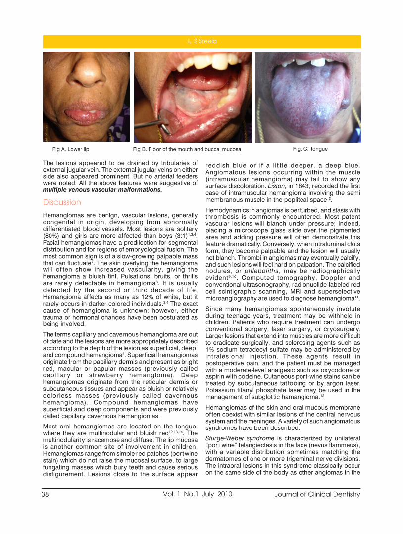
38 Journal of Clinical DentistryVol. 1 No.1 July 2010
The lesions appeared to be drained by tributaries ofex ternal jugular vein. The ex ternal jugular veins on eitherside also appeared prominent. But no arterial feederswere noted. All the above features were suggestive ofmultiple venous vascular malformations.
Discussion
Hemangiomas are benign, vascular lesions, generallycongenital in origin, developing from abnormallydif ferentiated blood vessels. Most lesions are solitary(80%) and girls are more af fected than boys (3:1)1,3,4.Facial hemangiomas have a predilection for segmentaldistribution and for regions of embryological fusion. Themost common sign is of a slow-growing palpable massthat can fluctuate7. The skin overlying the hemangiomawill of ten show increased vascularit y, giving thehemangioma a bluish tint. Pulsations, bruits, or thrillsare rarely detectable in hemangioma8. It is usuallydetected by the second or third decade of life.Hemangioma af fects as many as 12% of white, but itrarely occurs in darker colored individuals.3.4 The exactcause of hemangioma is unknown; however, eithertrauma or hormonal changes have been postulated asbeing involved.The terms capillary and cavernous hemangioma are outof date and the lesions are more appropriately describedaccording to the depth of the lesion as superficial, deep,and compound hemangioma4. Superficial hemangiomasoriginate from the papillary dermis and present as brightred, macular or papular masses (previously calledcapillar y or strawberr y hemangioma). Deephemangiomas originate from the reticular dermis orsubcutaneous tissues and appear as bluish or relativelycolorless masses (previously called cavernoushemangioma). Compound hemangiomas havesuperficial and deep components and were previouslycalled capillary cavernous hemangiomas.Most oral hemangiomas are located on the tongue,where they are multinodular and bluish red12,13,14. Themultinodularity is racemose and dif fuse. The lip mucosais another common site of involvement in children.Hemangiomas range from simple red patches (portwinestain) which do not raise the mucosal sur face, to largefungating masses which bury teeth and cause seriousdisfigurement. Lesions close to the sur face appear
reddish blue or if a lit tle deeper, a deep blue.Angiomatous lesions occurring within the muscle(intramuscular hemangioma) may fail to show anysurface discoloration. Liston, in 1843, recorded the firstcase of intramuscular hemangioma involving the semimembranous muscle in the popliteal space 2.Hemodynamics in angiomas is perturbed, and stasis withthrombosis is commonly encountered. Most patentvascular lesions will blanch under pressure; indeed,placing a microscope glass slide over the pigmentedarea and adding pressure will of ten demonstrate thisfeature dramatically. Conversely, when intraluminal clotsform, they become palpable and the lesion will usuallynot blanch. Thrombi in angiomas may eventually calcify,and such lesions will feel hard on palpation. The calcifiednodules, or phleboliths, may be radiographicallyevident9,10. Computed tomography, Doppler andconventional ultrasonography, radionuclide-labeled redcell scintigraphic scanning, MRI and superselectivemicroangiography are used to diagnose hemangioma11.Since many hemangiomas spontaneously involuteduring teenage years, treatment may be withheld inchildren. Patients who require treatment can undergoconventional surgery, laser surgery, or cryosurgery.Larger lesions that extend into muscles are more dif ficultto eradicate surgically, and sclerosing agents such as1% sodium tetradecyl sulfate may be administered byintralesional injection. These agents result inpostoperative pain, and the patient must be managedwith a moderate-level analgesic such as oxycodone oraspirin with codeine. Cutaneous port-wine stains can betreated by subcutaneous tat tooing or by argon laser.Potassium titanyl phosphate laser may be used in themanagement of subglot tic hamangioma.12Hemangiomas of the skin and oral mucous membraneof ten coexist with similar lesions of the central nervoussystem and the meninges. A variety of such angiomatoussyndromes have been described.Sturge-Weber syndrome is characterized by unilateral“por t wine” telangiectasis in the face (nevus flammeus),with a variable distribution sometimes matching thedermatomes of one or more trigeminal nerve divisions.The intraoral lesions in this syndrome classically occuron the same side of the body as other angiomas in the
Fig A. Lower lip Fig B. Floor of the mouth and buccal mucosa Fig. C. Tongue
L. S Sreela

39Journal of Clinical Dentistry Vol. 1 No.1 July 2010
patient, but the classic pat tern is not always found ineither the distribution or the expression of the variouscomponents of the syndrome. Involvement of theipsilateral meninges with associated atrophy of thecerebral cor tex can lead to epilepsy and intellectualimpairment.Maf fucci syndrome or Enchondroma with multipleangiomas was first reported by Maf fucci in 1881. It is arare genetic disorder that af fects both males andfemales. It is characterized by benign enlargements ofcartilage (enchondromas); bone deformities; and dark,irregularly shaped hemangiomas. No racial or sexualpredilection is apparent. No familial pat tern of inheritancehas been shown, but the disease manifests early in life,usually around the age of 4 or 5 years, with 25% of casesbeing congenital.In 1940, Kasabach and Merrit t described a male infantwith a discolored, indurated lesion on his lef t thigh thatrapidly grew and af fected the entire lef t leg, scrotum,abdomen, and thorax. In addition, the infant also hadconsumptive thrombocy topenia. This association hasbecome known as Kasabach-Merrit t syndrome 5. Theoriginal case is now known to have been associated withkaposiform hemangioendothelioma andthrombocytopenia. These lesions can occur anywhereon the skin which is the organ most commonly af fected.Lesions of the internal organs of ten cause bruising onthe skin. Lesions are usually painful and tender.Aggressive infiltration with ulceration and infection is rarebut can occur. Bleeding from thrombocytopenia andcoagulopathy is frequently observed.Conclusion
An awareness of the clinical appearance of angiomas isvery important. These lesions when present in the teethbearing areas may lead to fatal post ex traction bleed.Multiple angiomas are rare and when present thepossibility of associated syndromes must be ruled out.
References1. Waner M, Suen JY. Hemangiomas and vascular malformationsof the head and neck. New York: Wiley-Liss; 19992. Mulliken JB, Young AE. Vascular bir thmarks. Hemangiomasand malformations. Philadelphia: Saunders; 19883. Mulliken JB, Glowacki J. Hemangiomas and vascularmalformations in infants and children: a classiûcation basedon endothelial characteristics. Plast Reconstr Surg 1982;69:412–224. M. Ethunandan, Timothy K. Mellor; Haemangiomas andvascular malformations of the maxillofacial region—A review;British Journal of Oral and Maxillofacial Surgery 44 (2006)263–2725. Neville BW, Damm DD, Allen CM, Bouqout JE. Oral &maxillofacial pathology. 2nd ed. Philadelphia: Saunders; 2002.p. 337-69.6. Paolo Scolozzi, Francois Laurent, Tommaso Lombardi, MichelRichter; Intraoral venous malformation presenting with multiplephleboliths; Oral Surg Oral Med Oral Pathol Oral Radiol Endod2003;96:197-2007. Hasan Ayberk Altug, Vural Büyüksoy, Kemal Murat Okçu, DDS,Necdet Dogan, Diyarbakýr and Ankara; Hemangiomas of thehead and neck with phleboliths: Clinical features, diagnosticimaging, and treatment of 3 cases; Oral Surg Oral Med OralPathol Oral Radiol Endod 2007;103:e60-e648. Addante RR, Donovan MG. Right facial mass. J OralMaxillofacSurg 1994;52:1061-5.9. Allen PW, Enzinger FM. Hemangioma of the skeletal muscle:an analysis of 89 cases. Cancer 1972;29: 8-2210. Terezhalmy GT, Riley CK, Moore NS. Intramuscularhemangiomas. Quintessence Int 2000;31: 142-311. Koichi Yonetsu, Eiji Nakayama, Toshiyuki Kawazu, ShigenobuKanda, Satoru Ozeki, Masanori Shinohara; Value of contrast-enhanced magnetic resonance imaging in dif ferentiation ofhemangiomas from lymphangiomas in the oral andmaxillofacial region; Oral Surg Oral Med Oral Pathol OralRadiol Endod 1999;88:496-50012. Craig L. Hatch; Pigmented lesions of the oral cavit y; Dent Clin
N Am 49 (2005) 185–20113. Carapeto FJ, Garcia-Perez A, Winkelmann RK. Acralar teriovenous tumor. Acta Dermatovener (Stockh)1977;57:155-8.14. Connelly MG, Winkelmann RK. Acral ar teriovenous tumor. Aclinicopathological review. Am J Surg Pathol 1985;9:15-21
Panoramic view showing phleboliths (arrow mark)Fig. D. Tongue
Multiple Angiomas of oral cavity - A review and report of a case

40 Journal of Clinical DentistryVol. 1 No.1 July 2010
Photodynamic therapy (PDT) - A review
Sam Joseph V G a
Raseena Beevi .N b
Sheena P c
Introduction
Photodynamic therapy involves the use of a photoactive dye(photosensitizer) that is activated by exposure to light of a specificwavelength in the presence of oxygen. The exposure of the photosensitizerto light results in the formation of oxygen species, such as singlet oxygenand free radicals, causing localized photodamage and cell death. Theadvantage of this new approach includes rapid bacterial elimination, minimalchance of resistance development and safety of adjacent host tissue andnormal microflora. This review elucidates the evolution and use of photodynamic therapyMechanism of action
PDT involves three components: light, a photosensitizer, and oxygen. Aphotosensitizer or its metabolic precursor is administered to the patient.Upon irradiation with light of a specific wavelength, the photosensitizerundergoes a transition from a low-energy ground state to an excited singletstate. Subsequently, the photosensitizer may decay back to its ground state,with emission of fluorescence, or may undergo a transition to a higher-energy triplet state. The triplet state can react with endogenous oxygen toproduce singlet oxygen and other radical species, causing a rapid andselective destruction of the target tissue (Fig. 1).There are two mechanisms by which the triplet-state photosensitizer canreact with biomolecules.Type I involves electron/hydrogen transfer directly from the photosensitizer,producing ions, or electron/hydrogen removal from a substrate moleculeto form free radicals. These radicals react rapidly with oxygen, resulting inthe production of highly reactive oxygen species (superoxide, hydroxylradicals, hydrogen peroxide).Type II reactions produce the electronically excited and highly reactive stateof oxygen known as singlet oxygen. In PDT, it is dif ficult to distinguishbetween the two reaction mechanisms. A contribution from both Type Iand II processes indicates that the mechanism of damage is dependent onboth oxygen tension and photosensitizer concentrationLastly Type III reaction is a unique PS reaction because it is oxygenindependent. These reactions require either high concentration of the PSor a deaerated system, in order to bypass the reaction with oxygen. Underanaerobic system, radicals are generated and these can subsequently react.Figure1 shows Schematic representation of photodynamic reaction andphotodynamic therapy. Light (photon) of an appropriate energy is absorbedby a photosensitizer, which undergoes a transition from a low-energy groundstate to the excited-singlet state. The activated photosensitizer interactswith oxygen to produce singlet oxygen and other radical species that causea toxic ef fect in tumor cells or microorganisms.
Address for correspondence:a Professor, Dept of Conservative
Dentistry and Endodontics;b Asso Professor, Dept of Periodontics,c Asst Professor, Dept of ConservativeDentistry & Endodontics, Govt Dental
College [email protected]
AbstractPhotodynamic therapy (PDT) is a relatively new treatment modality. It involves the administration of aphotosensitizer followed by local illumination with visible light of specific wavelength. In the presence of oxygen,the light illumination of photosensitizer can lead to a series of photochemical reactions and consequently thegeneration of cy totoxic species. Applications of Photodynamic therapy in dentistry may include treatment ofpremalignant and malignant oral lesions, and photodynamic antimicrobial chemotherapy (PACT) of bacterialand fungal infections. This review discusses the new developments in PDT basic sciences, clinical applications,and the usefulness of various forms of PDT techniques.Key words: photodynamic therapy, photosensitiser, light delivery systems.

41Journal of Clinical Dentistry Vol. 1 No.1 July 2010
Photosensitizers
A photosensitive molecule is one which on activation byradiation or light causes another molecular componentto react (McCaughan 1999, Meisel and Kocher 2005). Ingeneral there are three basic groups of PS, Tricyclic dyes,Tetrapyrroles and Furocoumarins (Meisel and Kocher2005). More than 400 compounds are known withphotosensitizing proper ties including dyes, drugs,cosmetics chemicals, and many natural substances.Most of the sensitizers used for medical purposes belongto the following basic structuresTricyclic dyes with dif ferent meso atoms - .Acridineorange, proflavin, riboflavin, methylene blue, fluorescein,eosin, ery throsine rose Bengal and Toluidine Blue O(TBO; tolonium chloride))Tetrapyrroles - Porphyrins and derivatives, chlorophyll,phyloery thrin, phtalocyaninesFurocoumarines. Psoralen and its methoxy-derivativesxanthotoxin, bergaptenePhotosensitizer in Periodontal Therapy should be non-toxic & activated upon illumination. It Should bind withbacteria & plaque without causing any cosmetic issues,such as unwanted staining of gingiva, other sof t tissuesand easily access pathogens present in deeperperiodontal pocketsLight Sources
PDT requires a source of light that activates thephotosensitizer by exposure to low-power visible lightat a specific wavelength. Human tissue transmits red lightef ficiently, and the longer activation wavelength of thephotosensitizer results in deeper light penetration.Consequently, most photosensitizers are activated byred light between 630 and 700 nm, corresponding to alight penetration depth from 0.5 cm (at 630 nm) to 1.5cm (at 700 nm). In the past, photosensitizer activationwas achieved via a variety of light sources, such asargon-pumped dye lasers, potassium titanyl phosphate(KTP)- or neodymium:yt trium aluminum garnet (Nd/YAG)-pumped dye lasers, and gold vapor- or coppervapor-pumped dye lasers. All these laser systems arecomplex and expensive. At present, diode laser systemsthat are easy to handle, portable, and cost-ef fective areused predominantly. For treatment of larger areas, non-coherent light sources, such as tungsten filament, quartzhalogen, xenon arc, metal halide, and phosphor-coatedsodium lamps, are in use. Recently, non-laser lightsources, such as light-emit ting diodes (LEDs), aremaking an impact on PDT. The LED devices are small,lightweight, and highly flexible. In addition, LEDs arehighly ef ficient for second-generation photosensitizers,with absorption wavelengths closer to the LED peakemission.Applications of PDT in Dentistry
PHOTODYNAMIC ANTIMICROBIAL CHEMOTHERAPYOF DENTAL AND MUCOSAL INFECTIONS (PACT)In recent years, the emergence of antibiotic resistantstrains, such as methicillin resistant Staphylococcusaureus and vancomycin-resistant Enterococcus faecalis,
stimulated a search for alternative treatments. PACT hasthe potential to be an alternative treatment modality,replacing antibiotics especially for the treatment oflocalized infections of the skin and the oral cavity. Micro-organisms that are killed by PACT include bacteria, fungi,viruses, and protozoa. PACT is equally ef fective againstantibiotic-resistant and antibiotic-susceptible bacteria,and repeated photosensitization has not induced theselection of resistant strains.Effects of pact (photodynamicantimicrobial chemotherapy) on oralbiofilms
The antimicrobial activity of photosensitizers is mediatedby singlet oxygen, which, because of its high chemicalreactivity, has a direct ef fect on ex tracellular molecules.Thus, the polysaccharides present in ex tracellular matrixof polymers (EMP) of a bacterial biofilm are alsosusceptible to photodamage. Such dual activity, notexhibited by antibiotics, represents a significantadvantage of PACT. Breaking down biofilms may inhibitplasmid exchange involved in the transfer of antibioticresistance, and disrupt colonization. The activity of PACTagainst homogenous and mixed Gram-positive/Gram-negative oral biofilms has been reported for a range ofphotosensitizersPACT for Peri-Implantitis and EndodonticTreatment
Biofilms of Streptococcus intermedius prepared inartificial root canals and extracted human teeth weresubjected to PACT with TBO and a laser diode device(633 nm) equipped with an endotip that allowed light tobe transmit ted down to the apex of the tooth. S.intermedius was present in numbers similar to thosefound in heavily infected root canals. Photoactivateddisinfection signif icantly reduced the number of bacteriain both types of root canals (Williams et al., 2006). Sealet al. (2002) reported partial inactivation of S. intermediusbiofilms in root canals of ex tracted teeth, using TBO anda helium/neon laser (633 nm).In vitro and in vivo studiesusing PDT have shown that this approach has thepotential to maximize root canal disinfection. However,while disclosing and confirming the excellent antibacterialpotential of PDT, none of these studies have consistentlyexamined the ef fectiveness of this procedure insupplementing bacterial elimination af terchemomechanical procedures, which is the greatestpotential use of this technology with regard to root canaldisinfection. PDT application has an adjunctive benefitbesides mechanical treatment at sites with dif ficultaccess( furcations, deep invaginations, concavities)Necessitiy for flap operations may be reduced, patientcomfort may increase and treatment time decrease. PDTremoves the biofilm in residual deep pockets duringmaintenance phase without the need for a mechanicalintervention. PDT may decrease the risk of bacterimia,which routinely occurs af ter periodontal treatmentprocedure.Perspectives and future directions
PACT appears to be most ef ficient for treatment oflocalized and superficial infections. Thus, infections in
Photodynamic therapy (PDT) - A review

42 Journal of Clinical DentistryVol. 1 No.1 July 2010
the oral cavit y—such as mucosal and endodonticinfections, periodontal diseases, caries, and peri-implantitis—are potential targets. PACT will not replaceantimicrobial chemotherapy, but the photodynamicapproach may improve the treatment of oral infections,accelerating and lowering the cost of the treatment.Development of new photosensitizers, more ef ficientlightdelivery systems, and fur ther animal studies arerequired to establish the optimum treatment parametersbefore investigators can proceed to clinical trials andeventual clinical use. The future of PDT will depend onthe interactions bet ween clinical applications andtechnological innovations. Allison et al. (2006) havedescribed PDT as the therapy that “is truly the marriageof a drug and a light”, and, as a result, onlyinterdisciplinary research approaches can overcome allthe dif ficulties and challenges of PDT.Conclusion
PACT appears most ef ficient for localized and superficialinfections. Thus, infections in the oral cavity — such asmucosal and endodontic infections, periodontaldiseases, caries and peri-implantitis — are potentialtargets. PACT will not replace antimicrobialchemotherapy, but the photodynamic approach mayimprove treatment of oral infections, speeding uptreatment and lowering its cost.In November 17, 2005the first regulator y approval for photodynamicdisinfection therapy from Health Canada wasannounced. Also it received company-wide ISO-13485certification of quality management standard for medicaldevice companies. Based on the evidence to date,treatment of periodontal diseases using PDT of any typeis still considered experimental. Based on these articlesone must conclude that there is a great need to developan evidence-based approach to the use of lasers for thetreatment of periodontitis. It would be prudent to saythat there is insuf ficient evidence to suggest that PDT issuperior to the traditional modalities of periodontaltherapy. Everything new is not always better so an astuteclinician should critically appraise all the literature beforemaking a dramatic change from the current standard oftreatment.
References1. (Williams JA, Pearson GJ, Colles MJ (2006). Antibacterialaction of photoactivated disinfection {PAD} used onendodontic bacteria in planktonic suspension and in ar tificialand human root canals. J Dent 34:363-371.)2. (Seal GJ, Ng YL, Sprat t D, Bhat ti M, Gulabivala K (2002). Anin vitro comparison of the bactericidal ef ficacy of lethalphotosensitization or sodium hypochlorite irrigation onStreptococcus intermedius biofilms in root canals. Int EndodJ 35:268-274.)3. Fonseca MB, Junior PO, Pallota RC, et al. Photodynamictherapy for root canals infected with Enterococcus faecalis.Photomed Laser Surg 2008;26:2094. Garcez AS, Nunez SC, Lage-Marques JL, et al. Ef ficiency ofNaOCl and laser-assisted photosensitization on the reduc-tion of Enterococcus faecalis in vitro. Oral Surg,Oral MedOral Pathol Oral Radiol Endod 2006;102:e93–8.5. Garcez AS, Ribeiro MS, Tegos GP, et al. Antimicrobial pho-todynamic therapy combined with conventional endodon-tic treatment to eliminate root canal biofilm infection. La-sers Surg Med 2007;39:59–66.6. Soukos NS, Chen PS, Morris JT, et al. Photodynamic therapyfor endodontic disinfection. J Endod 2006;32:979–84.18.Williams JA, Pearson GJ, Colles MJ. Antibacterial action ofphotoactivated disinfection (PAD) used on endodontic bac-teria in planktonic suspension and in ar tificial and humanroot canals. J Dent 2006;34:363–71.7. Bergmans L, Moisiadis P, Huybrechts B, et al. Ef fect ofphoto-activated disinfection on endodontic pathogens exvivo. Int Endod J 2008;41:227–39.8. Fimple JL, Fontana CR, Foschi F, et al. Photodynamictreatment of endodontic polymicrobial infection in vitro. JEndod 2008;34:728–34.9. Meire MA, De Prijck K, Coenye T, et al. Ef fectiveness ofdif ferent laser systems to kill Enterococcus faecalis inaqueous suspension and in an infected tooth model. IntEndod J 2009;42:351–9.10. Lim Z, Cheng JL, Lim TW, et al. Light activated disinfection:an alternative endodontic) disinfection strategy. Aust DentJ 2009;54:108–14.11. Garcez AS, Nunez SC, Hamblin MR, et al. Antimicrobialef fects of photodynamic therapy on patients with necroticpulps and periapical lesion. J Endod 2008;34: 138–42.12. Bonsor SJ, Nichol R, Reid TM, et al. Microbiologicalevaluation of photo-activated disinfection in endodontics (anin vivo study). Br Dent J 2006;200:337–41. discussion
Figure 1 Application of Photosensitizer Laser exposuring (1 min per tooth )
Sam Joseph V G

43Journal of Clinical Dentistry Vol. 1 No.1 July 2010
Dental Management of a Patient withCleidocranial Dysplasia- A Case Report.
Supriya S. a
Kavita Rai b
Amitha M. Hegde c
Cleidocranial dysplasia is a generalized skeletal dysplasia leading to multipleabnormalities1-2 the major concern of the patient is most of ten the oral/dental disorders.3 Cleidocranial dysplasia (CCD) is a rare congenitaldisorder, (incidence 1:1000 000)4 primarily af fecting bones that undergointramembraneous ossification, i.e., generally the calvarian but also clavicularbones. Since its first description in 1898 by Pierre Marie and Paul Sainton,5over 1000 cases have been published in the medical literature.The skull base is dysplastic and reduced in growth. Radiographs of thenewborn demonstrate poor or absent ossification of the parietal bones.Owing to reduced growth of bones developing from the chondrocranium,increased skull width and resulting hypertelorism usually appear withassociated biparietal and frontal bone bossing. Together withunderdevelopment of the facial bones, which of ten results in a mid facedeficiency and narrow paranasal sinuses, the dysostostic growth at tributesto many patients an almost familiar resemblance. Chief intraoral expressionsinclude retained deciduous dentition, delayed eruption or retention of thepermanent dentition, multiple supernumerary teeth, actual clef t palate,hypoplastic maxilla, enlarged mandibles, a high narrow arched palate andabsence or paucity of cellular cementum on the roots.6The thoracic cage is small and bell shaped with short ribs. The pelvis showsa delayed closure of wide symphysis pubis. The dysplastic pelvis of tennecessitates caesarean section of pregnant female. Hands and feet havepseudoepiphyses at the base of the metacarpal bones and abnormalphalangeal tuf ts, and of ten cone- shaped epiphyses of the distal phalenges.Signs and symptoms were divided into the categories like supernumeraryteeth, failure of tooth eruption, hypoplastic maxilla, "clavicular sign" andother skeletal disorders. The clavicular sign was defined by the patient'sability to oppose the shoulders in front as a result of hypoplastic or aplasticclavicles. This criterion helps in easy diagnosis and the reliability of thesymptom even if not expressed in all patients.7 The wormian bones, smallepactal bones in the lambdoid suture, is also recurrently expressed inpatients with cleidocranial dysplasia.8In addition, the family history did not reveal any significant findings.Diagnosis
In 1997, the aetiological factor of cleidocranial dysplasia, RUNX2 gene,was mapped on the short arm of chromosome6 by Mundlos et al.9 RUNX2is considered a master gene in the formation of bone and dental tissue.R.Rajendran and B.Sivapathasundharam suggest several chromosome
Adress for correspondance:a Assistant Professor, Dept. of
Pedodontics and Preventive ChildrenDentistry, Govt Dental College,
Kottayam
b Professor, Dept. of Pedodontics andPreventive Children Dentistry,
A. B. Shetty Memorial Institute of DentalSciences.
c Professor and Head of the Dept.,Department of Pedodontics and
Preventive Children Dentistry,A. B. Shetty Memorial Institute of Dental
Sciences.
AbstractCleidocranial dysplasia is a generalized skeletal dysplasia leading to multiple abnormalities(1-2). The majorconcern of the patient is most of ten the oral/dental disorders.(3) Cleidocranial dysplasia (CCD) is a rare congenitaldisorder,(incidence 1:1000 000)4 primarily af fecting bones that undergo intramembraneous ossification, i.e.,generally the calvarian but also clavicular bones.CCD is also known as Marie”Sainton disease, mutationaldysostosis, and cleidocranial dysostosis. The dental abnormalities associated with it present a remarkablechallenge in orthodontic treatment planning. Early diagnosis is ex tremely important to give the patient thebest treatment options. Patients with cleidocranial dysostosis require a team approach with good communicationand cooperation from the patient. Timing of the intervention is critical, and many surgeries might be required.Here, we report a case of CCD in a 12 "year” old boy, who had come to us with a chief complaint of missingfront teeth.Key Words: Cleidocranial Dysplasia, Syndrome, Cleidocranial Dysostosis, Marie”Sainton Disease, MutationalDysostosis, and Cleidocranial Dysostosis

44 Journal of Clinical DentistryVol. 1 No.1 July 2010
abnormalities with this syndrome includingrearrangement of long arm of chromosome8 (8q22) andthe long arm of chromosome.6 10 Mutations in the core-binding factor alpha-1 (CBFA1) gene, located onchromosome 6p21, have been shown to be the causeof cleidocranial dysplasia.A strong correlation bet ween body height andsupernumerary teeth as a function of the involvementof the "runt homology domain", a structural feature ofthe RUNX2 protein involved in the DNA binding siterecognition was reported by Yoshida etal.11Case report
A male patient aged 12 years with short stature reportedto our department with a chief complaint of missingpermanent teeth. A detailed case history, was taken andupper and lower impressions for study cast, diagnosticradiographs etc. were taken.Extra oral Findings:
Frontal bossing, hyper telorism, midface deficiency andclavicular sign were present.Intra oral Findings:
High arched palate, retained primary teeth, maxillaryhypoplasia, delayed eruption of the permanent teethexcept for the first permanent molars, mobile lowerprimary incisors etc.Dentition
In upper, primary two incisors [61 and 62], canines,first primary molar [64], second primary molars [55 and65] and in the lower arch all the primary teeth werepresent. All the permanent first molars had erupted.Radiographic examination of the chest x-ray revealedabsence of clavicles and PNS view showedunderdeveloped paranal sinusus. Anorthopantomograph was taken to evaluate the statusof missing permanent teeth and was found that therewere multiple unerrupted permanent teeth and nosupernumerary teeth were present.Treatment
In the dental management of CCD patients today, totalex traction of all permanent teeth followed by fulldentures has been completely abandoned. Thetendency of ma xillary underdevelopment can beneutralised by preservation of the permanent teeththrough the natural dento-alveolar compensator ymechanism.The first molars seem to erupt spontaneously in nearlyall patients, presumably because they only have a verythin layer of bone to pass through. Or thodontictreatment seems to have been necessary in nearly allCCD cases described in the literature12 but it is generallyagreed that removal of primary teeth will improve thepossibility of spontaneous eruption. Also, bone overlyingthe normal, permanent teeth should be removed, as ithas been shown histologically,13 that the alveolar bonein CCD has abnormal dense trabeculation with multiple
reversal lines, indicating incomplete resorption.Patients with no or only a few supernumerary teeth hada much higher frequency of spontaneous eruption.14Hence we also expected an acceptable good result andplanned for the ex traction of retained primary teeth.Management of structural deformity can be correctedby orthognathic surgery /distraction osteogenesis.Treatment Done
Extraction of 71,72,81 and 82 with the surgical exposureof 31,32,41 and 42 was done under local anaesthesia.Patient was kept under observation for the eruption ofthe permanent teeth for few months and if required canbe intervened by fixed orthodontics later.A slow maxillary expansion screw with reverse pull headgear was given as an at tempt to correct the midfacehypoplasia till the growth is complete and later to go infor fur ther surgical correction.Other treatment option which shall be considered isex traction of retained primary teeth and removal of theoverlying bone over the unerupted permanent teeth,ex trusion of the teeth followed by fixed or thodontictherapy.Surgical options being distraction osteogenesis, for thecorrection of midface deficiency as quoted by Seiji et.al15 There is no doubt that the distraction osteogenesishas become one of the important treatments for facialskeletal deformity, and recent numerous reports showedwell the benefit of this treatment.16Discussion
Although there are many case reports available in theliterature, scientific interdisciplinary studies are rare.The bone defects in patients with cleidocranial dysplasiachiefly involve the clavicles and skull, although a widevariety of anomalies may be found in other bones. Theclavicles are absent, either unilaterally or bilaterally, inabout 10% of all cases. More commonly, the claviclesshow varying degrees of hypoplasia and malformation.In this case there was absence of the clavicles.Ishii et al17 assessed craniofacial morphology in youngand adult individuals with cleidocranial dysplasiaobtained from lateral head films. They demonstrated thatyoung subjects showed relatively normal jaw proportionsand morphology of the mandible, while older individualstended to express the typical signs of cleidocranialdysplasia. There was a marked discrepancy in the sizeof maxilla and mandible in this child. These dif ferencescan be at tributed to pronounced horizontal mandibulargrowth resulting from lack of vertical maxillary growthas well as impaired eruption of permanent teeth.The gnathic and dental manifestations are distinctive andmay lead to the initial diagnosis. As Neville et al18 statedthe patients of ten have a narrow, high arched palate.Prolonged retention of deciduous teeth and delay orcomplete failure of eruption of permanent teeth arecharacteristic features. In the current case report we haverecorded the presence of all the permanent first molars.
Supriya S.

45Journal of Clinical Dentistry Vol. 1 No.1 July 2010
Conclusion
Timing of inter vention seems to be of the utmostimportance for a successful result. As patients do notexperience any functional or psychosocial problems untilthe age of 9-10 years, referral for treatment will of ten betoo late to reach the 'correct-for-eruption' developmentalstage of the incisor. Another reason for late referral mightalso be the short stature of these children who, in manycases, look very young for their age.The dentist should take radiographs at least once a yearfrom the age of 5 years and ensure timely intervention.14Patients should also be observed for development ofdistal molars, cysts, etc until late adolescence.14It is essential that the pediatric dentist understands thedevelopment of dentition, generalized skeletal dysplasiaand other disorders associated with cleidocranialdysplasia.References:1. Gorlin RJ, Cohen M M Jr, Levin L S. Cleidocranial dysplasia.In : Gorlin R J, Cohen M M Jr, Levin LS(eds). Syndromes ofthe head and neck. P249-252. Ox ford: Ox ford UniversityPress, 1990.2. Jensen B L. Somatic development in cleidocranial dysplasia.Am J Med Genet 1990;35:69-743. Jensen B L, Kreiborg S. Development of the dentition incleidocranial dysplasia. J Oral Pathol Med 1990;19:89-934. Golan I, Baumer t U, Held P, Feuerbach S, Mussig D.Radiological findings and molecular genetic confirmationof cleidocranial dysplasia. Clin Radiol 2002; 57:525-529.5. Marie P, Sainton P. Sur la dysostose cleido-craniennehereditaire. Rev Neurol 1898;6:835-8386. Tyndall DA. Cleidcranial dysostosis: a nearly unrecognized
case. Gen Dent 1983; 31: 390-393.7. Mundlos S, Ot to F, Mundlos C, Mulliken JB, Aylsworth AS,Albright S, et al., Mutations involving the transcription factorCBFA 1 cause cleidocranial dysplasia. Cell 1997;89:773-779.8. I Golan, U Baumer t BP Hrala and D MuBig.Dentomaxillofacial variabilit y of cleidocranial dysplasia:clinicoradiological presentation and systematic review.Dentomaxillofacial Radiology 2003;32:347-354.9. Mundlos S, Ot to F, Mundolos C, Mulliken JB, Aylswor th AS,Albright S et al. Mutations involving the transcription factorCBFA1 cause cleidocranial dysplasia. Cell 1997; 89:773-779.10. Shafer's tex tbook of oral pathology V Edition page No.994-997.11. Yoshida T, Kanegane H, Osato M, Yanagida M, Miyawaki T,Ito Y, etal., Functional analysis of RUNX2 mutations inJapanese patients with cleidocranial dysplasia demonstratesnovel genotype- phenotype correlations. Am J Hum Genet2002, 71:724-738.12. Elomaa E, Elomaa M. Or thondontic treatment of a case ofcleidocranial dysostosis Suom Hammaslaak Toim 1967;63:142-151.13. Bishop RG. Dental management if cleidocranial dysostosis.Case repor t. Aust Dent J 1984;29:1-414. B.L. Jensen and S.Kreiborg. Dental treatment strategies incleidocranial dysplasia. Br Dent J 1992;172:243.15. Seiji Iida,Tomonao Aikawa,Natsuko Yoshimura. Maxillarydistraction osteogenesis using the intraoral distractors andthe full- covered tooth-suppor ted maxillary splint. OralMaxillofac Surg2007;65;813-81716. Swennen G, Schliephake H, Dempf R, et al: Craniofacialdistraction osteogenesis:A review of the literature: Par t 1:Clinical studies. Int J Oral Maxillofac Surg 2001;30:8917. Ishii K, Nielsen IL, Vargervik k. Characteristics of jaw growthin cleidocranial dysplasia. Clef t Palate Craniofac J 1998; 35:161-166.18. Neville,Damm,Allen,Bouquot-II Edition. Oral &MaxillofacialPathology-537-539
Dental Management of a Patient with Cleidocranial Dysplasia- A Case Report.

46 Journal of Clinical DentistryVol. 1 No.1 July 2010
Management of trismus using TrismusAppliance: A Case Report
Sandhya Gopalakrishnan a
Introduction
The term trismus denotes a motor disturbance of the trigeminal nerve,especially spasm of the masticatory muscles, with dif ficulty in opening themouth.1Causes of trismus
Several conditions may cause or predispose an individual to developtrismus. The aetiology of trismus may be broadly classified as follows.21. Pathosis in TMJ like ankylosis and derangement of TMJ2. Oodontogenic or non odontogenic infections3. Neoplasm4. Elongation of coronoid or styloid process5. Presence of foreign body6. Disturbance in trigeminal nerve7. Pathosis in muscles of mastication like trauma, prolonged or ex tremestretching8. Systemic conditions like Tetanus, Scleroderma, Rheumatoid ar thritis9. Scar tissues/adhesions in region of maxilla and mandible caused dueto trauma, burns etc10. Subsequent to radiation therapyManagement of trismus
Treatment for trismus should be directed at eliminating its cause. Diagnosticassessment should be made before any type of therapy is applied. Treatmentmodalities include.2,3,41. Heat treatment and electrotherapy2. Analgesics and muscle relaxants3. Surgical intervention4. Physiotherapy and Sof t Diet5. Trismus appliancesIndications for trismus appliances.5
1. Reparative healing before formation of dense scar2. Trismus resulting from 6-8 weeks of maxillo-mandibular fixation3. Muscle atrophy, painful motions, weakness4. Radiation therapyActions.5
1. Sof ten and stretch fibrous tissue2. Increase the range of joint motion
Adress for correspondance:a Assistant Professor, Dept of
Prosthodontics, Govt Dental College,Kottayam
Email: [email protected]
AbstractAbstract: Trismus is a problem commonly encountered by the dental practitioner. It has a number of potentialcauses, and its treatment will depend on the cause. This ar ticle reports management of trismus using treadedtapered screw.Key words: Trismus, treaded tapered screw, trismus appliances

47Journal of Clinical Dentistry Vol. 1 No.1 July 2010
3. Restore circulatory ef ficiency4. Increase muscular strength5. Retains muscular dex terityClassification of trismus appliances: 5
It can be ex ternally activated or internally activatedExternally activated
It employs forcible stretching of elevator muscles bydepressing the mandible. Force can be continuous orintermit tent; light or heavy; elastic or inelastic.Internally activated
It uses depressor muscles to open mouth.Actioncompletely depends on patient motivation andcooperationTypes of trismus appliances5
1. Dynamic Bite opener introduced by Drane in 19676,72. Threaded tapered screw 83. Screw type mouth gag by Nakajimo et al4. Tongue blades5. Finger pressure advocated by Rouse96. Continuous dynamic jaw extension apparatusCase report
55 year old female patient reported to the Departmentof Prosthodontics with reduced mouth opening followingoncosurgical procedures on the lef t alveolar ridge.
Patient had dif ficulty to incise and masticate food alongwith speech problems.On examination patient had only 14 mm of mouthopening. The normal range of mouth opening varies frompatient to patient, within a range of 40– 60 mm. The widthof the index finger at the nail bed is between 17 and 19mm. Thus, two fingers’ breadth (40 mm) up to threefingers’ breadth (54–57 mm) is the usual width ofopening. 10It was decided to fabricate treaded tapered screw. Thereason for this selection is based on ease of fabricationin the dental clinic as a chair side procedure. It is aninternally activated device which provides continuousor intermit tent force which can be controlled by thepatient.Procedure for fabrication of taperedscrew8
Step 1Cone model was prepared in Type II Gypsum product.Modelling wax was cut into 2mm width and adapted onto the cone model at 5mm interval simulating the treadsof screwStep 2Impression was made using irreversible hydrocolloidmaterial.Step 3Self cured acrylic resin was mixed and packed into theimpression and allowed to cure. The appliance thusobtained was finished and polished.The patient was advised to place the screw betweenthe posterior teeth and gradually turn it to wedge the
Step 1 Step 2 Step 3
Management of trismus using Trismus Appliance: A Case Report

48 Journal of Clinical DentistryVol. 1 No.1 July 2010
teeth apar t. The treads guided the teeth along theincreasing taper while the patient could control the timingand degree of pressure required to gradually increasethe jaw separation. Inter incisal distance was found tobe 18 mmApplication Schedule:1. Stretch to the point of discomfort, not pain2. Place appliance between teeth till snug3. Measure opening by counting rings4. Hold for 20 seconds5. Withdraw and rest for 10 seconds6. Insert to same degree of opening for 20 seconds7. Repeat for 10-15 minutes, daily 4 times.Conclusion
Trismus is a condition that impairs eating, inter feres withoral hygiene, restricts access for dental procedures, andmay adversely af fect speech and facial appearance. Thesuccess of treatment depends on recognition of thecause and initiation of appropriate management. Trismusappliances used in conjuction with physical therapy isfound to be very ef fective in the treatment of restrictedmouth opening.
References:1. Taylor EJ, ed. Dorland’s Illustrated Medical Dictionary, 27thed. Philadelphia: W.B. Saunders, 1998; p.1759.2. Marien M Jr. Trismus: causes, dif ferential diagnosis, andtreatment. Gen Dent. 1997 Jul-Aug; 45(4):350-5.3. Tveterås K, Kristensen S. The aetiology and pathogenesisof trismus. Clin Otolaryngol Allied Sci. 1986 Oct; 11(5):383-7.4. P.J. Dhanrajani,O Jonaidel; Trismus: Aetiology,dif ferentialdiagnosis and treatment. Dent Update 2002; 29: 88–945. Lund TW, Cohen JI. Trismus appliances and indications fortheir use. Quint Int 1993; 24: 275–279.6. Brown KE. Dynamic opening device for mandibular trismus.J Prostht Dent 1968; 20: 4387. Brunello DL, Mandikos MN. The use of a dynamic openingdevice in the treatment of radiation induced trismus. AustProsthodont J. 1995;9: 45-8.8. John Beumer III, Maxillofacial Rehabilitation Prosthodonticand Surgical Considerations, Ishiyaku Euro-America.Inc,1996; p. 525-5279. Rouse PB. The role of physical therapist in suppor t ofmaxillofacial patients. J Prostht Dent 1970; 24:19310. Nelson SJ, Nowlin TP, Boeselt BJ. Consideration of linearand angular values of ma ximum mandibular opening.Compend Contin Educ Dent 1992; 13: 362–363
Sandhya Gopalakrishnan