Print Preview - C:DOCUME~1chagnmaLOCALS~1Temp ... · There is no spare drive belt holder on this...
30
Transcript of Print Preview - C:DOCUME~1chagnmaLOCALS~1Temp ... · There is no spare drive belt holder on this...

Mmo2007-005 suppl MX Z X_bil.FH10 Tue Aug 22 13:26:20 2006 Page 1
Composite
CMYCMMYCYCMYK

SAFETY WARNING
Disregarding any of the safety precautions and instructionscontained in this Operator’s Guide Supplement, SAFETY VIDEOor on-product warnings may result in injury, including thepossibility of death.This Operator’s Guide Supplement and SAFETY VIDEO shouldremain with the unit at time of resale.
In USA, products are distributed by BRP US Inc.In Canada, products are distributed by Bombardier Recreational Prod-ucts Inc.
The following are trademarks of Bombardier Recreational ProductsInc. or its subsidiaries.
SKI-DOO® MX Z® REVTM
DESSTM Pilot™ TRA™SC-4™
Printed in Canada. (mmo2007-005 DR)®™ and the BRP logo are trademarks of Bombardier Recreational Products Inc. or its affiliates.©2006 Bombardier Recreational Products Inc. and BRP US Inc. All rights reserved.

Dear 2007 MX Z XTM 440 owner, informations in the 2007 REVTM
SERIES OPERATOR'S GUIDE (P/N 520 000 610) also apply to
your MX Z X 440 except for the subjects covered in this Sup-
plement.
__________________________ 1

TABLE OF CONTENTS
VEHICLE INFORMATION
RACING APPLICATION . . . . . . . . . . . . . . . . . . . . . . . . . . . . . . . . . . . . . . . . . . . 4
CONTROLS/INSTRUMENTS/EQUIPMENT . . . . . . . . . . . . . . . . . . . . 5
1) Speedometer/Tachometer . . . . . . . . . . . . . . . . . . . . . . . . . . . . . . . . . . 512) Tether Cut-Out Switch . . . . . . . . . . . . . . . . . . . . . . . . . . . . . . . . . . . . . 513) Engine Cut-Out Switch . . . . . . . . . . . . . . . . . . . . . . . . . . . . . . . . . . . . 614) High Beam/Low Beam Switch . . . . . . . . . . . . . . . . . . . . . . . . . . . . 618) Fuel Level . . . . . . . . . . . . . . . . . . . . . . . . . . . . . . . . . . . . . . . . . . . . . . . . . . 730) Fuses (not shown) . . . . . . . . . . . . . . . . . . . . . . . . . . . . . . . . . . . . . . . . . 739) Spare Drive Belt Holder (not shown) . . . . . . . . . . . . . . . . . . . . . . 743) Pre-Heat Switch. . . . . . . . . . . . . . . . . . . . . . . . . . . . . . . . . . . . . . . . . . . . 744) Primer Button . . . . . . . . . . . . . . . . . . . . . . . . . . . . . . . . . . . . . . . . . . . . . . 8
RECOMMENDED FUEL AND OIL. . . . . . . . . . . . . . . . . . . . . . . . . . . . . . . . 9
OPERATING INSTRUCTIONS. . . . . . . . . . . . . . . . . . . . . . . . . . . . . . . . . . . . 13
Engine Starting Procedure . . . . . . . . . . . . . . . . . . . . . . . . . . . . . . . . . . . . . 13Suspensions Adjustments . . . . . . . . . . . . . . . . . . . . . . . . . . . . . . . . . . . . . 13
SPECIFICATIONS . . . . . . . . . . . . . . . . . . . . . . . . . . . . . . . . . . . . . . . . . . . . . . . . . 15
MAINTENANCE INFORMATION
ENGINE SYSTEM . . . . . . . . . . . . . . . . . . . . . . . . . . . . . . . . . . . . . . . . . . . . . . . . . 20
Water Pump Shaft Oil Reservoir. . . . . . . . . . . . . . . . . . . . . . . . . . . . . . . 20
DRIVE SYSTEM . . . . . . . . . . . . . . . . . . . . . . . . . . . . . . . . . . . . . . . . . . . . . . . . . . . 21
Drive Belt Removal/Installation . . . . . . . . . . . . . . . . . . . . . . . . . . . . . . . . 21Drive Belt Height Adjustment . . . . . . . . . . . . . . . . . . . . . . . . . . . . . . . . . 22
ELECTRICAL SYSTEM. . . . . . . . . . . . . . . . . . . . . . . . . . . . . . . . . . . . . . . . . . . . 25
Taillight Bulb Replacement. . . . . . . . . . . . . . . . . . . . . . . . . . . . . . . . . . . . . 25
WARRANTY
LIMITED WARRANTY VALIDATION . . . . . . . . . . . . . . . . . . . . . . . . . . . . . 28
2 __________________________

VEHICLEINFORMATION
__________________________ 3

RACING APPLICATION
For racing application, the main jets have to be replaced according tothe chart found on belt guard.
���������������������� �������������� � ������ �������� ������������ ������������������������ ������� ����� ���������������������� ���� �� ��� ������������������� �!������ � �������� ����������� ����� ��������� ����"#�$%&��'��&�()*����+�� ���� �,������������ ������� ��������� ������������������������������ �� ������� ��
������� �� ���-�-��� � ����� ��� �-��� �������������� ��.������/�������������� �� ���-� �������� �������������� ���� ���-� ������0��-��,������ � ��� �� � /�������������-�-1-!������� �����������2��������� ��2��������2�� ����� ���������"#�$%&��'��&�()*����3� � �� ���� ��������� ��,�1���1� ����������������� ����������������� ����� ��� � ����������� -��1���������� ���
����������
+ ����� ���4��������2�� ����"#'�� + ����� ���4��������2�� ����"#'��
5%&6645&7��%8 6�&45%&66
4*9
4:9
�9
�:9
4;
:;
<*
=9
� �4��� � �4���
��������4�+7�.�5>�%�� ?�5.�7%�3%��5�3�.4�5�%@7%������������
<<94<<9<*94<*9<:94<:9<994<99
<*94<*9<:94<:9<994<99*"94*"9
mmo2007-005-001
4 __________________________

CONTROLS/INSTRUMENTS/EQUIPMENT
��
�������
�
�
��
�
��
��
� ��
�
��
�
��
�
��
�
NOTE: See description of numbered items in 2007 REV SERIES OP-ERATOR’S GUIDE (P/N 520 000 610) except for the following.
1) Speedometer/Tachometer
The MX Z X 440 uses the same combined speedometer/tachometerfunctions as a Summit liquid cooled model.
12) Tether Cut-Out Switch
There is no DESS™ (Digitally Encoded Security System) on this ve-hicle.
__________________________ 5

13) Engine Cut-Out Switch
Located on right side of handlebar this switch is used to stop theengine.
���
������
�
���
14) High Beam/Low Beam Switch
Allows selection of headlamp high beam or low beam.
�
�
mmo2006-007-002_a
1. Low beam2. High beam
6 __________________________
18) Fuel Level
Open fabric door to see the fuel level through the translucent fueltank.
������� �
1. Fabric door
30) Fuses (not shown)
There is no fuse on this vehicle.
39) Spare Drive Belt Holder (not shown)
There is no spare drive belt holder on this vehicle.
43) Pre-Heat Switch
Racing Application Only
NOTE: This switch is disabled (not operative) on vehicles modifiedfor warranty validation. To run engine with 91 octane number fuel(R + M)/2 inside North America (95 RON outside North America),this switch must be disabled.
__________________________ 7

�
����� �
�
1. Button depressed: Pre-heat timing curve2. Button released: 108 (R + M)/2+ octane timing curve for North America
version (98 RON + Octane timing curve for outside North America)
After starting the engine, push and hold the pre-heat switch buttonin order to pre-heat the tuned pipe. Release pre-heat switch buttononce the tuned is pre-heated.
44) Primer Button
Pull and push button. It is not necessary when engine is warm.
To prime, activate button until a pumping resistance is felt. Fromthis point, pump 2 or 3 times to inject fuel in intake manifold. Afterpriming, ensure that primer button is pushed back.
NOTE: In very cold temperature, it is recommended to rotate primerbutton 3 - 4 turns prior to pull it. This will eliminate the possibility ofsticking.
8 __________________________
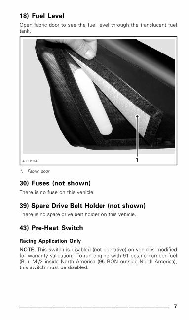
RECOMMENDED FUEL AND OIL
Fuel
Vehicles with Valid Warranty (pre-heat switch disabled)
Use premium unleaded gasoline, available from most servicestations or oxygenated fuel containing a maximum total of 10%of ethanol or methanol or both. The gasoline used must have thefollowing recommended minimum octane number.
LOCATION OCTANE NUMBER
Inside North America (91 (RON + MON)/2)
Outside North America 95 RON
Vehicles without Warranty (pre-heat switch enabled)
Use racing fuel with the following octane number.
MINIMUM
LOCATION OCTANE NUMBER
Inside North America (108 (RON + MON)/2)
Outside North America 113 RON
RECOMMENDED
LOCATION OCTANE NUMBER
Inside North America (114 (RON + MON)/2)
Outside North America 119 RON
NOTE: The fuel tank cap specifies an octane number of 91 as a min-imum. A higher octane number is required in racing application.
All Vehicles
CAUTION: Never experiment with other fuels. The use of unrec-ommended fuel can result in snowmobile performance deterio-ration and damage to critical parts in the fuel system and enginecomponents.
__________________________ 9
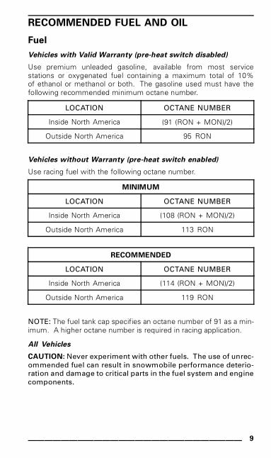
� WARNINGAlways stop engine before refueling. Open cap slowly. If a dif-ferential pressure condition is noticed (whistling sound heardwhen loosening fuel tank cap) have vehicle inspected and/orrepaired before further operation. Fuel is flammable and ex-plosive under certain conditions. Never use an open flame tocheck fuel level. Never smoke or allow flame or spark in vicin-ity. Always work in a well-ventilated area. Never top up thefuel tank before placing the vehicle in a warm area. As tem-perature increases, fuel expands and may overflow. Alwayswipe off any fuel spillage from the vehicle.
Fuel System Antifreeze
When using oxygenated fuel, additional gas line antifreeze or waterabsorbing additives are not required and should be not used.
When using non-oxygenated fuel, we highly recommend the use ofisopropyl base gas line antifreeze in a proportion of 150 mL (5 U.S. oz)of gas line antifreeze added to 40 liters (10-1/2 U.S. gal) of gas.
This precaution is in order to reduce the risk of frozen carburetorswhich may lead, in certain cases, to high fuel consumption or severedamage to engine.
IMPORTANT: Use only methyl hydrate free gas line antifreeze.
Oil
NOTE: Premix fuel/oil ratio is 33:1
CAUTION: Never experiment with other fuel/oil ratios. Use onlyoil that can flow at - 40°C (- 40°F).
Oil must be mixed with fuel at the ratio of 33:1 in a jerrycan then,be poured in the fuel tank. Refer to chart below as a guideline toproperly premix oil with fuel.
Use only two-stroke engine injection oil, sold by authorized SKI-DOOdealers.
10 _________________________
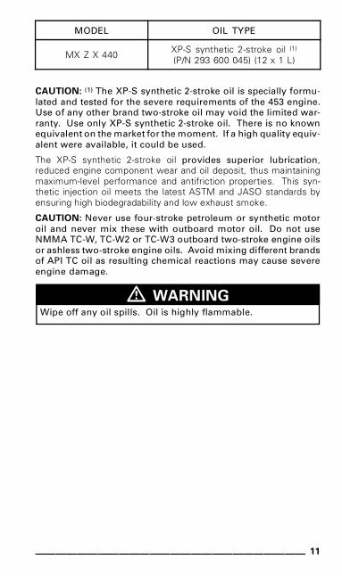
MODEL OIL TYPE
MX Z X 440 XP-S synthetic 2-stroke oil (1)
(P/N 293 600 045) (12 x 1 L)
CAUTION: (1) The XP-S synthetic 2-stroke oil is specially formu-lated and tested for the severe requirements of the 453 engine.Use of any other brand two-stroke oil may void the limited war-ranty. Use only XP-S synthetic 2-stroke oil. There is no knownequivalent on the market for the moment. If a high quality equiv-alent were available, it could be used.
The XP-S synthetic 2-stroke oil provides superior lubrication,reduced engine component wear and oil deposit, thus maintainingmaximum-level performance and antifriction properties. This syn-thetic injection oil meets the latest ASTM and JASO standards byensuring high biodegradability and low exhaust smoke.
CAUTION: Never use four-stroke petroleum or synthetic motoroil and never mix these with outboard motor oil. Do not useNMMA TC-W, TC-W2 or TC-W3 outboard two-stroke engine oilsor ashless two-stroke engine oils. Avoid mixing different brandsof API TC oil as resulting chemical reactions may cause severeengine damage.
� WARNINGWipe off any oil spills. Oil is highly flammable.
__________________________ 11
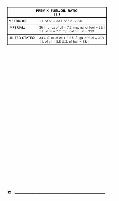
PREMIX FUEL/OIL RATIO
33:1
METRIC (SI): 1 L of oil + 33 L of fuel = 33/1
IMPERIAL: 35 imp. oz of oil + 7.2 imp. gal of fuel = 33/11 L of oil + 7.2 imp. gal of fuel = 33/1
UNITED STATES: 34 U.S. oz of oil + 8.8 U.S. gal of fuel = 33/11 L of oil + 8.8 U.S. of fuel = 33/1
12 _________________________
OPERATING INSTRUCTIONS
Engine Starting Procedure• Re-check throttle control lever operation.• Ensure that the emergency cut-out switch is in the ON position.• Ensure the tether cut-out cap is in position and that the cord is
attached to your clothing.• To prime, activate button until a pumping resistance is felt. From
this point, pump 2 or 3 times to inject fuel in intake manifold.After priming, ensure that primer button is pushed back.
NOTE: In very cold temperature, it is recommended to rotate primerbutton 3 - 4 turns prior to pull it. This will eliminate the possibility ofsticking.
NOTE: Priming is not necessary when engine is warm.• Grab manual starter handle, pull handle slowly until a resistance
is felt, then hold handle firmly and pull vigorously to start engine.
Suspensions Adjustments
In addition to all suspension adjustments described in REV SERIESOPERATOR’S GUIDE, take note of the 2 following points.
Shocks
All 4 shocks feature 2 adjustments.
Low Speed Compression Adjuster
The low speed adjuster modifies the damping force for small suspen-sion velocities — less than 0.75 m/s (2.5 ft/s). It tunes the vehiclefor braking, cornering, hole shot and all the bumps that create lowspeed movement in the suspension. This adjuster has 4 turns ofadjustment. Use a flat screwdriver to adjust it. Turning it clockwiseincreases shock damping action (stiffer) for these low compressionspeeds.
__________________________ 13
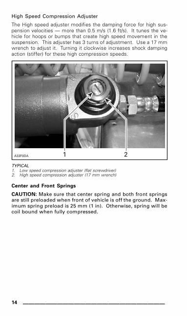
High Speed Compression Adjuster
The High speed adjuster modifies the damping force for high sus-pension velocities — more than 0.5 m/s (1.6 ft/s). It tunes the ve-hicle for hoops or bumps that create high speed movement in thesuspension. This adjuster has 3 turns of adjustment. Use a 17 mmwrench to adjust it. Turning it clockwise increases shock dampingaction (stiffer) for these high compression speeds.
������� � �
TYPICAL1. Low speed compression adjuster (flat screwdriver)2. High speed compression adjuster (17 mm wrench)
Center and Front Springs
CAUTION: Make sure that center spring and both front springsare still preloaded when front of vehicle is off the ground. Max-imum spring preload is 25 mm (1 in). Otherwise, spring will becoil bound when fully compressed.
14 _________________________

SPECIFICATIONS
NOTE: Because of its ongoing commitment to product quality andinnovation, BRP reserves the right, at any time, to make changes indesign and specifications and/or to make additions to, or improve-ments in its products without imposing any obligation upon itself toinstall them on its products previously manufactured.
MODEL MX Z X 440
ENGINE SYSTEM
Engine type 453
Cylinders 2
Displacement cc (in3) 436.7 (26.6)
Bore mm (in) 65.0 (2.56)
Stroke mm (in) 65.8 (2.59)
Maximum power enginespeed ± 100 RPM 8400
Carburetion 2 x TMX-34
Exhaust system Single tuned pipe,baffle muffler
DRIVE SYSTEM
Drive pulley type TRA™ III light
Driven pulley type Team rapid reaction
Engagement 5700 RPM
Small sprocket number of teeth 21
Large sprocket number of teeth 45
Drive sprocket number of teeth 8
Brake system Hydraulic caliper,self adjusting
Track nominal width 381 mm (15 in)
Track nominal length 3074 mm (121 in)
Track profile height 44.5 mm (1.75 in)
__________________________ 15
MODEL MX Z X 440
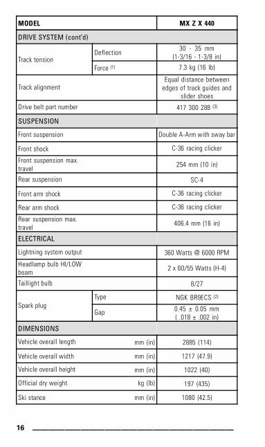
DRIVE SYSTEM (cont’d)
Deflection30 - 35 mm
(1-3/16 - 1-3/8 in)Track tensionForce (1) 7.3 kg (16 lb)
Track alignmentEqual distance between
edges of track guides andslider shoes
Drive belt part number 417 300 288 (3)
SUSPENSION
Front suspension Double A-Arm with sway bar
Front shock C-36 racing clicker
Front suspension max.travel 254 mm (10 in)
Rear suspension SC-4
Front arm shock C-36 racing clicker
Rear arm shock C-36 racing clicker
Rear suspension max.travel 406.4 mm (16 in)
ELECTRICAL
Lightning system output 360 Watts @ 6000 RPM
Headlamp bulb HI/LOWbeam 2 x 60/55 Watts (H-4)
Taillight bulb 8/27
Type NGK BR9ECS (2)
Spark plugGap 0.45 ± 0.05 mm
( .018 ± .002 in)
DIMENSIONS
Vehicle overall length mm (in) 2885 (114)
Vehicle overall width mm (in) 1217 (47.9)
Vehicle overall height mm (in) 1022 (40)
Official dry weight kg (lb) 197 (435)
Ski stance mm (in) 1080 (42.5)
16 _________________________

MODEL MX Z X 440
LIQUIDS
TypeFuel
Minimum octaneSee RECOMMENDED FUEL
Type XP-S synthetic 2-stroke oil(P/N 293 600 045) (12 x 1 L)Mixing oil
Premix ratio 33:1
Brake system fluid SRF (DOT 4) orGTLMA (DOT 4)
Chaincase oil typeXP-S synthetic chaincase oil
(P/N 413 803 300)(12 x 355 mL)
Mixture
Ethyl glycol/water mix (50%coolant, 50% distilled water)
Use coolant specificallydesigned for aluminum
enginesCoolant
Premix (P/N 413 711 802)(16 x 1 L)
Water pump shaft oilXP-S mineral injectionoil (P/N 413 802 900)
(12 x 1 L)
CAPACITIES
Fuel tank L (U.S. gal) 21 (5.5)
Chaincase mL (U.S. oz) 250 (8.5)
Cooling system L (U.S. oz) 3.5 (118)(1) Measure gap between slider shoe and bottom inside of track when exerting a
downward pull to the track.(2) CAUTION: Do not attempt to adjust gap on spark plug BR9ECS.(3) Drive belt height must be adjusted every time a new drive belt is installed.
Confirm drive belt part number application with an authorized SKI-DOO dealer.
__________________________ 17

18 _________________________

MAINTENANCEINFORMATION
__________________________ 19

ENGINE SYSTEM
Water Pump Shaft Oil Reservoir
CAUTION: Vehicle must be on a level surface before checkingany fluid levels.
Use XP-S mineral injection oil (P/N 413 802 900) (12 x 1 L).
Fill up to mark.
�������
��
1. Water pump shaft oil filling mark2. Coolant cold level mark
20 _________________________
DRIVE SYSTEM
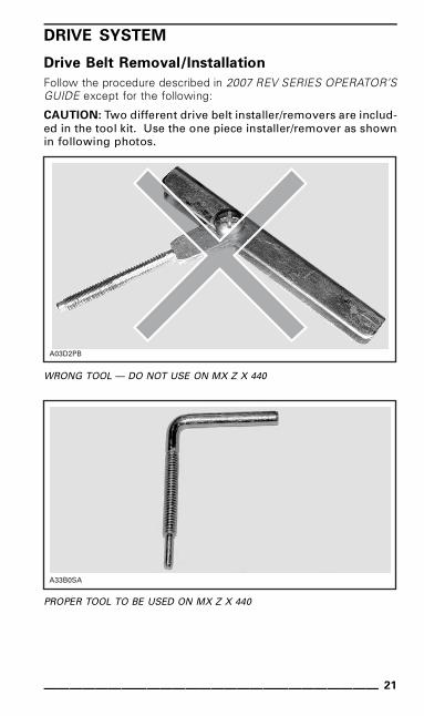
Drive Belt Removal/Installation
Follow the procedure described in 2007 REV SERIES OPERATOR’SGUIDE except for the following:
CAUTION: Two different drive belt installer/removers are includ-ed in the tool kit. Use the one piece installer/remover as shownin following photos.
������
WRONG TOOL — DO NOT USE ON MX Z X 440
���� �
PROPER TOOL TO BE USED ON MX Z X 440
__________________________ 21

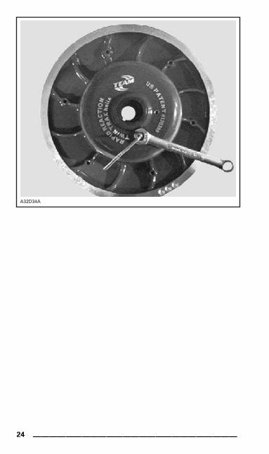
�������
PROPER TOOL OPENING DRIVEN PULLEY OF MX Z X 440
Drive Belt Height Adjustment
To obtain maximum vehicle performance and drive belt longevity,drive belt height adjustment must be performed every time a newdrive belt is installed.
NOTE: If correct adjustment is unattainable, contact an authorizedSKI-DOO dealer.
The drive belt cord should be flush with driven pulley edge. Adjustas required.
22 _________________________

��������
TYPICAL1. Flush
To adjust the sheaves, loosen the 7/16 in jam nut on the belt widthadjuster.
Using a 1/8 in Allen wrench (P/N 920001), adjust the threaded setscrew as needed.
NOTE: Turn the set screw in (clockwise) to increase the distancebetween the sheaves and out (counter-clockwise) to decrease thedistance.
Tighten the jam nut after the belt adjustment has been made.
__________________________ 23
�������
24 _________________________

ELECTRICAL SYSTEM
Taillight Bulb Replacement
Pull on taillight housing to release it from seat plastic cover.
Turn bulb support counterclockwise and pull to expose the bulb.
Pull on bulb to remove.
__________________________ 25

26 _________________________

WARRANTY
__________________________ 27
LIMITED WARRANTY VALIDATION
Because of its racing application, the 2007 MX Z X 440 is shippedfrom the factory with high compression ratio (CR) combustion cham-ber inserts installed.
To validate limited warranty coverage and to run engine with 91 oc-tane number gasoline (R + M)/2 inside North America (95 RON out-side North America), the following modifications must be done at
predelivery before using the vehicle.1. Low CR combustion chamber inserts must be installed on en-
gine. The high CR combustion chamber inserts must be re-turned to BRP Warranty Department.
2. Replace the main jets with the ones recommended in the PRE-DELIVERY BULLETIN.
3. Replace the needle jets with the ones recommended in thePREDELIVERY BULLETIN.
4. Disconnect the pre-heat switch as explained in the PREDELIV-ERY BULLETIN.
5. Install Power Jet (jet 0) as explained in the PREDELIVERY BUL-LETIN.
6. Disconnect, remove and return to BRP Warranty Departmentthe EGT pipe sensor.
7. Plug-in EGT pipe sensor hole as explained in the PREDELIVERYBULLETIN.
28 _________________________