PRINCIPLES OF TRANSMISSION LINES (1).docx
42
PRINCIPLES OF TRANSMISSION LINES LEARNING OBJECTIVES Upon completion of this chapter, you will be able to: 1. State what a transmission line is and how transmission lines are used. 2. Explain the operating principles of transmission lines. 3. Describe the five types of transmission lines. 4. State the length of a transmission line. 5. Explain the theory of the transmission line. 6. Define the term LUMPED CONSTANTS in relation to a transmission line. 7. Define the term DISTRIBUTED CONSTANTS in relation to a transmission line. 8. Define LEAKAGE CURRENT. 9. Describe how the electromagnetic lines of force around a transmission line are affected by the distributed constants. 10. Define the term CHARACTERISTIC IMPEDANCE and explain how it affects the transfer of energy along a transmission line.
Transcript of PRINCIPLES OF TRANSMISSION LINES (1).docx

PRINCIPLES OF TRANSMISSION LINES
LEARNING OBJECTIVES
Upon completion of this chapter, you will be able to:
1. State what a transmission line is and how transmission lines are used.
2. Explain the operating principles of transmission lines.
3. Describe the five types of transmission lines.
4. State the length of a transmission line.
5. Explain the theory of the transmission line.
6. Define the term LUMPED CONSTANTS in relation to a transmission line.
7. Define the term DISTRIBUTED CONSTANTS in relation to a transmission line.
8. Define LEAKAGE CURRENT.
9. Describe how the electromagnetic lines of force around a transmission line are affected by the distributed constants.
10. Define the term CHARACTERISTIC IMPEDANCE and explain how it affects the transfer of energy along a transmission line.

INTRODUCTION TO TRANSMISSION LINES
A TRANSMISSION LINE is a device designed to guide electrical energy from one point to another. It is used, for example, to transfer the output RF energy of a transmitter to an antenna. This energy will not travel through normal electrical wire without great losses. Although the antenna cannot be connected directly to the transmitter, the antenna is usually located some distance away from the transmitter. On board ship, the transmitter is located inside a radio room and its associated antenna is mounted on a mast. A transmission line is used to connect the transmitter and the antenna.
The transmission line has a single purpose for both the transmitter and the antenna. This purpose is to transfer the energy output of the transmitter to the antenna with the least possible power loss.
From the receiver side, the antenna is responsible for picking up any radio signals in the air, and passing them to the receiver with the minimum amount of distortion so that the radio has its best chance to decode the signal. For these reasons, the RF cable has a very important role in radio systems: it must maintain the integrity of the signals in both direction.
How well this is done depends on the special physical and electrical characteristics (impedance and resistance) of the transmission line.
TERMINOLOGY
All transmission lines have two ends (see figure -1). The end of a two-wire transmission line connected to a source is ordinarily called the INPUT END or the GENERATOR END. Other names given to this end are TRANSMITTER END, SENDING END, and SOURCE.
The other end of the line is called the OUTPUT END or RECEIVING END. Other names given to the output end are LOAD END and SINK.
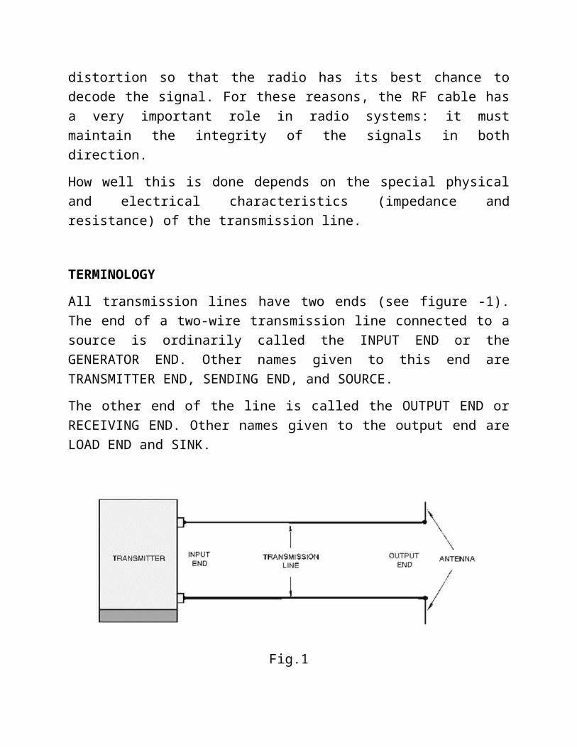
Fig.1
You can describe a transmission line in terms of its impedance. The ratio of voltage to current (Ein/Iin) at the input end is known as the INPUT IMPEDANCE (Zin). This is the impedance presented to the transmitter by the transmission line and its load, the antenna. The ratio of voltage to current at the output (Eout/Iout) end is known as the OUTPUT IMPEDANCE (Zout). This is the impedance presented to the load by the transmission line and its source. If an infinitely long transmission line could be used, the ratio of voltage to current at any point on that transmission line would be some particular value of impedance. This impedance is known as the CHARACTERISTIC IMPEDANCE.
TYPES OF TRANSMISSION MEDIUMS
The Navy uses many different types of TRANSMISSION MEDIUMS in its electronic applications. Each medium (line or wave guide) has a certain characteristic impedance value, current-carrying capacity, and physical shape and is designed to meet a particular requirement.
The five types of transmission mediums that we will discuss in this chapter include:
1. PARALLEL-LINE, 2. TWISTED PAIR, 3. SHIELDED PAIR, 4. COAXIAL LINE, and5. WAVEGUIDES.

The use of a particular line depends, among other things, on the applied frequency, the power-handling capabilities, and the type of installation.
NOTE: In the following paragraphs, we will mention LOSSES several times. We will discuss these losses more thoroughly under "LOSSES IN TRANSMISSION LINES."
Two-Wire Open Line
One type of parallel line is the TWO-WIRE OPEN LINE illustrated in figure -2. This line consists of two wires that are generally spaced from 2 to 6 inches apart by insulating spacers. This type of line is most often used for power lines, rural telephone lines, and telegraph lines. It is sometimes used as a transmission line between a transmitter and an antenna or between an antenna and a receiver. An advantage of this type of line is its simple construction. The principal disadvantages of this type of line are the high radiation losses and electrical noise pickup because of the lack of shielding. Radiation losses are produced by the changing fields created by the changing current in each conductor.
Fig.2
Another type of parallel line is the TWO-WIRE RIBBON (TWIN LEAD) illustrated in figure -3. This type of transmission line is commonly used to connect a television receiving antenna to a home television set. This line is essentially the same as the two-wire open line except that uniform spacing is assured by embedding the two wires in a low-loss dielectric, usually polyethylene. Since the wires are embedded in the thin ribbon of polyethylene, the dielectric space is partly air and partly polyethylene.

Twisted Pair
The TWISTED PAIR transmission line is illustrated in figure -4. As the name implies, the line consists of two insulated wires twisted together to form a flexible line without the use of spacers. It is not used for transmitting high frequency because of the high dielectric losses that occur in the rubber insulation. When the line is wet, the losses increase greatly.
Shielded Pair
The SHIELDED PAIR, shown in figure -5, consists of parallel conductors separated from each other and surrounded by a solid dielectric. The conductors are contained within a braided copper tubing that acts as an electrical shield. The assembly is covered with a rubber or flexible composition coating that protects the line from moisture and mechanical damage. Outwardly, it looks much like the power cord of a washing machine or refrigerator.
Coaxial Lines
RF cables are, for frequencies higher than HF, almost exclusively coaxial cables (or "coax" for short, derived from the words "of common axis"). Coax cables have a core wire, surrounded by a non-conductive material (which is called dielectric or insulation), and then surrounded by an encompassing shielding which is often made of braided wires. The dielectric keeps the core and the shielding apart. Finally, the coax is protected by an outer shielding which will generally be a PVC material. The inner conductor carries the RF signal and the outer shield is there to keep the RF signal from radiating to the atmosphere and to stop outside signals from interfering with the signal carried by the core. Another interesting fact is that the electrical signal always travels along the outer layer of the central conductor:

the larger the central conductor, the better signal will flow. This is called the “skin effect”.
Even though the coaxial construction is good at containing the signal on the core wire, there is some resistance to the electrical flow: as the signal travels down the core, it will fade away. This fading is known as attenuation, and is measured in dB/m. The rate of attenuation is a function of the signal frequency and the physical construction of the cable itself. There are two types of COAXIAL LINES:
RIGID (AIR) COAXIAL LINE and FLEXIBLE (SOLID) COAXIAL LINE.
The physical construction of both types is basically the same; that is, each contains two concentric conductors.
The rigid coaxial line consists of a central, insulated wire (inner conductor) mounted inside a tubular outer conductor. This line is shown in figure -6. In some applications, the inner conductor is also tubular. The inner conductor is insulated from the outer conductor by insulating spacers or beads at regular intervals. The spacers are made of Pyrex, polystyrene, or some other material that has good insulating characteristics and low dielectric losses at high frequencies.
The chief advantage of the rigid line is its ability to minimize radiation losses. The electric and magnetic fields in a two-wire parallel line extend into space for relatively great distances and radiation losses occur. However, in a coaxial line no electric or magnetic fields extend outside of the outer conductor. The fields are confined to the space between the two conductors, resulting in a perfectly shielded coaxial line. Another advantage is that interference from other lines is reduced.
The rigid line has the following disadvantages: (1) it is expensive to construct; (2) it must be kept dry to prevent excessive leakage between the two conductors; and

(3) although high-frequency losses are somewhat less than in previously mentioned lines, they are still excessive enough to limit the practical length of the line.
Leakage caused by the condensation of moisture is prevented in some rigid line applications by the use of an inert gas, such as nitrogen, helium, or argon. It is pumped into the dielectric space of the line at a pressure that can vary from 3 to 35 pounds per square inch. The inert gas is used to dry the line when it is first installed and pressure is maintained to ensure that no moisture enters the line.
Flexible coaxial lines (figure -7) are made with an inner conductor that consists of flexible wire insulated from the outer conductor by a solid, continuous insulating material. The outer conductor is made of metal braid, which gives the line flexibility. Early attempts at gaining flexibility involved using rubber insulators between the two conductors. However, the rubber insulators caused excessive losses at high frequencies.
Because of the high-frequency losses associated with rubber insulators, polyethylene plastic was developed to replace rubber and eliminate these losses. Polyethylene plastic is a solid substance that remains flexible over a wide range of temperatures. It is unaffected by seawater, gasoline, oil, and most other liquids that may be found aboard ship. The use of polyethylene as an insulator results in greater high-frequency losses than the use of air as an insulator. However, these losses are still lower than the losses associated with most other solid dielectric materials.
Practical Hints: How to choose the proper cable –

“The shorter the better !” the first rule when you have to place a cable is to try to keep it as short as possible. The power loss is not linear, so doubling the cable length means that you are going to lose much more than twice the power. In the same way, halfening the cable length gives you more than twice the power at the antenna. The best solution is to place the transmitter as close as possible to the antenna, even when this means placing it on the top of a mast.
“The cheaper the worse!” the second golden rule is that the money you invest in buying a good quality cable is a bargain. Cheap cables are intended to be used at low frequencies, not higher than VHF. Microwaves require the highest quality cables, all other options are nothing else than a dummy load.
Always use “Heliax” (also called “Foam”) cables for connecting the transmitter to the antenna, and Semi-rigid cables to interconnect the other devices in the RF chain (i.e. instrumentation). Semi-rigid cables consist of a solid inner conductor (usually copper or silver/copper-plated steel), a solid PTFE dielectric and a solid copper outer pipe. They are sealed, and their rigid construction means that they cannot flex. However the loss is still relatively high due to the small diameter, and they are therefore rarely used as a feeder to an antenna. Heliax cables are basically larger diameter flexible versions of Semi-rigid cables, with a corrugated solid outer conductor to enable them to flex more easily. They can be built in two ways: using air or foam as dielectric. The first solution is the most expensive, guarantees the minimum loss but is very difficult to handle. The second solution is more lossy but less expensive and easier to install. A special procedure is required when soldering connectors, in order to maintain the foam dielectric dry and uncorrupted.
Never step over a cable, never bend it too much, and never try to unplug a connector pulling directly the cable. All those behaviors may change the mechanical characteristic of the cable and therefore its impedance, shortcut the inner conductor with the shield, or even break the line. Those problems are difficult to track and recognize and can lead to unpredictable behavior of the radio link.
Waveguides
Above 2 GHz, the wavelength is short enough to allow practical, efficient energy transfer by different means. A waveguide is a conducting tube through which

energy is transmitted in the form of electromagnetic waves. The tube acts as a boundary that confines the waves in the enclosed space. The skin effect prevents any electromagnetic effects from being evident outside the guide. The electromagnetic fields are propagated through the waveguide by means of reflections against its inner walls, which are considered perfect conductors. The intensity of the fields is greatest at the center along the X dimension, and must diminish to zero at the end walls because the existence of any field parallel to the walls at the surface would cause an infinite current to flow in a perfect conductor. Waveguides, of course, cannot carry RF in this fashion.
The WAVEGUIDE is classified as a transmission line. However, the method by which it transmits energy down its length differs from the conventional methods. Waveguides are cylindrical, elliptical, or rectangular (cylindrical and rectangular shapes are shown in figure -8). The rectangular waveguide is used more frequently than the cylindrical waveguide.
The term waveguide can be applied to all types of transmission lines in the sense that they are all used to guide energy from one point to another. However, usage has generally limited the term to mean a hollow metal tube or a dielectric transmission line. In this chapter, we use the term waveguide only to mean "hollow metal tube." It is interesting to note that the transmission of electromagnetic energy along a waveguide travels at a velocity somewhat slower than electromagnetic energy traveling through free space.
A waveguide may be classified according to its cross section (rectangular, elliptical, or circular), or according to the material used in its construction (metallic or dielectric). Dielectric waveguides are seldom used because the dielectric losses for all known dielectric materials are too great to transfer the electric and magnetic fields efficiently.

The installation of a complete waveguide transmission system is somewhat more difficult than the installation of other types of transmission lines. The radius of bends in the waveguide must measure greater than two wavelengths at the operating frequency of the equipment to avoid excessive attenuation. The cross section must remain uniform around the bend. These requirements hamper installation in confined spaces. If the waveguide is dented, or if solder is permitted to run inside the joints, the attenuation of the line is greatly increased. Dents and obstructions in the waveguide also reduce its breakdown voltage, thus limiting the waveguide’s power-handling capability because of possible arc over. Great care must be exercised during installation; one or two carelessly made joints can seriously inhibit the advantage of using the waveguide.
We will not consider the waveguide operation in this module, since waveguide theory is discussed in Microwave Principles.
LOSSES IN TRANSMISSION LINES
The discussion of transmission lines so far has not directly addressed LINE LOSSES; actually some line losses occur in all lines. Line losses may be any of three types—COPPER, DIELECTRIC, and RADIATION or INDUCTION LOSSES.
NOTE: Transmission lines are sometimes referred to as RF lines. In this text the terms are used interchangeably.
Copper Losses
One type of copper loss is I2R LOSS. In RF lines the resistance of the conductors is never equal to zero. Whenever current flows through one of these conductors, some energy is dissipated in the form of heat. This heat loss is a POWER LOSS. With copper braid, which has a resistance higher than solid tubing, this power loss is higher.
Another type of copper loss is due to SKIN EFFECT. When dc flows through a conductor, the movement of electrons through the conductor's cross section is uniform. The situation is somewhat different when ac is applied. The expanding and collapsing fields about each electron encircle other electrons. This phenomenon, called SELF INDUCTION, retards the movement of the encircled electrons.

The flux density at the center is so great that electron movement at this point is reduced. As frequency is increased, the opposition to the flow of current in the center of the wire increases. Current in the center of the wire becomes smaller and most of the electron flow is on the wire surface. When the frequency applied is 100 megahertz or higher, the electron movement in the center is so small that the center of the wire could be removed without any noticeable effect on current. You should be able to see that the effective cross-sectional area decreases as the frequency increases. Since resistance is inversely proportional to the cross-sectional area, the resistance will increase as the frequency is increased. Also, since power loss increases as resistance increases, power losses increase with an increase in frequency because of skin effect.
Copper losses can be minimized and conductivity increased in an rf line by plating the line with silver. Since silver is a better conductor than copper, most of the current will flow through the silver layer. The tubing then serves primarily as a mechanical support.
Dielectric Losses
DIELECTRIC LOSSES result from the heating effect on the dielectric material between the conductors. Power from the source is used in heating the dielectric. The heat produced is dissipated into the surrounding medium. When there is no potential difference between two conductors, the atoms in the dielectric material between them are normal and the orbits of the electrons are circular. When there is a potential difference between two conductors, the orbits of the electrons change. The excessive negative charge on one conductor repels electrons on the dielectric toward the positive conductor and thus distorts the orbits of the electrons. A change in the path of electrons requires more energy, introducing a power loss.
The atomic structure of rubber is more difficult to distort than the structure of some other dielectric materials. The atoms of materials, such as polyethylene, distort easily. Therefore, polyethylene is often used as a dielectric because less power is consumed when its electron orbits are distorted.
Radiation and Induction Losses
RADIATION and INDUCTION LOSSES are similar in that both are caused by the fields surrounding the conductors. Induction losses occur when the electromagnetic field about a conductor cuts through any nearby metallic object and a current is induced in that object. As a result, power is dissipated in the object and is lost.

Radiation losses occur because some magnetic lines of force about a conductor do not return to the conductor when the cycle alternates. These lines of force are projected into space as radiation and this results in power losses. That is, power is supplied by the source, but is not available to the load.
LENGTH OF A TRANSMISSION LINE
A transmission line is considered to be electrically short when its physical length is short compared to quarter – wavelength of the energy it is to carry.
NOTE:
In this module, for ease of reading, the value of the wavelength will be spelled out in some cases, and in other cases, the numerical value will be used.
A transmission line is electrically long when its physical length is long compared to a quarter- wavelength of the energy it is to carry. You must understand that the terms "short" and "long" are relative ones. For example, a line that has a physical length of 3 meters (approximately 10 feet) is considered quite short electrically if it transmits a radio frequency of 30 kilohertz. On the other hand, the same transmission line is considered electrically long if it transmits a frequency of 30,000 megahertz.
To show the difference in physical and electrical lengths of the lines mentioned above, compute the wavelength of the two frequencies, taking the 30-kilohertz example first:
Given ¿vf , where :
λ Is the wavelength,
v velocity of free space, and
f frequency of transmission.
Computing the wavelength for the line carrying 30kHz
λ=3 × 10⁸
30× 103 =¿10000 m
Now computing the wavelength for the line carrying 30GHz

λ= 3× 10⁸
30× 109 =¿0.01 m
Thus, you can see that a 3-meter line is electrically very short for a frequency of 30 kilohertz. Also, the 3-meter line is electrically very long for a frequency of 30,000 megahertz.
When power is applied to a very short transmission line, practically all of it reaches the load at the output end of the line. This very short transmission line is usually considered to have practically no electrical properties of its own, except for a small amount of resistance.
However, the picture changes considerably when a long line is used. Since most transmission lines are electrically long (because of the distance from transmitter to antenna), the properties of such lines must be considered. Frequently, the voltage necessary to drive a current through a long line is considerably greater than the amount that can be accounted for by the impedance of the load in series with the resistance of the line.
TRANSMISSION LINE THEORY
The electrical characteristics of a two-wire transmission line depend primarily on the construction of the line. The two-wire line acts like a long capacitor. The change of its capacitive reactance is noticeable as the frequency applied to it is changed.
Since the long conductors have a magnetic field about them when electrical energy is being passed through them, they also exhibit the properties of inductance.
The values of inductance and capacitance presented depend on the various physical factors that we discussed earlier. For example, the type of line used, the dielectric in the line, and the length of the line must be considered. The effects of the inductive and capacitive reactance of the line depend on the frequency applied.
Since no dielectric is perfect, electrons manage to move from one conductor to the other through the dielectric. Each type of two-wire transmission line also has a conductance value. This conductance value represents the value of the current flow that may be expected through the insulation.

If the line is uniform (all values equal at each unit length), then one small section of the line may represent several feet. This illustration of a two-wire transmission line will be used throughout the discussion of transmission lines; but, keep in mind that the principles presented apply to all transmission lines. We will explain the theories using LUMPED CONSTANTS and DISTRIBUTED CONSTANTS to further simplify these principles.
LUMPED CONSTANTS
A transmission line has the properties of inductance, capacitance, and resistance just as the more conventional circuits have. Usually, however, the constants in conventional circuits are lumped into a single device or component. For example, a coil of wire has the property of inductance. When a certain amount of inductance is needed in a circuit, a coil of the proper dimensions is inserted. The inductance of the circuit is lumped into the one component. Two metal plates separated by a small space, can be used to supply the required capacitance for a circuit. In such a case, most of the capacitance of the circuit is lumped into this one component. Similarly, a fixed resistor can be used to supply a certain value of circuit resistance as a lumped sum. Ideally, a transmission line would also have its constants of inductance, capacitance, and resistance lumped together, as shown in figure -9. Unfortunately, this is not the case. Transmission line constants are distributed, as described below.
DISTRIBUTED CONSTANTS

Transmission line constants, called distributed constants, are spread along the entire length of the transmission line and cannot be distinguished separately.
The amount of inductance, capacitance, and resistance depends on:
The length of the line, The size of the conducting wires, The spacing between the wires, and The dielectric (air or insulating medium) between the wires.
The following paragraphs will be useful to you as you study distributed constants on a transmission line.
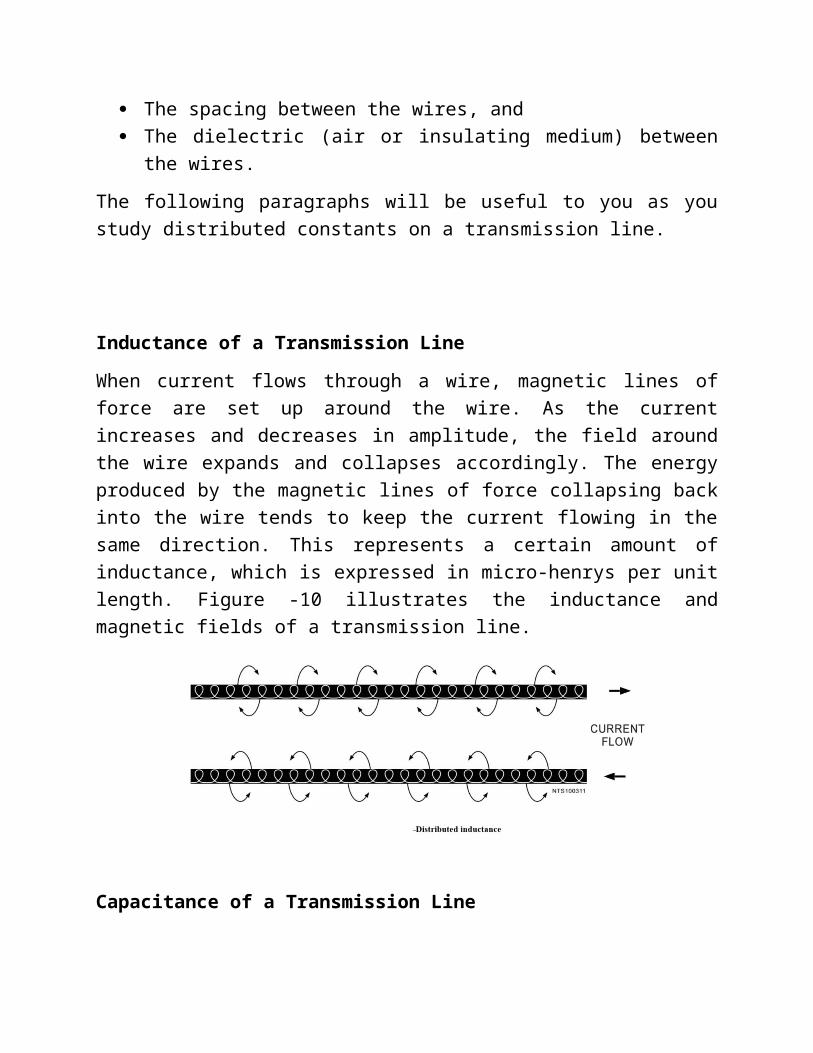
Inductance of a Transmission Line
When current flows through a wire, magnetic lines of force are set up around the wire. As the current increases and decreases in amplitude, the field around the wire expands and collapses accordingly. The energy produced by the magnetic lines of force collapsing back into the wire tends to keep the current flowing in the same direction. This represents a certain amount of inductance, which is expressed in micro-henrys per unit length. Figure -10 illustrates the inductance and magnetic fields of a transmission line.
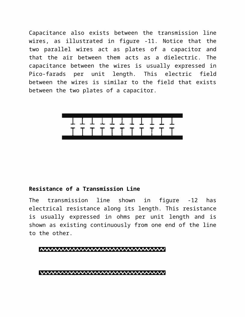
Capacitance of a Transmission Line
Capacitance also exists between the transmission line wires, as illustrated in figure -11. Notice that the two parallel wires act as plates of a capacitor and that the air between them acts as a dielectric. The capacitance between the wires is usually

expressed in Pico-farads per unit length. This electric field between the wires is similar to the field that exists between the two plates of a capacitor.
Resistance of a Transmission Line
The transmission line shown in figure -12 has electrical resistance along its length. This resistance is usually expressed in ohms per unit length and is shown as existing continuously from one end of the line to the other.
Leakage Current
Since any dielectric, even air, is not a perfect insulator, a small current known as LEAKAGE CURRENT flows between the two wires. In effect, the insulator acts as a resistor, permitting current to pass between the two wires. Figure -13 shows this leakage path as resistors in parallel connected between the two lines. This property is called CONDUCTANCE (G) and is the opposite of resistance.
Conductance in transmission lines is expressed as the reciprocal of resistance and is usually given in micro-mhos per unit length.

ELECTROMAGNETIC FIELDS ABOUT A TRANSMISSION LINE
The distributed constants of resistance, inductance, conductance and capacitance are basic properties common to all transmission lines and exist whether or not any current flow exists. As soon as current flow and voltage exist in a transmission line, another property becomes quite evident. This is the presence of an electromagnetic field, or lines of force, about the wires of the transmission line. The lines of force themselves are not visible; however, understanding the force that an electron experiences while in the field of these lines is very important to your understanding of energy transmission.
There are two kinds of fields; one is associated with voltage and the other with current. The field associated with voltage is called the ELECTRIC (E) FIELD. It exerts a force on any electric charge placed in it. The field associated with current is called a MAGNETIC (H) FIELD, because it tends to exert a force on any magnetic pole placed in it. Figure -14 illustrates the way in which the E fields and H fields tend to orient themselves between conductors of a typical two-wire transmission line. The illustration shows a cross section of the transmission lines. The E field is represented by solid lines and the H field by dotted lines. The arrows indicate the direction of the lines of force. Both fields normally exist together and are spoken of collectively as the electromagnetic field.

VELOCITY OF WAVE PROPAGATION
If a voltage is initially applied to the sending end of a line, that same voltage will appear later some distance from the sending end. This is true regardless of any change in voltage, whether the change is a jump from zero to some value or a drop from some value to zero. The voltage change will be conducted down the line at a constant rate.
Recall that the inductance of a line delays the charging of the line capacitance. The velocity of propagation is therefore related to the values of L and C. If the inductance and capacitance of the RF line are known, the time required for any waveform to travel the length of the line can be determined. To see how this works, observe the following relationship:
Q = IT
This formula shows that the total charge or quantity is equal to the current multiplied by the time the current flows. Also:
Q = CE
This formula shows that the total charge on a capacitor is equal to the capacitance multiplied by the voltage across the capacitor.

If the switch in figure is closed for a given time, the quantity (Q) of electricity leaving the battery can be computed by using the equation Q = IT. The electricity leaves the battery and goes into the line, where a charge is built up on the capacitors. The amount of this charge is computed by using the equation Q = CE.
Since none of the charge is lost, the total charge leaving the battery during T is equal to the total charge on the line. Therefore:
Q = IT = CE
As each capacitor accumulates a charge equal to CE, the voltage across each inductor must change. As C1 in figure charges to a voltage of E, point A rises to a potential of E volts while point B is still at zero volts. This makes E appear across L2. As C2 charges, point B rises to a potential of E volts as did point A.
At this time, point B is at E volts and point C rises. Thus, we have a continuing action of voltage moving down the infinite line.
In an inductor, these circuit components are related, as shown in the formula:
E=L¿)
This shows that the voltage across the inductor is directly proportional to inductance and the change in current, but inversely proportional to a change in time. Since current and time start from zero, the change in time (∆T) and the change in current (∆I) are equal to the final time (T) and final current (I). For this case the equation becomes:
ET = LI
If voltage E is applied for time (T) across the inductor (L), the final current (I) will flow. The following equations show how the three terms (T, L, and C) are related:
IT = EC
ET=LI

For convenience, you can find T in terms of L and C in the following manner. Multiply the left and right member of each equation as follows:
T=√ LC
This final equation is used for finding the time required for a voltage change to travel a unit length, since L and C are given in terms of unit length. The velocity of the waves may be found by:
V= DT
Or V= D√ LC
Where: D is the physical length of a unit
This is the rate at which the wave travels over a unit length. The units of L and C are henrys and farads, respectively. T is in seconds per unit length and V is in unit lengths per second.
Remember:
f = 1T
So = 1√ LC
* We have IT = EC and ET=LI, solving for E/I we have Characteristic
impedance =EI=Z0=√
LC .
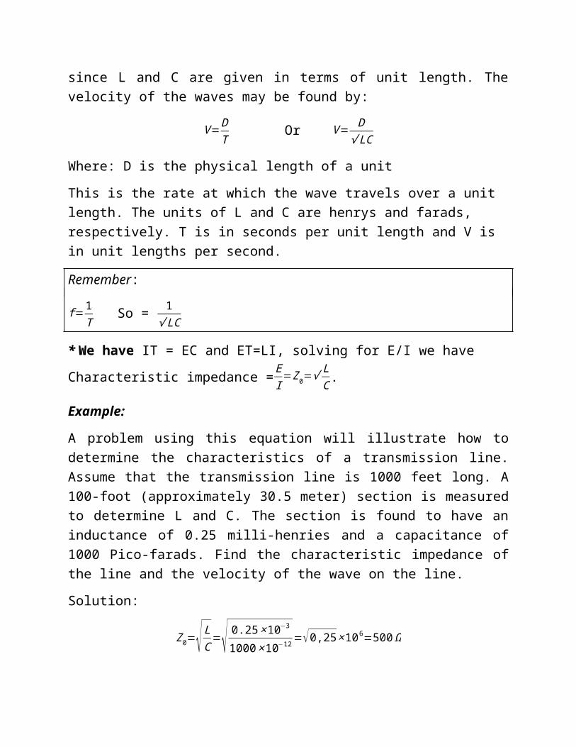
Example:
A problem using this equation will illustrate how to determine the characteristics of a transmission line. Assume that the transmission line is 1000 feet long. A 100-foot (approximately 30.5 meter) section is measured to determine L and C. The section is found to have an inductance of 0.25 milli-henries and a capacitance of 1000 Pico-farads. Find the characteristic impedance of the line and the velocity of the wave on the line.
Solution:
Z0=√ LC
=√ 0.25× 10⁻³
1000 ×10−12=√0,25 ×106=500 Ω
T=√ LC=√ 0.25× 10−3 ×1000 ×10−12=√o .25 ×10−12=0.5 ×10−6= 0,5 microsecond.

v=DT
= 30.5
5 OO ×10−9= 0.06 ×109=0,6 ×10⁸ M / S
Traveling Waves:
When a sine wave is applied to an infinitely long transmission line, the wave will propagate along the line. As shown, this wave at three successive instants in time. The voltage wave on a uniform, lossless transmission line is always accompanied by a current wave of similar shape, and, regardless of their shape, the two waves will be propagated without any change in magnitude or shape. These waves have definite electrical characteristics. The length of the wave λ is defined as the distance between successive points which have the same electrical phase.
This wavelength depends upon the frequency of variation of the wave and the dialectical constant (a physical characteristics of the medium) of the medium through which the wave is traveling. In free space a wave will travel with a velocity of approximately c=3× 10⁸ meters per second.
However, in a medium other than free space, the velocity will be reduced by the
factor1
√ ϵr. Where: ϵ r is the relative dialectical constant of the medium.
For practical purposes the relative dielectric constant of the air can be considered to be unity.
The following formula shows the relationship between the various factors which determine wavelength:
λ= 1√ ϵ r
.cf
Where;
c = velocity of propagation in free apace
f = frequancy of osillation
ϵ r = relative dielectric constant of the medium the wave is traviling in.
Wavelenght can be also be defined as the distance in which the phase changes by 2 π radins , where 2 π radins = 3600.
Example:
A distortion less line has Zo = 60 ohm, v = 0.6 c, where c is the speed of light in a vacuum. Find the wavelength at 100 MHz?
Solution: λ= vf = 0.6 ×3 108
100 ×106 =1.8m
Example:
A 50 ohm line of length 10 m is terminated by a 25 ohm load resistor. The line is connected to a 100MHz signal generator that has an output impedance of 50 ohms. The ϵ rof the line is 1.5. What will be the speed of propagation and the wavelength of the signal?
Solution:
v= c√ ϵ r
=3 ×10⁸
√ 1.5=2.45 × 10⁸m/s
λ= vf=2.45× 10⁸
100× 106 =2,45 m
Transmission Modes
Associated electric and magnetic fields are formed as voltage and current waves travels down a transmission line. Since these fields
are the result of voltage and current waves, which are periodical, the electric and magnetic waves also vary in aperiodic manner.
As propagation frequency increases, an appreciable portion of the wavelength of that propagation signal becomes comparable to the cross-sectional geometry of the transmission line, more than one kind of electromagnetic field configuration can be imagined.
As the frequency increases, more and more different types of propagation modes can exist on a certain transmission line.
If propagation frequency increases to infinity, an infinite number of propagation modes can exist. These modes are so called high order modes of propagation.
The principal mode is the one can carry energy at all frequencies. Higher order modes are those that propagate only above a definite frequency range. The point at which these frequencies start to propagate is called the cutoff frequency for that particular mode.
TEM principle mode:
At any point in space, the electric and the magnetic field lines are perpendicular to each other, and transverse to the direction of propagation. In other words no either electric or magnetic field align in the direction of propagation. That is why these waves, in the principle mode are called transverse electromagnetic waves or TEM mode of propagation.

Now, if the propagation frequency increases so much that the length of the wave traveling down the transmission line is comparable in size to the cross-sectional geometry of that transmission line, higher order modes can propagate. These higher order modes will have at least one of their field component shows in the direction of propagation.
Depending on which component shows in the in the direction of propagation, it will be called the H or E wave of propagation.
The H-wave is that in which at least one component of the magmatic field shows in the direction of propagation, this mode is called the transvers electric mode TE mode.
The E-wave is that in which at least one component of the electric field shows in the direction of propagation, this mode is balled the transvers magnetic mode TM mode.
The number of these modes on a transmission line is infinite, dependent entirely upon the geometry of the transmission line and the frequency used.
The velocity of propagation of the TE and TM modes is different from that of the TEM. In fact, two kinds of velocities can be imagined: group velocity and phase velocity.
Group velocity means the velocity of the entire group moving down in the transmission line, and phase velocity includes all rotations and turns of the individual moving particles.
Generally, in the TEM (principle mode), phase and group velocities are identical to each other.
In standard transmission line with no dielectric material around it, they would move with exactly the velocity of light = 300000000 m/s.
In higher order modes, group velocity and phase velocity related to each other by the following equation:
c=free space velocity=√ vg v p
Where:
vgis the group velocity
v pis the phase velocity

…………………………………………………………………………………
Review questions:
1. How would you express the characteristic impedance and the signal velocity of a loss free transmission line in terms of the distributed component model?
Answer:
Zo=√ LC Ω
V= DT Or V= D
√ LC
Where: D is the physical length of a unit.…………………………………………………………………………………….
2. Define Transmission line.
Answer:
Transmission line is a conductive method of guiding electrical energy from a source component to a load component. A transmission line is also known as feeder. (Or) A transmission line is a conducting line designed to guide electrical energy from one point to another point.
………………………………………………………………………………………
3. State the various types of transmission lines used in practice.
Answer:
The various types of transmission lines used are,
1. Parallel line 2. Twisted Pair line 3. Shielded Pair 4. Coaxial cable
5. Waveguide
……………………………………………………………………………………….
4. What are the primary constants of transmission line?
Answer:

The primary constants of a transmission line are:
1. Resistance (R)
2. Inductance (L)
3. Capacitance (C)
4. Conductance (G)
…………………………………………………………………………………..
5. Define the line parameters or primary constants of transmission line.
Answer:
The line parameters of transmission line are, R, L, C, G
Resistance (R) is defined as the loop resistance per unit length of the wire. Its unit is ohm/Km.
Inductance (L) is defined as the loop Inductance per unit length of the wire. Its unit is Henry/Km
Capacitance (C) is defined as the loop capacitance per unit length of the wire. Its unit is Farad/Km
Conductance (G) is defined as the loop conductance per unit length of the wire. Its unit is mho/Km
……………………………………………………………………………..
6. What is the difference between lumped parameters and distributed parameters?
Answer:
The parameters like Resistance, Inductance, capacitance which is physically separable are called as lumped parameters. In transmission lines, the parameters like Resistance, Inductance, and capacitance are distributed along the length of the line. They are not physically separable.
………………………………………………………………………………..
Sheet No 3

1. Assume that the transmission line is 1000 feet long. A 100-foot (approximately 30.5 meter) section is measured to determine L and C. The section is found to have an inductance of 0.25 milli-henries and a capacitance of 1000 Pico-farads. Find the characteristic impedance of the line and the velocity of the wave on the line?
Solution:
• Z0=√ LC
=√ 0.25× 10⁻³
1000 ×10−12=√0,25 ×106=500 Ω
• T=√ LC=√ 0.25× 10−3 ×1000 ×10−12=√o .25 ×10−12=0.5 ×10−6= 0,5 microsecond.
• v=DT
= 30.5
5 OO ×10−9 = 0.06 ×109=0.6 ×10⁸ M / S
2. Assume that the transmission line is 1000 feet long have characteristic impedance of 500 ohm and the velocity of the wave on the line is0.6 × 108 M / S . A 100-foot (approximately 30.5 meter) section is measured to determine L and C. . Find the capacitance and inductance of this section?
Solution:
• Z0=√ LC
=¿ 500 Ω
• T=√ LC=¿.
• v=DT
=0.6 ×10⁸ M /S where D = 30.5 mSolve for L and C
L= 0. 25 m heniry and C = 1000 Pico-farad
3. A 50 ohm line of length 10 m is terminated by a 25 ohm load resistor. The line is connected to a 100MHz signal generator that has an output impedance of 50 ohms. The ϵ rof the line

is (1.5). What will be the speed of propagation and the wavelength of the signal?
Solution:
• v= c√ ϵ r
=3 ×10⁸
√ 1.5=2.45 × 10⁸
m/s
• λ= vf=2.45× 10⁸
100× 106 =2.45 m
4. A nearly lossless transmission line (R is very small) has a unit length inductance of 3.75 nH and a unit length capacitance of 1.5 pF. Find the characteristic impedance Zo.
Solution:
Zo=√LC =√ 3.75 × 10⁻⁹
1.5 ×10⁻¹²
❑
= √2.5 ×103=¿ 50 ohm 1. What are the physical factors that determine the values of capacitance and
inductance of a transmission line?
Answer:
The physical factors that determine the values of capacitance and inductance of a transmission line are:
(1)Type of line used, (2)dielectric in the line, and (3)Length of line.
…………………………………………………………………………………..
2. What are the three types of line losses associated with transmission lines?
Answer:
Copper, dielectric, and radiation losses
…………………………………………………………………………………….
3. Describe the leakage current in a transmission line and in what unit it is expressed?
Answer:
The small amount of current that flows through the dielectric between two wires of a transmission line and is expressed in micro-mhos per unit length.
…………………………………………………………………………………………….
4. Losses caused by skin effect ( i2 R ) loss are classified as Copper losses, How
can we minimizing copper losses in RF Coaxial line?
Answer:
By plating the line with silver because silver is a better conductor than copper,
most of the current will flow through the silver layer.
…………………………………………………………………………………………………..
5. All the power sent down a transmission line from a transmitter can be transferred to an antenna under what optimum conditions?
Answer:
When the characteristic impedance of the transmission line and the load impedance
are equal.
………………………………………………………………………………………
6. What is the difference between lumped parameters and distributed
parameters?
When reflection occurs in a transmission line?
Answer:
The parameters like Resistance, Inductance, capacitance which is physically
separable are called as lumped parameters. In transmission lines, the parameters
like Resistance, Inductance, and capacitance are distributed along the length of the
line. They are not physically separable.
……………………………………………………………………………………
7. How would you express the characteristic impedance and the signal velocity of a loss free transmission line in terms of the distributed component model?

Answer:
Zo=√ LC Ω
V= DT Or V= D
√ LC
Where: D is the physical length of a unit.……………………………………………………………………………