Principles of Radar Systems, 3-1 CW Radar and the … Radar and the Doppler Effect Exercise 3-1...
21
© Festo Didactic 38542-00 135 When you have completed this exercise, you will be familiar with the principles of CW radar and the Doppler effect. You will be able to observe and quantify the frequency components associated with the Doppler effect. The Discussion of this exercise covers the following points: The Doppler effect Operating principles of a CW radar The Doppler effect The Doppler effect is the change in the frequency of a signal that occurs when the source and the observer are in relative motion, or when the signal is reflected by a moving object. There is an increase in frequency as the source and the observer (or the reflecting object) approach, and a decrease in frequency as they separate. A very common illustration of the Doppler effect is the shift in frequency a person hears when standing near the path of a moving sound source, such as an automobile horn, a train whistle, or a vehicle with a siren. While the source is approaching the person, the tone heard is shifted up in frequency. At the moment the source passes the person, the tone is heard at its actual frequency. As the source recedes, the tone heard is shifted down in frequency. The greater the speed of the vehicle, the greater the frequency shift. The Doppler effect is the basis of CW radar and allows the radar to measure the speed of a distant target. When the radar signal is reflected by a moving target, the echo signal is shifted up or down in frequency, depending on the direction of motion. The greater the speed of the target, the greater the frequency shift. This effect is also present in pulse radar. The Doppler effect is expressed by the equation: ൌ ௧ േ ௗ (3-1) where is the frequency of the received signal. ௧ is the frequency of the transmitted signal. ௗ is the Doppler frequency (the shift in frequency due to relative motion). The sign of the Doppler frequency depends on the direction of motion (+ for a closing target, í for an opening target). CW Radar and the Doppler Effect Exercise 3-1 EXERCISE OBJECTIVE DISCUSSION OUTLINE DISCUSSION
Transcript of Principles of Radar Systems, 3-1 CW Radar and the … Radar and the Doppler Effect Exercise 3-1...

© Festo Didactic 38542-00 135
When you have completed this exercise, you will be familiar with the principles of CW radar and the Doppler effect. You will be able to observe and quantify the frequency components associated with the Doppler effect.
The Discussion of this exercise covers the following points:
The Doppler effect
Operating principles of a CW radar
The Doppler effect
The Doppler effect is the change in the frequency of a signal that occurs when the source and the observer are in relative motion, or when the signal is reflected by a moving object. There is an increase in frequency as the source and the observer (or the reflecting object) approach, and a decrease in frequency as they separate.
A very common illustration of the Doppler effect is the shift in frequency a person hears when standing near the path of a moving sound source, such as an automobile horn, a train whistle, or a vehicle with a siren. While the source is approaching the person, the tone heard is shifted up in frequency. At the moment the source passes the person, the tone is heard at its actual frequency. As the source recedes, the tone heard is shifted down in frequency. The greater the speed of the vehicle, the greater the frequency shift.
The Doppler effect is the basis of CW radar and allows the radar to measure the speed of a distant target. When the radar signal is reflected by a moving target, the echo signal is shifted up or down in frequency, depending on the direction of motion. The greater the speed of the target, the greater the frequency shift. This effect is also present in pulse radar.
The Doppler effect is expressed by the equation:
(3-1)
where is the frequency of the received signal. is the frequency of the transmitted signal. is the Doppler frequency (the shift in frequency due to relative
motion).
The sign of the Doppler frequency depends on the direction of motion (+ for a closing target, for an opening target).
CW Radar and the Doppler Effect
Exercise 3-1
EXERCISE OBJECTIVE
DISCUSSION OUTLINE
DISCUSSION

Ex. 3-1 – CW Radar and the Doppler Effect Discussion
136 © Festo Didactic 38542-00
The cause of the frequency shift, when the target is moving relative to the radar, is the continuous change in the round-trip transit time (the time the waves take to travel from the radar to the target and back). When there is no relative movement, the round-trip distance is constant. Therefore, each wavefront, or crest, transmitted takes the same time to travel from the radar to the target and back to the radar. The frequency of the received wave is the same as that of the transmitted wave.
When the target is approaching the radar (closing), the round-trip distance is constantly decreasing. Each wavefront travels a slightly shorter distance than the previous wavefront. Each wavefront therefore takes slightly less time than the previous one to travel to the target and return to the radar as an echo. As a result, wavefronts are received at a slightly higher frequency than they are transmitted. If the target is receding from the radar (opening), the frequency of the received wavefronts is slightly lower than that of the transmitted signal.
Figure 3-3 illustrates the Doppler effect in terms of a change in wavelength. This figure shows a radar antenna and a moving target. The target is approaching the radar (closing) at a velocity . (This figure is not drawn to scale.)
Figure 3-3a shows a CW radar signal being transmitted towards the target. For clarity, only three wavefronts are shown. The distance between wavefronts in the
transmitted signal is the wavelength . The time between wavefronts is the period of the transmitted signal.
Wavefront A is the first to strike the target (Figure 3-3b). Part of this wavefront is reflected by the target back towards the radar as wavefront A'.
Wavefront B reaches the target one period later (Figure 3-3c). By this time,
however, the range has decreased by an amount equal to the target velocity times the period (The distance is greatly exaggerated in the figure). Part of wavefront B is reflected as wavefront B'. Because the range has been reduced by , the round-trip distance travelled by wavefront B B' is less than that travelled by wavefront A A'.
When wavefront C strikes the target (Figure 3-3d), the round-trip distance has
again decreased by . The distance between the reflected wavefronts as they travel back to the radar (Figure 3-3e) is therefore:
(3-2)
where is the wavelength of received signal. is the wavelength of the transmitted signal.
is the target velocity. is the period of the transmitted signal.
As a result of the Doppler effect, the wavelength of the echo signal is less than
the wavelength of the transmitted signal . This corresponds to an upward shift in frequency. The change in wavelength .

Ex. 3-1 – CW Radar and the Doppler Effect Discussion
© Festo Didactic 38542-00 137
Figure 3-3. The Doppler Effect.
For example, a police radar transmitting at 10 GHz detects a car moving directly towards the radar at a velocity of 30 m/s (approximately 100 km per hour). To find the transmitted wavelength, recall that the speed of propagation of a wave (in this case, the speed of light) is equal to the frequency times the wavelength. The transmitted wavelength is therefore:

Ex. 3-1 – CW Radar and the Doppler Effect Discussion
138 © Festo Didactic 38542-00
The change in wavelength for a closing target is:
This is an extremely small compression of the original wavelength. Because of the high frequency of the transmitted wave, however, it produces a measurable shift in frequency.
The Doppler frequency in this example could be calculated by substituting the change in wavelength into Equation (3-2), calculating the frequency of the received signal from the received wavelength, then subtracting the transmitted frequency. An easier method, however, is to consider the effect of target motion on the phase of the received signal.
If the distance between the radar and the target is , the total distance travelled by the wave is equal to . The number of wavelengths in the round-trip path
is , where and are in same units. The phase difference between the transmitted and received signal, in whole cycles is . Since one cycle radians, the phase radians.
If the target is moving towards or away from the radar, the range is constantly changing. The rate of change of the range is called the range rate, or radial velocity.
Because the range is changing, the phase of the received signal, with respect to the transmitted signal, is constantly changing. A steadily changing phase is equivalent to a shift in frequency. The Doppler frequency is equal to the time rate of change of the phase of the received signal:

Ex. 3-1 – CW Radar and the Doppler Effect Discussion
© Festo Didactic 38542-00 139
(3-3)
where is the Doppler frequency.
is the rate of change of the phase of the received signal.
is the wavelength of the transmitted signal.
is the range rate (R and t measured in the same units).
is the frequency of the transmitted signal. is the speed of light.
This formula is accurate providing the range rate is much less than the speed of light, which is usually the case.
Equation (3-3) can be used to determine the Doppler frequency in the preceding example of a police radar. Since, in this example, the target is moving along the line of sight of the radar, the range rate is equal to the velocity.
If the target is not moving directly towards or away from the radar, the range rate is not equal to the velocity. In fact, target movement perpendicular to the line of sight does not change the range at all. Also, the radar may itself be moving. The range rate is determined by both the relative velocity between the radar and the target, and the direction of motion:

Ex. 3-1 – CW Radar and the Doppler Effect Discussion
140 © Festo Didactic 38542-00
(3-4)
where
is the range rate.
is the relative velocity. is the angle between the direction of motion and the line of
sight. is the component of relative velocity along the line of sight.
By substituting Equation (3-4) into Equation (3-3), we obtain the general formula for the Doppler frequency:
where is the Doppler frequency.
is the frequency of the transmitted signal. is the speed of light. is the relative velocity.
is the angle between the direction of motion and the line of sight.
Returning to our example of a car moving at 30 m/s, if is zero, as in Figure 3-4a, the Doppler frequency 2 kHz, as previously calculated. If is 90°, as in Figure 3-4b, the trajectory is perpendicular to the line of sight, and
the Doppler frequency is zero. If is 45°, as in Figure 3-4c, then:

Ex. 3-1 – CW Radar and the Doppler Effect Discussion
© Festo Didactic 38542-00 141
Figure 3-4. Effect of direction on the Doppler frequency.
Operating principles of a CW radar
Figure 3-5 shows a block diagram of a simple CW radar. In this figure, a circulator allows using the same antenna for transmission and reception. Many CW radars, however, use separate antennas.
Figure 3-5. Simple CW radar block diagram.
Ex. 3-1 – CW Radar and the Doppler Effect Discussion
142 © Festo Didactic 38542-00
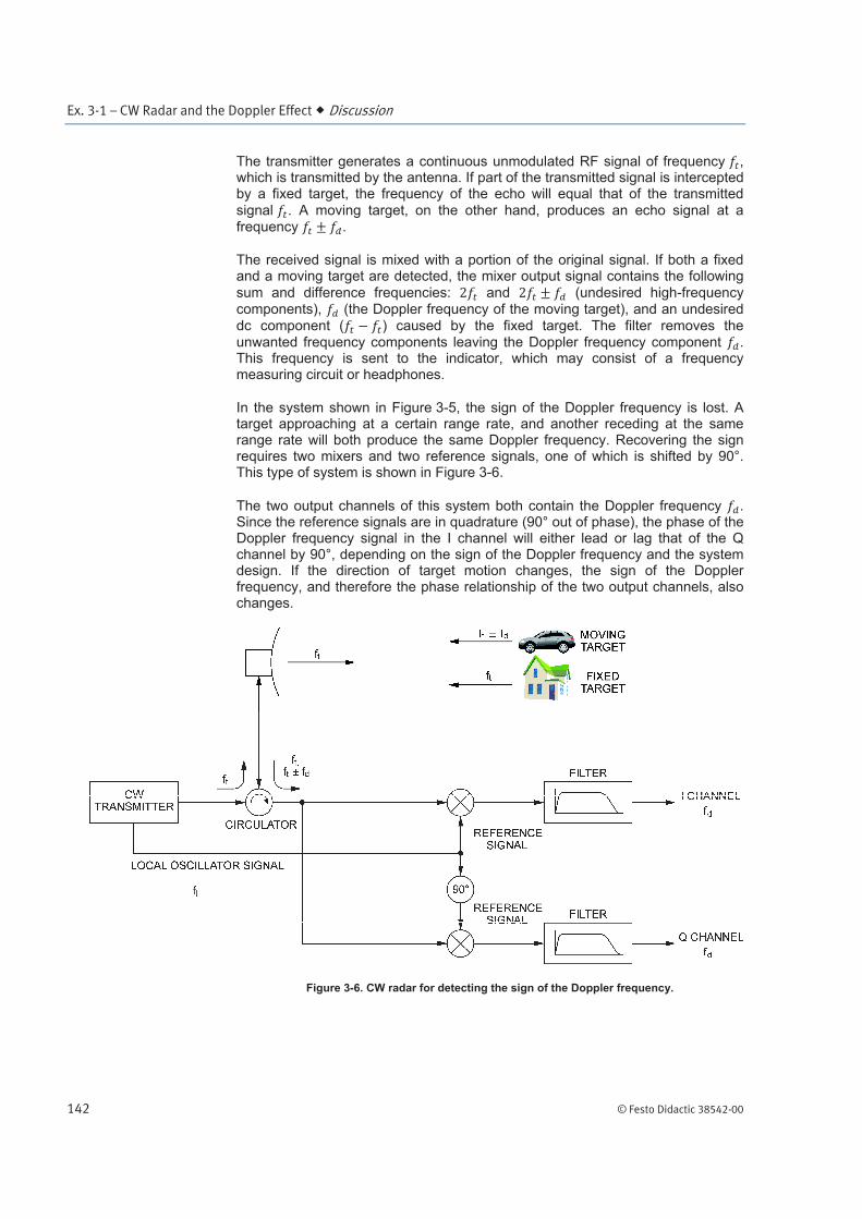
The transmitter generates a continuous unmodulated RF signal of frequency , which is transmitted by the antenna. If part of the transmitted signal is intercepted by a fixed target, the frequency of the echo will equal that of the transmitted
signal . A moving target, on the other hand, produces an echo signal at a frequency .
The received signal is mixed with a portion of the original signal. If both a fixed and a moving target are detected, the mixer output signal contains the following
sum and difference frequencies: and (undesired high-frequency components), (the Doppler frequency of the moving target), and an undesired
dc component ( ) caused by the fixed target. The filter removes the unwanted frequency components leaving the Doppler frequency component . This frequency is sent to the indicator, which may consist of a frequency measuring circuit or headphones.
In the system shown in Figure 3-5, the sign of the Doppler frequency is lost. A target approaching at a certain range rate, and another receding at the same range rate will both produce the same Doppler frequency. Recovering the sign requires two mixers and two reference signals, one of which is shifted by 90°. This type of system is shown in Figure 3-6.
The two output channels of this system both contain the Doppler frequency . Since the reference signals are in quadrature (90° out of phase), the phase of the Doppler frequency signal in the I channel will either lead or lag that of the Q channel by 90°, depending on the sign of the Doppler frequency and the system design. If the direction of target motion changes, the sign of the Doppler frequency, and therefore the phase relationship of the two output channels, also changes.
Figure 3-6. CW radar for detecting the sign of the Doppler frequency.

Ex. 3-1 – CW Radar and the Doppler Effect Procedure Outline
© Festo Didactic 38542-00 143
One way of determining the phase relationship of the two channels is to connect them across a synchronous two-phase motor. The direction of motor rotation indicates the phase relationship, and therefore the sign of the Doppler frequency. Electronic methods may also be used.
CW radar can be used wherever it is necessary to determine the radial velocity of a reflecting object. Some examples of applications for CW radar are police speed monitors, rate-of-climb meters for vertical-take-off aircraft, and systems for measuring railroad-car velocity in switching yards.
The Procedure is divided into the following sections:
Setting up the CW radar
The Doppler effect in CW radar
The concept of range rate
Determining target direction (approaching or receding)
Setting up the CW radar
In this section, you will set up a CW radar. The block diagram of the system you will use is shown in Figure 3-8.
1. The main elements of the Radar Training System, that is the antenna and its pedestal, the target table and the training modules, must be set up properly before beginning this exercise. Refer to Appendix B of this manual for setting up the Radar Training System, if this is not done yet.
Set up the modules on the Power Supply / Antenna Motor Driver as shown in Figure 3-7.
Figure 3-7. Module Arrangement.
On the Radar Transmitter, make sure that the RF POWER switch is in the STANDBY position.
On the Antenna Controller, make sure that the MANual ANTENNA ROTATION MODE is selected and that the SPEED control is in the 0 position.
PROCEDURE OUTLINE
PROCEDURE

Ex. 3-1 – CW Radar and the Doppler Effect Procedure
144 © Festo Didactic 38542-00
Set the POWER switch of the Power Supply to the I (on) position, and then those of the other modules.
2. Figure 3-8 shows the block diagram of the CW radar that can be obtained using the Radar Training System. Connect the modules according to this block diagram.
a Use a medium-length SMA cable (approximately 75 cm) to connect the RF OSCILLATOR OUTPUT of the Radar Transmitter to the LOCAL OSCILLATOR INPUT of the Radar Receiver.
Figure 3-8. Block diagram of the CW radar.
3. Connect the cable of the target table to the multi-pin connector located on the rear panel of the Target Controller. Make sure that the surface of the target table is free of any objects and then set the POWER switch of the Target Positioning System to the I (on) position.
Position the target table and the Rotating-Antenna Pedestal as shown in Figure 3-9. Make sure that the near corner of the target table is located approximately 1.5 m from the Rotating-Antenna Pedestal, and that the diagonal of the target table grid is correctly aligned with the shaft of the Rotating-Antenna Pedestal.

Ex. 3-1 – CW Radar and the Doppler Effect Procedure
© Festo Didactic 38542-00 145
Figure 3-9. Position of the Rotating-Antenna Pedestal and target table.
Place the large metal plate target on the mast of the target table. Orient the target so that it faces the Rotating-Antenna Pedestal, then tighten the screw to secure the target to the mast.
4. On the Target Controller, make sure that the TRAJECTORY SPEED control is in the MINimum position and then make the following settings:
MODE ............................................................ TRAJECTORY TRAJECTORY ............................................... / DISPLAY MODE ............................................ SPEED
In the TRAJECTORY MODE, the trajectory of the target table movable carriage is selected using the TRAJECTORY SELECT push button, while its speed is set using the TRAJECTORY SPEED control. The TRAJECTORY LED should be lit to indicate that these controls are operational.
Set the TRAJECTORY SPEED control to maximum. Describe the target movement.

Ex. 3-1 – CW Radar and the Doppler Effect Procedure
146 © Festo Didactic 38542-00
The Doppler effect in CW radar
In this section, you will use a moving target, whose trajectory is aligned with the Radar Antenna beam axis, to observe the target echo signal at the CW DOPPLER OUTPUT of the Radar Receiver. You will determine the relationship between this signal and the target motion, and explain the phenomenon which is at the origin of this signal. You will measure the frequency of the CW DOPPLER OUTPUT signal for various combinations of the transmitted RF signal frequency and target speed. This will allow you to determine the relationship between these parameters.
5. On the Antenna Controller, use the SPEED control to align the antenna beam axis with the target trajectory.
On the Radar Transmitter, depress the VARiable FREQUENCY push button, then set the RF OSCILLATOR frequency to maximum. The RF OSCILLATOR FREQUENCY display should indicate 10.0 GHz.
Depress the RF POWER push button. The RF POWER ON LED should start to flash on and off. This indicates that RF power is being radiated by the Radar Antenna.
a Since the radiation levels of the Radar Training System are very low, there is no danger to anyone standing near or in front of the antenna. Remember however, that with a full-scale radar, you must always make sure that no one could be exposed to dangerous radiation levels before turning on the RF power.
6. Adjust the oscilloscope as follows:
Channel 1 ...................................................... 5 V/DIV (DC coupled) Vertical Mode ................................................. Channel 1 Time Base ...................................................... 20 ms/DIV Trigger ........................................................... Channel 1
Observe the CW DOPPLER OUTPUT signal of the Radar Receiver on the oscilloscope screen. Describe this signal.
Determine the relationship between the CW DOPPLER OUTPUT signal and the movement of the target.

Ex. 3-1 – CW Radar and the Doppler Effect Procedure
© Festo Didactic 38542-00 147
What phenomenon is at the origin of the CW DOPPLER OUTPUT signal? Explain.
7. On the Target Controller, set the TRAJECTORY SPEED control to minimum, then select the POSITION MODE.
Position the target table and the Rotating-Antenna Pedestal so that the grid of the target table is located approximately 2.0 m from the horn of the Radar Antenna, as shown in Figure 3-10. Make sure that the Radar Antenna beam axis is correctly aligned with the metal rail of the target table.
Set the orientation of the target so that it is perpendicular to the metal rail of the target table.
Figure 3-10. Position of the Rotating-Antenna Pedestal and target table.
8. Calculate the Doppler frequency corresponding to each combination of the
transmitted RF signal frequency and target speed given in Table 3-1. Note the results in the appropriate rows of the CALCULATED DOPPLER
FREQUENCY column of Table 3-1.
Ex. 3-1 – CW Radar and the Doppler Effect Procedure
148 © Festo Didactic 38542-00
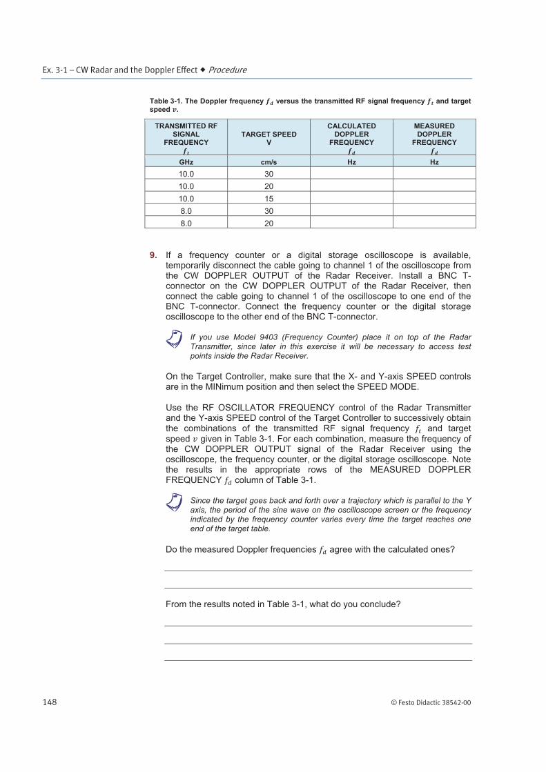
Table 3-1. The Doppler frequency versus the transmitted RF signal frequency and target
speed .
TRANSMITTED RF SIGNAL
FREQUENCY
TARGET SPEED V
CALCULATED DOPPLER
FREQUENCY
MEASURED DOPPLER
FREQUENCY
GHz cm/s Hz Hz
10.0 30
10.0 20
10.0 15
8.0 30
8.0 20
9. If a frequency counter or a digital storage oscilloscope is available, temporarily disconnect the cable going to channel 1 of the oscilloscope from the CW DOPPLER OUTPUT of the Radar Receiver. Install a BNC T-connector on the CW DOPPLER OUTPUT of the Radar Receiver, then connect the cable going to channel 1 of the oscilloscope to one end of the BNC T-connector. Connect the frequency counter or the digital storage oscilloscope to the other end of the BNC T-connector.
a If you use Model 9403 (Frequency Counter) place it on top of the Radar Transmitter, since later in this exercise it will be necessary to access test points inside the Radar Receiver.
On the Target Controller, make sure that the X- and Y-axis SPEED controls are in the MINimum position and then select the SPEED MODE.
Use the RF OSCILLATOR FREQUENCY control of the Radar Transmitter and the Y-axis SPEED control of the Target Controller to successively obtain the combinations of the transmitted RF signal frequency and target
speed given in Table 3-1. For each combination, measure the frequency of the CW DOPPLER OUTPUT signal of the Radar Receiver using the oscilloscope, the frequency counter, or the digital storage oscilloscope. Note the results in the appropriate rows of the MEASURED DOPPLER FREQUENCY column of Table 3-1.
a Since the target goes back and forth over a trajectory which is parallel to the Y axis, the period of the sine wave on the oscilloscope screen or the frequency indicated by the frequency counter varies every time the target reaches one end of the target table.
Do the measured Doppler frequencies agree with the calculated ones?
From the results noted in Table 3-1, what do you conclude?
Ex. 3-1 – CW Radar and the Doppler Effect Procedure
© Festo Didactic 38542-00 149
The concept of range rate
In this section, you will use a moving target, whose trajectory is at an angle of 30° to the Radar Antenna beam axis, to introduce you to the concept of range rate. For a given combination of the transmitted RF signal frequency and target speed, you will measure the frequency of the CW DOPPLER OUTPUT signal and compare the result with that previously obtained using the same transmitted RF signal frequency and target speed.
10. On the Target Controller, use the Y-axis SPEED control to set the target speed to 0, then use the X-axis SPEED control to set the target speed to approximately 20 cm/s.
Observe on the oscilloscope screen that, except for some noise, there is no signal at the CW DOPPLER OUTPUT of the Radar Receiver, even though the target is moving in front of the Radar Antenna. Explain.
11. On the Target Controller, use the X-axis SPEED control to set the target speed to 0, then select the POSITION MODE.
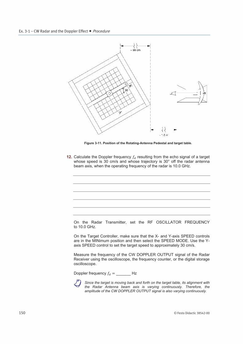
Position the target table and the Rotating-Antenna Pedestal as shown in Figure 3-11. Make sure that the near corner of the target table is located approximately 1.5 m from the Rotating-Antenna Pedestal, and that the metal rail of the target table is approximately 30° off the Radar Antenna beam axis. Make sure that the target remains aligned with the Radar Antenna beam axis.
Set the orientation of the target so that it faces the Radar Antenna.
Ex. 3-1 – CW Radar and the Doppler Effect Procedure
150 © Festo Didactic 38542-00
Figure 3-11. Position of the Rotating-Antenna Pedestal and target table.
12. Calculate the Doppler frequency resulting from the echo signal of a target whose speed is 30 cm/s and whose trajectory is 30° off the radar antenna beam axis, when the operating frequency of the radar is 10.0 GHz.
On the Radar Transmitter, set the RF OSCILLATOR FREQUENCY to 10.0 GHz.
On the Target Controller, make sure that the X- and Y-axis SPEED controls are in the MINimum position and then select the SPEED MODE. Use the Y-axis SPEED control to set the target speed to approximately 30 cm/s.
Measure the frequency of the CW DOPPLER OUTPUT signal of the Radar Receiver using the oscilloscope, the frequency counter, or the digital storage oscilloscope.
Doppler frequency Hz
a Since the target is moving back and forth on the target table, its alignment with the Radar Antenna beam axis is varying continuously. Therefore, the amplitude of the CW DOPPLER OUTPUT signal is also varying continuously.

Ex. 3-1 – CW Radar and the Doppler Effect Procedure
© Festo Didactic 38542-00 151
Compare the measured and calculated Doppler frequencies . What does this confirm?
Compare the Doppler frequencies obtained in this step with those noted in the first row of Table 3-1. In both cases, the transmitted RF signal frequency and the target speed are the same. Explain.
Determining target direction (approaching or receding)
In this section, you will use a moving target, whose trajectory is aligned with the Radar Antenna beam axis, to simultaneously observe the target echo signal at TP3 and TP5 of the Radar Receiver. You will determine the relationship between the direction of target motion (approaching or receding) and the phase relationship between the signals at TP3 and TP5.
13. On the Target Controller, use the Y-axis SPEED control to set the target speed to 0, then select the POSITION MODE.
Position the target table and the Rotating-Antenna Pedestal so that the grid of the target table is located approximately 2.0 m from the horn of the Radar Antenna, as shown in Figure 3-10. Make sure that the Radar Antenna beam axis is correctly aligned with the metal rail of the target table.
Set the orientation of the target so that it is perpendicular to the metal rail of the target table.
14. Remove the cable connecting the CW DOPPLER OUTPUT of the Radar Receiver to channel 1 of the oscilloscope.
Using probes, connect TP3 and TP5 of the Radar Receiver to channels 1 and 2 of the oscilloscope, respectively. The signals from TP3 and TP5 are produced by the I- and Q-channel MIXERS, respectively.
On the Target Controller, make sure that the X- and Y-axis SPEED controls are in the MINimum position and then select the SPEED MODE. Use the Y-axis SPEED control to set the target speed to approximately 30 cm/s.

Ex. 3-1 – CW Radar and the Doppler Effect Procedure
152 © Festo Didactic 38542-00
Adjust the oscilloscope as follows:
Channel 1 ...................................................... 0.2 V/DIV (DC coupled) Channel 2 ...................................................... 0.2 V/DIV (DC coupled) Vertical Mode ................................................. CHOP Time Base ...................................................... 10 ms/DIV Trigger ........................................................... Channel 1 Trigger Coupling ............................................ HF-REJ
Use the vertical position controls to place the signals coming from TP3 and TP5 of the Radar Receiver in the upper and lower halves of the oscilloscope screen, respectively. Figure 3-12 shows an example of what the signal from TP3 might resemble.
a The amplitude of the signals from TP3 and TP5 of the Radar Receiver increases as the target approaches the Radar Antenna, and vice versa.
Figure 3-12. Phase relationship between the signals from TP3 and TP5 of the Radar Receiver.

Ex. 3-1 – CW Radar and the Doppler Effect Conclusion
© Festo Didactic 38542-00 153
15. Observe the signals on the oscilloscope screen and the movement of the target (approaching or receding). Determine the relationship between the target movement and the phase relationship between the signals from TP3 and TP5 of the Radar Receiver.
On Figure 3-12a, draw the signal from TP5 of the Radar Receiver when the target is approaching the Radar Antenna.
Using Figure 3-12b, draw the signal from TP5 of the Radar Receiver when the target is receding of the Radar Antenna.
16. Make sure that TP3 and TP5 of the Radar Receiver are connected to the X and Y channels of the oscilloscope, respectively.
Set the oscilloscope in the X-Y mode. The trace on the oscilloscope screen should describe a circle, or an ellipse. Use the X- and Y-position controls to place the trace in the centre of the oscilloscope screen.
Describe the behaviour of the oscilloscope trace with respect to the target movement (approaching or receding).
What is the utility of this display?
17. On the Radar Transmitter, make sure that the RF POWER switch is in the STANDBY position. The RF POWER STANDBY LED should be lit. Place all POWER switches in the O (off) position and disconnect all cables and accessories.
In this exercise, you learned that the Doppler effect is the basis of the CW radar. You saw that the echo signal of a moving target is a sine wave whose frequency corresponds to the Doppler frequency shift. You verified that the Doppler
frequency is proportional to the transmitted RF signal frequency and to the range rate dR/dt. You verified that the target trajectory greatly influences the range rate. Finally, you performed a simple test for detecting the target direction (approaching or receding).
CONCLUSION

Ex. 3-1 – CW Radar and the Doppler Effect Review Questions
154 © Festo Didactic 38542-00
1. What is the Doppler effect?
2. How is the Doppler effect used in CW radar?
3. What causes the Doppler effect?
4. Calculate the frequency shift for an opening target whose trajectory is 15 off of the line of sight, and whose velocity is 100 m/s. The radar operates at 8.0 GHz.
REVIEW QUESTIONS
Ex. 3-1 – CW Radar and the Doppler Effect Review Questions
© Festo Didactic 38542-00 155
5. What is the function of the filter at the output of the CW receiver?