Principles and Operation of Sensors - Ampere Mé · PDF filePrinciples and Operation of...
56
Principles and Operation of Sensors Mexico City September 2016 Stuart Allardice Client Relationship Manager (Americas) Email: [email protected] Cell: +44 7775694200 Skype: stuart_allardice_gsl
Transcript of Principles and Operation of Sensors - Ampere Mé · PDF filePrinciples and Operation of...

Principles and Operation of Sensors
Mexico City September 2016
Stuart Allardice Client Relationship Manager
(Americas) Email: [email protected]
Cell: +44 7775694200Skype: stuart_allardice_gsl

Welcome!

Chris PottsExecutive Chairman
Gordon RiceOperations Director
Phil HillEngineering Director
Neil WatkissCommercial Director
GURALP Management Team
Chris LyddonChief Financial Officer

SALES
- Sales contact for each region- Increased Sales Support- Management restructure
Hannah PetersClient Relationship ManagerEMEA
Stephen HicksClient Relationship ManagerSouth Asia
Clare SweeneyClient Relationship ManagerAsia Pacific
Stuart AllardiceClient Relationship ManagerAmericas

Topics of Discussion
• Difference between broadband and short period
• Force feedback mechanism
• Sensor Component Orientation
• Dynamic Range
• Sensitivity
• Self Noise
• FBA vs MEMS
• Cross Axis Rejection
• Output Voltage
• Transient Protection

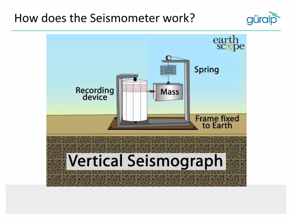
How does the Seismometer work?
How does the Seismometer work?

How does the Seismometer work?
The modern broadband seismograph can record a very broad range of frequencies. It consists of a small "proof mass", confined by electrical forces, driven by sophisticated electronics.
As the earth moves, the electronics attempt to hold the mass steady through a feedback circuit. The amount of force necessary to achieve this is then recorded.
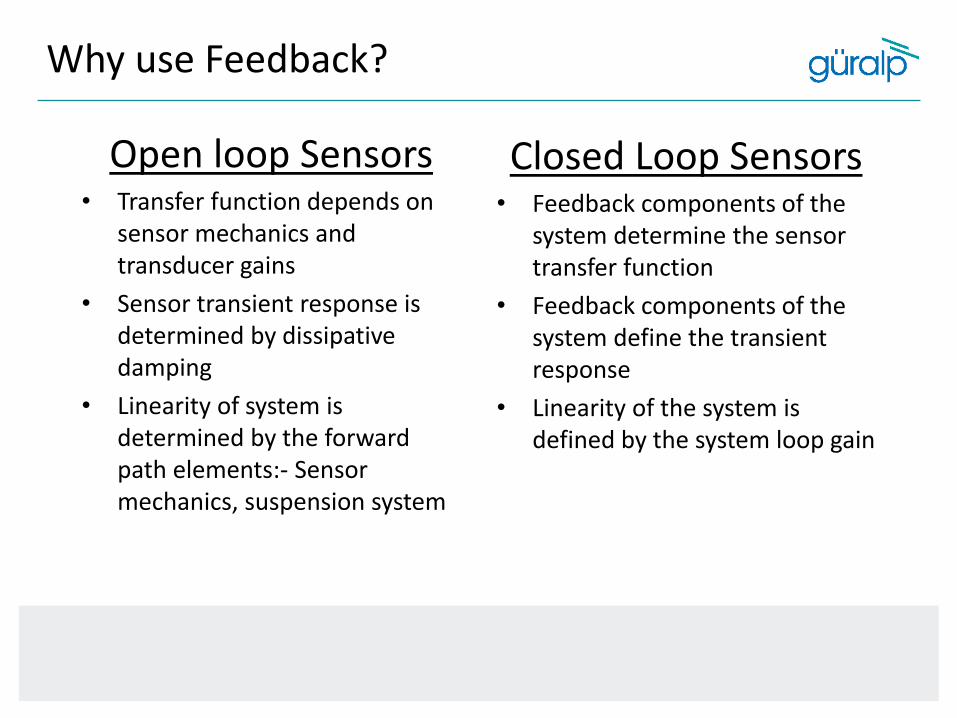
Why use Feedback?
Open loop Sensors• Transfer function depends on
sensor mechanics and transducer gains
• Sensor transient response is determined by dissipative damping
• Linearity of system is determined by the forward path elements:- Sensor mechanics, suspension system
Closed Loop Sensors• Feedback components of the
system determine the sensor transfer function
• Feedback components of the system define the transient response
• Linearity of the system is defined by the system loop gain

Difference between broadband and short period
What is the difference?

Broadband vs Short Period Sensor
360s 120s 60s 0.02s 0.01s 0.005s
0.003Hz 0.008Hz 0.016Hz 50Hz 100Hz 200Hz
λ
ƒ
Teleseismic Regional Local
3T
3ESPC
ESPC
40T
40T
6T
6T
Fortis
Fortis
Radian
3T
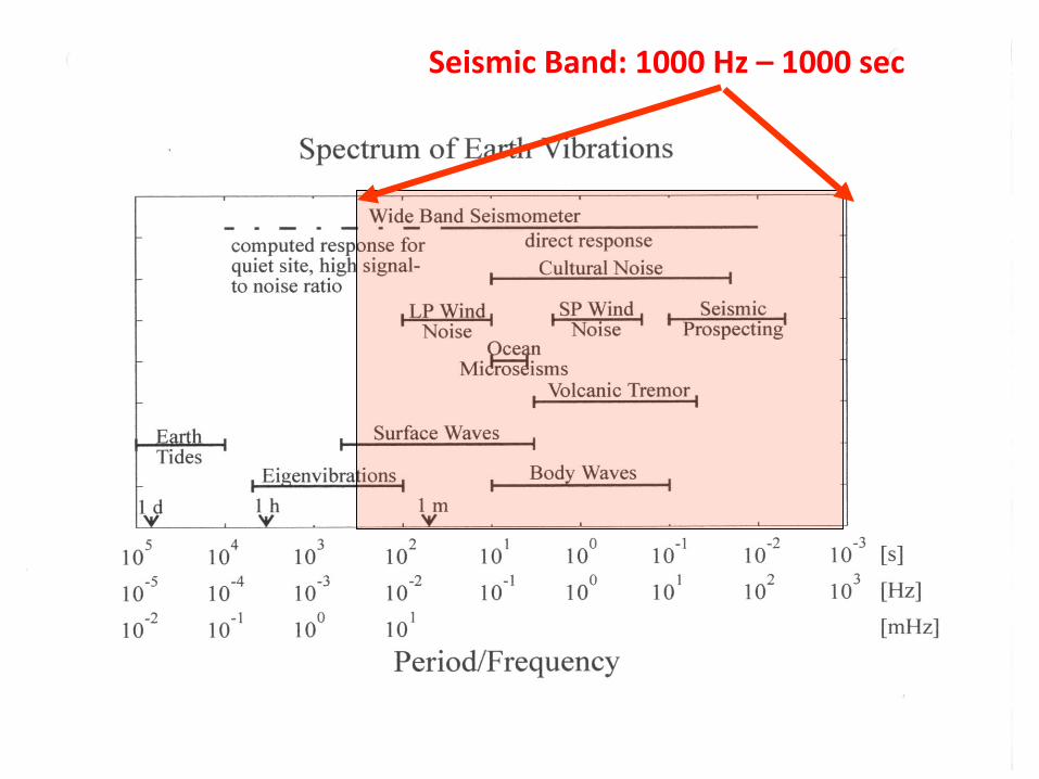
Seismic Band: 1000 Hz – 1000 sec

our sensors

GPS
Gravimeters
Tiltmeters
Strainmeters
Creepmeters
our broadband
sensors
GeophonesBarometersPiezoelectricTransducers
InfrasoundHydrophonesMicrophones
Limits are very flexible

Expected displacement spectra for events of different magnitude. A low frequency plateau is followed by a corner frequency, after which displacement drops away. This corner must be accurately measured to generate robust magnitude estimates. 15Hz and/or 4.5Hz geophones do not accurately record corner frequencies for larger events, leading to systematic magnitude underestimates. A broadband instrument is required to record event magnitudes accurately (Viegas et al., 2012).
Broadband vs Short Period Sensor

Broadband vs Short Period Sensor
Waveforms (top) and displacement spectra (bottom) for the same event recorded on 3 different sensors: an accelerometer with broadband response (left), a 4.5Hz geophone (middle) and a 15Hz geophone (right). The broadband sensor accurately measures a magnitude of 1.8 while the 4.5 and 15Hz phones measure 1.5 and 1.2 respectively (Viegas et al., 2012).

Dynamic Range
Dynamic Range defines the intensity from the lowest to the highest amplitude which
can be recorded.
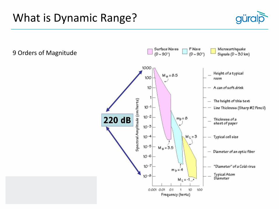
What is Dynamic Range?
9 Orders of Magnitude

Dynamic Range
The Dynamic Range of a sensor is fixed
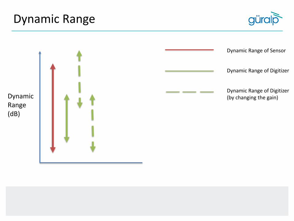
Dynamic Range of Sensor
Dynamic Range of Digitizer
Dynamic Range of Digitizer (by changing the gain)
Dynamic Range
Dynamic Range (dB)
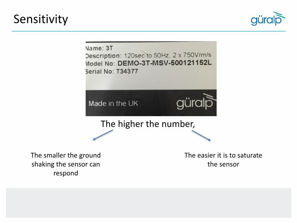
The higher the number,
The smaller the ground shaking the sensor can
respond
The easier it is to saturate the sensor
Sensitivity

Sensitivity
Why do we change the sensitivity of the sensor?

Sensitivity = defines the output voltage of a sensor response to shaking of a known velocity/acceleration
For velocity instruments this is measured in V / m / sFor acceleration instruments this is measured in V / m / s 2
Sensitivity
How is it related?

Clvel = Vmax / S [m/sec]
Sensitivity
Clip Level Velocity:
Where Vmax is the peak output voltage of the seismometer. For all modern broadband seismometers S is constant across the flat response of the instrument.
Sensitivity
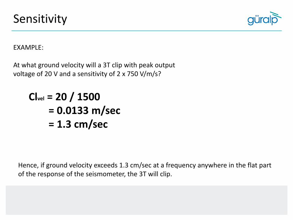
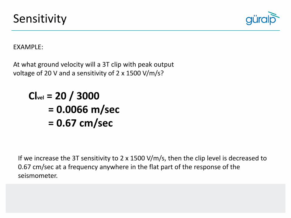
EXAMPLE:
At what ground velocity will a 3T clip with peak output voltage of 20 V and a sensitivity of 2 x 750 V/m/s?
Clvel = 20 / 1500= 0.0133 m/sec= 1.3 cm/sec
Hence, if ground velocity exceeds 1.3 cm/sec at a frequency anywhere in the flat part of the response of the seismometer, the 3T will clip.
Sensitivity
EXAMPLE:
At what ground velocity will a 3T clip with peak output voltage of 20 V and a sensitivity of 2 x 1500 V/m/s?
Clvel = 20 / 3000= 0.0066 m/sec= 0.67 cm/sec
If we increase the 3T sensitivity to 2 x 1500 V/m/s, then the clip level is decreased to 0.67 cm/sec at a frequency anywhere in the flat part of the response of the seismometer.

Sensitivity
EXAMPLE:
At what ground velocity will a 40T clip with peak output voltage of 20 V and a sensitivity of 2 x 200 V/m/s?
Clvel = 20 / 400= 0.05 m/sec= 5 cm/sec
If we decrease the sensitivity and use a 40T at 2 x 200 V/m/s, then the clip level is increased to 5 cm/sec at a frequency anywhere in the flat part of the response of the seismometer.

Sensitivity
CLAcc = Vmax * w/ S [m/sec2]
where the frequency w = 2p/T, and T is the
period of the ground acceleration.
When considering clip levels in acceleration it then becomes frequency dependent and can be expressed with the following equation:
Sensitivity
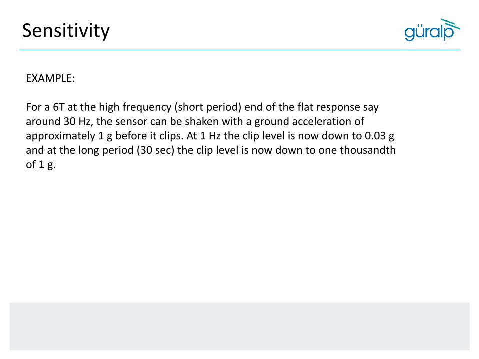
EXAMPLE:
For a 6T at the high frequency (short period) end of the flat response say around 30 Hz, the sensor can be shaken with a ground acceleration of approximately 1 g before it clips. At 1 Hz the clip level is now down to 0.03 g and at the long period (30 sec) the clip level is now down to one thousandth of 1 g.

Sensor Component Orientation
• Güralp are all truly orthogonal X Y Z orientation• Competitors have Symmetrical U V W orientation
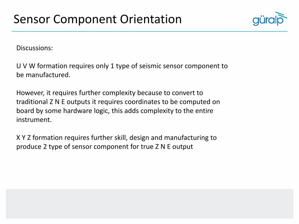
Discussions:
U V W formation requires only 1 type of seismic sensor component to be manufactured.
However, it requires further complexity because to convert to traditional Z N E outputs it requires coordinates to be computed on board by some hardware logic, this adds complexity to the entire instrument.
X Y Z formation requires further skill, design and manufacturing to produce 2 type of sensor component for true Z N E output
Sensor Component Orientation

Sensor Component Orientation
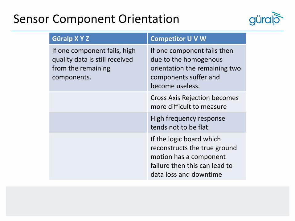
Güralp X Y Z Competitor U V W
If one component fails, high quality data is still received from the remaining components.
If one component fails then due to the homogenousorientation the remaining two components suffer and become useless.
Cross Axis Rejection becomes more difficult to measure
High frequency response tends not to be flat.
If the logic board which reconstructs the true ground motion has a component failure then this can lead to data loss and downtime
Sensor Component Orientation

Self-Noise
Rain Drops: Rain falls, hits the roof of the building, or road, or car and it makes noise.
The exact same thing is happening inside the sensor on a microscopic level!
What is Self-Noise?
Brownian Motion…
Self-Noise
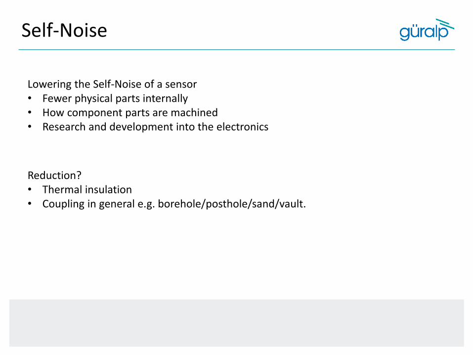
Reduction?• Thermal insulation• Coupling in general e.g. borehole/posthole/sand/vault.
Lowering the Self-Noise of a sensor • Fewer physical parts internally• How component parts are machined• Research and development into the electronics

Self-Noise
Bandwidth
What is the bandwidth of the sensor?

Bandwidth
0.01 0.1 1 10 100 1000Period [sec]
upper cornerfrequency
100 Hz
lower cornerfrequency
120 sec
linear and flat responsebetween the two corners

Bandwidth
You want 120 sec data?
Think about the size of the instrument.
Example: The mass
You could have two sensors that have 120 sec response but the performance difference can be significant.
Performance = Mass Size

FBA vs MEMS
Force Balanced Accelerometers vs Microelectromechanical Systems
In most designs the electronics holds a mass motionless relative to the frame. This device is called a "force balance accelerometer".
It measures acceleration instead of velocity of ground movement.
Basically, the distance between the mass and some part of the frame is measured very precisely, by a linear variable differential capacitor.
Main difference is the noise floor.
For the lower frequency events a MEMS will not provide the high quality data like a FBA will do.

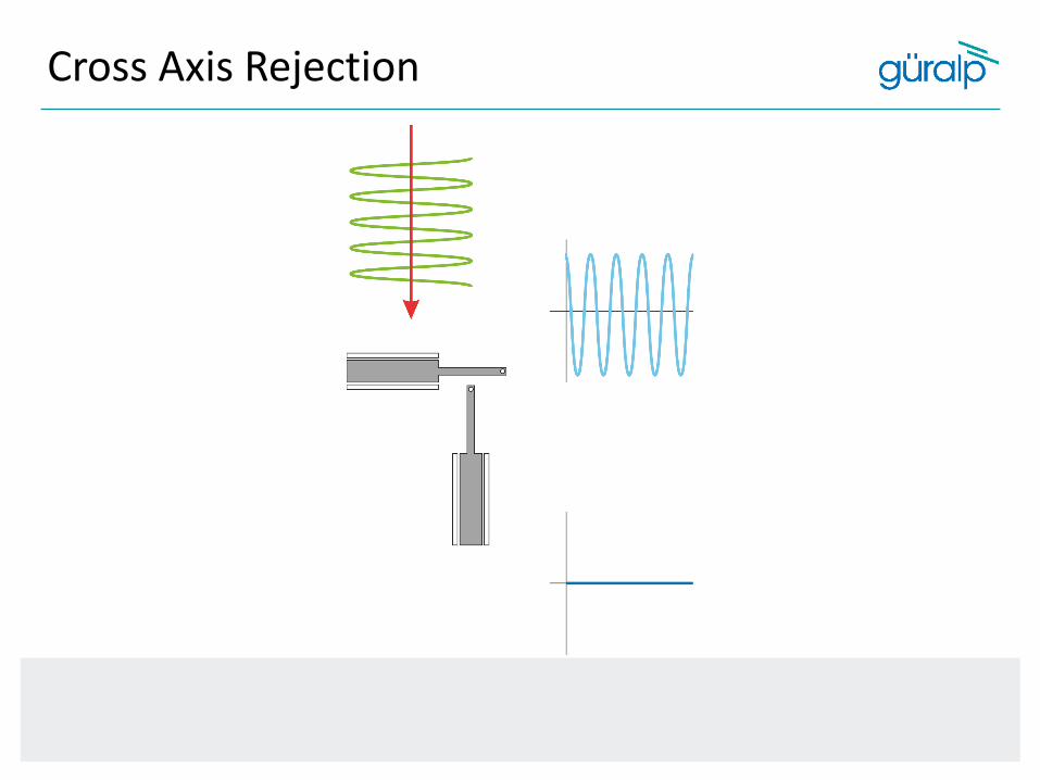
What is Cross Axis Rejection?
Cross Axis Rejection = components not being perfectly aligned therefore not producing accurate output signals.
Cross Axis Rejection

Cross Axis Rejection

Cross Axis Rejection

Cross Axis Rejection

Cross Axis Rejection

Cross Axis Rejection
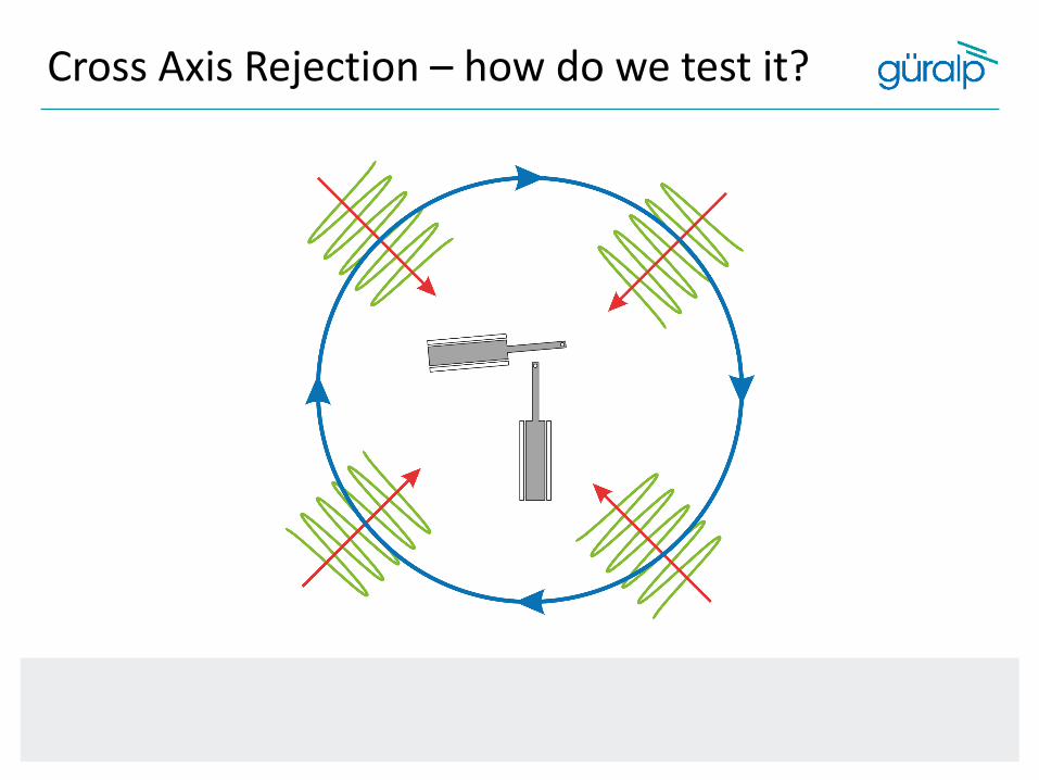
Cross Axis Rejection – how do we test it?

Cross Axis Rejection
Transient Protection
What is vulnerable to transients?

Transient Protection
• Cables• GPS• Digitizer• Boreholes
• If you just have a surface sensor the main vulnerability to transients will be the cable. This is because it acts as an aerial.
What is vulnerable to transients?
Transient Protection
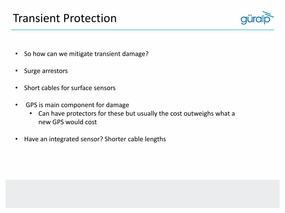
• So how can we mitigate transient damage?
• Surge arrestors
• Short cables for surface sensors
• GPS is main component for damage• Can have protectors for these but usually the cost outweighs what a
new GPS would cost
• Have an integrated sensor? Shorter cable lengths
Output Voltage
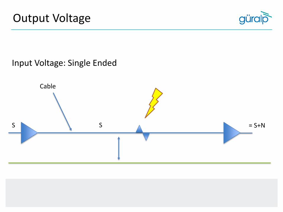
Input Voltage: Single Ended
S = S+NS
Cable

Output Voltage
S
-S
+S = (S+N) - (-S+N)= 2S
Input Voltage: Differential
Cable

To Recap
This morning we have discussed:
Broadband vs Short Period
Dynamic Range
Sensitivity
Sensor Component Orientation (UVW vs XYZ)
Self – Noise
FBA vs MEMS
Transient Protection
Cross Axis Rejection
Output Voltage

STUART ALLARDICECLIENT RELATIONSHIP MANAGER(Americas Region)
Tel: +44 (0) 1189 819056 Ext: 313Cell: +44 (0) 777 569 4200
Email: [email protected]@guralp.com
Skype: stuart_allardice_gsl
Thank You! Any Questions?