
Principle of Light Transmission and Fiber Geometry
44
CETTM MTNL Principle of Light Transmission 1 TOFCPLT024 T818 ITEC - SCAAP Training Programme Mod Id : TOFCPLT024 Principle of Light Transmission
-
Upload
amirsalahibrahim -
Category
Documents
-
view
224 -
download
1
description
Principle of Light Transmission and Fiber Geometry
Transcript of Principle of Light Transmission and Fiber Geometry
CETTM MTNL
Principle of Light Transmission 1TOFCPLT024
T818
ITEC - SCAAP Training Programme
Mod Id : TOFCPLT024
Principle of Light Transmission
CETTM MTNL
Principle of Light Transmission 2TOFCPLT024
Light Propagation through O.F
� Rarer to Denser medium
- Refracted rays move towards the normal
� Denser to Rarer medium
- Refracted rays move away from normal
CETTM MTNL
Principle of Light Transmission 3TOFCPLT024
�Critical angle:- The angle of incidence in the
denser medium for which the angle of
refraction is 90°
�When the angle of incidence is greater than
the critical angle, Total Internal Reflection
occurs.
�Refractive Index of core is 1.48
�Refractive Index of cladding is 1.46
Contd..
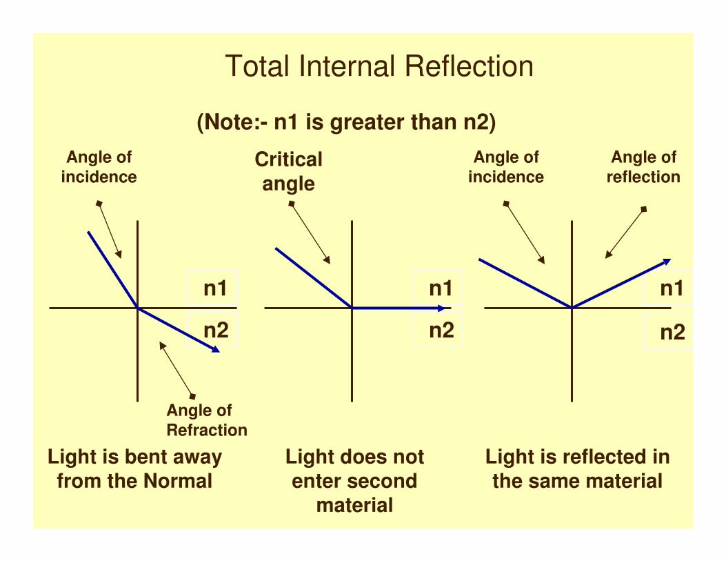
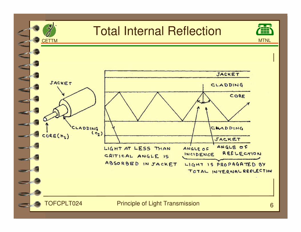
Total Internal Reflection
n1
n2
n1
n2
n1
n2
Angle ofincidence
Angle of
Refraction
Light is bent away
from the Normal
Light does not
enter second
material
Light is reflected in
the same material
Angle ofincidence
Angle ofreflection
Critical
angle
(Note:- n1 is greater than n2)
CETTM MTNL
Principle of Light Transmission 5TOFCPLT024
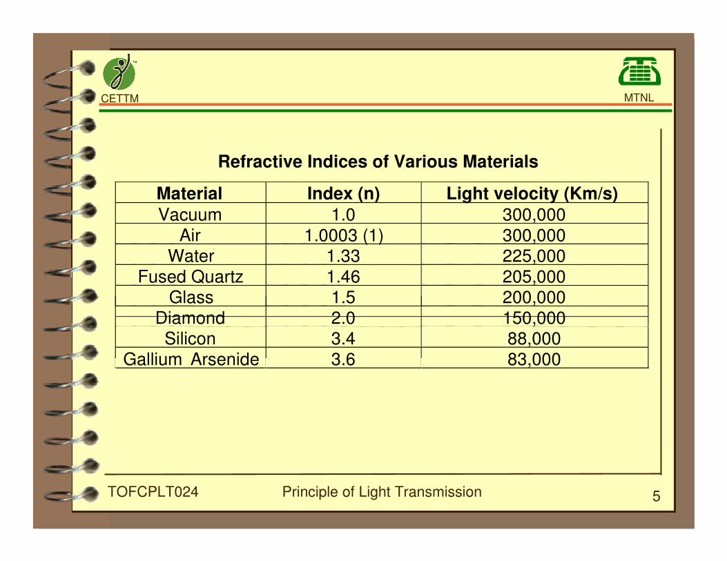
Refractive Indices of Various Materials
Material Index (n) Light velocity (Km/s)
Vacuum 1.0 300,000Air 1.0003 (1) 300,000
Water 1.33 225,000Fused Quartz 1.46 205,000
Glass 1.5 200,000Diamond 2.0 150,000Silicon 3.4 88,000
Gallium Arsenide 3.6 83,000
CETTM MTNL
Principle of Light Transmission 6TOFCPLT024
Total Internal Reflection
CETTM MTNL
Principle of Light Transmission 7TOFCPLT024
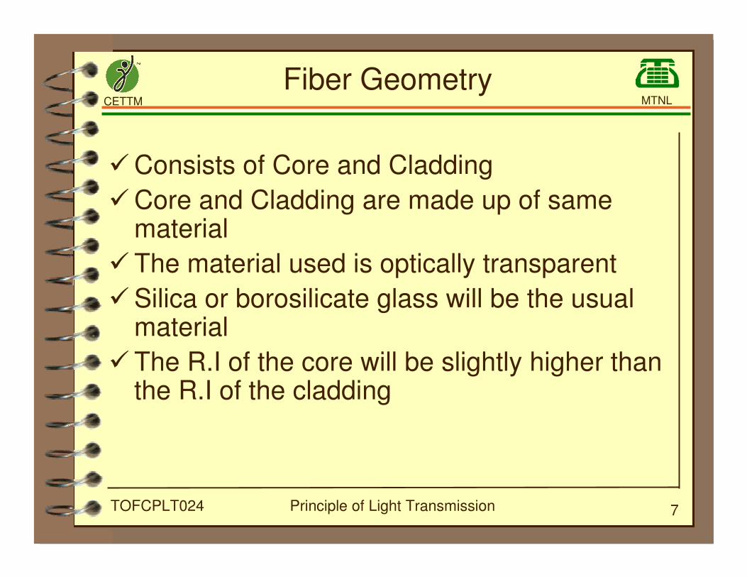
Fiber Geometry
�Consists of Core and Cladding
�Core and Cladding are made up of samematerial
�The material used is optically transparent
�Silica or borosilicate glass will be the usualmaterial
�The R.I of the core will be slightly higher thanthe R.I of the cladding
CETTM MTNL
Principle of Light Transmission 8TOFCPLT024
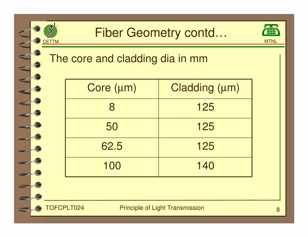
Fiber Geometry contd…
The core and cladding dia in mm
140100
12562.5
12550
1258
Cladding (µm)Core (µm)

CETTM MTNL
Principle of Light Transmission 9TOFCPLT024
Construction of O.F.Cables
�Optical fiber cable needs protection before itis used.
�Cabling means process to package one ormore fibers in an outer protective structure.
�Cabling improves the mechanicalcharacteristics of a fiber without causing adeterioration of its optical properties.
CETTM MTNL
Principle of Light Transmission 10TOFCPLT024
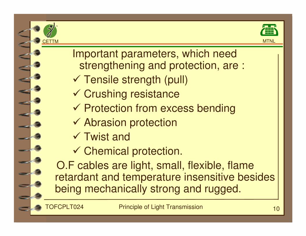
Important parameters, which needstrengthening and protection, are :
� Tensile strength (pull)
� Crushing resistance
� Protection from excess bending
� Abrasion protection
� Twist and
� Chemical protection.
O.F cables are light, small, flexible, flameretardant and temperature insensitive besidesbeing mechanically strong and rugged.
CETTM MTNL
Principle of Light Transmission 11TOFCPLT024
Main Components of Optical Fiber Cable
�OF cable is mainly divided into two parts :
- Metallic
- Non-metallic
�Metallic frame cables are those which usemetallic component for protection and alsomay be metallic conductors. Non metallicfiber cables use non-metallic protectionmaterial.There is no metal componentinvolved in the cable.
CETTM MTNL
Principle of Light Transmission 12TOFCPLT024
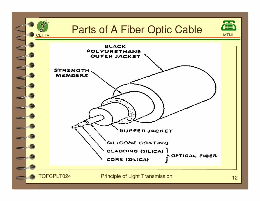
Parts of A Fiber Optic Cable
CETTM MTNL
Principle of Light Transmission 13TOFCPLT024
Optic Fiber Cable
The following components are commonly used inmost of the cables.
� Buffer
� Strength member
� Filler and core wraps
� Jacket and moisture barrier
CETTM MTNL
Principle of Light Transmission 14TOFCPLT024
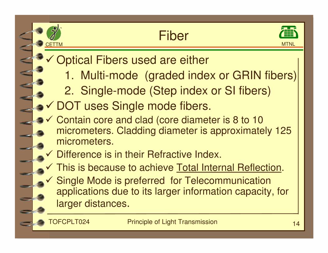
�Optical Fibers used are either
1. Multi-mode (graded index or GRIN fibers)
2. Single-mode (Step index or SI fibers)
�DOT uses Single mode fibers.� Contain core and clad (core diameter is 8 to 10
micrometers. Cladding diameter is approximately 125micrometers.
� Difference is in their Refractive Index.
� This is because to achieve Total Internal Reflection.
� Single Mode is preferred for Telecommunicationapplications due to its larger information capacity, for
larger distances.
Fiber
CETTM MTNL
Principle of Light Transmission 15TOFCPLT024
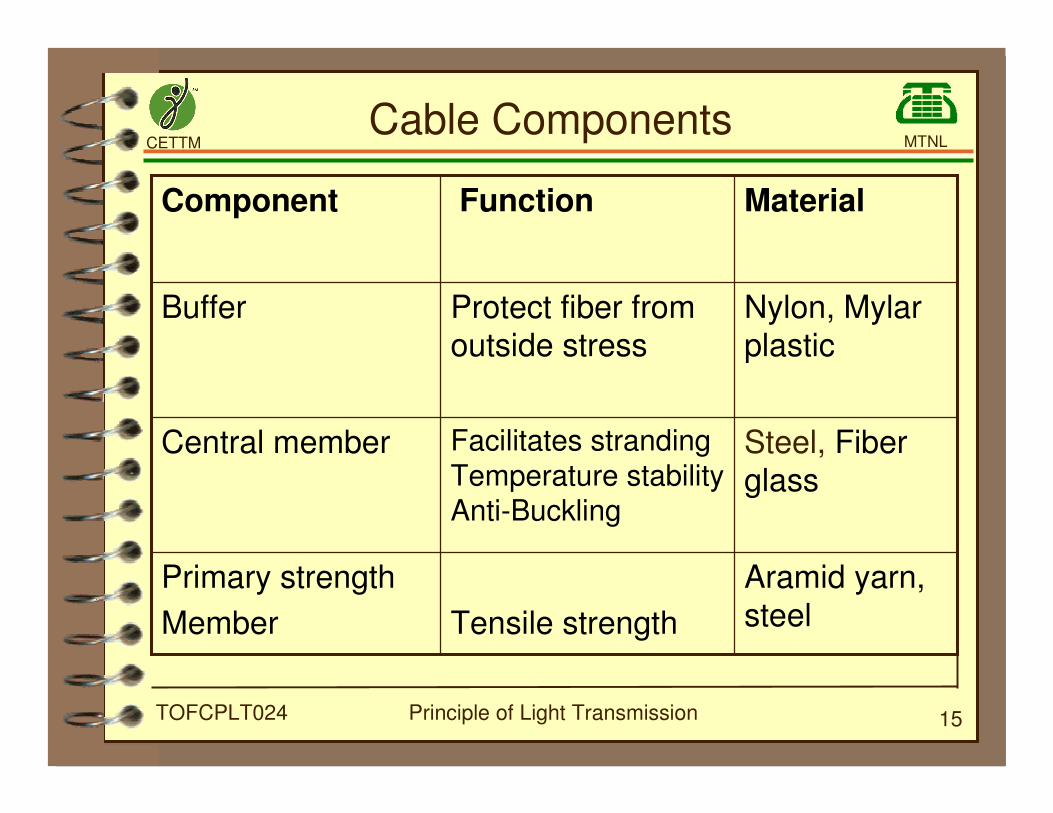
Aramid yarn,
steelTensile strength
Primary strength
Member
Steel, Fiberglass
Facilitates stranding
Temperature stabilityAnti-Buckling
Central member
Nylon, Mylarplastic
Protect fiber fromoutside stress
Buffer
Material FunctionComponent
Cable Components
CETTM MTNL
Principle of Light Transmission 16TOFCPLT024
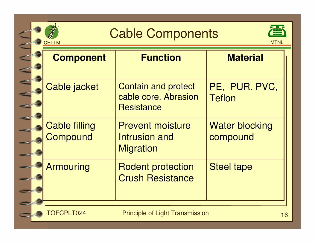
Steel tapeRodent protection
Crush Resistance
Armouring
Water blockingcompound
Prevent moistureIntrusion and
Migration
Cable fillingCompound
PE, PUR. PVC,
Teflon
Contain and protect
cable core. AbrasionResistance
Cable jacket
MaterialFunctionComponent
Cable Components
CETTM MTNL
Principle of Light Transmission 17TOFCPLT024
Buffers
�Fibers are coated with a buffer immediatelyafter being drawn. This buffer known asprimer.
�Primary coating is made of silicon rubber,Acrylate, or lacquer.
�Applied to the cladding by the fibermanufacturer. This coating serves asmechanical protection during the subsequentstages of the cable manufacturing.
�Typical diameter of the fiber after primarycoating is 250-350 micrometer.

CETTM MTNL
Principle of Light Transmission 18TOFCPLT024
Buffers
�After primary coating fibers are normallycoloured by passing through colouringmachines.
�Coloured fibers are passed through theadditional buffers.
�Additional buffers are called Secondarycoating.
1. LOOSE BUFFER
2. TIGHT BUFFER
CETTM MTNL
Principle of Light Transmission 19TOFCPLT024
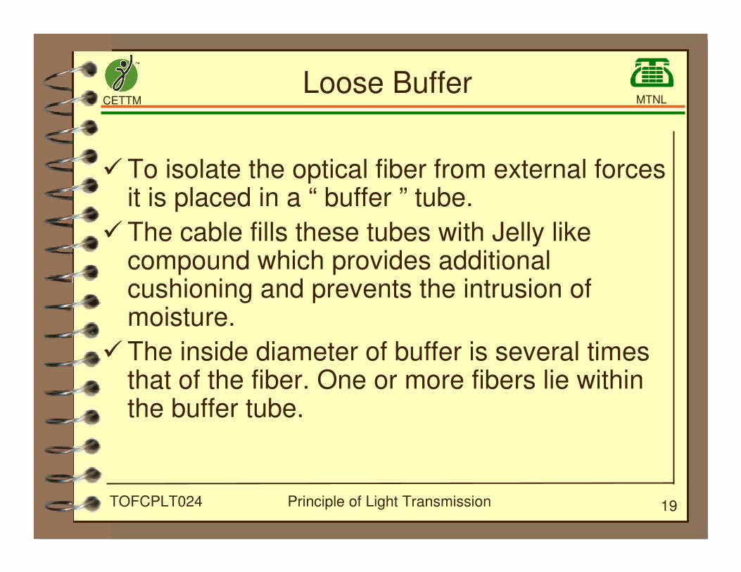
Loose Buffer
�To isolate the optical fiber from external forcesit is placed in a “ buffer ” tube.
�The cable fills these tubes with Jelly likecompound which provides additionalcushioning and prevents the intrusion ofmoisture.
�The inside diameter of buffer is several timesthat of the fiber. One or more fibers lie withinthe buffer tube.
CETTM MTNL
Principle of Light Transmission 20TOFCPLT024
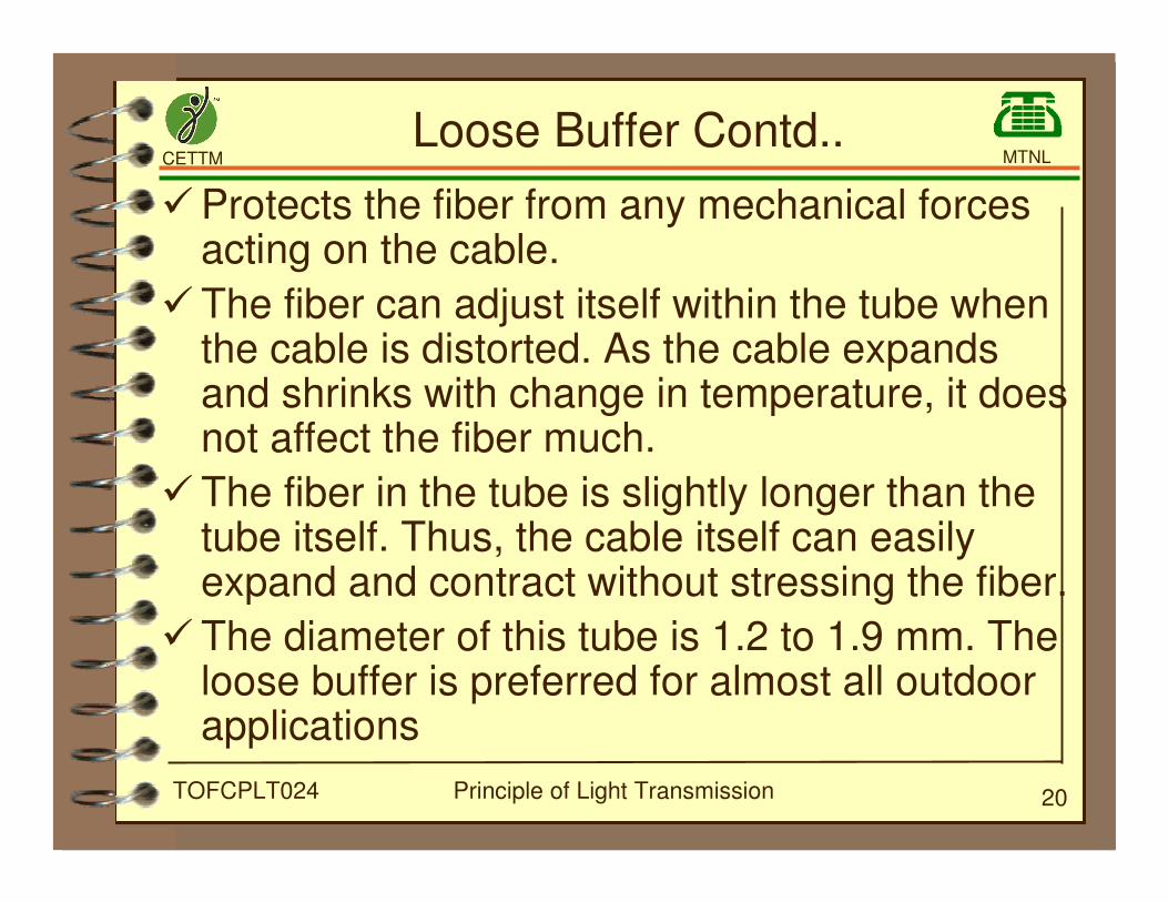
Loose Buffer Contd..
�Protects the fiber from any mechanical forcesacting on the cable.
�The fiber can adjust itself within the tube whenthe cable is distorted. As the cable expandsand shrinks with change in temperature, it doesnot affect the fiber much.
�The fiber in the tube is slightly longer than thetube itself. Thus, the cable itself can easilyexpand and contract without stressing the fiber.
�The diameter of this tube is 1.2 to 1.9 mm. Theloose buffer is preferred for almost all outdoorapplications
CETTM MTNL
Principle of Light Transmission 21TOFCPLT024
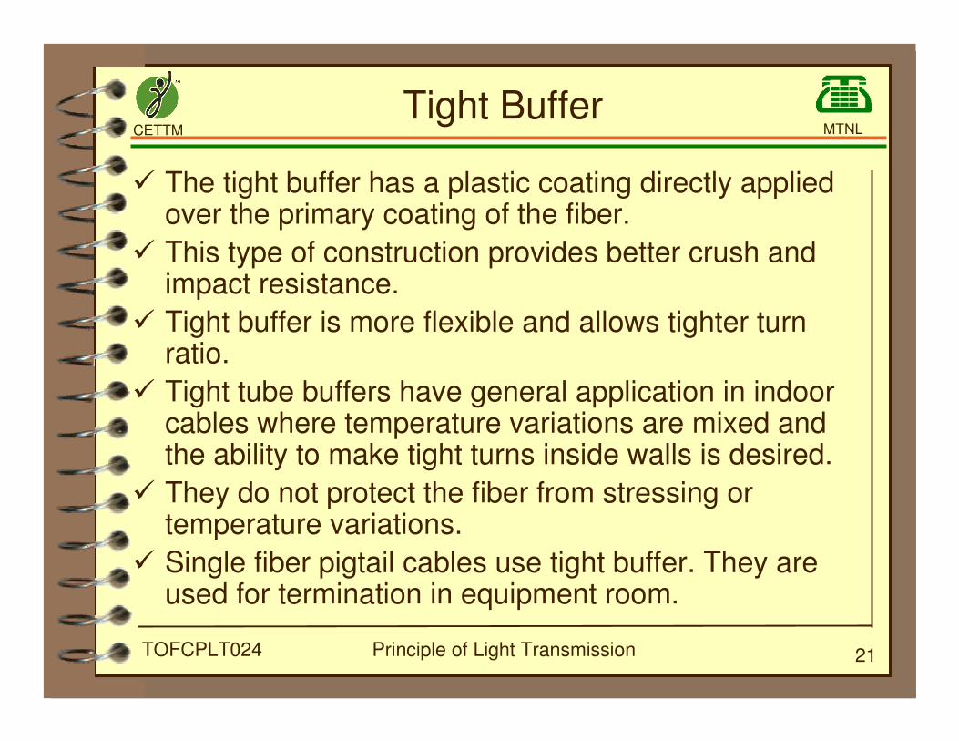
Tight Buffer
� The tight buffer has a plastic coating directly appliedover the primary coating of the fiber.
� This type of construction provides better crush andimpact resistance.
� Tight buffer is more flexible and allows tighter turnratio.
� Tight tube buffers have general application in indoorcables where temperature variations are mixed andthe ability to make tight turns inside walls is desired.
� They do not protect the fiber from stressing ortemperature variations.
� Single fiber pigtail cables use tight buffer. They areused for termination in equipment room.
CETTM MTNL
Principle of Light Transmission 22TOFCPLT024
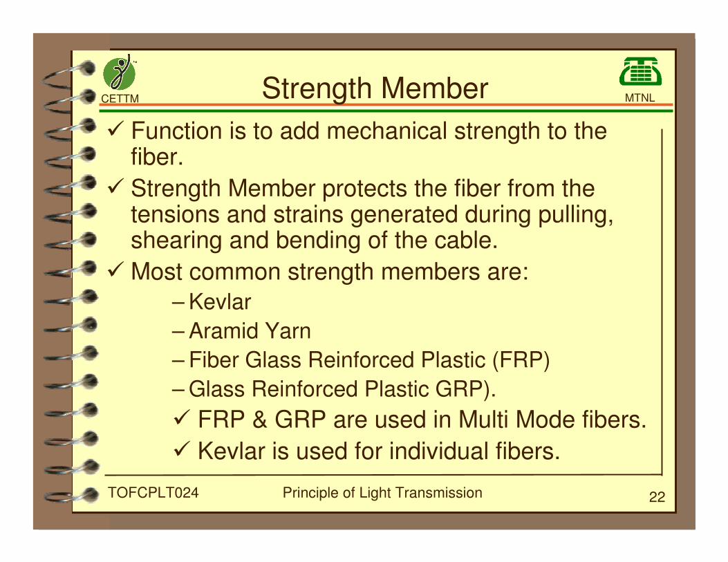
Strength Member
� Function is to add mechanical strength to thefiber.
� Strength Member protects the fiber from thetensions and strains generated during pulling,shearing and bending of the cable.
� Most common strength members are:
– Kevlar
– Aramid Yarn
– Fiber Glass Reinforced Plastic (FRP)
– Glass Reinforced Plastic GRP).
� FRP & GRP are used in Multi Mode fibers.
� Kevlar is used for individual fibers.
CETTM MTNL
Principle of Light Transmission 23TOFCPLT024
Fillers and Core Wraps
� Fillers are employed to provide cushioning to thefibers and to give shape to the cable.
� Typical materials are PVC, Polyethylene, low densitycellulose paper, spun bonded polyester.
� Cable core is generally filled with a water blocking orfilling compound for preventing moisture intrusion.
� Binder tapes are applied to hold the assemblies ofcoated fibers and fillers, together.
� It also provides a heat barrier to the fiber during theextrusion process of outer sheath. Usual materialsare polyester, Mylar, cellulose paper, etc.
CETTM MTNL
Principle of Light Transmission 24TOFCPLT024
Jacket & Moisture Barrier
� The jacket or sheath provides protection from theeffects of cut and abrasion, oil, ozone, acids, alkali,solvents etc.
� Materials such as low density polyethylene, highdensity polythene, poly urethene, polyvinyl chloride(PVC), nylon, etc. have been successfully employedin commercial cables.
� The choice of jacket material depends on applicationand cost.
� In cable containing several layers of jacketing andprotective material, the outer layers are often calledthe SHEATH. The inner layer which directly protectsthe fibers becomes the jacket.
CETTM MTNL
Principle of Light Transmission 25TOFCPLT024
� Types of cables
- Loose tube structure
- Slotted core structure
� Length of the cable drum is 2 Kms.
Optical Fiber Cable Configurations
CETTM MTNL
Principle of Light Transmission 26TOFCPLT024
Loose tube structure� Uses protective loose tube which is made up of
thermo plastic material.
� Tubes are stranded helically in continuous oralternate paths around a central strengthmember.
� Central strength member is FRP or GRP.
� Tubes are filled with materials which have stablephysical characteristics over a wide range oftemperature.
� Cable interstices are filled with moisture resistantfilling compound to retard ingress and axialmigration of water.
� Cable core is wrapped with a wrapping tape.
CETTM MTNL
Principle of Light Transmission 27TOFCPLT024
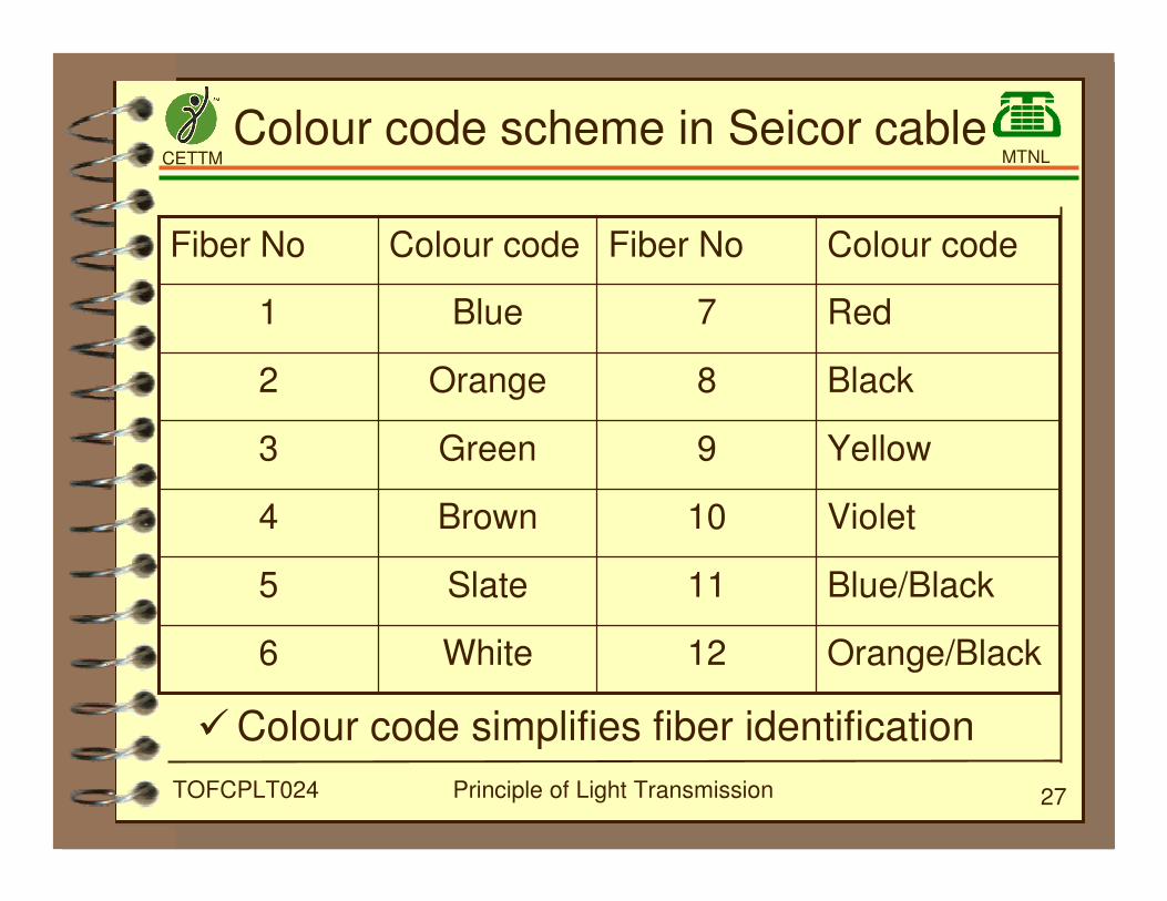
Colour code scheme in Seicor cable
Orange/Black12White6
Blue/Black11Slate5
Violet10Brown4
Yellow9Green3
Black8Orange2
Red7Blue1
Colour codeFiber NoColour codeFiber No
�Colour code simplifies fiber identification
CETTM MTNL
Principle of Light Transmission 28TOFCPLT024
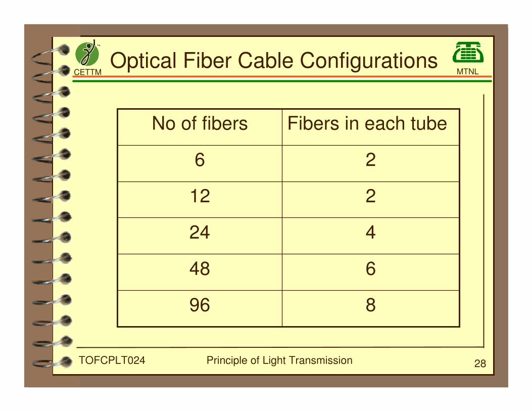
Optical Fiber Cable Configurations
896
648
424
212
26
Fibers in each tubeNo of fibers
CETTM MTNL
Principle of Light Transmission 29TOFCPLT024
Slotted core structure
�Consists of a plastic rod abstracted over a
central strength member assuring good
mechanical and thermal performance of the
structure.
�V-grooves or slots are cut in the surface of the
plastic rod.
�These grooves or slots may contain one or
more fibers protected only by primary coating.
CETTM MTNL
Principle of Light Transmission 30TOFCPLT024
Slotted core structure contd..
�After insertion of the fiber, the slotted core is
closed by applying plastic or synthetic
covering.
�Wherever necessary, slots are filled with a
filling compound having stable physical
characteristics over a wide range of
temperature.
�Each slotted core may be used alone with
protective outer jacket, or assembled with
similar cable units before providing outer
protection.
CETTM MTNL
Principle of Light Transmission 31TOFCPLT024
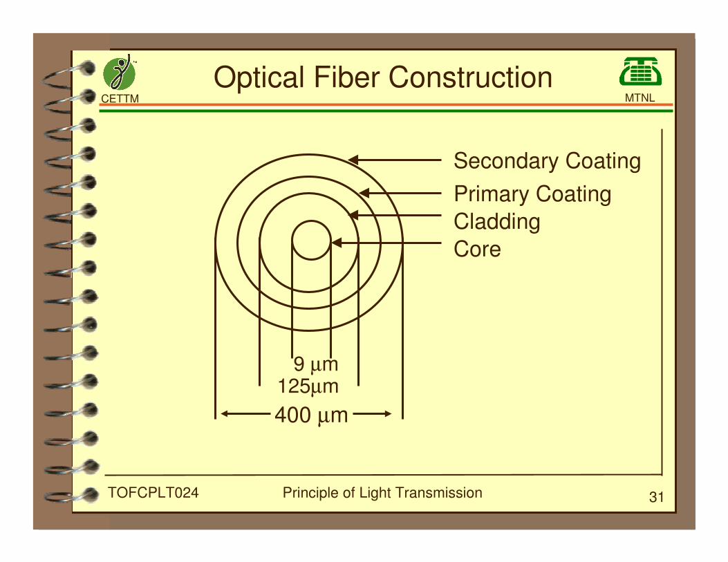
Optical Fiber Construction
9 µm125µm
400 µm
Secondary Coating
Primary Coating
Cladding
Core
CETTM MTNL
Principle of Light Transmission 32TOFCPLT024
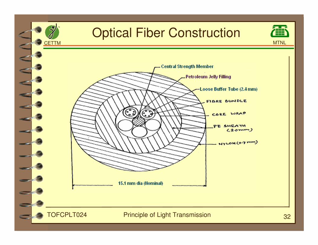
Optical Fiber Construction
CETTM MTNL
Principle of Light Transmission 33TOFCPLT024
�Cabling is packing one or more fibres in a
outer protective cover
�Cabling protects environmentally and
mechanically
O.F Cable Construction
CETTM MTNL
Principle of Light Transmission 34TOFCPLT024
Components of Cable
�Fibers
�Buffers
�Fillers
�Strength Members
�Core wraps
� Jacket/Moisture Barrier
CETTM MTNL
Principle of Light Transmission 35TOFCPLT024
Outer Sheath
�Also known as External Sheath
�Nylon sheath of not less than 0.7 mm thick
�Orange coloured -- used by communication
units
�Green / Black coloured -- used by Railways
CETTM MTNL
Principle of Light Transmission 36TOFCPLT024
Inner Sheath
�Also known as inner jacket
�Black coloured sheath
�Not less than 2.0 mm thick
CETTM MTNL
Principle of Light Transmission 37TOFCPLT024
Central Strengthening Member
�To add mechanical strength to cable so that
pulling tension and tension at bends can be
with stood.
�Solid GRP (Glass Reinforced Plastic) non-
metalic
�Outer dia 2.1±0.15 mm
CETTM MTNL
Principle of Light Transmission 38TOFCPLT024
Slotted Core Structure
�Plastic rod extruded over a strength member
with good mechanical and thermal
performance.
�V- Grooves or slots cut on the surface of rod.
�Each group is containing one/more primary
coated fiber.
CETTM MTNL
Principle of Light Transmission 39TOFCPLT024
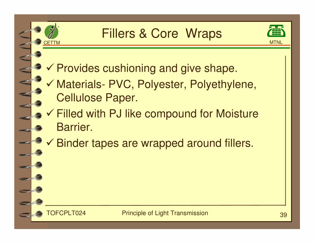
Fillers & Core Wraps
�Provides cushioning and give shape.
�Materials- PVC, Polyester, Polyethylene,
Cellulose Paper.
�Filled with PJ like compound for Moisture
Barrier.
�Binder tapes are wrapped around fillers.
CETTM MTNL
Principle of Light Transmission 40TOFCPLT024
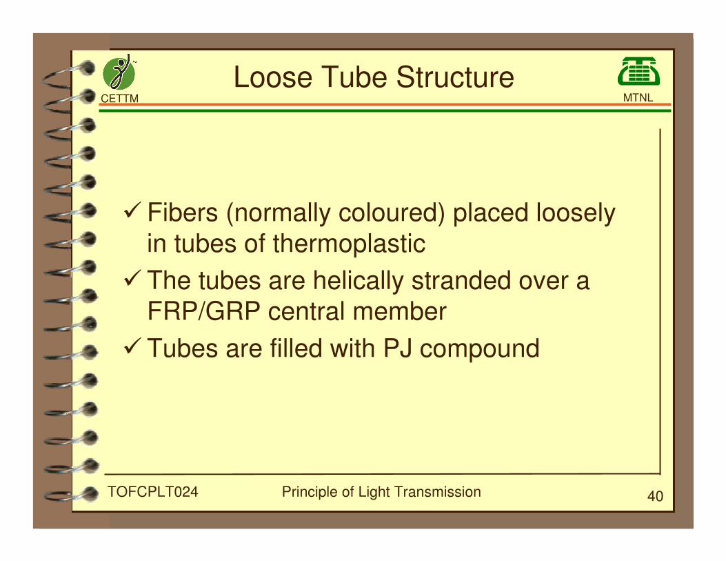
Loose Tube Structure
�Fibers (normally coloured) placed loosely
in tubes of thermoplastic
�The tubes are helically stranded over a
FRP/GRP central member
�Tubes are filled with PJ compound
CETTM MTNL
Principle of Light Transmission 41TOFCPLT024
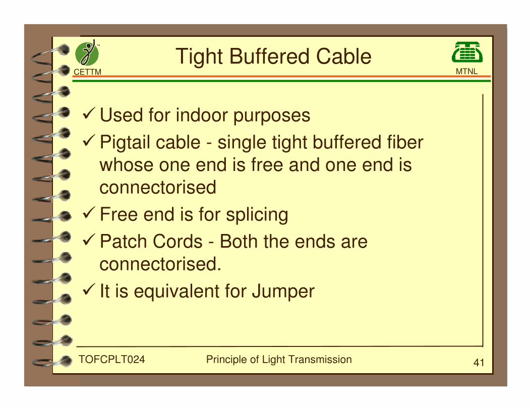
Tight Buffered Cable
�Used for indoor purposes
�Pigtail cable - single tight buffered fiber
whose one end is free and one end is
connectorised
�Free end is for splicing
�Patch Cords - Both the ends are
connectorised.
� It is equivalent for Jumper
CETTM MTNL
Principle of Light Transmission 42TOFCPLT024
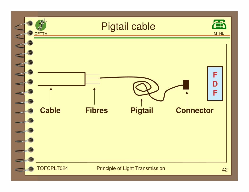
FDF
Cable Fibres Pigtail Connector
Pigtail cable
CETTM MTNL
Principle of Light Transmission 43TOFCPLT024
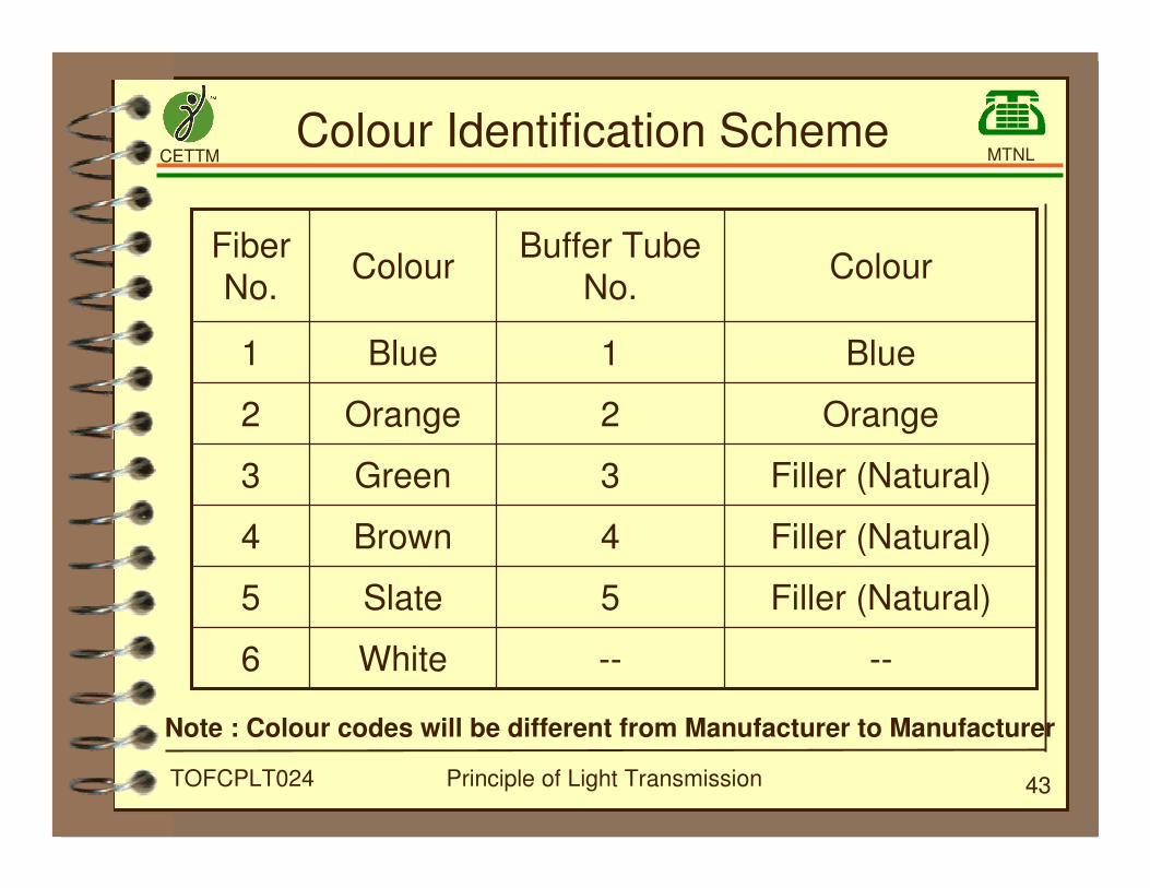
Colour Identification Scheme
----White6
Filler (Natural)5Slate5
Filler (Natural)4Brown4
Filler (Natural)3Green3
Orange2Orange2
Blue1Blue1
ColourBuffer Tube
No.Colour
Fiber
No.
Note : Colour codes will be different from Manufacturer to Manufacturer
CETTM MTNL
Principle of Light Transmission 44TOFCPLT024
Thank You


![Simple Design for Singlemode High Power CW Fiber Laser using Multimode High NA Fiber · 2014. 10. 1. · ytterbium fiber laser was recently demonstrated using such principle[1]. Excellent](https://static.fdocuments.in/doc/165x107/61061977eaa77640985a35b6/simple-design-for-singlemode-high-power-cw-fiber-laser-using-multimode-high-na-fiber.jpg)