Primljen / Received: 27.3.2013. Evaluation of infill strut ...
13
Građevinar 6/2013 509 GRAĐEVINAR 65 (2013) 6, 509-521 UDK 624.072.33.001.5:624.071.3 Autohrs: Sanja Hak, PhD. CE University of Zagreb Faculty of Civil Engineerin [email protected] Paolo Morandi, PhD. CE University of Pavia Department of Civil Engineering and Architecture EUCENTRE, Pavia, Italy [email protected] Prof. Guido Magenes, PhD. CE University of Pavia Department of Civil Engineering and Architecture EUCENTRE, Pavia, Italy [email protected] Original scientific paper Sanja Hak, Paolo Morandi, Guido Magenes Evaluation of infill strut properties based on in-plane cyclic tests In the nonlinear analysis of masonry infilled RC frame structures, simple strut models are often adopted to represent the masonry infill, particularly in the case of extensive parametric numerical studies. Therefore, a careful definition of the corresponding strut properties is of exceptional significance for achieving a realistic building response. A method for evaluation of masonry infill strut properties is proposed and applied in this paper, based on the interpretation of results obtained by cyclic in-plane testing of single-storey, single-bay bare and infilled RC frame specimens. Key words: masonry infill, equivalent diagonal strut, cyclic in-plane testing, limit states Izvorni znanstveni rad Sanja Hak, Paolo Morandi, Guido Magenes Određivanje svojstava tlačnog štapa ispune temeljem cikličkih ispitivanja u ravnini U nelinearnoj analizi AB okvira sa zidanom ispunom jednostavni se zamjenjujući tlačni štap često primjenjuje za modeliranje ispune, posebice u slučaju opsežnih numeričkih proračuna. Stoga je pažljiv odabir odgovarajućih svojstava tlačnog štapa od iznimne važnosti za vjerodostojni prikaz odziva zgrade. U ovom je radu predložen i primijenjen postupak određivanja svojstava tlačnog štapa za prikaz zidane ispune temeljem interpretacije rezultata cikličkih, statičkih ispitivanja u ravnini na uzorcima jednoetažnih, jednorasponskih armiranobetonskih okvira s ispunom i bez nje. Ključne riječi: zidana ispuna, zamjenjujući dijagonalni tlačni štap, cikličko ispitivanje u ravnini, granična stanja Wissenschaftlicher Originalbeitrag Sanja Hak, Paolo Morandi, Guido Magenes Ermittlung der Eigenschaften von Druckstreben für Ausfachungen durch zyklische Versuche in der Ebene In nichtlinearen Berechnungen von Stahlbetonrahmen mit Ausfachungen aus Mauerwerk werden für die Darstellung der Ausfachungen oft Ersatzstabmodelle angewandt, insbesondere wenn umfangreiche numerische Analysen vorgesehen sind. Um eine realistische Beschreibung des Gebäudeverhaltens zu erzielen, ist die sorgfältige Auswahl entsprechender Eigenschaften der Druckstrebe von entscheidender Bedeutung. In dieser Arbeit ist ein Verfahren für die Charakterisierung des Ersatzstabes für die Darstellung von Ausfachungen mittels der Interpretation von Resultaten zyklischer, statischer Versuche an Proben einfacher einstöckiger Rahmen in der Eben vorgeschlagen und angewandt. Schlüsselwörter: Ausfachung aus Mauerwerk, diagonaler Ersatzstab, zyklische Versuche in der Ebene, Grenzzustände Evaluation of infill strut properties based on in-plane cyclic tests Primljen / Received: 27.3.2013. Ispravljen / Corrected: 12.6.2013. Prihvaćen / Accepted: 17.6.2013. Dostupno online / Available online: 10.7.2013.
Transcript of Primljen / Received: 27.3.2013. Evaluation of infill strut ...
Građevinar 6/2013
509GRAĐEVINAR 65 (2013) 6, 509-521
UDK 624.072.33.001.5:624.071.3
Autohrs:
Sanja Hak, PhD. CEUniversity of ZagrebFaculty of Civil [email protected]
Paolo Morandi, PhD. CEUniversity of PaviaDepartment of Civil Engineering and ArchitectureEUCENTRE, Pavia, [email protected]
Prof. Guido Magenes, PhD. CE University of PaviaDepartment of Civil Engineering and ArchitectureEUCENTRE, Pavia, [email protected]
Original scientific paper
Sanja Hak, Paolo Morandi, Guido Magenes
Evaluation of infill strut properties based on in-plane cyclic tests
In the nonlinear analysis of masonry infilled RC frame structures, simple strut models are often adopted to represent the masonry infill, particularly in the case of extensive parametric numerical studies. Therefore, a careful definition of the corresponding strut properties is of exceptional significance for achieving a realistic building response. A method for evaluation of masonry infill strut properties is proposed and applied in this paper, based on the interpretation of results obtained by cyclic in-plane testing of single-storey, single-bay bare and infilled RC frame specimens.
Key words:masonry infill, equivalent diagonal strut, cyclic in-plane testing, limit states
Izvorni znanstveni radSanja Hak, Paolo Morandi, Guido Magenes
Određivanje svojstava tlačnog štapa ispune temeljem cikličkih ispitivanja u ravnini
U nelinearnoj analizi AB okvira sa zidanom ispunom jednostavni se zamjenjujući tlačni štap često primjenjuje za modeliranje ispune, posebice u slučaju opsežnih numeričkih proračuna. Stoga je pažljiv odabir odgovarajućih svojstava tlačnog štapa od iznimne važnosti za vjerodostojni prikaz odziva zgrade. U ovom je radu predložen i primijenjen postupak određivanja svojstava tlačnog štapa za prikaz zidane ispune temeljem interpretacije rezultata cikličkih, statičkih ispitivanja u ravnini na uzorcima jednoetažnih, jednorasponskih armiranobetonskih okvira s ispunom i bez nje.
Ključne riječi:zidana ispuna, zamjenjujući dijagonalni tlačni štap, cikličko ispitivanje u ravnini, granična stanja
Wissenschaftlicher OriginalbeitragSanja Hak, Paolo Morandi, Guido Magenes
Ermittlung der Eigenschaften von Druckstreben für Ausfachungen durch zyklische Versuche in der Ebene
In nichtlinearen Berechnungen von Stahlbetonrahmen mit Ausfachungen aus Mauerwerk werden für die Darstellung der Ausfachungen oft Ersatzstabmodelle angewandt, insbesondere wenn umfangreiche numerische Analysen vorgesehen sind. Um eine realistische Beschreibung des Gebäudeverhaltens zu erzielen, ist die sorgfältige Auswahl entsprechender Eigenschaften der Druckstrebe von entscheidender Bedeutung. In dieser Arbeit ist ein Verfahren für die Charakterisierung des Ersatzstabes für die Darstellung von Ausfachungen mittels der Interpretation von Resultaten zyklischer, statischer Versuche an Proben einfacher einstöckiger Rahmen in der Eben vorgeschlagen und angewandt.
Schlüsselwörter:Ausfachung aus Mauerwerk, diagonaler Ersatzstab, zyklische Versuche in der Ebene, Grenzzustände
Evaluation of infill strut properties based on in-plane cyclic tests
Primljen / Received: 27.3.2013.
Ispravljen / Corrected: 12.6.2013.
Prihvaćen / Accepted: 17.6.2013.
Dostupno online / Available online: 10.7.2013.
Građevinar 6/2013
510 GRAĐEVINAR 65 (2013) 6, 509-521
Sanja Hak, Paolo Morandi, Guido Magenes
1. Introduction
Even though numerous finite element models of different refinement levels are available for the representation of non-structural masonry infills, such as those presented in [1, 2], simple pin-ended single-strut elements for nonlinear numerical modelling of masonry infilled RC structures are widely adopted. Such a simplified approach, frequently used in extensive parametric seismic response analyses, is particularly appropriate in cases when evaluation of the global structural displacement demand is of primary interest. However, possible influence of infill on load-bearing structural elements due to local effects cannot be directly captured with such a simplified model [3], which is why only the in-plane infill response can be accounted for. Based on field experience from previous earthquake events, numerous examples of combined in-plane and out-of-plane masonry infill damage have been reported, e.g. [4, 5], which points to a strong correlation between possible out-of-plane collapse and previous in-plane damage that should be accounted for in resistance verifications [6]. In the case of masonry infills built in full contact with the surrounding frame, the out-of-plane resistance of undamaged masonry infill panels, depending on the slenderness ratio, has shown to be relatively high, e.g. [8], which is due to activation of an arching action mechanism [7]. Hence, the contribution of the non-structural infill to the structural response due to in-plane horizontal actions, and an appropriate estimation of the actual infill response, are considered to be of primary importance in this work. Consequently, in order to establish a simple masonry infill model, a particular attention has to be devoted to the definition of the corresponding equivalent diagonal strut properties. This fact becomes additionally important when the principal attention is not focused on the frame response only, but also on the evaluation of the masonry infill behaviour and the corresponding distribution of in-plane damage. A masonry infill strut model is commonly defined by an axial stress-strain relationship in the case of monotonic loading, and by the corresponding hysteretic rule in the case of cyclic loading, as well as by the strength and stiffness properties, which are closely related to the evaluation of the equivalent strut width, e.g. [9]. The deformation capacity of the infill, being of particular importance for infill damage assessment, is mainly reflected in the stress-strain relationship, which therefore has to be defined with caution. A procedure for the evaluation of parameters required to define a simple single strut masonry infill model is proposed in this paper, based on the comparison of experimental and numerical results describing the behaviour of infilled and bare frame configurations, while the primary attention is paid to the evaluation
of strain values characterising nonlinear behaviour of the strut. Performance criteria for a single masonry infill can be defined based on the infill properties to be obtained, supported by the evidence of experimentally achieved damage. Therefore, in order to permit simple implementation of available test data in numerical applications, and to allow a consistent comparison of infill properties in terms of strength, stiffness and deformation capacity for different masonry typologies (e.g. made of perforated clay bricks, as commonly used in several European countries), a method for interpretation of experimental results obtained from in-plane cyclic quasi-static tests on infilled single-storey, single-bay RC frames has been adopted [10]. Using the proposed approach, numerical models representing three different masonry infill typologies have been calibrated, starting from the existing test results evaluated in a previous experimental campaign conducted at the University of Pavia in Italy [11, 12].
2. Masonry Infill Model Parameters
2.1. Modelling approach
A nonlinear structural model based on the concentrated plasticity approach is assumed to define the RC structural elements, in order to evaluate properties of the equivalent diagonal masonry infill strut. Each member is represented by a one-component model [13] consisting of a frame element, assumed to remain perfectly elastic, with nonlinear hinges at the ends, characterized by a modified Takeda hysteresic response [14]. The initial to post-yielding stiffness ratio is defined by the Ramberg-Osgood [15] moment-curvature bi-linear factor. No strength degradation is taken into account, and the possibility of shear failure in structural elements is not considered, supposing adequate design and detailing according to modern seismic design provisions.Various constitutive models are available for definition of the axial stress-strain relationship, assigned to the equivalent masonry strut. Examples can be found in early findings by Klingner and Bertero [16] (Figure 1a), or in the further developments by Crisafulli [17] (Figure 1b) and, more recently, by Rodrigues et al. [18] (Figure 1c). A general simplification of strut behaviour for nonlinear static analyses is suggested by Fardis [19] (Figure 1d). In this study, the axial strain-stress relationship proposed by Crisafulli [17] (Figure 1b), has been used to model capacity of the equivalent strut. A similar procedure may be used in the case of different modelling assumptions related to the representation of structural elements and other choices regarding the infill model. Even though investigations conducted in this study are principally based on nonlinear static analyses, the corresponding

Građevinar 6/2013
511GRAĐEVINAR 65 (2013) 6, 509-521
Evaluation of infill strut properties based on in-plane cyclic tests
Crisafulli cyclic hysteretic rule [17] is illustrated in Figure 2a for the sake of completeness. In the scope of this work, stiffness properties of the equivalent masonry strut are determined by evaluating the bw/dw ratio, where bw is the equivalent strut width and dw is the diagonal length of the infill (Figure 2b), based on the proposal by Decanini et al. [20], while the thickness of the strut tw has been assumed equal to infill thickness. The elastic modulus of masonry Ewθ assigned to the inclined direction of the strut is evaluated based on a common model for orthotropic elastic materials subjected to bi-axial stresses.
2.2. Performance levels
Independently of the infill model that is being implemented, two important parameters can be associated to the extent of masonry damage, i.e., the axial strain (or displacement) corresponding to the maximum axial stress (or force), with reference to the onset of slight damage, and the ultimate strain (or displacement), related to the achievement of severe damage. Consequently, the most important parameters required to define the stress-strain relationship that need to be evaluated are the strain εm’ corresponding to the peak axial stress fm’, as well as the ultimate strain εu. In particular, when the calibrated model is to be used for numerical analyses in which the assessment of damage achieved in non-structural masonry elements is of primary interest, the strain parameters are of major importance, since they can be directly related to the masonry infill deformation capacity.
The definition of limit state conditions currently present in European seismic design provisions for new buildings [21] does not comprehensively refer to design situations related to infill damage, and no specific criteria are provided for the quantification of acceptable levels of damage. The general damage limitation requirements are considered satisfied if in each storey of the building the inter-storey drifts induced by the damage limitation seismic action do not exceed the inter-storey drift limits, defined for buildings with brittle non-structural elements attached to the structure, with ductile non-structural elements and with non-structural elements fixed in such a way that they do not interfere with structural deformations, or without non-structural elements, equal to 0.50 %, 0.75 % and 1.00 %, respectively. As regards the design of new buildings, similar requirements can also be found in other codes, such as the International Building Code (2012 IBC [22]), referring to ASCE/SEI 7-10 [23] for seismic design situations, the National Building Code of Canada (2010 NBCC [24]), and the New Zealand Standard (NZS 1170.5:2004 [25]), implying verifications at different limit states. Aimed at assessing performance of existing structures, guidance documents issued by the Federal Emergency Management Agency (FEMA 306 [26], FEMA 307 [27]) provide some recommendations related to the definition of limit states with reference to the deformation capacity of different types of infill. Furthermore, a considerable number of previous experimental studies, e.g. [8, 17, 28, 29], have resulted in important general conclusions and implications related to the propagation of infill damage at increasing levels of in-plane drift.
Figure 1. Stress-strain envelopes after: a) Klingner & Bertero [16]; b) Crisafulli [17]; c) Rodrigues et al. [18]; d) Fardis [19]
Figure 2. a) Crisafulli hysteretic rule [17]; b) Equivalent diagonal single-strut model; c) Performance levels for a single masonry infill
Građevinar 6/2013
512 GRAĐEVINAR 65 (2013) 6, 509-521
Sanja Hak, Paolo Morandi, Guido Magenes
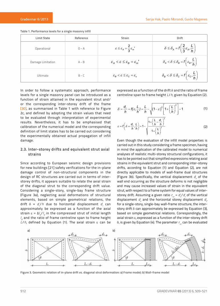
In order to follow a systematic approach, performance levels for a single masonry panel can be introduced as a function of strain attained in the equivalent strut and/or the corresponding inter-storey drift of the frame [30], as summarised in Table 1 with reference to Figure 2c, and defined by adopting the strain values that need to be evaluated through interpretation of experimental results. Nevertheless, it has to be emphasised that calibration of the numerical model and the corresponding definition of limit states has to be carried out considering the experimentally obtained actual propagation of infill damage.
2.3. Inter-storey drifts and equivalent strut axial strains
Since according to European seismic design provisions for new buildings [21] safety verifications for the in-plane damage control of non-structural components in the design of RC structures are carried out in terms of inter-storey drifts, it appears suitable to relate the axial strain of the diagonal strut to the corresponding drift value. Considering a single-story, single-bay frame structure (Figure 3a), neglecting axial deformations of structural elements, based on simple geometrical relations, the drift δ = dr/h due to horizontal displacement dr can approximately be expressed as a function of the axial strain ε = Δld/ld in the compressed strut of initial length ld and the ratio of frame centreline span to frame height L/h, defined by Equation (1). The axial strain ε can be
expressed as a function of the drift δ and the ratio of frame centreline span to frame height L/h, given by Equation (2).
δ ε ε= = = − −( ) +
−
dh
f( Lh) Lh
Lh
r , 1 1 122
(1)
ε δ= =
= −
+ −
+
f dhLh
Lh
dh
Lh
r
r
, 11
1
2
2 (2)
Even though the evaluation of the infill model properties is carried out in this study considering a frame specimen, having in mind the application of the calibrated model to numerical analyses of realistic multi-storey structural configurations, it has to be pointed out that simplified expressions relating axial strains in the equivalent strut and corresponding inter-storey drifts, according to Equation (1) and Equation (2), are not directly applicable to models of wall-frame dual structures (Figure 3b). Specifically, the vertical displacement dv of the wall end occurring as the structure deforms is not negligible and may cause increased values of strain in the equivalent strut, with respect to a frame system for equal values of inter-storey drift. Assuming a given ratio rv,r = dv/dr of the vertical displacement dv and the horizontal storey displacement dr, for a single-story, single-bay wall-frame structure, the inter-story drift δ can approximately be expressed by Equation (3), based on simple geometrical relations. Correspondingly, the axial strain ε, expressed as a function of the inter-storey drift δ, is given by Equation (4). The parameter rv,r can be evaluated
Limit State Reference Strain Drift
Operational O - A ε ε ε≤ =A m'23
δ δ ε≤ =
A Af ,L
h23
Damage Limitation A - B ε ε ε εA B m'< ≤ = δ δ δ εA B Bf ,Lh
< ≤ =
Ultimate B - C ε ε ε εB C u< ≤ = δ δ δ εB C Cf ,Lh
< ≤ =
Table 1. Performance levels for a single masonry infill
Figure 3. Geometric relation of in-plane drift vs. diagonal strut deformation: a) Frame model; b) Wall-frame model
Građevinar 6/2013
513GRAĐEVINAR 65 (2013) 6, 509-521
Evaluation of infill strut properties based on in-plane cyclic tests
in a simplified manner depending on the ratios of elastic flexural stiffness properties for column and wall to beam elements (EIc/EIb, EIw/EIb), and geometric properties of the system (L1/L, h/L).
δ ε ε= = =+
+ − +( ) −( ) +
dh
f( Lhr )
rLh
r r Lh
rv,r
v,rd v,r, , 1
11 1 12
2 222 2
1
− −
r Lhv,r (3)
ε δ= =
= −
+
+
+f dhLhr
Lh
Lh
rv,r, , 1 1
11 12
2 LLh
dh
r dhr d
hr
dr
v,rr−
+ −
2
2 (4)
When applying the strut model to general building configurations, the difference in the relation between strains and drifts for the wall-frame dual system with respect to the frame may be significant when the achieved damage in the masonry infills is assessed analytically based on strain values in the equivalent strut, and related to corresponding inter-storey drifts of the structure. Based on comparison of expressions given in Equation (1) and Equation (4), it can be observed that higher values of strain are obtained in the dual system than in the frame, for the same inter-storey drift. Clearly, such conclusion is derived theoretically based on the simple equivalent strut model. However, no experimental evidence has been reported in previous studies regarding the performance of masonry infills in contact with RC shear walls.
3. Infill model calibration
3.1. Interpretation of cyclic in-plane test results
The experimental evaluation of the in-plane structural response caused by horizontal excitations for masonry structures is commonly carried out quasi-statically or dynamically, under a given constant axial load. Even though dynamic tests allow a more realistic representation of the seismic action, quasi-static tests tend to show more extensive damage and lower values of strength, in part due to the tendency of masonry to exhibit rate dependent behaviour. Hence, quasi-static testing is in general considered a conservative approach to the study of seismically induced damage to masonry elements [31]. Also for the evaluation of seismic response of masonry infilled RC frames, the application of a cyclic quasi-static test procedure, frequently adopted in experimental studies, e.g. [17, 28, 32], [33], is considered appropriate, especially when the response of masonry infill is of primary interest. For cyclic quasi-static in-plane experiments on single-storey, single-bay masonry infilled RC frame specimens, the loading is commonly introduced by means of a displacement-controlled loading history, during which nd levels of increasing top horizontal displacement (or drift) are imposed, and nc reverse cycles (commonly nc = 3) are performed for each target displacement. Experimental results describing the response of the test specimen to the induced loading are usually displayed
in terms of force-displacement curves for the entire displacement history, i.e., for all loading cycles and all intensity levels. Due to initial degradation of the specimen, the response at different loading cycles of a given target displacement may differ, in particular at higher levels of imposed displacement, and it commonly stabilises around the third cycle. Hence, the interpretation of test results based on overall maximum response envelopes may be misleading in some cases. Moreover, when the structural response obtained from experimental investigations results in non-symmetric force-displacement curves, or when a significant strength degradation occurs during reverse cyclic loading, the determination of adequate capacity curves for numerical applications appears to be additionally ambiguous.To overcome, within given limitations, the discrepancy between the outcome of quasi-static cyclic tests and the need for simplicity in numerical applications, a simplified interpretation of experimental results based on the evaluation of one averaged force-displacement curve obtained from force-displacement curves determined for each loading cycle separately has been introduced [10]. In the case of masonry infilled RC frames, especially for calibration of the masonry infill model, the overall average capacity curve has to be determined for both bare and infilled frames from available experimental data, summarised as follows and illustrated in Figure 4. - The experimentally obtained force-displacement response
of the specimen should be displayed separately for each reverse cycle i = 1...nc, for j = 1...nd displacement levels, in positive and negative direction.
- One force-displacement curve Fi (dj), i = 1...nc, should be found for each cycle enveloping the response for j = 1...nd displacements levels.
- One average force-displacement curve F (dj) should be found from nc envelope curves for each cycle, such that the force amplitude, at displacement dj, corresponds to the average of the force amplitudes from the envelopes for each cycle Fi (dj), i = 1...nc, at the same displacement dj, see Equation (5).
F( F (dn
djc
i ji
nc) )=
=∑11
(5)
Note that average values of force F (dj) have to be determined at displacements dj, available in all envelope curves related to single cycles Fi (dj), i = 1...nc.
- One final average force displacement curve Fm (dj) should be established as the average of the positive F+(dj) and negative F-(dj) branches of the average force displacement curve F (dj), such that the force amplitude, at any displacement dj, corresponds to the corresponding average of absolute values, at the same displacement dj; see Equation (6).
F Fm j j jd d abs d( ) ( ) F ( )= + { }+ −12
(6)

Građevinar 6/2013
514 GRAĐEVINAR 65 (2013) 6, 509-521
Sanja Hak, Paolo Morandi, Guido Magenes
An estimation of the corresponding average contribution of the masonry infill Fw,hor,exp at the corresponding displacement dm,exp’ with respect to the overall average capacity Fmax,exp at the displacement dmax,exp can be determined by subtracting the average force displacement curve of the bare frame from that of the infilled frame, as illustrated in Figure 5. This represents the starting point for the definition of strength and deformation properties of the equivalent diagonal strut through calibration of frame specimens by means of numerical models. Note that the maximum strength reached by the infilled frame Fmax,exp corresponds to the displacement dmax,exp, while the experimentally obtained peak horizontal masonry infill strength Fw,hor,exp is achieved at the displacement dm,exp’ that is commonly lower than dmax,exp. Full degradation, i.e., zero strength, of the masonry infill is assumed to be reached at the displacement denoted by du,exp. The approach adopted for the interpretation of experimental results largely relies on the assumption that the reverse response of the masonry infill is approximately symmetric, as e.g. in the case of predominant diagonal cracking failure, and the onset of degradation does not influence the performance in the opposite direction considerably. In a more general case, depending on the infill failure mode, a more pronounced asymmetric behaviour may occur, especially in the case of sliding shear failure, causing significant coupling in the performance for the two reverse directions. Asymmetric response may be generated also in the case of openings which are not symmetrically positioned within the wall. Such effects may not be
captured in an appropriate manner through the given simplified interpretation of experimental results adopted in this study for the evaluation of the strut properties for a simple single-strut model, and further refinements of the numerical model may be required in order to achieve a satisfactory response.
Figure 5. a) Average capacity curve for bare frame and infilled frame; b) Average masonry infill contribution
Figure 4. Interpretation of typical quasi-static cyclic in-plane test results: a) Bare frame; b) Infilled frame
Građevinar 6/2013
515GRAĐEVINAR 65 (2013) 6, 509-521
Evaluation of infill strut properties based on in-plane cyclic tests
3.2. Comparison of numerical and experimental results
As the first approximation of the stress-strain relationship for the infill model to be defined, founded on results from experimental tests on a single-storey, single-bay infilled frame and the corresponding bare structure, the strain at maximum stress εm,exp’ and the ultimate strain εu,exp can be assumed, according to Equation (2), as being equal to strain values related to the experimentally obtained displacement dm,exp’, at which the average maximum horizontal force in the masonry infill Fw,hor,exp is achieved (Equation (7a)), and the displacement du,exp upon which the masonry infill contribution vanishes (Equation (7b)). Moreover, the peak axial stress fm,exp’ of the diagonal strut, corresponding to Fw,hor,exp may be estimated from Equation (8), where tw represents the infill thickness, bw the equivalent strut width and θ the inclination of the strut.
(7a)εm
m,
'
Lh
d 'h
Lh
,exp
exp
= −+ −
+
11
1
2
2 ,
εu,
Lh
dh
Lh
exp = −+ −
+
11
1
2
2
u,exp
(7b)
f 'Ft b
w,hor,
w wm,exp
exp=cosθ
(8)
Following these initial assumptions, a numerical model of both frame specimens, infilled and bare, can be established. In an ideal case, when the adopted infill model (i.e., within the scope of this work the model proposed by Crisafulli [17]) can be calibrated to fit exactly the experimentally obtained average infill response, the numerically obtained force-displacement curve, evaluated based on a nonlinear static pushover analysis of the infilled frame, should coincide with the previously determined average experimental response, provided a good agreement of the results has been achieved for the bare frame model. In practice, some further adjustments of infill properties may be required based on comparison of numerical and experimental results in order to optimise the model. The given approach can directly be applied for calibration of models used to carry out nonlinear static analyses, since the capacity of the masonry infill can be defined according to the obtained values of strain and stress. Also in the case of cyclic response, when a cyclic hysteretic rule (such as the model proposed by Crisafulli [17], Figure 2a) is adopted, the proposed approach can be applied for the evaluation of strain properties assigned to the corresponding envelope curve. The values of strain at maximum stress εm’ and ultimate strain εu are not significantly influenced by repeated cyclic loading. Hence, the given definition of performance levels in function of achieved inter-storey drifts can be considered applicable for cyclic analyses, as presented
in extensive numerical investigations of multi-storey, multi-bay masonry infilled RC structures [34, 35], based on nonlinear dynamic analyses.
4. Application to different masonry infill typologies
4.1. Interpretation of existing in-plane test results
The proposed infill model calibration has been applied to three different types of masonry infill, based on existing experimental test results from a previous experimental study completed at the University of Pavia in Italy, related to the behaviour of unreinforced and lightly reinforced clay brick masonry infill typologies in newly designed RC frames [11, 12]. In that extensive study, a series of cyclic quasi-static tests was conducted on full-scale single-storey, single-bay frame specimens 2.875 m in height and 4.50 m in span, designed according to modern seismic design provisions. Besides, on the bare frame, tests were performed on specimens with traditional unreinforced masonry infills and with two different lightly reinforced infill typologies, representing possible solutions for improved seismic performance. Specifically, the unreinforced infill consisted of an 11.5 cm thick single-leaf masonry wall constructed of horizontally hollowed brick units with a 1.0 cm thick plaster on each face (Figure 6a). To construct the reinforced infill, the same masonry units were adopted and, for the first type, 2φ6 rebars were placed in the bed joints every two courses at 50 cm (Figure 6b). For the second type, reinforcement meshes, consisting of wires 1.0 mm in diamber, spaced at 20.0 mm horizontally and at 12.5 mm vertically, were positioned in the plaster on both sides of the infill and connected with steel plates in the bed joints every two courses at 50 cm (Figure 6c). One of major conclusion derived from the experimental performance of specimens is that the presence of some reinforcement significantly improves the response of a single infilled frame, particularly with respect to the attainment of damage limit states. Moreover, the fundamental role of the state of damage of non-structural elements in the definition of limit states for RC frames was stressed, since typically, for effectively designed RC frame structures, a high damage or a potential for out-of-plane expulsion, representing ultimate limit state conditions, may precede any significant damage to the frame. Further details related to the experimental setup, test protocol, damage patterns achieved, and results obtained, are available in relevant references [11, 12].For the needs of this study, the evaluation of infill strut properties has been based on results from in-plane tests carried out for three reverse cycles (nc = 3) at three stages of static loading (nd = 3), defined by drift target levels of 0.40 %, 1.20 % and 3.60 % for the bare frame and the frame with reinforced infill (Figure 7a), as well as 0.10 %, 0.40 % and 1.20 % for the frames with unreinforced infill (Figure 7b). For the
Građevinar 6/2013
516 GRAĐEVINAR 65 (2013) 6, 509-521
Sanja Hak, Paolo Morandi, Guido Magenes
specimen with mesh reinforcement, the last displacement level j = 3 was available only for cycle i = 1 and the missing data has been approximated based on the results at lower levels of drift. The evaluation of the average capacity curve for the bare frame and for the frames infilled with unreinforced and reinforced masonry typologies is illustrated in Figure 8. The final experimentally obtained average capacity curves for bare and infilled frames are shown in Figure 9, while the corresponding contribution of the masonry infill to the overall capacity is presented in Figure 10. The summary of the experimentally obtained average force and displacement characteristics for the considered infill typologies is given in Table 2. Based on the presented results, conclusions can be derived for the strength and deformation properties for different types of infill, particularly with reference to improvements due to the presence of light reinforcement.
4.2. Infill model calibration results
Using the structural analysis program Ruaumoko [36], a number of static pushover analyses were conducted on the nonlinear numerical models of bare and infilled frame specimens, established according to the modelling approach for structural and non-structural elements introduced in
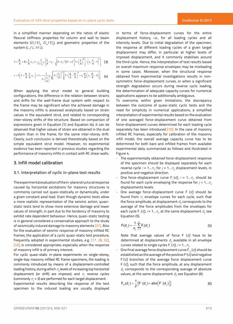
Figure 6. Brick masonry infill: a) Unreinforced infill; b) Reinforced infill (rebars in bed joints); c) Reinforced infill (mesh in the plaster)
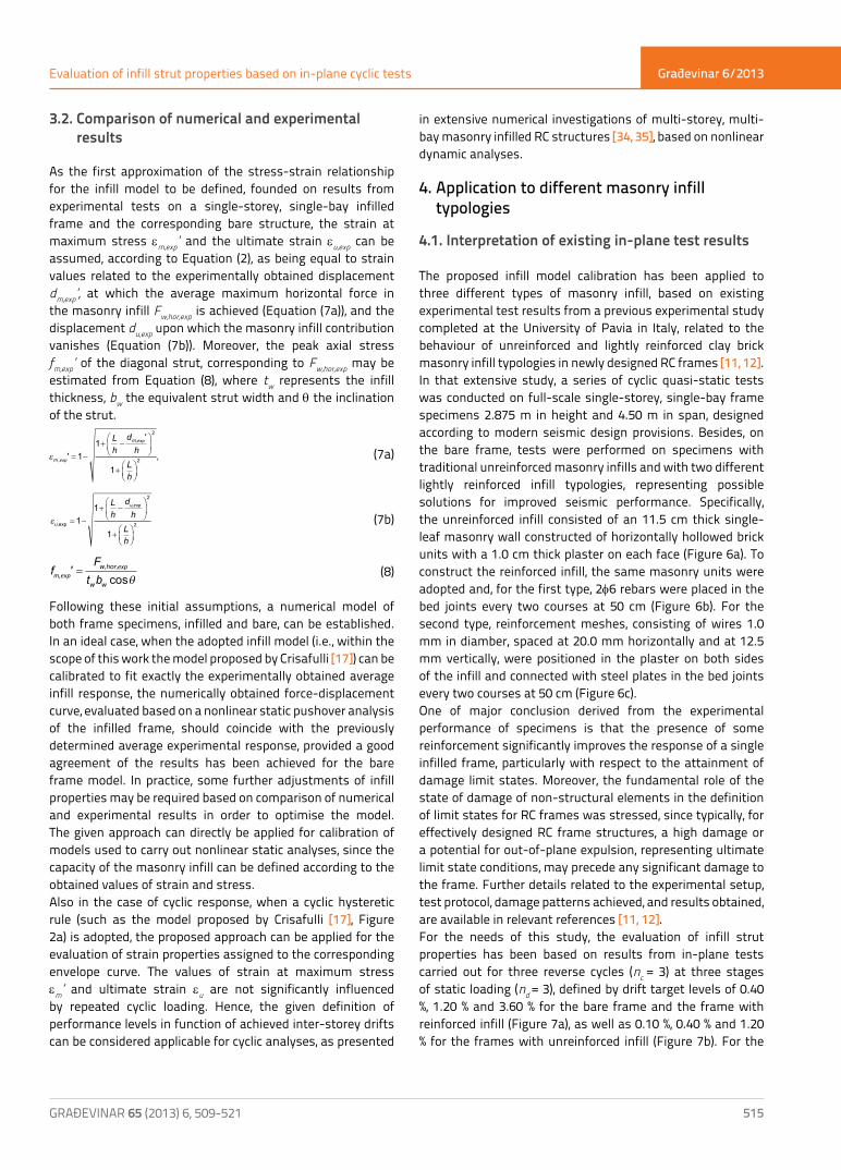
Figure 7. Loading history: a) Bare frame/ frames with reinforced infill; b) Frame with unreinforced infill
Table 2. Experimentally obtained average force and displacement characteristics
Infill typology Fmax,exp[kN]
dmax,exp[mm]
Fw,hor,exp[kN]
dm,exp’[mm]
du,exp[mm]
Unreinforced infill 196.0 11.0 118.0 7.4 35
Lightly reinforced infill(rebars in bed joints) 233.0 14.0 140.0 9.3 38
Lightly reinforced infill(mesh in plaster) 280.0 23.0 158.0 13.0 -

Građevinar 6/2013
517GRAĐEVINAR 65 (2013) 6, 509-521
Evaluation of infill strut properties based on in-plane cyclic tests
Figure 8. Interpretation of test results: a) Bare frame; b) Unreinforced infill; c) Reinforced infill (rebars in bed joints); d) Reinforced infill (mesh in the plaster)
Figure 9. Average experimental capacity: a) Unreinforced infill; b) Reinforced infill (rebars in bed joints); c) Reinforced infill (mesh in the plaster)
Građevinar 6/2013
518 GRAĐEVINAR 65 (2013) 6, 509-521
Sanja Hak, Paolo Morandi, Guido Magenes
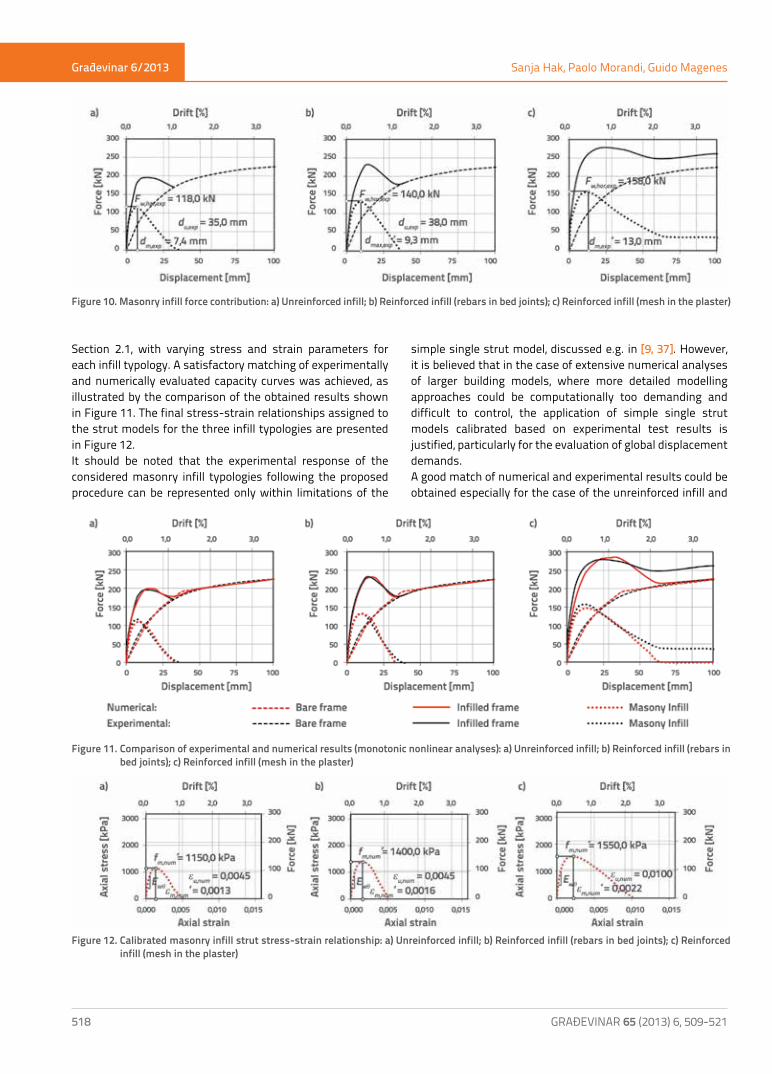
Section 2.1, with varying stress and strain parameters for each infill typology. A satisfactory matching of experimentally and numerically evaluated capacity curves was achieved, as illustrated by the comparison of the obtained results shown in Figure 11. The final stress-strain relationships assigned to the strut models for the three infill typologies are presented in Figure 12.It should be noted that the experimental response of the considered masonry infill typologies following the proposed procedure can be represented only within limitations of the
simple single strut model, discussed e.g. in [9, 37]. However, it is believed that in the case of extensive numerical analyses of larger building models, where more detailed modelling approaches could be computationally too demanding and difficult to control, the application of simple single strut models calibrated based on experimental test results is justified, particularly for the evaluation of global displacement demands.A good match of numerical and experimental results could be obtained especially for the case of the unreinforced infill and
Figure 10. Masonry infill force contribution: a) Unreinforced infill; b) Reinforced infill (rebars in bed joints); c) Reinforced infill (mesh in the plaster)
Figure 11. Comparison of experimental and numerical results (monotonic nonlinear analyses): a) Unreinforced infill; b) Reinforced infill (rebars in bed joints); c) Reinforced infill (mesh in the plaster)
Figure 12. Calibrated masonry infill strut stress-strain relationship: a) Unreinforced infill; b) Reinforced infill (rebars in bed joints); c) Reinforced infill (mesh in the plaster)
Građevinar 6/2013
519GRAĐEVINAR 65 (2013) 6, 509-521
Evaluation of infill strut properties based on in-plane cyclic tests
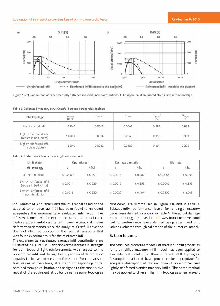
infill reinforced with rebars, and the infill model based on the adopted constitutive law [17] has been found to represent adequately the experimentally evaluated infill action. For infills with mesh reinforcement, the numerical model could capture experimental results with lower accuracy at higher deformation demands, since the analytical Crisafulli envelope does not allow reproduction of the residual resistance that was found experimentally for the reinforced infill. The experimentally evaluated average infill contributions are illustrated in Figure 13a, which shows the increase in strength for both types of light reinforcements with respect to the unreinforced infill and the significantly enhanced deformation capacity in the case of mesh reinforcement. For comparison, final values of the stress, strain and corresponding drifts, obtained through calibration and assigned to the constitutive model of the equivalent strut for three masonry typologies
considered, are summarised in Figure 13a and in Table 3. Subsequently, performance levels for a single masonry panel were defined, as shown in Table 4. The actual damage reported during the tests [11, 12] was found to correspond well to performance levels defined using strain and drift values evaluated through calibration of the numerical model.
5. Conclusions
The described procedure for evaluation of infill strut properties for a simplified masonry infill model has been applied to available test results for three different infill typologies. Assumptions adopted have proven to be appropriate for adequate description of the response of unreinforced and lightly reinforced slender masonry infills. The same method may be applied to other similar infill typologies when relevant
Figure 13. a) Comparison of experimentally obtained masonry infill contributions; b) Comparison of calibrated stress-strain relationships
Infill typology fm,num’[kPa]
εm,num’
εu,num
δm,num’[%]
δu,num[%]
Unreinforced infill 1150.0 0.0013 0.0045 0.287 0.993
Lightly reinforced infill(rebars in bed joints) 1400.0 0.0016 0.0045 0.353 0.993
Lightly reinforced infill(mesh in plaster) 1550.0 0.0022 0.0100 0.494 2.205
Table 3. Calibrated masonry strut Crisafulli stress-strain relationships
Table 4. Performance levels for a single masonry infill
Limit state Operational Damage Limitation UltimateInfill typology ε δ [%] ε δ [%] ε δ [%]
Unreinforced infill ≤ 0.0009 ≤ 0.191 ≤ 0.0013 ≤ 0.287 ≤ 0.0045 ≤ 0.993
Lightly reinforced infill(rebars in bed joints) ≤ 0.0011 ≤ 0.235 ≤ 0.0016 ≤ 0.353 ≤ 0.0045 ≤ 0.993
Lightly reinforced infill(mesh in plaster) ≤ 0.0015 ≤ 0.329 ≤ 0.0022 ≤ 0.494 ≤ 0.0100 ≤ 2.205
Građevinar 6/2013
520 GRAĐEVINAR 65 (2013) 6, 509-521
Sanja Hak, Paolo Morandi, Guido Magenes
experimental results from cyclic quasi-static tests are available. A slight disagreement of the adopted model with respect to the experimental response has been observed in the case of mesh reinforcement applied in the plaster of the infill due to the remaining residual strength at higher levels of in-plane drift. This fact indicates that the application of a different constitutive law may be more suitable for some types of infill with significantly different strength and stiffness properties. However, the same procedure based on interpretation of experimental results and their comparison to the response of the numerical model can be adopted. In addition, this simplified approach is primarily applicable to infill types for which a predominantly symmetric response is expected, and the development of mostly independent failure modes for the positive and negative directions of in-plane loading can be assumed.Results obtained allow application of calibrated models for extensive numerical analyses, and the numerical assessment of the infill damage based on the defined performance levels as a function of achieved strain and/or drift amplitudes. Moreover, a simple comparison of strength and deformation properties of different types of infills can be made based on the proposed procedure, which allows consistent interpretation and application of experimental data. In particular, traditional slender masonry infills built with hollow clay units are studied in this paper through interpretation of existing test results. Based on evaluation of an average infill response, new conclusions have been derived related to the increase in strength and deformation capacity of the infill due to the presence of light reinforcement, compared
to unreinforced masonry. Accordingly, the strength increase of about 20 % and 35 % has been obtained for reinforced masonry infills with rebars and mesh reinforcement, respectively, as compared to the unreinforced typology. Furthermore, a significant improvement of the deformation capacity due to the presence of light reinforcement has been noted. In terms of drift at maximum resistance, an increase of more than 20 % and 70 %, respectively, has been observed for the two types of reinforced infill. It has also been established that the ultimate drift sustained by the infill before failure has not been influenced by the presence of rebars. On the other hand, the resistance has been largely increased due to the application of mesh reinforcement.Following the proposed approach for the case of other unreinforced masonry infill solutions, such as the contemporary strong block masonry infill typologies, commonly adopted for external building enclosures, higher levels of deformation capacity with respect to the slender unreinforced type of infill may be expected. Further relevant data are currently being collected in the scope of an extensive experimental campaign that is in progress at the University of Pavia and at the Eucentre of Pavia in Italy.
Acknowledgements
This work, conducted at the University of Pavia and at Eucentre of Pavia in Italy, was funded by the ANDIL Assolaterizi and through the Executive Project DPC-RELUIS 2010-2013, task AT2-1.3. The financial support received is gratefully acknowledged.
REFERENCES[1] Mehrabi, A. B. & Shing, P. B.: Finite element modeling of
masonry-infilled RC frames, Journal of Structural Engineering, 123:5, pp. 604-613, 1997.
[2] Asteris, P.G.: Finite element micro-modeling of infilled frames, Electronic Journal of Structural Engineering, 8, pp. 1-11, 2008.
[3] Hak, S., Morandi, P. & Magenes, G.: Local effects in the seismic design of RC frame structures with masonry infills, 4th ECCOMAS Thematic Conference on Computational Methods in Structural Dynamics and Earthquake Engineering, Kos Island, 2013.
[4] Braga, F., Manfredi, V., Masi, A., Salvatori, A. & Vona, M.: Performance of non-structural elements in RC buildings during the L’Aquila 2009 earthquake, Bulletin of Earthquake Engineering, 9, 307-324, 2011.
[5] Magenes, G., Bracchi, S., Graziotti, F., Mandirola, M., Manzini, C.F., Morandi, P., Palmieri, M., Penna, A., Rosti, A., Rota, M. & Tondelli, M.: Rapporto preliminare sul rilevo dei danni alle strutture in muratura dopo i terremoti dell’Emilia del Maggio 2012, v.1, http://www.eqclearinghouse.org/2012-05-20-italy-it/.
[6] Morandi, P., Hak, S. & Magenes, G.: Simplified Out-of-plane Resistance Verification for Slender Clay Masonry Infills in RC Frames, 15th National Conference ANIDIS, Padova, 2013.
[7] Drysdale, R.G., Hamid, A.A. & Baker, L.R.: Masonry structures: behavior and design, The Masonry Society, Boulder, Colorado, 1999.
[8] Angel, R., Abrams, D., Shapiro, D., Uzarski, J. & Webster, M.: Behaviour of reinforced concrete frames with masonry infills. Research Report, University of Illinois, 1994.
[9] Asteris, P.G., Antoniou, S.T., Sophianopoulos, D.S. & Chrysostomou, C.Z.: Mathematical macromodeling of infilled frames: State of the art, Journal of Structural Engineering, 137:12, pp. 1508-1517, 2011.
[10] Hak, S., Morandi, P. & Magenes, G.: Interpretation of in-plane response and definition of damage levels for masonry infilled RC frames, 15th International Brick and Block Masonry Conference, Florianópolis, 2012.

Građevinar 6/2013
521GRAĐEVINAR 65 (2013) 6, 509-521
Evaluation of infill strut properties based on in-plane cyclic tests
[11] Calvi, G.M. & Bolognini D.: Seismic response of R.C. frames infilled with weakly reinforced hollow masonry panels, Research Report, University of Pavia, 1999.
[12] Calvi, G.M. & Bolognini D.: Seismic response of RC frames infilled with weakly reinforced masonry panels, Journal of Earthquake Engineering, Vol. 5, No. 2, pp. 153-185, 2001.
[13] Giberson, M.F.: The response of nonlinear multi-story structures subjected to earthquake excitation, EERL Report, California Institute of Technology, 1967.
[14] Otani, S.: Hysteresis models of reinforced concrete for earthquake response analysis, Journal of the Faculty of Engineering of the University of Tokyo, 36:2, pp. 125-159, 1981.
[15] Ramberg, W. & Osgood, W.R.: Description of stress-strain curves by three parameters, National Advisory Committee on Aeronautics, Technical Note 902, 1943.
[16] Klingner, R.E. & Bertero, V.V.: Infilled frames in earthquake resistant construction, Report No. EERC 76-32, University of California, 1976.
[17] Crisafulli, F.J.: Seismic behaviour of reinforced concrete structures with masonry infills, PhD Dissertation, University of Canterbury, 1997.
[18] Rodrigues, H., Varum, H. & Costa, A.: Simplified macro-model for infill masonry panels, Journal of Earthquake Engineering, 14:3, pp. 390- 416, 2010.
[19] Fardis, M.N.: Seismic design issues for masonry-infilled RC frames, 1st European Conference on Earthquake Engineering and Seismology, Geneva, 2006.
[20] Decanini, L.D., Bertoldi, S.H. & Gavarini, C.: Telai tamponati soggetti ad azione sismica, un modello semplificato: confronto sperimentale e numerico (in Italian), 6th National Conference ANIDIS, Perugia, 1993.
[21] CEN: Eurocode 8 EN 1998-1, Design of structures for earthquake resistance, Part 1: General rules, seismic actions and rules for buildings, European Committee for Standardisation, Brussels, 2004.
[22] IBC 2012 edition: International Building Code, International Code Council, 2012.
[23] ASCE Standard ASCE/SEI 7-10: Minimum Design Loads for Buildings and Other Structures, American Society of Civil Engineers, 2010.
[24] NBCC 2010 edition: National Building Code of Canada, National Research Council, 2010.
[25] NZS 1170.5:2004: Structural Design Actions – Part 5: Earthquake Acitons New Zealand, Standards Council New Zealand, 2004.
[26] FEMA 306: Evaluation of Earthquake Damaged Concrete and Masonry Wall Buildings - Basic Procedures Manual, Federal Emergency Management Agency, 1998.
[27] FEMA 307: Evaluation of Earthquake Damaged Concrete and Masonry Wall Buildings – Tecnical Resources, Federal Emergency Management Agency, 1998.
[28] Mehrabi, A.B., Shing, P.B., Schuller, M.P. & Noland, J.L.: Experimental evaluation of masonry infilled frames, Journal of Structural Engineering, 122:2, pp. 228-237, 1996.
[29] Combescure, D., Pires, F., Cerqueira, P. & Pegon, P.: Test on masonry infilled RC frames and its numerical interpretation, Proceedings of 11th World Conference on Earthquake Engineering. Acapulco, Mexico, 1996.
[30] Morandi, P., Hak, S. & Magenes, G.: Comportamento sismico delle tamponature in laterizio in telai in c.a.: definizione dei livelli prestazionali e calibrazione di un modello numerico (in Italian), Atti del XIV convegno nazionale ANIDIS, 2011.
[31] Calvi, G.M., Kingsley, M.R. & Magenes, G.: Testing of masonry structures for seismic assessment, Earthquake Spectra, 12:1, pp. 145-162, 1996.
[32] Durrani, A.J. & Haider, S.: Seismic response of RC frames with unreinforced masonry infills, 14th World Conference on Earthquake Engineering, Acapulco, 1996.
[33] Kakaletsis, D.J. & Karayannis, C.G.: Influence of masonry strength and openings on infilled RC frames under cyclic loading, Journal of Earthquake Engineering, 12:2, pp. 197-221, 2008.
[34] Morandi, P., Hak, S. & Magenes, G.: Comportamento sismico delle tamponature in laterizio in telai in c.a.: analisi numeriche su edifici ed implicazioni progettuali (in Italian), Atti del XIV convegno nazionale ANIDIS, 2011.
[35] Hak, S., Morandi, P., Magenes, G. & Sullivan, T.: Damage control for clay masonry infills in the design of RC frame structures, Journal of Earthquake Engineering, 16:S1, pp. 1-35, 2012.
[36] Carr, A.J.: Ruaumoko Manual, University of Canterbury, 2007.
[37] Smyrou, E., Blandon, C., Antoniou S., Pinho, R. & Crisafulli, F.J.: Implementation and verification of a masonry panel model for nonlinear dynamic analysis of infilled RC frames, Bulletin of Earthquake Engineering, 9:5, pp. 1519-1534, 2011.