PRIMERGY CX420 S1 Server Enclosure -...
180
Upgrade and Maintenance Manual - English PRIMERGY CX420 S1 Dual Node Cluster Server Upgrade and Maintenance Manual Edition October 2013
Transcript of PRIMERGY CX420 S1 Server Enclosure -...

Upgrade and Maintenance Manual - English
PRIMERGY CX420 S1Dual Node Cluster Server Upgrade and Maintenance Manual
Edition October 2013

Copyright and Trademarks
Comments… Suggestions… Corrections…The User Documentation Department would like toknow your opinion of this manual. Your feedback helpsus optimize our documentation to suit your individual needs.
Feel free to send us your comments by e-mail to [email protected].
Certified documentation according to DIN EN ISO 9001:2008To ensure a consistently high quality standard anduser-friendliness, this documentation was created tomeet the regulations of a quality management system which complies with the requirements of the standardDIN EN ISO 9001:2008.
cognitas. Gesellschaft für Technik-Dokumentation mbHwww.cognitas.de
Copyright © 2013 Fujitsu Technology Solutions GmbH.
All rights reserved.Delivery subject to availability; right of technical modifications reserved.
All hardware and software names used are trademarks of their respective manufacturers.
– The contents of this manual may be revised without prior notice.
– Fujitsu assumes no liability for damages to third party copyrights or other rights arising from the use of any information in this manual.
– No part of this manual may be reproduced in any form without the prior written permission of Fujitsu.
Microsoft, Windows, Windows Server, and Hyper V are trademarks or registered trademarks of Microsoft Corporation in the USA and other countries.
Intel and Xeon are trademarks or registered trademarks of Intel Corporation or its subsidiaries in the USA and other countries.

Before reading this manual
For your safety
This manual contains important information for safely and correctly using this product.
Carefully read the manual before using this product. Pay particular attention to the accompanying manual "Safety Notes and Regulations" and ensure these safety notes are understood before using the product. Keep this manual and the manual "Safety Notes and Regulations" in a safe place for easy reference while using this product.
Radio interference
This product is a "Class A" ITE (Information Technology Equipment). In a domestic environment this product may cause radio interference, in which case the user may be required to take appropriate measures. VCCI-A
Aluminum electrolytic capacitors
The aluminum electrolytic capacitors used in the product's printed circuit board assemblies and in the mouse and keyboard are limited-life components. Use of these components beyond their operating life may result in electrolyte leakage or depletion, potentially causing emission of foul odor or smoke.
As a guideline, in a normal office environment (25°C) operating life is not expected to be reached within the maintenance support period (5 years). However, operating life may be reached more quickly if, for example, the product is used in a hot environment. The customer shall bear the cost of replacing replaceable components which have exceeded their operating life. Note that these are only guidelines, and do not constitute a guarantee of trouble-free operation during the maintenance support period.
High safety use
This product has been designed and manufactured to be used in commercial and/or industrial areas as a server.
When used as visual display workplace, it must not be placed in the direct field of view to avoid incommoding reflections (applies only to TX server systems).
The device has not been designed or manufactured for uses which demand an extremely high level of safety and carry a direct and serious risk of life or body if such safety cannot be assured.
CX420 S1 Upgrade and Maintenance Manual
These uses include control of nuclear reactions in nuclear power plants, automatic airplane flight control, air traffic control, traffic control in mass transport systems, medical devices for life support, and missile guidance control in weapons systems (hereafter, "high safety use"). Customers should not use this product for high safety use unless measures are in place for ensuring the level of safety demanded of such use. Please consult the sales staff of Fujitsu if intending to use this product for high safety use.
Measures against momentary voltage drop
This product may be affected by a momentary voltage drop in the power supply caused by lightning. To prevent a momentary voltage drop, use of an AC uninterruptible power supply is recommended.
(This notice follows the guidelines of Voltage Dip Immunity of Personal Computer issued by JEITA, the Japan Electronics and Information Technology Industries Association.)
Technology controlled by the Foreign Exchange and Foreign Trade Control Law of Japan
Documents produced by Fujitsu may contain technology controlled by the Foreign Exchange and Foreign Trade Control Law of Japan. Documents which contain such technology should not be exported from Japan or transferred to non-residents of Japan without first obtaining authorization in accordance with the above law.
Harmonic Current Standards
This product conforms to harmonic current standard JIS C 61000-3-2.
Only for the Japanese market: About SATA hard disk drives
The SATA version of this server supports hard disk drives with SATA / BC-SATA storage interfaces. Please note that the usage and operation conditions differ depending on the type of hard disk drive used.
Please refer to the following internet address for further information on the usage and operation conditions of each available type of hard disk drive:
http://primeserver.fujitsu.com/primergy/harddisk/
Upgrade and Maintenance Manual CX420 S1

Version history
Version historyIssue number Reason for update1.0 / April 2013 Initial release
CX420 S1 Upgrade and Maintenance Manual

Version history
Upgrade and Maintenance Manual CX420 S1

Content
1 Introduction . . . . . . . . . . . . . . . . . . . . . . . . . . . 13
1.1 Notational conventions . . . . . . . . . . . . . . . . . . . . 14
2 Before you start . . . . . . . . . . . . . . . . . . . . . . . . 15
2.1 Classification of procedures . . . . . . . . . . . . . . . . . 172.1.1 Customer Replaceable Units (CRU) . . . . . . . . . . . . . . . 172.1.2 Field Replaceable Units (FRU) . . . . . . . . . . . . . . . . . 18
2.2 Average task duration . . . . . . . . . . . . . . . . . . . . . 19
2.3 Tools you need at hand . . . . . . . . . . . . . . . . . . . . 202.3.1 For the 3.5-inch chassis . . . . . . . . . . . . . . . . . . . . . 20
2.4 Documents you need at hand . . . . . . . . . . . . . . . . . 212.4.1 Documents for the Dual Node Cluster Server . . . . . . . . . . 222.4.2 Documents for the server nodes . . . . . . . . . . . . . . . . . 23
3 Important information . . . . . . . . . . . . . . . . . . . . . 25
3.1 Safety instructions . . . . . . . . . . . . . . . . . . . . . . . 25
3.2 CE conformity . . . . . . . . . . . . . . . . . . . . . . . . . 31
3.3 FCC Class A Compliance Statement . . . . . . . . . . . . . 32
3.4 Environmental protection . . . . . . . . . . . . . . . . . . . 33
4 Basic hardware procedures . . . . . . . . . . . . . . . . . . 35
4.1 Shutting down the server node . . . . . . . . . . . . . . . . 35
4.2 Disconnecting the power cord . . . . . . . . . . . . . . . . 36
4.3 Removing the Dual Node Cluster Server out of the rack . . 374.3.1 Preliminary steps . . . . . . . . . . . . . . . . . . . . . . . . 374.3.2 Removing the rear fixing brackets . . . . . . . . . . . . . . . . 384.3.3 Removing the Dual Node Cluster Server out of the rack . . . . 39
CX420 S1 Upgrade and Maintenance Manual
Content
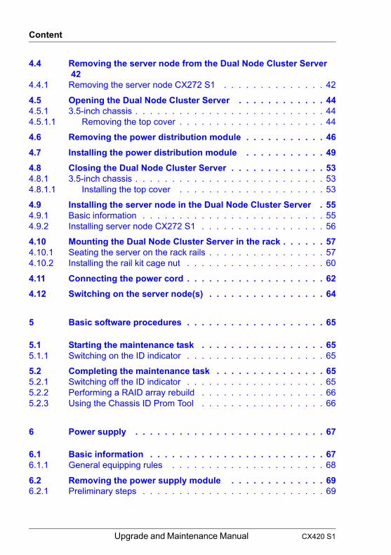
4.4 Removing the server node from the Dual Node Cluster Server 42
4.4.1 Removing the server node CX272 S1 . . . . . . . . . . . . . . 42
4.5 Opening the Dual Node Cluster Server . . . . . . . . . . . . 444.5.1 3.5-inch chassis . . . . . . . . . . . . . . . . . . . . . . . . . . 444.5.1.1 Removing the top cover . . . . . . . . . . . . . . . . . . . . 44
4.6 Removing the power distribution module . . . . . . . . . . . 46
4.7 Installing the power distribution module . . . . . . . . . . . 49
4.8 Closing the Dual Node Cluster Server . . . . . . . . . . . . . 534.8.1 3.5-inch chassis . . . . . . . . . . . . . . . . . . . . . . . . . . 534.8.1.1 Installing the top cover . . . . . . . . . . . . . . . . . . . . 53
4.9 Installing the server node in the Dual Node Cluster Server . 554.9.1 Basic information . . . . . . . . . . . . . . . . . . . . . . . . . 554.9.2 Installing server node CX272 S1 . . . . . . . . . . . . . . . . . 56
4.10 Mounting the Dual Node Cluster Server in the rack . . . . . . 574.10.1 Seating the server on the rack rails . . . . . . . . . . . . . . . . 574.10.2 Installing the rail kit cage nut . . . . . . . . . . . . . . . . . . . 60
4.11 Connecting the power cord . . . . . . . . . . . . . . . . . . . 62
4.12 Switching on the server node(s) . . . . . . . . . . . . . . . . 64
5 Basic software procedures . . . . . . . . . . . . . . . . . . . 65
5.1 Starting the maintenance task . . . . . . . . . . . . . . . . . 655.1.1 Switching on the ID indicator . . . . . . . . . . . . . . . . . . . 65
5.2 Completing the maintenance task . . . . . . . . . . . . . . . 655.2.1 Switching off the ID indicator . . . . . . . . . . . . . . . . . . . 655.2.2 Performing a RAID array rebuild . . . . . . . . . . . . . . . . . 665.2.3 Using the Chassis ID Prom Tool . . . . . . . . . . . . . . . . . 66
6 Power supply . . . . . . . . . . . . . . . . . . . . . . . . . . 67
6.1 Basic information . . . . . . . . . . . . . . . . . . . . . . . . 676.1.1 General equipping rules . . . . . . . . . . . . . . . . . . . . . 68
6.2 Removing the power supply module . . . . . . . . . . . . . 696.2.1 Preliminary steps . . . . . . . . . . . . . . . . . . . . . . . . . 69
Upgrade and Maintenance Manual CX420 S1

Content
6.3 Installing the power supply module . . . . . . . . . . . . . . 716.3.1 Installing the power supply module . . . . . . . . . . . . . . . 716.3.2 Concluding steps . . . . . . . . . . . . . . . . . . . . . . . . 72
6.4 Replacing the power supply module . . . . . . . . . . . . . 736.4.1 Preliminary steps . . . . . . . . . . . . . . . . . . . . . . . . 736.4.2 Removing the defective power supply module . . . . . . . . . 736.4.3 Installing the new power supply module . . . . . . . . . . . . . 746.4.4 Concluding steps . . . . . . . . . . . . . . . . . . . . . . . . 74
6.5 Replacing the power distribution board . . . . . . . . . . . 756.5.1 Replacing the defective top PDB . . . . . . . . . . . . . . . . 756.5.1.1 Preliminary steps . . . . . . . . . . . . . . . . . . . . . . . 756.5.1.2 Removing the top PDB . . . . . . . . . . . . . . . . . . . . 766.5.1.3 Installing the top PDB . . . . . . . . . . . . . . . . . . . . 786.5.1.4 Concluding steps . . . . . . . . . . . . . . . . . . . . . . . 796.5.2 Replacing the defective bottom PDB . . . . . . . . . . . . . . 806.5.2.1 Preliminary steps . . . . . . . . . . . . . . . . . . . . . . . 806.5.2.2 Removing the bottom PDB . . . . . . . . . . . . . . . . . . 816.5.2.3 Installing the bottom PDB . . . . . . . . . . . . . . . . . . 836.5.2.4 Concluding steps . . . . . . . . . . . . . . . . . . . . . . . 85
7 Hard disk drives / solid state drives . . . . . . . . . . . . . . 87
7.1 Basic information . . . . . . . . . . . . . . . . . . . . . . . 887.1.1 General equipping rules . . . . . . . . . . . . . . . . . . . . . 88
7.2 3.5-inch hard disk drives . . . . . . . . . . . . . . . . . . . . 897.2.1 HDD install order in the 3.5-inch chassis . . . . . . . . . . . . 897.2.2 Installing 3.5-inch HDD modules . . . . . . . . . . . . . . . . 907.2.2.1 Preliminary steps . . . . . . . . . . . . . . . . . . . . . . . 907.2.2.2 Removing a 3.5-inch HDD tray . . . . . . . . . . . . . . . . 917.2.2.3 Installing the 3.5-inch HDD module . . . . . . . . . . . . . 927.2.2.4 Concluding steps . . . . . . . . . . . . . . . . . . . . . . . 927.2.3 Removing 3.5-inch HDD modules . . . . . . . . . . . . . . . . 937.2.3.1 Preliminary steps . . . . . . . . . . . . . . . . . . . . . . . 937.2.3.2 Removing a 3.5-inch HDD module . . . . . . . . . . . . . . 947.2.3.3 Installing the 3.5-inch HDD tray . . . . . . . . . . . . . . . 957.2.4 Replacing a 3.5-inch HDD module . . . . . . . . . . . . . . . 967.2.4.1 Preliminary steps . . . . . . . . . . . . . . . . . . . . . . . 967.2.4.2 Removing a 3.5-inch HDD module . . . . . . . . . . . . . . 967.2.4.3 Installing the 3.5-inch HDD module . . . . . . . . . . . . . 977.2.4.4 Concluding steps . . . . . . . . . . . . . . . . . . . . . . . 97
CX420 S1 Upgrade and Maintenance Manual

Content
7.3 Installing a 2.5-inch HDD/SSD in a 3.5-inch tray . . . . . . . . 987.3.1 Removing a 3.5-inch HDD module . . . . . . . . . . . . . . . . 987.3.2 Mounting a 2.5-inch HDD/SSD in a 3.5-inch tray . . . . . . . . . 987.3.3 Installing the 3.5-inch HDD module . . . . . . . . . . . . . . . . 997.3.4 Concluding steps . . . . . . . . . . . . . . . . . . . . . . . . . 99
7.4 Replacing HDD/SSD SAS/SATA backplanes . . . . . . . . . 1007.4.1 Replacing the 3.5-inch HDD SAS/SATA backplane . . . . . . . 1007.4.1.1 Preliminary steps . . . . . . . . . . . . . . . . . . . . . . 1007.4.1.2 Removing the 3.5-inch HDD SAS / SATA backplane . . . . 1017.4.1.3 Installing the 3.5-inch HDD SAS/SATA backplane . . . . . 1037.4.1.4 Concluding steps . . . . . . . . . . . . . . . . . . . . . . 104
7.5 Configuration and management of virtual disks in storage spaces . . . . . . . . . . . . . . . . . . . . . . . . . . . . . 105
7.5.1 Error situations . . . . . . . . . . . . . . . . . . . . . . . . . 1057.5.1.1 Less severe errors . . . . . . . . . . . . . . . . . . . . . 1057.5.1.2 Severe errors . . . . . . . . . . . . . . . . . . . . . . . . 1077.5.2 Disk Error Details . . . . . . . . . . . . . . . . . . . . . . . . 1087.5.3 Storage Spaces Event Logging . . . . . . . . . . . . . . . . . 1097.5.4 Transitional Errors . . . . . . . . . . . . . . . . . . . . . . . 1097.5.5 Automatic Email Notification . . . . . . . . . . . . . . . . . . 110
8 System fan . . . . . . . . . . . . . . . . . . . . . . . . . . . 113
8.1 Basic Information . . . . . . . . . . . . . . . . . . . . . . . 114
8.2 Replacing the fan in the fan module . . . . . . . . . . . . . 1168.2.1 Preliminary steps . . . . . . . . . . . . . . . . . . . . . . . . 1168.2.2 Removing the fan module . . . . . . . . . . . . . . . . . . . . 1178.2.3 Removing the fan from the fan holder . . . . . . . . . . . . . 1198.2.4 Installing fan1 and fan2 . . . . . . . . . . . . . . . . . . . . . 1218.2.4.1 Installing the fan1 . . . . . . . . . . . . . . . . . . . . . . 1228.2.4.2 Installing the fan2 . . . . . . . . . . . . . . . . . . . . . . 1238.2.5 Installing fan3 and fan4 . . . . . . . . . . . . . . . . . . . . . 1248.2.5.1 Installing the fan4 . . . . . . . . . . . . . . . . . . . . . . 1258.2.5.2 Installing the fan3 . . . . . . . . . . . . . . . . . . . . . . 1268.2.6 Installing the fan module . . . . . . . . . . . . . . . . . . . . 1278.2.7 Concluding steps . . . . . . . . . . . . . . . . . . . . . . . . 129
Upgrade and Maintenance Manual CX420 S1

Content
9 Midplane . . . . . . . . . . . . . . . . . . . . . . . . . . . . 131
9.1 Replacing the midplane . . . . . . . . . . . . . . . . . . . . 1329.1.1 Preliminary steps . . . . . . . . . . . . . . . . . . . . . . . . 1329.1.2 Removing the midplane . . . . . . . . . . . . . . . . . . . . . 1339.1.3 Installing the midplane . . . . . . . . . . . . . . . . . . . . . . 1359.1.4 Concluding steps . . . . . . . . . . . . . . . . . . . . . . . . 138
10 Linking boards . . . . . . . . . . . . . . . . . . . . . . . . . 139
10.1 Linking boards in 3.5-inch HDD chassis . . . . . . . . . . . 14010.1.1 Basic information . . . . . . . . . . . . . . . . . . . . . . . . 14010.1.2 Replacing the linking board . . . . . . . . . . . . . . . . . . . 14110.1.2.1 Preliminary steps . . . . . . . . . . . . . . . . . . . . . . . 14110.1.2.2 Removing the linking board . . . . . . . . . . . . . . . . . 14210.1.2.3 Installing the linking board . . . . . . . . . . . . . . . . . . 14310.1.2.4 Concluding steps . . . . . . . . . . . . . . . . . . . . . . . 145
11 Front panel . . . . . . . . . . . . . . . . . . . . . . . . . . . 147
11.1 Replacing the front panel board . . . . . . . . . . . . . . . . 14811.1.1 Preliminary steps . . . . . . . . . . . . . . . . . . . . . . . . 14811.1.2 Removing the front ear bracket . . . . . . . . . . . . . . . . . 14911.1.3 Removing the front panel board . . . . . . . . . . . . . . . . . 15011.1.4 Installing the front panel board . . . . . . . . . . . . . . . . . . 15311.1.5 Installing the front ear bracket . . . . . . . . . . . . . . . . . . 15711.1.6 Concluding steps . . . . . . . . . . . . . . . . . . . . . . . . 158
11.2 Replacing the front panel cable . . . . . . . . . . . . . . . . 15911.2.1 Preliminary steps . . . . . . . . . . . . . . . . . . . . . . . . 15911.2.2 Removing the front panel cable . . . . . . . . . . . . . . . . . 16011.2.3 Installing the front panel cable . . . . . . . . . . . . . . . . . . 16111.2.4 Routing of the front panel cable . . . . . . . . . . . . . . . . . 16211.2.5 Concluding steps . . . . . . . . . . . . . . . . . . . . . . . . 162
12 Cabling . . . . . . . . . . . . . . . . . . . . . . . . . . . . . 165
12.1 Cabling overview . . . . . . . . . . . . . . . . . . . . . . . . 165
12.2 Connectors on the boards . . . . . . . . . . . . . . . . . . . 166
CX420 S1 Upgrade and Maintenance Manual

Content
12.3 Cabling . . . . . . . . . . . . . . . . . . . . . . . . . . . . . 169
13 Appendix . . . . . . . . . . . . . . . . . . . . . . . . . . . . 171
13.1 Mechanical overview . . . . . . . . . . . . . . . . . . . . . 17113.1.1 Multi-node server system front
3.5 inch HDD model . . . . . . . . . . . . . . . . . . . . . . 17113.1.2 Multi-node server system rear . . . . . . . . . . . . . . . . . 17213.1.2.1 CX420 S1 Dual Node Cluster Server with CX272 S1 server
nodes . . . . . . . . . . . . . . . . . . . . . . . . . . . . 17213.1.3 Multi-node server system interior . . . . . . . . . . . . . . . . 17313.1.3.1 3.5-inch HDD model . . . . . . . . . . . . . . . . . . . . . 173
13.2 Controls and indicators . . . . . . . . . . . . . . . . . . . . 17413.2.1 Front panel . . . . . . . . . . . . . . . . . . . . . . . . . . . 17413.2.1.1 Controls on the front panel . . . . . . . . . . . . . . . . . 17513.2.1.2 Indicators on the front panel . . . . . . . . . . . . . . . . . 17513.2.2 Hard disk drives . . . . . . . . . . . . . . . . . . . . . . . . . 17613.2.2.1 Indicators on the hard disk drives . . . . . . . . . . . . . . 17613.2.3 Power supply module . . . . . . . . . . . . . . . . . . . . . . 17713.2.3.1 Indicator on hot-plug power supply module . . . . . . . . . 17713.2.4 Server nodes . . . . . . . . . . . . . . . . . . . . . . . . . . 177
13.3 Minimum startup configuration . . . . . . . . . . . . . . . . 178
Upgrade and Maintenance Manual CX420 S1

1 IntroductionThis Upgrade and Maintenance Manual provides instructions for the following procedures:
● Upgrading the server configuration by adding optional hardware components
● Upgrading the server configuration by replacing existing hardware components with superior ones.
● Replacing defective hardware components
This manual focuses on on-site maintenance tasks. It is recommended to prepare each service assignment following remote diagnostics procedures, as described in the "ServerView Suite Local Service Concept (LSC)" manual (see section "Documents you need at hand" on page 21.
V CAUTION!
The document at hand comprises procedures of a wide range of complexity. Check the profile of qualification for technicians before assigning tasks. Before you start, carefully read "Classification of procedures" on page 17.
CX420 S1 Upgrade and Maintenance Manual 13

Introduction
1.1 Notational conventions
The following notational conventions are used in this manual:
Text in italics indicates commands or menu itemsfixed font indicates system outputsemi-bold fixed font
indicates text to be entered by the user
"Quotation marks" indicate names of chapters and terms that are being emphasized
Ê describes activities that must be performed in the order shown
[Abc] indicates keys on the keyboardV CAUTION! Pay particular attention to texts marked with this symbol!
Failure to observe this warning may endanger your life, destroy the system or lead to the loss of data.
I indicates additional information, notes and tips
indicates the procedure category in terms of complexity and qualification requirements, see "Classification of procedures" on page 17
indicates the average task duration, see "Average task duration" on page 19
14 Upgrade and Maintenance Manual CX420 S1

2 Before you startBefore you start any upgrade or maintenance task, please proceed as follows:
Ê Carefully read the safety instructions in chapter "Important information" on page 25.
Ê Make sure that all necessary manuals are available. Refer to the documentation overview in section "Documents you need at hand" on page 21. Print the PDF files if required.
Ê Make yourself familiar with the procedure categories introduced in section "Classification of procedures" on page 17.
Ê Ensure that all required tools are available according to section "Tools you need at hand" on page 20.
Installing optional components
The "PRIMERGY CX420 S1 Dual Node Cluster Server Operating Manual" gives an introduction to server features and provides an overview of available hardware options.
Use the Fujitsu ServerView Suite management software to prepare hardware expansions. ServerView Suite documentation is available online at http://manuals.ts.fujitsu.com (http://jp.fujitsu.com/platform/server/primergy/system/ for the Japanese market) or from the ServerView Suite DVD 2 supplied with your PRIMERGY server. Please refer to the following ServerView Suite topics:
– Operation– Virtualization– Maintenance
I For the latest information on hardware options, refer to your server’s hardware configurator available online at the following address:
for the EMEA market:http://ts.fujitsu.com/products/standard_servers/tower/primergy_tx140s1.html
for the Japanese market:http://jp.fujitsu.com/platform/server/primergy/system/
CX420 S1 Upgrade and Maintenance Manual 15

Before you start
Please contact your local Fujitsu customer service partner for details on how to order expansion kits or spare parts. Use the Fujitsu Illustrated Spares Catalog to identify the required spare part and obtain technical data and order information. Illustrated Spares catalogs are available online at http://manuals.ts.fujitsu.com/illustrated_spares (EMEA market only).
Replacing a defective component
The global error indicators on the front and rear sides of the server as well as local diagnostic LEDs on the front panel report defective hardware components that need to be replaced. For further information on the controls and indicators of your server, refer to the operating manual of your server and section "Controls and indicators" on page 174.
If the system has been powered off in order to replace a non-hot plug unit, a system of PRIMERGY diagnostic indicators guides you to the defective component. The "Indicate CSS" button enables the indicator next to the defective component even if the server has been switched off and disconnected from the mains.
If the defective component is a customer replaceable unit included in the CSS concept (Customer Self Service, only available for EMEA market), the CSS indicators on the front and rear side of the server will light up.
It is recommended to prepare local maintenance tasks using remote diagnostics procedures, as described in the "ServerView Suite Local Service Concept (LSC)" manual.
16 Upgrade and Maintenance Manual CX420 S1

Before you start
2.1 Classification of procedures
The complexity of maintenance procedures varies significantly. Procedures have been assigned to one of three unit categories, indicating the level of difficulty and required qualification.
At the beginning of each procedure, the involved unit type is indicated by one of the symbols introduced in this section.
I Please ask your local Fujitsu service center for more detailed information.
2.1.1 Customer Replaceable Units (CRU)
Customer Replaceable Units are intended for customer self service and may be installed or replaced as hot-plug components during operation.
I Components that the customer is entitled to replace may differ according to the service form in his country.
Hot-plug components increase system availability and guarantee a high degree of data integrity and fail-safe performance. Procedures can be carried out without shutting down the server or going offline.
Components that are handled as Customer Replaceable Units
– Hot-plug power supply units– Hot-plug HDD / SSD modules
Peripherals that are handled as Customer Replaceable Units
– Keyboard– Mouse
Customer Replaceable Units (CRU)
CX420 S1 Upgrade and Maintenance Manual 17

Before you start
2.1.2 Field Replaceable Units (FRU)
Removing and installing Field Replaceable Units involves complex maintenance procedures on integral server components. Procedures will require shutting down, opening and disassembling the server.
V CAUTION!
Maintenance procedures involving Field Replaceable Units must be performed exclusively by Fujitsu service personnel or technicians trained by Fujitsu. Please note that unauthorized interference with the system will void the warranty and exempt the manufacturer from all liability.
Field Replaceable Units (FRU)
18 Upgrade and Maintenance Manual CX420 S1

Before you start
2.2 Average task duration
The average task duration including preliminary and concluding steps is indicated at the beginning of each procedure next to the procedure class.
Refer to table 1 on page 19 for an overview of steps taken into account for calculating the average task duration:
Average task duration: 10 minutes
Step included Explanation
Server shutdown no
Shutdown time depends on hardware and software configuration and may vary significantly.
Software tasks necessary before maintenance are described in section "Starting the maintenance task" on page 65".
Rack removal, disassembly yes Making the server available, removing the
server from the rack (if applicable)
Transport noTransporting the server to the service table (where required) depends on local customer conditions.
Maintenance procedures yes Maintenance procedures including
preliminary and concluding software tasks
Transport noReturning the server to its installation site (where required) depends on local customer conditions.
Assembly, rack installation yes Reassembling the server, installing the
server in the rack (if applicable)
Starting up noBooting time depends on hardware and software configuration and may vary significantly.
Table 1: Calculation of the average task duration
CX420 S1 Upgrade and Maintenance Manual 19

Before you start
2.3 Tools you need at hand
When preparing the maintenance task, ensure that all required tools are available according to the overview below. You will find a list of required tools at the beginning of each procedure.
2.3.1 For the 3.5-inch chassis
Screw driver / Bit insert Screw Usage Type
PhillipsPH1 / (+) No. 1 Chassis
M3 x 3.0 mm
MS30030FEL0
PhillipsPH2 / (+) No. 2hexagonal cross SW5 / PZ2
Chassis, HDD tray
6-32 x 5.0 mm
MS06050FD40
PhillipsPH2 / (+) No. 2hexagonal cross SW5 / PZ2
Chassis, HDD backplane, PDB boards
6-32 x 4.7 mm
MU0603EHDD1
PhillipsPH2 / (+) No. 2hexagonal cross SW5 / PZ2
Chassis6-32 x 3.5 mm
MS06025FD10
PhillipsPH2 / (+) No. 2hexagonal cross SW5 / PZ2
Chassis6-32 x 4.0 mm
MS06010I000
Table 2: List of required tools and used screws for the 3.5-inch chassis
20 Upgrade and Maintenance Manual CX420 S1

Before you start
2.4 Documents you need at hand
Maintenance procedures may include references to additional documentation. When preparing the maintenance task, ensure that all required manuals are available according to the overview below.
I – Ensure to store all printed manuals enclosed with your server in a save place for future reference.
– Unless stated otherwise, all manuals are available online at http://manuals.ts.fujitsu.com under Industry standard servers or from the ServerView Suite DVD 2 supplied with your PRIMERGY server.
For the Japanese market please use the following address: http://jp.fujitsu.com/platform/server/primergy/manual/
PhillipsPH2 / (+) No. 2 Midplane
MU06055BCI0
6-32 x 5.5 mm
PhillipsPH2 / (+) No. 2 Front panel 6-32 x 5.0
mmMU06050IBJ1
PhillipsPH2 / (+) No. 2 system fans
M5 x 10 mm
MS50100I010
Screw driver / Bit insert Screw Usage Type
Table 2: List of required tools and used screws for the 3.5-inch chassis
CX420 S1 Upgrade and Maintenance Manual 21

Before you start
2.4.1 Documents for the Dual Node Cluster Server
Document Description"Quick Start Hardware - PRIMERGY CX420 S1" leaflet
Quick installation poster for initial operation, available only in printed form
"PRIMERGY ServerView Suite - Overview & Installation" DVD booklet
DVD booklet on initial software configuration included as a printed copy with the ServerView Suite
"Safety notes and regulations" manual
" 安全上のご注意 " for the Japanese market
Important safety information, available from the ServerView Suite DVD 2, online, or as a printed copy
"PRIMERGY CX420 S1 Dual Node Cluster Server Operating Manual"
available from the ServerView Suite DVD 2 or online
System board and service labelsLabels inside the side / top server cover outlining connectors, indicators and basic maintenance tasks
Software documentation
– "ServerView Suite Local Service Concept (LSC)" user guide
– "ServerView Operations Manager - Server Management" user guide
Illustrated Spares catalog
Spare parts identification and information system (EMEA market only), available for online use or download (Windows OS) at http://manuals.ts.fujitsu.com/illustrated_spares or from the CSS component view of the ServerView Operations Manager
Glossary available from the ServerView Suite DVD 2 or online
"Warranty" manual
" 保証書 " for the Japanese market
Important information on warranty regulations, recycling and service, available from the ServerView Suite DVD 2, online, or as a printed copy
Table 3: Documentation you need at hand for the Dual Node Cluster Server
22 Upgrade and Maintenance Manual CX420 S1

Before you start
2.4.2 Documents for the server nodes
"Returning used devices" manual Recycling and contact information,
available from the ServerView Suite DVD 2, online, or as a printed copy
"Service Desk" leaflet
" サポート&サービス " for the Japanese market
Additional documentation
– RAID documentation, available online at http://manuals.ts.fujitsu.com under Industry standard servers - Expansion Cards - Storage Adapters
– Rack documentation
Third party documentation– Operating system documentation,
online help
– Peripherals documentation
Document Description"PRIMERGY CX272 S1 Server Node Operating Manual"
available from the ServerView Suite DVD 2 or online
"PRIMERGY CX272 S1 Server Node Upgrade and Maintenance Manual"
available from the ServerView Suite DVD 2 or online
"D3306 BIOS Setup Utility for PRIMERGY CX272 S1 Reference Manual"
Information on configurable BIOS options and parameters, available from the ServerView Suite DVD 2 or online
Table 4: Documentation you need at hand for the server nodes
Document Description
Table 3: Documentation you need at hand for the Dual Node Cluster Server
CX420 S1 Upgrade and Maintenance Manual 23

Before you start
24 Upgrade and Maintenance Manual CX420 S1

3 Important informationV CAUTION!
Before installing and starting up a device, please observe the safety instructions listed in the following section. This will help you to avoid making serious errors that could impair your health, damage the device and endanger the data base.
I Keep this manual and the other documentation (such as the technical manual, documentation DVD) close to the device. All documentation must be included if the equipment is passed on to a third party.
3.1 Safety instructions
I The following safety instructions are also provided in the manual "Safety Notes and Regulations" or " 安全上のご注意 ".
This device meets the relevant safety regulations for IT equipment. If you have any questions about whether you can install the server in the intended environment, please contact your sales outlet or our customer service team.
● The actions described in this manual shall be performed by technical specialists. A technical specialist is a person who is trained to install the server including hardware and software.
● Repairs to the device that do not relate to CSS failures shall be performed by service personnel. Please note that unauthorized interference with the system will void the warranty and exempt the manufacturer from all liability.
● Any failure to observe the guidelines in this manual, and any improper repairs could expose the user to risks (electric shock, energy hazards, fire hazards) or damage the equipment.
● Before installing/removing internal options to/from the server, turn off the server, all peripheral devices, and any other connected devices. Also unplug all power cords from the power outlet. Failure to do so can cause electric shock or damage.
Before starting up
● During installation and before operating the device, observe the instructions on environmental conditions for your device.
CX420 S1 Upgrade and Maintenance Manual 25

Important information
● If the device is brought in from a cold environment, condensation may form both inside and on the outside of the device.
Wait until the device has acclimatized to room temperature and is absolutely dry before starting it up. Material damage may be caused to the device if this requirement is not observed.
● Transport the device only in the original packaging or in packaging that protects it from knocks and jolts.For the Japanese market, transporting the device in its original packaging does not apply.
Installation and operation
● This unit should not be operated in ambient temperatures above 35 °C.
● If the unit is integrated into an installation that draws power from an industrial power supply network with an IEC309 connector, the power supply's fuse protection must comply with the requirements for non-industrial power supply networks for type A connectors.
● The unit automatically adjusts itself to a mains voltage in a range of 200 VAC to 240 VAC (High Line) or 100 VAC to 240 VAC (Wide Range); depends on which PSU option is used. Ensure that the local mains voltage lies within these limits.
● This device must only be connected to properly grounded power outlets or connected to the grounded rack internal power distribution system with tested and approved power cords.
● Ensure that the device is connected to a properly grounded power outlet close to the device.
● Ensure that the power sockets on the device and the properly grounded power outlets are easily accessible.
● The On/Off button or the main power switch (if present) does not isolate the device from the mains power supply. In case of repair or servicing disconnect the device completely from the mains power supply, unplug all power plugs from the properly grounded power outlets.
● Always connect the server and the attached peripherals to the same power circuit. Otherwise you run the risk of losing data if, for example, the server is still running but a peripheral device (e.g. memory subsystem) fails during a power outage.
● Data cables must be adequately shielded.
26 Upgrade and Maintenance Manual CX420 S1

Important information
● Ethernet cabling has to comply with EN 50173 and EN 50174-1/2 standards or ISO/IEC 11801 standard respectively. The minimum requirement is a Category 5 shielded cable for 10/100 Ethernet, or a Category 5e cable for Gigabit Ethernet.
● Route the cables in such a way that they do not create a potential hazard (make sure no-one can trip over them) and that they cannot be damaged. When connecting the server, refer to the relevant instructions in this manual.
● Never connect or disconnect data transmission lines during a storm (risk of lightning hazard).
● Make sure that no objects (e.g. jewelry, paperclips etc.) or liquids can get inside the server (risk of electric shock, short circuit).
● In emergencies (e.g. damaged casing, controls or cables, penetration of liquids or foreign bodies), contact the system administrator or your customer service team. Only disconnect the system from the mains power supply if there is no risk of harming yourself.
● Proper operation of the system (in accordance with IEC 60950-1 resp. EN 60950-1) is only ensured if the casing is completely assembled and the rear covers for the installation slots have been fitted (electric shock, cooling, fire protection, interference suppression).
● Only install system expansions that satisfy the requirements and rules governing safety and electromagnetic compatibility and those relating to telecommunication terminals. If you install other expansions, they may damage the system or violate the safety regulations. Information on which system expansions are approved for installation can be obtained from our customer service center or your sales outlet.
● The components marked with a warning notice (e.g. lightning symbol) may only be opened, removed or exchanged by authorized, qualified personnel. Exception: CSS components can be replaced.
● The warranty is void if the server is damaged during installation or replacement of system expansions.
● Only set screen resolutions and refresh rates that are specified in the operating manual for the monitor. Otherwise, you may damage your monitor. If you are in any doubt, contact your sales outlet or customer service center.
● Before installing/removing internal options to/from the server, turn off the server, all peripheral devices, and any other connected devices. Also unplug all power cords from the outlet. Failure to do so can cause electric shock.
CX420 S1 Upgrade and Maintenance Manual 27

Important information
● Do not damage or modify internal cables or devices. Doing so may cause a device failure, fire, or electric shock and will void the warranty and exempt the manufacturer from all liability.
● Devices inside the server remain hot after shutdown. Wait for a while after shutdown before installing or removing internal options.
● The circuit boards and soldered parts of internal options are exposed and can be damaged by static electricity. To ensure reliable protection, if you are wearing an earthing band on your wrist when working with this type of module, connect it to an unpainted, non-conducting metal part of the system.
● Do not touch the circuitry on boards or soldered parts. Hold the metallic areas or the edges of the circuit boards.
● Install the screw removed during installation/detaching internal options in former device/position. To use a screw of the different kind can cause a breakdown of equipment.
● The installation indicated on this document is sometimes changed to the kind of possible options without notice.
Modules with Electrostatic-Sensitive Devices
Modules with electrostatic-sensitive devices are identified by the following sticker:
Figure 1: ESD label
When you handle components fitted with ESDs, you must always observe the following points:
● Switch off the system and remove the power plugs from the power outlets before installing or removing components with ESDs.
28 Upgrade and Maintenance Manual CX420 S1

Important information
● The circuit boards and soldered parts of internal options are exposed and can be damaged by static electricity. To ensure reliable protection, you must wear an earthing band on your wrist when working with this type of module and connect it to an unpainted, non-conducting metal part of the system.
● Any devices or tools that are used must be free of electrostatic charge.
● Wear a suitable grounding cable that connects you to the external chassis of the system unit.
● Always hold components with ESDs at the edges or at the points marked green (touch points).
● Do not touch any connectors or conduction paths on an ESD.
● Place all the components on a pad which is free of electrostatic charge.
I For a detailed description of how to handle ESD components, see the relevant European or international standards (EN 61340-5-1, ANSI/ESD S20.20).
CX420 S1 Upgrade and Maintenance Manual 29

Important information
Transporting the server
● Only transport the server in its original packaging or in packaging that protects it from impacts and jolts. For the Japanese market, transporting the device in its original packaging does not apply.
● Do not unpack the server until it is at its installation location.
● If you need to lift or transport the server, ask other people to help you. Because the PRIMERGY CX420 S1 is large and heavy, at least two people are needed.
● Never lift or carry the device by the handles on the front panel.
Notes on installing the server in the rack
● For safety reasons, at least two people are required to install the server in the rack because of its weight and size.
(For the Japanese market, please refer to " 安全上のご注意 ".)
● Never lift the server into the rack using the handles on the front panel.
● When connecting and disconnecting cables, observe the relevant instructions in the "Important Information" chapter of the technical manual for the corresponding rack. The technical manual is supplied with the corresponding rack.
● When installing the rack, make sure that the anti-tilt protection is correctly fitted.
● For safety reasons, no more than one unit may be removed from the rack at any one time during installation and maintenance work.
● If several units are simultaneously removed from the rack, there is a risk that the rack could tip over.
● The rack must be connected to the power supply by an authorized specialist (electrician).
● If the server is integrated into an installation that draws power from an industrial power supply network with an IEC309 type connector, the power supply's fuse protection must comply with the requirements for non-industrial power supply networks for the type A connector.
30 Upgrade and Maintenance Manual CX420 S1

Important information
3.2 CE conformity
The system complies with the requirements of the EC directives 2004/108/EC regarding "Electromagnetic Compatibility" and 2006/95/EC "Low Voltage Directive". This is indicated by the CE marking (CE = Communauté Européenne).
CX420 S1 Upgrade and Maintenance Manual 31

Important information
3.3 FCC Class A Compliance Statement
If there is an FCC statement on the device, it applies to the products covered in this manual, unless otherwise specified herein. The statement for other products will appear in the accompanying documentation.
NOTE:
This equipment has been tested and found to comply with the limits for a "Class A" digital device, pursuant to Part 15 of the FCC rules and meets all requirements of the Canadian Interference-Causing Equipment Standard ICES-003 for digital apparatus. These limits are designed to provide reasonable protection against harmful interference in a residential installation. This equipment generates, uses and can radiate radio frequency energy and, if not installed and used in strict accordance with the instructions, may cause harmful interference to radio communications. However, there is no warranty that interference will not occur in a particular installation. If this equipment does cause harmful interference to radio or television reception, which can be determined by turning the equipment off and on, the user is encouraged to try to correct the interference by one or more of the following measures:
● Reorient or relocate the receiving antenna.
● Increase the separation between equipment and the receiver.
● Connect the equipment into an outlet on a circuit different from that to which the receiver is connected.
● Consult the dealer or an experienced radio/TV technician for help.
Fujitsu is not responsible for any radio or television interference caused by unauthorized modifications of this equipment or the substitution or attachment of connecting cables and equipment other than those specified by Fujitsu. The correction of interferences caused by such unauthorized modification, substitution or attachment will be the responsibility of the user.
The use of shielded I/O cables is required when connecting this equipment to any and all optional peripheral or host devices. Failure to do so may violate FCC and ICES rules.
WARNING:
This is a class A product. In a domestic environment this product may cause radio interference in which case the user may be required to take adequate measures.
32 Upgrade and Maintenance Manual CX420 S1

Important information
3.4 Environmental protection
Environmentally-friendly product design and development
This product has been designed in accordance with the Fujitsu standard for "environmentally friendly product design and development". This means that key factors such as durability, selection and labeling of materials, emissions, packaging, ease of dismantling and recycling have been taken into account.
This saves resources and thus reduces the harm done to the environment. Further information can be found at:
– http://ts.fujitsu.com/products/standard_servers/index.html (for the EMEA market)– http://jp.fujitsu.com/platform/server/primergy/concept/ (for the Japanese
market)
Energy-saving information
Devices that do not need to be constantly switched on should be switched off until they are needed as well as during long breaks and after completion of work.
Packaging information
This packaging information doesn’t apply to the Japanese market.
Do not throw away the packaging. You may need it later for transporting the system. If possible, the equipment should only be transported in its original packaging.
Information on handling consumables
Please dispose of printer consumables and batteries in accordance with the applicable national regulations.
In accordance with EU directives, batteries must not be disposed of with unsorted domestic waste. They can be returned free of charge to the manufacturer, dealer or an authorized agent for recycling or disposal.
All batteries containing pollutants are marked with a symbol (a crossed-out garbage can). They are also marked with the chemical symbol for the heavy metal that causes them to be categorized as containing pollutants:
Cd CadmiumHg MercuryPb Lead
CX420 S1 Upgrade and Maintenance Manual 33

Important information
Labels on plastic casing parts
Please avoid sticking your own labels on plastic parts wherever possible, since this makes it difficult to recycle them.
Returns, recycling and disposal
Please handle returns, recycling and disposal in accordance with local regulations.
Details regarding the return and recycling of devices and consumables within Europe can also be found in the "Returning used devices" manual, via your local Fujitsu branch or from our recycling center in Paderborn:
Fujitsu Technology SolutionsRecycling CenterD-33106 Paderborn
Tel. +49 5251 525 1410Fax +49 5251 525 32 1410
The device must not be disposed of with domestic waste. This device is labeled in compliance with European directive 2002/96/EC on waste electrical and electronic equipment (WEEE).
This directive sets the framework for returning and recycling used equipment and is valid across the EU. When returning your used device, please use the return and collection systems available to you. Further information can be found at http://ts.fujitsu.com/recycling.
34 Upgrade and Maintenance Manual CX420 S1

4 Basic hardware procedures
4.1 Shutting down the server node
Safety instructions
V CAUTION!
For further safety information, please refer to chapter "Important information" on page 25.
I This step is only required when upgrading or replacing non-hot plug components.
Ê Inform the system administrator that the server node will be shut down and put offline.
Ê Terminate all applications.
Ê Press the On/Off button either on the rear or on the corresponding front panel to shut down the server node.
I If the system is running an ACPI-compliant operating system, pressing the On / Off button will perform a graceful shutdown.
CX420 S1 Upgrade and Maintenance Manual 35

Basic hardware procedures
4.2 Disconnecting the power cord
I Before disconnecting the power cord all server nodes must be shut down.
Figure 2: Removing the power cord from the PSU cable tie
Ê Pull out the locking lever on the PSU cable tie (1) and loosen the loop (2).
Ê Disconnect the power cord from the PSU and remove it from the cable tie.
36 Upgrade and Maintenance Manual CX420 S1

Basic hardware procedures
4.3 Removing the Dual Node Cluster Server out of the rack
V CAUTION!
For ALL service tasks, remove the CX420 S1 Dual Node Cluster Server out of the rack and put it on a separate desk, except when you remove / install HDD, PSU and Server Node!
It is not allowed to draw the CX420 S1Dual Node Cluster Server partially out of the rack.
4.3.1 Preliminary steps
Ê "Shutting down the server node" on page 35
Ê "Disconnecting the power cord" on page 36
Ê If applicable, disconnect all external cables.
Ê If you remove the CX420 S1 Dual Node Cluster Server out of the rack, remove all HDD, PSU and Server Node from the Dual Node Cluster Server.
CX420 S1 Upgrade and Maintenance Manual 37

Basic hardware procedures
4.3.2 Removing the rear fixing brackets
Figure 3: Loosen the rear fixing brackets with screws
Ê Loosen the two rear fixing brackets by removing the two screws on each side.
Figure 4: Rear fixing brackets for the rail kit cage nuts
Ê Remove the two rear fixing brackets on each side.
38 Upgrade and Maintenance Manual CX420 S1

Basic hardware procedures
4.3.3 Removing the Dual Node Cluster Server out of the rack
V CAUTION!
At least two people are needed to lift the server out of the rack cabinet.
For the Japanese market, according to the following procedures.
If you remove the CX420 S1 Dual Node Cluster Server out of the rack, remove all HDD, PSU and Server Node from the Dual Node Cluster Server.
In addition, at least two people are needed when Dual Node Cluster Server is installed in the height of 25U or more.(For the Japanese market, please refer to " 安全上のご注意 ".)
Applies only to EMEA market as follows
For configurations below 32 kg:
At least two people are needed to lift the server out of the rack cabinet.
For configurations below 55 kg:
At least three people are needed to lift the server out of the rack cabinet.
For configurations above 55 kg:
At least four people are needed to lift the server out of the rack cabinet.
CX420 S1 Upgrade and Maintenance Manual 39

Basic hardware procedures
The description of following Riftar is applied only to the EMEA market.
Additionally, a lifter is required in the following cases:
– The server weighs more than 50 kg.– The server weighs more than 21 kg and is installed above the height
of 25 U.
When using a lifter, this removal procedure needs to be carried out by maintenance personnel.
Figure 5: Remove the Dual Node Cluster Server out of the rack (A).
Ê Remove the screw on the front bracket.
40 Upgrade and Maintenance Manual CX420 S1

Basic hardware procedures
Figure 6: Remove the Dual Node Cluster Server out of the rack (B).
Ê Pull out the chassis from the rack.
I Remove the Dual Node Cluster Server from the rack carefully. Must be done with at least two people.
CX420 S1 Upgrade and Maintenance Manual 41

Basic hardware procedures
4.4 Removing the server node from the Dual Node Cluster Server
I The PRIMERGY CX420 S1 Dual Node Cluster Server is only prepared for two PRIMERGY CX272 S1 server nodes.
I The CX420 S1 system must always run with closed node bays. It is only allowed to leave a bay open for a limited time in case of repairing a server node (for example). In this case the node bay must be closed within one hour. In the meantime all remaining server nodes run in throttling mode (with reduced performance).
4.4.1 Removing the server node CX272 S1
V CAUTION!
● Shut down the server node and disconnect all external cables.
● Follow the safety instructions in chapter "Important information" on page 25.
42 Upgrade and Maintenance Manual CX420 S1

Basic hardware procedures
Figure 7: Removing the server node CX272 S1
Ê Undo the locking mechanism (1) of the release lever and pull the server node out of the slot (2).
CX420 S1 Upgrade and Maintenance Manual 43

Basic hardware procedures
4.5 Opening the Dual Node Cluster Server
V CAUTION!
● Before removing or installing covers, turn off the server nodes and all peripheral devices. Also unplug all power cables from the outlet. Failure to do so can cause electric shock.
● For further safety information, please refer to chapter "Important information" on page 25.
4.5.1 3.5-inch chassis
4.5.1.1 Removing the top cover
Figure 8: Removing the top cover from the 3.5-inch chassis (A)
Ê Remove twelve screws from the top cover.
44 Upgrade and Maintenance Manual CX420 S1

Basic hardware procedures
Figure 9: Removing the top cover from the 3.5-inch chassis (B)
Ê Lift the top cover (1), slide it in the direction of the arrow (2) and remove it.
CX420 S1 Upgrade and Maintenance Manual 45

Basic hardware procedures
4.6 Removing the power distribution module
Ê Remove the power supply modules as described in section "Removing the power supply module" on page 69.
Figure 10: Disconnecting the fan cables
Ê Disconnect the fan cable C3 from the top PDB (1), see also "Connectors on the PDB" on page 115.
Ê Remove six screws (2).
Ê Remove the mounting bracket.
I For information about the cabling refer to chapter "Cabling" on page 165.
46 Upgrade and Maintenance Manual CX420 S1

Basic hardware procedures
Figure 11: Removing the power distribution module (A)
Ê Disconnect all power cables from the boards:
– Cable C1 and C2 from the HDD backplanes
– Cable C4, C6 and C7 from the midplane
Ê Slide the power cables trough the recess to get access to the screws.
Ê Disconnect the fan cable C3 from the bottom PDB (1), see also "Connectors on the PDB" on page 115.
Ê Remove two screws (2).
I For information about the cabling refer to chapter "Cabling" on page 165.
CX420 S1 Upgrade and Maintenance Manual 47

Basic hardware procedures
Figure 12: Removing the power distribution module (B)
Ê Push the power distribution module in the direction of the arrow.
Figure 13: Removing the power distribution module (C)
Ê Lift the power distribution module out of the chassis.
Ê Remove all cables from the power distribution module.
I Take note of the cable positions.
48 Upgrade and Maintenance Manual CX420 S1

Basic hardware procedures
4.7 Installing the power distribution module
Figure 14: Mounting positions in the chassis
Figure 15: Mounting positions on the power distribution module
CX420 S1 Upgrade and Maintenance Manual 49

Basic hardware procedures
Figure 16: Power distribution module without cables
Ê Connect the power cables to the boards:
– Cable C1 to JP6 top PDB
– Cable C2 to JP6 bottom PDB
– Cable C4 to J2 top PDB
– Cable C4 to J2 bottom PDB
– Cable C6 to MB1_PWR_CONN top PDB
– Cable C6 to MB2_PWR_CONN top PDB
– Cable C7 to MB3_PWR_CONN bottom PDB
– Cable C7 to MB4_PWR_CONN bottom PDB
I For information about the cabling refer to chapter "Cabling" on page 165.
50 Upgrade and Maintenance Manual CX420 S1

Basic hardware procedures
Figure 17: Installing the power distribution module (A)
Ê Slide the power distribution module in the chassis. The recess must fit with the bolts see figure 15 and figure 14 (1).
Figure 18: Installing the power distribution module (B)
Ê Push the power distribution module in the direction of the arrow.
CX420 S1 Upgrade and Maintenance Manual 51

Basic hardware procedures
Figure 19: Installing the power distribution module (C)
Ê Secure the power distribution board with two screws.
Figure 20: Connecting the fan cables
Ê Slide the power cables trough the recess.
Ê Connect the fan cables C3 to the top and bottom PDBs (1). For information about the fan cabling refer to chapter "Connectors on the PDB" on page 115 and chapter "Cabling" on page 165.
Ê Connect the power cables to the midplane and the HDD/SSD backplane. For information about the cabling refer to chapter "Cabling" on page 165.
Ê Secure the mounting bracket with six screws (2).
52 Upgrade and Maintenance Manual CX420 S1

Basic hardware procedures
Ê Install the power supply module as described in section "Installing the power supply module" on page 71.
4.8 Closing the Dual Node Cluster Server
V CAUTION!
● Before attaching the covers, make sure no unnecessary parts or tools are left inside the server.
● For further safety information, please refer to chapter "Important information" on page 25.
4.8.1 3.5-inch chassis
4.8.1.1 Installing the top cover
Figure 21: Installing the top cover on the 3.5-inch chassis (A)
Ê Insert the top cover in a slight angle (1) and slide it in the direction of the arrow (2).
CX420 S1 Upgrade and Maintenance Manual 53

Basic hardware procedures
Figure 22: Installing the top cover from the 3.5-inch chassis (B)
Ê Push the top cover down and secure it with twelve screws.
54 Upgrade and Maintenance Manual CX420 S1

Basic hardware procedures
4.9 Installing the server node in the Dual Node Cluster Server
4.9.1 Basic information
Population rules for server nodes CX272 S1
Figure 23: Population rules for server nodes CX272 S1
1 Server node CX272 S1 bay 12 Server node CX272 S1 bay 2
CX420 S1 Upgrade and Maintenance Manual 55

Basic hardware procedures
4.9.2 Installing server node CX272 S1
V CAUTION!
● Follow the safety instructions in chapter "Important information" on page 25.
Figure 24: Installing the server node
Ê Push the server node at the handle into the Dual Node Cluster Server until the locking mechanism snaps into place.
Ê If applicable, connect all external cables to the server node.
56 Upgrade and Maintenance Manual CX420 S1

Basic hardware procedures
4.10 Mounting the Dual Node Cluster Server in the rack
4.10.1 Seating the server on the rack rails
V CAUTION!
At least two people are needed to position the server on the rack rails. (For the Japanese market, please refer to " 安全上のご注意 ".)
Additionally, a lifter is required in the following cases:
– The server weighs more than 50 kg.– The server weighs more than 21 kg and is to be installed above the
height of 25 U.
When using a lifter, this installation procedure needs to be carried out by maintenance personnel.
For configurations below 32 kg:
At least two people are needed to lift the server into the rack cabinet.
For configurations below 55 kg:
At least three people are needed to lift the server into the rack cabinet.
For configurations above 55 kg:
At least four people are needed to lift the server into the rack cabinet.
CX420 S1 Upgrade and Maintenance Manual 57

Basic hardware procedures
Figure 25: Mounting the Dual Node Cluster Server into the rack (A).
Ê Install the Dual Node Cluster Server into the rack.
I At least two people are needed to position the server on the rack rails.
58 Upgrade and Maintenance Manual CX420 S1

Basic hardware procedures
Figure 26: Mounting the server into the rack (B).
Ê Secure the screw on the front bracket (screw torque: 25 in-lb).
CX420 S1 Upgrade and Maintenance Manual 59

Basic hardware procedures
4.10.2 Installing the rail kit cage nut
Figure 27: Installing two rail kit cage nuts in the rack mounting holes on each side
Ê Install two rail kit cage nuts in the rack mounting holes on each side.
Figure 28: Rear fixing brackets for the rail kit cage nuts
Ê Install the two rear fixing brackets on each side.
60 Upgrade and Maintenance Manual CX420 S1

Basic hardware procedures
Figure 29: Fastening the rear fixing brackets with screws
Ê Fasten the two rear fixing brackets with two screws on each side.
CX420 S1 Upgrade and Maintenance Manual 61

Basic hardware procedures
4.11 Connecting the power cord
Ê Connect the power cord to the Dual Node Cluster Server PSU.
Ê Connect the mains connector to an outlet on the rack's socket strip (see also Technical Manual for the rack).
I A phase redundancy in the power supply of the Dual Node Cluster Server can be set up if two hot-plug PSUs are installed.
In this case, each of the PSUs is either connected to two different phases or to two separate circuits of the internal power supply network.
Ê Ensure that the indicator on the PSU lights up green.
I For further information, refer to section "Power supply module" on page 177.
62 Upgrade and Maintenance Manual CX420 S1

Basic hardware procedures
Figure 30: Securing the power cord with the cable tie
Ê Loop the cable tie around the power cord and the handle of the power supply module (1).
Ê Pull tight the cable tie (2) to secure the power cord.
CX420 S1 Upgrade and Maintenance Manual 63

Basic hardware procedures
4.12 Switching on the server node(s)
V CAUTION!
● Follow the safety instructions in chapter "Important information" on page 25.
Ê If applicable, connect all external cables to the server node.
Figure 31: Controls and indicators of the server node
Ê Press the On/Off button either on the rear or on the corresponding front panel to start up the server node.The power-on indicator is lit green and the ID indicator is off.
I For further information, refer to section "Front panel" on page 174.
1 ID indicator 2 On/Off button / Power-on indicator
64 Upgrade and Maintenance Manual CX420 S1

5 Basic software procedures
5.1 Starting the maintenance task
5.1.1 Switching on the ID indicator
When working in a datacenter environment, switch on the ID indicator on the front panels of the server for easy identification. The ID indicator can also be activated via the BMC Web interface and its status reported to the BMC.
Using the ID button on the front panel
Ê Press the ID button on the front panel to switch on the system identification LEDs.
I For further information, refer to section "Front panel" on page 174.
5.2 Completing the maintenance task
5.2.1 Switching off the ID indicator
Press the ID button on the front panel. The ID indicator can also be deactivated via the BMC Web interface and its status reported to the BMC.
Using the ID button on the front panel
Ê Press the ID button on the front panel to switch off the ID indicators.
CX420 S1 Upgrade and Maintenance Manual 65

Basic software procedures
5.2.2 Performing a RAID array rebuild
After replacing a hard disk drive that has been combined into a RAID array, RAID rebuild will be performed completely unattended as a background process.
Figure 32: Progress bar (RAID array rebuild)
V CAUTION!
The system is now operational, however, data redundancy will not be available until the RAID array rebuild is complete. Depending on the hard disk drive capacity the overall process can take up to several hours, in some cases even days.
I You may notice a slight performance impact during rebuild.
5.2.3 Using the Chassis ID Prom Tool
System information like server name and model, housing type, serial number and manufacturing data are stored in the BMC.
In order to integrate your system into the ServerView management environment and to enable server installation using the ServerView Installation Manager, system data needs to be complete and correct.
After replacing the PDB or HDD backplane, system information has to be entered using the ChassisId_Prom Tool. The tool and further instructions are available to maintenance personnel from the Fujitsu Technology Solutions Extranet:
http://partners.ts.fujitsu.com/com/service/intelservers/tools
I For the Japanese market, follow the instructions provided separately.
66 Upgrade and Maintenance Manual CX420 S1

6 Power supplySafety instructions
V CAUTION!
● Do not disassemble the power supply unit. Doing so may cause electric shock.
● Areas around the power supply unit may remain extremely hot after shutdown. After shutting down the server, wait for hot components to cool down before removing the power supply unit.
● When installing the power supply unit, be sure to confirm that the connector of the power supply unit is not damaged or bent.
● Do not insert your hands in the power supply unit slot when removing the power supply unit. Doing so may cause electric shock.
● If the power supply unit is hard to remove, do not pull out it by force.
● The power supply unit is heavy, so handle it carefully. If you drop it by mistake, injuries may result.
● Follow the safety instructions in chapter "Important information" on page 25.
6.1 Basic information
The Dual Node Cluster Server uses a hot-plug PSU, which automatically sets itself to a mains voltage in the range of 200 - 240 V (High Line) or 100 - 240 V (Wide Range); depends on which PSU option is used.
In a multi-node configuration, full redundancy cannot be guaranteed. In case of PSU failure a warning is generated and all CPUs will be forced to work with the lowest frequency.
CX420 S1 Upgrade and Maintenance Manual 67

Power supply
6.1.1 General equipping rules
Figure 33: Population rules for the power supply modules
Both power supply modules must be of the same type.
1 Power supply module bay 1 (top)2 Power supply module bay 2 (bottom)
68 Upgrade and Maintenance Manual CX420 S1

Power supply
6.2 Removing the power supply module
6.2.1 Preliminary steps
Perform the following procedures:
Ê "Disconnecting the power cord" on page 36.
Figure 34: Removing the power supply module
Ê Pull the handle of the power supply module halfway upward in the direction of the arrow (1).
Ê Push the lock in direction of the arrow (2).
Ê Grip the handle and pull out the power supply module in the direction of the arrow (3).
Customer Replaceable Unit(CRU)
Hardware: 5 minutes
Tools: tool-less
CX420 S1 Upgrade and Maintenance Manual 69

Power supply
V CAUTION!
Never leave the bay for the power supply module empty for more than two minutes during operation. Otherwise, excessive temperatures could damage system components.
70 Upgrade and Maintenance Manual CX420 S1

Power supply
6.3 Installing the power supply module
6.3.1 Installing the power supply module
Figure 35: Unlocking the power supply module
Ê Push the handle of the power supply module in the direction of the arrow.
Customer Replaceable Unit(CRU)
Hardware: 5 minutes
Tools: tool-less
CX420 S1 Upgrade and Maintenance Manual 71

Power supply
Figure 36: Installing the power supply module
Ê Carefully push the power supply module into the empty bay (1) until it stops.
Ê Push the handle of the power supply module as far as it will go in the direction of the arrow (2).
I Make sure that the power supply module engages correctly in the bay and is locked in position. This is the only way to prevent the power supply unit from sliding out of its bay and being damaged during transportation.
6.3.2 Concluding steps
Perform the following procedures:
Ê "Connecting the power cord" on page 62.
72 Upgrade and Maintenance Manual CX420 S1

Power supply
6.4 Replacing the power supply module
V CAUTION!
● When replacing a power supply module in a non-redundant configuration, the server must be switched off first.
● Replace the power supply module after specifying the one that breaks down at work by revitalization.
● Both power supply modules must be of the same type.
6.4.1 Preliminary steps
Perform the following procedures:
Ê Only when replacing a power supply module in a non-redundant configuration: "Shutting down the server node" on page 35
Ê Check which power supply module is defective.
A power supply module is defective when the indicator on the PSU module lights up yellow.
I For further information, refer to section "Power supply module" on page 177.
6.4.2 Removing the defective power supply module
Ê Remove the power supply module as described in section "Removing the power supply module" on page 69.
Customer Replaceable Unit(CRU)
Hardware: 5 minutes
Tools: tool-less
CX420 S1 Upgrade and Maintenance Manual 73

Power supply
6.4.3 Installing the new power supply module
Ê Install the power supply module as described in section "Installing the power supply module" on page 71.
6.4.4 Concluding steps
Perform the following procedures:
Ê "Connecting the power cord" on page 62.
Ê Only when replacing a power supply module in a non-redundant configuration: "Switching on the server node(s)" on page 64.
74 Upgrade and Maintenance Manual CX420 S1

Power supply
6.5 Replacing the power distribution board
6.5.1 Replacing the defective top PDB
Note on system information
The top PDB contains the Chassis ID EPROM that contains system information like server name and model, housing type, serial number and manufacturing data.
6.5.1.1 Preliminary steps
Perform the following procedures:
Ê "Shutting down the server node" on page 35
Ê "Removing the Dual Node Cluster Server out of the rack" on page 37
V CAUTION!
For ALL service tasks, remove the CX420 S1 Dual Node Cluster Server out of the rack and put it on a separate desk!
It is not allowed to draw the CX420 S1Dual Node Cluster Server partially out of the rack.
Ê "Removing the server node from the Dual Node Cluster Server" on page 42
Ê "Removing the power supply module" on page 69
Ê "Opening the Dual Node Cluster Server" on page 44
Ê "Removing the power distribution module" on page 46
Field Replaceable Unit(FRU)
Hardware: 25 minutesSoftware: 5 minutes
Tools: Phillips PH2 / (+) No. 2 screw driver
CX420 S1 Upgrade and Maintenance Manual 75

Power supply
6.5.1.2 Removing the top PDB
Figure 37: Removing top PDB (A)
Ê Remove four screws to loosen the board from the cage.
Figure 38: Removing top PDB (B)
Ê Remove four screws to loosen the board from the standoffs.
76 Upgrade and Maintenance Manual CX420 S1

Power supply
Figure 39: Removing top PDB (C)
Ê Carefully push down the board to disengage the pin header (1).
Ê Remove the board in the direction of the arrow (2).
CX420 S1 Upgrade and Maintenance Manual 77

Power supply
6.5.1.3 Installing the top PDB
Figure 40: Installing the top PDB (A)
Ê Carefully insert the board in the direction of the arrow (1). The connector on the top PDB must fit with the pin header (2).
Ê Carefully press the board in the direction of the arrow (3). Ensure that the pin header is properly connected.
Figure 41: Installing the top PDB (B)
78 Upgrade and Maintenance Manual CX420 S1

Power supply
Ê Secure the board with four screws on the standoffs.
Figure 42: Installing the top PDB (C)
Ê Secure the board with four screws in the cage.
6.5.1.4 Concluding steps
Perform the following procedures:
Ê "Installing the power distribution module" on page 49
Ê "Closing the Dual Node Cluster Server" on page 53
Ê "Installing the power supply module" on page 71
Ê "Installing the server node in the Dual Node Cluster Server" on page 55
Ê "Mounting the Dual Node Cluster Server in the rack" on page 57
Ê "Switching on the server node(s)" on page 64
Ê "Using the Chassis ID Prom Tool" on page 66
CX420 S1 Upgrade and Maintenance Manual 79

Power supply
6.5.2 Replacing the defective bottom PDB
Note on system information
The bottom PDB contains the Chassis ID EPROM that contains system information like server name and model, housing type, serial number and manufacturing data.
6.5.2.1 Preliminary steps
Perform the following procedures:
Ê "Shutting down the server node" on page 35
Ê "Removing the Dual Node Cluster Server out of the rack" on page 37
V CAUTION!
For ALL service tasks, remove the CX420 S1 Dual Node Cluster Server out of the rack and put it on a separate desk!
It is not allowed to draw the CX420 S1Dual Node Cluster Server partially out of the rack.
Ê "Removing the server node from the Dual Node Cluster Server" on page 42
Ê "Removing the power supply module" on page 69
Ê "Opening the Dual Node Cluster Server" on page 44
Ê "Removing the power distribution module" on page 46
Field Replaceable Unit(FRU)
Hardware: 25 minutesSoftware: 5 minutes
Tools: Phillips PH2 / (+) No. 2 screw driver
80 Upgrade and Maintenance Manual CX420 S1

Power supply
6.5.2.2 Removing the bottom PDB
Figure 43: Removing bottom PDB (A)
Ê Remove six screws to loosen the board from the cage.
Figure 44: Removing bottom PDB (B)
Ê Remove four screws to loosen the board from the standoffs.
CX420 S1 Upgrade and Maintenance Manual 81

Power supply
Figure 45: Removing bottom PDB (C)
Ê Carefully lift up the board to disengage the pin header (1).
Ê Remove the board in the direction of the arrow (2).
82 Upgrade and Maintenance Manual CX420 S1

Power supply
6.5.2.3 Installing the bottom PDB
Figure 46: Installing bottom PDB (A)
Ê Carefully insert the board in the direction of the arrow (1). The connector on the bottom PDB must fit with the pin header (2).
Ê Carefully press the board in the direction of the arrow (3). Ensure that the pin header is properly connected.
CX420 S1 Upgrade and Maintenance Manual 83

Power supply
Figure 47: Installing bottom PDB (B)
Ê Secure the board with four screws on the standoffs.
Figure 48: Installing bottom PDB (C)
Ê Secure the board with six screws in the cage.
84 Upgrade and Maintenance Manual CX420 S1

Power supply
6.5.2.4 Concluding steps
Perform the following procedures:
Ê "Installing the power distribution module" on page 49
Ê "Closing the Dual Node Cluster Server" on page 53
Ê "Installing the power supply module" on page 71
Ê "Installing the server node in the Dual Node Cluster Server" on page 55
Ê "Mounting the Dual Node Cluster Server in the rack" on page 57
Ê "Switching on the server node(s)" on page 64
Ê "Using the Chassis ID Prom Tool" on page 66
CX420 S1 Upgrade and Maintenance Manual 85

Power supply
86 Upgrade and Maintenance Manual CX420 S1
7 Hard disk drives / solid state drives
Safety instructions
V CAUTION!
● The hard disk drive must not be removed from the installation frame by anyone except a service technician.
● HDD / SSD modules must all be marked clearly so that they can be reinstalled into their original mounting locations after an upgrade. Otherwise, data may be lost.
● Do not touch the circuitry on boards or soldered parts. Hold the metallic areas or the edges of the circuit boards.
● Before removing a hard disk drive, wait for about 30 seconds until the disk has stopped spinning completely.
● When a hard disk drive is starting up, a resonant noise may be audible for a short while. This does not indicate a failure.
● Depending on the OS, you can configure the write cache settings for the hard disk drives. If a power failure should occur while the write cache is enabled, cached data may be lost.
● When disposing of, transferring, or returning a hard disk or solid state drive, wipe out the data on the drive for your own security.
● Rough handling of hard disk drives may damage the stored data. To cope with any unexpected problems, always back up important data. When backing up data to another hard disk drive, you should make backups on a file or partition basis.
● Be careful not to hit the hard disk drive or bring it into contact with metallic objects.
● Handle the device on a shock and vibration free surface.
● Do not use the device in extremely hot or cold locations, or locations with extreme temperature changes.
● Never attempt to disassemble a hard disk or solid state drive.
● For further safety information, please refer to chapter "Important information" on page 25.
CX420 S1 Upgrade and Maintenance Manual 87

Hard disk drives / solid state drives
7.1 Basic information
Hard disk drives
The Dual Node Cluster Server can be equipped with a maximum of 12 x 3.5-inch HDD modules.
Each HDD module can accommodate an SAS 3.5-inch hard disk drive or an 2.5-inch HDD/SSD drive with a maximum height of 1 inch. The module is connected to the SAS/SATA backplane wirelessly. This allows HDD/SSD modules to be plugged in or pulled out easily.
All 12 hard disk drives are shared for both server nodes CX272 S1. These hard disk drives can be controlled by the SAS HBA (PSAS CP200i) mounted in both CX272 S1.
Hybrid configurations of SAS HDDs, SATA HDDs and SSDs within the same logical drive (RAID array) are not supported.
If the Dual Node Cluster Server has the corresponding RAID configuration, HDD modules can also be replaced during operation.
7.1.1 General equipping rules
– Solid state drives (SSDs) are always equipped before installing hard disk drives.
– Hard disk drives / solid state drives with different capacities are installed from highest to lowest capacity.
– Hard disk drives with different rotation speeds are installed from highest to lowest speed.
– When installing hard disk drives with different bus technologies (SAS or SATA), first install SAS drives and then SATA drives.
– Please refer to section "HDD install order in the 3.5-inch chassis" on page 89 for a complete overview of the mounting sequence.
– Install dummy modules into unused HDD/SSD bays.
88 Upgrade and Maintenance Manual CX420 S1

Hard disk drives / solid state drives
7.2 3.5-inch hard disk drives
7.2.1 HDD install order in the 3.5-inch chassis
Figure 49: HDD install order in the 3.5-inch chassis
All 12 hard disk drives are shared for both server nodes CX272 S1.
CX420 S1 Upgrade and Maintenance Manual 89

Hard disk drives / solid state drives
7.2.2 Installing 3.5-inch HDD modules
7.2.2.1 Preliminary steps
Perform the following procedures:
Ê Locate the correct drive bay as described in section "HDD install order in the 3.5-inch chassis" on page 89.
Customer Replaceable Unit(CRU)
Hardware: 5 minutes
Tools: tool-less
90 Upgrade and Maintenance Manual CX420 S1

Hard disk drives / solid state drives
7.2.2.2 Removing a 3.5-inch HDD tray
Figure 50: Removing a 3.5-inch HDD tray
I Empty HDD trays have been installed into unused HDD bays. Before installing an additional HDD, the empty HDD tray needs to be removed from the desired drive bay.
Ê Undo the locking mechanism of the release lever (1).
Ê Swing the release lever in the direction of the arrow (2).
Ê Pull out the HDD tray (3).
CX420 S1 Upgrade and Maintenance Manual 91

Hard disk drives / solid state drives
7.2.2.3 Installing the 3.5-inch HDD module
Figure 51: Installing the 3.5-inch HDD module
Ê Insert the HDD module into a drive bay and carefully push back as far as it will go (1).
Ê Close the release lever in the direction of the arrow (2).
7.2.2.4 Concluding steps
Perform the following procedures:
Ê "Performing a RAID array rebuild" on page 66
92 Upgrade and Maintenance Manual CX420 S1

Hard disk drives / solid state drives
7.2.3 Removing 3.5-inch HDD modules
7.2.3.1 Preliminary steps
Perform the following procedures:
Ê Ensure that the HDD module to be removed is not combined into a RAID array. If the drive is part of a RAID array, you first need to delete the array using ServerView RAID Manager.
V CAUTION!
All data on all HDDs in the array will be lost! Be sure to back up your data before deleting a RAID array.
I For further information, please refer to the "ServerView Suite RAID Management" user guide, available online at http://manuals.ts.fujitsu.com or from the ServerView Suite DVD 2 supplied with your PRIMERGY server.
Customer Replaceable Unit(CRU)
Hardware: 5 minutes
Tools: tool-less
CX420 S1 Upgrade and Maintenance Manual 93

Hard disk drives / solid state drives
7.2.3.2 Removing a 3.5-inch HDD module
Figure 52: Removing a 3.5-inch HDD module
Ê Undo the locking mechanism of the release lever (1).
Ê Swing the release lever in the direction of the arrow (2).
Ê Pull out the HDD module (3).
94 Upgrade and Maintenance Manual CX420 S1

Hard disk drives / solid state drives
7.2.3.3 Installing the 3.5-inch HDD tray
V CAUTION!
If the removed HDD module is not replaced immediately, always replace the HDD tray into the unused HDD bay to comply with applicable EMC regulations and satisfy cooling requirements.
Figure 53: Installing the 3.5-inch HDD tray
Ê Insert the HDD tray into the drive bay and carefully push back as far as it will go (1).
Ê Close the release lever in the direction of the arrow (2).
CX420 S1 Upgrade and Maintenance Manual 95

Hard disk drives / solid state drives
7.2.4 Replacing a 3.5-inch HDD module
V CAUTION!
● Only remove an HDD module during operation if the drive is not currently being accessed. Observe the indicators for the corresponding HDD modules, see "PRIMERGY CX420 S1 Dual Node Cluster Server Operating manual".
● Under no circumstances should you remove an HDD module while the system is in operation if you are not sure that the drive is operated by a RAID controller and belongs to a disk array that is operating in RAID level 0, 1, 1E, 10, 5, 50, 6 or 60.
An HDD module can only be replaced during operation in conjunction with a corresponding RAID configuration.
● All HDD modules (drives) must be uniquely identified so that they can be reinstalled in their original mounting locations later. If this is not done, existing data can be lost.
7.2.4.1 Preliminary steps
Only applicable for removing intact HDD modules:
Ê Before removing a non-defective HDD module, put the drive into "Offline" mode using your RAID configuration software.
I For further information, please refer to the "ServerView Suite RAID Management" user guide, available online at http://manuals.ts.fujitsu.com or from the ServerView Suite DVD 2 supplied with your PRIMERGY server.
7.2.4.2 Removing a 3.5-inch HDD module
Ê Remove the HDD module to be replaced from the server as described in section "Removing a 3.5-inch HDD module" on page 94.
Customer Replaceable Unit(CRU)
Hardware: 5 minutes
Tools: tool-less
96 Upgrade and Maintenance Manual CX420 S1

Hard disk drives / solid state drives
7.2.4.3 Installing the 3.5-inch HDD module
Ê Install the new HDD module into the empty drive bay as described in section "Installing 3.5-inch HDD modules" on page 90.
7.2.4.4 Concluding steps
Perform the following procedures:
Ê "Performing a RAID array rebuild" on page 66
CX420 S1 Upgrade and Maintenance Manual 97
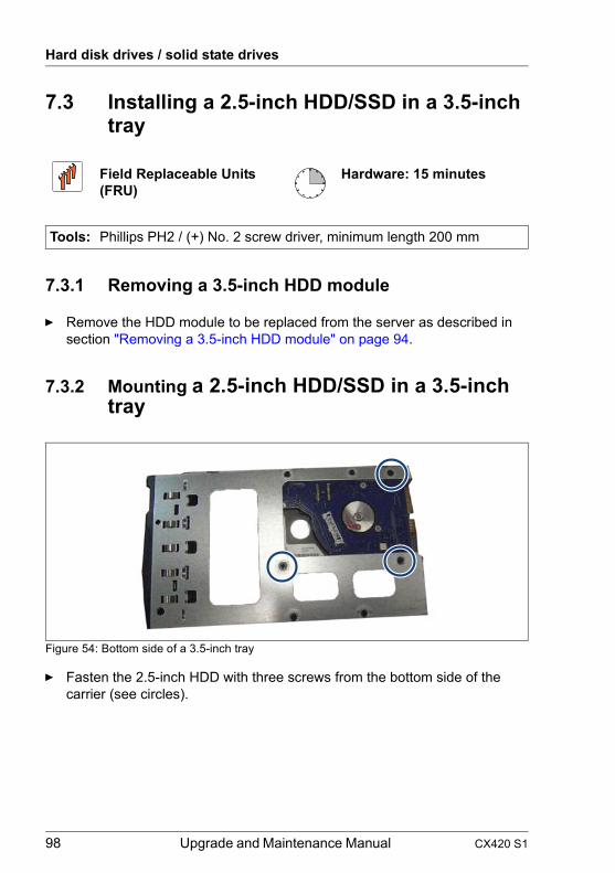
Hard disk drives / solid state drives
7.3 Installing a 2.5-inch HDD/SSD in a 3.5-inch tray
7.3.1 Removing a 3.5-inch HDD module
Ê Remove the HDD module to be replaced from the server as described in section "Removing a 3.5-inch HDD module" on page 94.
7.3.2 Mounting a 2.5-inch HDD/SSD in a 3.5-inch tray
Figure 54: Bottom side of a 3.5-inch tray
Ê Fasten the 2.5-inch HDD with three screws from the bottom side of the carrier (see circles).
Field Replaceable Units (FRU)
Hardware: 15 minutes
Tools: Phillips PH2 / (+) No. 2 screw driver, minimum length 200 mm
98 Upgrade and Maintenance Manual CX420 S1

Hard disk drives / solid state drives
Figure 55: 2.5-inch HDD/SSD assembled in a 3.5-inch tray
7.3.3 Installing the 3.5-inch HDD module
Ê Install the new HDD module into the empty drive bay as described in section "Installing 3.5-inch HDD modules" on page 90.
7.3.4 Concluding steps
Perform the following procedures:
Ê "Performing a RAID array rebuild" on page 66
CX420 S1 Upgrade and Maintenance Manual 99

Hard disk drives / solid state drives
7.4 Replacing HDD/SSD SAS/SATA backplanes
7.4.1 Replacing the 3.5-inch HDD SAS/SATA backplane
Note on system information
The 3.5-inch HDD SAS/SATA backplane contains the Chassis ID EPROM that contains system information like server name and model, housing type, serial number and manufacturing data.
7.4.1.1 Preliminary steps
Perform the following procedures:
Ê "Shutting down the server node" on page 35
Ê "Removing the Dual Node Cluster Server out of the rack" on page 37
V CAUTION!
For ALL service tasks, remove the CX420 S1 Dual Node Cluster Server out of the rack and put it on a separate desk!
It is not allowed to draw the CX420 S1Dual Node Cluster Server partially out of the rack.
Ê "Removing the server node from the Dual Node Cluster Server" on page 42
Ê Remove all HDD modules as described in section "Removing 3.5-inch HDD modules" on page 93.
Ê "Opening the Dual Node Cluster Server" on page 44
Ê "Removing the power supply module" on page 69
Ê Remove both fan modules as described in section "Removing the fan module" on page 117.
Ê "Removing the power distribution module" on page 46
Field Replaceable Units (FRU)
Hardware: 75 minutes
Tools: Phillips PH2 / (+) No. 2 screw driver, minimum length 200 mm
100 Upgrade and Maintenance Manual CX420 S1

Hard disk drives / solid state drives
Ê "Removing the midplane" on page 133
Ê Remove all linking boards as described in section "Removing the linking board" on page 142
7.4.1.2 Removing the 3.5-inch HDD SAS / SATA backplane
Figure 56: Removing the front panel cable from the cable clamps
Ê Remove both front panel cables from the cable clamps.
Figure 57: Removing the HDD SAS/SATA backplane (A)
Ê Note the positions of the shoulder screw caps (1).
Ê Remove two screws (2) of the defective HDD SAS/SATA backplane.
CX420 S1 Upgrade and Maintenance Manual 101

Hard disk drives / solid state drives
Figure 58: Removing the HDD SAS/SATA backplane (B)
Ê Slide the HDD SAS/SATA backplane in the direction of the arrow (1) as far as it will go.
Ê Lift the HDD SAS/SATA backplane out of the chassis (2).
102 Upgrade and Maintenance Manual CX420 S1

Hard disk drives / solid state drives
7.4.1.3 Installing the 3.5-inch HDD SAS/SATA backplane
Figure 59: Installing the HDD SAS/SATA backplane (A)
Ê Note the positions of the shoulder screw caps (1) and the screw holes (2) on the chassis.
Figure 60: Installing the HDD SAS/SATA backplane (B)
Ê Insert the new HDD SAS/SATA backplane into the chassis (1):
– The two shoulder screw caps on the chassis rest in the wide end and the center of the keyhole slots on the HDD SAS/SATA backplane.
– The five noses of the backplane fit behind the guides (see circles).
Ê Slide the HDD SAS/SATA backplane in the direction of the arrow as far as it will go (2).
CX420 S1 Upgrade and Maintenance Manual 103

Hard disk drives / solid state drives
Figure 61: Installing the HDD SAS/SATA backplane (C)
Ê Secure HDD SAS/SATA backplane with two screws (1).
Figure 62: Removing the front panel cable from the cable clamps
Ê Secure both front panel cables with the cable clamps.
7.4.1.4 Concluding steps
Perform the following procedures:
Ê Insert all linking boards as described in section "Installing the linking board" on page 143.
Ê "Installing the midplane" on page 135
Ê "Installing the power distribution module" on page 49
104 Upgrade and Maintenance Manual CX420 S1

Hard disk drives / solid state drives
Ê Install both fan modules as described in section "Installing the fan module" on page 127.
Ê "Installing the power supply module" on page 71
Ê "Closing the Dual Node Cluster Server" on page 53
Ê Install all HDD/SSD modules as described in section "Installing 3.5-inch HDD modules" on page 90.
Ê "Installing the server node in the Dual Node Cluster Server" on page 55
Ê "Mounting the Dual Node Cluster Server in the rack" on page 57
Ê "Switching on the server node(s)" on page 64
Ê "Using the Chassis ID Prom Tool" on page 66
7.5 Configuration and management of virtual disks in storage spaces
Starting with Windows Server 2012 Microsoft implemented a functionality called "Storage Spaces". Compared to solutions based on hardware RAID (based on a RAID controller) Storage Spaces is implemented as part of the base operating system and is not manageable with management tools like ServerView RAID manager.
To configure and manage Storage Spaces the builtin Microsoft tools like Server Manager or PowerShell need to be used. A good overview can be found at:
http://technet.microsoft.com/en-us/library/hh831739.aspx
7.5.1 Error situations
7.5.1.1 Less severe errors
If a less severe error occurs on a physical disk during a write operation to this disk, the physical disk is marked as unhealthy. The corresponding virtual disk is marked unhealthy too and the operational status is set to Degraded:
CX420 S1 Upgrade and Maintenance Manual 105

Hard disk drives / solid state drives
Figure 63: Virtual Disks
Figure 64: Virtual Disk1
If subsequent writes to the physical disk succeed, the physical disk is marked as healthy again, while the virtual disk is still marked as unhealthy, because the data on disks is out of sync.
The virtual disk remains degraded until either a repair operation is started or an automatic re-synchronization occurs, which occurs after a five minute interval.
To force that re-synchronization, please right click on the virtual disk and choose Repair Virtual Disk:
Figure 65: Repair Virtual Disk
The data on disks will now be synced and the operational status is set to In Service:
106 Upgrade and Maintenance Manual CX420 S1

Hard disk drives / solid state drives
Figure 66: Virtual Disk1 - In Service
7.5.1.2 Severe errors
If a severe error occurs on a physical disk Storage Spaces marks the disk as unhealthy:
Figure 67: Virtual Disks - Physical Disks
The virtual disk is then marked as degraded until the failed disk is replaced and a repair operation is started. If a hot spare is present in the storage pool, the hot spare comes online immediately. Depending on the error code the disk drive is returning, Storage Spaces will also illuminate the failure LED for the affected slot (the failure LED is available on PRIMERGY disk enclosures released for Storage Spaces).
To locate the failed physical disk, you can switch on the LED at this disk. You have two possibilities to illuminate the LED:
1. Illuminate the LED via Storage Spaces GUI or
2. Illuminate the LED using PowerShell
The second method is useful, if the failed disk is not visible in File and Storage Services.
CX420 S1 Upgrade and Maintenance Manual 107

Hard disk drives / solid state drives
Illuminating LED via Storage Spaces GUI
Ê Right click the failed physical disk and choose Toggle Drive Light.
Figure 68: Toggle Drive Light
Illuminating LED using PowerShell
If the failed disk is not visible in File and Storage Services for some reason, the only way to illuminate the LED is PowerShell:
While some disks are not listed in File and Storage Services the Cmdlet Get-PhysicalDisk will list all physical disks
Figure 69: PowerShell
If the failed disk is found in the list, the LED can be illuminated by the Cmdlet Enable-PhysicalDiskIndication.
In the above example the command would be this:
Enable-PhysicalDiskIndication -FriendlyName PhysicalDisk4
7.5.2 Disk Error Details
If a physical disk encounters an error, a system eventlog with ID 7 or 11 is recorded in the system eventlog:
Figure 70: System eventlog ID 7
108 Upgrade and Maintenance Manual CX420 S1

Hard disk drives / solid state drives
Figure 71: System eventlog ID 11
The binary details of these event logs list more information about the failure type:
7.5.3 Storage Spaces Event Logging
Further errors logged for Storage Spaces can be found in Event Viewer under:
Applications and Services Logs/Microsoft/Windows/StorageSpaces-Driver/Operational
These logs contain the DiskGUID, which identifies the physical or virtual disk (e.g. 4988b42f-a2a2-11e2-93eb-001999d49f20).
With Cmdlets Get-PhysicalDisk and Get-VirtualDisk the disk can be listed in PowerShell:
– get-physicaldisk |? { $_.ObjectId.Contains( {<GUID>} ); }
– get-virtualdisk |? { $_.ObjectId.Contains( {<GUID>} ); }
7.5.4 Transitional Errors
If Storage Spaces encounters a read error, it will not mark a disk as failed. In a Mirror or Parity configuration, Storage Spaces attempts to retrieve the alternate copy of the data.
In the event that a disk cannot be written to or read from, but never returns an error, Storage Spaces treats the condition as a transitory failure. The action that Storage Spaces takes is configurable and defined by the Set-StoragePool -RetireMissingPhysicalDisks cmdlet; "Auto" is the default:
Offset Description0x92 Sense Code0x9c Additional Sense Code0x9d Additional Sense Code Qualifier
CX420 S1 Upgrade and Maintenance Manual 109

Hard disk drives / solid state drives
7.5.5 Automatic Email Notification
To send an automatic error notification via email to a system administrator or do some other actions if an error occurs on a Storage Spaces disk, you can attach a task to a certain type of eventlog and choose whether to send an email or run a command:
Figure 72: Attach Task To This Event
Option BehaviourEnabled If a disk is missing but its enclosure is still
present, treat the missing disk as failed and retire it.
Disabled If a disk is missing, wait for either the disk to reconnect or for administrative action. GUI will show a status "Lost communication".
Auto If the pool has a hot spare, follow the Enabled logic. Otherwise, follow the Disabled logic.
110 Upgrade and Maintenance Manual CX420 S1

Hard disk drives / solid state drives
Figure 73: Create Basic Task Wizard
With Task Scheduler more triggers can be defined:
Figure 74: New Trigger
CX420 S1 Upgrade and Maintenance Manual 111

Hard disk drives / solid state drives
112 Upgrade and Maintenance Manual CX420 S1

8 System fanSafety instructions
V CAUTION!
● Do not damage or modify internal cables or devices. Doing so may cause a device failure, fire, or electric shock.
● Devices and components inside the server remain hot after shutdown. After shutting down the server, wait for hot components to cool down before installing or removing internal options.
● Circuit boards and soldered parts of internal options are exposed and can be damaged by static electricity. Always discharge static build-up (e.g. by touching a grounded object) before handling electrostatic-sensitive devices (ESDs).
● Do not touch the circuitry on boards or soldered parts. Hold circuit boards by their metallic areas or edges.
● If devices are installed or disassembled using methods other than those outlined in this chapter, the warranty will be invalidated.
● For further information, please refer to chapter "Important information" on page 25.
CX420 S1 Upgrade and Maintenance Manual 113

System fan
8.1 Basic Information
The PRIMERGY CX420 S1 server features four non hot-plug fans. Two fans each are combined in a fan module.
Fan positions
The figure 75 shows the position of the system fans 1 to 4.
Figure 75: Fan positions
114 Upgrade and Maintenance Manual CX420 S1

System fan
Connectors on the PDB
The figure 76 shows the connectors on the PDBs for the system fans 1 to 4.
Figure 76: Connectors on the PDBs
– Fan1 and fan2 are connected to the top PDB.
– Fan3 and fan4 are connected to the bottom PDB.
Top PDB Bottom PDB1 J3 J32 J4 J43 FAN1 (J8) FAN3 (J8)4 FAN2 (J9) FAN4 (J9)
Cable Connector on the PDBFan1-5
C3FAN1 (J8) and J3, top PDB
Fan2-6 FAN2 (J9) and J4, top PDBFan3-7
C3FAN3 (J8) and J3, bottom PDB
Fan4-8 FAN4 (J9) and J4, bottom PDB
Table 5: Fan cabling
top PDB bottom PDB
CX420 S1 Upgrade and Maintenance Manual 115

System fan
8.2 Replacing the fan in the fan module
8.2.1 Preliminary steps
Perform the following procedures:
Ê "Shutting down the server node" on page 35
Ê "Removing the Dual Node Cluster Server out of the rack" on page 37
V CAUTION!
For ALL service tasks, remove the CX420 S1 Dual Node Cluster Server out of the rack and put it on a separate desk!
It is not allowed to draw the CX420 S1Dual Node Cluster Server partially out of the rack.
Ê "Removing the server node from the Dual Node Cluster Server" on page 42
Ê "Opening the Dual Node Cluster Server" on page 44
Field Replaceable Unit(FRU)
Hardware: 20 minutes
Tools: Phillips PH2 / (+) No. 2 screw driver
116 Upgrade and Maintenance Manual CX420 S1

System fan
8.2.2 Removing the fan module
I There are available two different kinds of fan modules:
– fan module without detachable cable– fan module with detachable cable
Follow the appropriate procedure described in the sections "Fan without detachable cable" on page 117 or "Fan with detachable cable" on page 118.
Fan without detachable cable
Figure 77: Removing the fan module (A)
Ê Disconnect the fan cables from the corresponding PDB:
– For fan1 and fan2 from the top PDB (1)
– For fan3 and fan4 from the bottom PDB (2)
Ê Thread the fan cables carefully through the recess (3).
CX420 S1 Upgrade and Maintenance Manual 117

System fan
Fan with detachable cable
Figure 78: Fan with detachable cable
I Fans will now be replaced by fans with detachable cable. There will be no change of product number.
Figure 79: Detachable cable of fan
I Disconnecting the cables from the top PDB and from the bottom PDB is now unnecessary! Just detach the cable from the connector and carefully thread the fan cable through the recess.
118 Upgrade and Maintenance Manual CX420 S1

System fan
Figure 80: Removing the fan module (B)
Ê Remove four screws.
Ê Carefully lift the fan module out of the chassis.
V CAUTION!
Ensure not to strain the fan cables!
Ê Replace the defective fan as described in section "Replacing the fan in the fan module" on page 116.
8.2.3 Removing the fan from the fan holder
I If you want replace fan1, you have to remove fan2 before.
If you want replace fan4, you have to remove fan3 before.
CX420 S1 Upgrade and Maintenance Manual 119

System fan
Figure 81: Removing the fan from the fan holder
Ê Remove four screws.
Ê Remove the fan out of the fan holder (1).
Fan 1
Fan 2
120 Upgrade and Maintenance Manual CX420 S1

System fan
8.2.4 Installing fan1 and fan2
Figure 82: Air flow direction
I Take note of the air flow direction.
CX420 S1 Upgrade and Maintenance Manual 121

System fan
8.2.4.1 Installing the fan1
Figure 83: Installing fan1 in the fan holder
Ê Insert fan1 in the left part of the fan holder (1).
I Take note of the air flow direction (2).
Ê Run the fan cable along the bottom of the fan holder (3).
Ê Pull the fan cable through the recess on the right side (4).
Ê Secure the fan with four screws.
air flow
122 Upgrade and Maintenance Manual CX420 S1

System fan
8.2.4.2 Installing the fan2
Figure 84: Installing fan2 in the fan holder
Ê Insert fan2 in the right part of the fan holder (1).
I Take note of the air flow direction (2).
Ê Pull the fan1 cable to ensure not to be interfered with fan2 (3).
Ê Secure the fan with four screws.
air flow
CX420 S1 Upgrade and Maintenance Manual 123

System fan
8.2.5 Installing fan3 and fan4
Figure 85: Air flow direction
I Take note of the air flow direction.
124 Upgrade and Maintenance Manual CX420 S1

System fan
8.2.5.1 Installing the fan4
Figure 86: Installing fan4 in the fan holder
Ê Insert fan4 in the right part of the fan holder (1).
I Take note of the air flow direction (2).
Ê Run the fan cable along the bottom of the fan holder (3).
Ê Pull the fan cable through the recess on the left side (4).
Ê Secure the fan with four screws.
air flow
CX420 S1 Upgrade and Maintenance Manual 125

System fan
8.2.5.2 Installing the fan3
Figure 87: Installing fan3 in the fan holder
Ê Insert fan3 in the left part of the fan holder (1).
I Take note of the air flow direction (2).
Ê Pull the fan4 cable to ensure not to be interfered with fan3 (3).
Ê Secure the fan with four screws.
air flow
126 Upgrade and Maintenance Manual CX420 S1

System fan
8.2.6 Installing the fan module
I There are available two different kinds of fan modules:
– fan module without detachable cable– fan module with detachable cable
Follow the appropriate procedure described in the sections "Fan module without detachable cable" on page 128 or "Fan with detachable cable" on page 128.
Figure 88: Installing the fan module
Ê Insert the fan module into its slot.
Ê Ensure that the fan module is properly seated in the chassis.
Ê Secure each fan module with four screws.
Fan1-5 Fan2-6 Fan3-7 Fan4-8
CX420 S1 Upgrade and Maintenance Manual 127

System fan
Fan module without detachable cable
Figure 89: Removing the fan module (A)
Ê Thread the fan cables carefully through the recess (1).
Ê Connect the fan cables to the corresponding PDB, see also "Basic Information" on page 114:
– For fan1 and fan2 to the top PDB (2)
– For fan3 and fan4 to the bottom PDB (3)
Fan with detachable cable
Figure 90: Fan with detachable cable
128 Upgrade and Maintenance Manual CX420 S1

System fan
I Fans will now be replaced by fans with detachable cable. There will be no change of product number.
Figure 91: Detachable cable of fan
I Connecting the cables to the top PDB and to the bottom PDB is now unnecessary! Carefully thread the fan cable through the recess and connect the cable to the connector.
8.2.7 Concluding steps
Perform the following procedures:
Ê "Closing the Dual Node Cluster Server" on page 53
Ê "Installing the server node in the Dual Node Cluster Server" on page 55
Ê "Mounting the Dual Node Cluster Server in the rack" on page 57
Ê "Switching on the server node(s)" on page 64
CX420 S1 Upgrade and Maintenance Manual 129

System fan
130 Upgrade and Maintenance Manual CX420 S1

9 MidplaneSafety instructions
V CAUTION!
● Do not damage or modify internal cables or devices. Doing so may cause a device failure, fire, or electric shock.
● Devices and components inside the server remain hot after shutdown. After shutting down the server, wait for hot components to cool down before installing or removing internal options.
● Circuit boards and soldered parts of internal options are exposed and can be damaged by static electricity. Always discharge static build-up (e.g. by touching a grounded object) before handling electrostatic-sensitive devices (ESDs).
● Do not touch the circuitry on boards or soldered parts. Hold circuit boards by their metallic areas or edges.
● If devices are installed or disassembled using methods other than those outlined in this chapter, the warranty will be invalidated.
● For further information, please refer to chapter "Important information" on page 25.
CX420 S1 Upgrade and Maintenance Manual 131

Midplane
9.1 Replacing the midplane
9.1.1 Preliminary steps
Perform the following procedures:
Ê "Shutting down the server node" on page 35
Ê "Removing the Dual Node Cluster Server out of the rack" on page 37
V CAUTION!
For ALL service tasks, remove the CX420 S1 Dual Node Cluster Server out of the rack and put it on a separate desk!
It is not allowed to draw the CX420 S1Dual Node Cluster Server partially out of the rack.
Ê "Removing the server node from the Dual Node Cluster Server" on page 42
Ê "Opening the Dual Node Cluster Server" on page 44
Ê "Removing the power supply module" on page 69
Ê "Removing the power distribution module" on page 46
Field Replaceable Unit(FRU)
Hardware: 45 minutes
Tools: Phillips PH2 / (+) No. 2 screw driver
132 Upgrade and Maintenance Manual CX420 S1

Midplane
9.1.2 Removing the midplane
Figure 92: Removing the air duct
Ê Detach the right and the left side of the adhesive air duct by pressing it inwards (1).
Ê Remove the air duct in the direction of the arrow (2).
CX420 S1 Upgrade and Maintenance Manual 133

Midplane
Figure 93: Disconnecting the front panel cable
Ê Disconnect both front panel cables from the rear of the midplane.
Figure 94: Removing the midplane
Ê Remove ten screws from the midplane (see circles).
Ê Remove the midplane (1).
134 Upgrade and Maintenance Manual CX420 S1

Midplane
9.1.3 Installing the midplane
Figure 95: Positions of the centering bolts
Ê Note of the positions of the centering bolts in the chassis.
Figure 96: Mounting the midplane (A)
Ê Insert the midplane (1) onto the centering bolts (2).Ensure that the midplane is properly seated on both centering bolts.
Ê Ensure that the linking boards are properly connected with the connectors on the midplane.
CX420 S1 Upgrade and Maintenance Manual 135

Midplane
Figure 97: Mounting the midplane (B)
Ê Secure the midplane with ten screws (see circles).
Figure 98: Connecting the front panel cables
Ê Connect the right front panel cable to the right connector on the rear of the midplane (1).
Ê Connect the left front panel cable to the left connector on the rear of the midplane (2).
136 Upgrade and Maintenance Manual CX420 S1

Midplane
Figure 99: Midplane air duct
Ê Note the direction of the air duct.
Figure 100: Installing the air duct
Ê Insert the air duct in the direction of the arrow (1).
Ê Attach the right and the left side of the air duct to the adhesive tapes on the chassis by pressing it outwards (2).
CX420 S1 Upgrade and Maintenance Manual 137

Midplane
9.1.4 Concluding steps
Perform the following procedures:
Ê "Installing the power distribution module" on page 49
Ê "Installing the power supply module" on page 71
Ê "Closing the Dual Node Cluster Server" on page 53
Ê "Installing the server node in the Dual Node Cluster Server" on page 55
Ê "Mounting the Dual Node Cluster Server in the rack" on page 57
Ê "Switching on the server node(s)" on page 64
138 Upgrade and Maintenance Manual CX420 S1

10 Linking boardsSafety
V CAUTION!
● Do not damage or modify internal cables or devices. Doing so may cause a device failure, fire, or electric shock.
● Devices and components inside the server remain hot after shutdown. After shutting down the server, wait for hot components to cool down before installing or removing internal options.
● Circuit boards and soldered parts of internal options are exposed and can be damaged by static electricity. Always discharge static build-up (e.g. by touching a grounded object) before handling electrostatic-sensitive devices (ESDs).
● Do not touch the circuitry on boards or soldered parts. Hold circuit boards by their metallic areas or edges.
● If devices are installed or disassembled using methods other than those outlined in this chapter, the warranty will be invalidated.
● For further information, please refer to chapter "Important information" on page 25.
CX420 S1 Upgrade and Maintenance Manual 139

Linking boards
10.1 Linking boards in 3.5-inch HDD chassis
10.1.1 Basic information
The chassis for 3.5" HDD is equipped with four different linking boards.
Figure 101: Positions of the linking boards chassis 3.5" HDD
Pos. Description Part number1 Linking/B-1 A3C40160715 31S2HLB00402 Linking/B-2 A3C40160716 31S2HLB00503 Linking/B-3 A3C40160718 31S2HLB00604 Linking/B-4 A3C40160719 31S2HLB0070
140 Upgrade and Maintenance Manual CX420 S1

Linking boards
10.1.2 Replacing the linking board
10.1.2.1 Preliminary steps
Perform the following procedures:
Ê "Shutting down the server node" on page 35
Ê "Removing the Dual Node Cluster Server out of the rack" on page 37
V CAUTION!
For ALL service tasks, remove the CX420 S1 Dual Node Cluster Server out of the rack and put it on a separate desk!
It is not allowed to draw the CX420 S1Dual Node Cluster Server partially out of the rack.
Ê "Removing the server node from the Dual Node Cluster Server" on page 42
Ê "Opening the Dual Node Cluster Server" on page 44
Ê "Removing the power supply module" on page 69
Ê Remove both fan modules as described in section "Removing the fan module" on page 117.
Ê "Removing the power distribution module" on page 46
Ê "Removing the midplane" on page 133
Field Replaceable Unit(FRU)
Hardware: 55 minutes
Tools: Phillips PH2 / (+) No. 2 screw driver
CX420 S1 Upgrade and Maintenance Manual 141

Linking boards
10.1.2.2 Removing the linking board
Figure 102: Removing the linking board
Ê Slide the linking board in the direction of the arrow as far as it will go (1).The linking board will be disconnected from the HDD backplane (2).
Ê Lift the linking board out of the chassis (3).
142 Upgrade and Maintenance Manual CX420 S1

Linking boards
10.1.2.3 Installing the linking board
Figure 103: Board number and mounting direction of the linking board
Ê Note the board number (1) and the mounting direction (2) of the linking board.
Figure 104: Positions of the shoulder screw caps on the chassis
Ê Note the positions of the shoulder screw caps on the chassis.
CX420 S1 Upgrade and Maintenance Manual 143

Linking boards
Figure 105: Installing the linking board (A)
Ê Insert the linking board into the chassis so that the two shoulder screw caps on the chassis rest in the wide ends of the keyhole slots on the linking board.
Figure 106: Installing the linking board (B)
Ê Slide the linking board in the direction of the arrow as far as it will go (1).The linking board will be connected to the HDD backplane (2).
144 Upgrade and Maintenance Manual CX420 S1

Linking boards
10.1.2.4 Concluding steps
Perform the following procedures:
Ê "Installing the midplane" on page 135
Ê "Installing the power distribution module" on page 49
Ê Install both fan modules as described in section "Installing the fan module" on page 127.
Ê "Installing the power supply module" on page 71
Ê "Closing the Dual Node Cluster Server" on page 53
Ê "Installing the server node in the Dual Node Cluster Server" on page 55
Ê "Mounting the Dual Node Cluster Server in the rack" on page 57
Ê "Switching on the server node(s)" on page 64
CX420 S1 Upgrade and Maintenance Manual 145

Linking boards
146 Upgrade and Maintenance Manual CX420 S1

11 Front panel Safety instructions
V CAUTION!
● When inserting the front panel module into the server, ensure not to pinch or strain any connected cables.
● Circuit boards and soldered parts of internal options are exposed and can be damaged by static electricity. Always discharge static build-up (e.g. by touching a grounded object) before handling electrostatic-sensitive devices (ESDs)
● Do not touch the circuitry on boards or soldered parts. Hold circuit boards by their metallic areas or edges.
● For further information, please refer to chapter "Important information" on page 25.
CX420 S1 Upgrade and Maintenance Manual 147

Front panel
11.1 Replacing the front panel board
11.1.1 Preliminary steps
Perform the following procedures:
Ê "Shutting down the server node" on page 35
Ê "Removing the Dual Node Cluster Server out of the rack" on page 37
V CAUTION!
For ALL service tasks, remove the CX420 S1 Dual Node Cluster Server out of the rack and put it on a separate desk!
It is not allowed to draw the CX420 S1Dual Node Cluster Server partially out of the rack.
Field Replaceable Unit(FRU)
Hardware: 10 minutes
Tools: Phillips PH2 / (+) No. 2 screw driver
148 Upgrade and Maintenance Manual CX420 S1

Front panel
11.1.2 Removing the front ear bracket
Figure 107: Removing the front ear bracket
Ê Remove the feature (1) under the bezel hook.
Ê Remove the metal sheet by removing the two screws (2).
Figure 108: Spacer (metal sheet)
CX420 S1 Upgrade and Maintenance Manual 149

Front panel
11.1.3 Removing the front panel board
Figure 109: Removing the front panel cover (A)
Ê Remove the screw if there is no front ear bracket (see section "Removing the front ear bracket" on page 149).
150 Upgrade and Maintenance Manual CX420 S1

Front panel
Figure 110: Removing the front panel cover (B)
Ê Remove the front panel cover.
CX420 S1 Upgrade and Maintenance Manual 151

Front panel
Figure 111: Removing the front panel board
Ê Remove the screw (1) and disengage the front panel board (2).
Figure 112: Disconnecting the front panel cable
Ê Disconnect the front panel cable from the front panel module.
152 Upgrade and Maintenance Manual CX420 S1

Front panel
11.1.4 Installing the front panel board
Figure 113: Connecting the front panel cable - left side
Ê Connect the front panel cable to the front panel module as shown.
Figure 114: Connecting the front panel cable - right side
CX420 S1 Upgrade and Maintenance Manual 153

Front panel
Ê On the right side, fold the cable in the direction of the arrow.
Figure 115: Installing the front panel board
Ê Place the front panel board: The recess on the top will be secured with the screw (1) and the hook on the bottom must fit with the recess (2).
V CAUTION!
Ensure that none of the cables are strained or damaged!
Ê Ensure that the four small button covers are properly seated.
154 Upgrade and Maintenance Manual CX420 S1

Front panel
Figure 116: Installing the front panel cover (A)
Ê Install the front panel cover.
CX420 S1 Upgrade and Maintenance Manual 155

Front panel
Figure 117: Installing the front panel cover (B)
Ê Secure the front panel cover with one screw if there is no front ear bracket (see section"Installing the front ear bracket" on page 157).
156 Upgrade and Maintenance Manual CX420 S1

Front panel
11.1.5 Installing the front ear bracket
Figure 118: Installing the front ear bracket
Ê Insert the feature (1) under the bezel hook to prevent bezel peer off.
Ê Fix the metal sheet with the two screws (2).
Figure 119: Spacer (metal sheet)
CX420 S1 Upgrade and Maintenance Manual 157

Front panel
11.1.6 Concluding steps
Perform the following procedures:
Ê "Mounting the Dual Node Cluster Server in the rack" on page 57
Ê "Switching on the server node(s)" on page 64
158 Upgrade and Maintenance Manual CX420 S1
Front panel
11.2 Replacing the front panel cable
11.2.1 Preliminary steps
Perform the following procedures:
Ê "Shutting down the server node" on page 35
Ê "Removing the Dual Node Cluster Server out of the rack" on page 37
V CAUTION!
For ALL service tasks, remove the CX420 S1 Dual Node Cluster Server out of the rack and put it on a separate desk!
It is not allowed to draw the CX420 S1Dual Node Cluster Server partially out of the rack.
Ê "Removing the server node from the Dual Node Cluster Server" on page 42
Ê Remove all HDD modules as described in section "Removing 3.5-inch HDD modules" on page 93 (if applicable)
Ê "Opening the Dual Node Cluster Server" on page 44
Ê "Removing the power supply module" on page 69
Ê Remove both fan modules as described in section "Removing the fan module" on page 117.
Ê "Removing the power distribution module" on page 46
Ê "Removing the midplane" on page 133
Ê Remove all linking boards for 3.5-inch HDD as described in section "Removing the linking board" on page 142 (if applicable).
Ê "Removing the 3.5-inch HDD SAS / SATA backplane" on page 101 (if applicable)
Ê "Removing the front panel board" on page 150
Field Replaceable Unit(FRU)
Hardware: 20 minutes
Tools: Phillips PH2 / (+) No. 2 screw driver
CX420 S1 Upgrade and Maintenance Manual 159

Front panel
11.2.2 Removing the front panel cable
Figure 120: Removing the front panel cable
Ê Slide the front panel cable over the standoffs (1, 2) to remove the front panel cable.
V CAUTION!
Ensure that none of the cables are strained or damaged!
160 Upgrade and Maintenance Manual CX420 S1

Front panel
11.2.3 Installing the front panel cable
Figure 121: Installing front panel cable (A)
Ê Use a thin cable noose (thickness under 1.0 mm) to route the front panel cable.
Figure 122: Installing front panel cable (B)
Ê Insert the cable (1), while following the cable routing. The cable must be run over the standoff (2) and then under the standoff (3).
CX420 S1 Upgrade and Maintenance Manual 161

Front panel
11.2.4 Routing of the front panel cable
Figure 123: Routing of the front panel cable
11.2.5 Concluding steps
Perform the following procedures:
Ê "Installing the front panel board" on page 153
Ê "Installing the 3.5-inch HDD SAS/SATA backplane" on page 103 (if applicable)
Ê Install all linking boards for 3.5-inch HDD as described in section "Installing the linking board" on page 143 (if applicable).
Ê "Installing the midplane" on page 135
Ê "Installing the power distribution module" on page 49
Ê "Installing the power supply module" on page 71
Ê Install both fan modules as described in section "Installing the fan module" on page 127.
Ê "Closing the Dual Node Cluster Server" on page 53
162 Upgrade and Maintenance Manual CX420 S1

Front panel
Ê Install all HDD modules as described in section "Installing 3.5-inch HDD modules" on page 90 (if applicable)
Ê "Installing the server node in the Dual Node Cluster Server" on page 55
Ê "Mounting the Dual Node Cluster Server in the rack" on page 57
Ê "Switching on the server node(s)" on page 64
CX420 S1 Upgrade and Maintenance Manual 163

Front panel
164 Upgrade and Maintenance Manual CX420 S1

12 CablingSafety instructions
V CAUTION!
● Always hold cables by their connectors when disconnecting them. Never pull on the cable to disconnect cables.
● Ensure that none of the cables are scraped, strained or otherwise damaged while replacing system components.
● Immediately replace cables with damaged shielding.
● Always use shielded network cables.
12.1 Cabling overview
I The part number of the cables can be the first or the second one.
* (C3): There are two possible types of this cable (see also chapter "Fan with detachable cable" on page 118):
– without detachable cable: Two connectors for top/bottom PDB are connected to the cable of the fan directly.
No. Part number Type DescriptionC1 DD0S2HPB201 Power from HDD BP to top PDBC2 DD0S2HPB501 Power from HDD BP to bottom PDBC3 DQ5DC88P003 Fan cable from fan to top/bottom PDB *C4 DD0S2HTH501 I2C from midplane to top/bottom PDBC5 DD0S2HTH000 Front panel from front panel to MidplaneC6 DD0S2HPB401 Power from midplane to top PDB C7 DD0S2HPB301 Power from midplane to bottom PDBC8 DD0S2HPB701 Power from HDD BP to top PDBC9 DD0S2LTH800 Power from HDD BP to top PDB
Table 6: List of used cables
CX420 S1 Upgrade and Maintenance Manual 165

Cabling
– with detachable cable: Cable with two connectors for top/bottom PDB is detachable from the fan.
12.2 Connectors on the boards
Figure 124: Top PDB
1 J32 J43 FAN1 (J8)4 FAN2 (J9)5 J26 MB1_PWR_CONN7 MB2_PWR_CONN8 BP PWR CONN
166 Upgrade and Maintenance Manual CX420 S1

Cabling
Figure 125: Bottom PDB
1 J32 J43 FAN3 (J8)4 FAN4 (J9)5 J26 MB3_PWR_CONN7 MB4_PWR_CONN8 BP PWR CONN9 J10 - connector for the Top PDB
CX420 S1 Upgrade and Maintenance Manual 167

Cabling
Figure 126: Midplane
1 Expander board of Node 22 Expander board of Node 23 Expander board of Node 14 Expander board of Node 15 MB26 J167 J148 MB1
168 Upgrade and Maintenance Manual CX420 S1

Cabling
12.3 Cabling
Figure 127: 3.5-inch chassis
CX420 S1 Upgrade and Maintenance Manual 169

Cabling
170 Upgrade and Maintenance Manual CX420 S1

13 Appendix
13.1 Mechanical overview
13.1.1 Multi-node server system front 3.5 inch HDD model
Figure 128: PRIMERGY CX420 S1 front - 3.5-inch HDD model
With CX272 S1 server nodes
Pos. Component1 Front panel module for server node 12 Front panel module for server node 23 12 x 3.5" / 2.5" hard disk trays
CX420 S1 Upgrade and Maintenance Manual 171

Appendix
13.1.2 Multi-node server system rear
13.1.2.1 CX420 S1 Dual Node Cluster Server with CX272 S1 server nodes
Figure 129: PRIMERGY CX420 S1 Dual Node Cluster Server rear with CX272 S1 server nodes
Pos. Component1 Installation bay 1 for CX272 S1 server nodes2 Installation bay 2 for CX272 S1 server nodes3 Installation bay 1 for PSU4 Installation bay 2 for PSU
172 Upgrade and Maintenance Manual CX420 S1

Appendix
13.1.3 Multi-node server system interior
13.1.3.1 3.5-inch HDD model
Figure 130: PRIMERGY CX420 S1 interior - 3.5-inch HDD model
Pos. Component1 12 x 3.5" / 2.5" hard disk trays2 2 front panel modules3 HDD backplane (not visible)4 2 fan modules5 midplane6 2x CX272 S17 Power distribution module8 2 power supply modules
CX420 S1 Upgrade and Maintenance Manual 173

Appendix
13.2 Controls and indicators
13.2.1 Front panel
Figure 131: Controls and indicators on the front panel
Pos. Component1 On/Off button / Power-on indicator2 ID button / ID indicator
174 Upgrade and Maintenance Manual CX420 S1
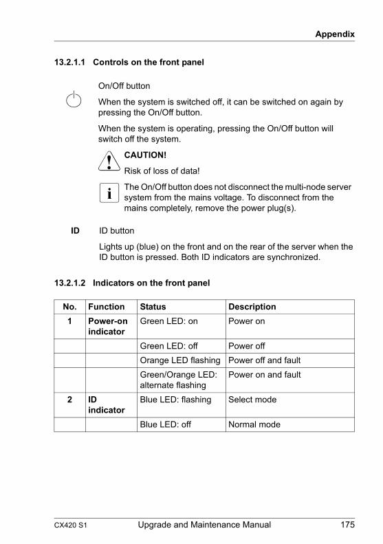
Appendix
13.2.1.1 Controls on the front panel
13.2.1.2 Indicators on the front panel
On/Off button
When the system is switched off, it can be switched on again by pressing the On/Off button.
When the system is operating, pressing the On/Off button will switch off the system.
V CAUTION!
Risk of loss of data!
I The On/Off button does not disconnect the multi-node server system from the mains voltage. To disconnect from the mains completely, remove the power plug(s).
ID ID button
Lights up (blue) on the front and on the rear of the server when the ID button is pressed. Both ID indicators are synchronized.
No. Function Status Description1 Power-on
indicator Green LED: on Power on
Green LED: off Power offOrange LED flashing Power off and faultGreen/Orange LED: alternate flashing
Power on and fault
2 ID indicator
Blue LED: flashing Select mode
Blue LED: off Normal mode
CX420 S1 Upgrade and Maintenance Manual 175

Appendix
13.2.2 Hard disk drives
13.2.2.1 Indicators on the hard disk drives
Figure 132: Indicators on the 3.5-inch HDD modules (A)
1 Slot/RAID status indicator
– Does not light: HDD/SSD does not exist– Lit (green): HDD/SSD exist– Lit (red): HDD/SSD Faulty (drive defective, needs replacing)– Flashing (orange/red): HDD/SSD Rebuild (the data is being restored
after changing a drive)– Lit (orange): HDD/SSD Identify
2 HDD/SSD activity indicator (green)
– Lit: HDD/SSD in active phase (drive active, drive being accessed)– Does not light: HDD/SSD inactive
176 Upgrade and Maintenance Manual CX420 S1

Appendix
13.2.3 Power supply module
13.2.3.1 Indicator on hot-plug power supply module
Figure 133: Indicator on hot-plug PSU
13.2.4 Server nodes
I The controls and indicators of the server nodes are described in the corresponding Operating or Upgrade and Maintenance manuals, see "Documents for the server nodes" on page 23.
1 Indicator on hot-plug PSU (two colors)
1200 W PSU:
Lights up green when the Dual Node Cluster Server is switched on and functioning properly.
Lights up yellow if the PSU has failed.
CX420 S1 Upgrade and Maintenance Manual 177

Appendix
13.3 Minimum startup configuration
If the server does not start up or other problems occur, it may be necessary to take the system down to its most basic configuration in order to isolate the defective component.
The minimum startup configuration consists of the following components and cables:
Ê Shut down the server as described in section "Shutting down the server node" on page 35.
Ê Remove the AC power cord from the cable tie and disconnect it from the system as described in section "Disconnecting the power cord" on page 36.
Ê Take the system down to its minimum startup configuration.
Ê Reconnect the AC power cord to the power supply module and secure it with a cable tie as described in section "Connecting the power cord" on page 62.
Field Replaceable Units (FRU)
Component Notes and reference2 Server node CX272 S12 PSU
Table 7: Minimum startup configuration - components
Cable Notes and referencePower cable
Table 8: Minimum startup configuration - cables
178 Upgrade and Maintenance Manual CX420 S1

Appendix
Ê Switch on the server as described in section "Switching on the server node(s)" on page 64.
V CAUTION!
Since the fan module is not included in the minimum startup configuration, the server must be shut down immediately after the diagnostic process is complete (POST phase has been passed).
The minimum startup configuration must be used exclusively for diagnostic purposes by maintenance personnel, never in daily operation!
CX420 S1 Upgrade and Maintenance Manual 179

Appendix
180 Upgrade and Maintenance Manual CX420 S1