PRIMERGY BX900 S2 System Unit - Fujitsumanuals.ts.fujitsu.com/file/10660/bx900s2-umm-en.pdf ·...
206
Upgrade and Maintenance Manual - English PRIMERGY BX900 S2 System Unit Upgrade and Maintenance Manual December 2012
Transcript of PRIMERGY BX900 S2 System Unit - Fujitsumanuals.ts.fujitsu.com/file/10660/bx900s2-umm-en.pdf ·...

Upgrade and Maintenance Manual - English
PRIMERGY BX900 S2 System Unit Upgrade and Maintenance Manual
December 2012

Copyright and Trademarks
Comments… Suggestions… Corrections…The User Documentation Department would like toknow your opinion of this manual. Your feedback helpsus optimize our documentation to suit your individual needs.
Feel free to send us your comments by e-mail to [email protected].
Certified documentation according to DIN EN ISO 9001:2008To ensure a consistently high quality standard anduser-friendliness, this documentation was created tomeet the regulations of a quality management system which complies with the requirements of the standardDIN EN ISO 9001:2008.
cognitas. Gesellschaft für Technik-Dokumentation mbHwww.cognitas.de
© c
ogni
tas.
Ges
ells
chft
für T
echn
ik-D
okum
enta
tion
mbH
201
2 P
fad:
C:\P
rogr
amm
e\FC
T\tim
_app
\tim
_loc
al\w
ork\
WA
LTE
R\O
BJ_
DO
KU
-136
48-0
01.fm
Copyright 2012 FUJITSU LIMITED
All rights reserved.Delivery subject to availability; right of technical modifications reserved.
All hardware and software names used are trademarks of their respective manufacturers.
– The contents of this manual may be revised without prior notice.
– Fujitsu assumes no liability for damages to third party copyrights or other rights arising fromthe use of any information in this manual.
– No part of this manual may be reproduced in any form without the prior written permissionof Fujitsu.
Microsoft, Windows, Windows Server, and Hyper V are trademarks or registered trademarks of Microsoft Corporation in the USA and other countries.
Intel and Xeon are trademarks or registered trademarks of Intel Corporation or its subsidiaries in the USA and other countries.

Before reading this manual
For your safety
This manual contains important information for safely and correctly using this product.
Carefully read the manual before using this product. Pay particular attention to the accompanying manual "Safety Notes and Regulations" and ensure these safety notes are understood before using the product. Keep this manual and the manual "Safety Notes and Regulations" in a safe place for easy reference while using this product.
Radio interference
This product is a "Class A" ITE (Information Technology Equipment). In a domestic environment this product may cause radio interference, in which case the user may be required to take appropriate measures. VCCI-A
Aluminum electrolytic capacitors
The aluminum electrolytic capacitors used in the product's printed circuit board assemblies and in the mouse and keyboard are limited-life components. Use of these components beyond their operating life may result in electrolyte leakage or depletion, potentially causing emission of foul odor or smoke.
As a guideline, in a normal office environment (25°C) operating life is not expected to be reached within the maintenance support period (5 years). However, operating life may be reached more quickly if, for example, the product is used in a hot environment. The customer shall bear the cost of replacing replaceable components which have exceeded their operating life. Note that these are only guidelines, and do not constitute a guarantee of trouble-free operation during the maintenance support period.
High safety use
This product has been designed and manufactured to be used in commercial and/or industrial areas as a server.
When used as visual display workplace, it must not be placed in the direct field of view to avoid incommoding reflections (applies only to TX server systems).
The device has not been designed or manufactured for uses which demand an extremely high level of safety and carry a direct and serious risk of life or body if such safety cannot be assured.
BX900 S2 Upgrade and Maintenance Manual

© c
ogni
tas.
Ges
ells
chft
für T
echn
ik-D
okum
enta
tion
mbH
201
2 P
fad:
C:\P
rogr
amm
e\FC
T\tim
_app
\tim
_loc
al\w
ork\
WA
LTE
R\O
BJ_
DO
KU
-136
48-0
01.fm
These uses include control of nuclear reactions in nuclear power plants, automatic airplane flight control, air traffic control, traffic control in mass transport systems, medical devices for life support, and missile guidance control in weapons systems (hereafter, "high safety use"). Customers should not use this product for high safety use unless measures are in place for ensuring the level of safety demanded of such use. Please consult the sales staff of Fujitsu if intending to use this product for high safety use.
Measures against momentary voltage drop
This product may be affected by a momentary voltage drop in the power supply caused by lightning. To prevent a momentary voltage drop, use of an AC uninterruptible power supply is recommended.
(This notice follows the guidelines of Voltage Dip Immunity of Personal Computer issued by JEITA, the Japan Electronics and Information Technology Industries Association.)
Technology controlled by the Foreign Exchange and Foreign Trade Control Law of Japan
Documents produced by Fujitsu may contain technology controlled by the Foreign Exchange and Foreign Trade Control Law of Japan. Documents which contain such technology should not be exported from Japan or transferred to non-residents of Japan without first obtaining authorization in accordance with the above law.
Harmonic Current Standards
This product conforms to harmonic current standard JIS C 61000-3-2.
Only for the Japanese market: About SATA hard disk drives
The SATA version of this server supports hard disk drives with SATA / BC-SATA storage interfaces. Please note that the usage and operation conditions differ depending on the type of hard disk drive used.
Please refer to the following internet address for further information on the usage and operation conditions of each available type of hard disk drive:
http://jp.fujitsu.com/platform/server/primergy/harddisk/
Upgrade and Maintenance Manual BX900 S2

Only for the Japanese market:
I Although described in this manual, some sections do not apply to the Japanese market. These options and routines include:
– CSS (Customer Self Service)
BX900 S2 Upgrade and Maintenance Manual

© c
ogni
tas.
Ges
ells
chft
für T
echn
ik-D
okum
enta
tion
mbH
201
2 P
fad:
C:\P
rogr
amm
e\FC
T\tim
_app
\tim
_loc
al\w
ork\
WA
LTE
R\O
BJ_
DO
KU
-136
48-0
01.fm
Upgrade and Maintenance Manual BX900 S2

Contents
1 Introduction . . . . . . . . . . . . . . . . . . . . . . . . . . . 17
1.1 Where to find which information? . . . . . . . . . . . . . . . 18
1.2 Notational conventions . . . . . . . . . . . . . . . . . . . . 19
2 Before you start . . . . . . . . . . . . . . . . . . . . . . . . 21
2.1 Classification of procedures . . . . . . . . . . . . . . . . . 222.1.1 Customer Replaceable Units (CRU) . . . . . . . . . . . . . . . 222.1.2 Upgrade and Repair Units (URU) . . . . . . . . . . . . . . . . 232.1.3 Field Replaceable Units (FRU) . . . . . . . . . . . . . . . . . 24
2.2 Average task duration . . . . . . . . . . . . . . . . . . . . . 24
2.3 Tools you need at hand . . . . . . . . . . . . . . . . . . . . 25
2.4 Documents you need at hand . . . . . . . . . . . . . . . . . 27
3 Important information . . . . . . . . . . . . . . . . . . . . . 29
3.1 Safety instructions . . . . . . . . . . . . . . . . . . . . . . . 29
3.2 CE conformity . . . . . . . . . . . . . . . . . . . . . . . . . 38
3.3 FCC Class A Compliance Statement . . . . . . . . . . . . . 39
3.4 Environmental protection . . . . . . . . . . . . . . . . . . . 40
4 Basic hardware procedures . . . . . . . . . . . . . . . . . . 43
4.1 Using diagnostics information . . . . . . . . . . . . . . . . 434.1.1 Accessing the management blade web interface . . . . . . . . 444.1.2 Locating the defective system unit . . . . . . . . . . . . . . . . 454.1.3 Determining the error class . . . . . . . . . . . . . . . . . . . 454.1.3.1 Global Error indicator . . . . . . . . . . . . . . . . . . . . 474.1.3.2 Customer Self Service (CSS) indicator . . . . . . . . . . . 474.1.4 Locating the defective component . . . . . . . . . . . . . . . . 48
4.2 Opening the rack door . . . . . . . . . . . . . . . . . . . . . 48
BX900 S2 Upgrade and Maintenance Manual

Contents
© c
ogni
tas.
Ges
ells
chft
für T
echn
ik-D
okum
enta
tion
mbH
201
1 P
fad:
C:\P
rogr
amm
e\FC
T\tim
_app
\tim
_loc
al\w
ork\
WA
LTE
R\O
BJ_
DO
KU
-136
49-0
01.fm
4.3 Shutting down the system unit . . . . . . . . . . . . . . . . . 49
4.4 Connecting the system unit to the mains . . . . . . . . . . . 50
4.5 Switching on the system unit . . . . . . . . . . . . . . . . . . 52
4.6 Removing / installing server blades and storage blades . . . 544.6.1 Installing a single height / single width blade . . . . . . . . . . . 554.6.2 Installing a single height / double width Blade . . . . . . . . . . 574.6.3 Installing a dummy server blade module . . . . . . . . . . . . . 59
4.7 Concluding software tasks . . . . . . . . . . . . . . . . . . . 60
4.8 Closing the rack door . . . . . . . . . . . . . . . . . . . . . . 60
5 Basic software procedures . . . . . . . . . . . . . . . . . . . 63
5.1 Starting the maintenance task . . . . . . . . . . . . . . . . . 635.1.1 Switching on the ID indicator . . . . . . . . . . . . . . . . . . . 635.1.2 Saving / Restoring management blade settings . . . . . . . . . 64
5.2 Completing the maintenance task . . . . . . . . . . . . . . . 665.2.1 Updating / recovering the management blade firmware . . . . . 665.2.1.1 Looking up the management blade firmware version . . . . . 665.2.1.2 Updating the management blade firmware via
management blade web interface . . . . . . . . . . . . . . . 675.2.1.3 Updating the management blade firmware via recovery flash 685.2.2 Verifying the management blade time settings . . . . . . . . . . 705.2.3 Viewing and clearing the System Event Log (SEL) . . . . . . . . 715.2.3.1 Viewing the SEL . . . . . . . . . . . . . . . . . . . . . . . . 715.2.3.2 Clearing the SEL . . . . . . . . . . . . . . . . . . . . . . . 725.2.4 Checking management master/slave behavior . . . . . . . . . 735.2.5 Updating the connection blade firmware . . . . . . . . . . . . . 745.2.6 Configuring connection blade settings . . . . . . . . . . . . . . 755.2.7 Saving connection blade settings . . . . . . . . . . . . . . . . . 765.2.8 Restoring connection blade settings . . . . . . . . . . . . . . . 785.2.9 Verifying power consumption . . . . . . . . . . . . . . . . . . . 805.2.10 Configuring power supply redundancy . . . . . . . . . . . . . . 815.2.11 Using the Chassis ID Prom Tool . . . . . . . . . . . . . . . . . 825.2.12 Switching off the ID indicator . . . . . . . . . . . . . . . . . . . 83
6 Power supply . . . . . . . . . . . . . . . . . . . . . . . . . . 85
6.1 Basic information . . . . . . . . . . . . . . . . . . . . . . . . 86
Upgrade and Maintenance Manual BX900 S2

Contents
6.1.1 Power supply redundancy . . . . . . . . . . . . . . . . . . . . 866.1.2 Cooling requirements . . . . . . . . . . . . . . . . . . . . . . 88
6.2 Installing a power supply unit . . . . . . . . . . . . . . . . . 936.2.1 Required tools . . . . . . . . . . . . . . . . . . . . . . . . . . 936.2.2 Preliminary steps . . . . . . . . . . . . . . . . . . . . . . . . 936.2.3 Installing a power supply unit . . . . . . . . . . . . . . . . . . 946.2.4 Concluding steps . . . . . . . . . . . . . . . . . . . . . . . . 94
6.3 Replacing a power supply unit . . . . . . . . . . . . . . . . 956.3.1 Required tools . . . . . . . . . . . . . . . . . . . . . . . . . . 956.3.2 Preliminary steps . . . . . . . . . . . . . . . . . . . . . . . . 956.3.3 Removing the power supply unit . . . . . . . . . . . . . . . . . 966.3.4 Concluding steps . . . . . . . . . . . . . . . . . . . . . . . . 97
7 Fan module and fan unit . . . . . . . . . . . . . . . . . . . . 99
7.1 Replacing a fan module . . . . . . . . . . . . . . . . . . . . 997.1.1 Required tools . . . . . . . . . . . . . . . . . . . . . . . . . . 997.1.2 Preliminary steps . . . . . . . . . . . . . . . . . . . . . . . . 997.1.3 Removing the fan module . . . . . . . . . . . . . . . . . . . . 1007.1.4 Installing the fan module . . . . . . . . . . . . . . . . . . . . . 1007.1.5 Concluding steps . . . . . . . . . . . . . . . . . . . . . . . . 100
7.2 Replacing a fan unit . . . . . . . . . . . . . . . . . . . . . . 1017.2.1 Required tools . . . . . . . . . . . . . . . . . . . . . . . . . . 1017.2.2 Preliminary steps . . . . . . . . . . . . . . . . . . . . . . . . 1027.2.3 Removing the fan unit . . . . . . . . . . . . . . . . . . . . . . 1027.2.4 Installing the fan unit . . . . . . . . . . . . . . . . . . . . . . . 1037.2.5 Concluding steps . . . . . . . . . . . . . . . . . . . . . . . . 103
8 Connection blades . . . . . . . . . . . . . . . . . . . . . . . 105
8.1 Basic information . . . . . . . . . . . . . . . . . . . . . . . 1058.1.1 Connection blade fitting rules . . . . . . . . . . . . . . . . . . 1068.1.2 Port assignment . . . . . . . . . . . . . . . . . . . . . . . . . 1098.1.2.1 Port assignment of switch connection blades . . . . . . . . 1108.1.2.2 Port assignment of connection blade
8Gb FC pass thru 18/18 . . . . . . . . . . . . . . . . . . . 1118.1.2.3 Port assignment of connection blade
Ethernet pass thru 10Gb 18/18 . . . . . . . . . . . . . . . 111
8.2 Single-width connection blades . . . . . . . . . . . . . . . . 112
BX900 S2 Upgrade and Maintenance Manual

Contents
© c
ogni
tas.
Ges
ells
chft
für T
echn
ik-D
okum
enta
tion
mbH
201
1 P
fad:
C:\P
rogr
amm
e\FC
T\tim
_app
\tim
_loc
al\w
ork\
WA
LTE
R\O
BJ_
DO
KU
-136
49-0
01.fm
8.2.1 Installing single-width connection blades . . . . . . . . . . . . 1128.2.1.1 Required tools . . . . . . . . . . . . . . . . . . . . . . . . 1128.2.1.2 Preliminary steps . . . . . . . . . . . . . . . . . . . . . . 1128.2.1.3 Removing connection blade dummy module . . . . . . . . 1138.2.1.4 Installing a single-width connection blade . . . . . . . . . . 1138.2.1.5 Concluding steps . . . . . . . . . . . . . . . . . . . . . . 1158.2.2 Removing single-width connection blades . . . . . . . . . . . 1158.2.2.1 Required tools . . . . . . . . . . . . . . . . . . . . . . . . 1158.2.2.2 Preliminary steps . . . . . . . . . . . . . . . . . . . . . . 1158.2.2.3 Removing a single-width connection blade . . . . . . . . . 1168.2.2.4 Installing a connection blade dummy module . . . . . . . . 1178.2.2.5 Concluding steps . . . . . . . . . . . . . . . . . . . . . . 1178.2.3 Replacing single-width connection blades . . . . . . . . . . . 1178.2.3.1 Required tools . . . . . . . . . . . . . . . . . . . . . . . . 1178.2.3.2 Preliminary steps . . . . . . . . . . . . . . . . . . . . . . 1188.2.3.3 Removing a connection blade . . . . . . . . . . . . . . . . 1188.2.3.4 Installing a single-width connection blade . . . . . . . . . . 1188.2.3.5 Concluding steps . . . . . . . . . . . . . . . . . . . . . . 118
8.3 Double-width connection blades . . . . . . . . . . . . . . . 1198.3.1 Installing double-width connection blades . . . . . . . . . . . 1198.3.1.1 Required tools . . . . . . . . . . . . . . . . . . . . . . . . 1198.3.1.2 Preliminary steps . . . . . . . . . . . . . . . . . . . . . . 1198.3.1.3 Removing connection blade dummy modules . . . . . . . 1208.3.1.4 Installing a double-width connection blade (Infiniband) . . . 1208.3.1.5 Concluding steps . . . . . . . . . . . . . . . . . . . . . . 1228.3.2 Removing double-width connection blades . . . . . . . . . . . 1238.3.2.1 Required tools . . . . . . . . . . . . . . . . . . . . . . . . 1238.3.2.2 Preliminary steps . . . . . . . . . . . . . . . . . . . . . . 1238.3.2.3 Removing a double-width connection blade . . . . . . . . 1248.3.2.4 Installing connection blade dummy modules . . . . . . . . 1248.3.2.5 Concluding steps . . . . . . . . . . . . . . . . . . . . . . 1258.3.3 Replacing double-width connection blades . . . . . . . . . . . 1258.3.3.1 Required tools . . . . . . . . . . . . . . . . . . . . . . . . 1258.3.3.2 Preliminary steps . . . . . . . . . . . . . . . . . . . . . . 1258.3.3.3 Removing the connection blade . . . . . . . . . . . . . . . 1268.3.3.4 Installing a double-width connection blade . . . . . . . . . 1268.3.3.5 Concluding steps . . . . . . . . . . . . . . . . . . . . . . 126
8.4 Additional tasks . . . . . . . . . . . . . . . . . . . . . . . . 1278.4.1 Handling SFP+ transceiver modules . . . . . . . . . . . . . . 1278.4.1.1 Installing SFP+ transceiver modules . . . . . . . . . . . . 1278.4.1.2 Removing an SFP+ transceiver module . . . . . . . . . . . 133
Upgrade and Maintenance Manual BX900 S2
Contents
8.4.1.3 Replacing SFP+ transceiver modules . . . . . . . . . . . . 1368.4.2 Connection blade stacking . . . . . . . . . . . . . . . . . . . . 137
9 Management Blades . . . . . . . . . . . . . . . . . . . . . . 143
9.1 Basic information . . . . . . . . . . . . . . . . . . . . . . . 143
9.2 Installing a second management blade . . . . . . . . . . . . 1449.2.1 Required tools . . . . . . . . . . . . . . . . . . . . . . . . . . 1449.2.2 Preliminary steps . . . . . . . . . . . . . . . . . . . . . . . . 1449.2.3 Removing the management blade dummy module . . . . . . . 1449.2.4 Installing the management blade . . . . . . . . . . . . . . . . 1459.2.5 Concluding steps . . . . . . . . . . . . . . . . . . . . . . . . 145
9.3 Replacing a management blade . . . . . . . . . . . . . . . . 1469.3.1 Required tools . . . . . . . . . . . . . . . . . . . . . . . . . . 1469.3.2 Preliminary steps . . . . . . . . . . . . . . . . . . . . . . . . 1469.3.3 Removing the defective management blade . . . . . . . . . . 1479.3.4 Installing the management blade . . . . . . . . . . . . . . . . 1479.3.5 Concluding steps . . . . . . . . . . . . . . . . . . . . . . . . 147
9.4 Replacing the management blade battery . . . . . . . . . . 1489.4.1 Required tools . . . . . . . . . . . . . . . . . . . . . . . . . . 1489.4.2 Preliminary steps . . . . . . . . . . . . . . . . . . . . . . . . 1489.4.3 Replacing the management blade battery . . . . . . . . . . . . 1489.4.4 Concluding steps . . . . . . . . . . . . . . . . . . . . . . . . 150
10 Local Service Display . . . . . . . . . . . . . . . . . . . . . 151
10.1 Replacing the Local Service Display . . . . . . . . . . . . . 15110.1.1 Required tools . . . . . . . . . . . . . . . . . . . . . . . . . . 15110.1.2 Preliminary steps . . . . . . . . . . . . . . . . . . . . . . . . 15110.1.3 Removing the Local Service Display . . . . . . . . . . . . . . 15210.1.4 Installing the Local Service Display . . . . . . . . . . . . . . . 15410.1.5 Concluding steps . . . . . . . . . . . . . . . . . . . . . . . . 155
11 Front docking board . . . . . . . . . . . . . . . . . . . . . . 157
11.1 Basic information . . . . . . . . . . . . . . . . . . . . . . . 158
11.2 Replacing the front docking board . . . . . . . . . . . . . . 16011.2.1 Required tools . . . . . . . . . . . . . . . . . . . . . . . . . . 160
BX900 S2 Upgrade and Maintenance Manual
Contents
© c
ogni
tas.
Ges
ells
chft
für T
echn
ik-D
okum
enta
tion
mbH
201
1 P
fad:
C:\P
rogr
amm
e\FC
T\tim
_app
\tim
_loc
al\w
ork\
WA
LTE
R\O
BJ_
DO
KU
-136
49-0
01.fm
11.2.2 Preliminary steps . . . . . . . . . . . . . . . . . . . . . . . . 16011.2.3 Removing the front docking board . . . . . . . . . . . . . . . 16111.2.4 Installing the front docking board . . . . . . . . . . . . . . . . 16411.2.5 Concluding steps . . . . . . . . . . . . . . . . . . . . . . . . 166
12 Midplane . . . . . . . . . . . . . . . . . . . . . . . . . . . . 167
12.1 Basic information . . . . . . . . . . . . . . . . . . . . . . . 167
12.2 Replacing the midplane . . . . . . . . . . . . . . . . . . . . 16912.2.1 Required tools . . . . . . . . . . . . . . . . . . . . . . . . . 16912.2.2 Preliminary steps . . . . . . . . . . . . . . . . . . . . . . . . 16912.2.3 Removing the rear chassis . . . . . . . . . . . . . . . . . . . 17012.2.4 Removing the midplane . . . . . . . . . . . . . . . . . . . . . 17212.2.5 Installing the midplane . . . . . . . . . . . . . . . . . . . . . 17312.2.6 Installing the rear chassis . . . . . . . . . . . . . . . . . . . . 17312.2.7 Concluding steps . . . . . . . . . . . . . . . . . . . . . . . . 173
13 Appendix . . . . . . . . . . . . . . . . . . . . . . . . . . . . 175
13.1 Mechanical overview . . . . . . . . . . . . . . . . . . . . . 17513.1.1 System unit front . . . . . . . . . . . . . . . . . . . . . . . . 17513.1.2 System unit rear . . . . . . . . . . . . . . . . . . . . . . . . 17613.1.3 System unit interior . . . . . . . . . . . . . . . . . . . . . . . 177
13.2 Configuration tables . . . . . . . . . . . . . . . . . . . . . . 17813.2.1 Server blade / storage blade fitting rules . . . . . . . . . . . . 17813.2.2 Power supply unit / fan module fitting rules . . . . . . . . . . . 17813.2.3 Connection blade fitting rules and port assignment . . . . . . . 179
13.3 Connectors and indicators . . . . . . . . . . . . . . . . . . 17913.3.1 Front of system . . . . . . . . . . . . . . . . . . . . . . . . . 17913.3.1.1 Control elements on the Local Service Display . . . . . . . 18013.3.1.2 LEDs on the control panel . . . . . . . . . . . . . . . . . . 18113.3.2 Back of system . . . . . . . . . . . . . . . . . . . . . . . . . 18313.3.2.1 Connectors on the management blade . . . . . . . . . . . 18313.3.2.2 Control elements and indicators on the management blade 18413.3.2.3 Indicators on the hot-plug power supply units . . . . . . . . 18613.3.2.4 Indicators on the fan modules . . . . . . . . . . . . . . . . 18713.3.3 Indicators and connectors of the connection blades . . . . . . 18813.3.3.1 Connection Blade GbE Switch/IBP 18/6 (SB6) . . . . . . . 18813.3.3.2 Connection Blade GbE Switch/IBP 36/12 (SB11A) . . . . . 189
Upgrade and Maintenance Manual BX900 S2

Contents
13.3.3.3 Connection Blade GbE Switch/IBP 36/8+2 (SB11) . . . . . 19113.3.3.4 Connection Blade 10 GbE Switch/IBP 18/8 . . . . . . . . . 19313.3.3.5 Connection Blade Ethernet Pass Thru 10Gb 18/18 . . . . . 19513.3.3.6 Connection Blade 8Gb FC Switch 18/8 . . . . . . . . . . . 19613.3.3.7 Connection Blade 8Gb FC Pass Thru 18/18 . . . . . . . . . 19713.3.3.8 Connection Blade DCB SW 10Gb 18/6+6 . . . . . . . . . . 19813.3.3.9 Connection Blade FEX B22F 10Gb (Cisco) . . . . . . . . . 20013.3.3.10 Connection Blade Infiniband Switch 40 Gb 18/18 . . . . . . 20113.3.3.11 Connection Blade Infiniband Switch 56 Gb 18/18 FDR . . . 20213.3.3.12 Connection Blade SAS Switch 6 Gb 18/6 . . . . . . . . . . 203
13.4 Management Blade Settings . . . . . . . . . . . . . . . . . . 204
13.5 Minimum startup configuration . . . . . . . . . . . . . . . . 205
BX900 S2 Upgrade and Maintenance Manual

Contents
© c
ogni
tas.
Ges
ells
chft
für T
echn
ik-D
okum
enta
tion
mbH
201
1 P
fad:
C:\P
rogr
amm
e\FC
T\tim
_app
\tim
_loc
al\w
ork\
WA
LTE
R\O
BJ_
DO
KU
-136
49-0
01.fm
Upgrade and Maintenance Manual BX900 S2
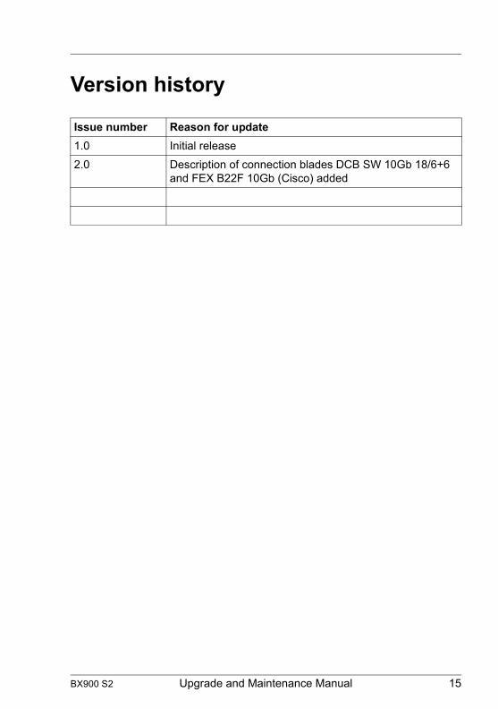
Version history
Issue number Reason for update1.0 Initial release2.0 Description of connection blades DCB SW 10Gb 18/6+6
and FEX B22F 10Gb (Cisco) added
BX900 S2 Upgrade and Maintenance Manual 15

© c
ogni
tas.
Ges
ells
chft
für T
echn
ik-D
okum
enta
tion
mbH
201
1 P
fad:
C:\P
rogr
amm
e\FC
T\tim
_app
\tim
_loc
al\w
ork\
WA
LTE
R\O
BJ_
DO
KU
-136
50-0
01.fm
16 Upgrade and Maintenance Manual BX900 S2

1 IntroductionThis Upgrade and Maintenance Manual provides instructions for the following procedures:
● Upgrading the system unit configuration by adding optional hardware components
● Upgrading the system unit configuration by replacing existing hardware components with superior ones.
● Replacing defective hardware components
I For information about upgrading and maintaining of server blades and storage blades, please refer to the relevant upgrade and maintenance manuals.
If the firmware version of the management blade is changed, the menu in the Web interface and the command line interface might be changed.
V CAUTION!
The document at hand comprises procedures of a wide range of complexity. Check the profile of qualification for technicians before assigning tasks. Before you start, carefully read "Classification of procedures" on page 22.
BX900 S2 Upgrade and Maintenance Manual 17

Introduction
© c
ogni
tas.
Ges
ells
chft
für T
echn
ik-D
okum
enta
tion
mbH
201
1 P
fad:
C:\P
rogr
amm
e\FC
T\tim
_app
\tim
_loc
al\w
ork\
WA
LTE
R\O
BJ_
DO
KU
-136
51-0
01.fm
1.1 Where to find which information?
While the Upgrade and Maintenance Manual focuses on upgrade and maintenance procedures to bring the system unit back to normal operation, additional manuals provide detailed background information on system unit components such as server blades, storage blades, connection blades and management blades.
For information on documents you need to have with you when leaving for maintaining a server see "Documents you need at hand" on page 27.
I PRIMERGY manuals are available in PDF format on the ServerView Suite DVD 2. The ServerView Suite DVD 2 is part of the ServerView Suite supplied with every server.
If you no longer have the ServerView Suite DVDs, you can obtain the relevant current versions using the order number U15000-C289 (the order number for the Japanese market: please refer to the configurator of the server http://jp.fujitsu.com/platform/server/primergy/system/).
The PDF files of the manuals can also be downloaded free of charge from the Internet. The overview page showing the online documentation available on the Internet can be found using the URL (for EMEA market): http://manuals.ts.fujitsu.com. The PRIMERGY server documentation can be accessed using the Industry standard servers navigation option.
For the Japanese market:
Please refer to the following URL for the latest product manuals:http://jp.fujitsu.com/platform/server/primergy/manual/
Before using the product, please check for additional information that may be available under the following URL:http://jp.fujitsu.com/platform/server/primergy/products/note/
18 Upgrade and Maintenance Manual BX900 S2

Introduction
1.2 Notational conventions
The following notational conventions are used in this manual:
Text in italics indicates commands or menu itemsfixed font indicates system outputsemi-bold fixed font
indicates text to be entered by the user
"Quotation marks" indicate names of chapters and terms that are being emphasized
Ê describes activities that must be performed in the order shown
[Abc] indicates keys on the keyboardV CAUTION! Pay particular attention to texts marked with this symbol!
Failure to observe this warning may endanger your life, destroy the system or lead to the loss of data.
I indicates additional information, notes and tips
indicates the procedure category in terms of complexity and qualification requirements, see "Classification of procedures" on page 22
indicates the average task duration, see "Average task duration" on page 24
BX900 S2 Upgrade and Maintenance Manual 19

Introduction
© c
ogni
tas.
Ges
ells
chft
für T
echn
ik-D
okum
enta
tion
mbH
201
1 P
fad:
C:\P
rogr
amm
e\FC
T\tim
_app
\tim
_loc
al\w
ork\
WA
LTE
R\O
BJ_
DO
KU
-136
51-0
01.fm
20 Upgrade and Maintenance Manual BX900 S2

2 Before you startBefore you start any upgrade or maintenance task, please proceed as follows:
Ê Carefully read the safety instructions in chapter "Important information" on page 29.
Ê Make sure that all necessary manuals are available. Refer to the documentation overview in section "Documents you need at hand" on page 27. Print the PDF files if required.
Ê Make yourself familiar with the procedure categories introduced in section "Classification of procedures" on page 22.
Ê Ensure that all required tools are available according to section "Tools you need at hand" on page 25.
Installing optional components
The "PRIMERGY BX900 S2 Blade Server System Unit Operating manual" gives an introduction to system unit features and provides an overview of available hardware options.
Use the Fujitsu ServerView BX900 Remote Management software to prepare hardware expansions. ServerView Suite documentation is available online at http://manuals.ts.fujitsu.com or from the ServerView Suite DVD 2 supplied with your PRIMERGY server.
I For the latest information on hardware options, refer to your system unit’s hardware configurator available online at the following address:
for the EMEA market:http://ts.fujitsu.com/products/standard_servers/index.html
for the Japanese market:http://jp.fujitsu.com/platform/server/primergy/system/
Please contact your local Fujitsu customer service partner for details on how to order expansion kits or spare parts. Use the Fujitsu Illustrated Spares Catalog to identify the required spare part and obtain technical data and order information. Illustrated Spares catalogs are available online at http://manuals.ts.fujitsu.com/illustrated_spares (EMEA market only).
BX900 S2 Upgrade and Maintenance Manual 21

Before you start
© c
ogni
tas.
Ges
ells
chft
für T
echn
ik-D
okum
enta
tion
mbH
201
1 P
fad:
C:\P
rogr
amm
e\FC
T\tim
_app
\tim
_loc
al\w
ork\
WA
LTE
R\O
BJ_
DO
KU
-136
52-0
01.fm
Replacing a defective component
The global error indicators on rear side of the system unit as well as local diagnostic LEDs on the ServerView Local Service Display for Blade (hereinafter referred to as Local Service Display) report defective hardware components that need to be replaced. For further information on the controls and indicators of your system unit, refer to the section "Connectors and indicators" on page 179.
If the defective component is a customer replaceable unit included in the CSS concept (Customer Self Service, only available for EMEA market), the CSS indicators on the front and rear side of the system unit will light up.
2.1 Classification of procedures
The complexity of maintenance procedures varies significantly. Procedures have been assigned to one of three unit categories, indicating the level of difficulty and required qualification.
At the beginning of each procedure, the involved unit type is indicated by one of the symbols introduced in this section.
I Please ask your local Fujitsu service center for more detailed information.
2.1.1 Customer Replaceable Units (CRU)
Customer Replaceable Units are intended for customer self service and may be installed or replaced as hot-plug components during operation.
I Components that the customer is entitled to replace may differ according to the service form in his country.
Hot-plug components increase system availability and guarantee a high degree of data integrity and fail-safe performance. Procedures can be carried out without shutting down the system unit or going offline.
Customer Replaceable Units (CRU)
22 Upgrade and Maintenance Manual BX900 S2

Before you start
Components that are handled as Customer Replaceable Units
– Hot-plug PSUs– Hot-plug fan modules– Fan units inside PSUs and fan modules
2.1.2 Upgrade and Repair Units (URU)
Upgrade and Repair Units are non hot-plug components that can be ordered separately to be installed as options (Upgrade Units) or are available to the customer through customer self service (Repair Units).
I Server management error messages and diagnostic indicators on the front panel will report defective Upgrade and Repair Units as customer replaceable CSS components.
Upgrade and repair procedures require complex configuration tasks.
V CAUTION!
The device may be seriously damaged or cause damage if it is opened without authorization or if repairs are attempted by unauthorized and untrained personnel.
Components that are handled as Upgrade Units
– Management blades– Connection blades
Upgrade and Repair Units (URU)
BX900 S2 Upgrade and Maintenance Manual 23
Before you start
© c
ogni
tas.
Ges
ells
chft
für T
echn
ik-D
okum
enta
tion
mbH
201
1 P
fad:
C:\P
rogr
amm
e\FC
T\tim
_app
\tim
_loc
al\w
ork\
WA
LTE
R\O
BJ_
DO
KU
-136
52-0
01.fm
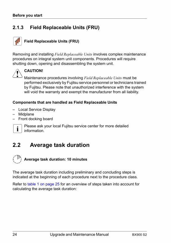
2.1.3 Field Replaceable Units (FRU)
Removing and installing Field Replaceable Units involves complex maintenance procedures on integral system unit components. Procedures will require shutting down, opening and disassembling the system unit.
V CAUTION!
Maintenance procedures involving Field Replaceable Units must be performed exclusively by Fujitsu service personnel or technicians trained by Fujitsu. Please note that unauthorized interference with the system will void the warranty and exempt the manufacturer from all liability.
Components that are handled as Field Replaceable Units
– Local Service Display– Midplane– Front docking board
I Please ask your local Fujitsu service center for more detailed information.
2.2 Average task duration
The average task duration including preliminary and concluding steps is indicated at the beginning of each procedure next to the procedure class.
Refer to table 1 on page 25 for an overview of steps taken into account for calculating the average task duration:
Field Replaceable Units (FRU)
Average task duration: 10 minutes
24 Upgrade and Maintenance Manual BX900 S2

Before you start
2.3 Tools you need at hand
When preparing the maintenance task, ensure that all required tools are available according to the overview below. You will find a list of required tools at the beginning of each procedure.
Step included Explanation
System unit shutdown no
Shutdown time depends on hardware and software configuration and may vary significantly.
Software tasks necessary before maintenance are described in section "Starting the maintenance task" on page 63".
Rack removal, disassembly yes making the system unit available, removing
the system unit from the rack (if applicable)
Transport noTransporting the system unit to the service table (where required) depends on local customer conditions.
Maintenance procedures yes maintenance procedures including
preliminary and concluding software tasks
Transport noReturning the system unit to its installation site (where required) depends on local customer conditions.
Assembly, rack installation yes reassembling the system unit, installing the
system unit in the rack (if applicable)
Starting up noBooting time depends on hardware and software configuration and may vary significantly.
Table 1: Calculation of the average task duration
BX900 S2 Upgrade and Maintenance Manual 25

Before you start
© c
ogni
tas.
Ges
ells
chft
für T
echn
ik-D
okum
enta
tion
mbH
201
1 P
fad:
C:\P
rogr
amm
e\FC
T\tim
_app
\tim
_loc
al\w
ork\
WA
LTE
R\O
BJ_
DO
KU
-136
52-0
01.fm
Screw driver/Bit insert Screw Usage Type
PhillipsPH2 / (+) No. 2hexagonal cross SW5 / PZ2 Midplane
M3 x 16,5 mm
MS30165I000
PhillipsPH2 / (+) No. 2hexagonal cross SW5 / PZ2 Midplane
M3 x 10 mm
FBTU1127010
PhillipsPH2 / (+) No. 2hexagonal cross SW5 / PZ2 Rear chassis
M3 x 6 mm
MS30060H250
PhillipsPH0 / (+) No. 0hexagonal cross SW5 / PZ2
Local Service Display stop bracket
M3 x 5 mm
MS30050FCB0
Table 2: List of used screws
26 Upgrade and Maintenance Manual BX900 S2
Before you start
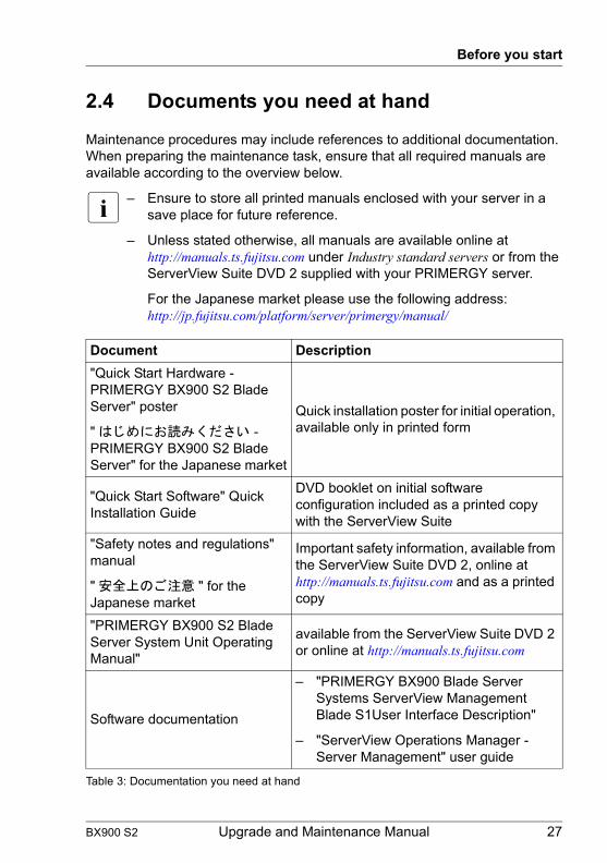
2.4 Documents you need at hand
Maintenance procedures may include references to additional documentation. When preparing the maintenance task, ensure that all required manuals are available according to the overview below.
I – Ensure to store all printed manuals enclosed with your server in a save place for future reference.
– Unless stated otherwise, all manuals are available online at http://manuals.ts.fujitsu.com under Industry standard servers or from the ServerView Suite DVD 2 supplied with your PRIMERGY server.
For the Japanese market please use the following address: http://jp.fujitsu.com/platform/server/primergy/manual/
Document Description"Quick Start Hardware - PRIMERGY BX900 S2 Blade Server" poster
" はじめにお読みください - PRIMERGY BX900 S2 Blade Server" for the Japanese market
Quick installation poster for initial operation, available only in printed form
"Quick Start Software" Quick Installation Guide
DVD booklet on initial software configuration included as a printed copy with the ServerView Suite
"Safety notes and regulations" manual
" 安全上のご注意 " for the Japanese market
Important safety information, available from the ServerView Suite DVD 2, online at http://manuals.ts.fujitsu.com and as a printed copy
"PRIMERGY BX900 S2 Blade Server System Unit Operating Manual"
available from the ServerView Suite DVD 2 or online at http://manuals.ts.fujitsu.com
Software documentation
– "PRIMERGY BX900 Blade Server Systems ServerView Management Blade S1User Interface Description"
– "ServerView Operations Manager - Server Management" user guide
Table 3: Documentation you need at hand
BX900 S2 Upgrade and Maintenance Manual 27

Before you start
© c
ogni
tas.
Ges
ells
chft
für T
echn
ik-D
okum
enta
tion
mbH
201
1 P
fad:
C:\P
rogr
amm
e\FC
T\tim
_app
\tim
_loc
al\w
ork\
WA
LTE
R\O
BJ_
DO
KU
-136
52-0
01.fm
Illustrated Spares catalog
Spare parts identification and information system (EMEA market only), available for online use or download (Windows OS) at http://manuals.ts.fujitsu.com/illustrated_spares or from the CSS component view of the ServerView Operations Manager
Glossary available from the ServerView Suite DVD 2 or online at http://manuals.ts.fujitsu.com
"Warranty" manual
" 保証書 " for the Japanese market
Important information on warranty regulations, recycling and service, available from the ServerView Suite DVD 2, online at http://manuals.ts.fujitsu.com or as a printed copy
"Returning used devices" manual for the EMEA market Recycling and contact information,
available from the ServerView Suite DVD 2, online at http://manuals.ts.fujitsu.com or as a printed copy
"Service Desk" leaflet
" サポート&サービス " for the Japanese market
Additional documentation
– Rack documentation– Server blade documentation– Storage blade documentation– Connection blade documentation
Third party documentation– Operating system documentation,
online help
– Peripherals documentation
Document Description
Table 3: Documentation you need at hand
28 Upgrade and Maintenance Manual BX900 S2

3 Important informationV CAUTION!
Before installing and starting up a device, please observe the safety instructions listed in the following section. This will help you to avoid making serious errors that could impair your health, damage the device and endanger the data base.
I Keep this operating manual and the other documentation (such as the technical manual, documentation DVD) close to the device. All documentation must be included if the equipment is passed on to a third party.
3.1 Safety instructions
I The following safety instructions are also provided in the manual "Safety Notes and Regulations" or " 安全上のご注意 ".
This device meets the relevant safety regulations for IT equipment. If you have any questions about whether you can install the server in the intended environment, please contact your sales outlet or our customer service team.
V CAUTION!
● The actions described in this manual shall be performed by technical specialists. A technical specialist is a person who is trained to install the server including hardware and software.
● Repairs to the device that do not relate to CSS failures shall be performed by service personnel. Please note that unauthorized interference with the system will void the warranty and exempt the manufacturer from all liability.
● Any failure to observe the guidelines in this manual, and any improper repairs could expose the user to risks (electric shock, energy hazards, fire hazards) or damage the equipment.
● Before installing/removing internal options to/from the server, turn off the server, all peripheral devices, and any other connected devices. Also unplug all power cords from the power outlet. Failure to do so can cause electric shock.
BX900 S2 Upgrade and Maintenance Manual 29

Important information
© c
ogni
tas.
Ges
ells
chft
für T
echn
ik-D
okum
enta
tion
mbH
201
1 P
fad:
C:\P
rogr
amm
e\FC
T\tim
_app
\tim
_loc
al\w
ork\
WA
LTE
R\O
BJ_
DO
KU
-136
53-0
01.fm
Before starting up
● During installation and before operating the device, observe the instructions on environmental conditions for your device.
● If the device is brought in from a cold environment, condensation may form both inside and on the outside of the device.
Wait until the device has acclimatized to room temperature and is absolutely dry before starting it up. Material damage may be caused to the device if this requirement is not observed.
● Transport the device only in the original packaging or in packaging that protects it from knocks and jolts.For the Japanese market, transporting the device in its original packaging does not apply.
Installation and operation
● This unit should not be operated in ambient temperatures above 35 °C.
● If the unit is integrated into an installation that draws power from an industrial power supply network with an IEC309 connector, the power supply's fuse protection must comply with the requirements for non-industrial power supply networks for type B connectors.
● The unit automatically adjusts itself to a mains voltage in a range of 100 VAC to 240 VAC. Ensure that the local mains voltage lies within these limits.
● This device must only be connected to properly grounded power outlets or connected to the grounded rack internal power distribution system with tested and approved power cords.
● Ensure that the device is connected to a properly grounded power outlet close to the device.
● Ensure that the power sockets on the device and the properly grounded power outlets are easily accessible.
● The On/Off button or the main power switch (if present) does not isolate the device from the mains power supply. In case of repair or servicing disconnect the device completely from the mains power supply, unplug all power plugs from the properly grounded power outlets.
30 Upgrade and Maintenance Manual BX900 S2

Important information
● Always connect the server and the attached peripherals to the same power circuit. Otherwise you run the risk of losing data if, for example, the server is still running but a peripheral device (e.g. memory subsystem) fails during a power outage.
● Data cables must be adequately shielded.
● Ethernet cabling has to comply with EN 50173 and EN 50174-1/2 standards or ISO/IEC 11801 standard respectively. The minimum requirement is a Category 5 shielded cable for 10/100 Ethernet, or a Category 5e cable for Gigabit Ethernet.
● Route the cables in such a way that they do not create a potential hazard (make sure no-one can trip over them) and that they cannot be damaged. When connecting the server, refer to the relevant instructions in this manual.
● Never connect or disconnect data transmission lines during a storm (risk of lightning hazard).
● Make sure that no objects (e.g. jewelry, paperclips etc.) or liquids can get inside the server (risk of electric shock, short circuit).
● In emergencies (e.g. damaged casing, controls or cables, penetration of liquids or foreign bodies), contact the system administrator or your customer service team. Only disconnect the system from the mains power supply if there is no risk of harming yourself.
● Proper operation of the system (in accordance with IEC 60950-1 resp. EN 60950-1) is only ensured if the casing is completely assembled and the rear covers for the installation slots have been fitted (electric shock, cooling, fire protection, interference suppression).
● Only install system expansions that satisfy the requirements and rules governing safety and electromagnetic compatibility and those relating to telecommunication terminals. If you install other expansions, they may damage the system or violate the safety regulations. Information on which system expansions are approved for installation can be obtained from our customer service center or your sales outlet.
● The components marked with a warning notice (e.g. lightning symbol) may only be opened, removed or exchanged by authorized, qualified personnel. Exception: CSS components can be replaced.
● The warranty is void if the server is damaged during installation or replacement of system expansions.
BX900 S2 Upgrade and Maintenance Manual 31

Important information
© c
ogni
tas.
Ges
ells
chft
für T
echn
ik-D
okum
enta
tion
mbH
201
1 P
fad:
C:\P
rogr
amm
e\FC
T\tim
_app
\tim
_loc
al\w
ork\
WA
LTE
R\O
BJ_
DO
KU
-136
53-0
01.fm
● Only set screen resolutions and refresh rates that are specified in the operating manual for the monitor. Otherwise, you may damage your monitor. If you are in any doubt, contact your sales outlet or customer service center.
● Before installing/removing internal options to/from the server, turn off the server, all peripheral devices, and any other connected devices. Also unplug all power cords from the outlet. Failure to do so can cause electric shock.
● Do not damage or modify internal cables or devices. Doing so may cause a device failure, fire, or electric shock and will void the warranty and exempt the manufacturer from all liability.
● Devices inside the server remain hot after shutdown. Wait for a while after shutdown before installing or removing internal options.
● The circuit boards and soldered parts of internal options are exposed and can be damaged by static electricity. To ensure reliable protection, if you are wearing an earthing band on your wrist when working with this type of module, connect it to an unpainted, non-conducting metal part of the system.
● Do not touch the circuitry on boards or soldered parts. Hold the metallic areas or the edges of the circuit boards.
● Install the screw removed during installation/detaching internal options in former device/position. To use a screw of the different kind can cause a breakdown of equipment.
● The installation indicated on this document is sometimes changed to the kind of possible options without notice.
32 Upgrade and Maintenance Manual BX900 S2

Important information
Batteries
● Incorrect replacement of batteries may lead to a risk of explosion. The batteries may only be replaced with identical batteries or with a type recommended by the manufacturer.
● Do not throw batteries into the trash can.
● Batteries must be disposed of in accordance with local regulations concerning special waste.
● Make sure that you insert the battery the right way round.
● The battery used in this device may present a fire or chemical burn hazard if mistreated. Do not disassemble, heat about 100 °C (212F), or incinerate the battery.
● All batteries containing pollutants are marked with a symbol (a crossed-out garbage can). In addition, the marking is provided with the chemical symbol of the heavy metal decisive for the classification as a pollutant:
Cd Cadmium Hg Mercury Pb Lead
Working with CDs/DVDs/BDs and optical drives
When working with devices with optical drives, these instructions must be followed.
V CAUTION!
● Only use CDs/DVDs/BDs that are in perfect condition, in order to prevent data loss, equipment damage and injury.
● Check each CD/DVD/BD for damage, cracks, breakages etc. before inserting it in the drive.
Note that any additional labels applied may change the mechanical properties of a CD/DVD/BD and cause imbalance.
Damaged and imbalanced CDs/DVDs/BDs can break at high drive speeds (data loss).
Under certain circumstances, sharp CD/DVD/BD fragments can pierce the cover of the optical drive (equipment damage) and can fly out of the device (danger of injury, particularly to uncovered body parts such as the face or neck).
BX900 S2 Upgrade and Maintenance Manual 33

Important information
© c
ogni
tas.
Ges
ells
chft
für T
echn
ik-D
okum
enta
tion
mbH
201
1 P
fad:
C:\P
rogr
amm
e\FC
T\tim
_app
\tim
_loc
al\w
ork\
WA
LTE
R\O
BJ_
DO
KU
-136
53-0
01.fm
● High humidity and airborne dust levels are to be avoided. Electric shocks and/or server failures may be caused by liquids such as water, or metallic items, such as paper clips, entering a drive.
● Shocks and vibrations are also to be avoided.
● Do not insert any objects other than the specified CDs/DVDs/BDs.
● Do not pull on, press hard, or otherwise handle the CD/DVD/BD tray roughly.
● Do not disassemble the optical drive.
● Before use, clean the optical disk tray using a soft, dry cloth.
● As a precaution, remove disks from the optical drive when the drive is not to be used for a long time. Keep the optical disk tray closed to prevent foreign matter, such as dust, from entering the optical drive.
● Hold CDs/DVDs/BDs by their edges to avoid contact with the disk surface.
● Do not contaminate the CD/DVD/BD surface with fingerprints, oil, dust, etc. If dirty, clean with a soft, dry cloth, wiping from the center to the edge. Do not use benzene, thinners, water, record sprays, antistatic agents, or silicone-impregnated cloth.
● Be careful not to damage the CD/DVD/BD surface.
● Keep the CDs/DVDs/BDs away from heat sources.
● Do not bend or place heavy objects on CDs/DVDs/BDs.
● Do not write with ballpoint pen or pencil on the label (printed) side.
● Do not attach stickers or similar to the label side. Doing so may cause rotational eccentricity and abnormal vibrations.
● When a CD/DVD/BD is moved from a cold place to a warm place, moisture condensation on the CD/DVD/BD surface can cause data read errors. In this case, wipe the CD/DVD/BD with a soft, dry cloth then let it air dry. Do not dry the CD/DVD/BD using devices such as a hair dryer.
● To avoid dust, damage, and deformation, keep the CD/DVD/BD in its case whenever it is not in use.
34 Upgrade and Maintenance Manual BX900 S2
Important information
● Do not store CDs/DVDs/BDs at high temperatures. Areas exposed to prolonged direct sunlight or near heating appliances are to be avoided.
I You can prevent damage from the optical drive and the CDs/DVDs/BDs, as well as premature wear of the disks, by observing the following suggestions:
– Only insert disks in the drive when needed and remove them after use.
– Store the disks in suitable sleeves.– Protect the disks from exposure to heat and direct sunlight.
Laser information
The optical drive complies with IEC 60825-1 laser class 1.
V CAUTION!
The optical drive contains a light-emitting diode (LED), which under certain circumstances produces a laser beam stronger than laser class 1. Looking directly at this beam is dangerous.
Never remove parts of the optical drive casing!
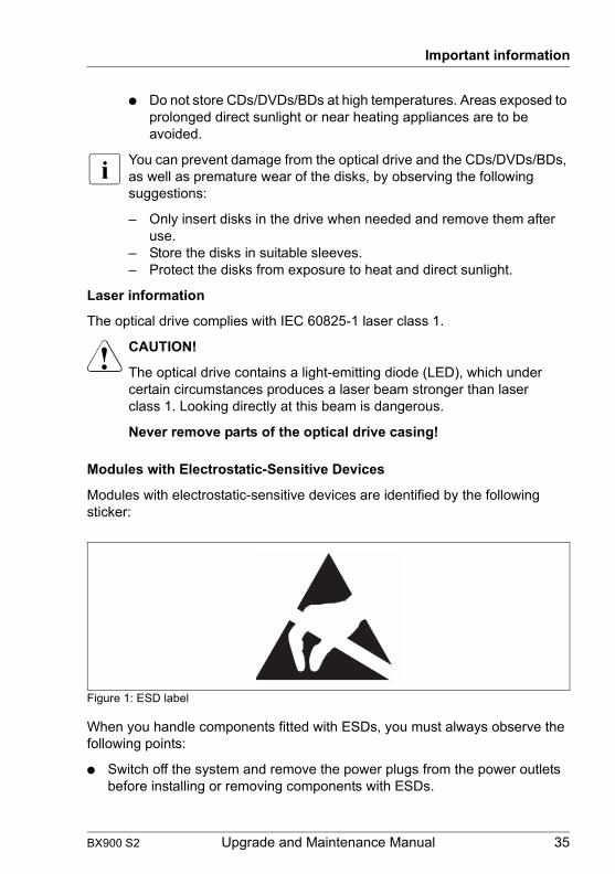
Modules with Electrostatic-Sensitive Devices
Modules with electrostatic-sensitive devices are identified by the following sticker:
Figure 1: ESD label
When you handle components fitted with ESDs, you must always observe the following points:
● Switch off the system and remove the power plugs from the power outlets before installing or removing components with ESDs.
BX900 S2 Upgrade and Maintenance Manual 35

Important information
© c
ogni
tas.
Ges
ells
chft
für T
echn
ik-D
okum
enta
tion
mbH
201
1 P
fad:
C:\P
rogr
amm
e\FC
T\tim
_app
\tim
_loc
al\w
ork\
WA
LTE
R\O
BJ_
DO
KU
-136
53-0
01.fm
● You must always discharge static build-up (e.g. by touching a grounded object) before working with such components.
● Any devices or tools that are used must be free of electrostatic charge.
● Wear a suitable grounding cable that connects you to the external chassis of the system unit.
● Always hold components with ESDs at the edges or at the points marked green (touch points).
● Do not touch any connectors or conduction paths on an ESD.
● Place all the components on a pad which is free of electrostatic charge.
I For a detailed description of how to handle ESD components, see the relevant European or international standards (EN 61340-5-1, ANSI/ESD S20.20).
Transporting the system unit
● Only transport the system unit in its original packaging or in suitable packaging which protects it from knocks and jolts.
For the Japanese market, transporting the device in its original packaging does not apply.
Only unpack the system unit at the place where you want to set it up.
● Ask someone for help with carrying the system unit. Because the PRIMERGY BX900 S2 system unit is large and heavy, at least three people are needed.
● Before lifting the system unit, remove all server blades, storage blades, connection blades, management blades, all power supply units, fan units and dummy modules to reduce the weight.
● To lift or carry the system unit, mount the handles on the long sides of the unit.
● Only lift or carry the system unit by the handles on the long sides.
● Never lift or carry the system unit by the handles on the front or back.
36 Upgrade and Maintenance Manual BX900 S2

Important information
Notes on installation into the rack
● For safety reasons, at least three people are required to install the system unit in the rack because of its weight and size.
Refer to section 5.2 "Installing/removing the system unit" in the "PRIMERGY BX900 S2 Blade Server System Operating Manual".(For the Japanese market, please refer to " 安全上のご注意 ".)
● Before lifting the system unit, remove all server blades, storage blades, connection blades, management blades, all power supply units, fan units and dummy modules to reduce the weight.
● To lift or carry the system unit, always use the handles on the long sides.
● Never lift or carry the system unit by the handles on the front or back of the unit.
● For safety reasons, no more than one unit may be removed from the rack at any one time during installation or maintenance work.
● Make sure that the anti-tilt plate is correctly mounted when you set up the rack.
● The rack may tip over if more than one unit is removed at the same time.
● Before connecting or disconnecting cables, read the notes in the chapter "Important Notes" in the technical manual for the relevant rack. The technical manual for the rack is supplied with the rack.
● The rack must be connected to the mains by an authorized specialist (electrician).
● If the server system is integrated in a rack installation that receives power from an industrial (public) power supply network with the IEC309 connector, the (public) power supply protection must comply with the requirements for the non-industrial (public) power supply networks for the type B connector.
● The power supply for the rack should be distributed over the three phases of a three-phase mains connection.
BX900 S2 Upgrade and Maintenance Manual 37

Important information
© c
ogni
tas.
Ges
ells
chft
für T
echn
ik-D
okum
enta
tion
mbH
201
1 P
fad:
C:\P
rogr
amm
e\FC
T\tim
_app
\tim
_loc
al\w
ork\
WA
LTE
R\O
BJ_
DO
KU
-136
53-0
01.fm
3.2 CE conformity
The system complies with the requirements of the EC directives 2004/108/EC regarding "Electromagnetic Compatibility" and 2006/95/EC "Low Voltage Directive". This is indicated by the CE marking (CE = Communauté Européenne).
38 Upgrade and Maintenance Manual BX900 S2

Important information
3.3 FCC Class A Compliance Statement
If there is an FCC statement on the device, it applies to the products covered in this manual, unless otherwise specified herein. The statement for other products will appear in the accompanying documentation.
NOTE:
This equipment has been tested and found to comply with the limits for a "Class A" digital device, pursuant to Part 15 of the FCC rules and meets all requirements of the Canadian Interference-Causing Equipment Standard ICES-003 for digital apparatus. These limits are designed to provide reasonable protection against harmful interference in a residential installation. This equipment generates, uses and can radiate radio frequency energy and, if not installed and used in strict accordance with the instructions, may cause harmful interference to radio communications. However, there is no warranty that interference will not occur in a particular installation. If this equipment does cause harmful interference to radio or television reception, which can be determined by turning the equipment off and on, the user is encouraged to try to correct the interference by one or more of the following measures:
● Reorient or relocate the receiving antenna.
● Increase the separation between equipment and the receiver.
● Connect the equipment into an outlet on a circuit different from that to which the receiver is connected.
● Consult the dealer or an experienced radio/TV technician for help.
Fujitsu is not responsible for any radio or television interference caused by unauthorized modifications of this equipment or the substitution or attachment of connecting cables and equipment other than those specified by Fujitsu. The correction of interferences caused by such unauthorized modification, substitution or attachment will be the responsibility of the user.
The use of shielded I/O cables is required when connecting this equipment to any and all optional peripheral or host devices. Failure to do so may violate FCC and ICES rules.
WARNING:
This is a class A product. In a domestic environment this product may cause radio interference in which case the user may be required to take adequate measures.
BX900 S2 Upgrade and Maintenance Manual 39

Important information
© c
ogni
tas.
Ges
ells
chft
für T
echn
ik-D
okum
enta
tion
mbH
201
1 P
fad:
C:\P
rogr
amm
e\FC
T\tim
_app
\tim
_loc
al\w
ork\
WA
LTE
R\O
BJ_
DO
KU
-136
53-0
01.fm
3.4 Environmental protection
Environmentally-friendly product design and development
This product has been designed in accordance with the Fujitsu standard for "environmentally friendly product design and development". This means that key factors such as durability, selection and labeling of materials, emissions, packaging, ease of dismantling and recycling have been taken into account.
This saves resources and thus reduces the harm done to the environment. Further information can be found at:
– http://ts.fujitsu.com/products/standard_servers/index.html (for the EMEA market)– http://jp.fujitsu.com/platform/server/primergy/concept/ (for the Japanese
market)
Energy-saving information
Devices that do not need to be constantly switched on should be switched off until they are needed as well as during long breaks and after completion of work.
Packaging information
This packaging information doesn’t apply to the Japanese market.
Do not throw away the packaging. You may need it later for transporting the system. If possible, the equipment should only be transported in its original packaging.
Information on handling consumables
Please dispose of printer consumables and batteries in accordance with the applicable national regulations.
In accordance with EU directives, batteries must not be disposed of with unsorted domestic waste. They can be returned free of charge to the manufacturer, dealer or an authorized agent for recycling or disposal.
All batteries containing pollutants are marked with a symbol (a crossed-out garbage can). They are also marked with the chemical symbol for the heavy metal that causes them to be categorized as containing pollutants:
Cd CadmiumHg MercuryPb Lead
40 Upgrade and Maintenance Manual BX900 S2
Important information
Labels on plastic casing parts
Please avoid sticking your own labels on plastic parts wherever possible, since this makes it difficult to recycle them.
Returns, recycling and disposal
Please handle returns, recycling and disposal in accordance with local regulations.
Details regarding the return and recycling of devices and consumables within Europe can also be found in the "Returning used devices" manual, via your local Fujitsu branch or from our recycling center in Paderborn:
Fujitsu Technology SolutionsRecycling CenterD-33106 Paderborn
Tel. +49 5251 525 1410Fax +49 5251 525 32 1410
The device must not be disposed of with domestic waste. This device is labeled in compliance with European directive 2002/96/EC on waste electrical and electronic equipment (WEEE).
This directive sets the framework for returning and recycling used equipment and is valid across the EU. When returning your used device, please use the return and collection systems available to you. Further information can be found at http://ts.fujitsu.com/recycling.
BX900 S2 Upgrade and Maintenance Manual 41

Important information
© c
ogni
tas.
Ges
ells
chft
für T
echn
ik-D
okum
enta
tion
mbH
201
1 P
fad:
C:\P
rogr
amm
e\FC
T\tim
_app
\tim
_loc
al\w
ork\
WA
LTE
R\O
BJ_
DO
KU
-136
53-0
01.fm
42 Upgrade and Maintenance Manual BX900 S2

4 Basic hardware procedures
4.1 Using diagnostics information
The "PRIMERGY BX900 S2 Blade Server System Unit Operating manual" gives an introduction to system unit features and provides an overview of available hardware options.
Use the Fujitsu ServerView BX900 Remote Management software to plan the upgrade or replacement of hardware components. ServerView Suite documentation is available online at http://manuals.ts.fujitsu.com or from the ServerView Suite DVD 2 supplied with your PRIMERGY server. Please refer to the following ServerView Suite topics:
– Operation– Maintenance
Please contact your local Fujitsu customer service partner for details on the service concept and on how to order expansion kits or spare parts. Use the Fujitsu Illustrated Spares Catalog to identify the required spare part and obtain technical data and order information. Illustrated Spares catalogs are available online at http://manuals.ts.fujitsu.com/illustrated_spares (EMEA market only).
Perform the following diagnostics procedures to identify defective system units and components:
BX900 S2 Upgrade and Maintenance Manual 43

Basic hardware procedures
© c
ogni
tas.
Ges
ells
chft
für T
echn
ik-D
okum
enta
tion
mbH
201
1 P
fad:
C:\P
rogr
amm
e\FC
T\tim
_app
\tim
_loc
al\w
ork\
WA
LTE
R\O
BJ_
DO
KU
-136
54-0
01.fm
4.1.1 Accessing the management blade web interface
For checking the current system status and administration of the system unit, connect a field service terminal (FST, e.g. notebook) to the management blade and login to the management blade web interface.
Figure 2: Connectors on the management blade
Ê Connect the FST to the service LAN connector (1) of the management blade. During maintaining working, FST has to be connected with the connector of Management LAN.
I – If two management blades are installed, connect the FST to the master management blade. The status indicator of the master management blade glows yellow.
– If you need access to server blades or connection blades, ask the customer for the IP address of the management LAN and connect the FST to the management LAN connector.
– Customers must use the Up port (4) while the Down port (5) is reserved for service personnel.
– The FST must be on the same LAN with the same subnet as the service LAN port or as the management LAN port respectively.
Ê Launch a web browser and enter the Management Agent Administrative URL to login to the management blade web interface. For further information, refer to the "PRIMERGY BX900 Blade Server Systems ServerView Management Blade S1 User Interface Description".
I If you don't know the Management Agent Administrative URL, proceed as follows.
1 2 3 4 5
44 Upgrade and Maintenance Manual BX900 S2

Basic hardware procedures
Ê Connect the FST to the serial port of the management blade (3) and open a terminal session, see the "PRIMERGY BX900 Blade Server Systems ServerView Management Blade S1 User Interface Description".
Ê Open the Management Agent – Management Agent Information menu to view the Management Agent Administrative URL.
Ê Login to the management blade web interface as described above.
4.1.2 Locating the defective system unit
When working in a datacenter environment, switch on the ID indicator on the front and rear of the system unit (see section "Connectors and indicators" on page 179) for easy identification.
Ê Press the ID button on the Local Service Display or on the management blade or use the ServerView Operations Manager or the management blade web interface, to switch on the ID indicators.
Ê When using ServerView Operations Manager to toggle the ID indicator, choose Single System View and press the Locate button.
Ê When using the management blade web interface to toggle the ID indicator, press the Locate button in the status frame.
Ê Remember to switch off the ID indicator after the maintenance task has been concluded successfully.
4.1.3 Determining the error class
Failure events are assigned to one of two error classes:
– Global Error events that need to be resolved by maintenance personnel
– Customer Self Service (CSS) error events that may be resolved by operating personnel
Customer Replaceable Units (CRU)
BX900 S2 Upgrade and Maintenance Manual 45
Basic hardware procedures
© c
ogni
tas.
Ges
ells
chft
für T
echn
ik-D
okum
enta
tion
mbH
201
1 P
fad:
C:\P
rogr
amm
e\FC
T\tim
_app
\tim
_loc
al\w
ork\
WA
LTE
R\O
BJ_
DO
KU
-136
54-0
01.fm
Global Error and CSS indicate, if the defective component is a customer replaceable unit or if maintenance personnel needs to be dispatched to replace the part.
I The indicators also light up in standby mode and after a system unit restart due to a power failure.
46 Upgrade and Maintenance Manual BX900 S2

Basic hardware procedures
4.1.3.1 Global Error indicator
Ê Check the Global Error indicator on the front panel or management blade of the system unit (see section "Connectors and indicators" on page 179).
Ê For further diagnostics, proceed as follows:
– Check the status frame of the management blade web interface, see the "PRIMERGY BX900 Blade Server Systems ServerView Management Blade S1 User Interface Description".
– Check the System Event Log (SEL) as described in section "Viewing the SEL" on page 71.
4.1.3.2 Customer Self Service (CSS) indicator
Ê Check the CSS indicator on the front panel or management blade of the system unit (see section "Connectors and indicators" on page 179).
Indicator Status Description
Global error indicator
off no critical event (non CSS component)
orange onprefailure detected (non CSS component), requires (precautionary) service intervention
orange flashing
non CSS component failure or software / agent related error, requires service intervention
Indicator Status Description
CSS indicator
off no critical event (CSS component)yellow on prefailure detected (CSS component)yellow flashing CSS component failure
BX900 S2 Upgrade and Maintenance Manual 47

Basic hardware procedures
© c
ogni
tas.
Ges
ells
chft
für T
echn
ik-D
okum
enta
tion
mbH
201
1 P
fad:
C:\P
rogr
amm
e\FC
T\tim
_app
\tim
_loc
al\w
ork\
WA
LTE
R\O
BJ_
DO
KU
-136
54-0
01.fm
4.1.4 Locating the defective component
After determining the error class by the CSS or Global Error indicators (see section 4.1.3 on page 45) locate the defective component. There are two ways to do this.
– Local diagnostic indicators on the PSUs, fan modules, connection blades and management blades allow you to identify the defective component (see section "Connectors and indicators" on page 179).
– In the management blade web interface, errors and warnings are displayed simultaneously in the status frame, the navigation frame and the main frame, see the "PRIMERGY BX900 Blade Server Systems ServerView Management Blade S1 User Interface Description" manual.
I For information about upgrading and maintaining server blades and storage blades, please refer to the relevant upgrade and maintenance manuals.
4.2 Opening the rack door
I The following description only applies to the PRIMECENTER rack. For further instructions on opening or closing the 19-inch rack, please refer to the "19-inch Rack for PRIMERGY and RM systems" assembly guide, available online at http://manuals.ts.fujitsu.com or from the ServerView Suite DVD 2 supplied with your PRIMERGY server.
The PRIMECENTER rack is equipped with a split front door. The left-hand door contains an interlocking system that can be locked and opened with a key. Optionally, a revolving door knob can be mounted for key-less locking. To unlock and open the rack, proceed as follows:
Ê Insert and turn the key by counter-clockwise by 180 degrees.If applicable, turn the door knob counter-clockwise by 180 degrees.
Ê Open the left-hand door first, then the right-hand door.
I For further information, refer to the "PRIMECENTER Rack System" assembly guide available online at http://manuals.ts.fujitsu.com or from the ServerView Suite DVD 2 supplied with your PRIMERGY server.
48 Upgrade and Maintenance Manual BX900 S2

Basic hardware procedures
4.3 Shutting down the system unit
V CAUTION!
For further safety information, please refer to chapter "Important information" on page 29.
I This step is only required when upgrading or replacing non-hot plug components.
Ê Inform the system administrator that the system unit will be shut down and put offline.
Ê Terminate all applications of the server blades.
Ê Shut down the system unit by pressing the On/Off button for 2 seconds or via the management blade web interface, see the "PRIMERGY BX900 S2 Blade Server System Unit Operating Manual" for detailed information.
Ê Switch on the ID indicator on the Local Service Display or on the management blade as described in section "Locating the defective system unit" on page 45.
Disconnecting the power cords
Figure 3: Removing the power cord from the PSU cable tie
Ê For each PSU, pull out the locking lever on the PSU cable tie (1) and loosen the loop.
Ê Disconnect the power cords from the PSUs and remove them from the cable ties.
1
BX900 S2 Upgrade and Maintenance Manual 49

Basic hardware procedures
© c
ogni
tas.
Ges
ells
chft
für T
echn
ik-D
okum
enta
tion
mbH
201
1 P
fad:
C:\P
rogr
amm
e\FC
T\tim
_app
\tim
_loc
al\w
ork\
WA
LTE
R\O
BJ_
DO
KU
-136
54-0
01.fm
4.4 Connecting the system unit to the mains
The system unit has six bays for hot-swap power supply units (PSUs). In the base configuration, it is fitted with three PSUs.
V CAUTION!
● Read the information on determining how many PSUs are required (see "Power supply" on page 85).
● The PSUs automatically adjust to a mains voltage between 100 VAC to 240 VAC. The system unit may only be used if the local mains voltage is within the voltage range of the system.
● The 2880 W PSUs may only be connected to 16 A power outlets, a UPS, a 32 A power distribution unit, or CEE sockets. When ordering the system unit, you must specify which socket type is available at the installation location, so that the cables with the appropriate C19 connectors can be supplied.
● For the Japanese market:The standard power supply units (Japanese version) may only be connected to NEMA L6-20, IEC 60320-C20, or NEMA 5-15 sockets.
The HE power supply units may only be connected to NEMA L6-20 or IEC 60320-C20 sockets.
● Always connect the cable first to the PSU and then to the mains.
Ê First connect the insulated C19 connectors of the power cables to the PSUs of the system unit, and then plug the connectors into the UPS, power distribution unit or external sockets.
Ê Ensure that the status indicator on the PSU module is lit green.
I For more information see section "Indicators on the hot-plug power supply units" on page 186.
50 Upgrade and Maintenance Manual BX900 S2

Basic hardware procedures
Securing power cords
Figure 4: Securing power cords
Ê Route the cable through the loop of the cable tie (1).
Ê Pull the cable tie tight to secure the power cable.
1
BX900 S2 Upgrade and Maintenance Manual 51

Basic hardware procedures
© c
ogni
tas.
Ges
ells
chft
für T
echn
ik-D
okum
enta
tion
mbH
201
1 P
fad:
C:\P
rogr
amm
e\FC
T\tim
_app
\tim
_loc
al\w
ork\
WA
LTE
R\O
BJ_
DO
KU
-136
54-0
01.fm
4.5 Switching on the system unit
V CAUTION!
Follow the safety instructions in chapter "Important information" on page 29.
Ê Connect all peripheral cables to the connection blades of the system unit.
Ê Connect and secure the power cords as described in section "Connecting the system unit to the mains" on page 50.
Ê Connect all power cords to the power outlets.
I Make sure that the individual PSUs are connected to different AC sources (phases). This ensures additional AC source (phase) redundancy for high-availability configurations. If only one AC source (phase) fails, the PSUs connected to the other AC sources (phases) remain operational.
Figure 5: Numbering of the PSU bays
Power system with 2 AC sources (phases) availableWith 6 PSUs, you must connect the ones in the top row (PSUs 1, 2 and 3) to the first source (phase) and the ones in the bottom row (PSUs 4, 5 and 6) to the second source (phase).
PSU 1 PSU 2 PSU 3
PSU 4 PSU 5 PSU 6
52 Upgrade and Maintenance Manual BX900 S2

Basic hardware procedures
Thus 3+3 redundancy is supported; the system continues to run if one source fails, provided the remaining 3 power supplies are sufficient to deliver the required power.
With 4 PSUs, you must connect units 2 and 3 to the first source (phase) and units 5 and 6 to the second. Thus 2+2 redundancy is supported; the system continues to run if one source fails, provided the remaining 2 power supplies are sufficient to deliver the required power.
Power system with 3 AC sources (phases) availableWith 6 PSUs, you must connect units 1 and 4 to the first AC source (phase), units 2 and 5 to the second, and units 3 and 6 to the third. Thus 4+2 redundancy is supported; the system continues to run if one source fails, provided the remaining 4 power supplies are sufficient to deliver the required power.
With 3 PSUs, you must connect each one to a different source. Thus 2+1 redundancy is supported; the system continues to run if one source fails, provided the remaining 2 PSUs are sufficient to deliver the required power.
Ê Press the On / Off button or use the management blade web interface to start up the system unit.
Ê Ensure that the power-on indicator above the On / Off button is lit green.
I For more information see "LEDs on the control panel" on page 181.
BX900 S2 Upgrade and Maintenance Manual 53

Basic hardware procedures
© c
ogni
tas.
Ges
ells
chft
für T
echn
ik-D
okum
enta
tion
mbH
201
1 P
fad:
C:\P
rogr
amm
e\FC
T\tim
_app
\tim
_loc
al\w
ork\
WA
LTE
R\O
BJ_
DO
KU
-136
54-0
01.fm
4.6 Removing / installing server blades and storage blades
V CAUTION!
● Make sure you observe the safety notes and the information on handling electrostatic-sensitive devices in the section "Modules with Electrostatic-Sensitive Devices" on page 35.
● Beware of the energy hazard at the midplane contacts. A short circuit on these contacts may damage the system.
● The server blade boots automatically after installation in the system unit.
When you install a server blade in an active system unit, the server blade automatically performs a Power-On Self-Test (POST) and then switches itself off.
If the system unit is switched off when you install the server blade, the automatic POST is performed immediately after you switch on the system unit.
● Any unused server blade slots must be fitted with dummy modules to comply with electromagnetic compatibility (EMC) regulations and to ensure sufficient cooling of the system components.
54 Upgrade and Maintenance Manual BX900 S2

Basic hardware procedures
4.6.1 Installing a single height / single width blade
The following describes how to install a BX92x Sx server blade. Storage blades are installed in the same way.
Figure 6: Installing the BX92x Sx server blade
Ê Undo the locking mechanism of the release lever (1).
Ê Open the release lever (2).
Ê Push the server blade as far as possible into the empty slot (3).
1
2
3
BX900 S2 Upgrade and Maintenance Manual 55
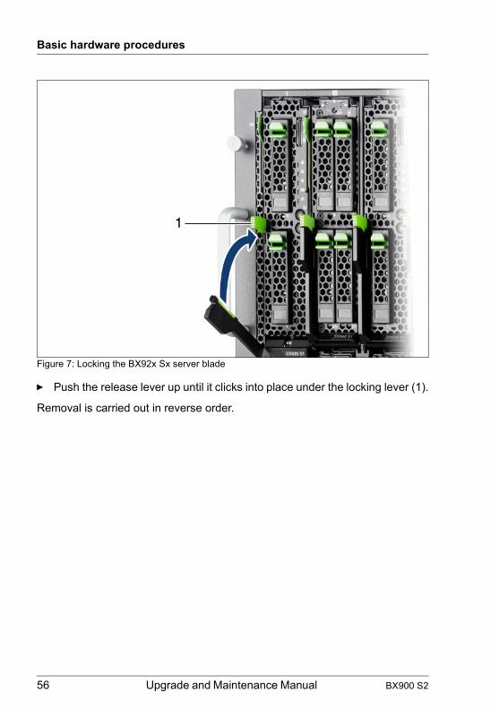
Basic hardware procedures
© c
ogni
tas.
Ges
ells
chft
für T
echn
ik-D
okum
enta
tion
mbH
201
1 P
fad:
C:\P
rogr
amm
e\FC
T\tim
_app
\tim
_loc
al\w
ork\
WA
LTE
R\O
BJ_
DO
KU
-136
54-0
01.fm
Figure 7: Locking the BX92x Sx server blade
Ê Push the release lever up until it clicks into place under the locking lever (1).
Removal is carried out in reverse order.
1
56 Upgrade and Maintenance Manual BX900 S2

Basic hardware procedures
4.6.2 Installing a single height / double width Blade
The following describes how to install a BX960 S1 server blade. This server blade occupies 2 bays one upon the other in the BX900 S2 system unit.
Figure 8: Installing a BX960 S1 server blade
Ê Undo the locking mechanism of the release lever (1).
Ê Open the release lever (2).
Ê Push the server blade as far as possible into the empty slot (3).
1
2
3
BX900 S2 Upgrade and Maintenance Manual 57

Basic hardware procedures
© c
ogni
tas.
Ges
ells
chft
für T
echn
ik-D
okum
enta
tion
mbH
201
1 P
fad:
C:\P
rogr
amm
e\FC
T\tim
_app
\tim
_loc
al\w
ork\
WA
LTE
R\O
BJ_
DO
KU
-136
54-0
01.fm
Figure 9: Locking the BX960 S1 server blade
Ê Push the release lever up until it clicks into place under the locking lever (1).
Removal is carried out in reverse order.
1
58 Upgrade and Maintenance Manual BX900 S2
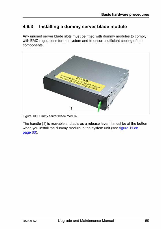
Basic hardware procedures
4.6.3 Installing a dummy server blade module
Any unused server blade slots must be fitted with dummy modules to comply with EMC regulations for the system and to ensure sufficient cooling of the components.
Figure 10: Dummy server blade module
The handle (1) is movable and acts as a release lever. It must be at the bottom when you install the dummy module in the system unit (see figure 11 on page 60).
1
BX900 S2 Upgrade and Maintenance Manual 59
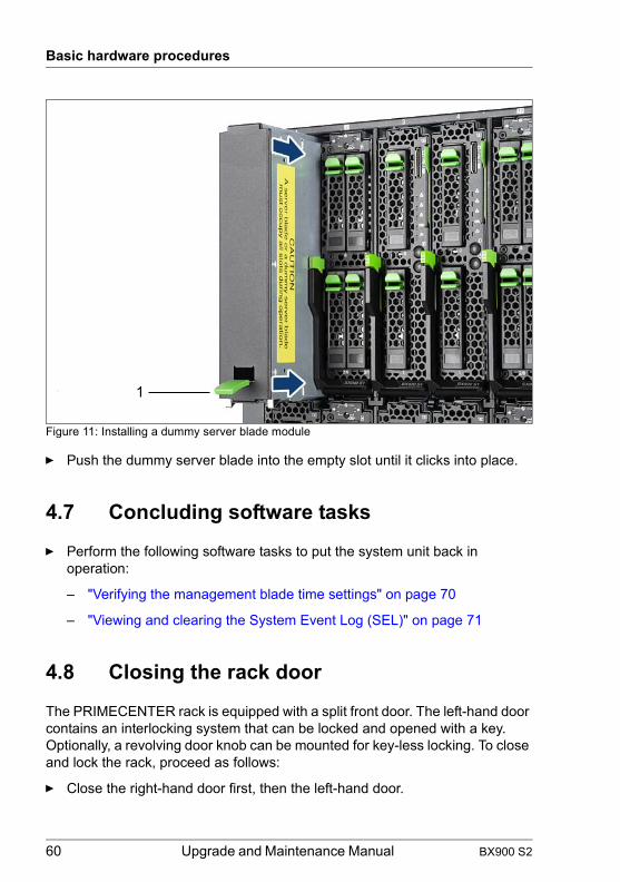
Basic hardware procedures
© c
ogni
tas.
Ges
ells
chft
für T
echn
ik-D
okum
enta
tion
mbH
201
1 P
fad:
C:\P
rogr
amm
e\FC
T\tim
_app
\tim
_loc
al\w
ork\
WA
LTE
R\O
BJ_
DO
KU
-136
54-0
01.fm
Figure 11: Installing a dummy server blade module
Ê Push the dummy server blade into the empty slot until it clicks into place.
4.7 Concluding software tasks
Ê Perform the following software tasks to put the system unit back in operation:
– "Verifying the management blade time settings" on page 70
– "Viewing and clearing the System Event Log (SEL)" on page 71
4.8 Closing the rack door
The PRIMECENTER rack is equipped with a split front door. The left-hand door contains an interlocking system that can be locked and opened with a key. Optionally, a revolving door knob can be mounted for key-less locking. To close and lock the rack, proceed as follows:
Ê Close the right-hand door first, then the left-hand door.
1
60 Upgrade and Maintenance Manual BX900 S2

Basic hardware procedures
Ê Insert and turn the key clockwise by 180 degrees.If applicable, turn the door knob clockwise by 180 degrees.
I For further information, refer to the "PRIMECENTER Rack System" assembly guide available online at http://manuals.ts.fujitsu.com or from the ServerView Suite DVD 2 supplied with your PRIMERGY server.
BX900 S2 Upgrade and Maintenance Manual 61

Basic hardware procedures
© c
ogni
tas.
Ges
ells
chft
für T
echn
ik-D
okum
enta
tion
mbH
201
1 P
fad:
C:\P
rogr
amm
e\FC
T\tim
_app
\tim
_loc
al\w
ork\
WA
LTE
R\O
BJ_
DO
KU
-136
54-0
01.fm
62 Upgrade and Maintenance Manual BX900 S2

5 Basic software procedures
5.1 Starting the maintenance task
5.1.1 Switching on the ID indicator
When working in a datacenter environment, switch on the ID indicator on the front and rear of the system unit for easy identification.
I For further information, refer to section "Locating the defective system unit" on page 45.
Using the ID button on the Local Service Display
Ê Press the ID button on the Local Service Display to switch on the ID indicators.
I For further information, refer to section "Control elements on the Local Service Display" on page 180.
Using the ID button on the management blade
Ê Press the ID button on the management blade to switch on the ID indicators
I For further information, refer to section "Control elements and indicators on the management blade" on page 184.
Using management blade web interface
Ê In management blade web interface press the Locate button in the status frame to switch on the ID indicators.
Using ServerView Operations Manager
Ê In ServerView Operations Manager choose Single System View and press the Locate button in the title bar to switch on the ID indicators.
BX900 S2 Upgrade and Maintenance Manual 63

Basic software procedures
© c
ogni
tas.
Ges
ells
chft
für T
echn
ik-D
okum
enta
tion
mbH
201
1 P
fad:
C:\P
rogr
amm
e\FC
T\tim
_app
\tim
_loc
al\w
ork\
WA
LTE
R\O
BJ_
DO
KU
-136
55-0
01.fm
5.1.2 Saving / Restoring management blade settings
Non-default management blade settings are automatically stored from the management blade NVRAM to the Chassis ID EPROM which is located in the front docking board. To avoid the loss of management blade settings when replacing the front docking board, you must create a backup copy of the management blade settings.
After replacing the front docking board, you must to restore the backup copy of the management blade settings to the new front docking board.
Saving management blade settings
Ê Enter the management blade web interface, see section "Accessing the management blade web interface" on page 44.
Ê Select the System – Management Blades – Management Blade-x menu for the management blade with the backup medium.
Ê Open the Backup/Restoration tab.
Ê In the Backup Configuration box select the backup medium.
– Select Local File to store the backup file in the file system of the field service terminal.
I The filename of the backup file will be automatically generated using date and time the format mmbyyyymmtthhmmss.bin
– Select USB if the backup file is stored in a USB memory stick.
I This option is only displayed if a USB memory stick is connected to the management blade.
Ê Click the Backup button to start the backup process.
If the backup process has been finished successfully, the following message will be displayed in the Memory/USB Backup Status field.
MMB base configuration backup ok
Restoring management blade settings
Ê Enter the management blade web interface, see section "Accessing the management blade web interface" on page 44.
Ê Open the System – Management Blades – Management Blade-x menu for the management blade which is connected with the backup medium.
64 Upgrade and Maintenance Manual BX900 S2

Basic software procedures
Ê Enter the Backup/Restoration tab.
Ê In the Restore Configuration box select the backup media.
– Select USB, if the backup copy is stored on a USB memory stick plugged in to the management blade.
– Select Local File, if the backup copy is saved in the file system of the field service terminal.
Ê Select the backup file and click the Restore button.
If the restore process has been finished successfully, the following message will be displayed in the Memory/USB Backup Status field.
MMB base configuration restore ok
BX900 S2 Upgrade and Maintenance Manual 65

Basic software procedures
© c
ogni
tas.
Ges
ells
chft
für T
echn
ik-D
okum
enta
tion
mbH
201
1 P
fad:
C:\P
rogr
amm
e\FC
T\tim
_app
\tim
_loc
al\w
ork\
WA
LTE
R\O
BJ_
DO
KU
-136
55-0
01.fm
5.2 Completing the maintenance task
5.2.1 Updating / recovering the management blade firmware
The procedures described in this section apply to different scenarios.
Updating the management blade firmware via management blade web interface
– Two management blades are installed in the system unit and the firmware of both must be updated.
– One management blade is installed in the system unit and works well. The firmware must be updated to a later version to match new requirements.
Updating the management blade firmware via recovery flash
– Two management blades are installed in the system unit and the slave management blade has been replaced. The firmware of this management blade must be updated to the same firmware version as of the master.
– The only one management blade of a system unit has been replaced. The management blade firmware must be updated to the same or a later firmware version as of the old management blade.
The latest firmware versions are available from the Fujitsu support internet pages at:
http://ts.fujitsu.com/support/ (EMEA market)http://jp.fujitsu.com/platform/server/primergy/downloads/ (Japanese market)
I Fujitsu does not assume responsibility for any damage done to the server or for the loss of any data resulting from firmware updates.
5.2.1.1 Looking up the management blade firmware version
Ê Open the Components – System – Management Blades – Management Blade-x menu for the desired management blade.
The firmware version is displayed in the Blade Information tab.
66 Upgrade and Maintenance Manual BX900 S2

Basic software procedures
5.2.1.2 Updating the management blade firmware via management blade web interface
TFTP update procedure
Ê Enter the management blade web interface, see section "Accessing the management blade web interface" on page 44.
Ê Open the Information / Operation – Operation – Firmware Update menu.
Ê Open the Management Blade tab.
Ê In the Management Blade Firmware TFTP Update box enter the TFTP IPv4 or IPv6 address of the TFTP server and the pathname of the TFTP firmware file.
Ê In the Enable TFTP Update check box select the update mode:
– Select Single MMB firmware update enable to update the firmware of the master management blade.
– Select Dual MMB firmware update enable to update the firmware of both management blades.
Ê Click the Apply button to start the update process.
File procedure
Ê Enter the management blade web interface, see section "Accessing the management blade web interface" on page 44.
Ê Open the Information / Operation – Operation – Firmware Update menu.
Ê Open the Management Blade tab.
Ê In the Management Blade Firmware File Update box click the Search button to open a file dialog box to select the firmware image file from a local device.
Ê In the Enable File Update field select the update mode:
– Select Single MMB firmware update enable to update the firmware of the master management blade.
– Select Dual MMB firmware update enable to update the firmware of both management blades.
Ê Click the Apply button to start the update process.
I For the Japanese market, follow the instructions provided separately.
BX900 S2 Upgrade and Maintenance Manual 67

Basic software procedures
© c
ogni
tas.
Ges
ells
chft
für T
echn
ik-D
okum
enta
tion
mbH
201
1 P
fad:
C:\P
rogr
amm
e\FC
T\tim
_app
\tim
_loc
al\w
ork\
WA
LTE
R\O
BJ_
DO
KU
-136
55-0
01.fm
5.2.1.3 Updating the management blade firmware via recovery flash
Ê Open the management blade, as described in section "Opening the management blade" on page 149.
Ê Enter recovery mode using the DIP switch, see section "Management Blade Settings" on page 204.
Ê Close the management blade in the opposite order to that described in section "Opening the management blade" on page 149.
Ê Install management blade into the system unit, "Installing the management blade" on page 145.
Ê Connect the FST to the serial port of the management blade, see section "Connectors on the management blade" on page 183.
Ê Open a Hyperterminal session using the following parameters:
The welcome screen of the recovery console menu is displayed.
⎜ (1) Upgrade Firmware from Network ⎥⎜ (2) Network Parameters ⎥⎜ ---------------------------------------- ⎥⎜ Choose: 2 ⎥⎜ ⎥⎜ ⎥⎜ ⎥
Figure 12: Recovery console menu
Ê Enter 2 to open the Network Parameters menu.
Ê Select 1 to set the IP Address of the management blade management LAN port.
Ê Enter 2 to set the IP address of the TFTP server.
Ê Enter 3 to set the gateway address of management LAN port.
Bits per second 115200Data bits 8Parity NoneStop bits 1Flow control Xon/Xoff
Table 4: COM parameters
68 Upgrade and Maintenance Manual BX900 S2

Basic software procedures
Ê Enter 4 to set the gateway address of subnet mask.
Ê Enter 5 to set the TFTP file name.
Ê Enter 0 to leave the Network Paramenters menu.
Ê Connect the FST to the service LAN connector of the management blade, see pos. #4 or 5 in "Connectors on the management blade" on page 183.
I The FST must be on the same LAN with the same subnet as the service LAN port.
Ê Enter 1 to open the Upgrade Firmware from Network menu.
Ê Open the Management Blade Update Enable menu.
Ê Select Single MMB firmware update enable to start the firmware update process.
Wait until the firmware update is completed.
Ê Remove the management blade from the system unit. This is done in the same way as described in section "Removing a single-width connection blade" on page 116.
Ê Open the management blade, as described in section "Opening the management blade" on page 149 and set the Recovery Mode DIP switch OFF, see "Management Blade Settings" on page 204.
Ê Close the management blade in the opposite order to that described in section "Opening the management blade" on page 149.
Ê Reinstall the management blade into the system unit, "Installing the management blade" on page 145.
BX900 S2 Upgrade and Maintenance Manual 69

Basic software procedures
© c
ogni
tas.
Ges
ells
chft
für T
echn
ik-D
okum
enta
tion
mbH
201
1 P
fad:
C:\P
rogr
amm
e\FC
T\tim
_app
\tim
_loc
al\w
ork\
WA
LTE
R\O
BJ_
DO
KU
-136
55-0
01.fm
5.2.2 Verifying the management blade time settings
After a management blade has been replaced, you must check the system time settings.
System unit with one management blade installed
Ê After replacing the management blade, ask the system administrator whether the RTC or UTC time standard is to be used as system time.
I If the system time (RTC) is set to UTC, the SEL (System Event Log) time stamps may differ from the local time.
Ê Enter the management blade web interface, see section "Accessing the management blade web interface" on page 44.
Ê Select the Settings – System Unit – Date/Time menu.
Ê Under System Time and System Date specify the correct time and date.
I By default, the system time set in the management blade is RTC (Real Time Clock) local time. If your IT infrastructure relies on universally accepted time standards, set the System Time to UTC (Universal Time, Coordinated) instead. Greenwich Mean Time (GMT) can be considered equivalent to UTC.
Ê Save your changes and exit the management blade web interface.
System unit with two management blades installed
After replacing the slave management blade, the slave management blade inherits the time settings from the master management blade. Nevertheless time settings should be checked.
Ê Enter the management blade web interface.
Ê Select the Settings – System Unit – Date/Time menu.
Ê Under System Time and System Date specify the correct time and date.
Ê Save your changes and exit the management blade web interface.
I For detailed information on how to access the management blade web interface and modify settings, refer to the "PRIMERGY BX900 Blade Server Systems ServerView Management Blade S1 User Interface Description".
70 Upgrade and Maintenance Manual BX900 S2

Basic software procedures
5.2.3 Viewing and clearing the System Event Log (SEL)
5.2.3.1 Viewing the SEL
You can view the System Event Log (SEL) of the management blades and server blades using the management blade web interface and ServerView Operations Manager frontend:
Viewing the SEL using the management blade web interface
Ê Enter the management blade web interface, see section "Accessing the management blade web interface" on page 44.
Ê Select the Components – System – Management Blades – Management Blade-x menu or the Components – System – Server Blades – Server Blade-x menu and open the Event Log tab.
Ê In the Event Log Content box the SEL is being displayed.
Ê In the Event Log Filter box select the message type(s) you want to display:
– All events– Informational– Minor– Major– Critical
Viewing the SEL in ServerView Operations Manager
Ê In ServerView Operations Manager Single System View select Maintenance from the Information / Operation menu.
Ê Under Maintenance select System Event Log.
Ê Select the message type(s) you want to display:
– Critical events– Major events– Minor events– Informational events
I For detailed information on how to view and sort the SEL using ServerView Operations Manager, refer to the "ServerView Operations Manager - Server Management" user guide.
BX900 S2 Upgrade and Maintenance Manual 71

Basic software procedures
© c
ogni
tas.
Ges
ells
chft
für T
echn
ik-D
okum
enta
tion
mbH
201
1 P
fad:
C:\P
rogr
amm
e\FC
T\tim
_app
\tim
_loc
al\w
ork\
WA
LTE
R\O
BJ_
DO
KU
-136
55-0
01.fm
5.2.3.2 Clearing the SEL
You can clear the System Event Log (SEL) using the management blade web interface:
Ê Enter the management blade web interface, see section "Accessing the management blade web interface" on page 44.
Ê Select the Components – System – Management Blades – Management Blade-x menu or the Components – System – Server Blades – Server Blade-x menu and open the Event Log tab.
Ê In the Event Log Filter box click Clear All Entries to clear the SEL.
72 Upgrade and Maintenance Manual BX900 S2

Basic software procedures
5.2.4 Checking management master/slave behavior
I This task applies, if two management blades are installed in the system unit.
When a management blade is replaced, the new one takes on the slave role. To verify whether the new management blade is OK, you must switch/change the master/slave assignment and verify the settings of the master.
I Switching/changing the master/slave roles of the management blades is a noisy process (approx. 78 dB), as it causes the fans to briefly run at maximum power.
Ê Open the Components – System – Management Blades – Management Blade-x menu for the slave management blade.
Ê Open the Configuration tab.
Ê In the Switch Management Role box, click the Switch Role button.
Ê Click the Confirm Switch Role button.
The following message will be displayed:
Changed role of Management Blade-x by user operation.
Ê Open the Information tab.
Ê Verify the management blade settings.
I If you are constantly switching/changing the master/slave assignment, make sure you wait at least three minutes between each switching/changing, otherwise the state of the server blades cannot be determined. If this occurs, reset both master and slave with the reset button.
BX900 S2 Upgrade and Maintenance Manual 73

Basic software procedures
© c
ogni
tas.
Ges
ells
chft
für T
echn
ik-D
okum
enta
tion
mbH
201
1 P
fad:
C:\P
rogr
amm
e\FC
T\tim
_app
\tim
_loc
al\w
ork\
WA
LTE
R\O
BJ_
DO
KU
-136
55-0
01.fm
5.2.5 Updating the connection blade firmware
When replacing a connection blade make sure that the firmware version of the new connection blade matches the firmware version of the old one.
Looking up the connection blade firmware version
Ê Login to the management blade web interface, see section "Accessing the management blade web interface" on page 44.
Ê Open the Components – System – Connection Blades – Connection Blade-x menu for the desired connection blade.
The firmware version is displayed in the Blade Information tab.
Updating the connection blade firmware
Ê Open the System – Connection Blades – Connection Blade-x menu for the desired connection blade.
Ê Open the Blade Information tab.
Ê Click the Administrative URL.
The file manager obtains access to a the connection blade web interface. For detailed information, please refer to the relevant connection blade manual.
I For the Japanese market, follow the instructions provided separately.
74 Upgrade and Maintenance Manual BX900 S2

Basic software procedures
5.2.6 Configuring connection blade settings
Configuring out-of-band settings of a connection blade
Ê Login to the management blade web interface, see section "Accessing the management blade web interface" on page 44.
Ê Open the Components – System – Connection Blades – Connection Blade-x menu for the desired connection blade.
Ê Open the Configuration tab.
Ê Edit the configuration settings. For information on the configuration parameters, please refer to the Help – On Page function of the management blade web interface.
Configuring enhanced connection blade settings
Ê If applicable, login to the management blade web interface, see section "Accessing the management blade web interface" on page 44.
Ê Open the System – Connection Blades – Connection Blade-x menu for the desired connection blade.
Ê Open the Blade Information tab.
Ê Click the Administrative URL.
The file manager obtains access to a the connection blade web interface. For detailed information, please refer to the relevant connection blade manual.
BX900 S2 Upgrade and Maintenance Manual 75

Basic software procedures
© c
ogni
tas.
Ges
ells
chft
für T
echn
ik-D
okum
enta
tion
mbH
201
1 P
fad:
C:\P
rogr
amm
e\FC
T\tim
_app
\tim
_loc
al\w
ork\
WA
LTE
R\O
BJ_
DO
KU
-136
55-0
01.fm
5.2.7 Saving connection blade settings
After replacing and configuring a connection blade you must create a backup copy of the connection blade settings.
Saving out-of-band connection blade settings
Perform the following steps to create a backup copy of the out-of-band configuration data of a connection blade.
Ê If not done yet, login to the management blade web interface, see section "Accessing the management blade web interface" on page 44.
Ê Open the System – Connection Blades – Connection Blade-x menu for the desired connection blade.
Ê Open the Backup/Restoration tab.
Ê In the Backup Configuration box of the Connection Blade Out-Of-Band Configuration frame select the backup medium.
– Select Memory to store the backup file in the management blade memory.
– Select USB to store the backup file in a USB memory stick.
I This option is only displayed if a USB memory stick is connected to the management blade.
– Select Local File to store the backup file in the file system of the field service terminal.
I The filename of the backup copy will be automatically generated consisting of an identification tag and the current date and time.
Ê Click the Backup button.
Saving enhanced connection blade settings
Perform the following steps to create a backup copy of the enhanced configuration data of a connection blade.
Ê If not done yet, login to the management blade web interface, see section "Accessing the management blade web interface" on page 44.
Ê Open the System – Connection Blades – Connection Blade-x menu for the desired connection blade.
Ê Open the Backup/Restoration tab.
76 Upgrade and Maintenance Manual BX900 S2
Basic software procedures
Ê In the Backup/Restoration Configuration box of the Connection Blade Configuration click the Apply button.
The file manager obtains access to a web site of the connection blade where the current configuration of the connection blade can be saved or restored. For detailed information, please refer to the relevant connection blade manual.
BX900 S2 Upgrade and Maintenance Manual 77

Basic software procedures
© c
ogni
tas.
Ges
ells
chft
für T
echn
ik-D
okum
enta
tion
mbH
201
1 P
fad:
C:\P
rogr
amm
e\FC
T\tim
_app
\tim
_loc
al\w
ork\
WA
LTE
R\O
BJ_
DO
KU
-136
55-0
01.fm
5.2.8 Restoring connection blade settings
Restoring out-of-band connection blade settings
Perform the following steps to restore a backup copy of out-of-band connection blade settings.
Ê If not done yet, login to the management blade web interface, see section "Accessing the management blade web interface" on page 44.
Ê Open the System – Connection Blades – Connection Blade-x menu for the desired connection blade.
Ê Open the Backup/Restoration tab.
Ê In the Restore Configuration box of the Connection Blade Out-Of-Band Configuration frame select the backup medium.
– Select Memory, if the backup file is stored in the management blade memory.
– Select USB if the backup file is stored in a USB memory stick.
I This option is only displayed if a USB memory stick is connected to the management blade.
– Select Local File to store the backup file in the file system of the field service terminal.
Ê Select the backup file.
Ê Click the Restore button.
Restoring enhanced connection blade settings
Perform the following steps to restore the backup copy of the enhanced configuration data of a connection blade.
Ê If not done yet, login to the management blade web interface, see section "Accessing the management blade web interface" on page 44.
Ê Open the System – Connection Blades – Connection Blade-x menu for the desired connection blade.
Ê Open the Backup/Restoration tab.
Ê In the Backup/Restoration Configuration box of the Connection Blade Configuration click the Apply button.
78 Upgrade and Maintenance Manual BX900 S2

Basic software procedures
The file manager obtains access to a web site of the connection blade where the current configuration of the connection blade can be saved or restored. For detailed information, please refer to the relevant connection blade manual.
BX900 S2 Upgrade and Maintenance Manual 79

Basic software procedures
© c
ogni
tas.
Ges
ells
chft
für T
echn
ik-D
okum
enta
tion
mbH
201
1 P
fad:
C:\P
rogr
amm
e\FC
T\tim
_app
\tim
_loc
al\w
ork\
WA
LTE
R\O
BJ_
DO
KU
-136
55-0
01.fm
5.2.9 Verifying power consumption
I This task applies only, if a PSU must be replaced, which has not failed completely.
Ê Login to the management blade web interface, see section "Accessing the management blade web interface" on page 44.
Ê Open the Information/Operation – Operation – Power Management menu, select the Configuration tab and scroll to the Power Consumption Options box.
– If a redundancy mode is selected in the Redundancy pull down (for example 3+1) you can replace the PSU with no problems.
– If No Redundancy is selected in the Redundancy pull down and if the Remaining Output Power is less than ca. 3200 W, you must shut down some server blades before replacing the PSU.
I The Remaining Output Power value is displayed in the status frame of the management blade web interface.
80 Upgrade and Maintenance Manual BX900 S2

Basic software procedures
5.2.10 Configuring power supply redundancy
Ê Login to the management blade web interface, see section "Accessing the management blade web interface" on page 44.
Ê Open the Information/Operation – Operation – Power Management menu, select the Configuration tab and scroll to the Power Consumption Options box.
Ê Select the redundancy mode In the Redundancy check box.
I How many PSUs need to be installed to provide power supply redundancy depends on the number of server blades, see section "Power supply redundancy" on page 86.
For detailed information on power management, refer to the "PRIMERGY BX900 Blade Server Systems ServerView Management Blade S1 User Interface Description".
BX900 S2 Upgrade and Maintenance Manual 81

Basic software procedures
© c
ogni
tas.
Ges
ells
chft
für T
echn
ik-D
okum
enta
tion
mbH
201
1 P
fad:
C:\P
rogr
amm
e\FC
T\tim
_app
\tim
_loc
al\w
ork\
WA
LTE
R\O
BJ_
DO
KU
-136
55-0
01.fm
5.2.11 Using the Chassis ID Prom Tool
The Chassis ID EPROM located on the front docking board contains system information like system unit name and model, housing type, serial number and manufacturing data.
In order to integrate your system into the ServerView management environment, system data needs to be complete and correct.
After replacing the front docking board, system information has to be entered using the ChassisId_Prom Tool. The tool and further instructions are available to maintenance personnel from the Fujitsu Technology Solutions Extranet:
http://partners.ts.fujitsu.com/com/service/intelservers/tools
I For the Japanese market, follow the instructions provided separately.
82 Upgrade and Maintenance Manual BX900 S2

Basic software procedures
5.2.12 Switching off the ID indicator
Press the ID button on the Local Service Display or on the management blade or use the management blade web interface to switch off the ID indicator after the maintenance task has been concluded successfully.
I For further information, refer to section "Locating the defective system unit" on page 45.
Using the ID button on the Local Service Display
Ê Press the ID button on the Local Service Display to switch on the ID indicators.
I For further information, refer to section "Control elements on the Local Service Display" on page 180.
Using the ID button on the management blade
Ê Press the ID button on the management blade to switch on the ID indicators.
I For further information, refer to section "Control elements and indicators on the management blade" on page 184.
Using management blade web interface
Ê In management blade web interface press the Locate button in the status frame to switch on the ID indicators.
Using ServerView Operations Manager
Ê In ServerView Operations Manager choose Single System View and press the Locate button in the title bar to switch on the ID indicators.
BX900 S2 Upgrade and Maintenance Manual 83

Basic software procedures
© c
ogni
tas.
Ges
ells
chft
für T
echn
ik-D
okum
enta
tion
mbH
201
1 P
fad:
C:\P
rogr
amm
e\FC
T\tim
_app
\tim
_loc
al\w
ork\
WA
LTE
R\O
BJ_
DO
KU
-136
55-0
01.fm
84 Upgrade and Maintenance Manual BX900 S2
6 Power supplyThis chapter provides information on how to replace the power supply unit (PSU).
V CAUTION!
● A combination of standard PSUs and high efficiency PSUs in one BX900 S2 system unit is not allowed.
● The system unit supports a mains voltage in the range of 100 VAC to 240 VAC. You may only operate the server if its rated voltage range corresponds to the local mains voltage.
Safety notes
V CAUTION!
● Do not disassemble the PSU. Doing so may cause electric shock.
● Areas around the PSU may remain extremely hot after shutdown. After shutting down the server, wait for hot components to cool down before removing the PSU.
● The PSU is heavy, so handle it carefully. If you drop it by mistake, injuries may result.
● For further safety information, please refer to chapter "Important information" on page 29.
BX900 S2 Upgrade and Maintenance Manual 85

Power supply
© c
ogni
tas.
Ges
ells
chft
für T
echn
ik-D
okum
enta
tion
mbH
201
1 P
fad:
C:\P
rogr
amm
e\FC
T\tim
_app
\tim
_loc
al\w
ork\
WA
LTE
R\O
BJ_
DO
KU
-136
56-0
01.fm
6.1 Basic information
The BX900 S2 system unit has 6 bays for hot-plug PSUs (PSU 1-6). There are two types of PSUs available, standard PSU and High Efficiency PSU (hereinafter referred to as HE PSU), see the "PRIMERGY BX900 S2 Blade Server System Unit Operating Manual".
I The information in this section applies to both standard PSUs and high efficiency PSUs.
6.1.1 Power supply redundancy
Figure 13: Numbering of the PSU bays
In the minimum configuration, bays PSU 2, PSU 3 and PSU 6 are fitted with PSUs. The remaining bays are free.
Depending on the system unit configuration, the remaining bays must be fitted with further PSUs or with fan modules. Make sure you observe the following order: PSU 5 – PSU 1 – PSU 4. The required number of PSUs and fan modules
PSU 1 PSU 2 PSU 3
PSU 4 PSU 5 PSU 6
86 Upgrade and Maintenance Manual BX900 S2

Power supply
depends on the configuration, number and types of installed server blades, the available mains voltage and the redundant power supply requirements. The following table shows the mutual dependencies.
I The numbers of installed server blades in the following table are only approximate values. For further information regarding Power Consumption and Power Efficiency please refer to
http://ts.fujitsu.com/products/standard_servers/e_efficient.html(for the EMEA market)
http://jp.fujitsu.com/platform/server/primergy/technical/(for the Japanese market)
PSU 2685 W / 100 V AC PSU 2685 W / 230 V AC
Number of installed Max. number Max. number
PSU FanMax.
Dual Server Blades
PSU redundancy
Max. Dual Server
Blades
PSU redundancy
3 0 7 2+11
1 2+1 power supply redundancy is possible. In this case you must check the Power Management menu of the management blade web interface to ensure that sufficient power supply is available.
3
0
7 3+0
7
3+01 10
2 14
3 18
4
0
10 4+0
10
3+11 14
2 18
50
165+0
143+2
1 18
60 5+1 18
3+30 18 6+0 18
Table 5: Fitting rules for PSUs, fan modules and server blades
BX900 S2 Upgrade and Maintenance Manual 87

Power supply
© c
ogni
tas.
Ges
ells
chft
für T
echn
ik-D
okum
enta
tion
mbH
201
1 P
fad:
C:\P
rogr
amm
e\FC
T\tim
_app
\tim
_loc
al\w
ork\
WA
LTE
R\O
BJ_
DO
KU
-136
56-0
01.fm
V CAUTION!
If a PSU fails in a non-redundant configuration of PSUs, and the remaining PSUs do not provide sufficient power, the system unit is shut down immediately.
I Make sure that the individual PSUs are connected to different phases. This ensures additional phase redundancy for high availability configurations. If only one phase fails, the PSUs connected to the other phases remain operational. You can achieve full phase redundancy with three PSUs. If more PSUs are installed, up to two PSUs must be connected to each individual phase (for information on the electrical connections, see the technical manual for the PRIMECENTER rack).
Phase redundancy is possible in regions where the single phase provides 200 - 240V; in other regions with lower single-phase voltage, two phases have to be coupled, which means that full phase redundancy is not possible.
6.1.2 Cooling requirements
The BX900 S2 system unit is divided into 6 cooling zones. To achieve optimum cooling of all components, the 6 cooling zones on the front and back of the system unit must be fitted equally.
The following examples show how the various configurations of slots for PSUs and fan modules as well as for server blades and/or storage blades should be fitted.
V CAUTION!
Any unused server blade slots must be fitted with dummy modules, see "Installing a dummy server blade module" on page 59.
88 Upgrade and Maintenance Manual BX900 S2

Power supply
Configuration with three power supply units (minimum configuration)
Zone 5 Zone 3 Zone 1 Zone 1 Zone 3 Zone 5
PSU 1 PSU 2 PSU 3 1 2 3 4 17 5 6 7 8
PSU 4 PSU 5 PSU 6 9 10 11 12 18 13 14 15 16
Zone 6 Zone 4 Zone 2 Zone 2 Zone 4 Zone 6
BX900 S2 Upgrade and Maintenance Manual 89
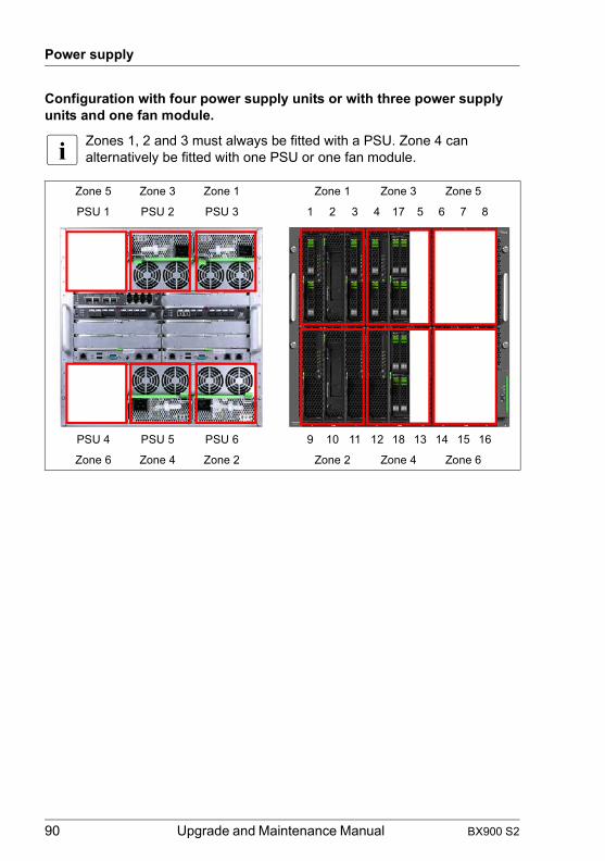
Power supply
© c
ogni
tas.
Ges
ells
chft
für T
echn
ik-D
okum
enta
tion
mbH
201
1 P
fad:
C:\P
rogr
amm
e\FC
T\tim
_app
\tim
_loc
al\w
ork\
WA
LTE
R\O
BJ_
DO
KU
-136
56-0
01.fm
Configuration with four power supply units or with three power supply units and one fan module.
I Zones 1, 2 and 3 must always be fitted with a PSU. Zone 4 can alternatively be fitted with one PSU or one fan module.
Zone 5 Zone 3 Zone 1 Zone 1 Zone 3 Zone 5
PSU 1 PSU 2 PSU 3 1 2 3 4 17 5 6 7 8
PSU 4 PSU 5 PSU 6 9 10 11 12 18 13 14 15 16
Zone 6 Zone 4 Zone 2 Zone 2 Zone 4 Zone 6
90 Upgrade and Maintenance Manual BX900 S2

Power supply
Configuration with five power supply units or with four power supply units and one fan module or with three power supply units and two fan modules.
I Zones 1, 2 and 3 must always be fitted with a PSU. Zones 4 and 5 can be fitted with either PSUs or fan modules.
Zone 5 Zone 3 Zone 1 Zone 1 Zone 3 Zone 5
PSU 1 PSU 2 PSU 3 1 2 3 4 17 5 6 7 8
PSU 4 PSU 5 PSU 6 9 10 11 12 18 13 14 15 16
Zone 6 Zone 4 Zone 2 Zone 2 Zone 4 Zone 6
BX900 S2 Upgrade and Maintenance Manual 91
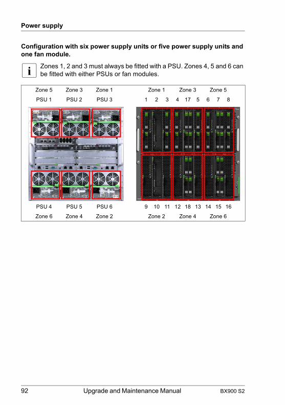
Power supply
© c
ogni
tas.
Ges
ells
chft
für T
echn
ik-D
okum
enta
tion
mbH
201
1 P
fad:
C:\P
rogr
amm
e\FC
T\tim
_app
\tim
_loc
al\w
ork\
WA
LTE
R\O
BJ_
DO
KU
-136
56-0
01.fm
Configuration with six power supply units or five power supply units and one fan module.
I Zones 1, 2 and 3 must always be fitted with a PSU. Zones 4, 5 and 6 can be fitted with either PSUs or fan modules.
Zone 5 Zone 3 Zone 1 Zone 1 Zone 3 Zone 5
PSU 1 PSU 2 PSU 3 1 2 3 4 17 5 6 7 8
PSU 4 PSU 5 PSU 6 9 10 11 12 18 13 14 15 16
Zone 6 Zone 4 Zone 2 Zone 2 Zone 4 Zone 6
92 Upgrade and Maintenance Manual BX900 S2

Power supply
6.2 Installing a power supply unit
6.2.1 Required tools
● Preliminary and concluding steps: tool-less
● Replacing the fan module: tool-less
6.2.2 Preliminary steps
Before installing a power supply unit (PSU), perform the following steps:
Ê If applicable, open the rack door as described in section "Opening the rack door" on page 48.
Ê Locate the desired system unit as described in section "Determining the error class" on page 45.
Ê Determine the mounting bay of the new PSU using the information in section "Cooling requirements" on page 88.
Customer Replaceable Units (CRU)
average hardware task duration: 5 minutes
average software task duration: 5 minutes
BX900 S2 Upgrade and Maintenance Manual 93

Power supply
© c
ogni
tas.
Ges
ells
chft
für T
echn
ik-D
okum
enta
tion
mbH
201
1 P
fad:
C:\P
rogr
amm
e\FC
T\tim
_app
\tim
_loc
al\w
ork\
WA
LTE
R\O
BJ_
DO
KU
-136
56-0
01.fm
6.2.3 Installing a power supply unit
Figure 14: Open release lever
Ê Open the release lever (1).
Ê Push the PSU as far as possible into the empty bay (2).
Ê Swivel the release lever down until it clicks into place under the locking lever.
6.2.4 Concluding steps
Perform the following procedures to complete the task:
Ê Connect the AC power cord to the PSU and secure it with a cable tie as described in section "Connecting the system unit to the mains" on page 50.
Ê If applicable, close the rack door as described in section "Closing the rack door" on page 60.
Ê Configure PSU redundancy as described in section "Configuring power supply redundancy" on page 81.
94 Upgrade and Maintenance Manual BX900 S2

Power supply
6.3 Replacing a power supply unit
6.3.1 Required tools
● Preliminary and concluding steps: tool-less
● Replacing the fan module: tool-less
6.3.2 Preliminary steps
Before replacing the power supply unit (PSU), perform the following steps:
Ê Check the power supply redundancy configuration as described in section "Verifying power consumption" on page 80.
Ê If applicable, open the rack door as described in section "Opening the rack door" on page 48.
Ê Locate the desired system unit as described in section "Determining the error class" on page 45.
Ê Locate the defective PSU as described in section "Locating the defective component" on page 48.
Ê Remove the AC power cord from the cable tie and disconnect it from the system as described in section "Disconnecting the power cords" on page 49.
Customer Replaceable Units (CRU)
average hardware task duration: 5 minutes
average software task duration: 10 minutes
BX900 S2 Upgrade and Maintenance Manual 95

Power supply
© c
ogni
tas.
Ges
ells
chft
für T
echn
ik-D
okum
enta
tion
mbH
201
1 P
fad:
C:\P
rogr
amm
e\FC
T\tim
_app
\tim
_loc
al\w
ork\
WA
LTE
R\O
BJ_
DO
KU
-136
56-0
01.fm
6.3.3 Removing the power supply unit
Figure 15: Open release lever
Ê Unlock the locking lever (1) and open the release lever (2).
Figure 16: Removing the PSU
Ê Pull the PSU out of its bay.
2
1
96 Upgrade and Maintenance Manual BX900 S2

Power supply
6.3.4 Concluding steps
Perform the following procedures to complete the task:
Ê Install the new PSU as described in section "Installing a power supply unit" on page 94.
Ê Connect the AC power cord to the PSU and secure it with a cable tie as described in section "Connecting the system unit to the mains" on page 50.
Ê If applicable, close the rack door as described in section "Closing the rack door" on page 60.
BX900 S2 Upgrade and Maintenance Manual 97

Power supply
© c
ogni
tas.
Ges
ells
chft
für T
echn
ik-D
okum
enta
tion
mbH
201
1 P
fad:
C:\P
rogr
amm
e\FC
T\tim
_app
\tim
_loc
al\w
ork\
WA
LTE
R\O
BJ_
DO
KU
-136
56-0
01.fm
98 Upgrade and Maintenance Manual BX900 S2

7 Fan module and fan unitThis chapter provides information on how to replace a fan module and a fan unit.
Safety notes
V CAUTION!
Please refer to chapter "Important information" on page 29.
I Whether and how many fan modules need to be installed depends on the number of server blades installed and on the redundant power supply requirements, see section "Cooling requirements" on page 88.
7.1 Replacing a fan module
7.1.1 Required tools
● Preliminary and concluding steps: tool-less
● Replacing the fan module: tool-less
7.1.2 Preliminary steps
Before replacing the fan module, perform the following steps:
Ê If applicable, open the rack door as described in section "Opening the rack door" on page 48.
Customer Replaceable Units (CRU)
average hardware task duration: 5 minutes
average software task duration: 10 minutes
BX900 S2 Upgrade and Maintenance Manual 99

Fan module and fan unit
© c
ogni
tas.
Ges
ells
chft
für T
echn
ik-D
okum
enta
tion
mbH
201
1 P
fad:
C:\P
rogr
amm
e\FC
T\tim
_app
\tim
_loc
al\w
ork\
WA
LTE
R\O
BJ_
DO
KU
-136
58-0
01.fm
Ê Locate the desired system unit as described in section "Determining the error class" on page 45.
Ê Locate the defective fan module as described in section "Locating the defective component" on page 48.
7.1.3 Removing the fan module
Fan modules are removed in the same way as PSUs, see "Removing the power supply unit" on page 96.
7.1.4 Installing the fan module
Rear fan module are installed in the same way as PSUs, see "Installing a power supply unit" on page 94.
7.1.5 Concluding steps
Perform the following procedures to complete the task:
Ê If applicable, close the rack door as described in section "Closing the rack door" on page 60.
100 Upgrade and Maintenance Manual BX900 S2

Fan module and fan unit
7.2 Replacing a fan unit
PSUs and fan modules contain a fan unit on each of their front and rear sides. The mounting positions of the fan units are the same for PSUs and fan modules.
Figure 17: Fan units in a PSU
V CAUTION!
Do not install fan units of high efficiency PSUs in standard PSUs or in fan modules and otherwise! Fan units of high efficiency PSUs are not compatible with fan units of standard PSUs and fan modules.
7.2.1 Required tools
● Preliminary and concluding steps: tool-less
● Replacing the fan module: tool-less
Customer Replaceable Units (CRU)
average hardware task duration: 5 minutes
average software task duration: 10 minutes
BX900 S2 Upgrade and Maintenance Manual 101

Fan module and fan unit
© c
ogni
tas.
Ges
ells
chft
für T
echn
ik-D
okum
enta
tion
mbH
201
1 P
fad:
C:\P
rogr
amm
e\FC
T\tim
_app
\tim
_loc
al\w
ork\
WA
LTE
R\O
BJ_
DO
KU
-136
58-0
01.fm
7.2.2 Preliminary steps
Before replacing the fan module, perform the following steps:
Ê If applicable, open the rack door as described in section "Opening the rack door" on page 48.
Ê Locate the desired system unit as described in section "Determining the error class" on page 45.
Ê The following steps only apply, if a fan unit of a PSU must be replaced.
Ê Check the power supply redundancy configuration as described in section "Verifying power consumption" on page 80.
Ê Remove the AC power cord from the cable tie and disconnect it from the PSU as described in section "Disconnecting the power cords" on page 49.
Ê Remove the PSU or the fan module as described in section "Removing the power supply unit" on page 96.
7.2.3 Removing the fan unit
Figure 18: Removing a fan unit
Ê Press the green locking elements inward (1) and pull the fan unit out of the housing (2).
102 Upgrade and Maintenance Manual BX900 S2

Fan module and fan unit
7.2.4 Installing the fan unit
Figure 19: Installing a fan unit
Ê Insert the fan unit such that the airflow is directed out of the back of the system unit. The printed airflow arrow must point to the back of the system unit.
7.2.5 Concluding steps
Perform the following procedures to complete the task:
Ê Install the PSU or the fan module in the system unit as described in section "Installing a power supply unit" on page 94.
Ê This step only apply, if an fan unit of a PSU was replaced.
Ê Reconnect the AC power cord to the PSU and secure it with a cable tie as described in section "Connecting the system unit to the mains" on page 50.
Ê Configure the power supply redundancy configuration as described in section "Configuring power supply redundancy" on page 81.
Ê If applicable, close the rack door as described in section "Closing the rack door" on page 60.
BX900 S2 Upgrade and Maintenance Manual 103

Fan module and fan unit
© c
ogni
tas.
Ges
ells
chft
für T
echn
ik-D
okum
enta
tion
mbH
201
1 P
fad:
C:\P
rogr
amm
e\FC
T\tim
_app
\tim
_loc
al\w
ork\
WA
LTE
R\O
BJ_
DO
KU
-136
58-0
01.fm
104 Upgrade and Maintenance Manual BX900 S2
8 Connection bladesThis chapter provides information on how to install, remove or replace connection blades.
Safety notes
V CAUTION!
● If devices are installed or disassembled using methods other than those outlined in this chapter, the warranty will be invalidated.
● Make sure you observe the safety notes and the information on handling electrostatic-sensitive devices in the section "Modules with Electrostatic-Sensitive Devices" on page 35.
● For further information, please refer to chapter "Important information" on page 29.
8.1 Basic information
The PRIMERGY BX900 S2 system unit has 8 slots on the back for connection blades for connecting the server blades to LAN and SAN networks.
How to configure and operate the connection blades is explained in separate manuals.
For information about the available connection blades please refer to the "PRIMERGY BX900 S2 Blade Server System Unit Operating Manual".
For the latest information on optional products provided for the BX900 S2 system unit see the configurator of the system unit:
http://ts.fujitsu.com/products/standard_servers/index.html(for the EMEA market)
http://jp.fujitsu.com/platform/server/primergy/system/(for the Japanese market)
BX900 S2 Upgrade and Maintenance Manual 105

Connection blades
© c
ogni
tas.
Ges
ells
chft
für T
echn
ik-D
okum
enta
tion
mbH
201
1 P
fad:
C:\P
rogr
amm
e\FC
T\tim
_app
\tim
_loc
al\w
ork\
WA
LTE
R\O
BJ_
DO
KU
-136
59-0
01.fm
8.1.1 Connection blade fitting rules
Figure 20: Connection blade slots
Each pair of adjacent connection blade slots forms a so-called fabric. The following table shows how you can fill the fabrics and which network components of the server blades they are connected to:
System unit Server blade
Connection blade slots
Fabric 1
CB1: 1Gb Ethernet or CB2: 1Gb Ethernet or
10 Gb Ethernet or 10 Gb Ethernet or Onboard LAN controller /
DCB SW 10Gb or DCB SW 10Gb or Onboard CNA controller
FEX B22F 10Gb (Cisco)
FEX B22F 10Gb (Cisco)
Fabric 2
CB3: 1Gb Ethernet or CB4: 1Gb Ethernet or
Mezzanine card 1
10 Gb Ethernet or 10 Gb Ethernet or
DCB SW 10Gb or DCB SW 10Gb or
FEX B22F 10Gb (Cisco) or
FEX B22F 10Gb (Cisco) or
Fibre Channel or Fibre Channel or
Infiniband (CB3/4)
Table 6: Fitting rules for connection blade slots
CB1
CB3
CB5
CB7
CB2
CB4
CB6
CB8
Fabric 1
Fabric 2
Fabric 3
Fabric 4
106 Upgrade and Maintenance Manual BX900 S2

Connection blades
V CAUTION!
● The downlink ports of connection blades DCB SW 10Gb and FEX B22F 10Gb (Cisco) operate only at 10 Gb link speed.
● The two connection blades within a fabric must have the same technology, i.e. either Ethernet, Fibre Channel, SAS or Infiniband.
When filling the slots in fabrics 2, 3 and 4, also make sure the server blades are fitted with the appropriate mezzanine cards. The following rules apply for fitting the mezzanine card slots of the server blades:
● If a 1 Gb Ethernet mezzanine card is installed in slot 1 of a server blade, at least one 1 Gb Ethernet connection blade must be installed in fabric 2 of the system unit.
● If a 10 Gb Ethernet mezzanine card or a 10Gb CNA mezzanine card is installed in slot 1 of a server blade, at least one 10Gb Ethernet connection blade, DCB SW 10Gb connection blade or FEX B22F 10Gb (Cisco) connection blade must be installed in fabric 2 of the system unit.
● If an FC mezzanine card is installed in slot 1, at least one FC connection blade must be installed in fabric 2.
● If an Infiniband mezzanine card is installed in slot 1, an Infiniband connection blade must be installed in fabric 2.
Fabric 3
CB5: 1Gb Ethernet or CB6: 1Gb Ethernet or
Mezzanine card 2
10 Gb Ethernet or 10 Gb Ethernet or
DCB SW 10Gb or DCB SW 10Gb or
FEX B22F 10Gb (Cisco) or
FEX B22F 10Gb (Cisco) or
Fibre Channel or Fibre Channel or
SAS or SAS or
Infiniband (CB5/6)
Fabric 4CB7: 1Gb Ethernet or CB8: 1Gb Ethernet or
Infiniband (CB7/8)
System unit Server blade
Connection blade slots
Table 6: Fitting rules for connection blade slots
BX900 S2 Upgrade and Maintenance Manual 107
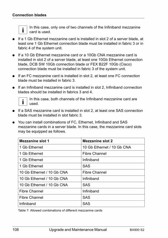
Connection blades
© c
ogni
tas.
Ges
ells
chft
für T
echn
ik-D
okum
enta
tion
mbH
201
1 P
fad:
C:\P
rogr
amm
e\FC
T\tim
_app
\tim
_loc
al\w
ork\
WA
LTE
R\O
BJ_
DO
KU
-136
59-0
01.fm
I In this case, only one of two channels of the Infiniband mezzanine card is used.
● If a 1 Gb Ethernet mezzanine card is installed in slot 2 of a server blade, at least one 1 Gb Ethernet connection blade must be installed in fabric 3 or in fabric 4 of the system unit.
● If a 10 Gb Ethernet mezzanine card or a 10Gb CNA mezzanine card is installed in slot 2 of a server blade, at least one 10Gb Ethernet connection blade, DCB SW 10Gb connection blade or FEX B22F 10Gb (Cisco) connection blade must be installed in fabric 3 of the system unit.
● If an FC mezzanine card is installed in slot 2, at least one FC connection blade must be installed in fabric 3.
● If an Infiniband mezzanine card is installed in slot 2, Infiniband connection blades should be installed in fabrics 3 and 4.
I In this case, both channels of the Infiniband mezzanine card are used.
● If a SAS mezzanine card is installed in slot 2, at least one SAS connection blade must be installed in slot fabric 3.
● You can install combinations of FC, Ethernet, Infiniband and SAS mezzanine cards in a server blade. In this case, the mezzanine card slots may be equipped as follows.
Mezzanine slot 1 Mezzanine slot 21 Gb Ethernet 10 Gb Ethernet / 10 Gb CNA1 Gb Ethernet Fibre Channel1 Gb Ethernet Infiniband1 Gb Ethernet SAS10 Gb Ethernet / 10 Gb CNA Fibre Channel10 Gb Ethernet / 10 Gb CNA Infiniband10 Gb Ethernet / 10 Gb CNA SASFibre Channel InfinibandFibre Channel SASInfiniband SAS
Table 7: Allowed combinations of different mezzanine cards
108 Upgrade and Maintenance Manual BX900 S2

Connection blades
8.1.2 Port assignment
For the on-board LAN controller, the Ethernet and Fibre Channel mezzanine cards of the server blades applies the following general rule: The A-channels (Ethernet: ports 1 and 3, FC: port 0) are connected to the connection blade slots on the left-hand side (CB1, CB3, CB5 and CB7). The B-channels (Ethernet: ports 2 and 4, FC: port 1) are connected to the slots on the right-hand side (CB2, CB4, CB6 and CB8).
For Infiniband mezzanine cards applies the following rule: Port 1 is connected to fabric 4 (CB7/8) and port 2 is connected to fabric 2 (CB3/4) and fabric 3 (CB5/6).
BX900 S2 Upgrade and Maintenance Manual 109

Connection blades
© c
ogni
tas.
Ges
ells
chft
für T
echn
ik-D
okum
enta
tion
mbH
201
1 P
fad:
C:\P
rogr
amm
e\FC
T\tim
_app
\tim
_loc
al\w
ork\
WA
LTE
R\O
BJ_
DO
KU
-136
59-0
01.fm
8.1.2.1 Port assignment of switch connection blades
With the mezzanine cards, the assignment of the ports to the connection blade slots can be defined via the management blade. The following table shows the different options.
For more information on configuring the connection blades, see the manual "PRIMERGY BX900 Blade Server Systems ServerView Management Blade S1 User Interface Description" and the documentation for the relevant connection blades.
mezzanine card Mezzanine card slot (M) Connection blade slot (CB)
Port (P) Port (P)
FC 8Gb/s
M1.P0 CB3
M1.P1 CB4
M2.P0 CB5
M2.P1 CB6
LAN 1GbE
M1.P1 / M1.P3 CB3.P1 / CB3.P2
M1.P2 / M1.P4 CB4.P1 / CB4.P2
M2.P1 / M2.P3 CB7.P1 / CB7.P2
M2.P2 / M2.P4 CB8.P1 / CB8.P2
LAN 1GbE M2.P1 / M2.P3 CB5.P1 / CB5.P2
Option 2 M2.P2 / M2.P4 CB6.P1 / CB6.P2
LAN 1GbE M2.P1 / M2.P3 CB5.P1 / CB7.P2
Option 3 M2.P2 / M2.P4 CB6.P1 / CB8.P2
LAN 10GbE / 10Gb CNA
M1.P1 CB3.P1
M1.P2 CB4.P1
M2.P1 CB5.P1
M2.P2 CB6.P1
Infiniband
M1.P1 ---
M1.P2 CB3/CB4
M2.P1 CB7/CB8
M2.P2 CB5/CB6
SAS 6GbM2.P1 CB5.P1
M2.P2 CB6.P1
Table 8: Port assignment of connection blades and mezzanine cards
110 Upgrade and Maintenance Manual BX900 S2
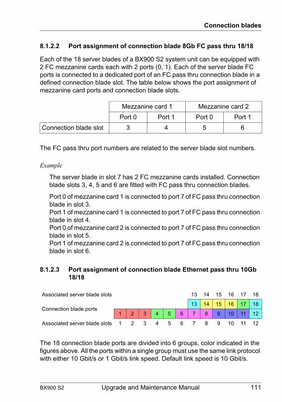
Connection blades
8.1.2.2 Port assignment of connection blade 8Gb FC pass thru 18/18
Each of the 18 server blades of a BX900 S2 system unit can be equipped with 2 FC mezzanine cards each with 2 ports (0, 1). Each of the server blade FC ports is connected to a dedicated port of an FC pass thru connection blade in a defined connection blade slot. The table below shows the port assignment of mezzanine card ports and connection blade slots.
The FC pass thru port numbers are related to the server blade slot numbers.
Example
The server blade in slot 7 has 2 FC mezzanine cards installed. Connection blade slots 3, 4, 5 and 6 are fitted with FC pass thru connection blades.
Port 0 of mezzanine card 1 is connected to port 7 of FC pass thru connection blade in slot 3.Port 1 of mezzanine card 1 is connected to port 7 of FC pass thru connection blade in slot 4.Port 0 of mezzanine card 2 is connected to port 7 of FC pass thru connection blade in slot 5.Port 1 of mezzanine card 2 is connected to port 7 of FC pass thru connection blade in slot 6.
8.1.2.3 Port assignment of connection blade Ethernet pass thru 10Gb 18/18
The 18 connection blade ports are divided into 6 groups, color indicated in the figures above. All the ports within a single group must use the same link protocol with either 10 Gbit/s or 1 Gbit/s link speed. Default link speed is 10 Gbit/s.
Mezzanine card 1 Mezzanine card 2Port 0 Port 1 Port 0 Port 1
Connection blade slot 3 4 5 6
Associated server blade slots 13 14 15 16 17 18
Connection blade ports13 14 15 16 17 18
1 2 3 4 5 6 7 8 9 10 11 12
Associated server blade slots 1 2 3 4 5 6 7 8 9 10 11 12
BX900 S2 Upgrade and Maintenance Manual 111

Connection blades
© c
ogni
tas.
Ges
ells
chft
für T
echn
ik-D
okum
enta
tion
mbH
201
1 P
fad:
C:\P
rogr
amm
e\FC
T\tim
_app
\tim
_loc
al\w
ork\
WA
LTE
R\O
BJ_
DO
KU
-136
59-0
01.fm
The configuration of the connection blade is controlled by the management blade. Each port group can be configured to a certain link protocol. The management blade web interface allows the user to modify the port group link speed configuration.
8.2 Single-width connection blades
8.2.1 Installing single-width connection blades
8.2.1.1 Required tools
● Preliminary and concluding steps: tool-less
● Installing connection blades: tool-less
8.2.1.2 Preliminary steps
Before installing a single-width connection blade, perform the following steps:
Ê If applicable, open the rack door as described in section "Opening the rack door" on page 48.
Ê Locate the desired system unit as described in section "Determining the error class" on page 45.
Ê Locate the mounting bay for the new connection blade using the information in section "Connection blade fitting rules" on page 106.
Upgrade and Repair Units (URU)
average hardware task duration: 5 minutes
average software task duration: 10 minutes
112 Upgrade and Maintenance Manual BX900 S2

Connection blades
8.2.1.3 Removing connection blade dummy module
Figure 21: Removing a dummy connection blade module
Ê Press the handles of the dummy module inward and pull it out of the slot.
V CAUTION!
Keep the dummy modules for future use.
Always replace connection blade dummy modules into unused connection blade slots to comply with applicable EMC regulations and satisfy cooling requirements.
8.2.1.4 Installing a single-width connection blade
Ê Unpack the connection blade.
BX900 S2 Upgrade and Maintenance Manual 113
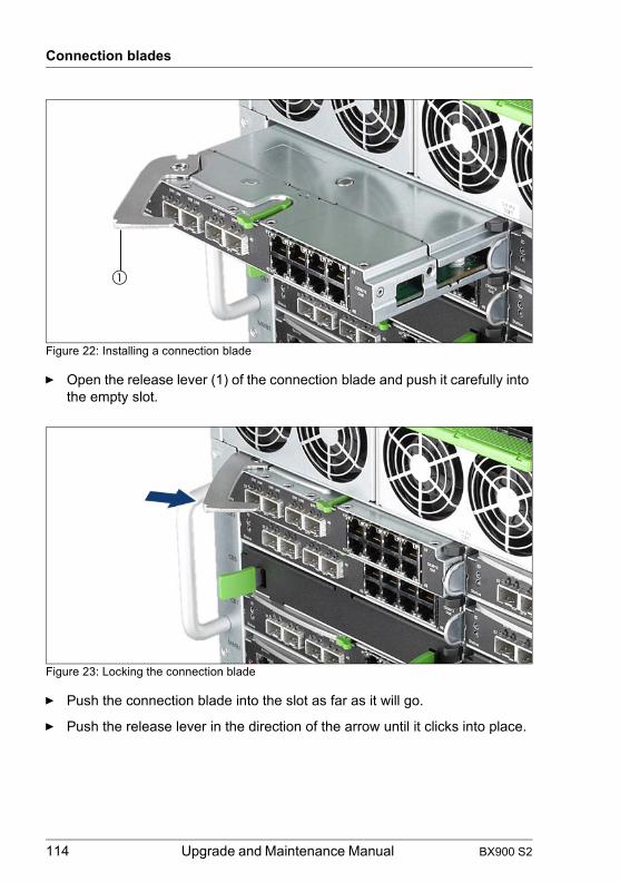
Connection blades
© c
ogni
tas.
Ges
ells
chft
für T
echn
ik-D
okum
enta
tion
mbH
201
1 P
fad:
C:\P
rogr
amm
e\FC
T\tim
_app
\tim
_loc
al\w
ork\
WA
LTE
R\O
BJ_
DO
KU
-136
59-0
01.fm
Figure 22: Installing a connection blade
Ê Open the release lever (1) of the connection blade and push it carefully into the empty slot.
Figure 23: Locking the connection blade
Ê Push the connection blade into the slot as far as it will go.
Ê Push the release lever in the direction of the arrow until it clicks into place.
114 Upgrade and Maintenance Manual BX900 S2

Connection blades
8.2.1.5 Concluding steps
Perform the following procedures to complete the task:
Ê If applicable, install the SFP transceiver modules as described in section "Installing SFP+ transceiver modules" on page 127
Ê Connect the external cables to the connection blade.
Ê If applicable, integrate the connection blade in a connection blade stack as described in section "Connection blade stacking" on page 137.
I This step only applies to the connection blade GbE Switch/IBP 36/8+2 (SB11).
Ê If applicable, close the rack door as described in section "Closing the rack door" on page 60.
Ê Configure the connection blade settings as described in section "Configuring connection blade settings" on page 75.
Ê Create a backup copy of the connection blade settings as described in section "Saving connection blade settings" on page 76.
8.2.2 Removing single-width connection blades
8.2.2.1 Required tools
● Preliminary and concluding steps: tool-less
● Removing connection blades: tool-less
8.2.2.2 Preliminary steps
Before removing a single-width connection blade, perform the following steps:
Upgrade and Repair Units (URU)
average hardware task duration: 5 minutes
average software task duration: 10 minutes
BX900 S2 Upgrade and Maintenance Manual 115

Connection blades
© c
ogni
tas.
Ges
ells
chft
für T
echn
ik-D
okum
enta
tion
mbH
201
1 P
fad:
C:\P
rogr
amm
e\FC
T\tim
_app
\tim
_loc
al\w
ork\
WA
LTE
R\O
BJ_
DO
KU
-136
59-0
01.fm
Ê Save the connection blade settings as described in section "Saving connection blade settings" on page 76.
Ê If applicable, open the rack door as described in section "Opening the rack door" on page 48.
Ê Locate the desired system unit as described in section "Determining the error class" on page 45.
Ê Locate the desired connection blade as described in section "Locating the defective component" on page 48.
Ê If applicable, disconnect cables from the connection blade.
Ê If applicable, remove SFP transceiver modules from the connection blade as described in section "Removing an SFP+ transceiver module" on page 133.
8.2.2.3 Removing a single-width connection blade
Figure 24: Removing a connection blade
Ê Unlock the locking lever (1) and open the release lever (2).
Ê Carefully remove the connection blade from its slot.
116 Upgrade and Maintenance Manual BX900 S2

Connection blades
8.2.2.4 Installing a connection blade dummy module
Figure 25: Installing a dummy connection blade module
Ê Push the connection blade dummy module into the slot until the handles click into place.
8.2.2.5 Concluding steps
Perform the following procedures to complete the task:
Ê If applicable, close the rack door as described in section "Closing the rack door" on page 60.
8.2.3 Replacing single-width connection blades
8.2.3.1 Required tools
● Preliminary and concluding steps: tool-less
● Installing connection blades: tool-less
Upgrade and Repair Units (URU)
average hardware task duration: 5 minutes
average software task duration: 10 minutes
BX900 S2 Upgrade and Maintenance Manual 117
Connection blades
© c
ogni
tas.
Ges
ells
chft
für T
echn
ik-D
okum
enta
tion
mbH
201
1 P
fad:
C:\P
rogr
amm
e\FC
T\tim
_app
\tim
_loc
al\w
ork\
WA
LTE
R\O
BJ_
DO
KU
-136
59-0
01.fm
8.2.3.2 Preliminary steps
Before replacing a single-width connection blade, perform the following steps:
Ê If possible, save the connection blade settings as described in section "Saving connection blade settings" on page 76.
Ê If applicable, open the rack door as described in section "Opening the rack door" on page 48.
Ê Locate the desired system unit as described in section "Determining the error class" on page 45.
Ê Locate the defective connection blade as described in section "Locating the defective component" on page 48.
Ê If applicable, disconnect cables from the connection blade.
Ê If applicable, remove SFP transceiver modules from the connection blade as described in section "Removing an SFP+ transceiver module" on page 133.
8.2.3.3 Removing a connection blade
Ê Remove the defective connection blade as described in section "Removing a single-width connection blade" on page 116
8.2.3.4 Installing a single-width connection blade
Ê Install the new connection blade as described in section "Installing a single-width connection blade" on page 113
8.2.3.5 Concluding steps
Perform the following procedures to complete the task:
Ê If applicable, reinstall the SFP transceiver modules as described in section "Installing SFP+ transceiver modules" on page 127
Ê Reconnect all external cables to the replaced connection blade.
Ê If applicable, integrate the connection blade in a connection blade stack as described in section "Connection blade stacking" on page 137.
I This step only applies to the connection blade GbE Switch/IBP 36/8+2 (SB11).
118 Upgrade and Maintenance Manual BX900 S2
Connection blades
Ê If applicable, close the rack door as described in section "Closing the rack door" on page 60.
Ê Make sure, that the new connection blade has the same firmware version as the old one as described in section "Updating the connection blade firmware" on page 74.
Ê If applicable, migrate the Fibre Channel connection blade license to the new connection blade. Please follow the instructions provided separately.
Ê Restore the connection blade settings from the backup copy as described in section "Restoring connection blade settings" on page 78.
8.3 Double-width connection blades
8.3.1 Installing double-width connection blades
8.3.1.1 Required tools
● Preliminary and concluding steps: tool-less
● Installing connection blades: tool-less
8.3.1.2 Preliminary steps
Before installing a double-width connection blade, perform the following steps:
Ê If applicable, open the rack door as described in section "Opening the rack door" on page 48.
Ê Locate the desired system unit as described in section "Determining the error class" on page 45.
Upgrade and Repair Units (URU)
average hardware task duration: 5 minutes
average software task duration: 10 minutes
BX900 S2 Upgrade and Maintenance Manual 119

Connection blades
© c
ogni
tas.
Ges
ells
chft
für T
echn
ik-D
okum
enta
tion
mbH
201
1 P
fad:
C:\P
rogr
amm
e\FC
T\tim
_app
\tim
_loc
al\w
ork\
WA
LTE
R\O
BJ_
DO
KU
-136
59-0
01.fm
Ê Locate the mounting bay for the new connection blade using the information in section "Connection blade fitting rules" on page 106.
8.3.1.3 Removing connection blade dummy modules
Ê Remove the connection blade dummy modules from the side by side slots of a fabric as described in section "Removing connection blade dummy module" on page 113.
V CAUTION!
Keep the dummy modules for future use.
Always replace connection blade dummy modules into unused connection blade slots to comply with applicable EMC regulations and satisfy cooling requirements.
8.3.1.4 Installing a double-width connection blade (Infiniband)
Ê Unpack the Infiniband connection blade.
Figure 26: Removing the separating clip
120 Upgrade and Maintenance Manual BX900 S2
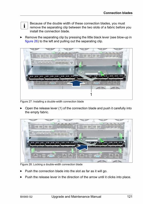
Connection blades
I Because of the double width of these connection blades, you must remove the separating clip between the two slots of a fabric before you install the connection blade.
Ê Remove the separating clip by pressing the little black lever (see blow-up in figure 26) to the left and pulling out the separating clip.
Figure 27: Installing a double-width connection blade
Ê Open the release lever (1) of the connection blade and push it carefully into the empty fabric.
Figure 28: Locking a double-width connection blade
Ê Push the connection blade into the slot as far as it will go.
Ê Push the release lever in the direction of the arrow until it clicks into place.
1
BX900 S2 Upgrade and Maintenance Manual 121

Connection blades
© c
ogni
tas.
Ges
ells
chft
für T
echn
ik-D
okum
enta
tion
mbH
201
1 P
fad:
C:\P
rogr
amm
e\FC
T\tim
_app
\tim
_loc
al\w
ork\
WA
LTE
R\O
BJ_
DO
KU
-136
59-0
01.fm
8.3.1.5 Concluding steps
Perform the following procedures to complete the task:
Ê Install the QSFP transceiver modules as described in section "Installing SFP+ transceiver modules" on page 127
Ê Connect the external cables to the connection blade.
Ê If applicable, close the rack door as described in section "Closing the rack door" on page 60.
Ê Configure the connection blade settings as described in section "Configuring connection blade settings" on page 75.
Ê Create a backup copy of the connection blade settings as described in section "Saving connection blade settings" on page 76.
122 Upgrade and Maintenance Manual BX900 S2
Connection blades
8.3.2 Removing double-width connection blades
8.3.2.1 Required tools
● Preliminary and concluding steps: tool-less
● Removing connection blades: tool-less
8.3.2.2 Preliminary steps
Before removing a double-width connection blade, perform the following steps:
Ê Save the connection blade settings as described in section "Saving connection blade settings" on page 76.
Ê If applicable, open the rack door as described in section "Opening the rack door" on page 48.
Ê Locate the desired system unit as described in section "Determining the error class" on page 45.
Ê Locate the desired connection blade as described in section "Locating the defective component" on page 48.
Ê If applicable, disconnect cables from the connection blade.
Ê If applicable, remove QSFP transceiver modules from the connection blade as described in section "Removing an SFP+ transceiver module" on page 133.
Upgrade and Repair Units (URU)
average hardware task duration: 5 minutes
average software task duration: 10 minutes
BX900 S2 Upgrade and Maintenance Manual 123

Connection blades
© c
ogni
tas.
Ges
ells
chft
für T
echn
ik-D
okum
enta
tion
mbH
201
1 P
fad:
C:\P
rogr
amm
e\FC
T\tim
_app
\tim
_loc
al\w
ork\
WA
LTE
R\O
BJ_
DO
KU
-136
59-0
01.fm
8.3.2.3 Removing a double-width connection blade
Figure 29: Removing a double-width connection blade
Ê Unlock the locking lever (1) and open the release lever (2).
Ê Carefully remove the connection blade from its slot.
8.3.2.4 Installing connection blade dummy modules
Figure 30: Installing the separating clip between the connection blade slots
Ê Install the separating clip between the slots.
Ê Install the connection blade dummy modules into the unused slots as described in section "Installing a connection blade dummy module" on page 117.
124 Upgrade and Maintenance Manual BX900 S2

Connection blades
8.3.2.5 Concluding steps
Perform the following procedures to complete the task:
Ê If applicable, close the rack door as described in section "Closing the rack door" on page 60.
8.3.3 Replacing double-width connection blades
8.3.3.1 Required tools
● Preliminary and concluding steps: tool-less
● Installing connection blades: tool-less
8.3.3.2 Preliminary steps
Before replacing a double-width connection blade, perform the following steps:
Ê If possible, save the connection blade settings as described in section "Saving connection blade settings" on page 76.
Ê If applicable, open the rack door as described in section "Opening the rack door" on page 48.
Ê Locate the desired system unit as described in section "Determining the error class" on page 45.
Ê Locate the defective connection blade as described in section "Locating the defective component" on page 48.
Ê If applicable, disconnect cables from the connection blade.
Ê If applicable, remove QSFP transceiver modules from the connection blade as described in section "Removing an SFP+ transceiver module" on page 133.
Upgrade and Repair Units (URU)
average hardware task duration: 5 minutes
average software task duration: 10 minutes
BX900 S2 Upgrade and Maintenance Manual 125
Connection blades
© c
ogni
tas.
Ges
ells
chft
für T
echn
ik-D
okum
enta
tion
mbH
201
1 P
fad:
C:\P
rogr
amm
e\FC
T\tim
_app
\tim
_loc
al\w
ork\
WA
LTE
R\O
BJ_
DO
KU
-136
59-0
01.fm
8.3.3.3 Removing the connection blade
Ê Remove the defective connection blade as described in section "Removing a double-width connection blade" on page 124.
8.3.3.4 Installing a double-width connection blade
Ê Install the new connection blade as described in section "Installing a double-width connection blade (Infiniband)" on page 120.
8.3.3.5 Concluding steps
Perform the following procedures to complete the task:
Ê Reinstall the QSFP transceiver modules in the connection blade as described in section "Installing SFP+ transceiver modules" on page 127.
Ê Reconnect all external cables to the connection blade.
Ê If applicable, close the rack door as described in section "Closing the rack door" on page 60.
Ê Make sure, that the new connection blade has the same firmware version as the old one as described in section "Updating the connection blade firmware" on page 74.
Ê Restore the connection blade settings from the backup copy as described in section "Restoring connection blade settings" on page 78.
126 Upgrade and Maintenance Manual BX900 S2

Connection blades
8.4 Additional tasks
This section provides additional connection blade related information on how to install SFP+ transceiver modules.
I For further instructions regarding connection blade settings, please refer to the accompanying documentation.
8.4.1 Handling SFP+ transceiver modules
8.4.1.1 Installing SFP+ transceiver modules
Required tools
● Preliminary and concluding steps: tool-less
● Installing SFP+ transceiver modules: tool-less
Customer Replaceable Units (CRU)
Average task duration: 5 minutes
BX900 S2 Upgrade and Maintenance Manual 127
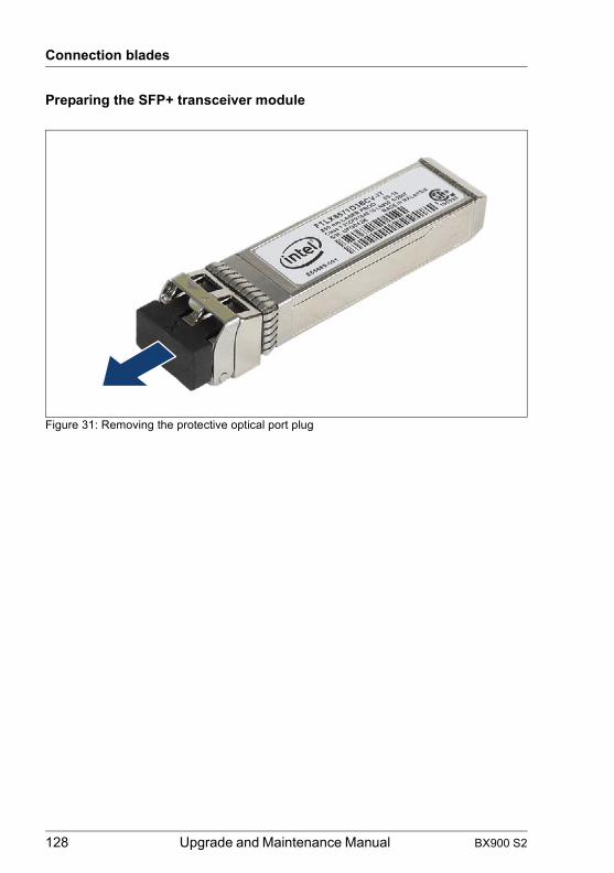
Connection blades
© c
ogni
tas.
Ges
ells
chft
für T
echn
ik-D
okum
enta
tion
mbH
201
1 P
fad:
C:\P
rogr
amm
e\FC
T\tim
_app
\tim
_loc
al\w
ork\
WA
LTE
R\O
BJ_
DO
KU
-136
59-0
01.fm
Preparing the SFP+ transceiver module
Figure 31: Removing the protective optical port plug
128 Upgrade and Maintenance Manual BX900 S2

Connection blades
Ê Remove the SFP+ transceiver module from its protective packaging.
Ê Remove the optical port plug from the new / additional SFP+ transceiver module.
V CAUTION!
– Always keep the protective port plugs attached to the transceiver optical bores and fiber-optic cable connectors until you are ready to make a connection.
– Save the protective port plug for future use.
Figure 32: Unlatching the locking bail
Ê Carefully unlatch and fold down the locking bail on the SFP+ transceiver module.
BX900 S2 Upgrade and Maintenance Manual 129
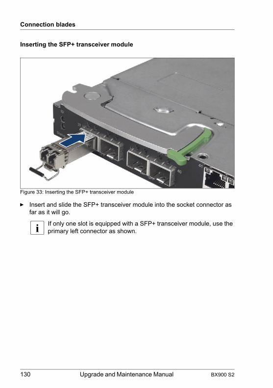
Connection blades
© c
ogni
tas.
Ges
ells
chft
für T
echn
ik-D
okum
enta
tion
mbH
201
1 P
fad:
C:\P
rogr
amm
e\FC
T\tim
_app
\tim
_loc
al\w
ork\
WA
LTE
R\O
BJ_
DO
KU
-136
59-0
01.fm
Inserting the SFP+ transceiver module
Figure 33: Inserting the SFP+ transceiver module
Ê Insert and slide the SFP+ transceiver module into the socket connector as far as it will go.
I If only one slot is equipped with a SFP+ transceiver module, use the primary left connector as shown.
130 Upgrade and Maintenance Manual BX900 S2

Connection blades
Figure 34: Latching the locking bail
Ê Carefully fold up and latch the locking bail.
Figure 35: Attaching the protective optical port plug
BX900 S2 Upgrade and Maintenance Manual 131

Connection blades
© c
ogni
tas.
Ges
ells
chft
für T
echn
ik-D
okum
enta
tion
mbH
201
1 P
fad:
C:\P
rogr
amm
e\FC
T\tim
_app
\tim
_loc
al\w
ork\
WA
LTE
R\O
BJ_
DO
KU
-136
59-0
01.fm
Ê If the SFP+ transceiver module is not immediately connected to an LC connector, attach the protective optical port plug to the transceiver optical bores.
132 Upgrade and Maintenance Manual BX900 S2
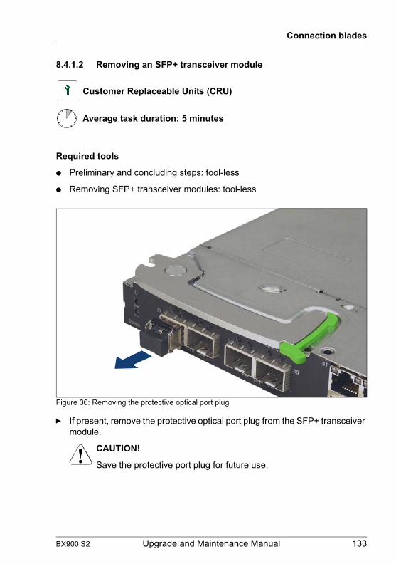
Connection blades
8.4.1.2 Removing an SFP+ transceiver module
Required tools
● Preliminary and concluding steps: tool-less
● Removing SFP+ transceiver modules: tool-less
Figure 36: Removing the protective optical port plug
Ê If present, remove the protective optical port plug from the SFP+ transceiver module.
V CAUTION!
Save the protective port plug for future use.
Customer Replaceable Units (CRU)
Average task duration: 5 minutes
BX900 S2 Upgrade and Maintenance Manual 133
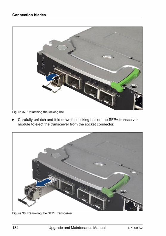
Connection blades
© c
ogni
tas.
Ges
ells
chft
für T
echn
ik-D
okum
enta
tion
mbH
201
1 P
fad:
C:\P
rogr
amm
e\FC
T\tim
_app
\tim
_loc
al\w
ork\
WA
LTE
R\O
BJ_
DO
KU
-136
59-0
01.fm
Figure 37: Unlatching the locking bail
Ê Carefully unlatch and fold down the locking bail on the SFP+ transceiver module to eject the transceiver from the socket connector.
Figure 38: Removing the SFP+ transceiver
134 Upgrade and Maintenance Manual BX900 S2

Connection blades
Ê Pull the SFP+ transceiver module out of its socket connector.
Ê Reattach the protective optical port plug to the transceiver optical bores.
I Place the removed SFP+ transceiver module in an antistatic bag or other protective environment.
BX900 S2 Upgrade and Maintenance Manual 135

Connection blades
© c
ogni
tas.
Ges
ells
chft
für T
echn
ik-D
okum
enta
tion
mbH
201
1 P
fad:
C:\P
rogr
amm
e\FC
T\tim
_app
\tim
_loc
al\w
ork\
WA
LTE
R\O
BJ_
DO
KU
-136
59-0
01.fm
8.4.1.3 Replacing SFP+ transceiver modules
Required tools
● Preliminary and concluding steps: tool-less
● Removing SFP+ transceiver modules: tool-less
Removing SFP+ transceiver modules
Ê Remove the defective SFP+ transceiver module(s) as described in section "Removing an SFP+ transceiver module" on page 133.
Installing SFP+ transceiver modules
Ê Unpack the new SFP+ transceiver module.
Ê Verify that the new SFP+ transceiver module is the same type of transceiver you are replacing.
Ê Install the new SFP+ transceiver module(s) as described in section "Installing SFP+ transceiver modules" on page 127.
Customer Replaceable Units (CRU)
Average task duration: 5 minutes
136 Upgrade and Maintenance Manual BX900 S2

Connection blades
8.4.2 Connection blade stacking
Up to 8 Connection Blades GbE Switch/IBP 36/8+2 (SB11) can be operated together to form a so-called stack. One of the connection blades takes on the role of the master. This connection blade is used to administer all modules of the stack. All modules of a stack act as one connection blade. In this way, connection blade stacking offers a large number of ports with minimum administrative effort.
The connections within a stack are established through the stacking ports of the connection blades. The internal stacking ports to the midplane of the BX900 S2 system unit are each used to connect two connection blades that are installed in the same fabric, i.e. in two adjacent slots. Connection blades in different fabrics are connected through the external ports using CX4 cables.
Figure 39: CX4 cable
The stacking connections within a stack must form a circuit. Connection blade stacks can be formed within a BX900 S2 system unit, across several system units of a rack or across several system units in different racks.
The possible cabling scenarios are shown in the following diagrams, with the connections identified as follows:
Internal connection within a fabric via the midplaneCX4 cable, 0.5 mCX4 cable, 3 m
BX900 S2 Upgrade and Maintenance Manual 137
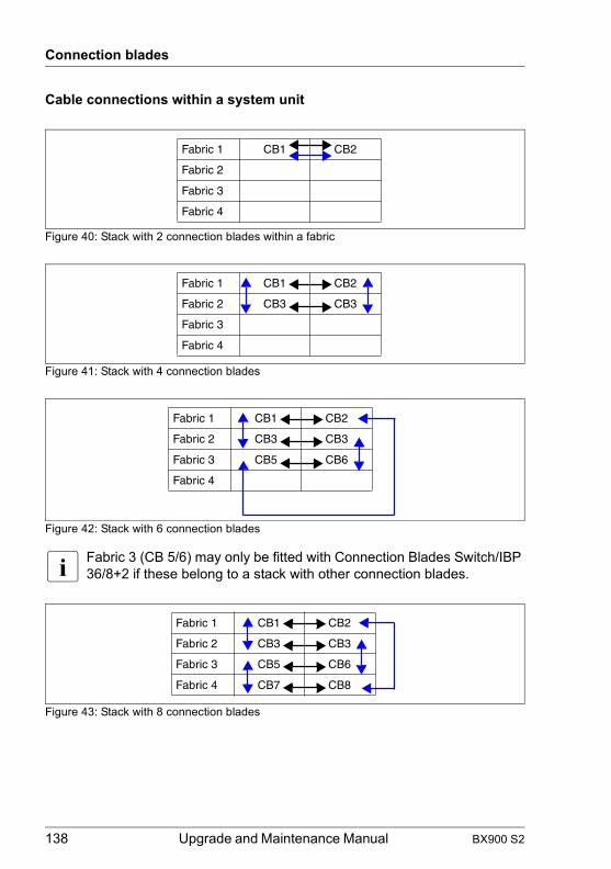
Connection blades
© c
ogni
tas.
Ges
ells
chft
für T
echn
ik-D
okum
enta
tion
mbH
201
1 P
fad:
C:\P
rogr
amm
e\FC
T\tim
_app
\tim
_loc
al\w
ork\
WA
LTE
R\O
BJ_
DO
KU
-136
59-0
01.fm
Cable connections within a system unit
Figure 40: Stack with 2 connection blades within a fabric
Figure 41: Stack with 4 connection blades
Figure 42: Stack with 6 connection blades
I Fabric 3 (CB 5/6) may only be fitted with Connection Blades Switch/IBP 36/8+2 if these belong to a stack with other connection blades.
Figure 43: Stack with 8 connection blades
Fabric 1 CB1 CB2
Fabric 2
Fabric 3
Fabric 4
Fabric 1 CB1 CB2
Fabric 2 CB3 CB3
Fabric 3
Fabric 4
Fabric 1 CB1 CB2
Fabric 2 CB3 CB3
Fabric 3 CB5 CB6
Fabric 4
Fabric 1 CB1 CB2
Fabric 2 CB3 CB3
Fabric 3 CB5 CB6
Fabric 4 CB7 CB8
138 Upgrade and Maintenance Manual BX900 S2

Connection blades
Cable connections across several system units
Figure 44: Stack with 8 connection blades in 4 system units in a rack (variant 1)
Fabric 1 CB1 CB2
Fabric 2 CB3 CB3
Fabric 3 CB5 CB6
Fabric 4 CB7 CB8
Fabric 1 CB1 CB2
Fabric 2 CB3 CB3
Fabric 3 CB5 CB6
Fabric 4 CB7 CB8
Fabric 1 CB1 CB2
Fabric 2 CB3 CB3
Fabric 3 CB5 CB6
Fabric 4 CB7 CB8
Fabric 1 CB1 CB2
Fabric 2 CB3 CB3
Fabric 3 CB5 CB6
Fabric 4 CB7 CB8
BX900 S2 Upgrade and Maintenance Manual 139
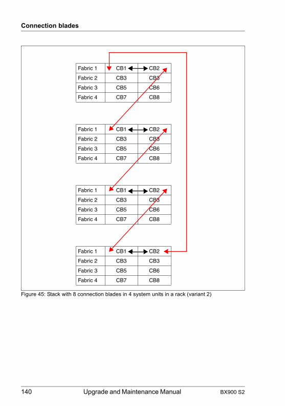
Connection blades
© c
ogni
tas.
Ges
ells
chft
für T
echn
ik-D
okum
enta
tion
mbH
201
1 P
fad:
C:\P
rogr
amm
e\FC
T\tim
_app
\tim
_loc
al\w
ork\
WA
LTE
R\O
BJ_
DO
KU
-136
59-0
01.fm
Figure 45: Stack with 8 connection blades in 4 system units in a rack (variant 2)
Fabric 1 CB1 CB2
Fabric 2 CB3 CB3
Fabric 3 CB5 CB6
Fabric 4 CB7 CB8
Fabric 1 CB1 CB2
Fabric 2 CB3 CB3
Fabric 3 CB5 CB6
Fabric 4 CB7 CB8
Fabric 1 CB1 CB2
Fabric 2 CB3 CB3
Fabric 3 CB5 CB6
Fabric 4 CB7 CB8
Fabric 1 CB1 CB2
Fabric 2 CB3 CB3
Fabric 3 CB5 CB6
Fabric 4 CB7 CB8
140 Upgrade and Maintenance Manual BX900 S2

Connection blades
Supported combinations for connection blade stacks
The following table shows the possible combinations of connection blade stacks. Columns a - f contain permissible numbers and distributions of the connection blades for the different combinations of BX900 S2 system units and racks.
Rack (R)System unit (Z)
Fitting variants of connection blades
a b c d e f
1 rack, 1 system unit R1 Z1 2 4 6 8
1 rack, 2 system units R1 Z1 2 4 6 2 4 2
Z2 2 2 2 4 4 6
1 rack, 3 system units R1 Z1 2 4 2 2
Z2 2 2 4 2
Z3 2 2 2 4
1 rack, 4 system units R1 Z1 2
Z2 2
Z3 2
Z4 2
2 racks, 2 system units R1 Z1 2 4 6 2 4 2
R2 Z2 2 2 2 4 4 6
2 racks, 3 system units R1 Z1 2 4 2 2
R1 Z2 2 2 4 2
R2 Z3 2 2 2 4
2 racks, 4 system units R1 Z1 2
R1 Z2 2
R1 Z3 2
R2 Z4 2
3 racks, 3 system units R1 Z1 2 4 2 2
R2 Z2 2 2 4 2
R3 Z3 2 2 2 4
3 racks, 4 system units R1 Z1 2
R1 Z2 2
R2 Z3 2
R3 Z4 2
BX900 S2 Upgrade and Maintenance Manual 141

Connection blades
© c
ogni
tas.
Ges
ells
chft
für T
echn
ik-D
okum
enta
tion
mbH
201
1 P
fad:
C:\P
rogr
amm
e\FC
T\tim
_app
\tim
_loc
al\w
ork\
WA
LTE
R\O
BJ_
DO
KU
-136
59-0
01.fm
Further information
For more detailed information and additional possible configurations, see the manuals "PRIMERGY BX900 Blade Server Systems – Ethernet Connection Blade Module IBP Version – User’s Guide", "PRIMERGY BX900 Blade Server Systems – Ethernet Connection Blade Module Switch Version – User’s Guide".
Rack (R)System unit (Z)
Fitting variants of connection blades
a b c d e f
4 racks, 4 system units R1 Z1 2
R2 Z2 2
R3 Z3 2
R4 Z4 2
142 Upgrade and Maintenance Manual BX900 S2
9 Management Blades
9.1 Basic information
The PRIMERGY BX900 S2 system unit has slots for two management blades for complete remote administration of the system, MMB 1 and MMB 2 in figure "PRIMERGY BX900 S2 system unit rear" on page 176. The basic configuration of the BX900 S2 system unit contains one management blade.
If two management blades are installed in the system unit, one will take over the role of the master, who is in charge of the server management, while the other one will take over the slave role and remain in a standby status as a redundant component. As soon as the master fails to work properly, for instance, when unplugged by the system administrator, the standby component will take over control of the server management.
For a detailed description, see the manual "PRIMERGY BX900 Blade Server Systems ServerView Management Blade S1 User Interface Description".
V CAUTION!
When installing or replacing a management blade, make sure that the new management blade has the required firmware version.
– If two management blades are installed in the system unit, the firmware version of the slave management blade must match the firmware version of the master.
– If one management blade is installed in the system unit, the firmware version of the new management blade must be at least equal to the firmware version of the old one.
If the firmware version of the old management blade is unknown, you must update the firmware to the latest version.
BX900 S2 Upgrade and Maintenance Manual 143

Management Blades
© c
ogni
tas.
Ges
ells
chft
für T
echn
ik-D
okum
enta
tion
mbH
201
1 P
fad:
C:\P
rogr
amm
e\FC
T\tim
_app
\tim
_loc
al\w
ork\
WA
LTE
R\O
BJ_
DO
KU
-136
64-0
01.fm
9.2 Installing a second management blade
9.2.1 Required tools
● Preliminary and concluding steps: tool-less
● Installing connection blades: tool-less
9.2.2 Preliminary steps
Before installing a management blade, perform the following steps:
Ê If applicable, open the rack door as described in section "Opening the rack door" on page 48.
Ê Locate the desired system unit as described in section "Determining the error class" on page 45.
Ê Connect a field service terminal to the installed management blade as described in section "Accessing the management blade web interface" on page 44.
Ê Take a note of the firmware version of the installed management blade as described in section "Looking up the management blade firmware version" on page 66.
9.2.3 Removing the management blade dummy module
Ê Remove the management blade dummy module from the unused management blade bay.
Field Replaceable Units (FRU)
average hardware task duration: 5 minutes
average software task duration: 10 minutes
144 Upgrade and Maintenance Manual BX900 S2

Management Blades
A management blade dummy module is removed in the same way as a connection blade dummy module as described in section "Removing connection blade dummy module" on page 113.
V CAUTION!
Keep the dummy module for future use.
Always replace the management blade dummy module into an unused management blade slot to comply with applicable EMC regulations and satisfy cooling requirements.
9.2.4 Installing the management blade
Ê Unpack the management blade.
Ê Install the management blade in the system unit.
A management blade is installed in the same way as a single-width connection blade as described in section "Installing a single-width connection blade" on page 113.
9.2.5 Concluding steps
Perform the following procedures to complete the task:
Ê Wait until the boot process of new management blade has finished.
Ê Check the firmware version of the new management blade as described in section "Looking up the management blade firmware version" on page 66.
Ê If applicable, update the firmware of the new management blade as described in section "Updating / recovering the management blade firmware" on page 66.
Ê Check the management blade master/slave behavior as described in section "Checking management master/slave behavior" on page 73.
Ê Verify the time settings of the new management blade as described in section "Verifying the management blade time settings" on page 70.
Ê Disconnect the field service terminal from the management blade.
Ê If applicable, close the rack door as described in section "Closing the rack door" on page 60.
BX900 S2 Upgrade and Maintenance Manual 145

Management Blades
© c
ogni
tas.
Ges
ells
chft
für T
echn
ik-D
okum
enta
tion
mbH
201
1 P
fad:
C:\P
rogr
amm
e\FC
T\tim
_app
\tim
_loc
al\w
ork\
WA
LTE
R\O
BJ_
DO
KU
-136
64-0
01.fm
9.3 Replacing a management blade
9.3.1 Required tools
● Preliminary and concluding steps: tool-less
● Installing connection blades: tool-less
9.3.2 Preliminary steps
Before replacing a management blade, perform the following steps:
Ê If applicable, open the rack door as described in section "Opening the rack door" on page 48.
Ê Locate the desired system unit as described in section "Determining the error class" on page 45.
Ê Locate the defective management blade as described in section "Locating the defective component" on page 48.
The following step applies if only one management blade is installed in the system unit.
Ê Ask the system administrator for the firmware version of the defective management blade.
The following steps applies if two management blades are installed in the system unit.
Ê Connect a field service terminal to the master management blade as described in section "Accessing the management blade web interface" on page 44.
Field Replaceable Units (FRU)
average hardware task duration: 5 minutes
average software task duration: 10 minutes
146 Upgrade and Maintenance Manual BX900 S2
Management Blades
Ê Take a note of the firmware version of the master management blade as described in section "Looking up the management blade firmware version" on page 66.
9.3.3 Removing the defective management blade
Ê Remove the defective management blade.
A management blade is removed in the same way as a single-width connection blade as described in section "Removing a single-width connection blade" on page 116.
9.3.4 Installing the management blade
Ê Unpack the management blade.
Ê Install the management blade in the system unit.
A management blade is installed in the same way as a single-width connection blade as described in section "Installing a single-width connection blade" on page 113.
9.3.5 Concluding steps
Perform the following procedures to complete the task:
Ê Wait until the boot process of new management blade has finished.
Ê If one management blade is installed, connect a field service terminal to the management blade as described in section "Accessing the management blade web interface" on page 44.
Ê Check the firmware version of the new management blade as described in section "Looking up the management blade firmware version" on page 66.
Ê If applicable, update the firmware of the new management blade as described in section "Updating / recovering the management blade firmware" on page 66.
Ê If two management blades are installed, check the management blade master/slave behavior as described in section "Checking management master/slave behavior" on page 73.
BX900 S2 Upgrade and Maintenance Manual 147

Management Blades
© c
ogni
tas.
Ges
ells
chft
für T
echn
ik-D
okum
enta
tion
mbH
201
1 P
fad:
C:\P
rogr
amm
e\FC
T\tim
_app
\tim
_loc
al\w
ork\
WA
LTE
R\O
BJ_
DO
KU
-136
64-0
01.fm
Ê Verify the time settings of the new management blade as described in section "Verifying the management blade time settings" on page 70.
Ê Disconnect the field service terminal from the management blade.
Ê If applicable, close the rack door as described in section "Closing the rack door" on page 60.
9.4 Replacing the management blade battery
9.4.1 Required tools
● Preliminary and concluding steps: tool-less
● Installing connection blades: tool-less
9.4.2 Preliminary steps
Before replacing a management blade, perform the following steps:
Ê If applicable, open the rack door as described in section "Opening the rack door" on page 48.
Ê Locate the desired system unit as described in section "Determining the error class" on page 45.
Ê Locate the defective management blade as described in section "Locating the defective component" on page 48.
9.4.3 Replacing the management blade battery
Ê Remove the defective management blade.
Field Replaceable Units (FRU)
Average task duration: 5 minutes
148 Upgrade and Maintenance Manual BX900 S2

Management Blades
A management blade is removed in the same way as a single-width connection blade as described in section "Removing a single-width connection blade" on page 116.
Opening the management blade
Figure 46: Opening the management blade
Ê Press on the touch point (1) to release the lock, and slide the housing cover as far as it will go in the direction of the arrow (2).
Ê Take off the housing cover.
The management blade components are now freely accessible. The following figure shows the position of the battery.
Figure 47: Position of the management blade battery (1)
BX900 S2 Upgrade and Maintenance Manual 149

Management Blades
© c
ogni
tas.
Ges
ells
chft
für T
echn
ik-D
okum
enta
tion
mbH
201
1 P
fad:
C:\P
rogr
amm
e\FC
T\tim
_app
\tim
_loc
al\w
ork\
WA
LTE
R\O
BJ_
DO
KU
-136
64-0
01.fm
Figure 48: Installing/removing the management blade battery
Ê Press the locking springs in the direction of the arrow (1) so that the lithium battery is ejected from its holder, and remove the battery (2).
Ê Place the new battery of the same type in the holder (3) and press it in the direction of the arrow (4) until it clicks into place.
Ê Close the management blade cover in the opposite order to that described above, see "Opening the management blade" on page 149.
Ê Reinstall the management blade in the system unit.
A management blade is installed in the same way as a single-width connection blade as described in section "Installing a single-width connection blade" on page 113.
9.4.4 Concluding steps
Perform the following procedures to complete the task:
Ê Verify the time settings of the management blade as described in section "Verifying the management blade time settings" on page 70.
Ê If applicable, close the rack door as described in section "Closing the rack door" on page 60.
1
23
4
150 Upgrade and Maintenance Manual BX900 S2

10 Local Service DisplayThis chapter provides information on how to replace the ServerView Local Service Display for Blade (hereinafter referred to as Local Service Display).
Safety notes
V CAUTION!
● When inserting the Local Service Display into the system unit, ensure not to pinch or strain any connected cables.
● For further information, please refer to chapter "Important information" on page 29.
10.1 Replacing the Local Service Display
10.1.1 Required tools
● Preliminary and concluding steps: tool-less
● Replacing the Local Service Display:
– PH0 / (+) No. 0 screw driver
10.1.2 Preliminary steps
Before replacing the Local Service Display, perform the following steps:
Ê If applicable, open the rack door as described in section "Opening the rack door" on page 48.
Ê Locate the desired system unit as described in section "Determining the error class" on page 45.
Field Replaceable Units (FRU)
Average task duration: 15 minutes
BX900 S2 Upgrade and Maintenance Manual 151

Local Service Display
© c
ogni
tas.
Ges
ells
chft
für T
echn
ik-D
okum
enta
tion
mbH
201
1 P
fad:
C:\P
rogr
amm
e\FC
T\tim
_app
\tim
_loc
al\w
ork\
WA
LTE
R\O
BJ_
DO
KU
-136
63-0
01.fm
Ê Shut down the system unit as described in section "Shutting down the system unit" on page 49.
Ê Remove the AC power cords from the cable ties and disconnect them from the PSUs as described in section "Disconnecting the power cords" on page 49.
10.1.3 Removing the Local Service Display
Figure 49: Removing the Local Service Display stop
Ê Loosen the screw (1) to remove the Local Service Display stop.
152 Upgrade and Maintenance Manual BX900 S2

Local Service Display
Figure 50: Removing the Local Service Display
Ê Carefully pull the Local Service Display out of the slot.
Figure 51: Disconnecting the connecting cable from the Local Service Display
Ê Slip your fingernail underneath the black clamping bracket (1) and open it up.
Ê Disconnect the connecting cable for the front docking board from the socket.
BX900 S2 Upgrade and Maintenance Manual 153

Local Service Display
© c
ogni
tas.
Ges
ells
chft
für T
echn
ik-D
okum
enta
tion
mbH
201
1 P
fad:
C:\P
rogr
amm
e\FC
T\tim
_app
\tim
_loc
al\w
ork\
WA
LTE
R\O
BJ_
DO
KU
-136
63-0
01.fm
10.1.4 Installing the Local Service Display
Figure 52: Connecting cable to the Local Service Display
Ê Connect the LCD cable to the Local Service Display and fold down the black clamping bracket (1).
Figure 53: Inserting the Local Service Display
Ê Carefully insert the Local Service Display into the slot.
154 Upgrade and Maintenance Manual BX900 S2
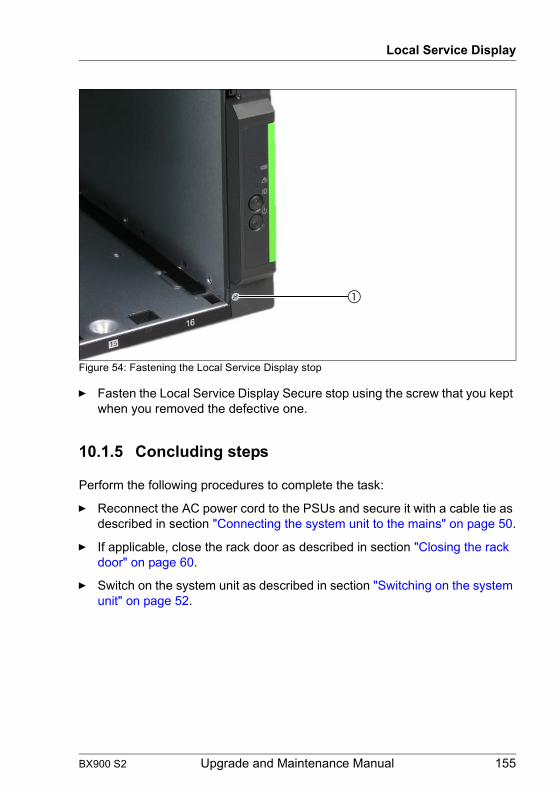
Local Service Display
Figure 54: Fastening the Local Service Display stop
Ê Fasten the Local Service Display Secure stop using the screw that you kept when you removed the defective one.
10.1.5 Concluding steps
Perform the following procedures to complete the task:
Ê Reconnect the AC power cord to the PSUs and secure it with a cable tie as described in section "Connecting the system unit to the mains" on page 50.
Ê If applicable, close the rack door as described in section "Closing the rack door" on page 60.
Ê Switch on the system unit as described in section "Switching on the system unit" on page 52.
BX900 S2 Upgrade and Maintenance Manual 155

Local Service Display
© c
ogni
tas.
Ges
ells
chft
für T
echn
ik-D
okum
enta
tion
mbH
201
1 P
fad:
C:\P
rogr
amm
e\FC
T\tim
_app
\tim
_loc
al\w
ork\
WA
LTE
R\O
BJ_
DO
KU
-136
63-0
01.fm
156 Upgrade and Maintenance Manual BX900 S2

11 Front docking boardThis chapter provides information on how to replace the front docking board.
Safety notes
V CAUTION!
● When inserting the front docking board into the system unit, ensure not to pinch or strain any connected cables.
● Circuit boards and soldered parts of internal options are exposed and can be damaged by static electricity. Always discharge static build-up (e.g. by touching a grounded object) before handling electrostatic-sensitive devices (ESDs)
● Do not touch the circuitry on boards or soldered parts. Hold circuit boards by their metallic areas or edges.
● For further information, please refer to chapter "Important information" on page 29.
Note on system information backup / restore
I The front docking board contains the Chassis ID EPROM that contains system information like system unit name and model, housing type, serial number and manufacturing data.
When you replace the front docking board you must reprogram the chassis ID PROM.
Please back up a setting value of the management blade if it is possible before exchanging the front docking board. The "User Assigned Name" of connection blade setting is not included in the backup.
After installing the new front docking board, it is necessary to program the ChassisID prom with the help of the "ChassisIDProm Tool".
This tool is available for download from the following Fujitsu Technology Solutions support page:
http://partners.ts.fujitsu.com/com/service/intelservers/tools
For the Japanese market, follow the instructions privided separately.
BX900 S2 Upgrade and Maintenance Manual 157

Front docking board
© c
ogni
tas.
Ges
ells
chft
für T
echn
ik-D
okum
enta
tion
mbH
201
1 P
fad:
C:\P
rogr
amm
e\FC
T\tim
_app
\tim
_loc
al\w
ork\
WA
LTE
R\O
BJ_
DO
KU
-136
70-0
01.fm
11.1 Basic information
Figure 55: Front docking board with LCD cable
The front docking board, together with the LCD cable, establishes the connection from the midplane of the system unit to the Local Service Display. The front docking board and the LCD cable together form a replacement unit.
Figure 56: Installation position of the front docking board
158 Upgrade and Maintenance Manual BX900 S2

Front docking board
The front docking board is attached to the side cover of the system unit next to server blade slot 16, see figure 56. The LCD cable for the Local Service Display runs through a channel in the side cover to the Local Service Display.
BX900 S2 Upgrade and Maintenance Manual 159

Front docking board
© c
ogni
tas.
Ges
ells
chft
für T
echn
ik-D
okum
enta
tion
mbH
201
1 P
fad:
C:\P
rogr
amm
e\FC
T\tim
_app
\tim
_loc
al\w
ork\
WA
LTE
R\O
BJ_
DO
KU
-136
70-0
01.fm
11.2 Replacing the front docking board
11.2.1 Required tools
● Preliminary and concluding steps: tool-less
● Replacing the front docking board:
– PH0 / (+) No. 0 screw driver
11.2.2 Preliminary steps
Before replacing the front docking board, perform the following steps:
Ê Save the management blade settings as described in section "Saving / Restoring management blade settings" on page 64.
Ê If applicable, open the rack door as described in section "Opening the rack door" on page 48.
Ê Locate the desired system unit as described in section "Locating the defective system unit" on page 45.
Ê Shut down the system unit as described in section "Shutting down the system unit" on page 49.
Ê Make sure that the server blade slots 7, 8, 15 and 16 are empty as described in section "Removing / installing server blades and storage blades" on page 54.
Ê Remove the AC power cords from the cable ties and disconnect them from the PSUs as described in section "Disconnecting the power cords" on page 49.
Field Replaceable Units (FRU)
average hardware task duration: 15 minutes
average software task duration: 15 minutes
160 Upgrade and Maintenance Manual BX900 S2

Front docking board
11.2.3 Removing the front docking board
Figure 57: Removing the Local Service Display stop
Ê Loosen the Phillips screw (1) to remove the Local Service Display stop.
Figure 58: Unlocking the front docking board
Ê Press on the touch point (arrow) to unlock the front docking board. The touch point engages in the unlocked position.
BX900 S2 Upgrade and Maintenance Manual 161

Front docking board
© c
ogni
tas.
Ges
ells
chft
für T
echn
ik-D
okum
enta
tion
mbH
201
1 P
fad:
C:\P
rogr
amm
e\FC
T\tim
_app
\tim
_loc
al\w
ork\
WA
LTE
R\O
BJ_
DO
KU
-136
70-0
01.fm
Figure 59: Removing the front docking board
Ê Place your fingers in the round recesses (1) of the front docking board and carefully remove it from its anchorage (2).
Figure 60: Removing the front docking board from the system unit
Ê Carefully remove the front docking board from the system unit as far as the LCD cable will allow.
162 Upgrade and Maintenance Manual BX900 S2

Front docking board
Figure 61: Unlocking the front docking board
Ê Slip your fingernail underneath the black clamping bracket (1) and open it up.
Ê Open the clip (2) and remove the Local Service Display connecting cable.
BX900 S2 Upgrade and Maintenance Manual 163

Front docking board
© c
ogni
tas.
Ges
ells
chft
für T
echn
ik-D
okum
enta
tion
mbH
201
1 P
fad:
C:\P
rogr
amm
e\FC
T\tim
_app
\tim
_loc
al\w
ork\
WA
LTE
R\O
BJ_
DO
KU
-136
70-0
01.fm
11.2.4 Installing the front docking board
Figure 62: Connecting the cables
Ê Connect the old LCD cable and the free end of the new LCD cable using easily removable adhesive tape (e.g. masking tape).
Figure 63: Unlocking the front docking board
Ê Carefully thread the new LCD cable in the side cover using the old LCD cable. To do this, remove the Local Service Display with the old LCD cable from the system unit.
164 Upgrade and Maintenance Manual BX900 S2

Front docking board
Figure 64: Anchoring the front docking board
Ê Make sure that the LCD cable is completely inside the side cover.
Ê Connect the front docking board to the two guide pins (1) of the midplane connector and push it forward as far as it will go. When it is in its final installation position, it clicks into place in the side cover.
Ê Pull the free end of the new LCD cable out of the system unit using the old cable.
Ê Remove the adhesive tape.
I Make sure that the connection of the two cables does not come loose when inserting the cable in the side cover.
BX900 S2 Upgrade and Maintenance Manual 165

Front docking board
© c
ogni
tas.
Ges
ells
chft
für T
echn
ik-D
okum
enta
tion
mbH
201
1 P
fad:
C:\P
rogr
amm
e\FC
T\tim
_app
\tim
_loc
al\w
ork\
WA
LTE
R\O
BJ_
DO
KU
-136
70-0
01.fm
Ê Remove the old LCD cable from the Local Service Display and connect the new one, see "Connecting cable to the Local Service Display" on page 154.
Ê Reinstall the Local Service Display as described in "Inserting the Local Service Display" on page 154.
11.2.5 Concluding steps
Perform the following procedures to complete the task:
Ê If applicable, reinstall the server blades and storage blades in their old slots as described in section "Removing / installing server blades and storage blades" on page 54.
Ê Reconnect the AC power cords to the PSUs and secure them with cable ties as described in section "Connecting the system unit to the mains" on page 50.
Ê If applicable, close the rack door as described in section "Closing the rack door" on page 60.
Ê Switch on the system unit as described in section "Switching on the system unit" on page 52.
Ê Store your system units system information on the Chassis ID EPROM integrated into the front docking board. For further information on how to obtain and use the ChassisId_Prom Tool, refer to section "Using the Chassis ID Prom Tool" on page 82.
166 Upgrade and Maintenance Manual BX900 S2
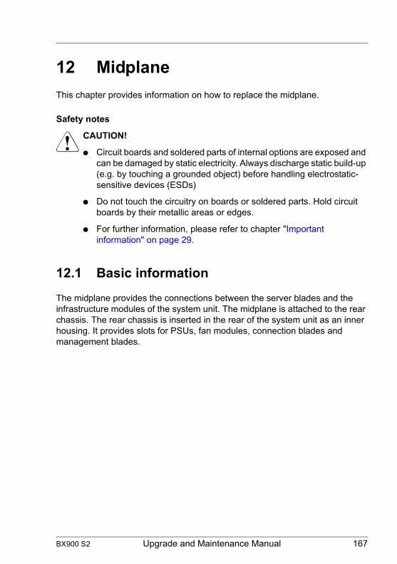
12 MidplaneThis chapter provides information on how to replace the midplane.
Safety notes
V CAUTION!
● Circuit boards and soldered parts of internal options are exposed and can be damaged by static electricity. Always discharge static build-up (e.g. by touching a grounded object) before handling electrostatic-sensitive devices (ESDs)
● Do not touch the circuitry on boards or soldered parts. Hold circuit boards by their metallic areas or edges.
● For further information, please refer to chapter "Important information" on page 29.
12.1 Basic information
The midplane provides the connections between the server blades and the infrastructure modules of the system unit. The midplane is attached to the rear chassis. The rear chassis is inserted in the rear of the system unit as an inner housing. It provides slots for PSUs, fan modules, connection blades and management blades.
BX900 S2 Upgrade and Maintenance Manual 167

Midplane
© c
ogni
tas.
Ges
ells
chft
für T
echn
ik-D
okum
enta
tion
mbH
201
1 P
fad:
C:\P
rogr
amm
e\FC
T\tim
_app
\tim
_loc
al\w
ork\
WA
LTE
R\O
BJ_
DO
KU
-136
69-0
01.fm
Figure 65: Rear chassis with midplane
The removed rear chassis with the attached midplane is shown in figure 65. You can see the contacts for the server blades (1) at the top and bottom of the midplane. The port for the front docking board (2) is on the right of the midplane. The front docking board is connected to the Local Service Display by a cable.
168 Upgrade and Maintenance Manual BX900 S2

Midplane
12.2 Replacing the midplane
12.2.1 Required tools
● Preliminary and concluding steps: tool-less
● Replacing the midplane:
– Phillips PH2 / (+) No. 2 screw driver
12.2.2 Preliminary steps
Before replacing the midplane, perform the following steps:
Ê If applicable, open the rack door as described in section "Opening the rack door" on page 48.
Ê Locate the desired system unit as described in section "Determining the error class" on page 45.
Ê Shut down the system unit as described in section "Shutting down the system unit" on page 49.
Ê Make a note of the positions of the individual server blades and storage blades, the connection blades, PSUs, fan modules and dummy modules in the system unit for reinstallation.
Ê Remove the AC power cords from the cable ties and disconnect them from the PSUs as described in section "Disconnecting the power cords" on page 49.
Ê Remove all server blades and storage blades from the system unit as described in section "Removing / installing server blades and storage blades" on page 54.
Ê Disconnect the cables from the connection blades.
Field Replaceable Units (FRU)
Average task duration: 55 minutes
BX900 S2 Upgrade and Maintenance Manual 169

Midplane
© c
ogni
tas.
Ges
ells
chft
für T
echn
ik-D
okum
enta
tion
mbH
201
1 P
fad:
C:\P
rogr
amm
e\FC
T\tim
_app
\tim
_loc
al\w
ork\
WA
LTE
R\O
BJ_
DO
KU
-136
69-0
01.fm
Ê If applicable, remove SFP transceiver modules from the connection blade as described in section "Removing an SFP+ transceiver module" on page 133.
Ê Remove all connection blades from the system unit as described in section "Removing single-width connection blades" on page 115 and "Removing double-width connection blades" on page 123.
Ê Remove the PSUs and fan modules from the system unit as described in sections "Removing the power supply unit" on page 96 and "Removing the fan unit" on page 102.
Ê Remove the management blades. This is done in the same way as described in section "Removing single-width connection blades" on page 115.
12.2.3 Removing the rear chassis
Figure 66: Loosening the fixing screws of the rear chassis
Ê Loosen the fixing screws that fasten the rear chassis to the system unit.
170 Upgrade and Maintenance Manual BX900 S2

Midplane
Figure 67: Removing the rear chassis from the system unit
Ê Take the rear chassis by the handles (1) and carefully pull it out of the system unit until the handle openings (2) are outside the system unit completely. The rear chassis engages in this position.
Figure 68: Releasing the locking mechanism of the rear chassis
BX900 S2 Upgrade and Maintenance Manual 171
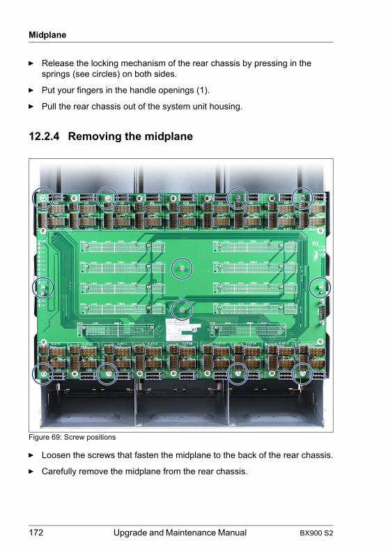
Midplane
© c
ogni
tas.
Ges
ells
chft
für T
echn
ik-D
okum
enta
tion
mbH
201
1 P
fad:
C:\P
rogr
amm
e\FC
T\tim
_app
\tim
_loc
al\w
ork\
WA
LTE
R\O
BJ_
DO
KU
-136
69-0
01.fm
Ê Release the locking mechanism of the rear chassis by pressing in the springs (see circles) on both sides.
Ê Put your fingers in the handle openings (1).
Ê Pull the rear chassis out of the system unit housing.
12.2.4 Removing the midplane
Figure 69: Screw positions
Ê Loosen the screws that fasten the midplane to the back of the rear chassis.
Ê Carefully remove the midplane from the rear chassis.
172 Upgrade and Maintenance Manual BX900 S2
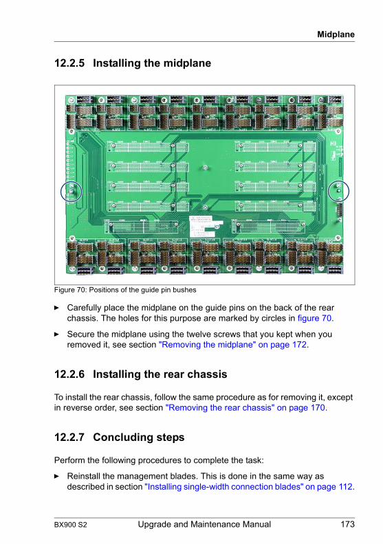
Midplane
12.2.5 Installing the midplane
Figure 70: Positions of the guide pin bushes
Ê Carefully place the midplane on the guide pins on the back of the rear chassis. The holes for this purpose are marked by circles in figure 70.
Ê Secure the midplane using the twelve screws that you kept when you removed it, see section "Removing the midplane" on page 172.
12.2.6 Installing the rear chassis
To install the rear chassis, follow the same procedure as for removing it, except in reverse order, see section "Removing the rear chassis" on page 170.
12.2.7 Concluding steps
Perform the following procedures to complete the task:
Ê Reinstall the management blades. This is done in the same way as described in section "Installing single-width connection blades" on page 112.
BX900 S2 Upgrade and Maintenance Manual 173

Midplane
© c
ogni
tas.
Ges
ells
chft
für T
echn
ik-D
okum
enta
tion
mbH
201
1 P
fad:
C:\P
rogr
amm
e\FC
T\tim
_app
\tim
_loc
al\w
ork\
WA
LTE
R\O
BJ_
DO
KU
-136
69-0
01.fm
Ê Reinstall the connection blades as described in section "Installing single-width connection blades" on page 112 and "Installing double-width connection blades" on page 119.
Ê Reinstall the PSUs and fan modules in their old bays as described in "Installing a power supply unit" on page 94 and "Installing the fan module" on page 100.
Ê Reinstall the server blades and storage blades in their old slots as described in section "Removing / installing server blades and storage blades" on page 54.
Ê Reconnect the data cables to the connection blades.
Ê Reconnect the AC power cords to the PSUs and secure them with cable ties as described in section "Connecting the system unit to the mains" on page 50.
Ê Reinstall the server blades and storage blades in their old slots as described in section "Removing / installing server blades and storage blades" on page 54.
Ê If applicable, close the rack door as described in section "Closing the rack door" on page 60.
Ê Switch on the system unit as described in section "Switching on the system unit" on page 52.
174 Upgrade and Maintenance Manual BX900 S2
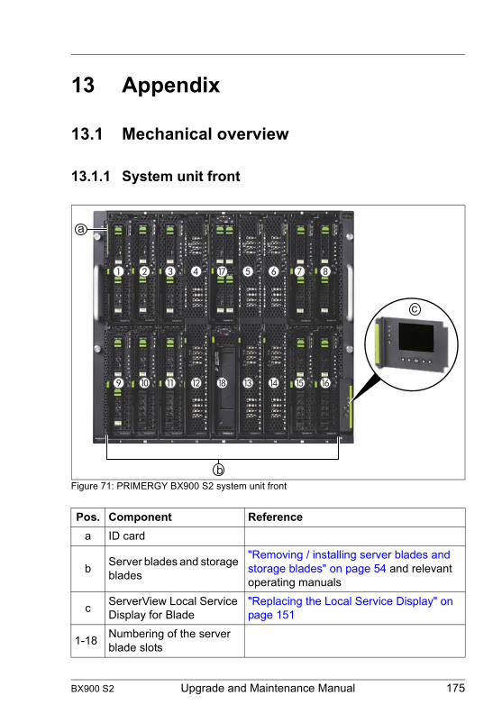
13 Appendix
13.1 Mechanical overview
13.1.1 System unit front
Figure 71: PRIMERGY BX900 S2 system unit front
Pos. Component Referencea ID card
b Server blades and storage blades
"Removing / installing server blades and storage blades" on page 54 and relevant operating manuals
c ServerView Local Service Display for Blade
"Replacing the Local Service Display" on page 151
1-18 Numbering of the server blade slots
c
b
a
BX900 S2 Upgrade and Maintenance Manual 175

Appendix
© c
ogni
tas.
Ges
ells
chft
für T
echn
ik-D
okum
enta
tion
mbH
201
1 P
fad:
C:\P
rogr
amm
e\FC
T\tim
_app
\tim
_loc
al\w
ork\
WA
LTE
R\O
BJ_
DO
KU
-136
68-0
01.fm
13.1.2 System unit rear
Figure 72: PRIMERGY BX900 S2 system unit rear
Pos. Component Reference
PSU 1-6 PSUs and fan modules"Replacing a power supply unit" on page 95, "Replacing a fan module" on page 99
CB 1-8 Connection blades
"Replacing single-width connection blades" on page 117, "Installing double-width connection blades" on page 119
MMB 1, 2 Management blades "Replacing a management blade" on page 146
PSU 1
CB 1 CB 2CB 3 CB 4CB 5 CB 6CB 7 CB 8
MMB 1 MMB 2
PSU 2 PSU 3
PSU 4 PSU 5 PSU 6
176 Upgrade and Maintenance Manual BX900 S2

Appendix
13.1.3 System unit interior
Midplane
Figure 73: Midplane
Pos. Component Reference1 Server blade connectors
"Replacing the midplane" on page 1692 Front docking board
connector
BX900 S2 Upgrade and Maintenance Manual 177
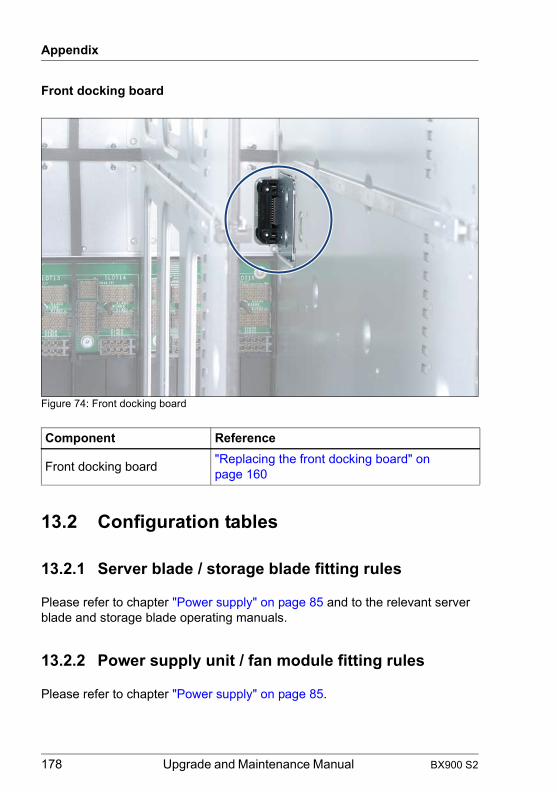
Appendix
© c
ogni
tas.
Ges
ells
chft
für T
echn
ik-D
okum
enta
tion
mbH
201
1 P
fad:
C:\P
rogr
amm
e\FC
T\tim
_app
\tim
_loc
al\w
ork\
WA
LTE
R\O
BJ_
DO
KU
-136
68-0
01.fm
Front docking board
Figure 74: Front docking board
13.2 Configuration tables
13.2.1 Server blade / storage blade fitting rules
Please refer to chapter "Power supply" on page 85 and to the relevant server blade and storage blade operating manuals.
13.2.2 Power supply unit / fan module fitting rules
Please refer to chapter "Power supply" on page 85.
Component Reference
Front docking board "Replacing the front docking board" on page 160
178 Upgrade and Maintenance Manual BX900 S2
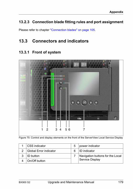
Appendix
13.2.3 Connection blade fitting rules and port assignment
Please refer to chapter "Connection blades" on page 105.
13.3 Connectors and indicators
13.3.1 Front of system
Figure 75: Control and display elements on the front of the ServerView Local Service Display
1 CSS indicator 5 power indicator2 Global Error indicator 6 ID indicator3 ID button 7 Navigation buttons for the Local
Service Display4 On/Off button
1 2 3 4 5 6 7
BX900 S2 Upgrade and Maintenance Manual 179

Appendix
© c
ogni
tas.
Ges
ells
chft
für T
echn
ik-D
okum
enta
tion
mbH
201
1 P
fad:
C:\P
rogr
amm
e\FC
T\tim
_app
\tim
_loc
al\w
ork\
WA
LTE
R\O
BJ_
DO
KU
-136
68-0
01.fm
Figure 76: ServerView Local Service Display
The control elements and indicators can also be found on the front of the Local Service Display. This means they are also available when it is folded away.
I The control and display elements of the server blades and storage blades are described in the relevant operating manuals.
13.3.1.1 Control elements on the Local Service Display
On/Off button
When the system is switched off, it can be switched on again by pressing the On/Off button.
When the system is operating, pressing the On/Off button will switch off the system.
V CAUTION!
Risk of loss of data!
I The On/Off button does not disconnect the server from the mains voltage. To disconnect from the mains completely, remove the power plug(s).
ID ID button
Lights up (blue) on the front and on the rear of the system unit when the ID button is pressed. The two ID indicators are synchronized.
180 Upgrade and Maintenance Manual BX900 S2
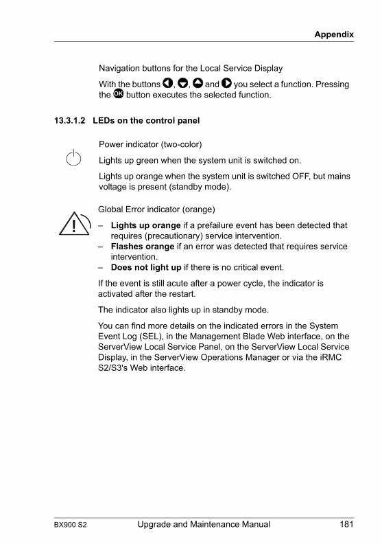
Appendix
13.3.1.2 LEDs on the control panel
Navigation buttons for the Local Service Display
With the buttons , , and you select a function. Pressing the button executes the selected function.
Power indicator (two-color)
Lights up green when the system unit is switched on.
Lights up orange when the system unit is switched OFF, but mains voltage is present (standby mode).
Global Error indicator (orange)
– Lights up orange if a prefailure event has been detected that requires (precautionary) service intervention.
– Flashes orange if an error was detected that requires service intervention.
– Does not light up if there is no critical event.
If the event is still acute after a power cycle, the indicator is activated after the restart.
The indicator also lights up in standby mode.
You can find more details on the indicated errors in the System Event Log (SEL), in the Management Blade Web interface, on the ServerView Local Service Panel, on the ServerView Local Service Display, in the ServerView Operations Manager or via the iRMC S2/S3's Web interface.
!
BX900 S2 Upgrade and Maintenance Manual 181
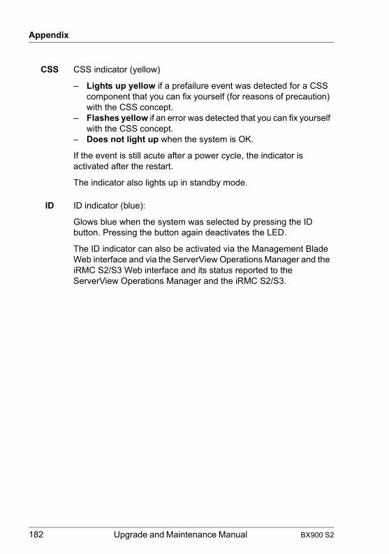
Appendix
© c
ogni
tas.
Ges
ells
chft
für T
echn
ik-D
okum
enta
tion
mbH
201
1 P
fad:
C:\P
rogr
amm
e\FC
T\tim
_app
\tim
_loc
al\w
ork\
WA
LTE
R\O
BJ_
DO
KU
-136
68-0
01.fm
CSS CSS indicator (yellow)
– Lights up yellow if a prefailure event was detected for a CSS component that you can fix yourself (for reasons of precaution) with the CSS concept.
– Flashes yellow if an error was detected that you can fix yourself with the CSS concept.
– Does not light up when the system is OK.
If the event is still acute after a power cycle, the indicator is activated after the restart.
The indicator also lights up in standby mode.
ID ID indicator (blue):
Glows blue when the system was selected by pressing the ID button. Pressing the button again deactivates the LED.
The ID indicator can also be activated via the Management Blade Web interface and via the ServerView Operations Manager and the iRMC S2/S3 Web interface and its status reported to the ServerView Operations Manager and the iRMC S2/S3.
182 Upgrade and Maintenance Manual BX900 S2

Appendix
13.3.2 Back of system
13.3.2.1 Connectors on the management blade
Figure 77: Connectors on the management blade
I The service LAN port and the LAN ports for blade server management must be in different LAN subnetworks.
It is recommended to operate the management blade user interface in a separate broadcast domain for the server management.
1 Service LAN port (as a point-to-point connection, for system unit administration only, no access to server blades and connection blades)
2 USB ports for backing up and restoring the MMB configuration and for access to logging information
3 Serial port for a local management console4,5 LAN ports for blade server management (including server blades and
connection blades). Customers must use the Up port (4) while the Down port (5) is reserved for service personnel.
1 2 3 4 5
BX900 S2 Upgrade and Maintenance Manual 183
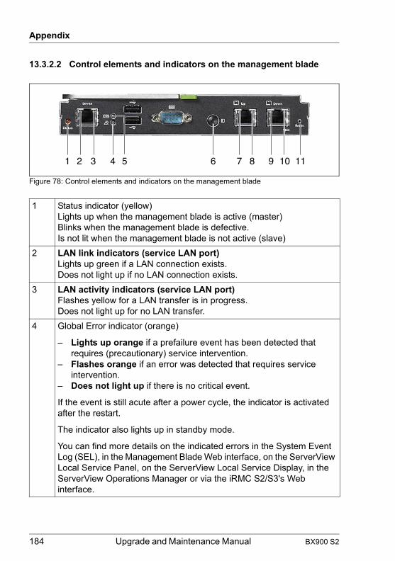
Appendix
© c
ogni
tas.
Ges
ells
chft
für T
echn
ik-D
okum
enta
tion
mbH
201
1 P
fad:
C:\P
rogr
amm
e\FC
T\tim
_app
\tim
_loc
al\w
ork\
WA
LTE
R\O
BJ_
DO
KU
-136
68-0
01.fm
13.3.2.2 Control elements and indicators on the management blade
Figure 78: Control elements and indicators on the management blade
1 Status indicator (yellow)Lights up when the management blade is active (master)Blinks when the management blade is defective.Is not lit when the management blade is not active (slave)
2 LAN link indicators (service LAN port)Lights up green if a LAN connection exists.Does not light up if no LAN connection exists.
3 LAN activity indicators (service LAN port)Flashes yellow for a LAN transfer is in progress.Does not light up for no LAN transfer.
4 Global Error indicator (orange)
– Lights up orange if a prefailure event has been detected that requires (precautionary) service intervention.
– Flashes orange if an error was detected that requires service intervention.
– Does not light up if there is no critical event.
If the event is still acute after a power cycle, the indicator is activated after the restart.
The indicator also lights up in standby mode.
You can find more details on the indicated errors in the System Event Log (SEL), in the Management Blade Web interface, on the ServerView Local Service Panel, on the ServerView Local Service Display, in the ServerView Operations Manager or via the iRMC S2/S3's Web interface.
1 2 3 4 5 6 7 8 9 10 11
184 Upgrade and Maintenance Manual BX900 S2

Appendix
5 CSS indicator (yellow)
– Lights up yellow if a prefailure event was detected for a CSS component that you can fix yourself (for reasons of precaution) with the CSS concept.
– Flashes yellow if an error was detected that you can fix yourself with the CSS concept.
– Does not light up when the system is OK.
If the event is still acute after a power cycle, the indicator is activated after the restart.
The indicator also lights up in standby mode.6 Identification (ID) button with ID indicators (blue)
ID indicators on the front and rear of the server light up when the ID button is pressed. The two ID indicators are synchronized. To deactivate, press the button again.
The ID indicator can also be activated via ServerView Operations Manager and the Management Blade Web interface; its status is reported to ServerView Operations Manager and the Management Blade.
7, 9 LAN link indicators (Management LAN ports)Lights up green if a LAN connection exists.Does not light up if no LAN connection exists.
8, 10 LAN activity indicators (Management LAN ports)Flashes yellow when a LAN transfer is in progress.Does not light up if no LAN transfer.
11 Reset button
BX900 S2 Upgrade and Maintenance Manual 185
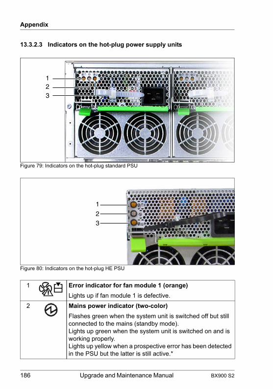
Appendix
© c
ogni
tas.
Ges
ells
chft
für T
echn
ik-D
okum
enta
tion
mbH
201
1 P
fad:
C:\P
rogr
amm
e\FC
T\tim
_app
\tim
_loc
al\w
ork\
WA
LTE
R\O
BJ_
DO
KU
-136
68-0
01.fm
13.3.2.3 Indicators on the hot-plug power supply units
Figure 79: Indicators on the hot-plug standard PSU
Figure 80: Indicators on the hot-plug HE PSU
1 Error indicator for fan module 1 (orange)Lights up if fan module 1 is defective.
2 Mains power indicator (two-color)Flashes green when the system unit is switched off but still connected to the mains (standby mode).Lights up green when the system unit is switched on and is working properly.Lights up yellow when a prospective error has been detected in the PSU but the latter is still active.*
123
1
23
186 Upgrade and Maintenance Manual BX900 S2

Appendix
13.3.2.4 Indicators on the fan modules
Figure 81: Indicators on fan module
3 Error indicator for fan module 2 (orange)Lights up if fan module 2 is defective.
* The following events are detected as predictable errors:
The temperature is very high.The power consumption is very high.The current strength is very high.
1 Error indicator for fan unit 1 (orange)Lights up if fan unit 1 is defective.
2 Power indicatorFlashes green when the system unit is switched off but still connected to the mains (standby mode).Lights up green when the system unit is switched on and the fan module is working properly.
3 Error indicator for fan unit 2 (orange)Lights up if fan unit 2 is defective.
1 2 3
BX900 S2 Upgrade and Maintenance Manual 187
Appendix
© c
ogni
tas.
Ges
ells
chft
für T
echn
ik-D
okum
enta
tion
mbH
201
1 P
fad:
C:\P
rogr
amm
e\FC
T\tim
_app
\tim
_loc
al\w
ork\
WA
LTE
R\O
BJ_
DO
KU
-136
68-0
01.fm
13.3.3 Indicators and connectors of the connection blades
13.3.3.1 Connection Blade GbE Switch/IBP 18/6 (SB6)
Figure 82: Connection Blade GbE Switch/IBP 18/6
1 Status indicator (green/orange)
Lights up green: Power supply is supplied to the connection blade
Lights up orange:
Switch error
Dark: Power supply is not supplied to the connection blade
2 ID indicator (blue)
Lit: ID indicator was activated via the management blade
Dark: Normal operation
A 1-Gbit Ethernet ports (RJ45 with two integrated LAN status LEDs each)
3 LAN transfer rate (green/orange)
Lights up orange:
LAN transfer rate 1 Gbit/s
Lights up green: LAN transfer rate 100 Mbit/s
Dark: LAN transfer rate 10 Mbit/s
4 LAN connection indicator (green)
Lit: LAN connection available
Flashes: LAN connection active
Dark: LAN connection unavailable or deactivated
1 2 3 4
A
188 Upgrade and Maintenance Manual BX900 S2

Appendix
13.3.3.2 Connection Blade GbE Switch/IBP 36/12 (SB11A)
Figure 83: Connection Blade GbE Switch/IBP 36/12
1 ID indicator (blue)
Lit: ID indicator was activated via the management blade
Dark: Normal operation
2 Status indicator (green/orange)
Lights up green: power supply is supplied to the connection blade.Dark: power supply is not supplied to the connection blade.
Lights up orange:
Switch error
Dark: Power supply interrupted
A 1-Gbit Ethernet ports for SFP modules for connecting fiber-optic or copper cables (4x, with two integrated status LEDs each)
3 (ERR) Error indicator (orange)
Dark: No SFP+ transceiver error
Lit: SFP transceiver error
Flashes: SFP module not supported
4 (LINK) LAN connection indicator (green)
Lit: SFP transceiver connection available
Flashes: SFP transceiver connection active
Dark: SFP transceiver connection not available or deactivated
1 2
3 4 5 6
A B
BX900 S2 Upgrade and Maintenance Manual 189

Appendix
© c
ogni
tas.
Ges
ells
chft
für T
echn
ik-D
okum
enta
tion
mbH
201
1 P
fad:
C:\P
rogr
amm
e\FC
T\tim
_app
\tim
_loc
al\w
ork\
WA
LTE
R\O
BJ_
DO
KU
-136
68-0
01.fm
B 1-Gbit Ethernet ports (8x, RJ45 with two integrated LAN status LEDs each)
5 LAN transfer rate (green/orange)
Lights up orange:
LAN transfer rate 1 Gbit/s
Lights up green: LAN transfer rate 100 Mbit/s
Dark: LAN transfer rate 10 Mbit/s
6 LAN connection indicator (green)
Lit: LAN connection available
Flashes: LAN connection active
Dark: LAN connection unavailable or deactivated
190 Upgrade and Maintenance Manual BX900 S2
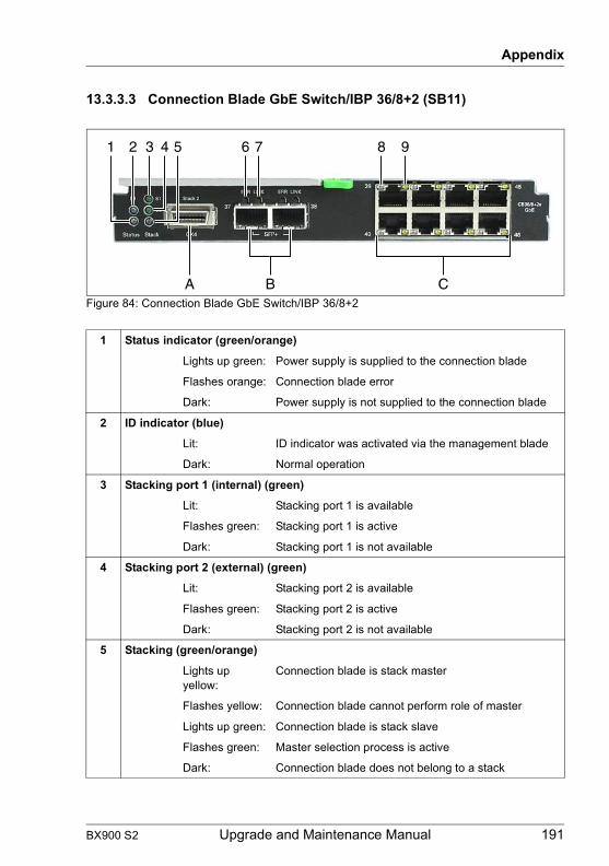
Appendix
13.3.3.3 Connection Blade GbE Switch/IBP 36/8+2 (SB11)
Figure 84: Connection Blade GbE Switch/IBP 36/8+2
1 Status indicator (green/orange)
Lights up green: Power supply is supplied to the connection blade
Flashes orange: Connection blade error
Dark: Power supply is not supplied to the connection blade
2 ID indicator (blue)
Lit: ID indicator was activated via the management blade
Dark: Normal operation
3 Stacking port 1 (internal) (green)
Lit: Stacking port 1 is available
Flashes green: Stacking port 1 is active
Dark: Stacking port 1 is not available
4 Stacking port 2 (external) (green)
Lit: Stacking port 2 is available
Flashes green: Stacking port 2 is active
Dark: Stacking port 2 is not available
5 Stacking (green/orange)
Lights up yellow:
Connection blade is stack master
Flashes yellow: Connection blade cannot perform role of master
Lights up green: Connection blade is stack slave
Flashes green: Master selection process is active
Dark: Connection blade does not belong to a stack
1 2 3 4 5 6 7 8 9
A B C
BX900 S2 Upgrade and Maintenance Manual 191

Appendix
© c
ogni
tas.
Ges
ells
chft
für T
echn
ik-D
okum
enta
tion
mbH
201
1 P
fad:
C:\P
rogr
amm
e\FC
T\tim
_app
\tim
_loc
al\w
ork\
WA
LTE
R\O
BJ_
DO
KU
-136
68-0
01.fm
A HiGig/HiGig+ connection (CX4) for stacking (2x), for detailed information see section "Connection blade stacking" on page 137.
B 10-Gbit Ethernet ports for SFP+ modules for connecting fiber-optic or copper cables (with two integrated status LEDs each)
6 (ERR) Error indicator (orange)
Dark: No SFP+ transceiver error
Lit: SFP+ transceiver error
Flashes: SFP+ module not supported
7 (LINK) LAN connection indicator (green)
Lit: SFP+ transceiver connection available
Flashes: SFP+ transceiver connection active
Dark: SFP+ transceiver connection not available or deactivated.
C 1-Gbit Ethernet ports (RJ45 with two integrated LAN status LEDs each)
8 LAN transfer rate (green/orange)
Lights up orange:
LAN transfer rate 1 Gbit/s
Lights up green: LAN transfer rate 100 Mbit/s
Dark: LAN transfer rate 10 Mbit/s
9 LAN connection indicator (green)
Lit: LAN connection available
Flashes: LAN connection active
Dark: LAN connection unavailable or deactivated
192 Upgrade and Maintenance Manual BX900 S2

Appendix
13.3.3.4 Connection Blade 10 GbE Switch/IBP 18/8
Figure 85: Connection Blade 10 GbE Switch/IBP 18/8
1 Status indicator (green/orange)
Lit green: Power supply is supplied to the connection blade
Flashes alternately green/orange:
Connection blade error
Dark: Power supply is not supplied to the connection blade
2 Stack indicator (green/yellow) (future use)
Lit yellow: Operating as a stack master
Flashes yellow: Operating failure as a stack master
Lit green: Operating as a stack slave
Flashes green Operating failure as a stack slave or during master election process
Dark: No stacking
3 ID indicator (blue)
Lit: ID indicator was activated via the management blade
Dark: Normal operation
6 Reset button
1 2 3 4 5
A 6
BX900 S2 Upgrade and Maintenance Manual 193

Appendix
© c
ogni
tas.
Ges
ells
chft
für T
echn
ik-D
okum
enta
tion
mbH
201
1 P
fad:
C:\P
rogr
amm
e\FC
T\tim
_app
\tim
_loc
al\w
ork\
WA
LTE
R\O
BJ_
DO
KU
-136
68-0
01.fm
A 10-Gbit Ethernet ports for SFP+ modules for connection of fiber-optic cables or for active twinax copper cables (8x, each with two integrated status LEDs)
4 (ERR) Error indicator (orange)
Dark: No SFP+ module error or SFP+ module not installed
Lit: SFP+ module error
Flashes: SFP+ module not supported
5 (LINK) LAN connection indicator (green)
Lit: LAN connection available
Flashes: LAN connection active
Dark: LAN connection unavailable or deactivated
194 Upgrade and Maintenance Manual BX900 S2
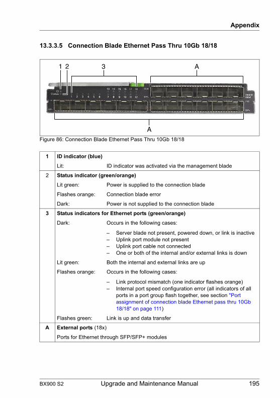
Appendix
13.3.3.5 Connection Blade Ethernet Pass Thru 10Gb 18/18
Figure 86: Connection Blade Ethernet Pass Thru 10Gb 18/18
1 ID indicator (blue)
Lit: ID indicator was activated via the management blade
2 Status indicator (green/orange)
Lit green: Power is supplied to the connection blade
Flashes orange: Connection blade error
Dark: Power is not supplied to the connection blade
3 Status indicators for Ethernet ports (green/orange)
Dark: Occurs in the following cases:
– Server blade not present, powered down, or link is inactive– Uplink port module not present– Uplink port cable not connected– One or both of the internal and/or external links is down
Lit green: Both the internal and external links are up
Flashes orange: Occurs in the following cases:
– Link protocol mismatch (one indicator flashes orange)– Internal port speed configuration error (all indicators of all
ports in a port group flash together, see section "Port assignment of connection blade Ethernet pass thru 10Gb 18/18" on page 111)
Flashes green: Link is up and data transfer
A External ports (18x)
Ports for Ethernet through SFP/SFP+ modules
1 2
A
A3
BX900 S2 Upgrade and Maintenance Manual 195

Appendix
© c
ogni
tas.
Ges
ells
chft
für T
echn
ik-D
okum
enta
tion
mbH
201
1 P
fad:
C:\P
rogr
amm
e\FC
T\tim
_app
\tim
_loc
al\w
ork\
WA
LTE
R\O
BJ_
DO
KU
-136
68-0
01.fm
13.3.3.6 Connection Blade 8Gb FC Switch 18/8
Figure 87: 8-Gb FC Switch Connection Blade 18/8
1ID
ID indicator (blue)
Lit: ID indicator was activated via the management blade
2 Health indicator (green/orange)
Controlled by the management blade
3 Reset button
4 Status indicator (green/orange)
Dark: Connection blade is not running or is defective
Lights up green: Connection blade is running
Lights up orange: Boot phase; one or more ports are offline; restarting connection
Flashes orange/green:
Warning: An error has occurred.
The LED can also flash during a test.
A External FC ports (8x)
Ports for FC SFP Multi-Mode (MMF) or FC SFP+ Multi-Mode (MMF) SFP modules
B Status indicators for external FC ports (green/orange)
Dark: No signal reception
Flickers green: FC port online, data transport
Flashes green: – Slow: FC port online, but segmented– Fast: Internal loop
Lights up orange: Signal reception, but not online
Flashes orange: Slow (~ 2 sec. interval): FC port deactivated.
Fast (~ 0.5 sec. interval): FC port defective
C Management LAN port
1 2 3 CA
B
4
196 Upgrade and Maintenance Manual BX900 S2

Appendix
13.3.3.7 Connection Blade 8Gb FC Pass Thru 18/18
Figure 88: 8-Gb FC Pass Thru Connection Blade 18/18
1ID
ID indicator (blue)
Lit: ID indicator was activated via the management blade
2 Status indicator (green/orange)
Dark: Connection blade is powered off
Lights up green: Connection blade is powered on, status OK
Flashes orange: Connection blade is powered on, status fail
3 Status indicators for external FC ports (green)
Lit: FC link up
A, B External FC ports (A: 1-12, B: 13-18, from left to right)
Ports for FC SFP Multi-Mode (MMF) 4Gbit/s or FC SFP+ Multi-Mode (MMF) 8Gbit/s
1 2 3
A
B
BX900 S2 Upgrade and Maintenance Manual 197

Appendix
© c
ogni
tas.
Ges
ells
chft
für T
echn
ik-D
okum
enta
tion
mbH
201
1 P
fad:
C:\P
rogr
amm
e\FC
T\tim
_app
\tim
_loc
al\w
ork\
WA
LTE
R\O
BJ_
DO
KU
-136
68-0
01.fm
13.3.3.8 Connection Blade DCB SW 10Gb 18/6+6
Figure 89: Connection Blade DCB SW 10Gb 18/6+6
A External 10 Gb Ethernet ports (6x)
Ports for Brocade branded Ethernet SFP+ 10 Gbit/s modules or SFP+ Twinax cables
B External 8 Gb FC ports (6x)
Ports for Brocade branded FC SFP+ 8Gbit/s modules or SFP 4Gbit/s modules
1 Status indicators for external Ethernet ports (green/orange)
Dark: No signal carrier
Lights up green: Link is established and port is active. Online is normal, but no port activity.
Flickers green: Port online, data transport
Flashes green: – Slow: Port online, but segmented– Fast: Internal loop
Lights up orange: Port with no sync (light or signal carrier issue)
Flashes orange: Slow (~ 2 sec. interval): Port deactivated.
Fast (~ 0.5 sec. interval): Port defective
2 Status indicators for external FC ports (green/orange)
Dark: No signal carrier
Lit green: Link is established and port is active. Online is normal, but no port activity.
Flickers green: Port online, data transport
Flashes green: – Slow: Port online, but segmented– Fast: Internal loop
Lights up orange: Port with no sync (light or signal carrier issue)
Flashes orange: Slow (~ 2 sec. interval): Port deactivated.
Fast (~ 0.5 sec. interval): Port defective
1
3 4 5 6
A B
2
198 Upgrade and Maintenance Manual BX900 S2

Appendix
3ID
ID indicator (blue)
Lit: ID indicator was activated via the management blade
4 Health indicator (green/orange)
Dark: Connection blade is powered off or power has failed
Lights up green: Connection blade is running
Flashes orange Connection blade has failed
5 Status indicator (green/orange)
Dark: Connection blade is shut down and powered off normally
Lights up green: Connection blade is running
Flashes green Boot phase; connection blade is running diagnostics and initialization programs
Flashes orange: Warning: Critical failures have occured (e.g. The temperature has risen the normal thermal threshold. The switch continues operating.)
Lights up orange: Warning: Fatal failures have occured. (Serious problem detected; the switch is powered off.)
6 Reset button
Press the reset button for up to five seconds to reboot the connection blade
BX900 S2 Upgrade and Maintenance Manual 199

Appendix
© c
ogni
tas.
Ges
ells
chft
für T
echn
ik-D
okum
enta
tion
mbH
201
1 P
fad:
C:\P
rogr
amm
e\FC
T\tim
_app
\tim
_loc
al\w
ork\
WA
LTE
R\O
BJ_
DO
KU
-136
68-0
01.fm
13.3.3.9 Connection Blade FEX B22F 10Gb (Cisco)
Figure 90: Connection Blade FEX B22F 10Gb (Cisco)
A External 10GbE ports (8x) to connect to the Nexus parent switch
Ports for Cisco branded copper Twinax cables, Fabric Extender Transceivers (FET), or other standard 10 Gigabit Ethernet optics such as 10Gbase-SR, 10Gbase-LR, and 10Gbase-ER
B Service port (only for diagnostic purposes)
1ID
ID indicator (blue)
Lit: ID indicator was activated via the management blade
2 Status indicator (green)
Dark: Connection blade is not running or is defective
Lights up green: Connection blade is running
3 Status indicators for external ports (green/orange)
Dark: No signal reception
Lights up green: Link is established
Lights up orange: Port is administratively disabled.
Flashes orange: Port is defective.
1 2
A B
3
200 Upgrade and Maintenance Manual BX900 S2
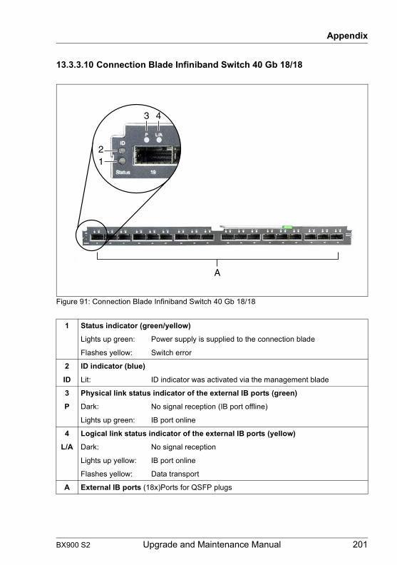
Appendix
13.3.3.10 Connection Blade Infiniband Switch 40 Gb 18/18
Figure 91: Connection Blade Infiniband Switch 40 Gb 18/18
1 Status indicator (green/yellow)
Lights up green: Power supply is supplied to the connection blade
Flashes yellow: Switch error
2 ID indicator (blue)
ID Lit: ID indicator was activated via the management blade
3 Physical link status indicator of the external IB ports (green)
P Dark: No signal reception (IB port offline)
Lights up green: IB port online
4 Logical link status indicator of the external IB ports (yellow)
L/A Dark: No signal reception
Lights up yellow: IB port online
Flashes yellow: Data transport
A External IB ports (18x)Ports for QSFP plugs
3 4
12
A
BX900 S2 Upgrade and Maintenance Manual 201

Appendix
© c
ogni
tas.
Ges
ells
chft
für T
echn
ik-D
okum
enta
tion
mbH
201
1 P
fad:
C:\P
rogr
amm
e\FC
T\tim
_app
\tim
_loc
al\w
ork\
WA
LTE
R\O
BJ_
DO
KU
-136
68-0
01.fm
13.3.3.11 Connection Blade Infiniband Switch 56 Gb 18/18 FDR
Figure 92: Connection Blade Infiniband Switch 56 Gb 18/18 FDR
1 Status indicator (green/yellow)
Lights up green: Power supply is supplied to the connection blade
Flashes yellow: Switch error
2 ID indicator (blue)
ID Lit: ID indicator was activated via the management blade
3 Physical link status indicator of the external IB ports (green)
P Dark: No signal reception (IB port offline)
Lights up green: IB port online
4 Logical link status indicator of the external IB ports (yellow)
L/A Dark: No signal reception
Lights up yellow: IB port online
Flashes yellow: Data transport
A External IB ports (18x) Ports for QSFP plugs
B External Debug port
43
12
A AB
202 Upgrade and Maintenance Manual BX900 S2

Appendix
13.3.3.12 Connection Blade SAS Switch 6 Gb 18/6
Figure 93: Connection Blade SAS Switch 6 Gb 18/6
1 Status indicator (green/orange)
Lights up green: Power supply is supplied to the connection blade
Lights up orange:
Switch error
Dark: Power supply is not supplied to the connection blade
2 ID indicator (blue)
Lit: ID indicator was activated via the management blade
Dark: Normal operation
3 Reset button
A 6-Gbit SAS connectors (6x)
1 2 3
A
BX900 S2 Upgrade and Maintenance Manual 203

Appendix
© c
ogni
tas.
Ges
ells
chft
für T
echn
ik-D
okum
enta
tion
mbH
201
1 P
fad:
C:\P
rogr
amm
e\FC
T\tim
_app
\tim
_loc
al\w
ork\
WA
LTE
R\O
BJ_
DO
KU
-136
68-0
01.fm
13.4 Management Blade Settings
Figure 94: Management Blade DIP switch (a)
The management blade is delivered with the DIP switches set in the following positions:
Switch Function Default
1 Flash Swap - activates the second management blade boot ROM. The second boot ROM can be used as reserve, if a management blade firmware update has failed.
OFF
2 Recovery Mode - firmware update OFF
3 Default Set - loads the standard management blade configuration (IP address, password, ...)
OFF
4 Clear Password - clear user defined password OFF
5 Diagnostic Mode - activates the diagnostic mode OFF
6 Not defined OFF
a
204 Upgrade and Maintenance Manual BX900 S2
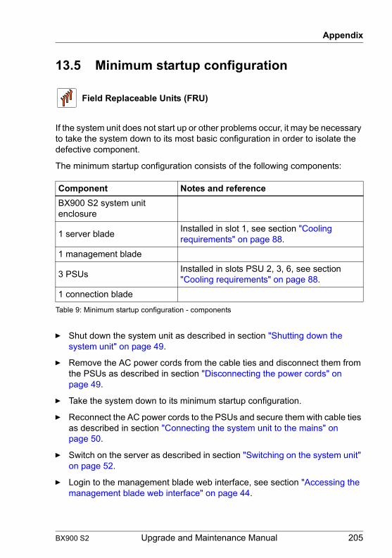
Appendix
13.5 Minimum startup configuration
If the system unit does not start up or other problems occur, it may be necessary to take the system down to its most basic configuration in order to isolate the defective component.
The minimum startup configuration consists of the following components:
Ê Shut down the system unit as described in section "Shutting down the system unit" on page 49.
Ê Remove the AC power cords from the cable ties and disconnect them from the PSUs as described in section "Disconnecting the power cords" on page 49.
Ê Take the system down to its minimum startup configuration.
Ê Reconnect the AC power cords to the PSUs and secure them with cable ties as described in section "Connecting the system unit to the mains" on page 50.
Ê Switch on the server as described in section "Switching on the system unit" on page 52.
Ê Login to the management blade web interface, see section "Accessing the management blade web interface" on page 44.
Field Replaceable Units (FRU)
Component Notes and referenceBX900 S2 system unit enclosure
1 server blade Installed in slot 1, see section "Cooling requirements" on page 88.
1 management blade
3 PSUs Installed in slots PSU 2, 3, 6, see section "Cooling requirements" on page 88.
1 connection blade
Table 9: Minimum startup configuration - components
BX900 S2 Upgrade and Maintenance Manual 205

Appendix
© c
ogni
tas.
Ges
ells
chft
für T
echn
ik-D
okum
enta
tion
mbH
201
1 P
fad:
C:\P
rogr
amm
e\FC
T\tim
_app
\tim
_loc
al\w
ork\
WA
LTE
R\O
BJ_
DO
KU
-136
68-0
01.fm
206 Upgrade and Maintenance Manual BX900 S2