Primary recovery, using only the natural · OIL RECOVERY Primary recovery, using only the natural...
32
OIL RECOVERY Primary recovery, using only the natural energy of reservoirs, typically recovers up to 50% of OOIP (average 19%). Secondary recovery involves adding energy to the natural system by injecting water to maintain pressure and displace oil (also known as waterflood). Typical recoveries are 25-45% OIP after primary recovery (average 32%). Tertiary recovery includes all other methods used to increase the amount of oil recovered. Typical recoveries are 5-20% of OIP after primary and secondary recovery (average 13%). Secondary and tertiary recovery are together referred to as enhanced oil recovery (EOR). 19% + 26% =(100-19) x 32% + 7% =(100-45)x13% = 52% TERTIARY SECONDARY PRIMARY } EOR TOTAL
Transcript of Primary recovery, using only the natural · OIL RECOVERY Primary recovery, using only the natural...

OIL RECOVERY
Primary recovery, using only the naturalenergy of reservoirs, typically recovers up to50% of OOIP (average 19%).
Secondary recovery involves adding energyto the natural system by injecting water tomaintain pressure and displace oil (also knownas waterflood). Typical recoveries are 25-45%OIP after primary recovery (average 32%).
Tertiary recovery includes all other methodsused to increase the amount of oil recovered.Typical recoveries are 5-20% of OIP afterprimary and secondary recovery (average13%).
Secondary and tertiary recovery are togetherreferred to as enhanced oil recovery (EOR).
19% + 26% =(100-19) x 32% + 7% =(100-45)x13% = 52%
TERTIARYSECONDARYPRIMARY
} EOR
TOTAL

PRIMARY AND SECONDARY RECOVERY
After primary and secondary recovery(waterflood) oil remains in the reservoir as:
• uncontacted (unswept) oil (So = 1 - Swi)
• partially removed oil (1 - Swi < So > Soi)
• residual oil (So = Soi)
Uncontacted oil remains because thevolumetric sweep efficiency, including bothareal and vertical sweep efficiency, is never100%.
Sweep efficiency depends on geology(permeability anisotropy and inhomogeneity)and mobility ratio (density and viscosity).Viscous fingering can seriously reduce sweepefficiency.
Vertical sweep efficiency is strongly influencedby geology (reservoir stratification).

IMMISCIBLE DISPLACEMENT
Most oil and gas production (primary andsecondary recovery) relies on the process ofimmiscible displacement of fluids in thereservoir.
Primary recovery uses the natural energy ofthe reservoir to displace oil and/or gas. Themechanisms include:
- gas cap drive (expansion of the gas phase)- solution gas drive (exsolution of solution gas)- bottom water drive (aquifer displacement)
Secondary recovery (waterflooding) usesinjected water to displace hydrocarbons.
We will discuss waterflooding as an exampleof the immiscible displacement process whereone fluid displaces another in the reservoir.

WATERFLOODING
In a waterflood, water is injected in a well orpattern of wells to displace oil towards aproducer.
Initially, oil alone is produced as the part of thereservoir at the irreducible water saturation isswept.
When the leading edge of the capillarytransition zone reaches the producerbreakthrough occurs (the first appearance ofwater in the produced fluids).
After breakthrough, both oil and water areproduced and the watercut increasesprogressively.
Eventually the trailing edge of the capillaryzone reaches the producer and only water isproduced.

DISPLACEMENT PROCESS
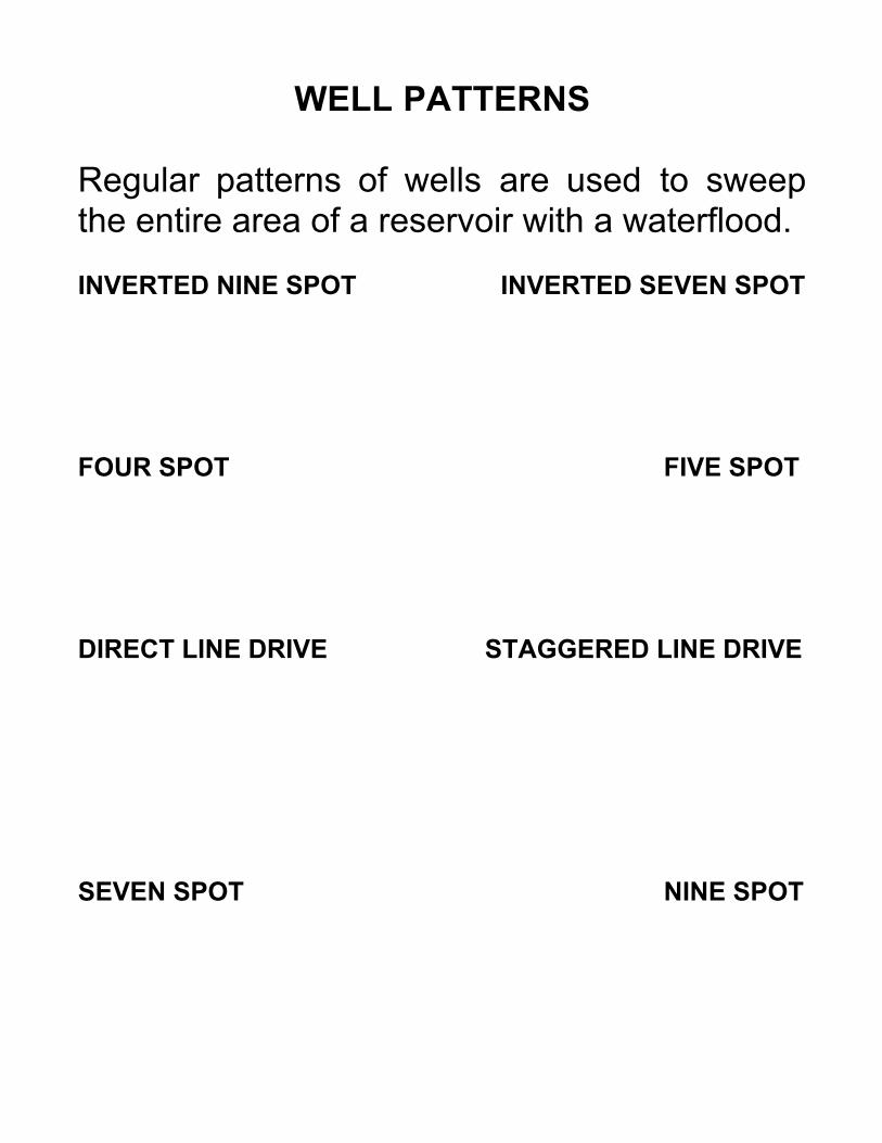
WELL PATTERNS
Regular patterns of wells are used to sweepthe entire area of a reservoir with a waterflood.
INVERTED NINE SPOT INVERTED SEVEN SPOT
FOUR SPOT FIVE SPOT
DIRECT LINE DRIVE STAGGERED LINE DRIVE
SEVEN SPOT NINE SPOT
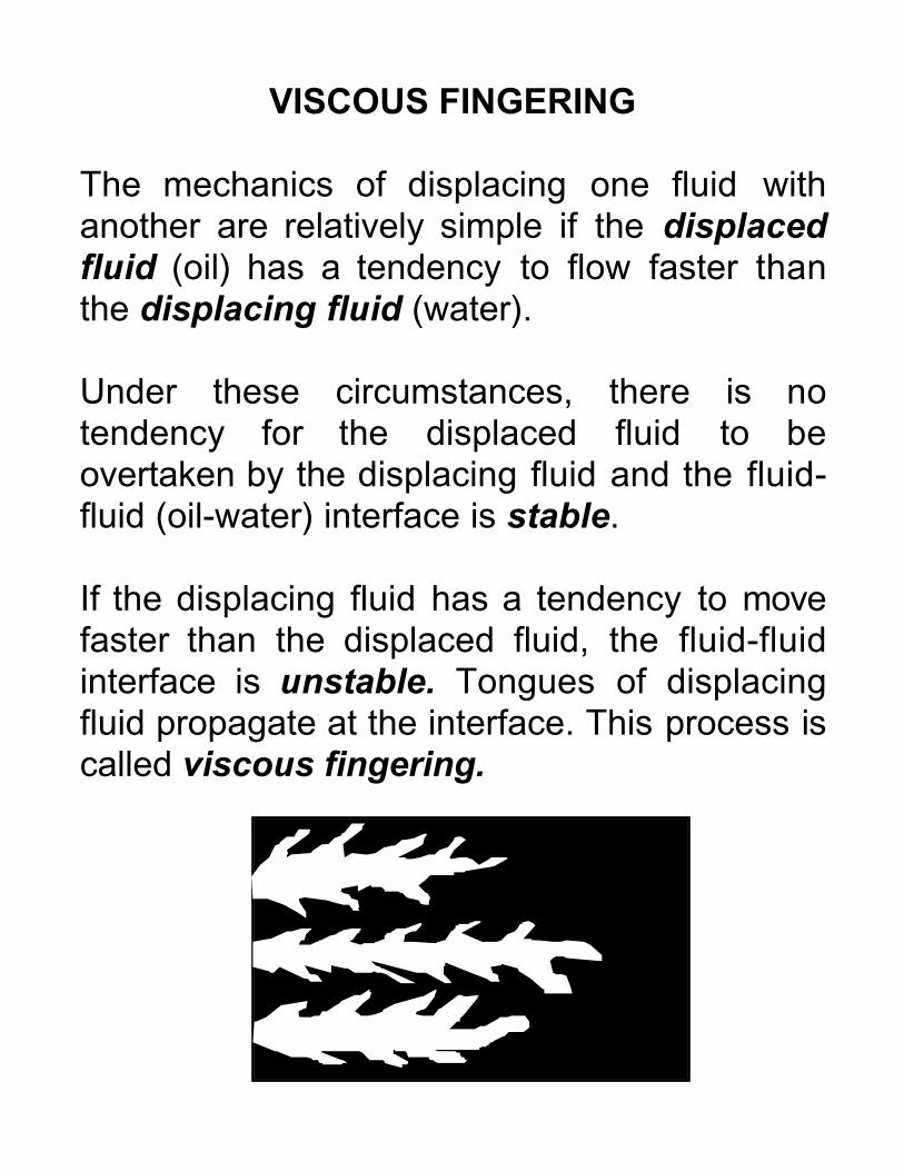
VISCOUS FINGERING
The mechanics of displacing one fluid withanother are relatively simple if the displacedfluid (oil) has a tendency to flow faster thanthe displacing fluid (water).
Under these circumstances, there is notendency for the displaced fluid to beovertaken by the displacing fluid and the fluid-fluid (oil-water) interface is stable.
If the displacing fluid has a tendency to movefaster than the displaced fluid, the fluid-fluidinterface is unstable. Tongues of displacingfluid propagate at the interface. This process iscalled viscous fingering.
MOBILITY

MOBILITY
The mechanics of displacement of one fluidwith another are controlled by differences inthe ratio of effective permeability and viscosity(k / µ).
The specific discharge (flow per unit crosssectional area) for each fluid phase dependson k / µ . This is called the fluid mobility (λ):
λλλλw = kw /µµµµw
λλλλo = ko /µµµµo
Mobility controls the relative ease with whichfluids can flow through a porous medium.
Because the relative permeabilities to oil, kro,and water, krw, depend on the fluid saturations(So = 1 - Sw and Sw = 1 - So), mobility also is astrong function of saturation.

MOBILITY RATIO
The mobility ratio is expressed as:
M = λλλλw / λλλλo
In ideal displacement, there is a sharptransition from residual oil saturation (Soi) tomaximum oil saturation (1 - Swi) at the oil-waterinterface.
Ahead of the interface, oil alone is flowing atthe end-point mobility λo
’ = ko’/µo. Behind the
interface, water alone is flowing at the end-point mobility λw
’ = kw’/µw.
Ideal displacement is the most favourable conditionfor production but only occurs if the end-pointmobility ratio is less than or equal to unity.
M’ = λλλλw’ / λλλλo
’

IDEAL DISPLACEMENT
If the mobility ratio is less than or equal to one,oil can flow at a rate greater than or equal tothat of water and is pushed ahead by the waterbank in a piston-like fashion.
The moveable oil volume (MOV) is given by:
MOV = (1 - Soi - Swi).PV
where PV is the pore volume. For a waterflood,the volume of oil recovered is exactly equal tothe volume of water injected.
Swi
1 - Soi
NON-IDEAL DISPLACEMENT (1)
Under most circumstances, water is found to bemore mobile than oil. As a result, tongues of waterbypass the oil leading to much less favourablesaturation profiles.
Some distance ahead of the water front, oil aloneflows at the end-point mobility λo
’ = ko’/µo.
At some point nearer the water front there is a sharpchange in water saturation called the shock front.
Behind the shock front there is a transition zonewhere both water and oil flow.
At the end of the transition zone, water alone isflowing at the end-point mobility λw
’ = kw’/µw.
When the shock front reaches the production wellthere is a sharp increase in watercut. This event iscalled breakthrough.

NON-IDEAL DISPLACEMENT (2)
In contrast to the ideal displacement case, atbreakthrough, only a fraction of the MOV hasbeen recovered.
Addition water injection is required to recoverthe moveable oil. Several (5 or 6) MOV’s ofwater may be needed to displace a singleMOV of oil.
The diagram shows two saturation profiles withthe shock front to the right. At breakthrough,the shaded area represents moveable oil thatremains between the injector and producer.
1 - Soi
Swi
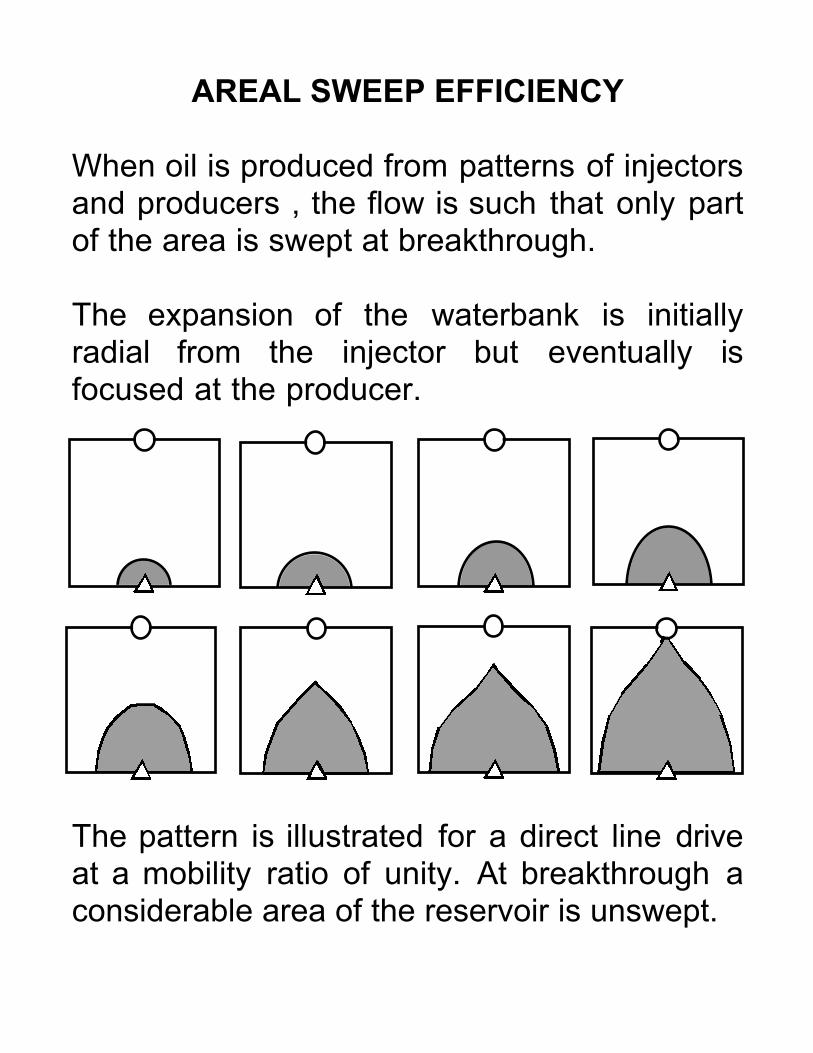
AREAL SWEEP EFFICIENCY
When oil is produced from patterns of injectorsand producers , the flow is such that only partof the area is swept at breakthrough.
The expansion of the waterbank is initiallyradial from the injector but eventually isfocused at the producer.
The pattern is illustrated for a direct line driveat a mobility ratio of unity. At breakthrough aconsiderable area of the reservoir is unswept.

MOBILITY RATIO AND SWEEP EFFICIENCY
Mobility ratio has a strong influence on arealsweep efficiency at breakthrough. For five-spotpatterns, areal sweep efficiency (ASE) atbreakthrough is over 95% for mobility ratiosless than 0.2. At M = 1.0, ASE = 67% and at M=10, ASE = 50%.
Low M
High M

ENHANCED OIL RECOVERY
The objective of EOR is to economicallyincrease displacement efficiency. The keyfactor is the mobility ratio, M:
M = λλλλw / λλλλo = [ krw(Sw) / µµµµw ] / [ kro(So) / µµµµo ]
Mobility ratio is a function of viscosity andrelative permeability, which in turn depends onsaturation.
EOR involves mobility control of various kindsthat can:
• change oil and water viscosities• change interfacial tensions• change oil and water saturations
There are four principal groups of EORtechnologies available:
• thermal EOR• miscible EOR• chemical EOR• microbial EOR
THERMAL EOR
The principle of thermal EOR is that heatincreases the mobility of oil by reducing theviscosity.
M = λw / λλλλo = [ krw(Sw) / µw ] / [ kro(So) / µµµµo ]
Oil mobility is increased relative to that of waterand the mobility ratio is reduced allowing morefavourable displacement.
Four thermal recovery methods have beeninvestigated:
• cyclic steam injection• steamflood• fireflood• microwave heating
Thermal methods are generally used in heavyoils rich in high molecular weight aromaticsand asphaltenes. The principal difficulty inextracting such oils is the very high viscosity.

CYCLIC STEAM INJECTION
Cyclic steam injection or huff and puff orsteam soak involves alternating injection ofhigh quality steam and production of oil andcondensed steam from the same well.
Well are injected with slugs of steam at veryhigh rates (millions of kilograms) for a shortperiod of time (typically 10 days).
The wells are then allowed to "soak" for afurther period of days (5 to 10) and then oil isproduced for 100 to 200 days (until theproduction rate is unacceptable).
The process is then repeated. When thewatercut becomes too high or the reservoirpressure too low for another production cycle,pools are often converted to a full steamflood.
Cyclic steam injection is the most successfulrecovery method to date for Canadian heavyoil reserves.

STEAMFLOOD
Steamflooding, also known as steam drive, involvescontinuous injection of steam to create a steam bank in thereservoir.
A pattern of injectors and producers are used in the same wayas a conventional waterflood.
Steamflood uses much more steam than cyclic injection andthe heat balance or energy balance is critical. If crude oil isburned to generate the steam, in theory 1 m3 of crude oilgenerates 12 m3 of steam. In practice, the thermal efficiency iscloser to 3:1.
Steam costs are very high and can amount to up to 50% of thevalue of the produced oil.
Steamflooding has three actions that improve the mobility ratioin the reservoir:
• heat reduces oil viscosity• thermal expansion of oil helps to free it from the
reservoir matrix.• light hydrocarbon fractions are vaporized at the heat
front and move ahead of the steam bank acting as a"natural miscible flood".
The longest running and most successful steamflood wasconducted in the Peace River oil sands in northern Alberta.

FIREFLOOD
Fireflooding or in-situ combustion provides thermal energy toreduce viscosity by burning crude oil in the reservoir. Themethod requires a relatively high permeability reservoir.
A heater or igniter is lowered down the well to initiate thefireflood. Oxygen or air is injected continuously to maintaincombustion and move the front forward. Water may also beinjected to provide additional steam (wet combustion).
Fireflooding has three actions in the reservoir:
• heat reduces oil viscosity• steam is generated in-situ to provide a component of
steam drive• combustion gases and injected gases provide a
component of gas drive.
In forward fireflood, oil burns, water is turned to steam in thecombustion zone. The lighter hydrocarbon fraction is vaporizedand coke is left in the reservoir after combustion.
If the reservoir is thin, unconsolidated and pressure is low,conventional waterflooding is ineffective and produces highsandcuts. Steamflooding is also ineffective in thin reservoirsbecause of high heat losses. In these circumstances, firefloodtends to be a last resort EOR method for heavy, viscouscrudes.

REVERSE COMBUSTION
Reverse combustion is a good idea that has yet to prove itself.
Instead of igniting the oil in the injector, the producer is ignitedand the combustion front moves out radially towards theoxygen supply (the injector). The displaced fluids movetowards the producer through hot sand so the oil is effectivelyupgraded in situ.
If reverse combustion could be developed successfully it couldrevolutionize the production of heavy, viscous crude oils inwestern Canada.
One major problem is spontaneous ignition of the oil near theinjector. This cuts off oxygen to the combustion front and thesystem reverts to forward combustion.
MICROWAVE HEATING
Another novel idea is the use of microwaves as a source ofheat. EM waves are generated with downhole equipment toheat the oil and reduce viscosity.
The technique is experimental and penetration distances arecurrently too short for effective economic production.

MISCIBLE EOR
Miscible flooding works on the principle that some fluids aremiscible with crude oil (methane, ethane, CO2 etc) and can beused to displace oil with no capillary resistance.
First contact miscible means that the injected fluids mix withreservoir fluids in all proportions as a single fluid phase. CO2 isnot strictly miscible. It has a vapour pressure very close to thewet gases and is soluble in oil at high pressures. CO2 takestime to mix (dynamically miscible).
When oil is mixed with a miscible fluid, there are no interfacialtensions or capillary forces and no interface exists.
The effect of adding a miscible fluid to the reservoir is to "swell"the oil and increase So and hence kro.
An additional benefit of miscible hydrocarbon gases and CO2 isthat they dissolve in oil to lower its viscosity, µo.
M = λw / λλλλo = [ krw(Sw) / µw ] / [ kro(So) / µµµµo ]
These two factors combine in miscible flooding to improve themobility ratio by increasing the mobility of the oil phase.
To date, miscible flooding is the only economically proventertiary recovery method applied to "normal oils" in Canada.
HYDROCARBON SOLVENT FLOODS
Several hydrocarbon fluids are used in miscible floods:• lean gas injection or vaporizing gas drive - C2 to C6
injected relatively high pressure. The light gas stripsintermediate molecular weight hydrocarbons and formsa miscible back.
• Enriched gas injection or condensing gas drive - theinjected gas condenses intermediates to form themiscible back.
• LPG slug (propane and butane) injection miscible slugdriven by either gas and/or water.
Miscible hydrocarbon flooding is not without problems:• Miscible banks are unstable. Solvents are less dense
and less viscous than oil and are subject to channelingand upward migration due to gravity effects (work well inpinnacle reefs).
• Solvent banks tend to breakdown and become lesseffective due to inhomogeneity in the reservoir.
Golden Spike is an example of a successful miscible flood. Thebrief history of the pool is:• 1949 - discovery, no gas cap, no bottom water.• 1953 - gas injection for pressure maintenance created
secondary gas cap• 1964 - injected 7% HCPV LPG slug + gas and water• 1972 - asymmetric GOC up to 40 m difference across pool• 1973 - detailed geology shows low perm zones break up the
LPG slug• 4.8 million m3 solvent recovered 1.6 million m3 oil 67% OOIP

CYCLIC CARBON DIOXIDE INJECTION
This miscible technique is analogous to cyclic steam injection.The "soak" period is advantageous because CO2 is not firstcontact miscible with oil (at normal reservoir pressures) and ittakes time for the gas to swell the oil and reduce viscosity:
• The well is injected with CO2 for a period of 20 to 100hours.
• A soak period of 5 to 20 days is allowed for the CO2 toact.
• A production period of several weeks from the samewell follows when evolution of CO2 may provideadditional solution gas drive energy.
There are some disadvantages:
• Cyclic carbon dioxide stimulation performance drops ofrapidly with number of cycles.
• If natural sources of CO2 are not available, it isexpensive to generate.
• CO2 is corrosive which adds capital costs to recoveryoperations.
• It is necessary to separate produced CO2 fromhydrocarbon gases.
Typically 900 to 2200 m3 of CO2 are required to produce 1 m3
of additional oil. This added cost can be a very significantfraction of the value of the oil (up to 70%).
CARBON DIOXIDE FLOODING
In CO2 flooding a conventional pattern ofinjectors and producers is used.
Very large volumes of CO2 are required(injection volumes are 15% HCPV or greater).
The most efficient use of CO2 is achievedwhen it is injected in alternation with water.CO2 injected alone is very mobile and tends tobypass the oil rather than dissolving in it.
This problem arises especially at lowerpressures when the dynamic miscibilitycharacteristics require the greatest amount ofcontact time for solution. At low pressures,miscibility is lost completely. There is,therefore, a minimum pressure requirement formiscible CO2 flooding.
The CO2 strips light molecules from oil andforms a miscible bank composed of CO2 andenriched light gas.

NITROGEN FLOODING
In certain circumstances, nitrogen can be asubstitute for carbon dioxide in miscible floods.
The N2 is miscible with oil at high pressure anddissolves to swell the oil and reduce viscosity.
The method is used in deep reservoirs sincethe miscibility pressure for nitrogen is inexcess of 3500 kPa.
Light oils with low Bo and low methane are thebest candidates to accept nitrogen. The N2
vaporizes light hydrocarbons and forms anenriched miscible bank as the interfacialtension is reduced to zero.
Water is commonly used as a chase fluid tomitigate problems with high gas mobility.
Nitrogen is relatively cheap, non-corrosive andcan be readily extracted from the atmosphere.

CHEMICAL EOR
Chemical EOR involves a variety of techniquesused to mainly to modify the mobility of theaqueous phase during displacement.
In polymer flooding, the objective is to reducethe mobility of the aqueous displacing phaseby increasing the viscosity:
M = λλλλw / λo = [ krw(Sw) / µµµµw ] / [ kro(So) / µo ]
The overall result is a reduced, and hencemore favourable, mobility ratio.
Surfactants have a different effect. Insurfactant or micellar floods these molecules"scrub" residual oil from pores by reducinginterfacial tensions and creating emulsions ordispersions of hydrocarbon in the aqueousphase. The action is to release oil by reducing,Soi, and hence increase the moveable oilvolume (MOV).

POLYMER FLOODING
In polymer flooding, the water is "thickened" by the addition ofwater soluble polymers.
Some of the polymers that have been tried are:
• PAC - synthetic polyacrylates (limited use).• PAM - synthetic polyacrylamides (popular).• Celluloses - starches from wastes (susceptible to attack
by enzymes).• XG - Xanthan Gum - a natural carbohydrate (popular).
The polymer flood process is:
• Injection of polymer slug• Injection of freshwater "pad" to protect the slug from
brine / formation water• Injection of brine / formation water chase fluid
The technique is most suitable for high permeability sandstonereservoirs (since polymer flooding reduces water mobility)where high watercuts have developed in the late stages ofsecondary waterflooding. In such fields, disposal of producedbrines can present an insurmountable economic andenvironmental problem.
Polymer flooding is being adopted at an earlier stage inwaterfloods because of its capability to control breakthroughand increase areal sweep efficiency.

MICELLAR FLOODING
Natural surfactants in reservoirs create emulsions or oil-in-water dispersions with viscosities similar to the aqueous phaseused to displace oil.
These "solubilizers" of hydrocarbon are polar surfactantmolecules (like detergents) called micelles. One end of themolecule is hydrophilic and attracts water, the other end ishydrophobic and attracts hydrocarbons. The overall effect is todrag residual oil into an emulsion or dispersion with theaqueous fluid.
Surfactants can also modify the balance of adhesive andcohesive forces in reservoirs and hence change the wettabilityfrom water wet to oil wet or vice versa.
Both alkaline flooding and microbial recovery methods involvethe creation of in-situ surfactants.
A micellar slug injected into a reservoir after waterflooding actsas an underground detergent or "scrubber" mobilizing residualoil by reducing the residual oil saturation. In effect, themoveable oil volume (MOV) is increased.
Micellar slugs are usually chased by polymer floods to controlmobility and reduce the tendency for channelling of waterbecause of adverse mobility ratios. The main saving is areduction in the volume of water that must be produced withthe oil emulsion or dispersion.

ALKALINE FLOODING
Alkaline or caustic flooding involves injectionof NaOH or KOH into the reservoir. Thesechemicals react with organic acids in-situ toproduce soap-like surfactants. This process isnot well understood in any quantitative way.
The technique has yet to establish itself andonly a limited number of field trials have beenundertaken with limited success. BecauseNaOH and KOH are cheap and readilyavailable, caustic flooding is the leastexpensive EOR process.
Some recent successes suggest that themethod may have considerable potentialbecause of its significant cost advantage.
In common with micellar floods, alkaline floodsare chased with a polymer pad for mobilitycontrol. For this reason only highly permeablereservoirs are candidates for the technique.

MICROBIAL EOR
Microbial methods are new and experimental areasof research.
The principle is that micro-organisms together with asource of nutrients are injected into reservoirs wherethey produce H2, CO2 and surfactants that help tomobilize oil.
Micro-organisms under consideration for use inmicrobial EOR include: fungi, algae, protozoa,viruses, aerobic and anaerobic bacteria.
A variety of natural populations of microbes exist inoil reservoirs where some use the oil as a substrate(eat oil). Among other things, micro-organisms areresponsible for:
• bacterial formation plugging• H2S generation (bacterial souring)• CO2 generation
Bacterial plugging can be used to advantage toforce displacing fluids through unswept areas.

CYCLIC MICROBIAL RECOVERY
Cyclic microbial recovery is an experimentalsingle-well technique similar to cyclic steamand cyclic CO2 simulation.
There is a short (hours) injection period whenmicro-organisms and nutrients (molasses,oxygen, etc.) are injected.
Next the wells are shut-in for an incubationperiods when CO2 and surfactants areproduced as metabolic products. This periodmay be days or weeks.
Finally, the production phase begins andextents over a period of weeks or months.When production declines, another phase ofinjection is started.
Temperature seems to be an important factorin microbial recovery and the choice of micro-organism is critical. Organisms may prove tobe specific to each individual reservoir.

MICROBIAL FLOODING
In microbial flooding a conventional pattern ofinjectors and producers is employed.
A preflush by water normally precedes themicrobial flood, which is primarily aimed atrecovering residual oil.
The bank of micro-organisms and nutrients arefollowed by water as a chase fluid to sweepthrough the reservoir.
Again the action expected of the microbes is tooxidize the oil to fatty acids (surfactants) andto generate miscible gases that contact theresidual oil to release it. The produced CO2
and biomass act to displace the oil.
A major obstacle to microbial methods is theavailability of micro-organisms that are viableunder extreme conditions of pH, pressure andtemperature.