Pressurised W ater Reactor Bottom Mounted Instrumentation ...tools were developed including ones for...
14
©2018 Westinghouse Electric Company LLC All Rights Reserved Pressurised Water Reactor Bottom Mounted Instrumentation (BMI) Repair and Inspection at Gravelines 1 Christophe Paillarès, Arnaud Jeanblanc, Martin Bolander and Karl Quirk Westinghouse Electric Company and WesDyne 86 rue de Paris 91400 ORSAY FRANCE [email protected] Abstract In December 2011, an indication was detected in a Bottom Mounted Instrumentation (BMI) penetration in the reactor vessel (RV) at EDF Gravelines Unit 1 in France [1] . WesDyne & Westinghouse were awarded a contract in March 2013 to develop, qualify and implement a first of a kind inspection & repair of the BMI. This repair involved removing the BMI and installing a plug from the inside of the reactor vessel [2] . WesDyne & Westinghouse assembled a team with expertise in reactor vessel design, welding, machining, non-destructive testing, 3D scanning and sealing. The repair took place over a 50 day period and was completed at the end of October 2016. The removal of the BMI, the machining and welding activities for installing the permanent plug, as well as volumetric and surface examinations, were performed remotely from the refueling floor using a 20m deep coffer dam, inserted into the flooded reactor cavity. The team addressed multiple technical challenges such as design, welding and remotely operated tooling, in a very constrained environment. Twenty different tools were developed including ones for automated Penetrant Testing (PT), Ultrasonic Testing (UT) and dimensional measurements. 0. Introduction Because this was a first of a kind repair, it involved the mobilization of a strong engineering team over a three year period. This project was a great challenge in terms of safety, nuclear safety, technical requirements, project management, interfacing an international team and on site implementation. The team was composed of various competencies in different technical areas; for the design of the repair process, the tooling design for each part of the process, the performance justifications for each application (including NDE), and qualification of each application. After successful qualification of the processes including; welding, machining, and non-destructive testing, the complete repair and inspection operation, following a flowchart with more than one hundred items and activities, was performed under representative site conditions at the Westinghouse Vasteras facility (Sweden). This repair scenario and demonstration was successfully completed three times: 1. For Westinghouse and WesDyne internal purposes as a dry run, 2. For EDF as qualification of the operation. 3. Under EDF supervision as qualification of the operation for the French Safety Authorities. The site intervention was performed during September and October 2016. 03/2013 12/2015 10/2016 More info about this article: http://www.ndt.net/?id=22681
Transcript of Pressurised W ater Reactor Bottom Mounted Instrumentation ...tools were developed including ones for...
©2018 Westinghouse Electric Company LLC All Rights Reserved
Pressurised Water Reactor Bottom Mounted Instrumentation (BMI)
Repair and Inspection at Gravelines 1
Christophe Paillarès, Arnaud Jeanblanc, Martin Bolander and Karl Quirk
Westinghouse Electric Company and WesDyne
86 rue de Paris 91400 ORSAY FRANCE
Abstract In December 2011, an indication was detected in a Bottom Mounted Instrumentation (BMI)
penetration in the reactor vessel (RV) at EDF Gravelines Unit 1 in France[1]
. WesDyne &
Westinghouse were awarded a contract in March 2013 to develop, qualify and implement a
first of a kind inspection & repair of the BMI. This repair involved removing the BMI and
installing a plug from the inside of the reactor vessel[2]
. WesDyne & Westinghouse assembled
a team with expertise in reactor vessel design, welding, machining, non-destructive testing,
3D scanning and sealing. The repair took place over a 50 day period and was completed at
the end of October 2016. The removal of the BMI, the machining and welding activities for
installing the permanent plug, as well as volumetric and surface examinations, were
performed remotely from the refueling floor using a 20m deep coffer dam, inserted into the
flooded reactor cavity. The team addressed multiple technical challenges such as design,
welding and remotely operated tooling, in a very constrained environment. Twenty different
tools were developed including ones for automated Penetrant Testing (PT), Ultrasonic
Testing (UT) and dimensional measurements.
0. Introduction Because this was a first of a kind repair, it involved the mobilization of a strong engineering
team over a three year period. This project was a great challenge in terms of safety, nuclear
safety, technical requirements, project management, interfacing an international team and on
site implementation. The team was composed of various competencies in different technical
areas; for the design of the repair process, the tooling design for each part of the process, the
performance justifications for each application (including NDE), and qualification of each
application. After successful qualification of the processes including; welding, machining,
and non-destructive testing, the complete repair and inspection operation, following a
flowchart with more than one hundred items and activities, was performed under
representative site conditions at the Westinghouse Vasteras facility (Sweden).
This repair scenario and demonstration was successfully completed three times:
1. For Westinghouse and WesDyne internal purposes as a dry run,
2. For EDF as qualification of the operation.
3. Under EDF supervision as qualification of the operation for the French Safety
Authorities.
The site intervention was performed during September and October 2016.
03/2013 12/2015 10/2016
Mor
e in
fo a
bout
this
art
icle
: ht
tp://
ww
w.n
dt.n
et/?
id=
2268
1
©2017 Westinghouse Electric Company LLC All Rights Reserved
2
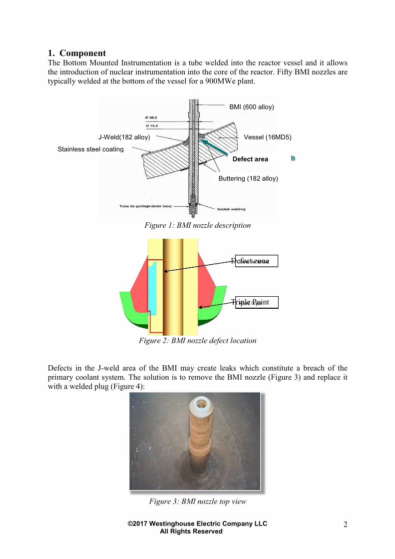
1. Component The Bottom Mounted Instrumentation is a tube welded into the reactor vessel and it allows
the introduction of nuclear instrumentation into the core of the reactor. Fifty BMI nozzles are
typically welded at the bottom of the vessel for a 900MWe plant.
Figure 1: BMI nozzle description
Figure 2: BMI nozzle defect location
Defects in the J-weld area of the BMI may create leaks which constitute a breach of the
primary coolant system. The solution is to remove the BMI nozzle (Figure 3) and replace it
with a welded plug (Figure 4):
Figure 3: BMI nozzle top view
Defect area
Vessel (16MD5)
Buttering (182 alloy)
Stainless steel coating
J-Weld(182 alloy)
BMI (600 alloy)
Defect zone
Triple Point
©2017 Westinghouse Electric Company LLC All Rights Reserved
3
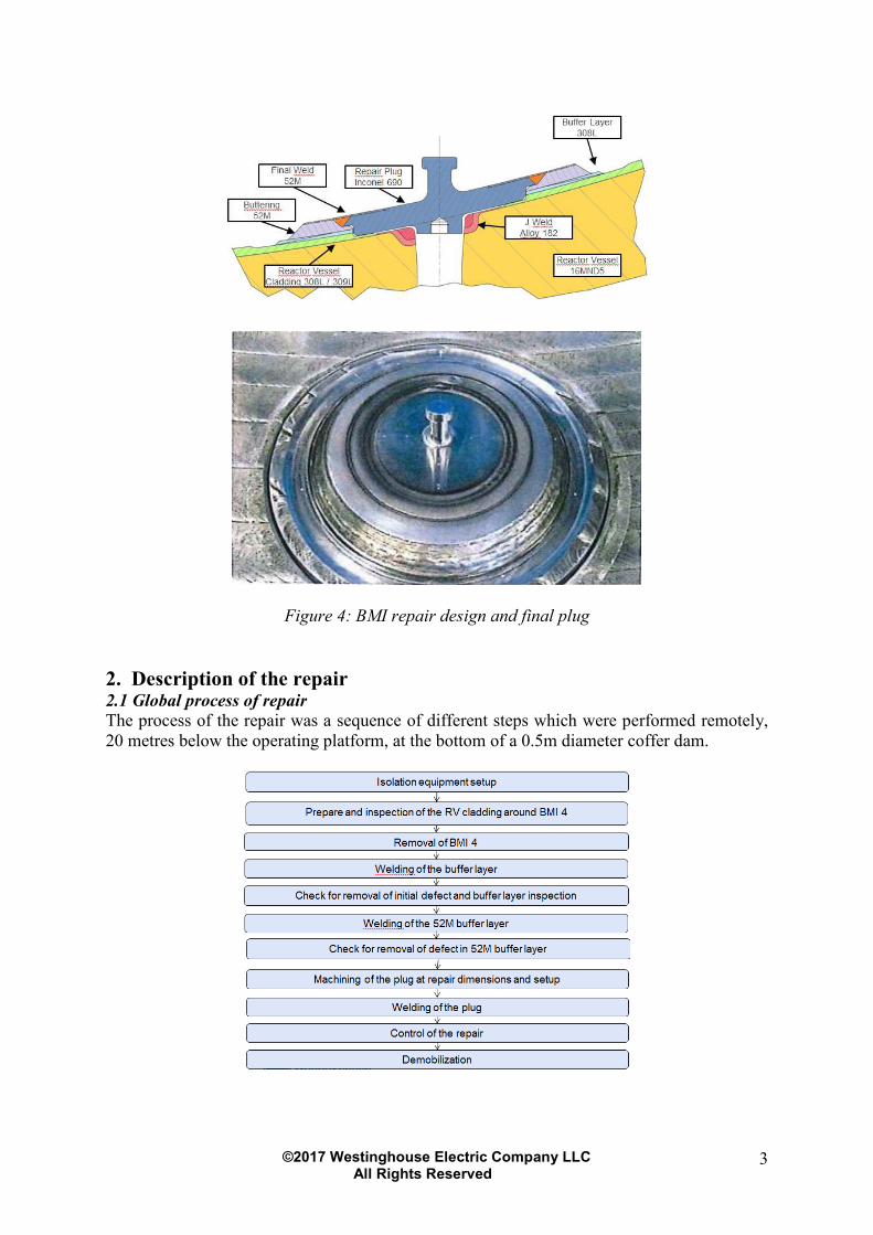
Figure 4: BMI repair design and final plug
2. Description of the repair 2.1 Global process of repair
The process of the repair was a sequence of different steps which were performed remotely,
20 metres below the operating platform, at the bottom of a 0.5m diameter coffer dam.
©2017 Westinghouse Electric Company LLC All Rights Reserved
4
To ensure the reactor vessel (RV) integrity after removing the BMI by permanent plugging,
20 different remote and automated tools were developed and qualified including:
• PT tooling
• UT tooling
• Dimensional
Scanning
• Welding Head
• Precision Milling
• EDM tools
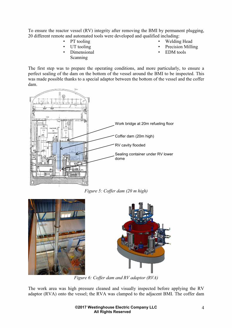
The first step was to prepare the operating conditions, and more particularly, to ensure a
perfect sealing of the dam on the bottom of the vessel around the BMI to be inspected. This
was made possible thanks to a special adaptor between the bottom of the vessel and the coffer
dam.
Figure 5: Coffer dam (20 m high)
Figure 6: Coffer dam and RV adaptor (RVA)
The work area was high pressure cleaned and visually inspected before applying the RV
adaptor (RVA) onto the vessel; the RVA was clamped to the adjacent BMI. The coffer dam
Work bridge at 20m refueling floor
Coffer dam (20m high)
RV cavity flooded
Sealing container under RV lower dome
©2017 Westinghouse Electric Company LLC All Rights Reserved
5
was then fixed onto the RVA and the water drained out. The tools were lowered down
through the coffer dam to the BMI area. The RVA was also designed to provide a reference
point for the tools when they were operating on the BMI.
2.2 NDE prior the cutting out of the BMI
Four remote controlled inspections were needed to check if the BMI tube could be extracted.
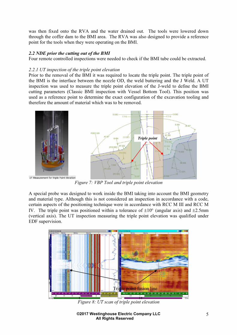
2.2.1 UT inspection of the triple point elevation
Prior to the removal of the BMI it was required to locate the triple point. The triple point of
the BMI is the interface between the nozzle OD, the weld buttering and the J Weld. A UT
inspection was used to measure the triple point elevation of the J-weld to define the BMI
cutting parameters (Classic BMI inspection with Vessel Bottom Tool). This position was
used as a reference point to determine the exact configuration of the excavation tooling and
therefore the amount of material which was to be removed.
Figure 7: VBP Tool and triple point elevation
A special probe was designed to work inside the BMI taking into account the BMI geometry
and material type. Although this is not considered an inspection in accordance with a code,
certain aspects of the positioning technique were in accordance with RCC M III and RCC M
IV. The triple point was positioned within a tolerance of ±10° (angular axis) and ±2.5mm
(vertical axis). The UT inspection measuring the triple point elevation was qualified under
EDF supervision.
Figure 8: UT scan of triple point elevation
Triple point
Triple point fusion line
©2017 Westinghouse Electric Company LLC All Rights Reserved
6
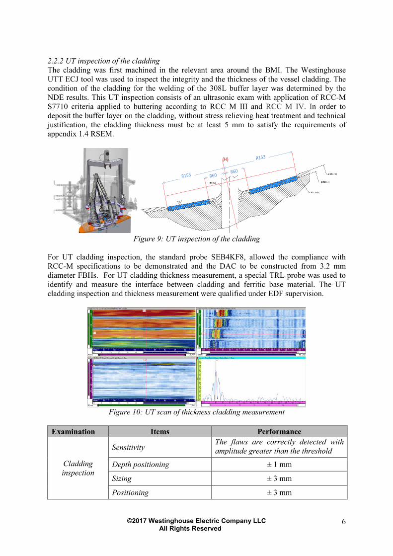
2.2.2 UT inspection of the cladding
The cladding was first machined in the relevant area around the BMI. The Westinghouse
UTT ECJ tool was used to inspect the integrity and the thickness of the vessel cladding. The
condition of the cladding for the welding of the 308L buffer layer was determined by the
NDE results. This UT inspection consists of an ultrasonic exam with application of RCC-M
S7710 criteria applied to buttering according to RCC M III and RCC M IV. In order to
deposit the buffer layer on the cladding, without stress relieving heat treatment and technical
justification, the cladding thickness must be at least 5 mm to satisfy the requirements of
appendix 1.4 RSEM.
(H)
Figure 9: UT inspection of the cladding
For UT cladding inspection, the standard probe SEB4KF8, allowed the compliance with
RCC-M specifications to be demonstrated and the DAC to be constructed from 3.2 mm
diameter FBHs. For UT cladding thickness measurement, a special TRL probe was used to
identify and measure the interface between cladding and ferritic base material. The UT
cladding inspection and thickness measurement were qualified under EDF supervision.
Figure 10: UT scan of thickness cladding measurement
Examination Items Performance
Cladding
inspection
Sensitivity The flaws are correctly detected with
amplitude greater than the threshold
Depth positioning ± 1 mm
Sizing ± 3 mm
Positioning ± 3 mm

©2017 Westinghouse Electric Company LLC All Rights Reserved
7
Cladding
thickness Thickness measurement ± 1 mm
2.2.3 ET J-Weld interface location
An eddy current (ET) inspection was performed to define the weld boundary on the vessel
and then the future buttering area on the vessel bottom with the UTT ECJ tool on the surface
of the cladding. During the replacement process a “buffer layer” was welded to the existing
RV cladding. When the preparation machining for the “buffer layer” was complete, the
positioning of the J-Weld boundary was performed.
Figure 11: ET J-weld Boundary
The goal of the inspection was to identify and quantify the interface between the Inconel 182
Weld and Stainless Steel Cladding. An ET probe designed for material recognition was used.
The difference in the material characteristic/electromagnetic changes in conductivity was
used to determine the interface between the two materials. The radius of the J weld interface
was positioned within a tolerance of ± 2,5mm.
Figure 12: ET J-weld interface between cladding and J weld
The ET inspection was qualified under EDF supervision.
2.2.4 PT Examination
J Weld Boundary
©2017 Westinghouse Electric Company LLC All Rights Reserved
8
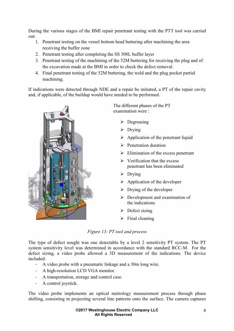
During the various stages of the BMI repair penetrant testing with the PTT tool was carried
out:
1. Penetrant testing on the vessel bottom head buttering after machining the area
receiving the buffer zone
2. Penetrant testing after completing the SS 308L buffer layer
3. Penetrant testing of the machining of the 52M buttering for receiving the plug and of
the excavation made at the BMI in order to check the defect removal.
4. Final penetrant testing of the 52M buttering, the weld and the plug pocket partial
machining.
If indications were detected through NDE and a repair be initiated, a PT of the repair cavity
and, if applicable, of the buildup would have needed to be performed.
The different phases of the PT
examination were :
Degreasing
Drying
Application of the penetrant liquid
Penetration duration
Elimination of the excess penetrant
Verification that the excess
penetrant has been eliminated
Drying
Application of the developer
Drying of the developer
Development and examination of
the indications
Defect sizing
Final cleaning
Figure 13: PT tool and process
The type of defect sought was one detectable by a level 2 sensitivity PT system. The PT
system sensitivity level was determined in accordance with the standard RCC-M. For the
defect sizing, a video probe allowed a 3D measurement of the indications. The device
included:
- A video probe with a pneumatic linkage and a 30m long wire.
- A high-resolution LCD VGA monitor.
- A transportation, storage and control case.
- A control joystick.
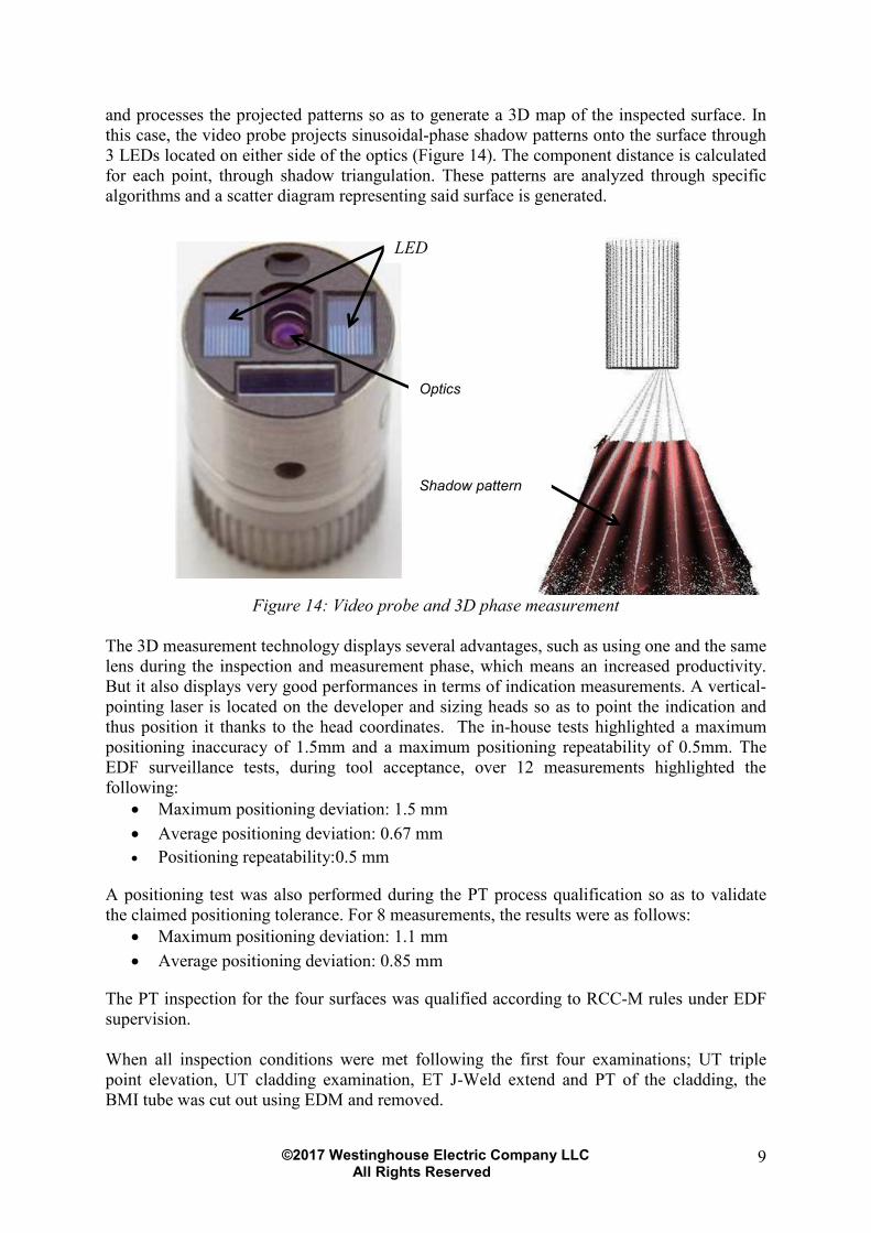
The video probe implements an optical metrology measurement process through phase
shifting, consisting in projecting several line patterns onto the surface. The camera captures
©2017 Westinghouse Electric Company LLC All Rights Reserved
9
and processes the projected patterns so as to generate a 3D map of the inspected surface. In
this case, the video probe projects sinusoidal-phase shadow patterns onto the surface through
3 LEDs located on either side of the optics (Figure 14). The component distance is calculated
for each point, through shadow triangulation. These patterns are analyzed through specific
algorithms and a scatter diagram representing said surface is generated.
Figure 14: Video probe and 3D phase measurement
The 3D measurement technology displays several advantages, such as using one and the same
lens during the inspection and measurement phase, which means an increased productivity.
But it also displays very good performances in terms of indication measurements. A vertical-
pointing laser is located on the developer and sizing heads so as to point the indication and
thus position it thanks to the head coordinates. The in-house tests highlighted a maximum
positioning inaccuracy of 1.5mm and a maximum positioning repeatability of 0.5mm. The
EDF surveillance tests, during tool acceptance, over 12 measurements highlighted the
following: • Maximum positioning deviation: 1.5 mm
• Average positioning deviation: 0.67 mm
• Positioning repeatability:0.5 mm
A positioning test was also performed during the PT process qualification so as to validate
the claimed positioning tolerance. For 8 measurements, the results were as follows: • Maximum positioning deviation: 1.1 mm
• Average positioning deviation: 0.85 mm
The PT inspection for the four surfaces was qualified according to RCC-M rules under EDF
supervision.
When all inspection conditions were met following the first four examinations; UT triple
point elevation, UT cladding examination, ET J-Weld extend and PT of the cladding, the
BMI tube was cut out using EDM and removed.
Optics
Shadow pattern
LED
©2017 Westinghouse Electric Company LLC All Rights Reserved
10
2.3 NDE after each step of welding
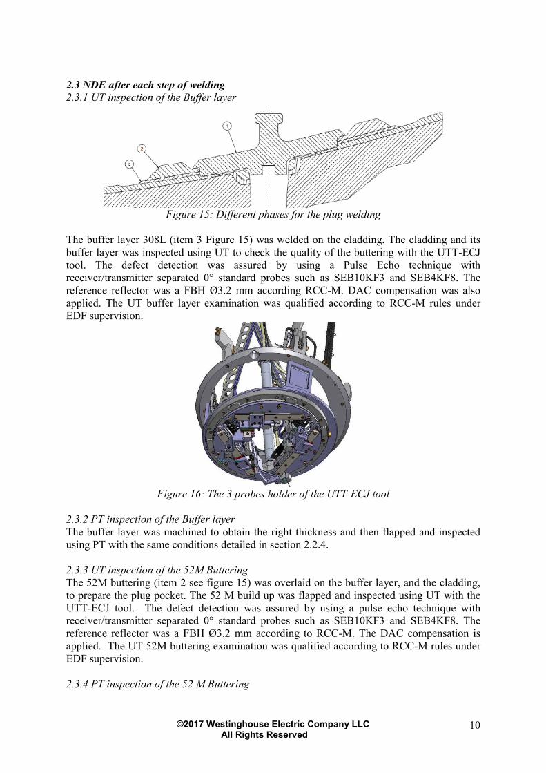
2.3.1 UT inspection of the Buffer layer
Figure 15: Different phases for the plug welding
The buffer layer 308L (item 3 Figure 15) was welded on the cladding. The cladding and its
buffer layer was inspected using UT to check the quality of the buttering with the UTT-ECJ
tool. The defect detection was assured by using a Pulse Echo technique with
receiver/transmitter separated 0° standard probes such as SEB10KF3 and SEB4KF8. The
reference reflector was a FBH Ø3.2 mm according RCC-M. DAC compensation was also
applied. The UT buffer layer examination was qualified according to RCC-M rules under
EDF supervision.
Figure 16: The 3 probes holder of the UTT-ECJ tool
2.3.2 PT inspection of the Buffer layer
The buffer layer was machined to obtain the right thickness and then flapped and inspected
using PT with the same conditions detailed in section 2.2.4.
2.3.3 UT inspection of the 52M Buttering
The 52M buttering (item 2 see figure 15) was overlaid on the buffer layer, and the cladding,
to prepare the plug pocket. The 52 M build up was flapped and inspected using UT with the
UTT-ECJ tool. The defect detection was assured by using a pulse echo technique with
receiver/transmitter separated 0° standard probes such as SEB10KF3 and SEB4KF8. The
reference reflector was a FBH Ø3.2 mm according to RCC-M. The DAC compensation is
applied. The UT 52M buttering examination was qualified according to RCC-M rules under
EDF supervision.
2.3.4 PT inspection of the 52 M Buttering

©2017 Westinghouse Electric Company LLC All Rights Reserved
11
The plug pocket was created in the buttering by EDM, milling and flapping, and then
inspected using PT with the same conditions detailed in the section 2.2.4.
2.3.5 3D scan of the plug pocket
The 3D scanning was performed to acquire a three-dimensional model of the actual geometry
during the repair process. The dimensions of the plug pocket were measured by a 3D laser
scan. The plug (item 1, Figure 15) was also checked with a 3D scan.
Figure 17: The 3D Laser Measurement of excavation
The volumetric accuracy obtained during the 3D scanning was: • ± 0,040 mm on the ball diameters (spherical references). • ± 0,040 mm for the distances between the balls.
2.3.6 UT and PT of the final weld
When the plug and the pocket were matched, the plug was welded in the pocket as shown in
figure 18:
Figure 18: Final weld
After EDM of the weld profile, UT and PT final inspections were performed on the plug
weld. The final weld was machined then flapped and inspected using PT with the conditions
detailed in section 2.2.4. The UT examination met the requirements of RCC-M section MC
2610 for the detection of defects like lack of fusion in stainless steel welds. When the RCC-
M code could not be applied directly, because of technical difficulties in austenitic welds, we
justified the criteria developed. The potential flaws were lack of fusion / bonding type,
oriented along the chamfer and between weld beads. The target defect had the following
characteristics; circumferential orientated, 2.5 mm high and 10 mm long. The technique used
dual element ultrasonic longitudinal probes at; 0° (2 transducers, 10 MHz and 4 MHz), 35°
and 50° (2 MHz). One set of three probes was used in the direction towards the plug and the
other set was facing away from the plug. DAC compensation was also applied.
©2017 Westinghouse Electric Company LLC All Rights Reserved
12
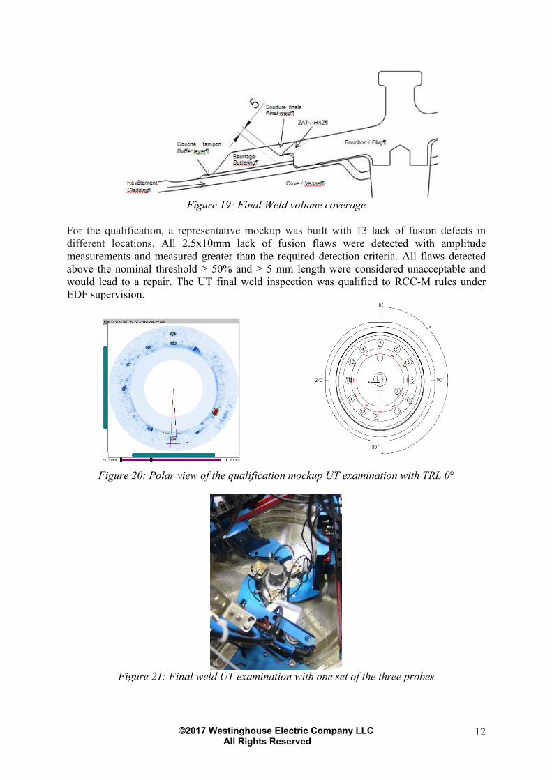
Figure 19: Final Weld volume coverage
For the qualification, a representative mockup was built with 13 lack of fusion defects in
different locations. All 2.5x10mm lack of fusion flaws were detected with amplitude
measurements and measured greater than the required detection criteria. All flaws detected
above the nominal threshold ≥ 50% and ≥ 5 mm length were considered unacceptable and
would lead to a repair. The UT final weld inspection was qualified to RCC-M rules under
EDF supervision.
Figure 20: Polar view of the qualification mockup UT examination with TRL 0°
Figure 21: Final weld UT examination with one set of the three probes
©2017 Westinghouse Electric Company LLC All Rights Reserved
13
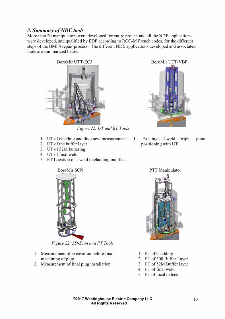
3. Summary of NDE tools More than 20 manipulators were developed for entire project and all the NDE applications
were developed, and qualified by EDF according to RCC-M French codes, for the different
steps of the BMI 4 repair process. The different NDE applications developed and associated
tools are summarized below:
BoroMir UTT-ECJ BoroMir UTT-VBP
Figure 22: UT and ET Tools
1. UT of cladding and thickness measurement
2. UT of the buffer layer
3. UT of 52M buttering
4. UT of final weld
5. ET Location of J-weld to cladding interface
1. Existing J-weld triple point
positioning with UT
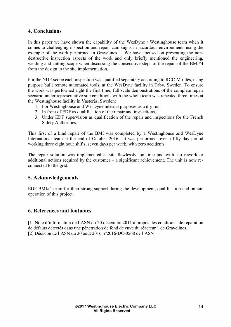
BoroMir SCN PTT Manipulator
Figure 22: 3D-Scan and PT Tools
1. Measurement of excavation before final
machining of plug
2. Measurement of final plug installation
1. PT of Cladding
2. PT of 308 Buffer Layer
3. PT of 52M Buffer layer
4. PT of final weld
5. PT of local defects
©2017 Westinghouse Electric Company LLC All Rights Reserved
14
4. Conclusions
In this paper we have shown the capability of the WesDyne / Westinghouse team when it
comes to challenging inspection and repair campaigns in hazardous environments using the
example of the work performed in Gravelines 1. We have focused on presenting the non-
destructive inspection aspects of the work and only briefly mentioned the engineering,
welding and cutting scope when discussing the consecutive steps of the repair of the BMI#4
from the design to the site implementation.
For the NDE scope each inspection was qualified separately according to RCC-M rules, using
purpose built remote automated tools, at the WesDyne facility in Täby, Sweden. To ensure
the work was performed right the first time, full scale demonstrations of the complete repair
scenario under representative site conditions with the whole team was repeated three times at
the Westinghouse facility in Västerås, Sweden:
1. For Westinghouse and WesDyne internal purposes as a dry run,
2. In front of EDF as qualification of the repair and inspections.
3. Under EDF supervision as qualification of the repair and inspections for the French
Safety Authorities.
This first of a kind repair of the BMI was completed by a Westinghouse and WesDyne
International team at the end of October 2016. It was performed over a fifty day period
working three eight hour shifts, seven days per week, with zero accidents.
The repair solution was implemented at site flawlessly, on time and with, no rework or
additional actions required by the customer – a significant achievement. The unit is now re-
connected to the grid.
5. Acknowledgements
EDF BMI#4 team for their strong support during the development, qualification and on site
operation of this project.
6. References and footnotes
[1] Note d’information de l’ASN du 20 décembre 2011 à propos des conditions de réparation
de défauts détectés dans une pénétration de fond de cuve du réacteur 1 de Gravelines.
[2] Décision de l’ASN du 30 août 2016 n°2016-DC-0568 de l’ASN