Pressure Relief Valves Series VS
28
Catalogue N°: Revision: 02 of 29.10.2001 10VSCATR02-E Pressure Relief Valves Series VS
Transcript of Pressure Relief Valves Series VS

Catalogue N°:
Revision: 02 of 29.10.2001
10VSCATR02-E
Pressure ReliefValves
Series VS

Specification N° SPR/ Accessory: Page N°:
Title: Revision:
C:\ETI\TECH\SPE\SPEWORD\SPEAGG\10\10VSGENR02-E-Mail.doc
02 – 29/10/01
10VSGENR02-E
Function, features, operation and assembly
Pressure relief valve Series VS 1of 5
1.0 Function, features, operation and assemblyThis specification concerns the function, the main features and the operation of the accessory con-cerned, as well as the admitted environmental and operating condition for the different executions.Operating conditions depend generally from the compatibility of the materials, components, sur-face finish, and, for the electric contacts and circuits, their degree of protection, with the operatingconditions of the transformer.
2.0 FunctionThe pressure relief valve opens when the pressure inside the tank increases over the set operatingvalue, following for example a failure or a short circuit, and by releasing oil reduces the pressure inthe tank. By means of the electric contact, if present, and the optical indication the pressure reliefvalve indicates that a fault has taken place.
3.0 Construction features3.1.0 Materials and components
• Flange, obturator, cover and electric contact’s casing are of cast aluminium;• Fittings are of stainless steel or nickel coated brass;• Gasket materials as specified for the different executions;• Splash diverter is made of stainless steel;• Springs are of spring steel, sandblasted and painted with epoxy powders;• External screws are of stainless steel.
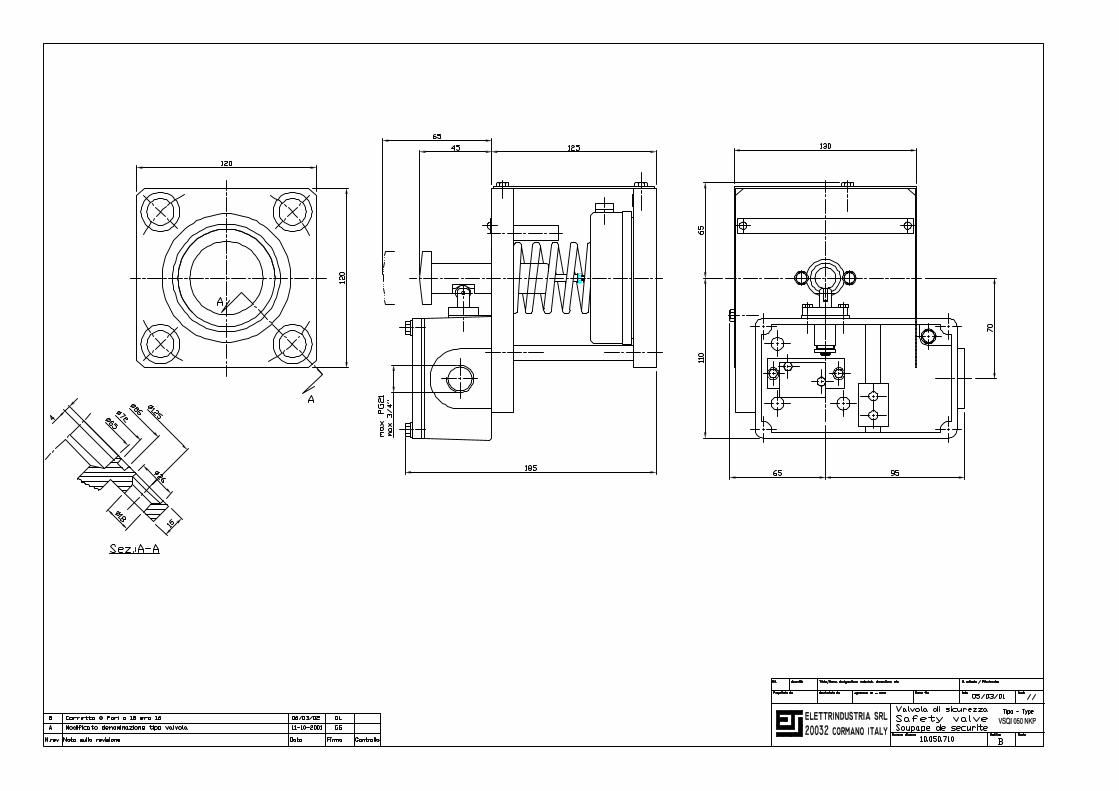
3.2.0 Reference drawingsOverall dimensions:Pressure relief valves with contact type K• Type VSQI 050 NKP - nominal diameter 50 mm N° 10.050.710• Type VS 080 NKP - nominal diameter 80 mm N° 10.080.90• Type VS 100 NKP - nominal diameter 100 mm N° 10.100.90• Type VS 150 NKP - nominal diameter 150 mm N° 10.150.90Pressure relief valves with contact type C• Type VS 080 NCP - nominal diameter 80 mm N° 10.080.10• Type VS 100 NCP- nominal diameter 100 mm N° 10.100.10• Type VS 150 NCP - nominal diameter 150 mm N° 10.150.10Pressure relief valves without contact• Type VSQI 050 N - nominal diameter 50 mm N° 10.050.705The drawings show the valves complete with splash diverter.
3.3.0 ConstructionThe pressure relief valves Series VS are spring operated safety valves, consisting of a mountingflange with the central opening closed by a spring loaded obturator; the springs are compressedbetween obturator and cover, which is assembled to the flange by columns.No part of the pressure relief valve reaches inside the transformer tank. A specially designed gas-ket assures the oil-tightness between flange and obturator when the valve is closed.

Specification N° SPR/ Accessory: Page N°:
Title: Revision:
C:\ETI\TECH\SPE\SPEWORD\SPEAGG\10\10VSGENR02-E-Mail.doc
02 – 29/10/01
10VSGENR02-E
Function, features, operation and assembly
Pressure relief valve Series VS 2of 5
3.4.0 Pressure setting and springsThe setting of the pressure relief valves Series VS is effected by choosing a different spring - forType VS 150 a double spring set – for every operating pressure value; therefore the setting of thepressure relief valve can be changed only at the factory, thus eliminating possible misuses.The springs are of the compression type, designed so as to have a limited force gain with thestroke.Specification N° SPR/10VSTARRxx indicates the tolerance of the setting and the minimum oper-ating pressure for the different pressure settings as well as the minimum pressure at which thevalve closes after operation.
3.5.0 Operation indication3.5.1.0 Optical indication
The pressure relief valves Series VS have as a standard feature an optical indication that thevalve has operated; this optical indication consists of a red pin showing about 30 mm over thetop of the valve cover when the valve has operated because of an internal overpressure. Forvalves Type VS 080, VS 100 and VS 150 the pin is spring loaded so that even in case of partialopenings of the valve due to small or short-duration overpressures the pin is nevertheless ex-pelled completely. For Type VSQI 050 the optical indication operates also the electric contact, ifpresent.
3.5.2.0 Electric contactThe operation of the pressure relief valve can be indicated also by an electric contact, which canbe of the “C” type, according to specification N° SPR/10VSSCHCRxx or of the “K” type accordingto specification N° SPR/10VSSCHKRxx.
3.6.0 Splash diverterTo avoid that during the operation of the valve hot oil is shot in all directions, thus increasing thedanger to man and machine, the valves Series VS can be fitted with a splash diverter, which di-verts the out-flowing oil in a determined direction.
3.7.0 Oil-tightness and resistance to pressureThe pressure relief valves Series VS:• are oil tight to oil at 100°C up to pressure Pt, which depends on the setting pressure;• are mechanically and electrically resistant to vacuum (10 torr);• have a mechanical resistance to pressures up to 4 bars.
3.8.0 Resistance to dynamical stressThe pressure relief valves Series VS can operate without undue operation in following conditions:• Sinus vibrations with frequency <= 120 Hz and amplitude <= 250 µ;• Dynamical conditions causing following accelerations:
◊ Max 3g in all directions, sinus vibration, amplitude <= 20 mm;◊ Shock condition with max 10 g in all directions.
3.9.0 Surface protectionFlange, obturator, cover and contact’s casing are painted internally and externally with one primercoat of epoxyd paint and externally with a finishing coat of polyurethane paint colour RAL 7031.The primer coat on the internal surfaces in contact is compatible with transformer mineral oil up totemperatures of 120°C.The painting procedure is accepted by the Italian electricity authority ENEL.

Specification N° SPR/ Accessory: Page N°:
Title: Revision:
C:\ETI\TECH\SPE\SPEWORD\SPEAGG\10\10VSGENR02-E-Mail.doc
02 – 29/10/01
10VSGENR02-E
Function, features, operation and assembly
Pressure relief valve Series VS 3of 5
The specification N° SPR/00VERRxx describes in details all the features of the painting procedurerelevant to the protection against corrosion.
4.0 Operation and installation4.1.0 Operation
Should an overpressure inside the transformer tank build up due to short circuit or else, higherthan the set operation pressure of the pressure relief valve Series VS, the obturator lifts from theflange propelled by the pressure, thus opening the discharge opening. The oil can flow out thus re-ducing the overpressure; at the same time the optical indication and if installed the electric contactshow that the valve has operated.When the overpressure has been discharged the valve shuts again automatically to complete oil-tightness.Thanks to the design of the pressure relief valves Series VS and their springs, the full opening isreached even for small overpressures in a matter of milliseconds, so as to reduce the resistance tothe oil flow.
4.2.0 Importance of the electric contactReal life tests have shown, that failures of the transformer followed by sudden pressure increases,such as for instance short circuits, induce the operation of the pressure relief valve in time spanswhich are considerably shorter than that of other safety devices, such as the Buchholz Relay. Toexploit this rapid operation for the safety of the transformer we strongly advice to fit out thepressure relief valve Series VS with electric contacts, which should be connected to the tripcircuit of the transformer.
4.3.0 InstallationThe pressure relief valve should be installed, either in horizontal or vertical position, on the trans-former tank, as near as possible to possible failure sources or in a central position to such sources.The size of the pressure relief valve should be chosen considering the available space and the oilquantity to be vented in case of failure.For a higher safety standard and to increase the rapidity of operation it can be preferable to installmore than one pressure relief valve eventually of a smaller size.
4.4.0 Choice of nominal pressureTo avoid oil leakage or undue operation of the valve, the operating pressure should be chosen sothat in normal operation the corresponding maximum operating pressure is never reached. Fur-thermore, to reduce oil loss after operation, the minimum pressure at which the valve closes afteroperation should be always higher than the oil head insisting on the valve.
5.0 CompatibilityThe installation compatibility of the pressure relief valves Series VS depend mainly on the materialused for the gaskets; therefore the executions differ because of the used gaskets.
5.1.0 Standard execution – nitrile rubber gaskets (N)Admitted operating conditions are:Environmental conditions:Ambient temperature -20°C to +50°CRelative humidity 95% to 20°C - 80% to 40°C - 50% to 50°C

Specification N° SPR/ Accessory: Page N°:
Title: Revision:
C:\ETI\TECH\SPE\SPEWORD\SPEAGG\10\10VSGENR02-E-Mail.doc
02 – 29/10/01
10VSGENR02-E
Function, features, operation and assembly
Pressure relief valve Series VS 4of 5
Insulating liquid: transformer mineral or silicon oilTemperature - 20°C to + 110°C
5.2.0 Execution Nf - nitrile rubber gaskets for low temperatures (Nf)Admitted operating conditions are:Environmental conditions:Ambient temperature -40°C to +50°CRelative humidity 95% to 20°C - 80% to 40°C - 50% to 50°CInsulating liquid: transformer mineral or silicon oilTemperature - 40°C to + 120°C
5.3.0 Execution V – fluor rubber gaskets (Viton V)Admitted operating conditions are:Environmental conditions:Ambient temperature -15°C to +50°CRelative humidity 95% to 20°C - 80% to 40°C - 50% to 50°CInsulating liquid: transformer mineral or silicon oilTemperature - 15°C to + 150°C
5.4.0 Special executionsFor other environmental and/or operating conditions to be examined individually.

Specification N° SPR/ Accessory: Page N°:
Title: Revision:
C:\ETI\TECH\SPE\SPEWORD\SPEAGG\10\10VSGENR02-E-Mail.doc
02 – 29/10/01
10VSGENR02-E
Function, features, operation and assembly
Pressure relief valve Series VS 5of 5
6.0 Identification of typesTaking for exemple type VS 080 NCP 0,5, which indicates:• pressure relief valve series VS• nominal diameter 80 mm• with nitrile rubber gaskets N• with one contact type C• with splash diverter P• with operating pressure 0,5 bars,the pressure relief valves Series VS are identified as follows:
VS 080 N C P 0,5Series identification:
VS Pressure relief valve Series VS, types VS 080, VS 100, VS 150VSC Only for pressure relief valves Series VSC, type VSC 050VSQ Only for pressure relief valves Series VSQ, type VSQ 050
Identification of nominal diameter:050 Nominal diameter 50 mm080 Nominal diameter 80 mm100 Nominal diameter 100 mm150 Nominal diameter 150 mm
Identification of gasket type:N Nitrile rubber gasketsNf Nitrile rubber gaskets for low temperaturesV Fluor rubber gaskets (Viton)
Identification of contact – see contacts specifications… Contact type …
Optional splash diverter:- Without splash diverterP With splash diverter
Operating pressure:0,5 Operating pressure 0,5 bars
7.0 Reference specifications• Setting tolerance N° SPR/10VSTARRxx• Wiring diagrams and contacts
Contacts type C N° SPR/10VSSCHCRxxContacts type K N° SPR/10VSSCHKRxx
• Painting N° SPR/00VERRxx

Specification N° SPR/ Accessory: Page N°:
Title: Revision:
C:\ETi\TECH\SPE\SPEWORD\SPEAGG\10\10VSSCHCR00-E-Mail.doc
00 – 10/10/99
10VSSCHCR00-E
Features contact type C
Pressure relief valve Series VS 1of 1
1.0 Features contact type CThe specification indicates the electrical and mechanical features as well as the admitted environ-mental conditions for the contact type C and it’s wiring.
2.0 Resetting of the contactIn standard execution the contact resets automatically when the valve closes after the overpres-sure is discharged. On request the contact can be supplied with manual reset and in this case theresetting of the contact after operation is obtained by acting on the spring that hooks the lever inthe operating position.
3.0 FeaturesThe contact type C is a mechanically operated sudden operation changeover microswitch withdouble interruption bedded in a protecting casing; it can have one or two contacts and the con-struction is usually Telemecanique.• Telemecanique – one contact type ZCK-J1• Telemecanique – two contacts type ZCK-J2• Degree of protection IP 66• Standard cable gland PG 13,5• Cable gland on request M20• Resistance to vibrations (IEC 68-2-6) 25g from 10 to 500 Hz• Resistance to shock 50g• Protection against electric shocks Class I according to IEC 536• Contact resistance ≤ 25 mOhms• Standard interruption power (1x10⁵ operations) AC 250V-3,5A - 24V-10A
DC 24V-10W - 120V-4W• Short life interruption power (100 operations) DC 120V-150W• Insulation to earth at 20°C 2.500V• Insulation of open contact at 20°C 1.500V
4.0 Table of function and operation of contactWiring
diagramN°
TerminalN°
Contact’sposition
in NEDescription of wiring diagram
13-14 Open10-131C 21-22 Closed1 changeover contact, trips with overpressure;name of wiring diagram on type label = C
14-13/23-24 Open10-291C 11-12/21-22 Closed2 changeover contacts, trip with overpressure;name of wiring diagram on type label = 2C
Two contacts having the same function may not operate simultaneously.If manual reset of the contact is present, the letter m is added to the contact’s name on the typelabel.Notes:NE = Normal operation; the pressure in the tank is lower than the setting pressure of the valve:Wiring diagram N° = Identification number of the wiring diagramTerminal N° = Identification of the terminals by numbersContact’s position in NE = State of the contact in normal operation.

Specification N° SPR/ Accessory: Page N°:
Title: Revision:
C:\ETi\TECH\SPE\SPEWORD\SPEAGG\10\10VSSCHKR00-E-Mail.doc
00 – 10/10/99
10VSSCHKR00-E
Features contact type K
Pressure relief valve Series VS 1of 2
1.0 Features contact type KThe specification indicates the electrical and mechanical features as well as the admitted environ-mental conditions for the contact type K and it’s wiring.
2.0 Resetting of the contactIn standard execution the contact must be reset manually after operation, when the valve closesafter the overpressure is discharged, by acting on the hook that holds the lever in the operatingposition. By dismantling the hook, the contact resets automatically.
3.0 FeaturesThe contact type K is a mechanically operated sudden operation changeover microswitch with oneinterruption; the microswitch is mounted inside an aluminium protecting case and the terminals areconnected to a terminal board.
3.1.0 Standard contact (ST) - Crouzet type 83 169 4 or Matsushita• Degree of protection IP 67• Lever and pushbutton Stainless steel• Contact material Nickel coated silver• Mechanical endurance of contact 1x10⁷ cyles• Temperature range -40°C - +125°C• Standard interruption power AC 250V-5A - DC 125V-1A• Short endurance interruption power DC 125V-1,5A• Insulation to earth at 20°C 2.500V• Insulation of open contact at 20°C 1.500V• Minimum and maximum current 1,0 - 10A
3.2.0 Low current contact (BC) - Crouzet type 83 169 8Contacts type BC are used only on request; features are identical to standard contact except for:• Contact material Gold alloy• Minimum and maximum current 1 to 100mA - 4 to 30V
3.3.0 Electric circuit• Degree of protection of protective casing IP 65• Material of casing Aluminium• Insulation to earth at 20°C 2.500V• Material of terminals tin coated brass

Specification N° SPR/ Accessory: Page N°:
Title: Revision:
C:\ETi\TECH\SPE\SPEWORD\SPEAGG\10\10VSSCHKR00-E-Mail.doc
00 – 10/10/99
10VSSCHKR00-E
Features contact type K
Pressure relief valve Series VS 2of 2
4.0 Table of function and operation of contactWiring
diagramN°
TerminalN°
Contact’sposition
in NEDescription of wiring diagram
1-2 Open10-131K 1-3 Closed1 changeover contact, trips with overpressure;name of wiring diagram on type label = K
1-2 / 4-5 Open10-291K 1-3 / 4-6 Closed2 changeover contacts, trip with overpressure;name of wiring diagram on type label = 2K
Two contacts having the same function may not operate simultaneously.If manual reset of the contact is present, the letter m is added to the contact’s name on the typelabel.Notes:NE = Normal operation; the pressure in the tank is lower than the setting pressure of the valve:Wiring diagram N° = Identification number of the wiring diagramTerminal N° = Identification of terminals by numbersContact’s position in NE = State of the contact in normal operation.

Specification N° SPR/ Accessory: Page N°:
Title: Revision:
C:\ETI\TECH\SPE\SPEWORD\SPEAGG\10\10VSTARR03-E-Mail.doc
03 – 24.10.01
10VSTARR03-E
Setting tolerance, operating pressure
Pressure relief valve Series VS 1of 1
1.0 Setting tolerance, operating pressureThe specification defines the terminology and indicates the setting pressure tolerance and all theother pressure values relevant for the test and operation of the pressure relief valves Series VS.The performance of the pressure relief valves depends from the test fluid and the layout of thetransformer tank. The pressure values listed below are obtained by operating the valves with com-pressed air on a test bed having a compressed air volume of 150 dm3.
2.0 Definitions2.1.0 Nominal pressure – Pn
The nominal pressure is the setting pressure of the pressure relief valve, on which the tolerancemust be applied in order to determinate the minimum and maximum operating pressure.
2.2.0 Minimum and maximum operating pressure - Pmin, PmaxMinimum and maximum operating pressure are the limits of the pressure range inside which thepressure relief valve must operate. The table indicates the %age on the nominal pressure as wellas the actual pressure.
2.3.0 Service pressure – PeThe service pressure is the maximum pressure the pressure relief valve can withstand withoutshowing oil leakage or oil loss.
2.4.0 Closing pressure - PcThe closing pressure is the minimum pressure at which the valve closes after operation.
2.5.0 Tightness test pressure - PtThe tightness test pressure is the minimum pressure that must be applied to the valve at the be-ginning of the leakage test. During the test the pressure may drop significantly provided it remainshigher than the service pressure Pe.
3.0 Table of pressuresPmin PmaxPn
[bars] - % [bars] + % [bars]Pe
[bars]Pc
[bars]Pt
[bars]
0,3 0 0,300 30 0,390 0,19 0,180,4 5 0,380 20 0,480 0,31 0,260,5 5 0,475 15 0,575 0,35 0,300,6 5 0,570 10 0,660 0,46 0,350,7 3 0,680 10 0,770 0,53 0,440,8 3 0,775 8 0,865 0,62 0,500,9 3 0,875 8 0,975 0,74 0,601,1 0 1,100 8 1,190 0,88 0,751,3 0 1,300 8 1,400 1,00 0,951,5 0 1,500 7 1,600 1,20 1,10
Pmin
- 0,
40 b
ars


Catalogue N°:
Revision: 00 of 16.03.2002
10VSTCATR00-E
Pressure ReliefValves
Series VST

Specification N° SPR/ Accessory: Page N°:
Title: Revision:
C:\ETI\DOCS\PDF\CAT\CAT-CD\10CD\10VSTGENR01-E.doc
01 – 16.03.02
10VSTGENR01-E
Function, features and operation
Pressure relief valve Series VST 1of 5
1.0 Function, features and operationThis specification concerns the function, the main features and the operation of the pressure reliefvalves Series VST, as well as the admitted environmental and operating condition. These dependgenerally from the compatibility of the materials, components, surface finish, and, for the electriccontacts and circuits, their degree of protection, with the operating conditions of the transformer.
2.0 FunctionThe pressure relief valves Series VST have been specially designed for use on transformers in-stalled on trains or ships.They open when the pressure inside the tank increases over the set operating value, following forexample a failure or a short circuit. By releasing oil they reduce the pressure in the tank and bymeans of the electric contact, if present, and the optical indication the pressure relief valve indi-cates that a fault has taken place.The oil-tight cover contains the oil released by the valve when opening and provides a flangedconnection on which a pipe can be attached that ducts the oil in the desired direction.
3.0 Construction features3.1.0 Materials and components
• Flange, obturator and cover are of cast aluminium;• Fittings are of stainless steel or nickel coated brass;• Gasket materials as specified for the different executions;• Springs are of spring steel, sandblasted and painted with epoxy powders;• External screws are of stainless steel.
3.2.0 Reference drawingsAssembly and overall dimensions:• Type VST 080 - without electric contacts N° 10.080.80• Type VST 080 K - with one or two electric contacts N° 10.080.70
3.3.0 ConstructionThe pressure relief valves Series VST are spring operated safety valves, consisting of a mountingflange with the central opening closed by a spring loaded obturator; the springs are compressedbetween obturator and pressure ring, which is assembled to the flange by columns.No part of the pressure relief valve reaches inside the transformer tank. A specially designed gas-ket assures the oil-tightness between flange and obturator when the valve is closed.The oil-tight cover encases the valve completely and provides the flanged connection on which apipe can be attached.
3.4.0 Setting and springsThe setting of the pressure relief valves Series VST is effected by choosing a different spring forevery operating pressure value; therefore the setting of the pressure relief valve can be changedonly at the factory, thus eliminating possible misuses.The springs are of the compression type, designed so as to have a limited force gain with thestroke.Specification N° SPR/10VSTARRxx indicates the tolerance of the setting and the minimum oper-ating pressure for the different pressure settings. To avoid oil leakage or undue operation of the

Specification N° SPR/ Accessory: Page N°:
Title: Revision:
C:\ETI\DOCS\PDF\CAT\CAT-CD\10CD\10VSTGENR01-E.doc
01 – 16.03.02
10VSTGENR01-E
Function, features and operation
Pressure relief valve Series VST 2of 5
valve, the operating pressure must be chosen so that in normal operation the correspondingmaximum operating pressure is never reached.
3.5.0 Operation indication3.5.1.0 Optical indication
The pressure relief valves Series VST have as a standard feature an optical indication that thevalve has operated; this optical indication consists of a red pin showing about 30 mm over thetop of the valve cover when the valve has operated because of an internal overpressure. The pinis spring loaded so that even in case of partial openings of the valve due to small or short-duration overpressures the pin is nevertheless expelled completely.
3.5.2.0 Electric contactThe operation of the pressure relief valve can be indicated also by one or two electric contact,which have the characteristics indicated further on.
3.6.0 Oil-tightness and resistance to pressureThe pressure relief valves Series VST:• are oil tight to oil at 100°C up to pressure Pt, which depends on the setting pressure;• are mechanically and electrically resistant to vacuum (10 torr);• have a mechanical resistance to pressures up to 4 bars.
3.7.0 Resistance to dynamical stressThe pressure relief valves Series VST can operate without undue operation in following conditions:• Sinus vibrations with frequency <= 120 Hz and amplitude <= 250 µ;• Dynamical conditions causing following accelerations:
◊ Max 3g in all directions, sinus vibration, amplitude <= 20 mm;◊ Shock condition with max 10 g in all directions.
3.8.0 Surface protectionFlange, obturator, cover and contact’s casing are painted internally and externally with one primercoat of epoxy paint and externally with a finishing coat of polyurethane paint colour RAL 7031. Theprimer coat on the internal surfaces in contact is compatible with transformer mineral oil up to tem-peratures of 120°C.The painting specification is accepted by the Italian electricity authority ENEL.The specification N° SPR/00VERRxx describes in details all the features of the painting procedurerelevant to the protection against corrosion.
4.0 Operation and installation4.1.0 Operation
Should an overpressure inside the transformer tank build up due to short circuit or else, higherthan the set operation pressure of the pressure relief valve, the obturator lifts from the flange pro-pelled by the pressure, thus opening the discharge opening. The oil can flow out thus reducing theoverpressure; at the same time the optical indication and if installed the electric contact show thatthe valve has operated. When the overpressure has been discharged the valve shuts again auto-matically to complete oil-tightness.The oil discharged by the valve remains inside the oil-tight cover and can be ducted to an appro-priate container by a pipe flanged to the cover.

Specification N° SPR/ Accessory: Page N°:
Title: Revision:
C:\ETI\DOCS\PDF\CAT\CAT-CD\10CD\10VSTGENR01-E.doc
01 – 16.03.02
10VSTGENR01-E
Function, features and operation
Pressure relief valve Series VST 3of 5
Thanks to the design of the pressure relief valves Series VST and their springs, the full opening isreached even for small overpressures in a matter of milliseconds, so as to reduce the resistance tothe oil flow.
4.2.0 Importance of the electric contactReal life tests have shown, that failures of the transformer followed by sudden pressure increases,such as for instance short circuits, induce the operation of the pressure relief valve in time spanswhich are considerably shorter than that of other safety devices, such as the Buchholz Relay.To exploit this rapid operation for the safety of the transformer we strongly advice to fit outthe pressure relief valve Series VST with electric contacts, which should be connected tothe trip circuit of the transformer.
4.3.0 InstallationThe pressure relief valve should be installed, either in horizontal or vertical position, on the trans-former tank, as near as possible to possible failure sources or in a central position to such sources.
5.0 Electric contactsThe contacts are mechanically operated sudden operation changeover microswitches with oneinterruption; they are assembled inside the cover and operated directly by the obturator. A cable isbrought outside the cover and inside a terminal box mounted on the valve flange where it is con-nected to a terminal board.The contacts reset automatically when the valve closes after operation.Two types of contacts are available having following characteristics:
5.1.0 Standard contact (ST) - Crouzet type 83 169 4 or Matsushita• Degree of protection IP 67• Lever and pushbutton Stainless steel• Contact material Nickel coated silver• Mechanical endurance of contact 1x10⁷ cyles• Temperature range -40°C - +125°C• Standard interruption power AC 250V-5A - DC 125V-1A• Short endurance interruption power DC 125V-1,5A• Insulation to earth at 20°C 2.500V• Insulation of open contact at 20°C 1.500V• Minimum and maximum current 1,0 - 10A
5.2.0 Low current contact (BC) - Crouzet type 83 169 8Contacts type BC are used only on request; features are identical to standard contact except for:• Contact material Gold alloy• Minimum and maximum current 1 to 100mA - 4 to 30V
5.3.0 Electric circuit• Degree of protection of terminal box IP 65• Material of casing Aluminium• Insulation to earth at 20°C 2.500V• Material of terminal board tin coated brass

Specification N° SPR/ Accessory: Page N°:
Title: Revision:
C:\ETI\DOCS\PDF\CAT\CAT-CD\10CD\10VSTGENR01-E.doc
01 – 16.03.02
10VSTGENR01-E
Function, features and operation
Pressure relief valve Series VST 4of 5
5.4.0 Table of function and operation of contact
Wiring dia-gram N°
TerminalN°
Contact’sposition
in NEDescription of wiring diagram
1-2 Open10-131K 1-3 Closed1 changeover contact, trips with overpressure;name of wiring diagram on type label = K
1-2 / 4-5 Open10-291K 1-3 / 4-6 Closed2 changeover contacts, trip with overpressure;name of wiring diagram on type label = 2K
Two contacts having the same function may not operate simultaneously.Notes:NE = Normal operation; the pressure in the tank is lower than the setting pressure of the valve:Wiring diagram N° = Identification number of the wiring diagramTerminal N° = Identification of terminals by numbersContact’s position in NE = State of the contact in normal operation.
6.0 Compatibility of installationThe installation compatibility of the pressure relief valves Series VST depend mainly on the mate-rial used for the gaskets; therefore the executions differ because of the used gaskets.
6.1.0 Standard execution – nitrile rubber gaskets (N)Admitted operating conditions are:Environmental conditions:Ambient temperature -20°C to +50°CRelative humidity 95% to 20°C - 80% to 40°C - 50% to 50°CInsulating liquid: transformer mineral or silicon oilTemperature - 20°C to + 110°C
6.2.0 Execution Nf - nitrile rubber gaskets for low temperatures (Nf)Admitted operating conditions are:Environmental conditions:Ambient temperature -40°C to +50°CRelative humidity 95% to 20°C - 80% to 40°C - 50% to 50°CInsulating liquid: transformer mineral or silicon oilTemperature - 40°C to + 120°C
6.3.0 Execution V – fluor rubber gaskets (Viton V)Admitted operating conditions are:Environmental conditions:Ambient temperature -15°C to +50°CRelative humidity 95% to 20°C - 80% to 40°C - 50% to 50°CInsulating liquid: transformer mineral or silicon oilTemperature - 15°C to + 150°C
6.4.0 Special executionsFor other environmental and/or operating conditions to be examined individually.

Specification N° SPR/ Accessory: Page N°:
Title: Revision:
C:\ETI\DOCS\PDF\CAT\CAT-CD\10CD\10VSTGENR01-E.doc
01 – 16.03.02
10VSTGENR01-E
Function, features and operation
Pressure relief valve Series VST 5of 5
7.0 Identification of typesTaking for example type VST 080 NK 0,5, which indicates:• pressure relief valve series VST• nominal diameter 80 mm• with nitrile rubber gaskets N• with one contact type K• with operating pressure 0,5 bars,the pressure relief valves Series VST are identified as follows:
VST 080 N K 0,5Series identification:
VST Pressure relief valve Series VST, type VST 080Identification of nominal diameter:
080 Nominal diameter 80 mmIdentification of gasket type:
N Nitrile rubber gasketsNf Nitrile rubber gaskets for low temperaturesV Fluor rubber gaskets (Viton)
Identification of contact – see contacts specificationsK Contact type K, wiring diagram 10-131K
Operating pressure:0,5 Operating pressure 0,5 bars
8.0 Reference specifications• Setting tolerance N° SPR/10VSTARRxx• Painting N° SPR/00VERRxx

Specification N° SPR/ Accessory: Page N°:
Title: Revision:
C:\ETI\TECH\SPE\SPEWORD\SPEAGG\10\10VSTARR03-E-Mail.doc
03 – 24.10.01
10VSTARR03-E
Setting tolerance, operating pressure
Pressure relief valve Series VS 1of 1
1.0 Setting tolerance, operating pressureThe specification defines the terminology and indicates the setting pressure tolerance and all theother pressure values relevant for the test and operation of the pressure relief valves Series VS.The performance of the pressure relief valves depends from the test fluid and the layout of thetransformer tank. The pressure values listed below are obtained by operating the valves with com-pressed air on a test bed having a compressed air volume of 150 dm3.
2.0 Definitions2.1.0 Nominal pressure – Pn
The nominal pressure is the setting pressure of the pressure relief valve, on which the tolerancemust be applied in order to determinate the minimum and maximum operating pressure.
2.2.0 Minimum and maximum operating pressure - Pmin, PmaxMinimum and maximum operating pressure are the limits of the pressure range inside which thepressure relief valve must operate. The table indicates the %age on the nominal pressure as wellas the actual pressure.
2.3.0 Service pressure – PeThe service pressure is the maximum pressure the pressure relief valve can withstand withoutshowing oil leakage or oil loss.
2.4.0 Closing pressure - PcThe closing pressure is the minimum pressure at which the valve closes after operation.
2.5.0 Tightness test pressure - PtThe tightness test pressure is the minimum pressure that must be applied to the valve at the be-ginning of the leakage test. During the test the pressure may drop significantly provided it remainshigher than the service pressure Pe.
3.0 Table of pressuresPmin PmaxPn
[bars] - % [bars] + % [bars]Pe
[bars]Pc
[bars]Pt
[bars]
0,3 0 0,300 30 0,390 0,19 0,180,4 5 0,380 20 0,480 0,31 0,260,5 5 0,475 15 0,575 0,35 0,300,6 5 0,570 10 0,660 0,46 0,350,7 3 0,680 10 0,770 0,53 0,440,8 3 0,775 8 0,865 0,62 0,500,9 3 0,875 8 0,975 0,74 0,601,1 0 1,100 8 1,190 0,88 0,751,3 0 1,300 8 1,400 1,00 0,951,5 0 1,500 7 1,600 1,20 1,10
Pmin
- 0,
40 b
ars

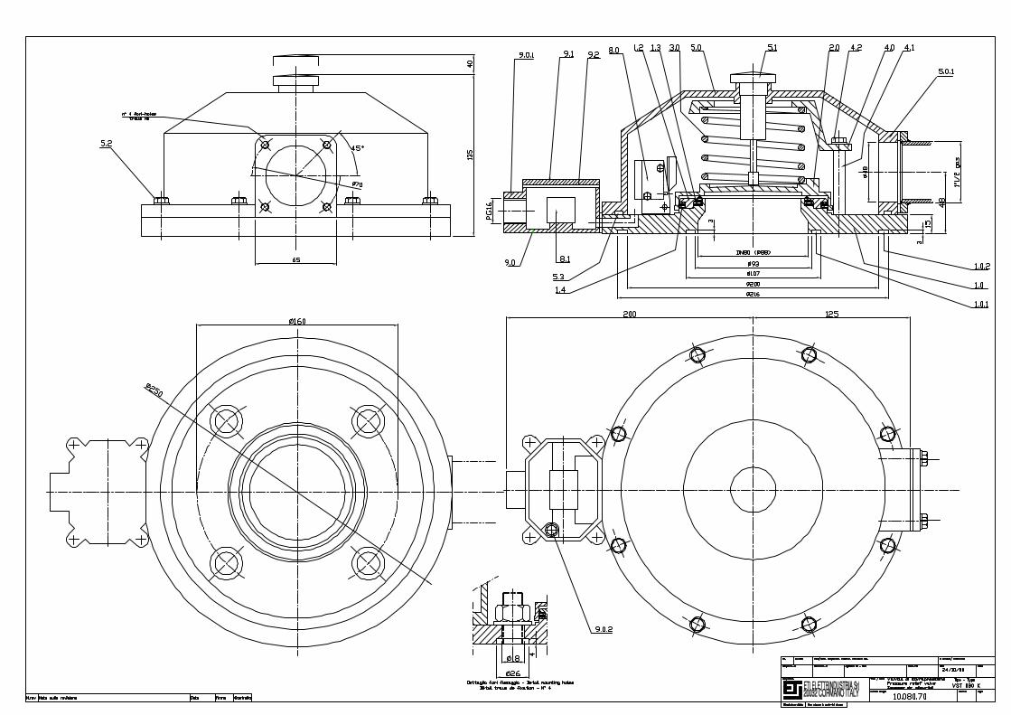
Nomenclature N°: Reference drawing N°: Page N°
Product: Revision N°:
C:\ETI\TECH\NOM\10\10VST080R00-E.doc
10VST080R00-E
Pressure relief valve Type VST 080 and VST 080 K
10.080.70 - 10.080.80 1 of 1
00 - 16.03.2002
Pos. Dénomination part N° Matériel1.0 Mounting flange 1 Aluminium G-Al-Si 13
1.0.1 Gasket seat for O-ring OR 6375 - Ø 94,63x5,34 1 See specification1.0.2 Gasket seat for O-ring OR 6795 - Ø 202,56x5,34 1 See specification
1.2 Frame for gasket assembly 1 Brass Ot 581.3 Main gasket - drawing N° 10.080.120 1 See specification1.4 Secondary gasket O-ring OR 6412 - Ø 104,1x5,34 1 See specification
2.0 Shutter 1 Aluminium G-Al-Si 13
3.0 Pressure setting spring 1 Spring steel
4.0 Spring holding rim 1 Aluminium G-Al-Si 134.1 Mounting columns for rim 4.0 4 Brass Ot 58 galvanised4.2 Screw and washer for fixation of rim 4.0 4 Stainless steel Aisi 304
5.0 Cover for oil recovery 1 Aluminium G-Al-Si 135.0.1 Flange for connection of oil recovery 1
5.1 Optical operation indicator 15.2 Screw and washer for fixation of cover 5.0 8 Stainless steel Aisi 3045.3 Gasket of cover 5.0 - O-ring OR 4825 - Ø 209,1x3,53 1 See specification
Applicable only to drawing N° 10.080.708.0 Microswitch contact, degree of protection IP 67 1/2 See specification8.1 Terminal board 1 See specification
9.0 Terminal box 1 Aluminium G-Al-Si 139.0.1 Cable entry PG16 19.0.2 Earth screw 1 Stainless steel Aisi 304
9.1 Terminal box cover 1 Aluminium G-Al-Si 139.2 Terminal box gasket 1 Nitrile rubber