Pressure relief valves - Grundfosnet.grundfos.com/Appl/WebCAPS/Grundfosliterature-3581200.pdf ·...
12
PRV Pressure relief valves Installation and operating instructions GRUNDFOS INSTRUCTIONS Other languages http://net.grundfos.com/qr/i/96681525
Transcript of Pressure relief valves - Grundfosnet.grundfos.com/Appl/WebCAPS/Grundfosliterature-3581200.pdf ·...

PRVPressure relief valves
Installation and operating instructions
GRUNDFOS INSTRUCTIONS
Other languages
http://net.grundfos.com/qr/i/96681525

En
glis
h (G
B)
English (GB) Installation and operating instructions
Original installation and operating instructions
These installation and operating instructions describe the Grundfos PRV (Pressure Relief Valve).
Sections 1-4 give the information necessary to be able to install and start up the product in a safe way.
Sections 5-10 give important information about the product as well as information on service, fault finding and disposal of the product.
CONTENTSPage
1. General information
1.1 Target group
This document is intended for the operating company and the users. It contains general instructions that must be observed before installation and during operation and maintenance of the product. The responsible staff must read these instructions prior to any work on the product.
1.1.1 Qualification and training
The persons responsible for the tasks described in this document must be appropriately qualified.
1.1.2 Obligations of the operating company
• Observe the local safety regulations.
• Keep the installation and operating instructions available at the installation location at all times.
• Coordinate the preparation of the installation location observing section 9. Technical data.
• Ensure that the users are trained for their tasks.
• Provide the stipulated safety equipment and personal protective equipment.
• Arrange regular maintenance.
1.1.3 Obligations of the user
• Observe the recognised health and safety regulations as well as the local accident prevention regulations.
• Wear protective equipment in accordance with local health and safety regulations when working on the product and handling chemicals.
• Read and understand this document.
1.2 Safe operation
If safe operation is no longer possible, the product must be taken out of operation and secured against unintentional operation.
This is the case in the following situations:
• If the product is visibly damaged.
• If the product does not seem operational.
• After long periods of storage under unfavourable conditions.
1. General information 21.1 Target group 21.1.1 Qualification and training 21.1.2 Obligations of the operating company 21.1.3 Obligations of the user 21.2 Safe operation 21.3 Symbols used in this document 3
2. Installing the product 32.1 Location 32.2 Mechanical installation 32.2.1 Installation requirements 32.2.2 Installation example 32.2.3 Pressure relief valves up to 460 l/h 42.2.4 Pressure relief valves DN 65 43. Commissioning the product 43.1 Setting the relief pressure 43.1.1 Optimal installation 53.1.2 Other installations 54. Handling and storing the product 54.1 Handling the product 54.2 Storing the product 5
5. Product introduction 55.1 Intended use 55.1.1 Improper operating methods 55.2 Identification 55.2.1 Nameplate (pressure relief valves from 60 to 460 l/h) 55.2.2 Type key 66. Maintaining the product 76.1 Maintenance schedule 76.2 Cleaning 76.3 Replacing the diaphragm 7
7. Accessories 77.1 Union nut adapters (up to 460 l/h) 77.2 Set of counter flanges for pressure relief valves DN 65 7
8. Fault finding 8
9. Technical data 89.1 Permissible media temperature 89.2 Storage and ambient temperatures 89.3 Pressure relief valves up to 60 l/h 89.3.1 Technical data 89.3.2 Materials 89.3.3 Dimensional drawings 89.4 Pressure relief valves from 60 to 460 l/h 99.4.1 Technical data 99.4.2 Materials 99.4.3 Dimensional drawings 99.5 Pressure relief valves DN 65 109.5.1 Technical data 109.5.2 Dimensional drawings 1010. Disposing of the product 10
Read this document before installing the product. Installation and operation must comply with local regulations and accepted codes of good practice.
When working with chemicals, the accident prevention regulations applicable at the installation site must be applied.
Observe the chemical manufacturer's safety data sheets when handling chemicals.
When working on the product or connections and lines, always wear protective clothing (e.g. safety goggles and gloves). The system must be pressureless.
Only operate the system if all lines are connected correctly.
2
En
gli
sh
(G
B)
1.3 Symbols used in this document
2. Installing the product
2.1 Location
• The installation location must be protected from rain, humidity, condensation, direct sunlight and dust.
• The installation location must have sufficient lighting to ensure safe operation.
• Observe the permissible ambient conditions. See section 9.2 Storage and ambient temperatures.
2.2 Mechanical installation
2.2.1 Installation requirements
Pressure relief valves are installed in the outlet line. They can also be mounted directly on the outlet valve of the dosing pump with an optional adapter.
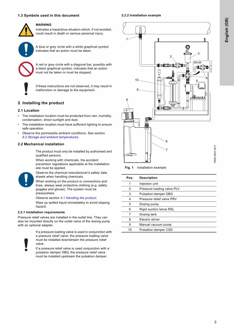
2.2.2 Installation example
Fig. 1 Installation example
WARNING
Indicates a hazardous situation which, if not avoided, could result in death or serious personal injury.
A blue or grey circle with a white graphical symbol indicates that an action must be taken.
A red or grey circle with a diagonal bar, possibly with a black graphical symbol, indicates that an action must not be taken or must be stopped.
If these instructions are not observed, it may result in malfunction or damage to the equipment.
The product must only be installed by authorised and qualified persons.
When working with chemicals, the accident prevention regulations applicable at the installation site must be applied.
Observe the chemical manufacturer's safety data sheets when handling chemicals.
When working on the product or connections and lines, always wear protective clothing (e.g. safety goggles and gloves). The system must be pressureless.
Observe section 4.1 Handling the product.
Wipe up spilled liquid immediately to avoid slipping hazard.
If a pressure loading valve is used in conjunction with a pressure relief valve, the pressure loading valve must be installed downstream the pressure relief valve.
If a pressure relief valve is used conjunction with a pulsation damper DBG, the pressure relief valve must be installed upstream the pulsation damper.
TM
06
85
02
08
17
Pos. Description
1 Injection unit
2 Pressure loading valve PLV
3 Pulsation damper DBG
4 Pressure relief valve PRV
5 Dosing pump
6 Rigid suction lance RSL
7 Dosing tank
8 Electric stirrer
9 Manual vacuum pump
10 Pulsation damper CSD
7
6
8
9
10
1
4
3
DN 65
2
5
3

En
glis
h (G
B)
2.2.3 Pressure relief valves up to 460 l/h
Pressure relief valves up to 460 l/h are designed as three-way valves. They have an inlet and an outlet on opposed sides, and an unpressurised overflow outlet. The flow direction is indicated by an arrow on the valve body.
The pressure relief valves can be installed in the outlet line, or mounted directly on the outlet valve of the dosing pump with an optional adapter, see section 7.1 Union nut adapters (up to 460 l/h).
Installing the valve in the outlet line
Observe section 2.2.1 Installation requirements.
1. Install the valve in the outlet line.
2. Connect the overflow line to the overflow outlet, and direct the unpressurised liquid to the tank or a suitable overflow.
3. Re-tighten the screws on the top part of the valve after 48 operating hours with a torque wrench. Max. torque:
Installing the valve directly on the pump
Valves up to 460 l/h can be installed directly on the pump with a special adapter. See section 7.1 Union nut adapters (up to 460 l/h).
1. Remove the connector from the inlet of the valve.
2. Screw the adapter onto the inlet of the valve.
3. Screw the valve with the adapter onto the outlet valve of the pump.
4. Connect the outlet line to the outlet of the valve.
5. Connect the overflow line to the overflow outlet, and direct the unpressurised liquid to the tank or a suitable overflow.
6. Re-tighten the screws on the top part of the valve after 48 operating hours with a torque wrench. Max. torque:
2.2.4 Pressure relief valves DN 65
Pressure relief valves DN 65 are usually designed as bypass pressure relief valves with connected T-piece for installation in the outlet line.
The relief pressure of the valve depends on the direction of installation, i.e. the direction the liquid flows through the valve (see fig. 2). The T-pieces are pre-assembled according to the selected relief pressure. See section 9. Technical data.
Fig. 2 Indication of relief pressure on valve body
Installing the valve
1. Install the T-piece with the valve in the outlet line.
2. Connect the overflow line to the pressure relief valve and direct the unpressurised liquid to the tank or a suitable overflow.
3. Commissioning the product
The relief pressure of the valve is set in the factory to the value specified in the technical data. See section 9. Technical data. During operation, the relief pressure depends on various factors, e.g. the flow, the stroke frequency of the pump, or the counterpressure. If a more precise setting is required, the valve must be adapted to the local conditions.
3.1 Setting the relief pressure
If the dosing pump does not provide counterpressure measurement, a pressure gauge must be installed in the system between the pump and the pressure relief valve.
Fig. 3 Setting the relief pressure
Install the valve in flow direction. The flow direction is indicated by an arrow on the valve body.
Up to 60 l/h 60-460 l/h DN 65
2 Nm 4 Nm 5 Nm
Up to 60 l/h 60-460 l/h DN 65
2 Nm 4 Nm 5 Nm
TM
04
83
54
07
11
4 bar
10 bar
ÖffnungsdruckOpening pressurePression de service
Flow direction
The T-piece is not always supplied as standard. There are some special versions in the form of three-way valves similar to the valves up to 60 l/h. Please always observe the corresponding dimensional drawings in section 9. Technical data!
For three-way valves proceed as described in section 2.2.3 Pressure relief valves up to 460 l/h.
The product must only be adjusted and commissioned by authorised and qualified persons.
When working with chemicals, the accident prevention regulations applicable at the installation site must be applied.
Observe the chemical manufacturer's safety data sheets when handling chemicals.
When working on the product or connections and lines, always wear protective clothing (e.g. safety goggles and gloves). The system must be pressureless.
Wipe up spilled liquid immediately to avoid slipping hazard.
WARNING
Pressurised dosing medium
Death or serious personal injury- Set the relief pressure lower than the maximum
permissible operating pressure of the dosing system.
TM
04
83
37
05
11
AB
C
4

En
gli
sh
(G
B)
3.1.1 Optimal installation
The following steps apply to installations similar to the installation example. See fig. 1.
While the pump is running:
1. Remove the protective cap from the top part of the valve.
2. Close the isolating valve behind the pressure loading valve (2).
3. When you hear the dosing medium overflowing, read the current relief pressure from the pump or the pressure gauge.
4. For valves up to 460 l/h use a hexagon wrench (A). For DN 65 valves use a pair of needle-nosed pliers (B):
– turn adjustment screw (C) clockwise to increase the pressure
– turn adjustment screw (C) counterclockwise to reduce the pressure
5. Set the desired relief pressure.
6. Open the isolating valve behind the pressure loading valve (2).
7. Attach the protective cap again.
3.1.2 Other installations
While the pump is running:
1. Remove the protective cap from the top part of the valve.
2. Set the system pressure slightly below the desired maximum operating pressure.
3. For valves up to 460 l/h use a hexagon wrench (A). For DN 65 valves use a pair of needle-nosed pliers (B):
– Turn adjustment screw (C) counterclockwise to reduce the relief pressure until medium flows over.
4. Turn adjustment screw (C) clockwise by half a turn. The relief pressure is now set slightly above the current operating pressure.
5. Attach the protective cap again.
4. Handling and storing the product
4.1 Handling the product
• Wear safety shoes during transport and installation.
• Wear a helmet if lifting the product higher than hip level.
• Use appropriate lifting and transporting equipment.
• Make sure that the product is not exposed to any point load during the transport.
• Avoid strong impacts.
• Observe the permissible ambient conditions. See section 9.2 Storage and ambient temperatures.
4.2 Storing the product
• Observe the permissible ambient conditions. See section 9.2 Storage and ambient temperatures.
• The storage location must be protected from rain, humidity, condensation, direct sunlight and dust.
5. Product introduction
5.1 Intended use
The pressure relief valve PRV protects the outlet line against impermissibly high pressure. If the pressure rises above the set relief pressure of the valve, the valve opens, and the dosing medium passing through the valve can flow back to the tank or to a suitable overflow.
The valve is suitable for liquid, non-abrasive, non-flammable and non-combustible media.
Observe the freezing and boiling points of the medium.
Make sure that parts in contact with the medium are resistant to the medium under operating conditions.
5.1.1 Improper operating methods
The operational safety of the product is only guaranteed, if it is used in accordance with section 5.1 Intended use.
The product must not be used for:
• operation in potentially explosive areas
• frozen media or gases
• crystallising media.
5.2 Identification
5.2.1 Nameplate (pressure relief valves from 60 to 460 l/h)
Fig. 4 Nameplate
The product must not be used for any other purpose than the one mentioned above.
TM
06
85
10
10
17
Pos. Description
1 Product number
2 Week and year of production
3 Type key
4 Nominal width
5 Body material
6 Gasket material
7 Factory-set relief pressure
8 Maximum operating pressure
9 Country of origin
99131032Manufactured: 09/2017PRV-G5/4-10 PVC/V,E U3nominal width: DN20material: PVCgasket: FKM, EPDMpressure release: 10.00 baroperating pressure: 10.00 bar
Made in Germany
1
2
9
45678
Grundfos Water Treatment GmbH - Reetzstr. 85 - D-76327 Pfinztal
3
5

En
glis
h (G
B)
5.2.2 Type key
Pressure relief valves up to 60 l/h
Pressure relief valves from 60 to 460 l/h
Code Description PRV- G5/8- 10 PP/ V,E U2
PRV Pressure relief valve
Connection size
G5/8 G 5/8 external thread, groove for O-ring on top
G1/4 Rp 1/4 internal thread (only SS versions)
1/4N 1/4 NPT internal thread (only SS versions)
Relief pressure
10 Preset relief pressure 10 bar
16 Preset relief pressure 16 bar
Body and connection material
PP Polypropylene
PVC Polyvinyl chloride
PV Polyvinylidene fluoride (PVDF)
SS Stainless steel, grade 1.4571 according to EN 10027-2
Gasket material
V,E FKM and EPDM gaskets are enclosed
T PTFE gaskets are enclosed
- No gaskets (only SS versions)
Hose or pipe connections
U2 Hose, 4/6 mm, 6/9 mm, 6/12 mm, 9/12 mm
U7 Hose, 0.17" x 1/4"; 1/4" x 3/8"; 3/8" x 1/2"
A Threaded connections, Rp 1/4 internal thread
V Threaded connections, 1/4 NPT internal thread
X No connections included, please order separately from accessories range
Code Description PRV- G5/4- 10 PP/ V,E U3
PRV Pressure relief valve
Connection size
G5/4 G 5/4 external thread, groove for O-ring on top
G3/4 Rp 3/4 internal thread (only SS versions)
3/4N 3/4 NPT internal thread (only SS versions)
Relief pressure
10 Preset relief pressure in bar
Body and connection material
PP Polypropylene
PVC Polyvinyl chloride
PV Polyvinylidene fluoride (PVDF)
SS Stainless steel, grade 1.4571 according to EN 10027-2
Gasket material
V,E FKM and EPDM gaskets are enclosed
T Gasket material PTFE
- No gaskets (only SS versions)
Hose or pipe connections
U3 2x Union nut, G 5/4
2x Hose connector, 19/20 mm
2x Hose clamp
2x Pipe connector, 25 mm
A7 2x Union nut, G 5/4
2x Inlay external thread 3/4 NPT
A1 Threaded connections, Rp 3/4 internal thread
A3 Threaded connections, 3/4 NPT internal thread
X No connections included, please order separately from accessories range
6

En
gli
sh
(G
B)
6. Maintaining the product6.1 Maintenance schedule
6.2 Cleaning
If necessary, clean all product surfaces with a dry and clean cloth.
6.3 Replacing the diaphragm
For service parts see service kit catalogue:
http://net.grundfos.com/qr/i/96488862_23
1. Shut down and drain the dosing system.
2. Make it impossible for a return flow or overpressure to occur.
3. Loosen the screws on the top part of the valve.
4. Remove the top part of the valve.
5. Remove the diaphragm.
6. Insert the new diaphragm.
7. Refit the top part of the valve and cross-tighten the screws with a torque wrench. Max. torque:
8. Start up the dosing system again.
9. Re-tighten the screws on the top part of the valve after 48 operating hours with a torque wrench. Max. torque:
7. Accessories
7.1 Union nut adapters (up to 460 l/h)
Union nut adapters allow direct assembly on the outlet valve of the dosing pump.
* Stainless steel 1.4571
7.2 Set of counter flanges for pressure relief valves DN 65
* Stainless steel 1.4571
The product must only be serviced by authorised and qualified persons.
When working with chemicals, the accident prevention regulations applicable at the installation site must be applied.
Observe the chemical manufacturer's safety data sheets when handling chemicals.
When working on the product or connections and lines, always wear protective clothing (e.g. safety goggles and gloves). The system must be pressureless.
Observe section 4.1 Handling the product.
Wipe up spilled liquid immediately to avoid slipping hazard.
Interval Task
After 8000 operating hours or at least every 12 months or in case of faults
If necessary, clean all product surfaces with a dry and clean cloth.
Replace the diaphragm. See section 6.3 Replacing the diaphragm.
Up to 60 l/h 60-460 l/h DN 65
2 Nm 4 Nm 5 Nm
Up to 60 l/h 60-460 l/h DN 65
2 Nm 4 Nm 5 Nm
Connections Material Product number
G 5/8 - G 5/8
PVC 95730437
PP 95730438
PVDF 95730439
G 5/8 - 1/4" SS* 96693273
G 5/4 - G 5/4
PP 99228667
PVC 99228665
PVDF 99228669
Size Material DescriptionProduct number
DN 65 PVC Set includes lapped flange, headed bush, screws,
washers, nuts
96727602
DN 65 PP 96727603
DN 65 SS*Set includes welding neck
flange, screws, washers, nuts96727604
7
En
glis
h (G
B)
8. Fault finding
9. Technical data
9.1 Permissible media temperature
9.2 Storage and ambient temperatures
9.3 Pressure relief valves up to 60 l/h
9.3.1 Technical data
9.3.2 Materials
* Stainless steel 1.4571
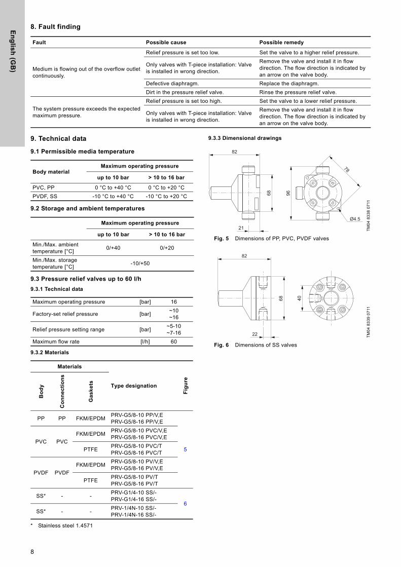
9.3.3 Dimensional drawings
Fig. 5 Dimensions of PP, PVC, PVDF valves
Fig. 6 Dimensions of SS valves
Fault Possible cause Possible remedy
Medium is flowing out of the overflow outlet continuously.
Relief pressure is set too low. Set the valve to a higher relief pressure.
Only valves with T-piece installation: Valve is installed in wrong direction.
Remove the valve and install it in flow direction. The flow direction is indicated by an arrow on the valve body.
Defective diaphragm. Replace the diaphragm.
Dirt in the pressure relief valve. Rinse the pressure relief valve.
The system pressure exceeds the expected maximum pressure.
Relief pressure is set too high. Set the valve to a lower relief pressure.
Only valves with T-piece installation: Valve is installed in wrong direction.
Remove the valve and install it in flow direction. The flow direction is indicated by an arrow on the valve body.
Body materialMaximum operating pressure
up to 10 bar > 10 to 16 bar
PVC, PP 0 °C to +40 °C 0 °C to +20 °C
PVDF, SS -10 °C to +40 °C -10 °C to +20 °C
Maximum operating pressure
up to 10 bar > 10 to 16 bar
Min./Max. ambient temperature [°C]
0/+40 0/+20
Min./Max. storage temperature [°C]
-10/+50
Maximum operating pressure [bar] 16
Factory-set relief pressure [bar]~10~16
Relief pressure setting range [bar]~5-10~7-16
Maximum flow rate [l/h] 60
Materials
Type designation
Fig
ure
Bo
dy
Co
nn
ec
tio
ns
Ga
sk
ets
PP PP FKM/EPDMPRV-G5/8-10 PP/V,EPRV-G5/8-16 PP/V,E
5
PVC PVC
FKM/EPDMPRV-G5/8-10 PVC/V,EPRV-G5/8-16 PVC/V,E
PTFEPRV-G5/8-10 PVC/TPRV-G5/8-16 PVC/T
PVDF PVDF
FKM/EPDMPRV-G5/8-10 PV/V,EPRV-G5/8-16 PV/V,E
PTFEPRV-G5/8-10 PV/TPRV-G5/8-16 PV/T
SS* - -PRV-G1/4-10 SS/-PRV-G1/4-16 SS/-
6
SS* - -PRV-1/4N-10 SS/-PRV-1/4N-16 SS/-
TM
04
83
38
07
11T
M0
4 8
33
9 0
711
Ø4.5
78
96
21
68
82
40
22
68
82
8

En
gli
sh
(G
B)
9.4 Pressure relief valves from 60 to 460 l/h
9.4.1 Technical data
9.4.2 Materials
* Stainless steel 1.4571
9.4.3 Dimensional drawings
Fig. 7 Dimensions of PP, PVC, PVDF valves
Fig. 8 Dimensions of SS valves
Maximum operating pressure [bar] 10
Factory-set relief pressure [bar] ~10
Relief pressure setting range [bar] ~3-10
Maximum flow rate [l/h] 460
Materials
Type designation
Fig
ure
Bo
dy
Co
nn
ec
tio
ns
Ga
sk
ets
PP PP FKM/EPDM PRV-G5/4-10 PP/V,E
7PVC PVC
FKM/EPDM PRV-G5/4-10 PVC/V,E
PTFE PRV-G5/4-10 PVC/T
PVDF PVDFFKM/EPDM PRV-G5/4-10 PV/V,E
PTFE PRV-G5/4-10 PV/T
SS* - - PRV-G3/4-10 SS/-8
SS* - - PRV-3/4N-10 SS/-
TM
06
85
13
08
17
A[mm]
B[mm]
C[mm]
D[mm]
E[mm]
∅F[mm]
GH
[mm]I
[mm]
168 30 92 6.5 150 85 G 5/4 40 75
TM
06
85
14
08
17
A[mm]
B[mm]
C[mm]
D ∅F[mm]
GJ
[mm]K
[mm]
167 30 63 M 6 89 Rp 3/4 10 17.5
G
E
AB
C
I
HD
ØF
AB
G
CØF
DK
G J
9

En
glis
h (G
B)
9.5 Pressure relief valves DN 65
9.5.1 Technical data
* Stainless steel 1.4571
9.5.2 Dimensional drawings
Fig. 9 Dimensions of PPH, PVC, PP valves
Fig. 10 Dimensions of SS valves with flange
Fig. 11 Drilling scheme for SS valves
10. Disposing of the productThis product or parts of it must be disposed of in an environmentally sound way:
1. Use the public or private waste collection service.
2. If this is not possible, contact the nearest Grundfos company or service workshop.
Maximum operating pressure [bar] 10
Maximum flow rate [l/h] 4000
Factory-set relief pressure
[bar]
Relief pressure setting range
[bar]
Nominal width[mm]
Body GasketL
[mm]Connection Product number Figure
~3 ~0.5 - 665 PVC FKM 266 Flange DN 65 96638461
965 PVC EPDM 266 Flange DN 65 96635243
~4 ~1-10 65 SS* PVC, soft 394 Flange DN 65 96694452 10
TM
04
83
49
07
11
L
TM
04
83
50
07
11T
M0
4 8
35
1 0
711
L
Ø170
Ø10
.5
10

Gru
nd
fos
co
mp
anie
s
ArgentinaBombas GRUNDFOS de Argentina S.A.Ruta Panamericana km. 37.500 Centro Industrial Garin1619 - Garin Pcia. de B.A.Phone: +54-3327 414 444Telefax: +54-3327 411 111
AustraliaGRUNDFOS Pumps Pty. Ltd. P.O. Box 2040 Regency Park South Australia 5942 Phone: +61-8-8461-4611 Telefax: +61-8-8340 0155
AustriaGRUNDFOS Pumpen Vertrieb Ges.m.b.H.Grundfosstraße 2 A-5082 Grödig/Salzburg Tel.: +43-6246-883-0 Telefax: +43-6246-883-30
BelgiumN.V. GRUNDFOS Bellux S.A. Boomsesteenweg 81-83 B-2630 Aartselaar Tél.: +32-3-870 7300 Télécopie: +32-3-870 7301
BelarusПредставительство ГРУНДФОС в Минске220125, Минскул. Шафарнянская, 11, оф. 56Тел.: +7 (375 17) 286 39 72, 286 39 73Факс: +7 (375 17) 286 39 71E-mail: [email protected]
Bosnia/HerzegovinaGRUNDFOS SarajevoTrg Heroja 16,BiH-71000 SarajevoPhone: +387 33 713 290Telefax: +387 33 659 079e-mail: [email protected]
BrazilBOMBAS GRUNDFOS DO BRASILAv. Humberto de Alencar Castelo Branco, 630CEP 09850 - 300São Bernardo do Campo - SPPhone: +55-11 4393 5533Telefax: +55-11 4343 5015
BulgariaGrundfos Bulgaria EOODSlatina DistrictIztochna Tangenta street no. 100BG - 1592 SofiaTel. +359 2 49 22 200Fax. +359 2 49 22 201email: [email protected]
CanadaGRUNDFOS Canada Inc. 2941 Brighton Road Oakville, Ontario L6H 6C9 Phone: +1-905 829 9533 Telefax: +1-905 829 9512
ChinaGrundfos AlldosDosing & DisinfectionALLDOS (Shanghai) Water Technology Co. Ltd.West Unit, 1 Floor, No. 2 Building (T 4-2)278 Jinhu Road, Jin Qiao Export Processing ZonePudong New Area Shanghai, 201206Phone: +86 21 5055 1012Telefax: +86 21 5032 0596E-mail: [email protected]
ChinaGRUNDFOS Pumps (Shanghai) Co. Ltd.10F The Hub, No. 33 Suhong RoadMinhang DistrictShanghai 201106PRCPhone: +86-21 6122 5222 Telefax: +86-21 6122 5333
COLOMBIAGRUNDFOS Colombia S.A.S.Km 1.5 vía Siberia-Cota Conj. Potrero Chico,Parque Empresarial Arcos de Cota Bod. 1A.Cota, CundinamarcaPhone: +57(1)-2913444Telefax: +57(1)-8764586
CroatiaGRUNDFOS CROATIA d.o.o.Cebini 37, BuzinHR-10010 ZagrebPhone: +385 1 6595 400 Telefax: +385 1 6595 499www.hr.grundfos.com
GRUNDFOS Sales Czechia and Slovakia s.r.o.Čapkovského 21779 00 OlomoucPhone: +420-585-716 111
DenmarkGRUNDFOS DK A/S Martin Bachs Vej 3 DK-8850 Bjerringbro Tlf.: +45-87 50 50 50 Telefax: +45-87 50 51 51 E-mail: [email protected]/DK
EstoniaGRUNDFOS Pumps Eesti OÜPeterburi tee 92G11415 TallinnTel: + 372 606 1690Fax: + 372 606 1691
FinlandOY GRUNDFOS Pumput AB Trukkikuja 1FI-01360 Vantaa Phone: +358-(0)207 889 500
FrancePompes GRUNDFOS Distribution S.A. Parc d’Activités de Chesnes 57, rue de Malacombe F-38290 St. Quentin Fallavier (Lyon) Tél.: +33-4 74 82 15 15 Télécopie: +33-4 74 94 10 51
GermanyGRUNDFOS Water Treatment GmbHReetzstraße 85D-76327 Pfinztal (Söllingen)Tel.: +49 7240 61-0 Telefax: +49 7240 61-177E-mail: [email protected]
GermanyGRUNDFOS GMBHSchlüterstr. 3340699 ErkrathTel.: +49-(0) 211 929 69-0 Telefax: +49-(0) 211 929 69-3799E-mail: [email protected] in Deutschland:E-mail: [email protected]
GreeceGRUNDFOS Hellas A.E.B.E. 20th km. Athinon-Markopoulou Av. P.O. Box 71 GR-19002 Peania Phone: +0030-210-66 83 400 Telefax: +0030-210-66 46 273
Hong KongGRUNDFOS Pumps (Hong Kong) Ltd. Unit 1, Ground floor Siu Wai Industrial Centre 29-33 Wing Hong Street & 68 King Lam Street, Cheung Sha Wan Kowloon Phone: +852-27861706 / 27861741 Telefax: +852-27858664
HungaryGRUNDFOS Hungária Kft.Park u. 8H-2045 Törökbálint, Phone: +36-23 511 110Telefax: +36-23 511 111
IndiaGRUNDFOS Pumps India Private Limited118 Old Mahabalipuram RoadThoraipakkamChennai 600 097Phone: +91-44 4596 6800
IndonesiaPT. GRUNDFOS POMPAGraha Intirub Lt. 2 & 3Jln. Cililitan Besar No.454. Makasar, Jakarta TimurID-Jakarta 13650Phone: +62 21-469-51900Telefax: +62 21-460 6910 / 460 6901
IrelandGRUNDFOS (Ireland) Ltd. Unit A, Merrywell Business ParkBallymount Road LowerDublin 12 Phone: +353-1-4089 800 Telefax: +353-1-4089 830
ItalyGRUNDFOS Pompe Italia S.r.l. Via Gran Sasso 4I-20060 Truccazzano (Milano)Tel.: +39-02-95838112 Telefax: +39-02-95309290 / 95838461
JapanGRUNDFOS Pumps K.K.1-2-3, Shin-Miyakoda, Kita-kuHamamatsu431-2103 JapanPhone: +81 53 428 4760Telefax: +81 53 428 5005
KoreaGRUNDFOS Pumps Korea Ltd.6th Floor, Aju Building 679-5Yeoksam-dong, Kangnam-ku, 135-916Seoul, KoreaPhone: +82-2-5317 600Telefax: +82-2-5633 725
LatviaSIA GRUNDFOS Pumps Latvia Deglava biznesa centrsAugusta Deglava ielā 60, LV-1035, Rīga,Tālr.: + 371 714 9640, 7 149 641Fakss: + 371 914 9646
LithuaniaGRUNDFOS Pumps UABSmolensko g. 6LT-03201 VilniusTel: + 370 52 395 430Fax: + 370 52 395 431
MalaysiaGRUNDFOS Pumps Sdn. Bhd.7 Jalan Peguam U1/25Glenmarie Industrial Park40150 Shah AlamSelangor Phone: +60-3-5569 2922Telefax: +60-3-5569 2866
MexicoBombas GRUNDFOS de México S.A. de C.V. Boulevard TLC No. 15Parque Industrial Stiva AeropuertoApodaca, N.L. 66600Phone: +52-81-8144 4000 Telefax: +52-81-8144 4010
NetherlandsGRUNDFOS NetherlandsVeluwezoom 351326 AE AlmerePostbus 22015 1302 CA ALMERE Tel.: +31-88-478 6336 Telefax: +31-88-478 6332 E-mail: [email protected]
New ZealandGRUNDFOS Pumps NZ Ltd.17 Beatrice Tinsley CrescentNorth Harbour Industrial EstateAlbany, AucklandPhone: +64-9-415 3240Telefax: +64-9-415 3250
NorwayGRUNDFOS Pumper A/S Strømsveien 344 Postboks 235, Leirdal N-1011 Oslo Tlf.: +47-22 90 47 00 Telefax: +47-22 32 21 50
PolandGRUNDFOS Pompy Sp. z o.o.ul. Klonowa 23Baranowo k. PoznaniaPL-62-081 PrzeźmierowoTel: (+48-61) 650 13 00Fax: (+48-61) 650 13 50
PortugalBombas GRUNDFOS Portugal, S.A. Rua Calvet de Magalhães, 241Apartado 1079P-2770-153 Paço de ArcosTel.: +351-21-440 76 00Telefax: +351-21-440 76 90
RomaniaGRUNDFOS Pompe România SRLBd. Biruintei, nr 103 Pantelimon county IlfovPhone: +40 21 200 4100Telefax: +40 21 200 4101E-mail: [email protected]
RussiaООО Грундфосул. Школьная, 39-41Москва, RU-109544, RussiaТел. (+7) 495 737 30 00, 564 8800Факс (+7) 495 737 75 36, 564 8811E-mail [email protected]
Serbia GRUNDFOS Predstavništvo BeogradDr. Milutina Ivkovića 2a/29YU-11000 Beograd Phone: +381 11 26 47 877 / 11 26 47 496Telefax: +381 11 26 48 340
SingaporeGRUNDFOS (Singapore) Pte. Ltd. 25 Jalan Tukang Singapore 619264 Phone: +65-6681 9688 Telefax: +65-6681 9689
SlovakiaGRUNDFOS s.r.o.Prievozská 4D 821 09 BRATISLAVA Phona: +421 2 5020 1426sk.grundfos.com
SloveniaGRUNDFOS LJUBLJANA, d.o.o.Leskoškova 9e, 1122 LjubljanaPhone: +386 (0) 1 568 06 10Telefax: +386 (0)1 568 0619E-mail: [email protected]
South AfricaGrundfos (PTY) Ltd.Corner Mountjoy and George Allen RoadsWilbart Ext. 2Bedfordview 2008Phone: (+27) 11 579 4800Fax: (+27) 11 455 6066E-mail: [email protected]
SpainBombas GRUNDFOS España S.A. Camino de la Fuentecilla, s/n E-28110 Algete (Madrid) Tel.: +34-91-848 8800 Telefax: +34-91-628 0465
SwedenGRUNDFOS AB (Box 333) Lunnagårdsgatan 6 431 24 Mölndal Tel.: +46 31 332 23 000 Telefax: +46 31-331 94 60
SwitzerlandGRUNDFOS ALLDOS International AGSchönmattstraße 4 CH-4153 ReinachTel.: +41-61-717 5555Telefax: +41-61-717 5500E-mail: [email protected]
SwitzerlandGRUNDFOS Pumpen AG Bruggacherstrasse 10 CH-8117 Fällanden/ZH Tel.: +41-44-806 8111 Telefax: +41-44-806 8115
TaiwanGRUNDFOS Pumps (Taiwan) Ltd. 7 Floor, 219 Min-Chuan Road Taichung, Taiwan, R.O.C. Phone: +886-4-2305 0868Telefax: +886-4-2305 0878
ThailandGRUNDFOS (Thailand) Ltd. 92 Chaloem Phrakiat Rama 9 Road,Dokmai, Pravej, Bangkok 10250Phone: +66-2-725 8999Telefax: +66-2-725 8998
TurkeyGRUNDFOS POMPA San. ve Tic. Ltd. Sti.Gebze Organize Sanayi Bölgesi Ihsan dede Caddesi,2. yol 200. Sokak No. 20441490 Gebze/ KocaeliPhone: +90 - 262-679 7979Telefax: +90 - 262-679 7905E-mail: [email protected]
UkraineБізнес Центр ЄвропаСтоличне шосе, 103м. Київ, 03131, Україна Телефон: (+38 044) 237 04 00 Факс.: (+38 044) 237 04 01E-mail: [email protected]
United Arab EmiratesGRUNDFOS Gulf DistributionP.O. Box 16768Jebel Ali Free ZoneDubaiPhone: +971-4- 8815 166Telefax: +971-4-8815 136
United KingdomGRUNDFOS Pumps Ltd. Grovebury Road Leighton Buzzard/Beds. LU7 4TL Phone: +44-1525-850000 Telefax: +44-1525-850011
U.S.A.GRUNDFOS Pumps Corporation 17100 West 118th TerraceOlathe, Kansas 66061Phone: +1-913-227-3400 Telefax: +1-913-227-3500
UzbekistanGrundfos Tashkent, Uzbekistan The Representative Office of Grundfos Kazakhstan in Uzbekistan 38a, Oybek street, Tashkent Телефон: (+998) 71 150 3290 / 71 150 3291Факс: (+998) 71 150 3292
Addresses revised 09.08.2017

96681525 0218
ECM: 1224038 The
nam
e G
rund
fos,
the
Gru
ndfo
s lo
go, a
nd b
e t
hin
k i
nn
ov
ate
are
regi
ster
ed tr
adem
arks
ow
ned
by G
rund
fos
Hol
ding
A/S
or G
rund
fos
A/S,
Den
mar
k. A
ll rig
hts
rese
rved
wor
ldw
ide.
© C
opyr
ight
Gru
ndfo
s H
oldi
ng A
/S
www.grundfos.com