Pressure reducing valve, oil pilot operated oil · HETG NBR, FKM ISO 15380 HEES FKM – Soluble in...
12
1/12 Information on available spare parts: www.boschrexroth.com/spc Pressure reducing valve, pilot operated Type DR RE 26892/05.11 Replaces: 02.03 Table of contents Features – For subplate mounting – Porting pattern according to ISO 5781 – For threaded connection – As cartridge valve – 4 adjustment types, optional: • Rotary knob • Bushing with hexagon and protective cap • Lockable rotary knob with scale • Rotary knob with scale – 5 pressure ratings – Check valve, optional (only subplate mounting) – More information: • Subplates Data sheet 45062 Contents Page Features 1 Ordering code 2 Symbols 2 Function, section 3 Technical data 4 Characteristic curves 5 to 7 Unit dimensions 8 to 11 Installation bore 12 K4660/9 Size 10 to 32 Component series 5X Maximum operating pressure 350 bar Maximum flow 400 l/min
Transcript of Pressure reducing valve, oil pilot operated oil · HETG NBR, FKM ISO 15380 HEES FKM – Soluble in...

1/12
Information on available spare parts: www.boschrexroth.com/spc
Pressure reducing valve, pilot operated
Type DR
RE 26892/05.11Replaces: 02.03
Table of contents Features
– For subplate mounting– Porting pattern according to ISO 5781– For threaded connection– As cartridge valve– 4 adjustment types, optional: •Rotaryknob •Bushingwithhexagonandprotectivecap •Lockablerotaryknobwithscale •Rotaryknobwithscale
– 5 pressure ratings– Checkvalve,optional(onlysubplatemounting)
– More information:
• Subplates Data sheet 45062
Contents PageFeatures 1Ordering code 2Symbols 2Function, section 3Technical data 4Characteristic curves 5 to 7Unit dimensions 8 to 11Installation bore 12
K4660/9
Size 10 to 32Component series 5XMaximum operating pressure 350 barMaximum flow 400 l/min
InhaltTable of contents 1Features 1Ordering code 2Symbols 2Function, section 3Technical Data(Forapplicationsoutsidetheseparameters,pleaseconsultus!) 4Characteristic curves(measuredwithHLP46,ϑoil = 40 °C ± 5 °C) 5Characteristic curves(measuredwithHLP46,ϑoil = 40 °C ± 5 °C) 6Characteristic curves(measuredwithHLP46,ϑoil = 40 °C ± 5 °C) 7Unit dimensions: TypeDRC…;cartridgevalve(dimensionsinmm) 8Unit dimensions: TypeDR…;threadedconnection(dimensionsinmm) 9Unit dimensions: TypeDR…;subplatemounting(dimensionsinmm) 10Unit dimensions 11Installation bore (dimensionsinmm) 12

2/12 Bosch Rexroth AG Hydraulics DR RE 26892/05.11
Ordering code
Complete valve = no code (Subplatemountingorthreadedconnection)Pilot valve = C without mainspoolinsert(cartridgevalve) (donot entersize)Pilot valve = C with mainspoolinsert(cartridgevalve) (entervalvesize30)
Size
Ordering codeSubplate
mounting "–"Threaded
connection "G"10 = 10 = 10(G1/2)16 – = 15(G3/4)25 = 20 = 20(G1)25 – = 25(G11/4)32 = 30 = 30(G11/2)
As cartridge valve = no code (version"C",withoutmainspoolinsert)As cartridge valve = – (version"C",withmainspoolinsert)For subplate mounting = –For threaded connection = GAdjustment type for pressure adjustmentRotaryknob = 4Bushingwithhexagonandprotectivecap = 5 (alwayswithmaximumpressureadjustment)Lockablerotaryknobwithscale = 61)
Rotaryknobwithscale = 7
1) H-keywithMaterialno.R900008158 is included in the delivery.
Further details in the plain textSeal material
No code = NBRsealsV = FKM seals
(othersealsuponrequest)Attention!
Observe compatibility of seals with hydraulic fluid used!
No code = With checkvalve (onlyforsubplatemounting)
M = Without checkvalve Pilot oil supplyY = Pilot oil supply internal,
pilot oil return external50 = Set pressure up to 50 bar100 = Set pressure up to 100 bar200 = Set pressure up to 200 bar315 = Set pressure up to 315 bar350 = Set pressure up to 350 bar
(onlyversion"M")5X = Component series 50 to 59 (50to59:unchangedinstallationandconnectiondimensions)
DR 5X Y *
Symbols
Type DR…YM Type DR…Y
B
A Y
B
A Y
AB
16
a a
A B Y
5
1
438
7
17
2
9 10 6 11 14
12
13
15
Hydraulics Bosch Rexroth AGRE 26892/05.11 DR 3/12
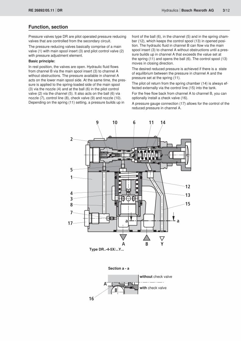
Function, section
Pressure valves type DR are pilot operated pressure reducing valves that are controlled from the secondary circuit.The pressure reducing valves basically comprise of a main valve(1)withmainspoolinsert(3)andpilotcontrolvalve(2)with pressure adjustment element.Basic principle:Inrestposition,thevalvesareopen.HydraulicfluidflowsfromchannelBviathemainspoolinsert(3)tochannelAwithout obstructions. The pressure available in channel A acts on the lower main spool side. At the same time, the pres-sureisappliedtothespring-loadedsideofthemainspool(3)viathenozzle(4)andattheball(6)inthepilotcontrolvalve(2)viathechannel(5).Italsoactsontheball(6)vianozzle(7),controlline(8),checkvalve(9)andnozzle(10).Dependingonthespring(11)setting,apressurebuildsupin
frontoftheball(6),inthechannel(5)andinthespringcham-ber(12),whichkeepsthecontrolspool(13)inopenedposi-tion.ThehydraulicfluidinchannelBcanflowviathemainspoolinsert(3)tochannelAwithoutobstructionsuntilapres-sure builds up in channel A that exceeds the value set at thespring(11)andopenstheball(6).Thecontrolspool(13)moves in closing direction.The desired reduced pressure is achieved if there is a state ofequilibriumbetweenthepressureinchannelAandthepressuresetatthespring(11).Thepilotoilreturnfromthespringchamber(14)isalwaysef-fectedexternallyviathecontrolline(15)intothetank.ForthefreeflowbackfromchannelAtochannelB,youcanoptionallyinstallacheckvalve(16).Apressuregaugeconnection(17)allowsforthecontrolofthereduced pressure in channel A.
Type DR..-4-5X/...Y...
withoutcheckvalve
withcheckvalve
Section a - a

4/12 Bosch Rexroth AG Hydraulics DR RE 26892/05.11
Technical Data(Forapplicationsoutsidetheseparameters,pleaseconsultus!)
generalSize 10 16 25
(typeDR..20)25
(typeDR..25)32
Weight Subplate mounting – Type DR . .– kg 3.4 – 5.3 – 8.0Cartridge valve – Type DRC kg 1.2
– Type DRC 30 kg 1.5Threaded connection –TypeDR..G kg 5.3 5.2 5.1 5.0 4.8
Installation position AnyAmbient temperature range °C –30to+50(NBRseals)
–20to+50(FKMseals)
hydraulicMaximum operating pressure –PortB bar 3501)
Maximum inlet pressure –PortB bar 3501)
Maximum outlet pressure – Port … bar 3501)
Operating pressure range – Port A bar 10 to 350 1)
Maximumbackpressure – Port Y bar 3501)
Minimal set pressure bar Flow-dependent(seecharacteristiccurvespage5)Maximum set pressure bar 50; 100; 200; 315; 3501)
Maximum flow – Subplate mounting l/min 150 – 300 – 400– Threaded connection l/min 150 300 300 400 400
Hydraulicfluid See table belowHydraulicfluidtemperaturerange °C –30to+80(NBRseals)
–20to+80(FKMseals)Viscosity range mm2/s 10 to 800Maximum permitted degree of contamination of the hydraulic fluid-cleanlinessclassaccordingtoISO4406(c)
Class 20/18/152)
1)350baronlypossiblewithversionwithoutcheckvalve 2) The cleanliness classes specified for the components must be adhered to in hydraulic systems. Effective filtration pre-vents faults and at the same time increases the service life of the components.
For the selection of the filters see www.boschrexroth.com/filter.
Hydraulic fluid Classification Suitable sealing materials StandardsMineral oils and related hydrocarbons HL,HLP,HLPD NBR,FKM DIN 51524
Environmentally compatible
– Insoluble in waterHETG NBR,FKM
ISO 15380HEES FKM
– Soluble in water HEPG FKM ISO 15380
Flame-resistant– Water-free HFDU,HFDR FKM ISO 12922
– Water-containing HFC(FuchsHydrotherm46M,PetroferUltraSafe620) NBR ISO 12922
Important information on hydraulic fluids!– For more information and data on the use of other hydrau-
lic fluids refer to data sheet 90220 or contact us!– There may be limitations regarding the technical valve data(temperature,pressurerange,servicelife,mainte-nanceintervals,etc.)!
– Flame-resistant – water-containing: •Maximumoperatingpressure210bar•Maximumhydraulicfluidtemperature60°C• ExpectedservicelifeascomparedtoHLPhydraulicoil
30 % to 100 %

50 100 150 250 400
50
100
200
250
300
150
300
350
200 350
315
1 2 3
00
2
4
8
10
14
6
16
12
5 6
7
1 2 3
050 100 150 250 400300200 3500
4
Hydraulics Bosch Rexroth AGRE 26892/05.11 DR 5/12
Outlet pressure pA depending on the flow qV (B to A)
Flow in l/min →
Out
let p
ress
ure
in b
ar →
Flow in l/min →
Redu
ced
pres
sure
in b
ar →
Minimum set pressure with pA min depending on the flow qV (B to A)
1 Size 102 Size 253 Size 32
1 Size 102 Size 253 Size 324 pA min
Performance limit (system-dependent)5 Size 106 Size 257 Size 32
Characteristic curves(measuredwithHLP46,ϑoil=40°C±5°C)
The characteristic curves apply to the pressure at the valve output pT = 0 bar across the entire flow range.

2
4
8
10
14
6
12
1
2 3
50 100 150 250 400300200 3500
0,5
1,0
1,5
1 2 3
50 100 150 250 400300200 35000
4
5
6/12 Bosch Rexroth AG Hydraulics DR RE 26892/05.11
∆p-qV characteristic curves (B to A; lowest pressure differential adjustable)
Flow in l/min →
Pres
sure
diff
eren
tial in
bar
→
Flow in l/min →
Pilo
t flo
w in
l/m
in →
Pilot flow depending on flow (B to A) and pressure differential
Characteristic curves(measuredwithHLP46,ϑoil=40°C±5°C)
1 Size 102 Size 253 Size 32
1 Size 102 Size 253 Size 324 ∆p = 50 bar5 ∆p = 200 bar
10
20
30
15
25
5
1
2 3
050 100 150 250 400300200 3500
Hydraulics Bosch Rexroth AGRE 26892/05.11 DR 7/12
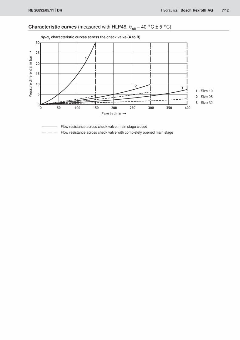
∆p-qV characteristic curves across the check valve (A to B)
Flow in l/min →
Pres
sure
diff
eren
tial in
bar
→Characteristic curves(measuredwithHLP46,ϑoil=40°C±5°C)
Flowresistanceacrosscheckvalve,mainstageclosedFlowresistanceacrosscheckvalvewithcompletelyopenedmainstage
1 Size 102 Size 253 Size 32

Y
4 7 3 5; 6 82.2
1
21
09
8
3
4029
X Y
1011
16
1415
1213
285161
35
11,5
32 44
3129
4
98,4
37,56
49110
118145
169 18
G1/4; 12
5
2
323520
39,5
2.1
8/12 Bosch Rexroth AG Hydraulics DR RE 26892/05.11
Unit dimensions: TypeDRC…;cartridgevalve(dimensionsinmm)
1 Name plate2.1 Y port for pilot oil return external2.2 Y port optionally for pilot oil return external
3 Adjustmenttype"4"4 Adjustmenttype"5"5 Adjustmenttype"6"6 Adjustmenttype"7"7 HexagonSW108 Spacerequiredtoremovethekey9 Valve mounting bores
10 Seal rings11 Main spool insert12 Seal ring13 Seal ring14 Seal ring15 Support ring16 Support ring
Valve mounting screws (separateorder)4 hexagon socket head cap screws ISO 4762 - M8 x 40 - 10.9-flZn-240h-L with friction coefficient µtotal = 0.09 to 0.14, TighteningtorqueMA = 31 Nm ±10 %, Material No. R913000205
Installation bore, see page 12.

90
Ø32
49
Ø35
110118
145169 18
5
4413
4
20
114D
1
Y
2
T11
47
56
72
T1
1
D1
5 17
80 Ø72
B
A
11
G1/4; 12
Ø25
G1/4; 12
5,5
ØD2
ØD
2
Ø39
,5
4 7 3 5; 6 82.1
17
9
1
21
09
8
3
Hydraulics Bosch Rexroth AGRE 26892/05.11 DR 9/12
Unit dimensions: TypeDR…;threadedconnection(dimensionsinmm)
Size D1 ØD2 T110 G1/2 34 1416(TypeDR15G…) G3/4 42 1625(TypeDR20G…) G1 47 1825(TypeDR25G…) G11/4 58 2032(TypeDR30G…) G11/2 65 22
1 Name plate2.1 Y port for pilot oil return external
3 Adjustmenttype"4"4 Adjustmenttype"5"5 Adjustmenttype"6"6 Adjustmenttype"7"7 HexagonSW108 Spacerequiredtoremovethekey9 Valve mounting bores
17 Pressure gauge connection

32
49
35
110118
145169 18
5
H1
20Y
2
G1/4; 12
39,5
4 7 3 5; 6 82.2
21
09
8
3
Y
5
16
6 5
H3
H2
A B
Y
L6L5L3
L4L2L15
B2B1
X
L7L8
L9L10
29B5
B4 B3
11 9
G1/4; 1217 18 2.1
9
1 19 20
A
0,01/100
Rzmax 4
10/12 Bosch Rexroth AG Hydraulics DR RE 26892/05.11
Unit dimensions: TypeDR…;subplatemounting(dimensionsinmm)
Size L1 L2 L3 L4 L5 L6 L7 L8 L9 L1010 96 35.5 33 42.9 21.5 – 7.2 21.5 31.8 35.825 116 37.5 35.4 60.3 39.7 – 11.1 20.6 44.5 49.232 145 33 29.8 84.2 59.5 42.1 16.7 24.6 62.7 67.5
Size B1 B2 B3 B4 B5 H1 H2 H310 85 50 66.7 58.8 7.9 112 92 2825 102 59.5 79.4 73 6.4 122 102 3832 120 76 96.8 92.8 3.8 130 110 46
Item explanations, subplates, and valve mounting screws, see page 11.
Requiredsurfacequalityofthevalve mounting face

Hydraulics Bosch Rexroth AGRE 26892/05.11 DR 11/12
Unit dimensions
1 Name plate2.1 Y port for pilot oil return external2.2 Y port optionally for pilot oil return external
3 Adjustmenttype"4"4 Adjustmenttype"5"5 Adjustmenttype"6"6 Adjustmenttype"7"7 HexagonSW108 Spacerequiredtoremovethekey9 Valve mounting bore
17 Pressure gauge connection18 IdenticalsealringsforportsAandB;
identical seal rings for ports X and Y19 PortBwithoutfunction(blindhole)20 Locatingpin
Subplate mounting:Subplates according to data sheet 45062 (separateorder)–Size10 G460/01(G3/8) G461/01(G1/2) –Size20 G412/01(G3/4) G413/01(G1) –Size30 G414/01(G11/4) G415/01(G11/2)
Valve mounting screws(separateorder)– Size 10
4 hexagon socket head cap screws metric ISO 4762 - M10 x 50 - 10.9-flZn-240h-L with friction coefficient µtotal = 0.09 to 0.14, TighteningtorqueMA = 60 Nm ±10 %, Material no. R913000471
– Size 20 4 ISO 4762 - M10 x 60 - 10.9-flZn-240h-L with friction coefficient µtotal = 0.09 to 0.14, TighteningtorqueMA = 60 Nm ±10 %, Material no. R913000116
– Size 30 6 ISO 4762 - M10 x 70 - 10.9-flZn-240h-L with friction coefficient µtotal = 0.09 to 0.14, TighteningtorqueMA = 60 Nm ±10 %, Material no. R913000126

B
28,5+0,132H745
29 0,2 26 0,2
A
X Y
B
0,00
8
B0,
052
x 45
2 x
45
4
Rz 8
Rz 16
max R0,3
6
M4; 6
A
18
24,8+0,2
Rz 8
4 2 x
30
25,5
17
340,
01/1
0032 40
+0,
1
42+
0,1
+0,
05
51,5
0,1
55
Rzmax 4
A0,02
2 13
“Z”
32
X Y
61
44
4 x M8; 121651
32
BoschRexrothAG HydraulicsZum Eisengießer 197816LohramMain,Germany Phone +49(0)9352/18-0 Fax +49(0)9352/[email protected] www.boschrexroth.de
© This document, as well as the data, specifications and other informa-tionsetforthinit,aretheexclusivepropertyofBoschRexrothAG.Itmay not be reproduced or given to third parties without its consent.The data specified above only serve to describe the product. No state-ments concerning a certain condition or suitability for a certain applica-tion can be derived from our information. The information given does not release the user from the obligation of own judgment and verification. It must be remembered that our products are subject to a natural process of wear and aging.
12/12 Bosch Rexroth AG Hydraulics DR RE 26892/05.11
Installation bore (dimensionsinmm)
View "Z"
1 Note! The Ø32 bore can tap a Ø45 bore atanypoint.However,itmustbe observed that the connection bores and the valve mounting bores are not damaged!
2 A support ring and seal rings must be inserted into the bore before assembly of the main spool
3 Nozzle, separate order