
Pressure Points - Control Voltagecontrolvoltage.net/manuals/makenoise/PressurePoints.pdf ·...
8
Pressure Points
Transcript of Pressure Points - Control Voltagecontrolvoltage.net/manuals/makenoise/PressurePoints.pdf ·...
Pressure Points

Limited WARRANTY:Make Noise warrants this product to be free of defects in materials or construction for a period of one year from the date of manufacture.
Malfunction resulting from wrong power supply voltages, backwards power cable connection, abuse of the product or any other causes determined by Make Noise to be the fault of the user are not covered by this warranty, and normal service rates will apply.
During the warranty period, any defective products will be repaired or replaced, at the option of Make Noise, on a return-to-Make Noise basis, with the customer paying the transit cost to Make Noise. Please contact Make Noise for Return To Manufacturer Authorization.
Make Noise implies and accepts no responsibility for harm to person or apparatus caused through operation of this product.
Please contact [email protected] with any questions, needs & comments, otherwise...
go MAKE NOISE.
http://www.makenoisemusic.com
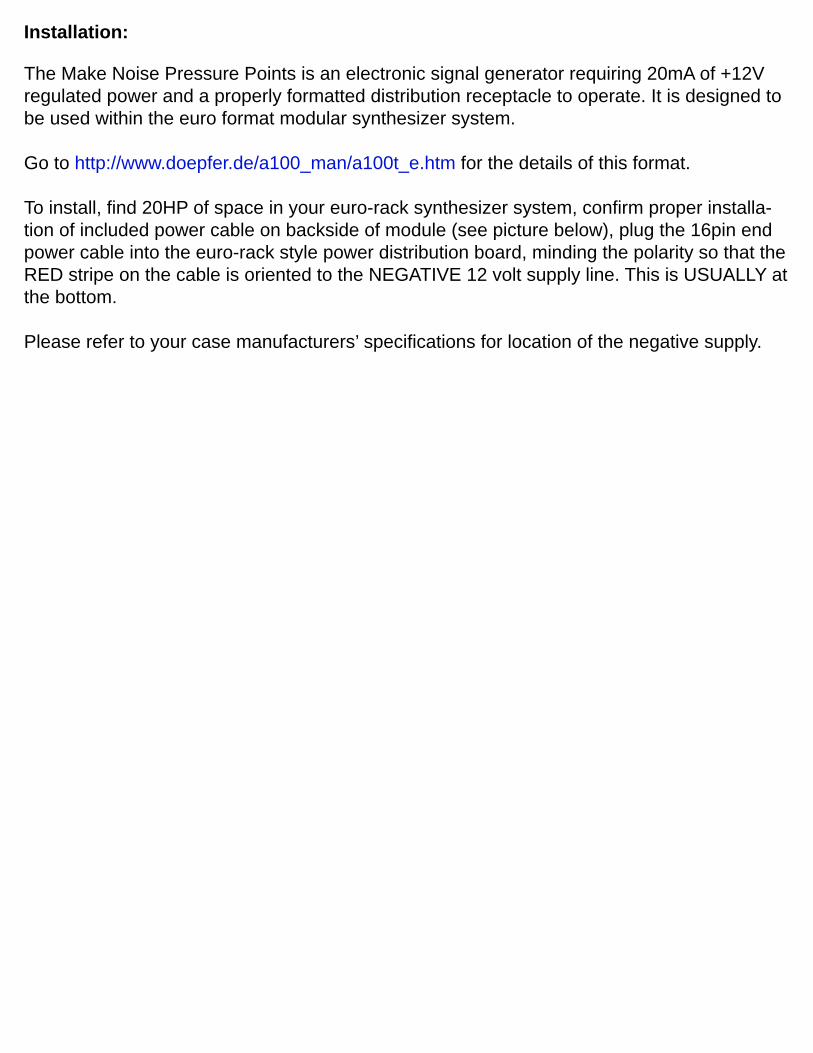
Installation:
The Make Noise Pressure Points is an electronic signal generator requiring 20mA of +12V regulated power and a properly formatted distribution receptacle to operate. It is designed to be used within the euro format modular synthesizer system.
Go to http://www.doepfer.de/a100_man/a100t_e.htm for the details of this format.
To install, find 20HP of space in your euro-rack synthesizer system, confirm proper installa-tion of included power cable on backside of module (see picture below), plug the 16pin end power cable into the euro-rack style power distribution board, minding the polarity so that the RED stripe on the cable is oriented to the NEGATIVE 12 volt supply line. This is USUALLY at the bottom.
Please refer to your case manufacturers’ specifications for location of the negative supply.

Single Pressure Points with no BRAINS attached. Note all the "Close 4 Master" locations are closed, as well as the Expand headers.
Jumper and Cable Connections:(Power connections for each module not shown for clarity.)
Two Pressure Points, chained. Note that the "Close 4 Master" headers are closed on the first unit (will be on the right when installed in the case). For three or four Pressure Points, use 4-header CHAIN cable and leave "Close 4 Master" headers open on all units but the master (rightmost when installed/leftmost from behind). Also, note the jumpers on the EXPAND headers.
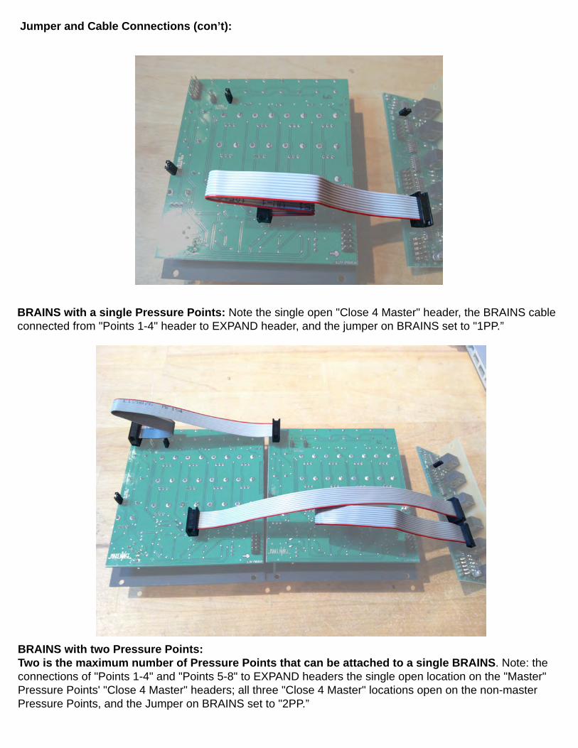
BRAINS with a single Pressure Points: Note the single open "Close 4 Master" header, the BRAINS cable connected from "Points 1-4" header to EXPAND header, and the jumper on BRAINS set to "1PP.”
Jumper and Cable Connections (con’t):
BRAINS with two Pressure Points:Two is the maximum number of Pressure Points that can be attached to a single BRAINS. Note: the connections of "Points 1-4" and "Points 5-8" to EXPAND headers the single open location on the "Master" Pressure Points' "Close 4 Master" headers; all three "Close 4 Master" locations open on the non-master Pressure Points, and the Jumper on BRAINS set to "2PP.”
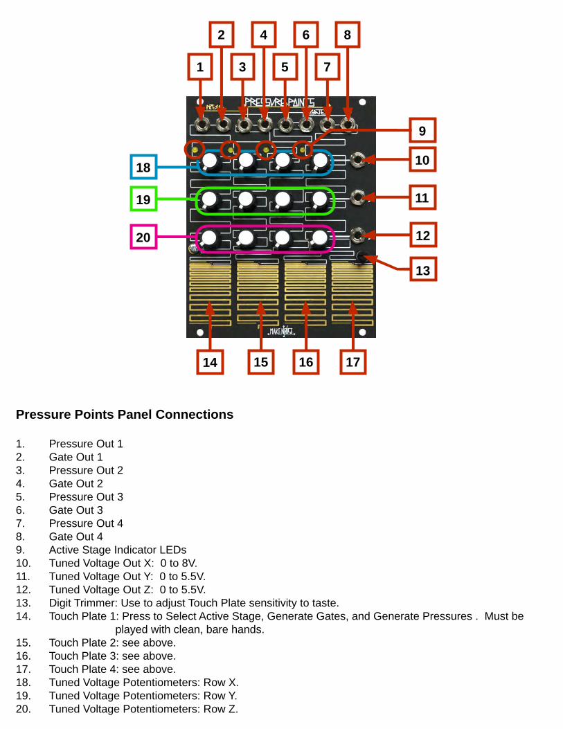
Pressure Points Panel Connections
1. Pressure Out 12. Gate Out 13. Pressure Out 24. Gate Out 25. Pressure Out 36. Gate Out 37. Pressure Out 48. Gate Out 49. Active Stage Indicator LEDs10. Tuned Voltage Out X: 0 to 8V.11. Tuned Voltage Out Y: 0 to 5.5V.12. Tuned Voltage Out Z: 0 to 5.5V.13. Digit Trimmer: Use to adjust Touch Plate sensitivity to taste.14. Touch Plate 1: Press to Select Active Stage, Generate Gates, and Generate Pressures . Must be played with clean, bare hands.15. Touch Plate 2: see above.16. Touch Plate 3: see above.17. Touch Plate 4: see above. 18. Tuned Voltage Potentiometers: Row X.19. Tuned Voltage Potentiometers: Row Y.20. Tuned Voltage Potentiometers: Row Z.
10
14
9
1
2
3
4
5
6
7
8
11
12
13
15 16 17
18
19
20
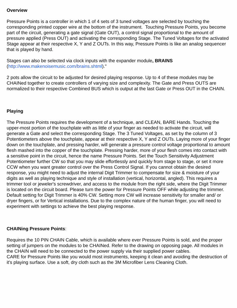
Overview
Pressure Points is a controller in which 1 of 4 sets of 3 tuned voltages are selected by touching the corresponding printed copper wire at the bottom of the instrument. Touching Pressure Points, you become part of the circuit, generating a gate signal (Gate OUT), a control signal proportional to the amount of pressure applied (Press OUT) and activating the corresponding Stage. The Tuned Voltages for the activated Stage appear at their respective X, Y and Z OUTs. In this way, Pressure Points is like an analog sequencer that is played by hand.
Stages can also be selected via clock inputs with the expander module, BRAINS (http://www.makenoisemusic.com/brains.shtml)."
2 pots allow the circuit to be adjusted for desired playing response. Up to 4 of these modules may be CHAINed together to create controllers of varying size and complexity. The Gate and Press OUTS are normalized to their respective Combined BUS which is output at the last Gate or Press OUT in the CHAIN.
Playing
The Pressure Points requires the development of a technique, and CLEAN, BARE Hands. Touching the upper-most portion of the touchplate with as little of your finger as needed to activate the circuit, will generate a Gate and select the corresponding Stage. The 3 Tuned Voltages, as set by the column of 3 Potentiometers above the touchplate, appear at their respective X, Y and Z OUTs. Laying more of your finger down on the touchplate, and pressing harder, will generate a pressure control voltage proportional to amount flesh mashed into the copper of the touchplate. Pressing harder, more of your flesh comes into contact with a sensitive point in the circuit, hence the name Pressure Points. Set the Touch Sensitivity Adjustment Potentiometer further CW so that you may slide effortlessly and quickly from stage to stage, or set it more CCW when you want greater control over the Press Control Signal. If you cannot obtain the desired response, you might need to adjust the internal Digit Trimmer to compensate for size & moisture of your digits as well as playing technique and style of installation (vertical, horizontal, angled). This requires a trimmer tool or jeweler's screwdriver, and access to the module from the right side, where the Digit Trimmer is located on the circuit board. Please turn the power for Pressure Points OFF while adjusting the trimmer. Default setting for Digit Trimmer is 40% CW. Setting more CW will increase sensitivity for smaller and/ or dryer fingers, or for Vertical installations. Due to the complex nature of the human finger, you will need to experiment with settings to achieve the best playing response.
CHAINing Pressure Points:
Requires the 10 PIN CHAIN Cable, which is available where ever Pressure Points is sold, and the proper setting of jumpers on the modules to be CHAINed. Refer to the drawing on opposing page. All modules in the CHAIN will need to be connected to the power supply via their supplied power cables.CARE for Pressure Points like you would most instruments, keeping it clean and avoiding the destruction of it's playing surface. Use a soft, dry cloth such as the 3M Microfiber Lens Cleaning Cloth.
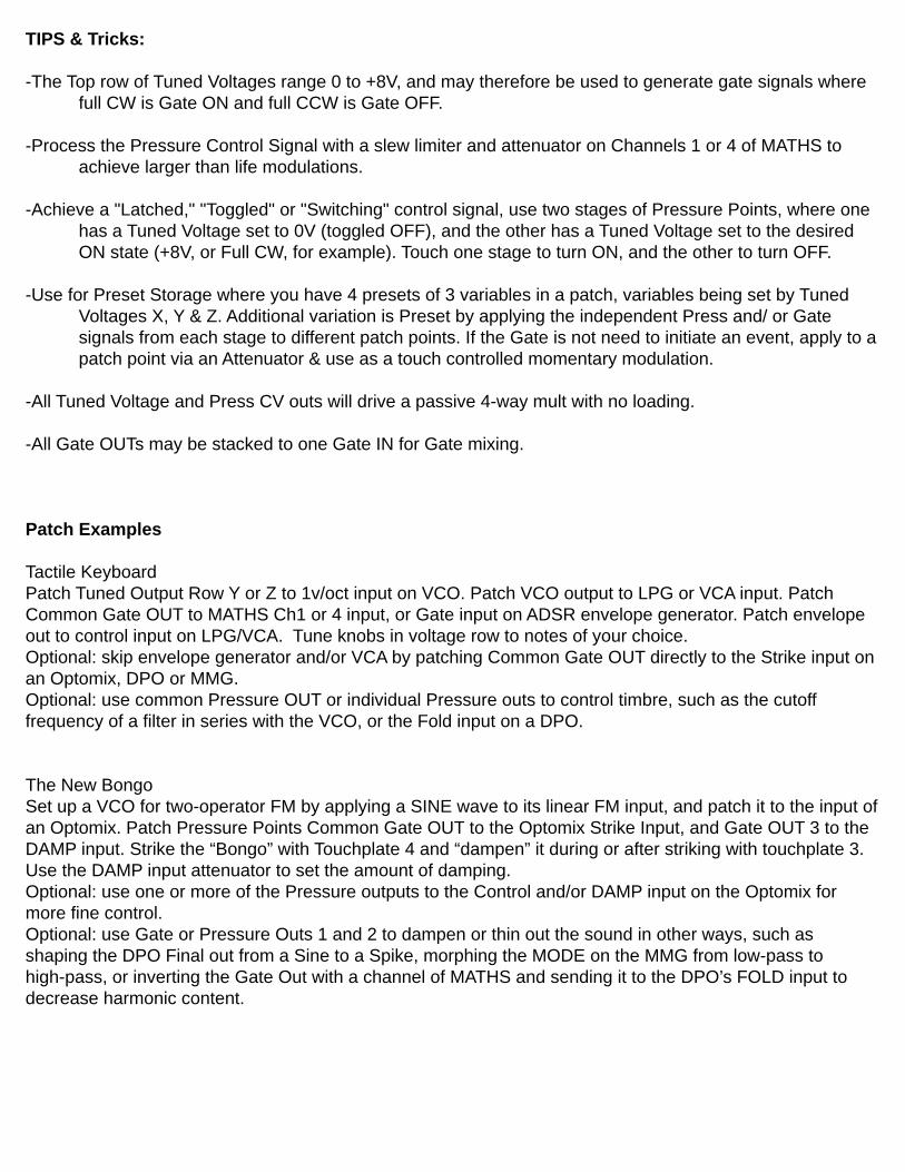
TIPS & Tricks:
-The Top row of Tuned Voltages range 0 to +8V, and may therefore be used to generate gate signals where full CW is Gate ON and full CCW is Gate OFF.
-Process the Pressure Control Signal with a slew limiter and attenuator on Channels 1 or 4 of MATHS to achieve larger than life modulations.
-Achieve a "Latched," "Toggled" or "Switching" control signal, use two stages of Pressure Points, where one has a Tuned Voltage set to 0V (toggled OFF), and the other has a Tuned Voltage set to the desired ON state (+8V, or Full CW, for example). Touch one stage to turn ON, and the other to turn OFF.
-Use for Preset Storage where you have 4 presets of 3 variables in a patch, variables being set by Tuned Voltages X, Y & Z. Additional variation is Preset by applying the independent Press and/ or Gate signals from each stage to different patch points. If the Gate is not need to initiate an event, apply to a patch point via an Attenuator & use as a touch controlled momentary modulation.
-All Tuned Voltage and Press CV outs will drive a passive 4-way mult with no loading.
-All Gate OUTs may be stacked to one Gate IN for Gate mixing.
Patch Examples Tactile KeyboardPatch Tuned Output Row Y or Z to 1v/oct input on VCO. Patch VCO output to LPG or VCA input. Patch Common Gate OUT to MATHS Ch1 or 4 input, or Gate input on ADSR envelope generator. Patch envelope out to control input on LPG/VCA. Tune knobs in voltage row to notes of your choice. Optional: skip envelope generator and/or VCA by patching Common Gate OUT directly to the Strike input on an Optomix, DPO or MMG.Optional: use common Pressure OUT or individual Pressure outs to control timbre, such as the cutoff frequency of a filter in series with the VCO, or the Fold input on a DPO. The New BongoSet up a VCO for two-operator FM by applying a SINE wave to its linear FM input, and patch it to the input of an Optomix. Patch Pressure Points Common Gate OUT to the Optomix Strike Input, and Gate OUT 3 to the DAMP input. Strike the “Bongo” with Touchplate 4 and “dampen” it during or after striking with touchplate 3. Use the DAMP input attenuator to set the amount of damping.Optional: use one or more of the Pressure outputs to the Control and/or DAMP input on the Optomix for more fine control.Optional: use Gate or Pressure Outs 1 and 2 to dampen or thin out the sound in other ways, such as shaping the DPO Final out from a Sine to a Spike, morphing the MODE on the MMG from low-pass to high-pass, or inverting the Gate Out with a channel of MATHS and sending it to the DPO’s FOLD input to decrease harmonic content.


