Pressure Gauges, FLUID COMPONENTS, INC. … · All Dynamic gauges come with a standard...
31
- 4 - FLUID COMPONENTS, INC. *DXJHV Service Filter Gauges ....................................... 5 CDS Series - Dry .............................................. 6-7 &) 6HULHV *O\FHULQH¿OOHG ............................... 8-9 3'/& 6HULHV ´ *O\FHULQH¿OOHG ...................... 10 &)& 6HULHV ´ *O\FHULQH¿OOHG ........................ 11 PDSS Series - All Stainless Steel ..................... 12-13 PDTG Series - Test Gauges ............................. 14 Pressure Gauge Accessories ............................ 15 Pressure Gauges, Valves & Accessories APPENDIX +<'5$8/,& 027256 +<'5$8/,& 38036 *$8*(6 $&&(6625,(6 *HQHUDO ,QIRUPDWLRQ 3UHVVXUH *DXJHV The maximum working pressures of standard gauges should not exceed 75% of full scale for constant pressure applications, or 66% of full scale for pulsating pressures. Normal overpressures allowed are: 1.25 times FSV for ranges up to 1,000 psi; 1.15 times FSV for ranges between 1,000 and 10,000 psi; 1.10 times FSV for higher pressures. Dial face includes both psi (black) and bar (red) scales. PSI only faces may be available. To see standard increments and dial faces, see pages 16-17. *O\FHULQH LV XVHG DV VWDQGDUG LQ PRVW '\QDPLF ÀXLG¿OOHG JDXJHV Neither glycerine nor silicone should be used in applications involving oxygen, chlorine, nitric acid, hydrogen peroxide or other oxidizing agents. All Dynamic gauges come with a standard polycarbonate lens. Safety glass or tempered glass covers are available with PLQLPXP RUGHU '\QDPLF ¿OOHG JDXJHV LQFOXGH D GXDO UHOLHI YDOYHEORZRXW GLVF IRU RSHUDWLQJ VDIHW\ Test Points The need for preventative maintenance of hydraulic systems in general has added to the use of test points throughout the system. This need is answered by the installation of a range of test points, plugs and probes, which can be connected under full system pressure to 6000 psi. Where the introduction of test points is QHHGHG DQG WKH K\GUDXOLF V\VWHP XVHV ÀH[LEOH K\GUDXOLF KRVHV '\QDPLF KDV D UDQJH RI +\GUD7HVW KRVH FRXSOLQJV ¿WWHG ZLWK WHVW SRLQWV )RU IXOO SURGXFW GDWD FRQVXOW SDJHV 9DOYHV )ORZ 'LYLGHUV 1HZ SURGXFWV KDYH EHHQ UHFHQWO\ DGGHG WR '\QDPLF¶V H[WHQVLYH LQYHQWRU\ RI YDOYHV DQG ÀRZ GLYLGHUV LQFOXGLQJ a 6-way, 2-station Selector Valve and a Spool Flow Divider. 7HVW 3RLQW 3OXJV 3UREHV +RVH $VVHPEOLHV Test Point Plugs & Probes ................................ 16-17 Hose Couplings ................................................. 18 Hose Assemblies & End Fittings ....................... 19-20 9DOYHV )ORZ 'LYLGHUV Check Valves .................................................... 21 Ball Valves & Accessories ................................. 22-24 Log Splitter Control Valve ................................. 25 Needle Valves ................................................... 26-27 Flow Control Valves ......................................... 28-29 Flow Dividers .................................................... 30-31 Selector Valve ................................................... 32 5HVHUYRLU $FFHVVRULHV Screw-On Air Breathers .................................... 33 Filter Filler Breathers ......................................... 34 *DXJHV 9DOYHV $FFHVVRULHV TABLE OF CONTENTS
Transcript of Pressure Gauges, FLUID COMPONENTS, INC. … · All Dynamic gauges come with a standard...

- 4 -
APP
END
IXH
YDR
AU
LIC
MO
TOR
SH
YDR
AU
LIC
PU
MPS
GA
UG
ES &
AC
CES
SOR
IES
FLUID COMPONENTS, INC.
Service Filter Gauges ....................................... 5CDS Series - Dry .............................................. 6-7
............................... 8-9 ...................... 10
........................ 11PDSS Series - All Stainless Steel ..................... 12-13PDTG Series - Test Gauges ............................. 14 Pressure Gauge Accessories ............................ 15
Pressure Gauges, Valves & Accessories
APP
END
IX
The maximum working pressures of standard gauges should not exceed 75% of full scale for constant pressure applications, or 66% of full scale for pulsating pressures. Normal overpressures allowed are: 1.25 times FSV for ranges up to 1,000 psi; 1.15 times FSV for ranges between 1,000 and 10,000 psi; 1.10 times FSV for higher pressures. Dial face includes both psi (black) and bar (red) scales. PSI only faces may be available. To see standard increments and dial faces, see pages 16-17.
Neither glycerine nor silicone should be used in applications involving oxygen, chlorine, nitric acid, hydrogen peroxide or other oxidizing agents.
All Dynamic gauges come with a standard polycarbonate lens. Safety glass or tempered glass covers are available with
Test Points
The need for preventative maintenance of hydraulic systems in general has added to the use of test points throughout the system. This need is answered by the installation of a range of test points, plugs and probes, which can be connected under full system pressure to 6000 psi. Where the introduction of test points is
a 6-way, 2-station Selector Valve and a Spool Flow Divider.
Test Point Plugs & Probes ................................ 16-17Hose Couplings ................................................. 18Hose Assemblies & End Fittings ....................... 19-20
Check Valves .................................................... 21 Ball Valves & Accessories ................................. 22-24Log Splitter Control Valve ................................. 25Needle Valves ................................................... 26-27Flow Control Valves ......................................... 28-29Flow Dividers .................................................... 30-31Selector Valve ................................................... 32
Screw-On Air Breathers .................................... 33Filter Filler Breathers ......................................... 34
TABLE OF CONTENTS

- 5 -
APPEN
DIX
1 1/
Service Filter Gauges
Features
1/8” NPT Bronze Connection
Installation DataFeatures
1/8” NPT Bronze Connection
Installation Data
FLUID COMPONENTS, INC.

- 6 -
APP
END
IXH
YDR
AU
LIC
MO
TOR
SH
YDR
AU
LIC
PU
MPS
GA
UG
ES &
AC
CES
SOR
IES
Features
(see page 15 for details)
Installation Data
* 1/8” NPT available w/ min. order. Add -8N to end of model #.
Size A B D Port1 1/2” 1.62” .90” 2.26” 1.50” 1/8” NPT
2” 2.00” 1.08” 2.81” 1.80” 1/4” NPT*
2 1/2” 2.45” 1.05” 3.22” 1.75” 1/4” NPT*
Style DStyle A
CDS Series Dry Gauges1 1/ ” 1/
Size
*4 = 1 1/2” dia. 5 = 2” dia. 1 = 2 1/2” dia.
Style
A = StemD = Center Back
Ordering Example: 1 P DModel Size Type Range Style
Model
CDS = Dry Gauge
Type
C = CompoundV = VacuumP = Pressure
Pressure Range
002 = 30” Hg - 30 psi** 000 = 30” Hg - 0 psi001 = 15 psi002 = 30 psi004 = 60 psi007 = 100 psi010 = 160 psi015 = 200 psi020 = 300 psi040 = 600 psi
070 = 1000 psi100 = 1500 psi140 = 2000 psi210 = 3000 psi280 = 4000 psi350 = 5000 psi420 = 6000 psi * 1 1/2” dia. is limited to 5000 psi
**Additional compound ranges may be available by special order.
Some size/range combinations may
special order.
FLUID COMPONENTS, INC.

- 7 -
APPEN
DIX
Installation Data
Features
(see page 15 for details)
Style EStyle B
Size A B D E F H J Port2” 2.25” .20” 1.75” 2.28” 2.05” 2.45” 2.80” .21” 1.15” 1/4” NPT*
2 1/2” 2.68” .20” 1.75” 3.14” 2.40” 2.85” 3.29” .247” 1.17” 1/4” NPT*
CDS Series Dry Gauges” 1/
Size
5 = 2” dia.1 = 2 1/2” dia.
Style
B = Panel ClampE = Panel Flange
Ordering Example: P EModel Size Type Range Style
Model
CDS = Dry Gauge
Type
C = CompoundV = VacuumP = Pressure
Pressure Range
002 = 30” Hg - 30 psi** 000 = 30” Hg - 0 psi001 = 15 psi002 = 30 psi004 = 60 psi007 = 100 psi010 = 160 psi015 = 200 psi020 = 300 psi040 = 600 psi
070 = 1000 psi100 = 1500 psi140 = 2000 psi210 = 3000 psi280 = 4000 psi350 = 5000 psi420 = 6000 psi
* 1/8” NPT available w/ min. order. Add -8N to end of model #.
**Additional compound ranges may be available by special order.
Some size/range combinations may
special order.
FLUID COMPONENTS, INC.

- 8 -
APP
END
IXH
YDR
AU
LIC
MO
TOR
SH
YDR
AU
LIC
PU
MPS
GA
UG
ES &
AC
CES
SOR
IES
Features
(see page 15 for details)
Installation Data
Size
*4 = 1 1/2” dia. 5 = 2” dia. 1 = 2 1/2” dia.
Style
A = StemB = Panel ClampD = Center BackE = Panel Flange
Size A B D E F H Port Size1 1/2” 1.58” 1.98” 1.02” 2.47” 2.30” - - .20” 1/8” NPT
2” 1.98” 2.21” 1.19” 3.05” 2.28” 2.40” 2.76” .24” 1/4” NPT*
2 1/2” 2.40” 2.25” 1.18” 3.45” 3.18” 2.90” 3.42” .25” 1/4” NPT*
*Note: 1 1/2” dia. is limited to 6000 psi**Additional compound ranges may be available by special order.
CF Series Gauges11/ ” ” 1/
Style EStyle A Style D Style B
Ordering Example: 1 P AModel Size Type Range Style
Model
CF =
Gauge
Type
C = CompoundV = VacuumP = Pressure
Pressure Range
002 = 30” Hg - 30 psi** 000 = 30” Hg - 0 psi001 = 15 psi002 = 30 psi004 = 60 psi007 = 100 psi010 = 160 psi015 = 200 psi020 = 300 psi040 = 600 psi
070 = 1000 psi100 = 1500 psi140 = 2000 psi210 = 3000 psi280 = 4000 psi350 = 5000 psi420 = 6000 psi700 = 10,000 psi
* 1/8” NPT available w/ min. order. Add -8N to end of model #.
Some size/range combinations may only be
FLUID COMPONENTS, INC.

- 9 -
APPEN
DIX
Ordering Example:
Features
Installation Data
Model
CF =
Gauge
Size
1 = 2 1/2”
Type
C = CompoundV = VacuumP = Pressure
Pressure Range
002 = 30” Hg - 30 psi** 000 = 30” Hg - 0 psi001 = 15 psi002 = 30 psi004 = 60 psi007 = 100 psi010 = 160 psi015 = 200 psi020 = 300 psi040 = 600 psi
070 = 1000 psi100 = 1500 psi140 = 2000 psi210 = 3000 psi280 = 4000 psi350 = 5000 psi420 = 6000 psi700 = 10,000 psi
Style
A = StemD = Center Back*
Port Size
7/16-20 SAE
CF Series (SAE) Gauges1/
Style DStyle A
1 P A SAEModel Size Type Range Style Port Size
(see page 15 for details)
*Special order - minimum quantities may apply.*Additional compound ranges may be available by special order.
FLUID COMPONENTS, INC.

- 10 -
APP
END
IXH
YDR
AU
LIC
MO
TOR
SH
YDR
AU
LIC
PU
MPS
GA
UG
ES &
AC
CES
SOR
IES PDLC Series Gauges
Features
1/4” NPT Connection
Installation Data
Style A Style D Style B
Size
2 = 4” dia.
Style
A = StemB = Panel ClampD = Center Back
Ordering Example: P AModel Size Type Range Style
Model
PDLC = Low cost,
4” gauge
Type
P = Pressure
Pressure Range
001 = 15 psi002 = 30 psi004 = 60 psi007 = 100 psi010 = 160 psi015 = 200 psi020 = 300 psi040 = 600 psi
070 = 1000 psi100 = 1500 psi140 = 2000 psi210 = 3000 psi280 = 4000 psi350 = 5000 psi420 = 6000 psi700 = 10,000 psi
(see page 15 for details)
1/4” NPT is standard connection for all PDLC gauges.
FLUID COMPONENTS, INC.

- 11 -
APPEN
DIX
Features
Installation Data
Dimensional Information
*1/4” NPT is standard connection for 600 psi and below; 1/2” NPT is standard for 1000 psi and above
Style A Style B Style E
Style A B D* E F
A - Stem 4.28” 1.82” 3.91” 5.30” (1/4” NPT)5.36” (1/2” NPT) - - -
B - Panel Clamp 4.28” 1.85” 3.91” 3.10” (1/4” NPT)3.20” (1/2” NPT) - - 5.00”
D - Lower Back 4.28” 1.85” 3.91” 3.10” (1/4” NPT)3.20” (1/2” NPT) - - -
E - Panel Flange 4.28” 1.85” 3.91” 3.10” (1/4” NPT)3.20” (1/2” NPT) 5.16” .33” -
CFC Series Gauges
Style D
Size
2 = 4” dia.
Style
A = StemB = Panel ClampD = Lower BackE = Panel Flange
Ordering Example: P AModel Size Type Range Style
Model
CFC =
4” Gauge
Type
C = CompoundV = VacuumP = Pressure
Pressure Range
002 = 30” Hg - 30 psi** 000 = 30” Hg - 0 psi001 = 15 psi002 = 30 psi004 = 60 psi007 = 100 psi010 = 160 psi015 = 200 psi020 = 300 psi040 = 600 psi
070 = 1000 psi100 = 1500 psi140 = 2000 psi210 = 3000 psi280 = 4000 psi350 = 5000 psi420 = 6000 psi700 = 10,000 psi
(see page 15 for details)
**Additional compound ranges may be available by special order.
FLUID COMPONENTS, INC.

- 12 -
APP
END
IXH
YDR
AU
LIC
MO
TOR
SH
YDR
AU
LIC
PU
MPS
GA
UG
ES &
AC
CES
SOR
IES
Features
(see page 15 for details)
Installation Data
Style A Style BStyle D Style E
PDSS Series Gauges1/
Size
1 = 2 1/2” dia.
Style
A = StemB = Panel ClampD = Center BackE = Panel Flange
Ordering Example: PDSS 1 P AModel Size Type Range Style
Model
PDSS = All Stainless Steel Gauges
Type
C = CompoundV = VacuumP = Pressure
Pressure Range
002 = 30” Hg -30 psi** 000 = 30” Hg - 0 psi001 = 15 psi002 = 30 psi004 = 60 psi007 = 100 psi010 = 160 psi015 = 200 psi020 = 300 psi040 = 600 psi070 = 1000 psi
100 = 1500 psi 140 = 2000 psi210 = 3000 psi280 = 4000 psi350 = 5000 psi420 = 6000 psi700 = 10,000 psi800 = 15,000 psi
001Options
Options
002 = Dry*
1/4” NPT is the standard connection for all 2 1/2” PDSS gauges.
* Special Order**Additional compound ranges may be available by special order.
FLUID COMPONENTS, INC.

- 13 -
APPEN
DIX
Features
(see page 15 for details)
Installation Data
Style A Styles B & D Style E
PDSS Series Gauges
Size
2 = 4” dia.3* = 6” dia.
Style
A = StemB = Panel ClampD = Lower BackE = Panel Flange
Ordering Example: PDSS P DModel Size Type Range Style
Model
PDSS = All Stainless Steel Gauges
Type
C = CompoundV = VacuumP = Pressure
Pressure Range
002 = 30” Hg -30 psi** 000 = 30” Hg - 0 psi001 = 15 psi002 = 30 psi004 = 60 psi007 = 100 psi010 = 160 psi015 = 200 psi020 = 300 psi040 = 600 psi070 = 1000 psi
100 = 1500 psi140 = 2000 psi210 = 3000 psi280 = 4000 psi350 = 5000 psi420 = 6000 psi700 = 10,000 psi800 = 15,000 psi900 = 20,000 psi950 = 30,000 psi
001Options
Options
002* = Dry
*1/4” NPT is standard connection for 600 psi and below; 1/2” NPT is standard for 1000 psi and above
* Special Order**Additional compound ranges may be available by special order.
Style A B D* E F
A - Stem 4.28” 1.84” 3.87” 5.30” (1/4” NPT)5.36” (1/2” NPT) - - -
B - Panel Clamp 4.28” 1.87” 3.87” 3.10” (1/4” NPT)3.20” (1/2” NPT) - - 5.00”
D - Lower Back 4.28” 1.87” 3.87” 3.10” (1/4” NPT)3.20” (1/2” NPT) - - -
E - Panel Flange 4.28” 1.87” 3.87” 3.10” (1/4” NPT)3.20” (1/2” NPT) 5.13” .27” -
FLUID COMPONENTS, INC.

- 14 -
APP
END
IXH
YDR
AU
LIC
MO
TOR
SH
YDR
AU
LIC
PU
MPS
GA
UG
ES &
AC
CES
SOR
IES
Features
1/4” NPT Connection
Installation Data
Style A Style B
PDTG Test GaugesAvailable by Special Order Only
Size
3 = 6” dia.
Style
A = StemB = Panel Clamp
Ordering Example: P AModel Size Type Range Style
Model
PDTG = Test Gauges
Type
C = CompoundV = VacuumP = Pressure
Pressure Range
002 = 30” Hg -30 psi** 000 = 30” Hg - 0 psi001 = 15 psi002 = 30 psi004 = 60 psi007 = 100 psi010 = 160 psi015 = 200 psi020 = 300 psi040 = 600 psi070 = 1000 psi
100 = 1500 psi 140 = 2000 psi210 = 3000 psi280 = 4000 psi350 = 5000 psi420 = 6000 psi700 = 10,000 psi800 = 15,000 psi900 = 20,000 psi
01Options
Options
Omit = Standard 01 = Shatterproof Lens
**Additional compound ranges may be available.
FLUID COMPONENTS, INC.
- 15 -
APPEN
DIX
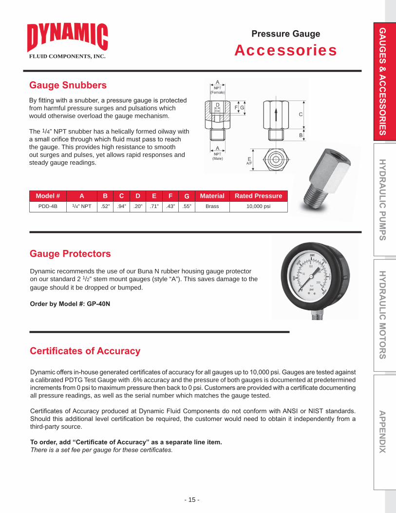
from harmful pressure surges and pulsations which would otherwise overload the gauge mechanism.
The 1/4” NPT snubber has a helically formed oilway with
the gauge. This provides high resistance to smooth out surges and pulses, yet allows rapid responses and steady gauge readings.
Model # A B D E F Material Rated PressurePDD-4B 1/4” NPT .52” .94” .20” .71” .43” .55” Brass 10,000 psi
Dynamic recommends the use of our Buna N rubber housing gauge protector on our standard 2 1/2” stem mount gauges (style “A”). This saves damage to the gauge should it be dropped or bumped.
Accessories
a calibrated PDTG Test Gauge with .6% accuracy and the pressure of both gauges is documented at predetermined
all pressure readings, as well as the serial number which matches the gauge tested.
third-party source.
FLUID COMPONENTS, INC.

- 16 -
APP
END
IXH
YDR
AU
LIC
MO
TOR
SH
YDR
AU
LIC
PU
MPS
GA
UG
ES &
AC
CES
SOR
IES
Model # Form Max. Pressure JD1620-01-18NPT C 5800 psi .67” .37” 1/8” NPTD1620-01-14NPT C 9000 psi .67” .55” 1/4” NPTD1620-01-04SAE F 9000 psi .67” .43” 04-SAED1620-01-06SAE F 9000 psi .75” .47” 06-SAED1620-01-08SAE F 9000 psi .87” .55” 08-SAED1620-01-M10X1 E 9000 psi .67” .33” M10X1D1620-01-M12x1.5 E 9000 psi .67” .47” M12x1.5D1620-01-M14x1.5 E 9000 psi .75” .47” M14x1.5D1620-01-M16x1.5 E 9000 psi .87” .47” M16x1.5D1620-01-18BSPP E 9000 psi .67” .32” 1/8” BSPPD1620-01-14BSPP E 9000 psi .75” .47” 1/4” BSPPD1620-01-38BSPP E 9000 psi .87” .47” 3/8” BSPP
Features
Form C Form E Form F
DGA1620 Test Point Probes are designed to connect directly to the D1620 Test Point
released into the gauge’s bourdon tube as the probe opens the test point valve. It can be connected and disconnected under pressure. This provides a precise means to monitor system pressure without turning the system off.
Dynamic recommends the use of a gauge protector Buna N rubber housing when using a test point probe. This saves damage to the gauge should it be dropped or bumped during the test proceedings. Gauge Protectors can be ordered using model #: GP-40N. See page 15.
*Test Point Probe does not include gauge.
Test Point Plugs
Test Point Probe
FLUID COMPONENTS, INC.

- 17 -
APPEN
DIX
Features
Model #’s and Dimensional Information
*Special Order Only
Dynamic test point plugs and probes are designed to monitor hydraulic system conditions without system
application where eventual system monitoring is required.
Model # AThread B D E Max. Torque Weight Seal Kits
FTP-02N 1/8” NPT .39” 1.81” -- .75” 180 lbs .15 lbsFTP-04N 1/4” NPT .56” 1.87” -- .82” 180 lbs .17 lbsFTP-04S 7/16-20 SAE .36” 1.81” .71” .75” 180 lbs .17 lbs
FTP Series
Test Point Plugs
FPP Series
Test Point ProbeFPP Test Point Probes are designed to connect directly to the FTP Test Point Plugs
into the gauge’s bourdon tube as the probe opens the test point valve. It can be connected and disconnected under pressure. This provides a precise means to monitor system pressure without turning the system off.
1/2”, 0-3000 psi
stem mount gauge). See page 8 for 2 1/2” pressure gauge data.
Dynamic recommends the use of a gauge protector Buna N rubber housing when using a test point probe. This saves damage to the gauge should it be dropped or bumped during the test proceedings. Gauge Protectors can be ordered using model #: GP-40N. See page 15.
FLUID COMPONENTS, INC.

- 18 -
APP
END
IXH
YDR
AU
LIC
MO
TOR
SH
YDR
AU
LIC
PU
MPS
GA
UG
ES &
AC
CES
SOR
IES
Model # A B D E F WeightSeal Kit
Nitrile* Viton*
HSP1040-4 7/16”-20 UNF 2.01” 1.00” 1.22” .56” 1.12” .29 lbs
HSP1040-5 1/2”-20 UNF 2.01” 1.00” 1.30” .62” 1.12” .31 lbs
HSP1040-6 9/16”-20 UNF 2.01” 1.01” 1.36” .69” 1.12” .33 lbs
HSP1040-8 3/4”-16 UNF 2.01” 1.11” 1.33” .87” 1.12” .35 lbs
HSP1040-10 7/8”-14 UNF 2.14” 1.23” 1.51” 1.00” 1.37” .55 lbs
HSP1040-12 11/16”-12 UNF 2.14” 1.31” 1.64” 1.25” 1.37” .66 lbs
HSP1040-16 15/16”-12 UNF 2.30” 1.36” 1.72” 1.50” 1.69” .95 lbs
HSP1040-20 15/8”-12 UNF 2.61” 0.96” 1.77” 2.05” 2.00” 1.71 lbs
HSP1040-24 17/8”-12 UNF 2.98” 1.08” 1.89” 2.20” 2.22” 1.98 lbs
Features
*Special Order Only
Hose Couplings
Model #’s and Dimensional Information
FLUID COMPONENTS, INC.

- 19 -
APPEN
DIX
Test Plugs, Pipe Couplings and Standpipe adaptors. Together they facilitate pressure readings on a random basis throughout a hydraulic system. Probes may be connected or disconnected with the system at full working pressure without loss of oil or ingress of dirt. Use of test points saves the installation of multiple pipework and gauges.
Please specify in inches if other lengths are required. Minimum length is 12”.
Note: If you require a gauge assembled to the hose assembly, please add the gauge number to the end of the part number.
Hose Lengths12” 24” 36”48” 60” 72”
Ordering Example: DHA FTPModel End Fitting Length
End Fitting
See codes on next page
End Fitting
Model
DHA = Dynamic Hose Assembly
Hose Length
Length in inches(see Table 1)
End Fitting
See codes on next page
Table 1
Hose AssembliesFLUID COMPONENTS, INC.

- 20 -
APP
END
IXH
YDR
AU
LIC
MO
TOR
SH
YDR
AU
LIC
PU
MPS
GA
UG
ES &
AC
CES
SOR
IES
End FittingsFLUID COMPONENTS, INC.

- 21 -
APPEN
DIX
Model # Thread Size A BRated Flow (gpm)
Rated Pressure
(psi)
Weight(lbs)
VU14F-7 or 70 1/4” NPT 2.83” .87” 10.6 10,000 .35
VU38F-7 or 70 3/8” NPT 3.30” 1.03” 13.2 10,000 .44
VU12F-7 or 70 1/2” NPT 3.78” 1.18” 18.5 7,250 .77
VU34F-7 or 70 3/4” NPT 4.28” 1.50” 26.4 7,250 1.54
VU1F-7 or 70 1” NPT 4.96” 1.81” 39.6 7,250 2.43
VU114F-7 or 70 1 1/4” NPT 5.12” 2.17” 52.8 4,350 6.95
VU112F-7 or 70 1 1/2” NPT 5.31” 2.56” 66.0 4,350 7.28
VU2F-7 or 70 2” NPT 5.91” 2.95” 79.3 4,350 9.52
Model # Thread Size A BRatedFlow (gpm)
RatedPressure
(psi)
Weight(lbs)
HSP-1000-2-5 or 65 1/4” NPT 2.44” .87” 6 5000 .35HSP-1000-3-5 or 65 3/8” NPT 2.87” 1.00” 10 5000 .44HSP-1000-4-5 or 65 1/2” NPT 3.76” 1.26” 18 5000 .77
HSP-1000-6-5 or 65 3/4” NPT 4.30” 1.50” 30 5000 1.54
HSP-1000-8-5 or 65 1” NPT 5.12” 1.69” 36 5000 2.43
HSP-1000-10-5 or 65 1 1/4” NPT 5.56” 2.40” 50 3000 6.95
HSP-1000-12-5 or 65 1 1/2” NPT 5.56” 2.56” 60 3000 7.28
HSP-1001-4-5 or 65 7/16”-20 SAE 2.56” .87” 6 5000 .35
HSP-1001-6-5 or 65 9/16”-20 SAE 2.91” .94” 10 5000 .44
HSP-1001-8-5 or 65 3/4”-16 SAE 3.74” 1.18” 18 5000 .77
HSP-1001-12-5 or 65 1 1/16”-12 SAE 4.29” 1.50” 30 3000 1.54
HSP-1001-16-5 or 65 1 5/16”-12 SAE 5.00” 1.81” 36 3000 2.43
HSP-1001-20-5 or 65 1 5/8”-12 SAE 5.20” 2.41” 50 3000 6.95
HSP-1001-24-5 or 65 1 7/8”-12 SAE 5.20” 2.56” 60 3000 7.28
Check Valves
Features
Features
FLUID COMPONENTS, INC.

- 22 -
APP
END
IXH
YDR
AU
LIC
MO
TOR
SH
YDR
AU
LIC
PU
MPS
GA
UG
ES &
AC
CES
SOR
IES
All dimensions in inches.
Features
1/4” - 2” Sizes - NPT and SAE
Model # Thread psi Port A B D E F H J K SW WeightDE2-04-SAE 7/16”-20 7250 .24 1.27 2.71 1.45 .37 1.75 1.10 4.51 .18 1.03 1.05 .32 1.0 lb
DE2-06-SAE 9/16”-18 7250 .39 1.58 2.84 1.65 .41 2.08 1.27 4.51 .26 1.24 1.38 .32 1.5 lb
DE2-08-SAE 3/4”-16 7250 .51 1.58 3.27 1.90 .41 2.08 1.39 4.51 .26 1.46 1.38 .32 1.5 lb
DE2-12-SAE 11/16”-12 5800 .79 2.25 3.74 2.36 .55 2.97 1.90 6.38 .26 1.76 1.99 .39 3.5 lb
DE2-16-SAE 15/16”-12 5000 .98 2.53 4.45 2.56 .55 3.25 2.25 6.38 .26 2.17 2.29 .39 5.0 lb
DE2-20R-SAEReduced Port 15/8”-12 5000 .98 2.53 4.73 2.56 .55 3.25 2.37 6.38 .26 2.17 2.29 .39 5.5 lb
DE2-24R-SAEReduced Port 17/8”-12 5000 .98 2.53 4.85 2.56 .55 3.25 2.37 6.38 .26 2.17 2.29 .39 6.0 lb
DB2-20-SAE 15/8”-12 5000 1.26 3.43 4.72 3.31 .63 4.26 3.22 9.00 - - - .51 9.0 lb
DB2-24-SAE 17/8”-12 5000 1.57 3.92 5.13 3.58 .63 5.01 3.66 9.00 - - - .51 11.5 lb
DB2-32-SAE 21/2”-12 5000 1.97 4.52 5.52 3.94 .63 5.33 4.31 9.00 - - - .51 15.5 lb
Model # Thread psi Port A B D E F H J K SW WeightDE2-14NPT 1/4” NPT 7250 .24 1.27 2.71 1.45 .37 1.75 1.10 4.51 .18 1.03 1.05 .32 1.0 lb
DE2-38NPT 3/8” NPT 7250 .39 1.58 2.84 1.65 .41 2.08 1.27 4.51 .26 1.24 1.38 .32 1.5 lb
DE2-12NPT 1/2” NPT 7250 .51 1.58 3.27 1.90 .41 2.08 1.39 4.51 .26 1.46 1.38 .32 1.5 lb
DE2-34NPT 3/4” NPT 5800 .79 2.25 3.74 2.36 .55 2.97 1.90 6.38 .26 1.76 1.99 .39 3.5 lb
DE2-1-NPT 1” NPT 5000 .98 2.53 4.45 2.56 .55 3.25 2.25 6.38 .26 2.17 2.29 .39 5.0 lb
DE2-114R-NPTReduced Port 11/4” NPT 5000 .98 2.53 4.73 2.56 .55 3.25 2.37 6.38 .26 2.17 2.29 .39 5.5 lb
DE2-112R-NPTReduced Port 11/2” NPT 5000 .98 2.53 4.85 2.56 .55 3.25 2.37 6.38 .26 2.17 2.29 .39 6.0 lb
DB2-114-NPT 11/4” NPT 5000 1.26 3.43 4.72 3.31 .63 4.26 3.22 9.00 - - - .51 9.0 lb
DB2-112-NPT 11/2” NPT 5000 1.57 3.92 5.13 3.58 .63 5.01 3.66 9.00 - - - .51 11.5 lb
DB2-2-NPT 2” NPT 5000 1.97 4.52 5.52 3.94 .63 5.33 4.31 9.00 - - - .51 15.5 lb
2-way Ball Valves
Other Seals by Special Order
DE Model
DB Model
FLUID COMPONENTS, INC.

- 23 -
APPEN
DIX
3-way Ball Valves
Features
Model # Thread psi Port A B D E F H J K SW WeightDE3L-04 SAE 7/16”-20 5880 .24 1.27 2.72 1.46 .38 1.78 1.11 4.51 .18 1.02 1.07 .32 1.0 lb
DE3L-06 SAE 9/16”-18 5880 .39 1.58 2.84 1.65 .38 2.08 1.26 4.51 .26 1.23 1.38 .32 1.5 lbs
DE3L-08 SAE 3/4”-16 5145 .51 1.58 2.28 1.90 .38 2.08 1.37 4.51 .26 1.46 1.38 .32 2.0 lbs
DE3L-12 SAE 11/16”-12 5145 .79 2.27 3.74 2.36 .55 2.97 1.89 6.38 .26 1.77 2.01 .39 4.0 lbs
DE3L-16 SAE 15/16”-12 5145 .98 2.52 4.45 2.56 .55 3.25 2.24 6.38 .26 2.17 2.27 .39 5.5 lbs
DE3L-20R SAEReduced Port 15/8”-12 4500 .98 2.53 4.72 2.56 .55 3.25 2.36 6.38 .26 2.17 2.29 .39 6.0 lbs
DE3L-24R SAEReduced Port 17/8”-12 4500 .98 2.53 4.84 2.56 .55 3.25 2.36 6.38 .26 2.17 2.29 .39 6.5 lbs
DB3L-20 SAE 15/8”-12 4500 1.26 3.31 4.73 3.31 .67 4.14 2.96 9.00 - - - .51 10.5 lbs
DB3L-24 SAE 17/8”-12 4500 1.57 3.74 5.14 3.59 .67 4.61 3.35 9.00 - - - .51 14.0 lbs
DB3L-32 SAE 21/2”-12 4500 1.97 4.43 5.51 3.94 .67 5.18 4.14 9.00 - - - .51 20.0 lbs
Model # Thread psi Port A B D E F H J K SW WeightDE3L-14-NPT 1/4” NPT 5880 .24 1.27 2.72 1.46 .38 1.78 1.11 4.51 .18 1.02 1.07 .32 1.0 lb
DE3L-38-NPT 3/8” NPT 5880 .39 1.58 2.84 1.65 .38 2.08 1.26 4.51 .26 1.23 1.38 .32 1.5 lbs
DE3L-12-NPT 1/2” NPT 5145 .51 1.58 2.28 1.90 .38 2.08 1.37 4.51 .26 1.46 1.38 .32 2.0 lbs
DE3L-34-NPT 3/4” NPT 5145 .79 2.27 3.74 2.36 .55 2.97 1.89 6.38 .26 1.77 2.01 .39 4.0 lbs
DE3L-1-NPT 1” NPT 5145 .98 2.52 4.45 2.56 .55 3.25 2.24 6.38 .26 2.17 2.27 .39 5.5 lbs
DE3L-114R-NPTReduced Port 11/4” NPT 4500 .98 2.53 4.72 2.56 .55 3.25 2.36 6.38 .26 2.17 2.29 .39 6.0 lbs
DE3L-112R-NPTReduced Port 11/2” NPT 4500 .98 2.53 4.84 2.56 .55 3.25 2.36 6.38 .26 2.17 2.29 .39 6.5 lbs
DB3L-114-NPT 11/4” NPT 4500 1.26 3.31 4.73 3.31 .67 4.14 2.96 9.00 - - - .51 10.5 lbs
DB3L-112-NPT 11/2” NPT 4500 1.57 3.74 5.14 3.59 .67 4.61 3.35 9.00 - - - .51 14.0 lbs
DB3L-2-NPT 2” NPT 4500 1.97 4.43 5.51 3.94 .67 5.18 4.14 9.00 - - - .51 20.0 lbs
other seals by special order
FLUID COMPONENTS, INC.

- 24 -
APP
END
IXH
YDR
AU
LIC
MO
TOR
SH
YDR
AU
LIC
PU
MPS
GA
UG
ES &
AC
CES
SOR
IES
Accessories
Model # Description
1/4” - 1/2” Full Port Sizes
3/4” - 1” Full Ports & 1 1/4” -1 1/2” Reduced Ports
11/4” - 2” Full Ports Sizes
1/4” - 1/2” Full Port Sizes
3/4” - 1” Full Ports & 1 1/4” -1 1/2” Reduced Ports
11/4” - 2” Full Port Sizes
Model # Description Length
DE 1/4” - 1/2” Silver Handle Silver Handle for DE2 / DE31/4” - 1/2” Full Port Sizes 4.51”
DE 3/4”-1” Silver HandleSilver Handle for DE2 / DE3
3/4” - 1” Full Port Sizes &1 1/4” -1 1/2” Reduced Ports
6.38”
DB 1 1/4”-2” Silver Handle Silver Handle for DB2 / DB311/4” - 2” Full Port Sizes 9.00”
Not sure how to install your locking kit?
short video demonstration on installing our “U” style locking kits.
“U” Style
Flat Style
FLUID COMPONENTS, INC.

- 25 -
APPEN
DIX
Log Splitter Control Valve
Installation Data
position with no load on the pump, keeping wear and tear on the pump to a minimum.
In exposed applications, do not mount with spool vertical and handle down.
Note: 1/2” NPT ports are standard. Additional port options may be available with special order.
1/2” NPT
Ordering Example: JPLSModel Series
FLUID COMPONENTS, INC.
- 26 -
APP
END
IXH
YDR
AU
LIC
MO
TOR
SH
YDR
AU
LIC
PU
MPS
GA
UG
ES &
AC
CES
SOR
IES
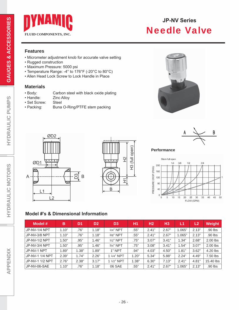
Needle Valve
Materials
Features
Model # B D1 H1 L1 Weight1.10” .76” 1.18” 1/4” NPT .55” 2.41” 2.67” 1.065” 2.13” .90 lbs1.10” .76” 1.18” 3/8” NPT .55” 2.41” 2.67” 1.065” 2.13” .90 lbs1.50” .95” 1.46” 1/2” NPT .75” 3.07” 3.41” 1.34” 2.68” 2.00 lbs1.50” .95” 1.46” 3/4” NPT .75” 3.08” 3.41” 1.54” 3.07” 2.00 lbs1.89” 1.38” 1.89” 1” NPT .94” 4.03” 4.50” 1.81” 3.62” 4.20 lbs2.39” 1.74” 2.26” 1 1/4” NPT 1.20” 5.34” 5.88” 2.24” 4.49” 7.50 lbs2.76” 2.38” 3.17” 1 1/2” NPT 1.38” 6.30” 7.13” 2.41” 4.81” 15.40 lbs1.10” .76” 1.18” 06 SAE .55” 2.41” 2.67” 1.065” 2.13” .90 lbs
Performance
FLUID COMPONENTS, INC.

- 27 -
APPEN
DIX
Model # BodyMaterial
AFemale
BMax.
D E FSquare
HDia. Dia.
DFFG2001T
Carbon Steel
1/8” NPT 3 1/2” 31/32” 1 15/16” 2 1/2” 7/8” 3/8” 5/8” 7/22”
DFFG2002T 1/4” NPT 3 1/2” 1 1/32” 2 1/16” 2 1/2” 7/8” 3/8” 5/8” 7/22”
DFFG2003T 3/8” NPT 3 5/8” 1 7/16” 2 3/4” 2 1/2” 1 1/8” 3/8” 3/4” 7/22”
DFFG2004T 1/2” NPT 3 5/8” 1 7/16” 2 3/4” 2 1/2” 1 1/8” 3/8” 3/4” 7/22”
DFFG2006TA 3/4” NPT 5 3/16” 1 13/16” 3 5/8” 4 1/4” 1 1/2” 7/8” 1 1/2” 9/16”
DFFG2008TA 1” NPT 5 5/16” 2 1/32” 4 1/16” 4 1/4” 2” 7/8” 1 1/2” 9/16”
Needle Valve
Features
FLUID COMPONENTS, INC.

- 28 -
APP
END
IXH
YDR
AU
LIC
MO
TOR
SH
YDR
AU
LIC
PU
MPS
GA
UG
ES &
AC
CES
SOR
IES
Flow Control Valve
Model # B D1 H1 L1 Weight1.10” .76” 1.18” 1/4” NPT .55” 2.41” 2.67” 1.54” 2.52” .90 lbs1.10” .76” 1.18” 3/8” NPT .55” 2.41” 2.67” 1.69” 2.75” .90 lbs1.50” .95” 1.46” 1/2” NPT .75” 3.07” 3.41” 2.05” 3.27” 2.00 lbs1.50” .95” 1.46” 3/4” NPT .75” 3.08” 3.41” 2.19” 3.50” 2.00 lbs1.89” 1.38” 1.89” 1” NPT .94” 4.03” 4.50” 2.79” 4.60” 4.20 lbs2.38” 1.96” 2.28” 11/4” NPT 1.18” 5.25” 5.88” 3.39” 6.07” 9.55 lbs1.10” .76” 1.18” 06 SAE .55” 2.41” 2.67” 1.69” 2.75” .90 lbs1.50” .95” 1.46” 08 SAE .75” 3.07” 3.41” 2.05” 3.27” 2.00 lbs
Materials
Features
Performance
FLUID COMPONENTS, INC.

- 29 -
APPEN
DIX
Flow Control
Materials
Ordering Example: RModel Relief
Model
DFC 38-N = 3/8” NPT (0-8 gpm)12-N = 1/2” NPT (0-16 gpm)34-N = 3/4” NPT (0-30 gpm)06-S = 06 SAE (0-8 gpm)08-S = 08 SAE (0-16 gpm)10-S = 10 SAE (0-16 gpm)12-S = 12 SAE (0-32 gpm)
Installation Data
PortsSeries
Relief Option
N = No Relief
Series
51
FLUID COMPONENTS, INC.

- 30 -
APP
END
IXH
YDR
AU
LIC
MO
TOR
SH
YDR
AU
LIC
PU
MPS
GA
UG
ES &
AC
CES
SOR
IES
FLUID COMPONENTS, INC.
Flow Rate (gpm) = Displacement (in3
from .129 to .517 in3/rev (2.13 to 8.42 cm3
rates of 2.5 to 8.5 gpm are available across the displacement range. Standard ports are SAE, sizes are noted in the data chart below.
ModelDisplacement Min. Flow
each section(gpm)
Max. Flow each section
(gpm)
Max. Outlet Pressure SAE Ports
in cm psi Bar Inlet Outlet
FDA-2-*-129-* .129 2.13 1.20 2.5
3500 240
SAE 8 SAE 8FDA-2-*-194-* .194 3.18 1.70 4.5 SAE 8 SAE 6FDA-2-*-258-* .258 4.24 2.50 5.0 SAE 10 SAE 10FDA-2-*-323-* .323 5.29 3.00 6.0 SAE 10 SAE 10FDA-2-*-388-* .388 6.36 3.50 7.0 SAE 10 SAE 10FDA-2-*-517-* .517 8.42 4.50 9.0 SAE 10 SAE 10FDA-4-*-129-* .129 2.13 1.20 2.0
3500 240
SAE 8 SAE 8FDA-4-*-194-* .194 3.18 1.70 3.0 SAE 8 SAE 6FDA-4-*-258-* .258 4.24 2.50 4.2 SAE 10 SAE 6FDA-4-*-323-* .323 5.29 3.00 4.7 SAE 10 SAE 8FDA-4-*-388-* .388 6.36 3.50 6.1 SAE 10 SAE 8FDA-4-*-517-* .517 8.42 4.50 8.5 SAE 10 SAE 10
Model FDA
Gear Flow Divider
Installation Data
Recommended working conditions:
FILTRATION: 25 micron or better OIL VISCOSITY: 6 - 200 cSt INLET PRESSURE: 12 - 32 psi absolute
FDA = Flow Divider
Series
2 - 2-section 4* - 4-section
Relief
R = Relief Valve N = No Relief Valve
Ports
S - SAE
Ordering Example: FDA RModel Sections Relief Displacement
SPorts
Displacement
129/194/258 323/388/517
*Special Order - minimums may apply

- 31 -
APPEN
DIX
FLUID COMPONENTS, INC.
Port SizeMin. Flow
each section(gpm)
Max. Flow each section
(gpm)
Max. Outlet Pressure
(psi)1/2” NPT 2 8
30003/8” NPT 8 163/4” NPT 16 30#10 SAE 8 16#12 SAE 16 30
Model DYFB
Spool Flow Divider
Installation Data
DYFB = Flow Divider
Flow Options
50 = Inlet to Outlet 100 = Free Reverse Flow
Ordering Example: DYFB 100Model Flow Options Port Size
Port Size
3/8* = 3/8” NPT 1/2 = 1/2” NPT 3/4* = 3/4” NPT 10SAE* = 10 SAE 12SAE* = 12 SAE
Materials
Features
*Special Order - minimums may apply

- 32 -
APP
END
IXH
YDR
AU
LIC
MO
TOR
SH
YDR
AU
LIC
PU
MPS
GA
UG
ES &
AC
CES
SOR
IES
Spool Function
Model DSV
Selector Valve
HydraulicPort Size 3/4-16 - 08 SAE
Max Flow Rate 13.2 gpm
Operating Pressure 3600 psi
Oil Temp Range
Viscosity Range 70-1790 SSu
Filtration Requirement NAS 1638 8
Weight 10 lbs
ElectricalSupply Voltage 12/24VDC
Amperage Rating 1.25 A for DC 24V 2.5A for DC 12V
Max Ambient Temp
Max Coil Temp
Duty Cycle Continuous
Pressure Drop
The Dynamic DSV 12-volt DC selector valve is operated by a continuously rated wet pin solenoid. This is capable of switching from one circuit to another at a
two separate devices. If more than two circuits are to be controlled then additional units can be stacked together (maximum of 3), minimizing the need for pipes and
Style
62 = 6-way, 2-Station
Ordering Example: DSVModel Style Port Size Supply Voltage
Model
DSV= Dynamic Selector Valve
Port Size**
08 = SAE-08
Pressure Range
12 = 12/24VDC
** Additional port sizes may be available by special order.
FLUID COMPONENTS, INC.

- 33 -
APPEN
DIX
Features
1/4” to 1” NPT
Model # Thread A B D Micron Flow
DB40-04 1/4” NPT 1.85” 1.30” .47” .28” .75” 40 40 gpm
DB40-06 3/8” NPT 1.85” 1.30” .47” .28” .75” 40 79 gpm
DB40-08 1/2” NPT 3.12” 2.09” .62” .28” 1.27” 40 119 gpm
DB40-12 3/4” NPT 3.12” 2.09” .62” .28” 1.27” 40 198 gpm
DB40-16 1” NPT 3.12” 2.12” .75” .38” 1.42” 40 225 gpm
Dimensional Information
DB Series
Screw-On Air Breathers
Filtration
40 = 40 micron
Ordering Example: DBModel Filtration
Model
DB = Designation for Breathers
04 = 1/4” NPT 06 = 3/8” NPT 08 = 1/2” NPT 12 = 3/4” NPT 16 = 1” NPT
FLUID COMPONENTS, INC.

- 34 -
APP
END
IXH
YDR
AU
LIC
MO
TOR
SH
YDR
AU
LIC
PU
MPS
GA
UG
ES &
AC
CES
SOR
IES
Features
* Special order
Consult Factory for ordering caps or baskets only
DFB Series
Filter Filler Breathers
Model # D1 H1 Micron Flow Rate
DFB40-03 3.15” 1.97” 3.27” M5 2.05” 2.87” 2.24” 3.07” 40 119 gpm
DFB40-04* 3.15” 1.97” 3.27” M5 2.05” 2.87” 2.24” 3.94” 40 119 gpm
DFB40-06* 3.15” 1.97” 3.27” M5 2.05” 2.87” 2.24” 5.83” 40 119 gpm
Dimensional Information
Filtration
40 = 40 micron
Ordering Example: DFBModel Filtration Basket Length
Model
DFB = Designation for Filter Breathers
Basket Length
03 = 3” 04* = 4” 06* = 6”
MBOptions
Options
MB = Standard Metal Basket L = Lockable
Installation Data
FLUID COMPONENTS, INC.


![Pressure Gauges, Industrial and Process, PGI Series · PDF filePressure Gauges Industrial and Process PGI Series ... K = Safety glass N = Orifice (0.023 in. [0.58 mm]) Available for](https://static.fdocuments.in/doc/165x107/5a78b7997f8b9ae6228bf3c6/pressure-gauges-industrial-and-process-pgi-series-gauges-industrial-and-process.jpg)