Pressure Distribution Guidance - Mass.Gov · Pressure Distribution Guidance ... Step 1: Lay Out a...
56
Pressure Distribution Guidance MassDEP/MHOA Seminar DATE SPEAKER Department of Environmental Protection
Transcript of Pressure Distribution Guidance - Mass.Gov · Pressure Distribution Guidance ... Step 1: Lay Out a...

Pressure Distribution Guidance
MassDEP/MHOA Seminar
DATE
SPEAKER
Department of Environmental Protection

Pressure Distribution Guidance
Updated Guidance published in May 2002
Originally issued in 1995
Developed by committee of health agents, private consultants, equipment suppliers and MassDEP staff
Reflects experience gained since 1995

Pressure Distribution
Promotes uniform distribution throughout the SAS
Uniform distribution promotes proper treatment
Effectiveness depends upon:
Proper design
Proper construction
Proper maintenance
Regulatory Considerations 310 CMR 15.254
Example 1:
A single system serving a single facility is designed for a flow of 2,001 gpd.
Is pressure distribution required?
YES!
Regulatory Considerations 310 CMR 15.254
Example 2:
A single facility with a series of seven systems each with a design flow of 330 gpd.
Is pressure distribution required?
YES!
WHY?
The aggregate flow from the facility is greater than 2,000 gpd (total flow = 2,310 gpd).

Exception to the Regulatory Considerations
Patented Sand Filter Systems* Standard Conditions for Alternative Soil Absorption
Systems with General Use Certification and/or Approved for Remedial Use, February 3,2016
II. Design and Installation Requirements, Paragraph 10, states Specific Conditions for Treatment with Disposal Alt. SAS Technologies
* If the applicant requests LUA for percolation testing (sieve analysis), use of a patented sand filter is not permitted if the soils are compacted or are Class III or Class IV – see MassDEP’s May 3, 2006 Title 5 Alternative to Percolation Testing Guidance for System Upgrades

What Happened in 2002?
2002 1995
1/8” minimum perforation ¼” minimum perforations
Perforations orientated up or down with shield
Perforations at 5 and 7 o’clock – no shields
Lateral cleanouts (recommended)
Lateral cleanouts not mentioned
Greater number of diagrams and design samples
Minimum number of diagrams and design samples

Design Considerations
In-line pressure:
2.5 feet of head at distal lateral
Maximum 10% flow variation in system
Perforations:
1/8” minimum
Uniformly spaced – as many as practical
Stagger in bed formation
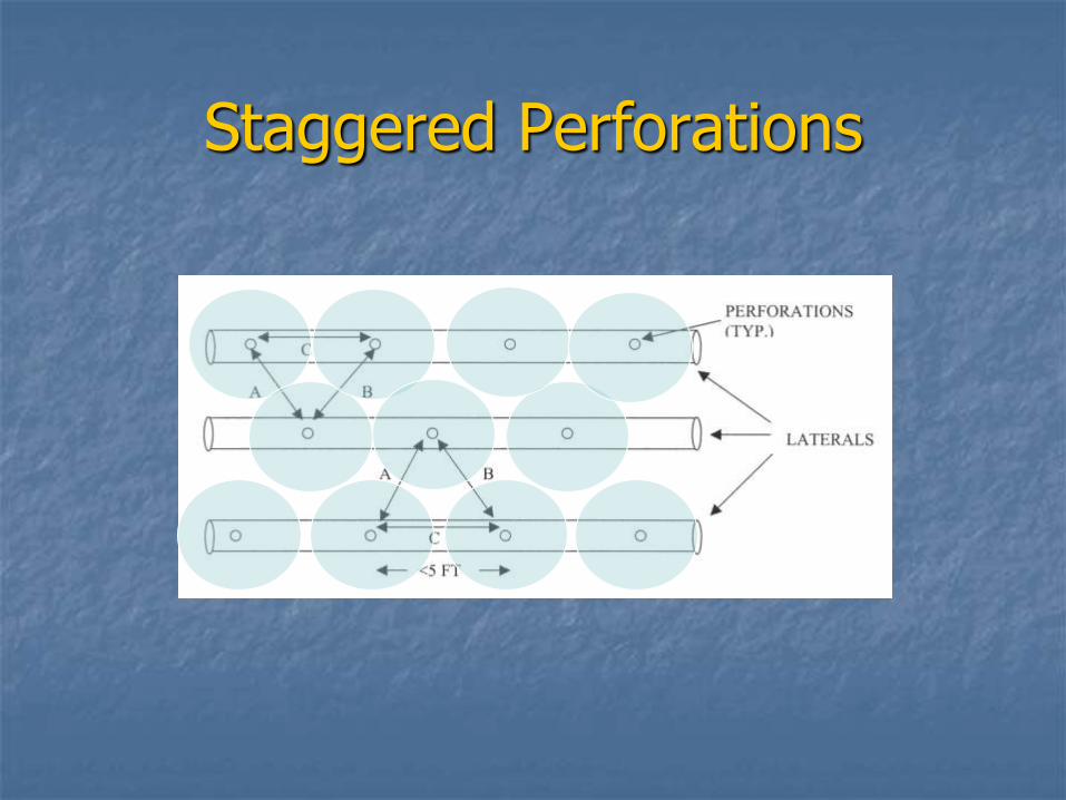
Staggered Perforations

Manifolds
Central or end configuration
Minimize volume
Install below distribution laterals

Center Manifold

Side Manifold

DESIGN PROCEDURES

Step 1: Lay Out a Network
Design is based on site condition, flow rate and soil conditions
Trench or bed configuration
Central or end manifold – central minimizes lateral length
Provide drainage of laterals
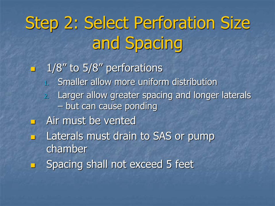
Step 2: Select Perforation Size and Spacing
1/8” to 5/8” perforations
1. Smaller allow more uniform distribution
2. Larger allow greater spacing and longer laterals – but can cause ponding
Air must be vented
Laterals must drain to SAS or pump chamber
Spacing shall not exceed 5 feet

Step 2 – Continued perforation orientation
Between 10 and 2 o’clock or 5 and 7 o’clock
At 12 o’clock or 6 o’clock
Shields are required for between 10 and 2 or at 6 to reduce scouring
Shields can be half pipe, manufactured orifice shields, chambers, etc.

Shields

Detail of Pressure Distribution with Shields

Step 3: Determine lateral pipe diameter
Figures 8A – 8G in Appendix B of Guidance – R. Otis based on Hazen-Williams Equation
Based on C = 150
Perforation size and number
Spacing
Lateral length
Accounts for maximum 10% head loss

Hazen-Williams Equation
h = 0.2083 (100 / c)1.852 q1.852 / dh4.8655
where
h = friction head loss in feet of water per 100 feet of pipe (ftH2O/100 ft pipe)
c = Hazen-Williams roughness constant
q = volume flow (gal/min)
dh = inside hydraulic diameter (inches)

Design Procedure

Design Procedure

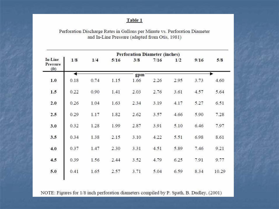
Step 4: Calculate the Lateral Discharge Rate
q = 11.79 d2 hd0.5
q: perforation discharge rate (gpm)
d: perforation diameter (inches)
hd: in-line distal pressure (feet)
Use Table 1 in Guidance
Minimum distal head pressure = 2.5 feet
Total discharge: q x N
N: total perforations in lateral
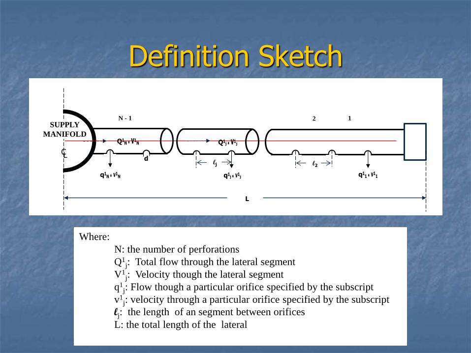
Definition Sketch
SUPPLY
MANIFOLD
N - 1 2 1
Q
q q q
lj l2
Q
d
L
L C
Where:
N: the number of perforations
Q1j: Total flow through the lateral segment
V1j: Velocity though the lateral segment
q1j: Flow though a particular orifice specified by the subscript
v1j: velocity through a particular orifice specified by the subscript
lj: the length of an segment between orifices
L: the total length of the lateral

Step 5: Calculate Manifold Size
In larger systems telescoping manifolds can reduce friction loss
Determine friction factors:
Fi = (9.8 x 10⁻⁴)Qi1.85
Fi: friction factor for manifold segments
0.00098: coefficient of friction for plastic pipe
Qi: flow in manifold segment (gpm)

Step 5: Calculate Manifold Size continued
Take the Fi values in each lateral segment
Calculate pipe segment diameter
21.0
h
FLD
d
i
M
lii
m f

Manifold Diameter Calculation
M = no. of segments
Li = length of ith segment (lat’l spacing)
f= fraction of total head loss (0.1) so limited to 10%
hd=distal head (ft)
21.0
d
i
M
lii
m
h
FLD
f

Steps 6 and 7
Step 6: Determine dose volume
Minimum 5 to 10 times volume of laterals
Do not include manifold vol. if below laterals
Necessary to properly charge the system
Step 7: Calculate min. pump discharge
Add all perforation discharge rates

Step 8: Calculate Total Friction Losses
Force main:
Friction loss = Ld(3.55Qm/ChDd2.63)1.85
Ld: length of force main to network inlet (feet)
3.55: dimensionless coefficient for energy loss
Qm: discharge rate (gpm)
Ch: 150 (Hazen-Williams)
Dd: force main diameter (inches)
Add network losses (1.31 hd)
Add fixture losses (tees, bends, valves etc.)

Design Procedure
End Cleanout

Step 9: Select the Pump Unit
Follow standard engineering practice
Sized on total dynamic head (TDH)
Static losses
Friction losses
Network losses
Use appropriate pump curves

Step 10: Size the pump chamber
Discharge design dose
Provide emergency storage capacity above high water alarm
Include pump on/pump off and alarm
Pump on/off for single pump
Lead/lag on/off for dual pumps
Alarm on separate power circuit from pump(s)
Quick disconnect
Siphon break if pump downhill

Design Alternatives
Divide SAS into zones – must dose all zones before returning to the first
Timed dosing is an option
More applicable to larger flows
Must have certain overrides to prevent under or over dosing
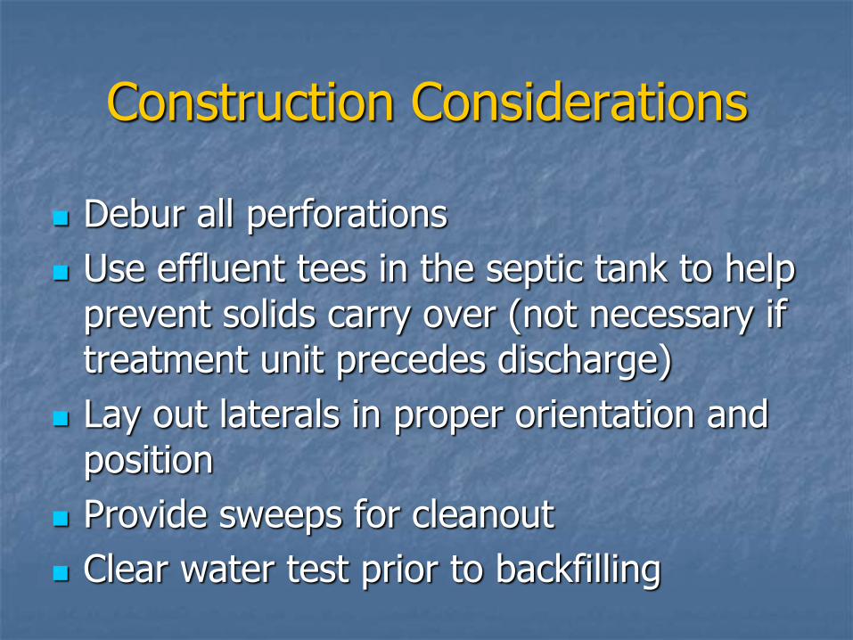
Construction Considerations
Debur all perforations
Use effluent tees in the septic tank to help prevent solids carry over (not necessary if treatment unit precedes discharge)
Lay out laterals in proper orientation and position
Provide sweeps for cleanout
Clear water test prior to backfilling

REGIONAL CONTACT
NAME
Telephone number
Email address

Any questions before we start some examples…

Design Examples
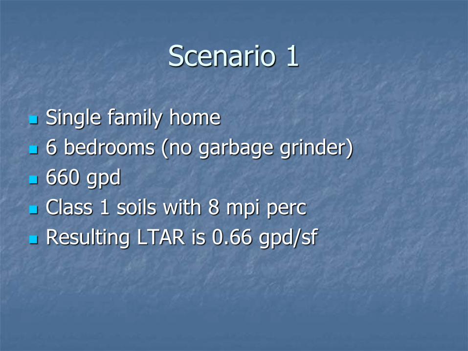
Scenario 1
Single family home
6 bedrooms (no garbage grinder)
660 gpd
Class 1 soils with 8 mpi perc
Resulting LTAR is 0.66 gpd/sf


Steps 1 and 2
Lay out the network
End manifold
5 laterals
Pump chamber is 50 feet from the manifold
SAS is 40 ft long by 25 feet wide
Select perforations size and spacing
1/4 inch diameter perforations
Maximum spacing of 5 feet
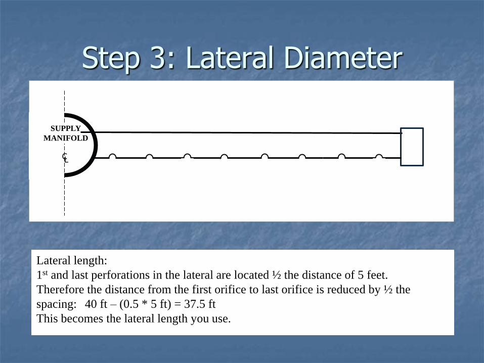
Step 3: Lateral Diameter
SUPPLY
MANIFOLD
L C
Lateral length:
1st and last perforations in the lateral are located ½ the distance of 5 feet.
Therefore the distance from the first orifice to last orifice is reduced by ½ the
spacing: 40 ft – (0.5 * 5 ft) = 37.5 ft
This becomes the lateral length you use.

Step 3: Lateral Diameter
Step 4: Calculate Lateral Discharge Rate
Using Table 1 with a minimum in-line pressure of 2.5 ft to determine discharge
from a 1/4 inch perforation


Step 5: Calculate the Manifold Size
Uniform diameter (simplify construction)
Manifold Length = 4 * 5 ft = 20 ft
Use Table 2 for an end manifold with a lateral discharge rate of 9.36 gpm and 5 ft lateral spacing
The best fit appears to be either:
20-foot long 2 inch manifold; or
44-foot long 3 inch manifold

Lateral Discharge Rate
1.17 gpm discharge per orifice
Total length of lateral is 40 feet
Orifice spacing is 5 feet with the first orifice 2.5 feet from the lateral start and the last orifice 2.5 feet from the end
No. of orifices = 40/5 = 8
Discharge rate = 8 orifices * 1.17 gpm/orifice = 9.4 gpm


Step 6: Determine Dose Volume
Crown of manifold is below lateral invert
Manifold and delivery line drain back.
Minimum dose volume only in laterals
5-10 times the total lateral volume

Dose Volume Continued (2)
Total length of laterals: 5 pipes*40 ft = 200 ft
Area of 1-1/4 in (0.1042 ft) laterals:
πr2 = π*(0.0521)2 = 0.0085 sf
Total pipe volume
0.0085 sf * 200 ft = 1.7 cf
1.7 cf * 7.48 gal/cf = 12.7 gallons

Dose Volume Continued (3)
Min dose volume of 5-10 times pipe volume
12.7 gal (5 to 10) = 64 to 127 gal
Dose frequency: 12 doses per day (dpd)
660 gpd/6 dpd = 55 gal per dose
Manifold and delivery line drain back must be accounted for. Both are 2-in pipes:
(20+70) ft * π * (0.0833)2 ft2 = 1.52 ft3
1.52 ft3 * 7.48 gal/ft3 = 11.4 gal

Dose Volume Continued (4)
Pumping volume = dose volume + drain back volume
= 55 gal + 11.4 gal = 66.4 gal

Step 7: Calculate the Minimum Discharge Rate
Minimum discharge rate =
9.4 gpm/lateral * 5 laterals = 47 gpm

Step 8: Friction Loss Calculation
Friction loss = Ld(3.55Qm/ChDd2.63)1.85
Ld: 50 ft (length of force main)
3.55: dimensionless coefficient for energy loss
Qm: 47 (gpm)
Ch: 150 (Hazen-Williams)
Dd: 2 inches
Friction loss =
(50)((3.55*47)/(150*22.63))1.85 = 2.08 ft
Network loss = 1.31hd = 1.31*2.5 ft = 3.28 ft
Total losses (not including pump chamber or fittings) = 5.36 ft (round up and use 6 ft)

Step 9: Select the Pump Unit
Total Head = Static Head + Friction Losses
If the pump off elevation in the pump chamber is 4 feet below the lateral invert, then the total head is
4 ft + 6 ft = 10 ft
Use head/discharge curves and find a pump capable of pumping 47 gpd against 10 feet of head

Step 10: Size the Pump Chamber
Only one pump will be used (< 2,000 gpd)
Reserve volume = one day’s average daily flow
Pumping Volume 66.4
+ Daily Design Flow 660
726.4 gallons