
Pressure Control Valves€¢ Fitted with Diaphragm to Protect Spring Housing • Set Range 0.5 to 16...
29
Pressure Control Valves Product Information It’s all at Albion
Transcript of Pressure Control Valves€¢ Fitted with Diaphragm to Protect Spring Housing • Set Range 0.5 to 16...

Pressure Control Valves
Product Information
It’s all at Albion

Dimensions in mmThis data sheet is designed as a guide and should not be regarded as wholly accurate in every detail. We reserve the right to amend the specification of any product without notice.
Gunmetal Safety Valve Features• Screwed BSP Parallel (ISO 228) or flange connection• Body Gunmetal• Suitable for Gases and Liquids• Fitted with Diaphragm to Protect Spring Housing• Set Range 0.5 to 16 Bar• WRAS Approved• ISO 4126-1, PED 2014/68/EU• Marine Approvals - GL, DNV• ATEX Approval Available at Extra Cost• 5 Year Warranty• Test Certificate to EN10204-3.1 Available on Request
ART 642 & 642 FL
Typical Applications
• Pressure Vessels• Mechanical engineering• Pump protection• Pressure booster systems water/air-side• Cooling/Chilling Systems• Steam and industrial boiler systems
V2
N. Part Name Materials1 Body Gunmetal
2 Housing Cap Brass / Gunmetal
3 Spring Housing Brass / Gunmetal
4 Lifting Lever Stainless Steel CF8M
5 Spring Stainless Steel 302
6 Seat-Seal PTFE
7 Diaphragm EPDM
Technical DataMax Pressure 16 BarWorking Temperature EPDM Diaphragm -50°C to +195°C
DN ½“ ¾“ 1“ 1¼“ 1½“ 2“ 2½“
L 35 42 45 47 58 68 80
Lmax 63 75 78 100 140 150 155
H 90 106 120 150 192 229 275
H1 DIN / ANSI 180 / 180 216 / 216 265 / 265 312 / 312 371 / 371
Hmax 102 120 133 153 210 252 298
h 28 36 38 37 45 55 65
h1 DIN / ANSI 60 / 60 66 / 66 73 / 73 83 / 83 96 / 96
D DIN / ANSI 115 / 110 140 / 115 150 / 125 165 / 150 185 / 180
d1 DIN / ANSI 65 / 50.8 76 / 63.5 84 / 73 99 / 92.1118 / 104.8
SW 27 34 41 50 60 70 90
do 13 15 18 23 30 39 48
K / nxd (DIN) 85 / 4x14 100 / 4x18 110 / 4x18 125 / 4x18 145 / 4x18
K / nxd (ANSI)79.4 / 4x15.9
88.9 / 4x15.9
98.4 / 4x15.9
120.7 / 4x19.1
139.7 / 4x19.1
kg 0.5 0.8 1.1 1.7 3.3 5.8 8.9
kg FLDIN / FLANSI
2.0 / 1.9 3.4 / 2.9 4.1 / 3.5 8.4 / 7.9 12.0 / 11.8

Dimensions in mmThis data sheet is designed as a guide and should not be regarded as wholly accurate in every detail. We reserve the right to amend the specification of any product without notice.
Discharge Capacities
ART 642 & 642 FL
DN 1/2” 3/4” 1” 1 1/4”
Bar Nm3/h kg/h m3/h kW Nm3/h kg/h m3/h kW Nm3/h kg/h m3/h kW Nm3/h kg/h m3/h kW0.5 74 56 2.1 36 85 64 2.7 41 105 79 3.4 51 208 157 6.6 1011 106 84 2.9 53 124 97 3.7 62 156 123 4.6 78 315 251 8.9 1582 173 136 4.1 84 204 159 5.2 98 266 208 6.5 128 525 413 12.6 2543 233 181 5.0 110 279 217 6.4 131 372 289 8.0 175 729 570 15.4 3444 293 226 5.8 135 357 276 7.4 164 477 368 9.2 219 916 710 17.7 4235 352 272 6.5 159 438 338 8.2 198 574 443 10.3 260 1103 851 19.8 5006 412 318 7.1 184 512 395 9.0 228 671 518 11.3 299 1289 992 21.7 5767 471 364 7.7 207 586 452 9.7 258 768 593 12.2 338 1476 1130 23.5 6508 531 410 8.2 231 660 509 10.4 287 865 668 13.1 376 1662 1269 25.1 7249 591 456 8.7 254 734 566 11.0 315 963 743 13.9 414 1849 1408 26.6 79510 650 502 9.2 276 808 623 11.6 344 1060 818 14.6 451 2036 1546 28.1 86511 710 548 9.6 299 882 680 12.2 372 1157 892 15.3 487 2222 1683 29.4 93812 770 594 10.1 321 956 738 12.7 399 1254 967 16.0 523 2409 1820 30.7 100813 829 640 10.5 343 1030 795 13.3 426 1351 1042 16.7 559 2595 1958 32.0 107814 889 686 10.9 365 1104 852 13.8 453 1448 1117 17.3 594 2782 2097 33.2 114515 948 732 11.3 386 1178 909 14.3 480 1545 1192 17.9 629 2969 2234 34.4 121316 1008 778 11.6 407 1252 966 14.7 506 1643 1267 18.5 664 3155 2372 35.5 1282
DN 1 1/2” 2” 2 1/2”
Bar Nm3/h kg/h m3/h kW Nm3/h kg/h m3/h kW Nm3/h kg/h m3/h kW0.5 285 215 9.2 138 494 372 15.5 239 729 549 23.6 3521 414 331 12.5 208 700 559 21.1 352 1034 826 31.9 5202 677 534 17.6 327 1145 902 29.8 553 1734 1366 45.1 8383 931 728 21.6 439 1573 1230 36.5 741 2383 1862 55.2 11234 1169 906 24.9 540 1975 1532 42.1 913 2992 2320 63.8 13835 1407 1085 27.9 638 2378 1834 47.1 1078 3602 2778 71.3 16336 1645 1266 30.5 736 2780 2139 51.6 1243 4211 3240 78.1 18837 1883 1441 33.0 830 3182 2436 55.7 1403 4821 3690 84.4 21258 2121 1619 35.2 924 3585 2737 59.5 1561 5430 4146 90.2 23659 2359 1796 37.4 1014 3987 3036 63.2 1713 6040 4599 95.7 259510 2597 1973 39.4 1104 4389 3334 66.6 1866 6649 5050 100.8 282711 2835 2148 41.3 1197 4792 3630 69.8 2023 7259 5499 105.8 306512 3074 2322 43.1 1286 5194 3925 72.9 2173 7868 5945 110.5 329113 3312 2498 44.9 1376 5597 4222 75.9 2325 8478 6396 115.0 352214 3550 2675 46.6 1461 5999 4521 78.8 2468 9087 6848 119.3 373915 3788 2850 48.2 1548 6401 4817 81.5 2616 9697 7297 123.5 396216 4026 3026 49.8 1635 6804 5114 84.2 2764 10306 7747 127.6 4187
Seat-Seal/Diaphragm OptionsOption Materials Type Working Temp.
PTFE/EPDM Polytetrafluorethylen/Ethylen-Propylene-Diene (Standard) Flat seal and moulded diaphragm –50°C to +195°C
EPDM/EPDM Ethylen-Propylene-Diene/Ethylen-Propylene-Diene Flat seal and moulded diaphragm –50°C to +150°C
PTFE/FKM Polytetrafluorethylen/Fluorcarbon Flat seal and moulded diaphragm –30°C to +200°C
FKM/FKM Fluorcarbon/Fluorcarbon Elastomere seals and moulded diaphragm –20°C to +200°C
V2

Dimensions in mmThis data sheet is designed as a guide and should not be regarded as wholly accurate in every detail. We reserve the right to amend the specification of any product without notice.
ART 645 & 645 FL
Gunmetal High Discharge Safety ValveFeatures• Screwed BSP Parallel (ISO 228) or flange connection• Body Gunmetal• Suitable for Gases and Liquids• Fitted with Diaphragm to Protect Spring Housing• Set Range 0.5 to 16 Bar• WRAS Approved• ISO 4126-1, PED 2014/68/EU• Marine Approvals - GL, DNV• ATEX Approval Available at Extra Cost• 5 Year Warranty• Test Certificate to EN10204-3.1 Available on Request• High Capacity Discharge
Typical Applications
• Pressure Vessels• Mechanical engineering• Pump protection• Pressure booster systems water/air-side• Cooling/Chilling Systems• Steam and industrial boiler systems
V3
N. Part Name Materials1 Body Gunmetal2 Housing Cap Brass / Gunmetal3 Spring Housing Brass / Gunmetal4 Lifting Lever Stainless Steel CF8M5 Spring Stainless Steel 3026 Seat-Seal PTFE7 Diaphragm EPDM
Technical DataMax Pressure 16 BarWorking Temperature EPDM Diaphragm -50°C to +195°C
DN ½“ ¾“ 1“ 1¼“ 1½“ 2“
DN1 3/4“ 1“ 1¼“ 1½“ 2“ 2½“
L 36 43 47 58 68 80
Lmax 63 78 100 140 150 155
H 90 115 146 192 229 275
H1 DIN / ANSI 206 / 206 258 / 258 302 / 302 358 / 358
Hmax 102 133 148 210 252 298
h 30 35 37 45 55 65
h1 DIN / ANSI 60 / 60 66 / 66 73 / 73 83 / 83
D DIN / ANSI 115 / 110 140 / 115 150 / 125 165 / 150
d1 DIN / ANSI 65 / 50.8 76 / 63.5 84 / 73 99 / 92.1
SW1 27 34 41 55 65 80
SW2 34 41 50 60 70 90
do 13 18 23 30 39 48
K / nxd (DIN) 85 / 4x14 100 / 4x18 110 / 4x18 125 / 4x18
K / nxd (ANSI) 79.4 / 4x15.9 88.9 / 4x15.9 98.4 / 4x15.9120.7 / 4x19.1
kg 0.5 0.9 1.6 3.3 5.8 8.9
kg FLDIN / FLANSI
2.6 / 2.4 4.8 / 4.3 7.5 / 6.9 11.3 / 10.8

Dimensions in mmThis data sheet is designed as a guide and should not be regarded as wholly accurate in every detail. We reserve the right to amend the specification of any product without notice.
ART 645 & 645 FL
DN 1 1/4” 1 1/2” 2”
Bar Nm3/h kg/h m3/h kW Nm3/h kg/h m3/h kW Nm3/h kg/h m3/h kW0.5 346 261 10.3 167 559 421 16.5 264 867 653 25.7 4091 505 403 13.9 254 802 641 22.4 403 1241 991 34.8 6242 816 643 19.7 394 1301 1025 31.7 629 2049 1615 49.2 9913 1117 873 24.1 526 1783 1393 38.8 840 2806 2194 60.3 13234 1429 1108 27.9 660 2283 1770 44.8 1055 3591 2785 69.6 16605 1720 1327 31.1 780 2747 2120 50.1 1246 4322 3334 77.8 19606 2011 1547 34.1 899 3212 2472 54.8 1436 5053 3888 85.2 22607 2302 1762 36.9 1014 3677 2815 59.2 1621 5785 4428 92.0 25498 2593 1979 39.4 1129 4142 3162 63.3 1804 6516 4975 98.4 28389 2884 2196 41.8 1239 4607 3508 67.2 1980 7248 5519 104.4 311510 3175 2411 44.0 1350 5072 3852 70.8 2156 7979 6060 110.0 339211 3466 2625 46.2 1463 5537 4195 74.3 2338 8710 6598 115.4 367812 3757 2838 48.2 1571 6002 4535 77.6 2511 9442 7134 120.5 394913 4048 3054 50.2 1681 6467 4879 80.7 2687 10173 7675 125.4 422614 4339 3270 52.1 1785 6932 5224 83.8 2852 10905 8218 130.2 448715 4630 3484 53.9 1892 7397 5566 86.7 3022 11636 8756 134.7 475416 4921 3699 55.9 1999 7862 5910 89.3 3194 12367 9297 139.1 5024
DN 1/2” 3/4” 1”
Bar Nm3/h kg/h m3/h kW Nm3/h kg/h m3/h kW Nm3/h kg/h m3/h kW0.5 77 58 2.3 37 141 106 4.3 68 208 157 6.6 1011 114 91 3.0 57 222 177 5.8 112 315 251 8.9 1582 188 148 4.3 91 366 288 8.3 177 525 413 12.6 2543 256 200 5.3 121 499 390 10.1 235 729 570 15.4 3444 327 253 6.1 151 626 486 11.7 290 916 710 17.7 4235 393 303 6.8 178 754 582 13.1 342 1103 851 19.8 5006 460 354 7.5 206 882 678 14.3 394 1289 992 21.7 5767 526 403 8.1 232 1009 773 15.5 445 1476 1130 23.5 6508 593 453 8.6 258 1137 868 16.5 495 1662 1269 25.1 7249 660 502 9.1 283 1265 963 17.5 543 1849 1408 26.6 79510 726 551 9.6 309 1392 1057 18.5 592 2036 1546 28.1 86511 793 601 10.1 335 1520 1151 19.4 642 2222 1683 29.4 93812 859 649 10.6 359 1647 1245 20.2 689 2409 1820 30.7 100813 926 698 11.0 385 1775 1339 21.1 737 2595 1958 32.0 107814 992 748 11.4 408 1903 1434 21.9 783 2782 2097 33.2 114515 1059 797 11.8 433 2030 1528 22.6 830 2969 2234 34.4 121316 1126 846 12.2 457 2158 1622 23.4 877 3155 2372 35.5 1282
Discharge Capacities
Seat-Seal/Diaphragm OptionsOption Materials Type Working Temp.
PTFE/EPDM Polytetrafluorethylen/Ethylen-Propylene-Diene (Standard) Flat seal and moulded diaphragm –50°C to +195°C
EPDM/EPDM Ethylen-Propylene-Diene/Ethylen-Propylene-Diene Flat seal and moulded diaphragm –50°C to +150°C
PTFE/FKM Polytetrafluorethylen/Fluorcarbon Flat seal and moulded diaphragm –30°C to +200°C
FKM/FKM Fluorcarbon/Fluorcarbon Elastomere seals and moulded diaphragm –20°C to +200°C
V3

Dimensions in mmThis data sheet is designed as a guide and should not be regarded as wholly accurate in every detail. We reserve the right to amend the specification of any product without notice.
Brass Atmospheric Discharge Safety Valve
ART 810
Typical Applications
• Compressors• Pressure booster plants air-side• Paint spray shops• Pneumatic control units• Transport- and railway applications
Safety valves are set and sealed at the factory.
Technical DataMax Pressure 50 BarWorking Temperature PTFE Seal -60°C to +225°C
N. Part Name Materials
1 Inlet body Brass CW617N
2 Outlet body Brass CW617N
3 Internal parts Brass CW617N
4 Spring Stainless steel 1.4568
V1
DN ¼“ 3/8” ½“ ¾“ 1“
H 60 65 78 66 79 94 104 111
h 10 10 10 12 12 12 12 14
SW 19 24 24 27 27 34 34 41
do 7,5 10 10 11 11 16 16 20
kg 0,1 0,14 0,16 0,17 0,19 0,35 0,4 0,6
Features• Male BSP Parallel (ISO 228)• Body Brass• Suitable for neutral gases and air• Set pressure: 0.2 to 50 bar• ISO 4126-1, PED 2014/68/EU• Marine Approvals - GL, LR EMEA, BV, ABS, DNV, RS• ATEX Approval Available at Extra Cost• 24 Month Warranty• Test Certificate to EN10204-3.1 Available on Request• Standard Capacity Discharge

Dimensions in mmThis data sheet is designed as a guide and should not be regarded as wholly accurate in every detail. We reserve the right to amend the specification of any product without notice.
Discharge Capacities
ART 810
Seat-Seal/Diaphragm OptionsOption Materials Type Working Temp.FKM Fluorocarbon Elastomere flat seal 0,2 – 25 bar –20°C to +200°CPTFE Polytetrafluoroethylene Flat seal 25,1 – 50 bar –60°C to +225°CAgainst surchargePTFE Polytetrafluoroethylene Flat seal 0,2 – 25 bar –60°C to +225°C
V1
DN 1/4“ 3/8“ 1/2“ 3/4“ 1“Bar0,2 20 35 46 100 1330,3 25 45 54 119 1440,4 29 52 67 137 1670,5 32 58 74 158 1850,6 35 64 82 172 2110,7 37 70 87 187 2350,8 41 74 95 200 2600,9 43 80 101 213 2821 46 85 107 227 305
1,5 60 108 137 286 4082 73 132 166 346 5063 100 182 222 465 6994 125 228 279 584 8895 151 274 336 703 10706 176 321 393 821 12517 201 367 450 940 14328 227 414 507 1059 16139 252 460 564 1178 179410 278 507 621 1297 197511 303 553 678 1416 215612 329 599 735 1535 233713 354 646 791 1654 251814 380 692 848 1773 270015 405 739 905 1891 288116 431 785 962 2010 306217 456 832 1019 2129 324318 482 878 1076 2248 342419 507 925 1133 2367 360520 533 971 1190 2486 378621 558 1017 1247 2605 396722 584 1064 1304 2724 414823 609 1110 1361 2843 432924 635 1157 1417 2961 451025 660 1203 1474 3080 469126 685 1250 1531 3199 487227 711 1296 1588 3318 505328 736 1342 1645 3437 523429 762 1389 1702 3556 541530 787 1435 1759 3675 559731 813 1482 1816 3794 577832 838 1528 1873 3913 595933 864 1575 1930 4031 614034 889 1621 1986 4150 632135 915 1667 2043 4269 650236 940 1714 2100 4388 668337 966 1760 2157 4507 686438 991 1807 2214 4626 704539 1017 1853 2271 4745 722640 1042 1900 2328 4864 740741 1068 1946 2385 4983 758842 1093 1993 2442 5101 776943 1119 2039 2499 5220 795044 1144 2085 2556 5339 813145 1170 2132 2612 5458 831346 1195 2178 2669 5577 849447 1220 2225 2726 5696 867548 1246 2271 2783 5815 885649 1271 2318 2840 5934 903750 1297 2364 2897 6053 9218
Blowing-off rates at 10% above set pressure

Dimensions in mmThis data sheet is designed as a guide and should not be regarded as wholly accurate in every detail. We reserve the right to amend the specification of any product without notice.
Stainless Steel Safety ValveFeatures• Screwed BSP Parallel (ISO 228)• Body Stainless Steel• Suitable for Gases, Liquids & Steam• Set pressure: 0.5 to 70 bar• ISO 4126-1, PED 2014/68/EU• Marine Approvals - GL, LR EMEA, ABS, DNV, BV, RS• ATEX Approval Available at Extra Cost• 24 Month Warranty• Test Certificate to EN10204-3.1 Available on Request
ART 451
Typical Applications
• Chemical plants, biogas plants• Process equipment construction and medical technology (sterilizers, autoclaves) • Secondary areas in the food-, beverage-, pharmaceutical- and cosmetics-industriesSafety valves are set and sealed at the factory.
Technical DataMax Pressure 70 BarWorking Temperature PTFE Seal -60°C to +225°C
DN ½“ ¾“ 1“ 1¼“
G11/2“ (15)
1“ (25)
1“ (25)
3/4“ (20)
1 1/4“ (32)
1 1/2“ (32)
2“ (50)
1 1/2“ (40)
2“ (50)
L 34 40 40 42 43 50 61 61 61
Lmax 65 65 65 91 91 92 92 92 92
H / H1
79 / 79
77 / 77
131 / 131
137 / 137
138 / 152
178 / 196
241 / 263
241 / 263
241 / 263
H1 / H11
93 / 93
91 / 91
149 / 149
154 / 154
158 / 174
192 / 210
264 / 286
264 / 286
264 / 286
H2 / H21
79 / 79
77 / 77
131 / 131
138 / 138
139 / 153
175 / 193
241 / 263
241 / 263
241 / 263
Hmax / Hmax1
105 / 105
103 / 103
164 / 164
169 / 169
173 / 184
207 / 225
277 / 299
277 / 299
277 / 299
h 28 30 30 31 39 45 55 69 74
h1 15 15 15 16 16 18 20 23 25
SW1 30 30 30 36 36 46 55 55 70
SW2 - 40 40 32 50 58 70 70 70
do 15,8 15,8 15,8 15,8 18 23 30,3 30,3 30,3
kg 0,4 0,4 0,8 1,0 1,0 1,8 4,0 4,0 4,0
bar 0,52-25 0,52-25 25,1-70 0,52-70 0,5-70 0,5-70 0,5-70 0,5-70 0,5-70
N. Part Name Materials
1 Inlet body Stainless steel 1.4404
2 Outlet body Stainless steel 1.4408
3 Internal parts Stainless steel 1.4404
4 Spring Stainless steel 1.4310
4 Bellows (optional) Stainless steel 1.4571
¹Dimension for the version with bellows²Version with bellows only available from 1 bar
V1
Dimensions in mmThis data sheet is designed as a guide and should not be regarded as wholly accurate in every detail. We reserve the right to amend the specification of any product without notice.
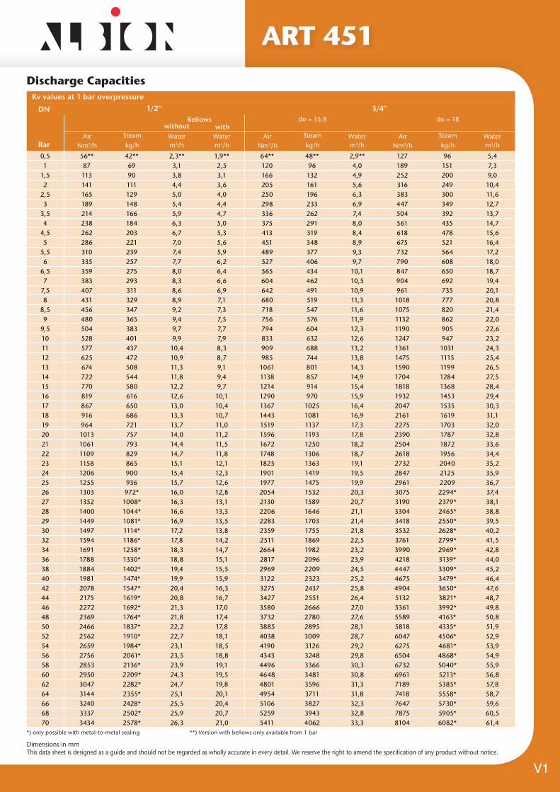
Discharge Capacities
ART 451
V1
DN 1/2“ 3/4“Bellows do = 15,8 do = 18
without withAir Steam Water Water Air Steam Water Air Steam Water
Bar Nm3/h kg/h m3/h m3/h Nm3/h kg/h m3/h Nm3/h kg/h m3/h
0,5 56** 42** 2,3** 1,9** 64** 48** 2,9** 127 96 5,41 87 69 3,1 2,5 120 96 4,0 189 151 7,3
1,5 113 90 3,8 3,1 166 132 4,9 252 200 9,02 141 111 4,4 3,6 205 161 5,6 316 249 10,4
2,5 165 129 5,0 4,0 250 196 6,3 383 300 11,63 189 148 5,4 4,4 298 233 6,9 447 349 12,7
3,5 214 166 5,9 4,7 336 262 7,4 504 392 13,74 238 184 6,3 5,0 375 291 8,0 561 435 14,7
4,5 262 203 6,7 5,3 413 319 8,4 618 478 15,65 286 221 7,0 5,6 451 348 8,9 675 521 16,4
5,5 310 239 7,4 5,9 489 377 9,3 732 564 17,26 335 257 7,7 6,2 527 406 9,7 790 608 18,0
6,5 359 275 8,0 6,4 565 434 10,1 847 650 18,77 383 293 8,3 6,6 604 462 10,5 904 692 19,4
7,5 407 311 8,6 6,9 642 491 10,9 961 735 20,18 431 329 8,9 7,1 680 519 11,3 1018 777 20,8
8,5 456 347 9,2 7,3 718 547 11,6 1075 820 21,49 480 365 9,4 7,5 756 576 11,9 1132 862 22,0
9,5 504 383 9,7 7,7 794 604 12,3 1190 905 22,610 528 401 9,9 7,9 833 632 12,6 1247 947 23,211 577 437 10,4 8,3 909 688 13,2 1361 1031 24,312 625 472 10,9 8,7 985 744 13,8 1475 1115 25,413 674 508 11,3 9,1 1061 801 14,3 1590 1199 26,514 722 544 11,8 9,4 1138 857 14,9 1704 1284 27,515 770 580 12,2 9,7 1214 914 15,4 1818 1368 28,416 819 616 12,6 10,1 1290 970 15,9 1932 1453 29,417 867 650 13,0 10,4 1367 1025 16,4 2047 1535 30,318 916 686 13,3 10,7 1443 1081 16,9 2161 1619 31,119 964 721 13,7 11,0 1519 1137 17,3 2275 1703 32,020 1013 757 14,0 11,2 1596 1193 17,8 2390 1787 32,821 1061 793 14,4 11,5 1672 1250 18,2 2504 1872 33,622 1109 829 14,7 11,8 1748 1306 18,7 2618 1956 34,423 1158 865 15,1 12,1 1825 1363 19,1 2732 2040 35,224 1206 900 15,4 12,3 1901 1419 19,5 2847 2125 35,925 1255 936 15,7 12,6 1977 1475 19,9 2961 2209 36,726 1303 972* 16,0 12,8 2054 1532 20,3 3075 2294* 37,427 1352 1008* 16,3 13,1 2130 1589 20,7 3190 2379* 38,128 1400 1044* 16,6 13,3 2206 1646 21,1 3304 2465* 38,829 1449 1081* 16,9 13,5 2283 1703 21,4 3418 2550* 39,530 1497 1114* 17,2 13,8 2359 1755 21,8 3532 2628* 40,232 1594 1186* 17,8 14,2 2511 1869 22,5 3761 2799* 41,534 1691 1258* 18,3 14,7 2664 1982 23,2 3990 2969* 42,836 1788 1330* 18,8 15,1 2817 2096 23,9 4218 3139* 44,038 1884 1402* 19,4 15,5 2969 2209 24,5 4447 3309* 45,240 1981 1474* 19,9 15,9 3122 2323 25,2 4675 3479* 46,442 2078 1547* 20,4 16,3 3275 2437 25,8 4904 3650* 47,644 2175 1619* 20,8 16,7 3427 2551 26,4 5132 3821* 48,746 2272 1692* 21,3 17,0 3580 2666 27,0 5361 3992* 49,848 2369 1764* 21,8 17,4 3732 2780 27,6 5589 4163* 50,850 2466 1837* 22,2 17,8 3885 2895 28,1 5818 4335* 51,952 2562 1910* 22,7 18,1 4038 3009 28,7 6047 4506* 52,954 2659 1984* 23,1 18,5 4190 3126 29,2 6275 4681* 53,956 2756 2061* 23,5 18,8 4343 3248 29,8 6504 4868* 54,958 2853 2136* 23,9 19,1 4496 3366 30,3 6732 5040* 55,960 2950 2209* 24,3 19,5 4648 3481 30,8 6961 5213* 56,862 3047 2282* 24,7 19,8 4801 3596 31,3 7189 5385* 57,864 3144 2355* 25,1 20,1 4954 3711 31,8 7418 5558* 58,766 3240 2428* 25,5 20,4 5106 3827 32,3 7647 5730* 59,668 3337 2502* 25,9 20,7 5259 3943 32,8 7875 5905* 60,570 3434 2578* 26,3 21,0 5411 4062 33,3 8104 6082* 61,4
Kv values at 1 bar overpressure
*) only possible with metal-to-metal sealing **) Version with bellows only available from 1 bar

Dimensions in mmThis data sheet is designed as a guide and should not be regarded as wholly accurate in every detail. We reserve the right to amend the specification of any product without notice.
Discharge Capacities
ART 451
V1
DN 1“ 1 1/4“
Air Steam Water Air Steam WaterBar Nm3/h kg/h m3/h Nm3/h kg/h m3/h
0,5 199 150 8,8 353 266 15,4
1 291 232 12,0 515 411 20,8
1,5 390 309 14,7 683 542 25,5
2 489 385 16,9 832 656 29,4
2,5 583 457 18,9 1012 793 32,9
3 681 532 20,8 1182 924 36,0
3,5 768 597 22,4 1333 1036 38,9
4 855 663 24,0 1484 1151 41,6
4,5 942 729 25,4 1635 1265 44,1
5 1029 794 26,8 1786 1378 46,5
5,5 1116 860 28,1 1937 1492 48,8
6 1203 926 29,3 2088 1607 50,9
6,5 1290 990 30,5 2239 1719 53,0
7 1377 1054 31,7 2390 1830 55,0
7,5 1464 1119 32,8 2542 1943 56,9
8 1552 1184 33,9 2693 2056 58,8
8,5 1639 1249 34,9 2844 2168 60,6
9 1726 1314 35,9 2995 2281 62,4
9,5 1813 1379 36,9 3146 2392 64,1
10 1900 1443 37,9 3297 2504 65,8
11 2074 1571 39,7 3599 2727 69,0
12 2248 1699 41,5 3902 2948 72,0
13 2422 1827 43,2 4204 3172 75,0
14 2596 1957 44,8 4506 3396 77,8
15 2771 2085 46,4 4808 3618 80,5
16 2945 2214 47,9 5111 3842 83,2
17 3119 2339 49,4 5413 4059 85,7
18 3293 2467 50,8 5715 4281 88,2
19 3467 2594 52,2 6017 4503 90,6
20 3641 2723 53,6 6320 4726 93,0
21 3816 2852 54,9 6622 4950 95,3
22 3990 2981 56,2 6924 5173 97,5
23 4164 3109 57,5 7226 5396 99,7
24 4338 3238 58,7 7529 5619 101,9
25 4512 3366 59,9 7831 5842 104,0
26 4686 3496* 61,1 8133 6067* 106,0
27 4860 3626* 62,3 8435 6293* 108,0
28 5035 3756* 63,4 8738 6518* 110,0
29 5209 3886* 64,5 9040 6744* 112,0
30 5383 4005* 65,6 9342 6951* 113,9
32 5731 4265* 67,8 9947 7401* 117,6
34 6080 4524* 69,9 10551 7851* 121,2
36 6428 4783* 71,9 11156 8301* 124,8
38 6776 5042* 73,9 11760 8751* 128,2
40 7124 5301* 75,8 12365 9200* 131,5
42 7473 5562* 77,6 12969 9653* 134,8
44 7821 5823* 79,5 13574 10105* 137,9
46 8169 6083* 81,3 14178 10558* 141,0
48 8518 6344* 83,0 14783 11011* 144,1
50 8866 6606* 84,7 15387 11464* 147,0
52 9214 6867* 86,4 15992 11917* 149,9
54 9563 7134* 88,0 16596 12380* 152,8
56 9911 7412* 89,7 17200 12864* 155,6
58 10259 7681* 91,2 17805 13330* 158,4
60 10608 7943* 92,8 18409 13786* 161,1
62 10956 8206* 94,3 19014 14242* 163,7
64 11304 8469* 95,8 19618 14699* 166,3
66 11652 8732* 97,3 20223 15155* 168,9
68 12001 8998* 98,8 20827 15616* 171,5
70 12349 9269* 100,2 21432 16086* 174,0
Kv values at 1 bar overpressure
*) only possible with metal-to-metal sealing

Dimensions in mmThis data sheet is designed as a guide and should not be regarded as wholly accurate in every detail. We reserve the right to amend the specification of any product without notice.
ART 451
Seat-Seal/Diaphragm OptionsOption Materials Type Working Temp.
NBR Nitrile rubber Elastomere moulded seal with metallic support up to 25 bar –30°C to +130°C
EPDM Ethylene propylene diene Elastomere moulded seal with metallic support up to 25 bar –40°C to +170°C
FKM Fluorcarbon Elastomere moulded seal with metallic support up to 25 bar –20°C to +200°C
PTFE Polytetrafluoroethylene Flat seal up to 25 bar –60°C to +225°C
PTFE+Kohle Polytetrafluoroethylene + carbon Flat seal from 25 bar –60°C to +225°C
Against surcharge
FFKM Perfluorinated rubber Elastomere moulded seal with metallic support up to 25 bar –10°C to +260°C
MD Metal-to-metal sealing Flat seal –60°C to +400°C
V1

Dimensions in mmThis data sheet is designed as a guide and should not be regarded as wholly accurate in every detail. We reserve the right to amend the specification of any product without notice.
Stainless Steel Safety ValveFeatures• Male BSP Parallel (ISO 228)• Body Stainless Steel• Suitable for Gases, Liquids & Steam• Set pressure: 0.2 to 25 bar• ISO 4126-1, PED 2014/68/EU• Marine Approvals - GL, LR EMEA, ABS, DNV, RS• ATEX Approval Available at Extra Cost• 24 Month Warranty• Test Certificate to EN10204-3.1 Available on Request
ART 452
Typical Applications
• Chemical plants, biogas plants• Desalination plants• Process equipment construction and medical technology • Shipbuilding industry and marine equipment• Secondary areas in the food-, beverage-, pharmaceutical- and cosmetics-industries
Safety valves are set and sealed at the factory.
Technical DataMax Pressure 25 BarWorking Temperature PTFE Seal -60°C to +225°C
DN 3/8” ½“ ¾“ 1“
L 30 36 43 47
Lmax 72 72 72 72
H 77,5 82 90,5 101
H1 98 107 117 127
h 17 19 20 22
h1 12 15 16 18
SW1 24 27 34 38
SW2 22 26 32 38
do 9 13 15 18
kg 0,3 0,4 0,6 0,8
N. Part Name Materials
1 Inlet body Stainless steel 1.4408
2 Outlet body Stainless steel 1.4408
3 Internal parts Stainless steel 1.4401
4 Spring Stainless steel 1.4310
V1

Dimensions in mmThis data sheet is designed as a guide and should not be regarded as wholly accurate in every detail. We reserve the right to amend the specification of any product without notice.
Discharge Capacities
ART 452
Seat-Seal/Diaphragm OptionsOption Materials Type Working Temp.
NBR Nitrile rubber Elastomere flat seal –30°C to +130°C
EPDM Ethylene propylene diene Elastomere flat seal –50°C to +150°C
FKM Fluorcarbon Elastomere flat seal –20°C to +200°C
PTFE Polytetrafluoroethylene Flat seal from 0,5 bar –60°C to +225°C
V1
DN 3/8“ 1/2“ 3/4“ 1“
Air Steam Water Air Steam Water Air Steam Water Air Steam WaterBar Nm3/h kg/h m3/h Nm3/h kg/h m3/h Nm3/h kg/h m3/h Nm3/h kg/h m3/h
0,2 18 14 0,6 41 33 1,3 58 46 1,8 77 61 2,6
0,5 25 20 0,8 62 50 1,9 81 65 2,5 111 89 3,7
0,8 34 27 1,0 82 65 2,3 107 85 3,1 145 115 4,7
1 39 31 1,1 95 75 2,6 124 97 3,4 167 132 5,2
1,5 53 41 1,4 127 99 3,3 169 132 4,2 243 191 6,3
2 65 51 1,6 159 124 3,8 212 165 4,8 310 243 7,3
2,5 80 62 1,8 190 147 4,3 257 200 5,4 370 288 7,7
3 91 71 2,0 217 169 4,7 295 229 5,9 439 341 8,5
3,5 105 81 2,2 250 193 5,1 338 262 6,4 512 396 9,2
4 119 92 2,3 278 214 5,5 383 296 7,0 570 440 9,8
4,5 134 103 2,5 306 236 5,8 429 331 7,4 628 485 10,4
5 146 113 2,7 340 263 6,1 469 362 7,8 687 530 10,9
5,5 159 122 2,8 369 285 6,4 509 392 8,2 745 574 11,5
6 174 135 2,9 398 307 6,7 557 430 8,6 804 620 12,0
6,5 187 144 3,0 442 341 7,0 598 461 8,9 864 666 12,5
7 200 154 3,1 471 364 7,2 638 492 9,7 934 721 12,9
7,5 216 167 3,3 510 393 7,5 678 523 10,1 993 766 13,4
8 246 190 3,4 549 423 7,7 719 555 10,4 1052 812 13,8
8,5 260 200 3,6 580 447 8,0 759 586 10,7 1111 857 14,3
9 274 211 3,7 610 471 8,2 799 617 11,0 1170 903 14,7
9,5 287 222 3,8 641 495 8,4 840 648 11,3 1229 948 15,1
10 301 232 3,9 672 518 8,6 880 679 11,6 1288 994 15,5
11 329 254 4,1 734 566 9,1 961 741 12,2 1406 1085 16,2
12 357 275 4,2 795 613 9,5 1042 803 12,7 1524 1176 16,9
13 384 296 4,4 857 661 9,8 1122 866 13,3 1643 1267 17,6
14 412 318 4,6 918 708 10,2 1203 928 13,8 1761 1358 18,3
15 439 339 4,7 980 756 10,6 1284 990 14,3 1879 1449 18,9
16 467 360 4,9 1042 803 10,9 1364 1052 14,7 1997 1540 19,6
17 495 382 5,0 1103 851 11,3 1445 1115 15,2 2115 1632 20,2
18 522 403 5,2 1165 899 11,6 1526 1177 15,6 2233 1723 20,8
19 550 424 5,3 1226 946 11,9 1606 1239 16,0 2351 1814 21,3
20 577 446 5,5 1288 994 12,2 1687 1301 16,5 2469 1905 21,9
21 605 467 5,6 1350 1041 12,5 1768 1364 16,9 2587 1996 22,4
22 633 488 5,7 1411 1089 12,8 1848 1426 17,3 2705 2087 22,9
23 660 509 5,9 1473 1136 13,1 1929 1488 17,6 2823 2178 23,5
24 688 531 6,0 1534 1184 13,4 2010 1550 18,0 2942 2269 24,0
25 716 552 6,1 1596 1231 13,6 2090 1613 18,4 3060 2360 24,5
Kv values at 1 bar overpressure

Dimensions in mmThis data sheet is designed as a guide and should not be regarded as wholly accurate in every detail. We reserve the right to amend the specification of any product without notice.
Gunmetal Overflow & Pressure Relief Valves
Features• Screwed BSP Parallel (ISO 228)• Body Gunmetal• Suitable for Gases and Liquids• Set pressure: 0.2 to 20 bar• PED 2014/68/EU• Marine Approvals - GL, LR EMEA, ABS, BV, RS• ATEX Approval Available at Extra Cost• 24 Month Warranty• Test Certificate to EN10204-3.1 Available on Request
ART 617
Typical Applications• Pump protection• Test rig construction• Process equipment construction• Shipbuilding industry and marine equipment• De-icing technology• Mechanical engineering• Industrial applications
Technical DataMax Pressure 20 BarWorking Temperature PTFE Seal -60°C to +225°C
DN 3/8” ½“ ¾“ 1“ 1¼“ 1½“ 2“
L 27 30 33 40 45 50 60H/H1 60/63 69/72 86/88,5 101/104 118/121 139/141,5 149/152
h 26 30 35 41 45 51 60
SW 24 28 34 41 52 58 70
do 10 13 19 25 30 38 50
kg 0,3 0,4 0,7 1,2 1,9 2,5 3,8
N. Part Name Materials
1 Inlet body Gunmetal CC499K
2 Outlet body Gunmetal CC499K
3 Internal parts Brass CW617N
4 Spring Stainless steel 1.4310
V1

Dimensions in mmThis data sheet is designed as a guide and should not be regarded as wholly accurate in every detail. We reserve the right to amend the specification of any product without notice.
Discharge Capacities
ART 617
V1
Nominal diame-ter DN
3/8“ 1/2“ 3/4“ 1“ 1 1/4“ 1 1/2“ 2“
Air [Nm³/h]
Pressure range bar
0,2- 0,8
0,5- 2,5
2-8 12-20
0,2- 0,8
0,5- 2,5
2-12 0,2- 0,8
0,5- 2,5
2-812-20
0,2- 0,8
0,5- 2,5
2-12 0,2- 0,8
0,5- 2,5
2-812-20
0,2- 0,8
0,5 - 2,5
2-12 0,2- 0,8
0,5- 2,5
2-8 12-20
2-12 2-812-20
2-12 2-812-20
2-12 2-8 12-20 2-12
Set pressure bar
0,2 24 53 177 200 600 930 1500
0,5 28 83 61 147 200 209 220 375 680 717 970 847 1620 1376
0,8 32 90 67 153 220 220 245 384 700 771 1050 878 1740 1478
1 95 158 228 390 808 899 1546
1,5 101 173 257 433 901 1033 1734
2 111 62 48 180 126 86 287 180 159 462 335 302 977 353 233 1104 552 426 1904 1001 788
2,5 119 68 50 202 132 89 306 197 168 495 351 311 1031 361 257 1205 564 447 1953 1082 802
3 75 51 143 95 226 188 376 322 369 272 577 481 1170 821
4 83 62 166 101 239 213 423 341 417 311 601 527 1339 878
5 95 80 169 105 233 242 466 361 459 352 726 566 1508 942
6 101 90 173 111 269 250 402 380 502 397 893 597 1846 994
7 106 96 150 118 303 257 398 391 549 437 994 764 2224 1050
8 112 114 139 117 324 314 391 347 606 492 1113 910 2666 1123
9 115 123 324 301 546 949 1187
10 122 133 331 288 600 1023 1280
11 121 138 339 274 569 1070 1358
12 126 96 138 112 354 221 261 305 538 594 1095 682 1480 1237
13 109 103 206 291 625 758 1277
14 116 94 166 282 656 834 1388
15 120 85 140 269 687 911 1499
16 122 76 132 257 716 987 1609
17 124 57 115 245 737 954 1821
18 129 56 84 233 758 922 2033
19 134 44 50 220 779 889 2245
20 140 36 45 208 801 851 2357
Kv values at 1 bar overpressureNominal diame-ter DN
3/8“ 1/2“ 3/4“ 1“ 1 1/4“ 1 1/2“ 2“
Water [Nm³/h]
Pressure range bar
0,2- 0,8
0,5- 2,5
2-8 12-20
0,2- 0,8
0,5- 2,5
2-12 0,2- 0,8
0,5- 2,5
2-812-20
0,2- 0,8
0,5- 2,5
2-12 0,2- 0,8
0,5- 2,5
2-812-20
0,2- 0,8
0,5 - 2,5
2-12 0,2- 0,8
0,5- 2,5
2-8 12-20
2-12 2-812-20
2-12 2-812-20
2-12 2-8 12-20 2-12
Set pressure bar
0,2 2,7 4,4 5,6 6,0 18,3 29,0 41,0
0,5 2,9 2,7 4,6 4,3 5,6 6,1 6,4 10,8 19,5 16,0 29,0 21,7 44,4 31,6
0,8 2,9 2,8 4,9 4,5 5,6 6,3 7,1 11,5 20,0 16,4 29,0 22,6 47,0 34,0
1 3,0 4,6 6,5 11,9 16,7 23,3 35,6
1,5 3,2 4,8 6,7 12,6 17,5 24,0 37,7
2 3,4 1,9 1,6 5,0 2,2 1,8 6,9 4,5 3,7 13,0 8,5 4,2 18,1 7,6 6,2 25,2 10,9 8,8 40,6 24,3 17,9
2,5 3,7 2,2 1,7 5,2 2,1 1,8 7,3 4,8 3,8 13,7 8,9 4,3 18,9 7,5 6,2 26,1 11,3 9,1 43,0 26,2 19,4
3 2,3 1,9 1,9 1,8 5,2 4,1 9,3 4,3 7,4 6,1 11,8 9,3 28,2 21,1
4 2,7 2,2 1,6 1,7 5,7 4,6 10,0 4,5 7,3 6,1 12,2 9,7 31,3 24,7
5 2,9 2,5 1,4 1,6 6,5 5,1 10,4 4,6 7,2 6,0 12,5 10,3 34,7 28,9
6 3,4 2,8 1,3 1,5 7,1 6,1 11,0 4,7 7,0 5,9 12,8 10,6 36,3 30,1
7 3,6 2,9 1,1 1,5 7,9 6,5 11,2 5,0 6,7 5,8 13,7 11,9 41,1 31,7
8 3,9 3,1 1,0 1,4 8,5 7,1 11,3 5,1 6,5 5,6 15,1 13,1 47,4 34,2
9 3,2 1,4 7,3 5,3 5,5 14,3 37,4
10 3,4 1,4 8,3 5,5 5,3 15,7 39,3
11 3,5 1,4 9,1 5,8 5,2 17,2 42,4
12 3,7 1,7 1,3 0,4 9,3 2,8 5,9 2,2 5,0 6,8 17,6 10,1 43,9 18,9
13 1,4 0,4 2,4 2,2 6,5 10,3 21,2
14 1,3 0,5 2,2 1,9 6,3 10,5 24,1
15 1,1 0,5 1,7 1,6 6,1 10,6 25,7
16 0,8 0,5 1,4 1,3 6,0 10,9 27,6
17 0,6 0,5 1,1 1,1 5,8 11,0 29,3
18 0,4 0,6 0,9 1,0 5,6 11,3 31,8
19 0,2 0,6 0,7 0,8 5,1 11,4 34,6
20 0,2 0,6 0,7 0,7 5,0 11,5 36,6
Kv values at 1 bar overpressure

Dimensions in mmThis data sheet is designed as a guide and should not be regarded as wholly accurate in every detail. We reserve the right to amend the specification of any product without notice.
Discharge Capacities
ART 617
Seat-Seal/Diaphragm OptionsOption Materials Type Working Temp.
PTFE/EPDM Polytetrafluorethylen/Ethylen-Propylene-Diene (Standard) Flat seal and moulded diaphragm –50°C to +150°C
EPDM/EPDM Ethylen-Propylene-Diene/Ethylen-Propylene-Diene Flat seal and moulded diaphragm –50°C to +150°C
PTFE/FKM Polytetrafluorethylen/Fluorcarbon Flat seal and moulded diaphragm –30°C to +200°C
FKM/FKM Fluorcarbon/Fluorcarbon Elastomere seals and moulded diaphragm –20°C to +200°C
Option Materials Type Working Temp.
NBR Nitrile rubber (standard) Elastomere flat seal 0,2 – 12 bar –30°C to +130°C
FKM Fluorocarbon Elastomere flat seal 0,2 – 12 bar –20°C to +200°C
EPDM Ethylene propylene diene Elastomere flat seal 0,2 – 12 bar –50°C to +150°C
PTFE Polytetrafluoroethylene Flat seal 0,5 – 12 bar –60°C to +225°CIf the seat seal is made of PTFE the O-rings of the body and setting spindle seal are made of FPM.
Against surcharge
PTFE Polytetrafluoroethylene Flat seal 12 – 20 bar –60°C to +225°C
V1
Nominal diame-ter DN
3/8“ 1/2“ 3/4“ 1“ 1 1/4“ 1 1/2“ 2“
Steam [Nm³/h]
Pressure range bar
0,2- 0,8
0,5- 2,5
2-8 12-20
0,2- 0,8
0,5- 2,5
2-12 0,2- 0,8
0,5- 2,5
2-812-20
0,2- 0,8
0,5- 2,5
2-12 0,2- 0,8
0,5- 2,5
2-812-20
0,2- 0,8
0,5 - 2,5
2-12 0,2- 0,8
0,5- 2,5
2-8 12-20
2-12 2-812-20
2-12 2-812-20
2-12 2-8 12-20 2-12
Set pressure bar
0,2 18 41 138 156 468 726 1172
0,5 22 65 47 113 156 163 172 295 531 509 757 665 1265 1100
0,8 25 70 52 120 172 173 191 305 547 541 820 700 1359 1173
1 74 125 181 313 553 724 1222
1,5 81 135 200 345 615 798 1345
2 86 53 40 143 98 73 221 144 126 373 280 218 642 283 194 862 455 311 1451
2,5 93 60 45 157 104 79 235 161 141 384 302 244 619 301 218 940 510 349 1535 787 663
3 66 43 111 80 171 156 309 258 297 223 506 387 884 698
4 79 53 129 79 187 160 339 308 333 244 499 428 876 670
5 77 66 135 82 186 176 412 322 361 283 579 455 987 740
6 78 75 132 88 212 200 388 326 441 323 707 518 1145 859
7 84 81 118 93 225 198 275 298 429 363 740 635 1224 816
8 89 89 123 96 249 190 254 279 475 402 821 645 1284 916
9 89 98 193 250 441 707 1015
10 97 106 192 273 480 770 1002
11 94 106 189 262 472 833 1090
12 101 79 105 78 204 183 282 247 406 457 814 570 1179 987
13 84 68 174 189 489 610 1056
14 90 57 162 201 521 650 1125
15 95 54 123 213 552 590 1022
16 94 51 130 180 584 728 1261
17 99 46 110 142 615 768 1140
18 96 32 87 150 576 693 1399
19 101 28 61 105 604 606 1678
20 105 21 32 165 632 634 1537
Kv values at 1 bar overpressure

Dimensions in mmThis data sheet is designed as a guide and should not be regarded as wholly accurate in every detail. We reserve the right to amend the specification of any product without notice.
V2
ART 622
Brass Adjustable Pressure Relief Valve
DN ½” ¾” 1” 1¼” 1½” 2” 2½” 3”
A 136 158 169 207 230 259 305 315B 56 64 76 90 100 124 135 145C 35.5 39.5 47 56 62.5 75 79.5 84.5D 30 32 40 44 47 60 69 78E 28 35 41 49 56 71 88 100Kgs 0.47 0.69 0.97 1.57 2.04 3.18 4.52 5.30
Technical DataMax Pressure 16 Bar
Working Temperature 0°C to +150°C
Alternative top on 2½ and 3” valves.
N. Part Name Materials
1 Nut and locknut Brass2 Housing cap Brass3 Regulator Brass4 Locknut regulator Brass5 Regulator seat Brass6 Spring pusher Brass7 Bonnet Brass
8 Spring Steel9 Gasket Pressed fibre10 O-ring EPDM rubber11 Rod Brass12 Valve seat Brass13 Valve gasket EPDM rubber14 Valve nut Brass
15 Body Brass
0
2
4
6
8
10
12
14
16
bar
0 20 40 60 80 100 120 140 160 180 200
PR
ES
SU
RE
TEMPERATURE
°C
SATURATE
D STEAM
Features• Screwed BSP Parallel (ISO 228/1)• Adjustable Range 0.5 to 10 Bar• 10 to 16 Bar available on request• Suitable for gases, liquids and steam • Complies to Directive PED 97/23/EC• Manual test function• Suitable for use as a Bypass Valve• This product should not be used as a safety valve
Pressure / Temperature

Dimensions in mmThis data sheet is designed as a guide and should not be regarded as wholly accurate in every detail. We reserve the right to amend the specification of any product without notice.
Stainless Steel Overflow & Pressure Relief ValvesFeatures• Screwed BSP Parallel (ISO 228)• Body Stainless Steel• Suitable for Gases and Liquids• Set pressure: 0.2 to 20 bar• PED 2014/68/EU• Marine Approvals - GL, LR EMEA, ABS, BV, RS • ATEX Approval Available at Extra Cost• 24 Month Warranty• Test Certificate to EN10204-3.1 Available on Request
ART 417
Typical Applications
• Chemical plants, biogas plants• Desalination plants• Mechanical engineering and process equipment construction• Shipbuilding industry and marine equipment• Industrial applications• Secondary areas in the food, beverage, pharmaceutical and cosmetics industries
Technical DataMax Pressure 20 BarWorking Temperature PTFE Seal -60°C to +225°C
DN 3/8” ½“ ¾“ 1“ 1¼“ 1½“ 2“L 30 34 40 46 50 61 67L1 41 44 54 57 61 75 82H 60 69 86 101 118 139 149h 29 33 36 67 52 60 66h1 42 49 50 67 71 85 91h2 41 46 46 61 63 76 80d1 10 16 20 26 32 38 50d2 27,5 27,5 27,5 43,5 43,5 43,5 56,5d3 34 34 34 50,5 50,5 50,5 64SW3 30 30 36 46 55 65 70do 10 13 19 25 30 38 50kg 0,3 0,4 0,7 1,2 1,9 2,5 3,8
N. Part Name Materials
1 Inlet body Stainless steel 1.4404
2 Outlet body Stainless steel 1.4404 / 1.4408
3 Internal parts Stainless steel 1.4404
4 Spring Stainless steel 1.4310
V1

Dimensions in mmThis data sheet is designed as a guide and should not be regarded as wholly accurate in every detail. We reserve the right to amend the specification of any product without notice.
Discharge Capacities
ART 417
V1
DN 3/8“ 1/2“ 3/4“ 1“ 1 1/4“ 1 1/2“ 2“Air [Nm³/h]
Pressure range
bar
0,2- 0,8
0,5- 2,5
2-8 12-20
0,2- 0,8
0,5- 2,5
2-12 0,2- 0,8
0,5- 2,5
2-812-20
0,2- 0,8
0,5- 2,5
2-12 0,2- 0,8
0,5- 2,5
2-812-20
0,2- 0,8
0,5 - 2,5
2-12 0,2- 0,8
0,5- 2,5
2-8 12-20
2-12 2-812-20
2-12 2-812-20
2-12 2-8 12-20 2-12
Bar
0,2 24 53 177 200 600 930 1500
0,5 28 83 61 147 200 209 220 375 680 717 970 847 1620 1376
0,8 32 90 67 153 220 220 245 384 700 771 1050 878 1740 1478
1 95 158 228 390 808 899 1546
1,5 101 173 257 433 901 1033 1734
2 111 62 48 180 126 86 287 180 159 462 335 302 977 353 233 1104 552 426 1904 1001 788
2,5 119 68 50 202 132 89 306 197 168 495 351 311 1031 361 257 1205 564 447 1953 1082 802
3 75 51 143 95 226 188 376 322 369 272 577 481 1170 821
4 83 62 166 101 239 213 423 341 417 311 601 527 1339 878
5 95 80 169 105 233 242 466 361 459 352 726 566 1508 942
6 101 90 173 111 269 250 402 380 502 397 893 597 1846 994
7 106 96 150 118 303 257 398 391 549 437 994 764 2224 1050
8 112 114 139 117 324 314 391 347 606 492 1113 910 2666 1123
9 115 123 324 301 546 949 1187
10 122 133 331 288 600 1023 1280
11 121 138 339 274 569 1070 1358
12 126 96 138 112 354 221 261 305 538 594 1095 682 1480 1237
13 109 103 206 291 625 758 1277
14 116 94 166 282 656 834 1388
15 120 85 140 269 687 911 1499
16 122 76 132 257 716 987 1609
17 124 57 115 245 737 954 1821
18 129 56 84 233 758 922 2033
19 134 44 50 220 779 889 2245
20 140 36 45 208 801 851 2357
Kv values at 1 bar overpressure
DN 3/8“ 1/2“ 3/4“ 1“ 1 1/4“ 1 1/2“ 2“Water [Nm³/h]
Pressure range
bar
0,2- 0,8
0,5- 2,5
2-8 12-20
0,2- 0,8
0,5- 2,5
2-12 0,2- 0,8
0,5- 2,5
2-812-20
0,2- 0,8
0,5- 2,5
2-12 0,2- 0,8
0,5- 2,5
2-812-20
0,2- 0,8
0,5 - 2,5
2-12 0,2- 0,8
0,5- 2,5
2-8 12-20
2-12 2-812-20
2-12 2-812-20
2-12 2-8 12-20 2-12
Bar
0,2 2,7 4,4 5,6 6,0 18,3 29,0 41,0
0,5 2,9 2,7 4,6 4,3 5,6 6,1 6,4 10,8 19,5 16,0 29,0 21,7 44,4 31,6
0,8 2,9 2,8 4,9 4,5 5,6 6,3 7,1 11,5 20,0 16,4 29,0 22,6 47,0 34,0
1 3,0 4,6 6,5 11,9 16,7 23,3 35,6
1,5 3,2 4,8 6,7 12,6 17,5 24,0 37,7
2 3,4 1,9 1,6 5,0 2,2 1,8 6,9 4,5 3,7 13,0 8,5 4,2 18,1 7,6 6,2 25,2 10,9 8,8 40,6 24,3 17,9
2,5 3,7 2,2 1,7 5,2 2,1 1,8 7,3 4,8 3,8 13,7 8,9 4,3 18,9 7,5 6,2 26,1 11,3 9,1 43,0 26,2 19,4
3 2,3 1,9 1,9 1,8 5,2 4,1 9,3 4,3 7,4 6,1 11,8 9,3 28,2 21,1
4 2,7 2,2 1,6 1,7 5,7 4,6 10,0 4,5 7,3 6,1 12,2 9,7 31,3 24,7
5 2,9 2,5 1,4 1,6 6,5 5,1 10,4 4,6 7,2 6,0 12,5 10,3 34,7 28,9
6 3,4 2,8 1,3 1,5 7,1 6,1 11,0 4,7 7,0 5,9 12,8 10,6 36,3 30,1
7 3,6 2,9 1,1 1,5 7,9 6,5 11,2 5,0 6,7 5,8 13,7 11,9 41,1 31,7
8 3,9 3,1 1,0 1,4 8,5 7,1 11,3 5,1 6,5 5,6 15,1 13,1 47,4 34,2
9 3,2 1,4 7,3 5,3 5,5 14,3 37,4
10 3,4 1,4 8,3 5,5 5,3 15,7 39,3
11 3,5 1,4 9,1 5,8 5,2 17,2 42,4
12 3,7 1,7 1,3 0,4 9,3 2,8 5,9 2,2 5,0 6,8 17,6 10,1 43,9 18,9
13 1,4 0,4 2,4 2,2 6,5 10,3 21,2
14 1,3 0,5 2,2 1,9 6,3 10,5 24,1
15 1,1 0,5 1,7 1,6 6,1 10,6 25,7
16 0,8 0,5 1,4 1,3 6,0 10,9 27,6
17 0,6 0,5 1,1 1,1 5,8 11,0 29,3
18 0,4 0,6 0,9 1,0 5,6 11,3 31,8
19 0,2 0,6 0,7 0,8 5,1 11,4 34,6
20 0,2 0,6 0,7 0,7 5,0 11,5 36,6
Kv values at 1 bar overpressure

Dimensions in mmThis data sheet is designed as a guide and should not be regarded as wholly accurate in every detail. We reserve the right to amend the specification of any product without notice.
Discharge Capacities
ART 417
Seat-Seal/Diaphragm OptionsOption Materials Type Working Temp.
NBR Nitrile rubber (standard) Elastomere flat seal 0,2 – 12 bar –30°C to +130°C
FKM Fluorocarbon Elastomere flat seal 0,2 – 12 bar –20°C to +200°C
EPDM Ethylene propylene diene Elastomere flat seal 0,2 – 12 bar –50°C to +150°C
PTFE Polytetrafluoroethylene Flat seal 0,5 – 12 bar –60°C to +225°CIf the seat seal is made of PTFE the O-rings of the body and setting spindle seal are made of FPM.
Against surcharge
PTFE Polytetrafluoroethylene Flat seal 12 – 20 bar –60°C to +225°C
V1
DN 3/8“ 1/2“ 3/4“ 1“ 1 1/4“ 1 1/2“ 2“
Steam [Nm³/h]Pressure
range bar
0,2- 0,8
0,5- 2,5
2-8 12-20
0,2- 0,8
0,5- 2,5
2-12 0,2- 0,8
0,5- 2,5
2-812-20
0,2- 0,8
0,5- 2,5
2-12 0,2- 0,8
0,5- 2,5
2-812-20
0,2- 0,8
0,5 - 2,5
2-12 0,2- 0,8
0,5- 2,5
2-8 12-20
2-12 2-812-20
2-12 2-812-20
2-12 2-8 12-20 2-12
Bar
0,2 18 41 138 156 468 726 1172
0,5 22 65 47 113 156 163 172 295 531 509 757 665 1265 1100
0,8 25 70 52 120 172 173 191 305 547 541 820 700 1359 1173
1 74 125 181 313 553 724 1222
1,5 81 135 200 345 615 798 1345
2 86 53 40 143 98 73 221 144 126 373 280 218 642 283 194 862 455 311 1451
2,5 93 60 45 157 104 79 235 161 141 384 302 244 619 301 218 940 510 349 1535 787 663
3 66 43 111 80 171 156 309 258 297 223 506 387 884 698
4 79 53 129 79 187 160 339 308 333 244 499 428 876 670
5 77 66 135 82 186 176 412 322 361 283 579 455 987 740
6 78 75 132 88 212 200 388 326 441 323 707 518 1145 859
7 84 81 118 93 225 198 275 298 429 363 740 635 1224 816
8 89 89 123 96 249 190 254 279 475 402 821 645 1284 916
9 89 98 193 250 441 707 1015
10 97 106 192 273 480 770 1002
11 94 106 189 262 472 833 1090
12 101 79 105 78 204 183 282 247 406 457 814 570 1179 987
13 84 68 174 189 489 610 1056
14 90 57 162 201 521 650 1125
15 95 54 123 213 552 590 1022
16 94 51 130 180 584 728 1261
17 99 46 110 142 615 768 1140
18 96 32 87 150 576 693 1399
19 101 28 61 105 604 606 1678
20 105 21 32 165 632 634 1537
Kv values at 1 bar overpressure
Dimensions in mmThis data sheet is designed as a guide and should not be regarded as wholly accurate in every detail. We reserve the right to amend the specification of any product without notice.
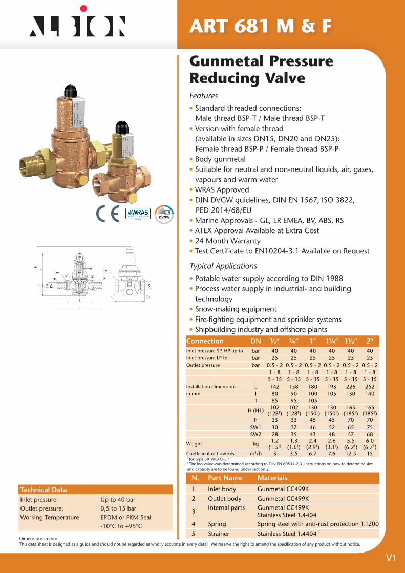
Features• Standard threaded connections: Male thread BSP-T / Male thread BSP-T• Version with female thread (available in sizes DN15, DN20 and DN25): Female thread BSP-P / Female thread BSP-P• Body gunmetal• Suitable for neutral and non-neutral liquids, air, gases, vapours and warm water• WRAS Approved• DIN DVGW guidelines, DIN EN 1567, ISO 3822, PED 2014/68/EU• Marine Approvals - GL, LR EMEA, BV, ABS, RS• ATEX Approval Available at Extra Cost• 24 Month Warranty• Test Certificate to EN10204-3.1 Available on Request
ART 681 M & F
Typical Applications
• Potable water supply according to DIN 1988• Process water supply in industrial- and building technology• Snow-making equipment• Fire-fighting equipment and sprinkler systems• Shipbuilding industry and offshore plants
Technical DataInlet pressure: Up to 40 barOutlet pressure: 0,5 to 15 barWorking Temperature EPDM or FKM Seal -10°C to +95°C
N. Part Name Materials
1 Inlet body Gunmetal CC499K
2 Outlet body Gunmetal CC499K
3Internal parts Gunmetal CC499K
Stainless Steel 1.44044 Spring Spring steel with anti-rust protection 1.1200
5 Strainer Stainless Steel 1.4404
V1
Connection DN ½“ ¾“ 1“ 1¼“ 1½“ 2“Inlet pressure SP, HP up to bar 40 40 40 40 40 40Inlet pressure LP to bar 25 25 25 25 25 25Outlet pressure bar 0.5 - 2 0.5 - 2 0.5 - 2 0.5 - 2 0.5 - 2 0.5 - 2
1 - 8 1 - 8 1 - 8 1 - 8 1 - 8 1 - 85 - 15 5 - 15 5 - 15 5 - 15 5 - 15 5 - 15
Installation dimensions L 142 158 180 193 226 252in mm I 80 90 100 105 130 140
I1 85 95 105
H (H1) 102 (1281)
102 (1281)
130 (1501)
130 (1501)
165 (1851)
165 (1851)
h 33 33 45 45 70 70SW1 30 37 46 52 65 75SW2 28 35 43 48 57 68
Weight kg 1.2 (1.51)
1.3 (1.61)
2.4 (2.91)
2.6 (3.11)
5.5 (6.21)
6.0 (6.71)
Coefficient of flow kvs m3/h 3 3.5 6.7 7.6 12.5 151 for type 681mGFO-LP2 The kvs value was determined according to DIN EN 60534-2-3. Instructions on how to determine size and capacity are to be found under section 2.
Gunmetal Pressure Reducing Valve

Dimensions in mmThis data sheet is designed as a guide and should not be regarded as wholly accurate in every detail. We reserve the right to amend the specification of any product without notice.
ART 681 M & F
Option Materials Type Working Temp.
EPDM Ethylene propylene diene Elastomere moulded diaphragm and seals approvals according to drinking water directive –10°C to +95°C
Against surcharge
FKM Fluorocarbon Elastomere moulded diaphragm and seals –10°C to +95°C
Valve version
m with diaphragmHigh-quality, heat-resistant moulded elastomere, fabric-reinforced diaphragm. Pressure adjustment by means of non-rising spindle. Valve insert with balanced single seat valve completely made of stainless steel.
Complete valve insert SP/HP (order code: 681 Insert-DN..-seal) available as replacement part can be exchanged without removing the valve.
Complete valve insert LP (order code: 681 LP Insert-DN..-seal) available as replacement part can be exchanged without removing the valve.
Built-in dirt trap made of stainless steel.
Mesh size: DN 15 to DN 32DN 40 and DN 50
0,60 mm0,75 mm
Medium
GF gaseous and liquidfor water and distilled water, neutral and non-sticking liquids, compressed air and neutral gases; optionally with FPM elastomere seals for non-neutral media i.e. oils, fuels, oil-laden compressed air etc.
Type of lifting mechanism
O without lifting device
SP Standard version Inlet pressure: up to 40 bar Outlet pressure: from 1 to 8 bar
HP High-pressure version Inlet pressure: up to 40 bar Outlet pressure: from 5 to 15 bar
LP Low-pressure version Inlet pressure: up to 25 bar Outlet pressure: from 0,5 to 2 bar
Fixed setting at a required outlet pressure against surcharge.
Outlet pressure ranges
Seat-Seal/Diaphragm Options
V1

Dimensions in mmThis data sheet is designed as a guide and should not be regarded as wholly accurate in every detail. We reserve the right to amend the specification of any product without notice.
Capacity charts
ART 681 M & F
Dimensioning by pressure loss on the outlet pressure side
V1
Art 681 M & F
Flow chart water
Flo
w r
ate
V in
[m
³/h]
Pressure drop delta p [bar]Dimensioning by flow velocity
For Liquids: With help of the chart you can determine the nominal diameter (DN) for a given flow volume V (m³/h). According to DVGW-guidelines (DIN 1988) a flow velocity of 2 m/s in domestic water supply systems should not be exceeded. For compressed air and other gaseous media: The usual flow velocity for compressed air is 10 - 20 m/s. For gaseous media the flow volume V should always be shown in actual cubic meters/hour. If the flow volume is given in standard cubic meters, these should be converted into actual cubic meters before using the diagram.
Actual cubic meters are based on the prevailing pressure of the medium on the outlet side of the pressure reducer.
Flo
w v
elo
city
c [
m/s
]
Flow volume V [m3/h]
Dimensions in mmThis data sheet is designed as a guide and should not be regarded as wholly accurate in every detail. We reserve the right to amend the specification of any product without notice.
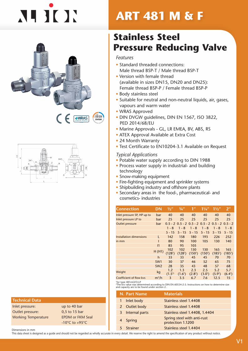
Features• Standard threaded connections: Male thread BSP-T / Male thread BSP-T• Version with female thread (available in sizes DN15, DN20 and DN25): Female thread BSP-P / Female thread BSP-P• Body stainless steel• Suitable for neutral and non-neutral liquids, air, gases, vapours and warm water• WRAS Approved• DIN DVGW guidelines, DIN EN 1567, ISO 3822, PED 2014/68/EU• Marine Approvals - GL, LR EMEA, BV, ABS, RS• ATEX Approval Available at Extra Cost• 24 Month Warranty• Test Certificate to EN10204-3.1 Available on Request
ART 481 M & F
Typical Applications• Potable water supply according to DIN 1988• Process water supply in industrial- and building technology• Snow-making equipment• Fire-fighting equipment and sprinkler systems• Shipbuilding industry and offshore plants• Secondary areas in the food-, pharmaceutical- and cosmetics- industries
Technical DataInlet pressure: up to 40 barOutlet pressure: 0,5 to 15 barWorking Temperature EPDM or FKM Seal -10°C to +95°C
N. Part Name Materials
1 Inlet body Stainless steel 1.4408
2 Outlet body Stainless steel 1.4408
3 Internal parts Stainless steel 1.4408, 1.4404
4 SpringSpring steel with anti-rust protection 1.1200
5 Strainer Stainless steel 1.4404
V1
Stainless Steel Pressure Reducing Valve
Connection DN ½“ ¾“ 1“ 1¼“ 1½“ 2“Inlet pressure SP, HP up to bar 40 40 40 40 40 40Inlet pressure LP to bar 25 25 25 25 25 25Outlet pressure bar 0.5 - 2 0.5 - 2 0.5 - 2 0.5 - 2 0.5 - 2 0.5 - 2
1 - 8 1 - 8 1 - 8 1 - 8 1 - 8 1 - 85 - 15 5 - 15 5 - 15 5 - 15 5 - 15 5 - 15
Installation dimensions L 142 158 180 193 226 252in mm I 80 90 100 105 130 140
I1 85 95 105
H (H1) 102 (1281)
102 (1281)
130 (1501)
130 (1501)
165 (1851)
165 (1851)
h 33 33 45 45 70 70SW1 30 37 46 52 65 75SW2 28 35 43 48 57 68
Weight kg 1.2 (1.51)
1.3 (1.61)
2.3 (2.81)
2.5 (3.01)
5.2 (5.91)
5.7 (6.41)
Coefficient of flow kvs m3/h 3 3.5 6.7 7.6 12.5 151for type 481mGFO-LP2The kvs value was determined according to DIN EN 60534-2-3. Instructions on how to determine size and capacity are to be found under section 2.

Dimensions in mmThis data sheet is designed as a guide and should not be regarded as wholly accurate in every detail. We reserve the right to amend the specification of any product without notice.
ART 481 M & F
Option Materials Type Working Temp.
EPDM Ethylene propylene diene Elastomere moulded diaphragm and seals approvals according to drinking water directive –10°C to +95°C
Against surcharge
FKM Fluorocarbon Elastomere moulded diaphragm and seals –10°C to +95°C
Valve version
m with diaphragmHigh-quality, heat-resistant moulded elastomere, fabric-reinforced diaphragm. Pressure adjustment by means of non-rising spindle. Valve insert with balanced single seat valve completely made of stainless steel.
Complete valve insert SP/HP (order code: 481 Insert-DN..-seal) available as replacement part can be exchanged without removing the valve.
Complete valve insert LP (order code: 481 LP Insert-DN..-seal) available as replacement part can be exchanged without removing the valve.
Built-in dirt trap made of stainless steel.
Mesh size: DN 15 to DN 32DN 40 and DN 50
0,60 mm0,75 mm
Medium
GF gaseous and liquidfor water and distilled water, neutral and non-sticking liquids, compressed air and neutral gases; optionally with FPM elastomere seals for non-neutral media i.e. oils, fuels, oil-laden compressed air etc.
Type of lifting mechanism
O without lifting device
SP Standard version Inlet pressure: up to 40 bar Outlet pressure: from 1 to 8 bar
HP High-pressure version Inlet pressure: up to 40 bar Outlet pressure: from 5 to 15 bar
LP Low-pressure version Inlet pressure: up to 25 bar Outlet pressure: from 0,5 to 2 bar
Fixed setting at a required outlet pressure against surcharge.
Outlet pressure ranges
Seat-Seal/Diaphragm Options
V1
Dimensions in mmThis data sheet is designed as a guide and should not be regarded as wholly accurate in every detail. We reserve the right to amend the specification of any product without notice.
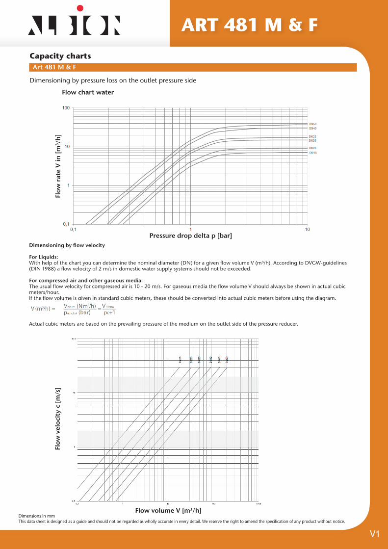
Capacity charts
ART 481 M & F
Dimensioning by pressure loss on the outlet pressure side
V1
Art 481 M & F
Flow chart water
Flo
w r
ate
V in
[m
³/h]
Pressure drop delta p [bar]Dimensioning by flow velocity
For Liquids: With help of the chart you can determine the nominal diameter (DN) for a given flow volume V (m³/h). According to DVGW-guidelines (DIN 1988) a flow velocity of 2 m/s in domestic water supply systems should not be exceeded. For compressed air and other gaseous media: The usual flow velocity for compressed air is 10 - 20 m/s. For gaseous media the flow volume V should always be shown in actual cubic meters/hour. If the flow volume is given in standard cubic meters, these should be converted into actual cubic meters before using the diagram.
Actual cubic meters are based on the prevailing pressure of the medium on the outlet side of the pressure reducer.
Flo
w v
elo
city
c [
m/s
]
Flow volume V [m3/h]

Dimensions in mmThis data sheet is designed as a guide and should not be regarded as wholly accurate in every detail. We reserve the right to amend the specification of any product without notice.
1. Safety• Only use the valve; - for the intended purpose - in satisfactory condition - with respect for safety and potential hazards.• Always observe the installation instructions;
• Faults that may impair safety must be addressed immediately;
• The valves are exclusively intended for the application area stated in these installation instructions. Any other or further use is not valid as the intended use;
• The manufacturer’s warranty shall be null and void if the sealed cover is removed;
• All assembly work is to be carried out by authorised specialist staff.
2. General NotesSafety valves are high-quality fittings which require a particularly careful handling.
The sealing surfaces are precision-machined at the seat and cone to attain the required tightness. Always avoid the penetration of foreign particles into the valve during assembly and during the operation. The tightness of a safety valve can be impaired when using hemp, PTFE tape and welding beads, amongst other things. Also rough handling of the finished valve during storage, transport and assembly can result in a safety valve leaking. If the safety valves are painted, make sure that the sliding parts do not come into contact with the paint.
3. Range of ApplicationFor details on the range of application of the individual versions please refer to the datasheets of the manufacturer.
4. Installation and AssemblySpring-loaded safety valves are to be installed with the spring bonnet pointing vertically upward in line with the direction of the arrow. To ensure satisfactory operation of the safety valves they must be installed in such a way that the safety valve is not exposed to any impermissible static, dynamic or thermal loads.Appropriate protection devices must be applied if the medium that discharges upon actuation of the valve can lead to direct or indirect hazards to people or the environment. Always pay attention to possible fumes discharging from the relief bores in the spring bonnet.
Fig. a
SupplySupply connection pieces for safety valves are to be kept as short as possible and are to be designed in such a way that there can be no pressure loss greater than 3% (Max.) of the response pressure.Removal of condensate dischargeIn the event of possible condensation the pipes or the valves themselves must be fitted at their lowest point with a continuously operating condensate discharge device. Hazard-free removal of the condensate or medium discharge must be ensured. The body, pipes and silencers must be protected against freezing.Blowing-off pipe / backpressureThe blow-off pipe of the safety valves must be designed to ensure that the required mass flow can be discharged pressure-free during the blowing-off process.
5. Operation/MaintenanceSafety valves are the ultimate safety device for the tank or system. They must be able to prevent impermissible overpressure even when all other upstream control and monitoring equipment fail. To ensure these characteristics safety valves require maintenance, just like any other technical device. The maintenance intervals are determined by the operator in depending upon the operating conditions. The operating pressure of the plant is to be at least 5 % lower than the closing pressure of the safety valve. In this way, the valve can satisfactorily close again after blowing off.In the event of minor leaks, which may be caused by contamination between the sealing surfaces, the valve can be made to blow off through lifting, for cleaning purposes. If this does not remove the leak, the sealing surface is probably damaged and this can only be repaired at our factory or by authorised specialists. Lifting is by actuating the lifting lever on the upper part of the valve (Fig. a). For delivery purposes the lifting lever is tied by means of a strap which has to be removed for actuating the lifting device.Prior to removal make sure that the safety valve is not under pressure.
Lifting for maintenance purposesIt is recommended and in some plant specific situations mandatory to manually “blow off“ the valve by lifting the seal off the seat with the use of the lifting lever (fig a), in order to ensure correct functioning of the safety valve.The line pressure must be ≥ 85% of the set pressure before the lifting the lever. The lifting lever is NOT to be operated when the pressure is zero.
Assembly & Maintenance Instructions - ART 642 & 645
V1
Dimensions in mmThis data sheet is designed as a guide and should not be regarded as wholly accurate in every detail. We reserve the right to amend the specification of any product without notice.
6. Dismantling the FittingIn addition to the general installation instructions it must be ensured that the system is made pressure free prior to disassembly of the safety valve.
7. RepairsRepair work on safety valves is only to be carried out by Goetze KG Armaturen or by officially approved specialist workshops authorised by Goetze KG Armaturen using original spare parts only.
8. WarrantyEvery valve is tested prior to leaving the factory. We grant a warranty for our products which entails a free of charge repair of any parts that are returned and verified as being prematurely unsuitable for use due to defective material or manufacturing. We shall not assume any liability for any damage or other such obligations. If the seal is damaged due to any incorrect handling of or installation, non-observance of these operating and maintenance instructions, contamination or normal wear, warranty claims shall be null and void.
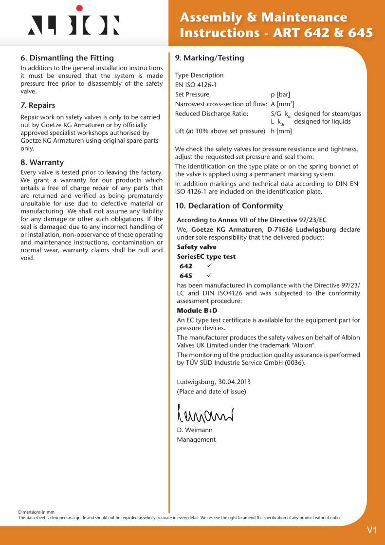
9. Marking/Testing
10. Declaration of Conformity
Assembly & Maintenance Instructions - ART 642 & 645
We check the safety valves for pressure resistance and tightness, adjust the requested set pressure and seal them.The identification on the type plate or on the spring bonnet of the valve is applied using a permanent marking system.In addition markings and technical data according to DIN EN ISO 4126-1 are included on the identification plate.
Type DescriptionEN ISO 4126-1Set Pressure Narrowest cross-section of flow:Reduced Discharge Ratio:
Lift (at 10% above set pressure)
p [bar]A [mm2]S/G kdr designed for steam/gas L kdr designed for liquidsh [mm]
According to Annex VII of the Directive 97/23/ECWe, Goetze KG Armaturen, D-71636 Ludwigsburg declare under sole responsibility that the delivered poduct:Safety valve Series EC type test 642 ü
645 ü
has been manufactured in compliance with the Directive 97/23/EC and DIN ISO4126 and was subjected to the conformity assessment procedure:Module B+DAn EC type test certificate is available for the equipment part for pressure devices.The manufacturer produces the safety valves on behalf of Albion Valves UK Limited under the trademark "Albion".The monitoring of the production quality assurance is performed by TÜV SÜD Industrie Service GmbH (0036).
Ludwigsburg, 30.04.2013(Place and date of issue)
D. WeimannManagement
V1

Distributor
Certificate No. 1437A
Certificate No. 1437B


