PRESSURE AND FLUID STATICS T - kau 3.pdf · PRESSURE AND FLUID STATICS This chapter deals with...
56
PRESSURE AND FLUID STATICS T his chapter deals with forces applied by fluids at rest or in rigid-body motion. The fluid property responsible for those forces is pressure, which is a normal force exerted by a fluid per unit area. We start this chapter with a detailed discussion of pressure, including absolute and gage pressures, the pressure at a point, the variation of pressure with depth in a gravitational field, the manometer, the barometer, and pressure measure- ment devices. This is followed by a discussion of the hydrostatic forces applied on submerged bodies with plane or curved surfaces. We then con- sider the buoyant force applied by fluids on submerged or floating bodies, and discuss the stability of such bodies. Finally, we apply Newton’s second law of motion to a body of fluid in motion that acts as a rigid body and ana- lyze the variation of pressure in fluids that undergo linear acceleration and in rotating containers. This chapter makes extensive use of force balances for bodies in static equilibrium, and it will be helpful if the relevant topics from statics are first reviewed. 65 CHAPTER 3 OBJECTIVES When you finish reading this chapter, you should be able to ■ Determine the variation of pressure in a fluid at rest ■ Calculate the forces exerted by a fluid at rest on plane or curved submerged surfaces ■ Analyze the rigid-body motion of fluids in containers during linear acceleration or rotation cen72367_ch03.qxd 10/29/04 2:21 PM Page 65
-
Upload
truongtuyen -
Category
Documents
-
view
263 -
download
0
Transcript of PRESSURE AND FLUID STATICS T - kau 3.pdf · PRESSURE AND FLUID STATICS This chapter deals with...

P R E S S U R E A N D F L U I D S TAT I C S
This chapter deals with forces applied by fluids at rest or in rigid-body
motion. The fluid property responsible for those forces is pressure,
which is a normal force exerted by a fluid per unit area. We start this
chapter with a detailed discussion of pressure, including absolute and gage
pressures, the pressure at a point, the variation of pressure with depth in a
gravitational field, the manometer, the barometer, and pressure measure-
ment devices. This is followed by a discussion of the hydrostatic forces
applied on submerged bodies with plane or curved surfaces. We then con-
sider the buoyant force applied by fluids on submerged or floating bodies,
and discuss the stability of such bodies. Finally, we apply Newton’s second
law of motion to a body of fluid in motion that acts as a rigid body and ana-
lyze the variation of pressure in fluids that undergo linear acceleration and
in rotating containers. This chapter makes extensive use of force balances
for bodies in static equilibrium, and it will be helpful if the relevant topics
from statics are first reviewed.
65
CHAPTER
3OBJECTIVES
When you finish reading this chapter, you
should be able to
� Determine the variation of
pressure in a fluid at rest
� Calculate the forces exerted by a
fluid at rest on plane or curved
submerged surfaces
� Analyze the rigid-body motion of
fluids in containers during linear
acceleration or rotation
cen72367_ch03.qxd 10/29/04 2:21 PM Page 65
3–1 � PRESSURE
Pressure is defined as a normal force exerted by a fluid per unit area. We
speak of pressure only when we deal with a gas or a liquid. The counterpart
of pressure in solids is normal stress. Since pressure is defined as force per
unit area, it has the unit of newtons per square meter (N/m2), which is called
a pascal (Pa). That is,
The pressure unit pascal is too small for pressures encountered in prac-
tice. Therefore, its multiples kilopascal (1 kPa � 103 Pa) and megapascal
(1 MPa � 106 Pa) are commonly used. Three other pressure units com-
monly used in practice, especially in Europe, are bar, standard atmosphere,
and kilogram-force per square centimeter:
Note the pressure units bar, atm, and kgf/cm2 are almost equivalent to each
other. In the English system, the pressure unit is pound-force per square
inch (lbf/in2, or psi), and 1 atm � 14.696 psi. The pressure units kgf/cm2
and lbf/in2 are also denoted by kg/cm2 and lb/in2, respectively, and they are
commonly used in tire gages. It can be shown that 1 kgf/cm2 � 14.223 psi.
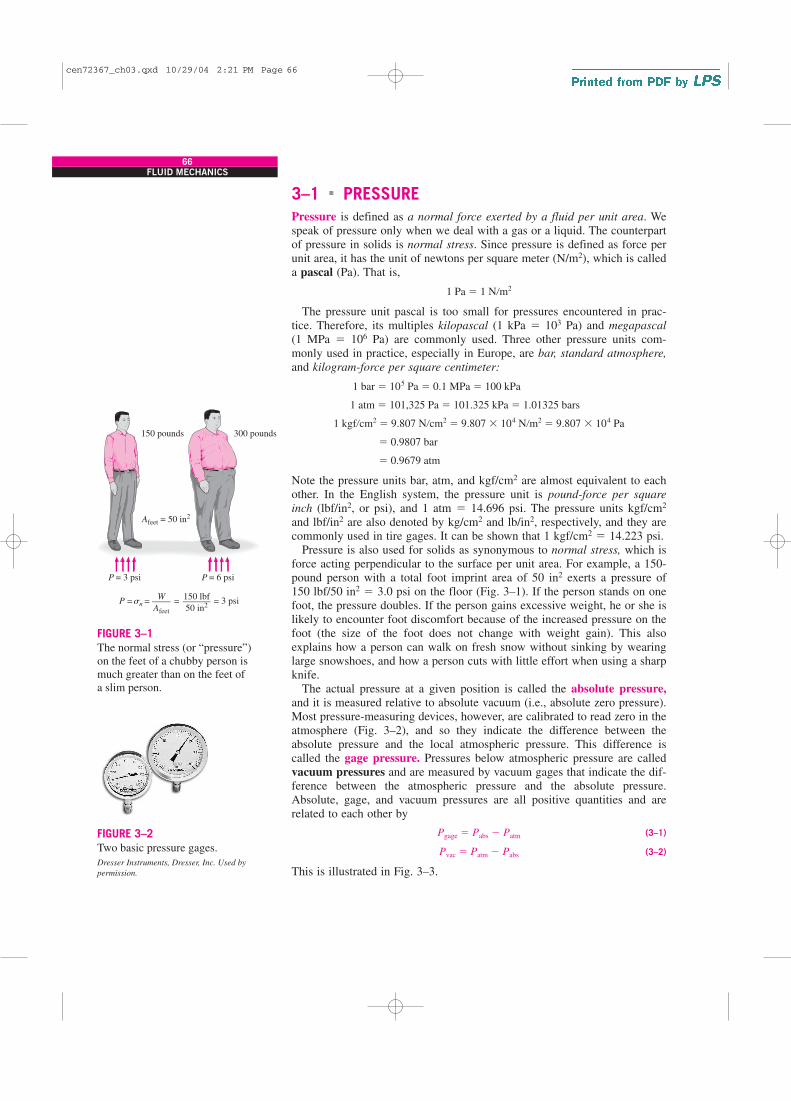
Pressure is also used for solids as synonymous to normal stress, which is
force acting perpendicular to the surface per unit area. For example, a 150-
pound person with a total foot imprint area of 50 in2 exerts a pressure of
150 lbf/50 in2 � 3.0 psi on the floor (Fig. 3–1). If the person stands on one
foot, the pressure doubles. If the person gains excessive weight, he or she is
likely to encounter foot discomfort because of the increased pressure on the
foot (the size of the foot does not change with weight gain). This also
explains how a person can walk on fresh snow without sinking by wearing
large snowshoes, and how a person cuts with little effort when using a sharp
knife.
The actual pressure at a given position is called the absolute pressure,
and it is measured relative to absolute vacuum (i.e., absolute zero pressure).
Most pressure-measuring devices, however, are calibrated to read zero in the
atmosphere (Fig. 3–2), and so they indicate the difference between the
absolute pressure and the local atmospheric pressure. This difference is
called the gage pressure. Pressures below atmospheric pressure are called
vacuum pressures and are measured by vacuum gages that indicate the dif-
ference between the atmospheric pressure and the absolute pressure.
Absolute, gage, and vacuum pressures are all positive quantities and are
related to each other by
(3–1)
(3–2)
This is illustrated in Fig. 3–3.
Pvac � Patm � Pabs
Pgage � Pabs � Patm
� 0.9679 atm
� 0.9807 bar
1 kgf�cm2� 9.807 N�cm2
� 9.807 � 104 N�m2� 9.807 � 104 Pa
1 atm � 101,325 Pa � 101.325 kPa � 1.01325 bars
1 bar � 105 Pa � 0.1 MPa � 100 kPa
1 Pa � 1 N�m2
66FLUID MECHANICS
150 pounds
Afeet = 50 in2
P = 3 psi P = 6 psi
300 pounds
W––––Afeet
150 lbf––––––50 in2
P = n = = 3 psi=s
FIGURE 3–1
The normal stress (or “pressure”)
on the feet of a chubby person is
much greater than on the feet of
a slim person.
FIGURE 3–2
Two basic pressure gages.
Dresser Instruments, Dresser, Inc. Used by
permission.
cen72367_ch03.qxd 10/29/04 2:21 PM Page 66

67CHAPTER 3
Absolute
vacuum
Absolute
vacuum
Pabs
Pvac
Patm
Patm
Patm
Pgage
Pabs
Pabs
= 0FIGURE 3–3
Absolute, gage, and vacuum pressures.
Like other pressure gages, the gage used to measure the air pressure in an
automobile tire reads the gage pressure. Therefore, the common reading of
32 psi (2.25 kgf/cm2) indicates a pressure of 32 psi above the atmospheric
pressure. At a location where the atmospheric pressure is 14.3 psi, for exam-
ple, the absolute pressure in the tire is 32 � 14.3 � 46.3 psi.
In thermodynamic relations and tables, absolute pressure is almost always
used. Throughout this text, the pressure P will denote absolute pressure
unless specified otherwise. Often the letters “a” (for absolute pressure) and
“g” (for gage pressure) are added to pressure units (such as psia and psig) to
clarify what is meant.
EXAMPLE 3–1 Absolute Pressure of a Vacuum Chamber
A vacuum gage connected to a chamber reads 5.8 psi at a location where
the atmospheric pressure is 14.5 psi. Determine the absolute pressure in the
chamber.
SOLUTION The gage pressure of a vacuum chamber is given. The absolute
pressure in the chamber is to be determined.
Analysis The absolute pressure is easily determined from Eq. 3–2 to be
Discussion Note that the local value of the atmospheric pressure is used
when determining the absolute pressure.
Pressure at a PointPressure is the compressive force per unit area, and it gives the impression
of being a vector. However, pressure at any point in a fluid is the same in all
directions. That is, it has magnitude but not a specific direction, and thus it
is a scalar quantity. This can be demonstrated by considering a small
wedge-shaped fluid element of unit length (into the page) in equilibrium, as
shown in Fig. 3–4. The mean pressures at the three surfaces are P1, P2, and
P3, and the force acting on a surface is the product of mean pressure and the
Pabs � Patm � Pvac � 14.5 � 5.8 � 8.7 psi
cen72367_ch03.qxd 10/29/04 2:21 PM Page 67

surface area. From Newton’s second law, a force balance in the x- and z-
directions gives
(3–3a)
(3–3b)
where r is the density and W � mg � rg �x �z/2 is the weight of the fluid
element. Noting that the wedge is a right triangle, we have �x � l cos u and
�z � l sin u. Substituting these geometric relations and dividing Eq. 3–3a
by �z and Eq. 3–3b by �x gives
(3–4a)
(3–4b)
The last term in Eq. 3–4b drops out as �z → 0 and the wedge becomes
infinitesimal, and thus the fluid element shrinks to a point. Then combining
the results of these two relations gives
(3–5)
regardless of the angle u. We can repeat the analysis for an element in the
xz-plane and obtain a similar result. Thus we conclude that the pressure at a
point in a fluid has the same magnitude in all directions. It can be shown in
the absence of shear forces that this result is applicable to fluids in motion
as well as fluids at rest.
Variation of Pressure with DepthIt will come as no surprise to you that pressure in a fluid at rest does not
change in the horizontal direction. This can be shown easily by considering
a thin horizontal layer of fluid and doing a force balance in any horizontal
direction. However, this is not the case in the vertical direction in a gravity
field. Pressure in a fluid increases with depth because more fluid rests on
P1 � P2 � P3 � P
P2 � P3 �1
2 rg �z � 0
P1 � P3 � 0
a Fz � maz � 0: P2 �x � P3l cos u �1
2 rg �x �z � 0
a Fx � max � 0: P1 �z � P3l sin u � 0
68FLUID MECHANICS
P2 �x
P3l
P1 �z
�x
(�y = 1)
z�
z
x
l
u
u
FIGURE 3–4
Forces acting on a wedge-shaped fluid
element in equilibrium.
cen72367_ch03.qxd 10/29/04 2:21 PM Page 68

deeper layers, and the effect of this “extra weight” on a deeper layer is bal-
anced by an increase in pressure (Fig. 3–5).
To obtain a relation for the variation of pressure with depth, consider a
rectangular fluid element of height �z, length �x, and unit depth (into the
page) in equilibrium, as shown in Fig. 3–6. Assuming the density of the
fluid r to be constant, a force balance in the vertical z-direction gives
(3–6)
where W � mg � rg �x �z is the weight of the fluid element. Dividing by
�x and rearranging gives
(3–7)
where gs � rg is the specific weight of the fluid. Thus, we conclude that the
pressure difference between two points in a constant density fluid is propor-
tional to the vertical distance �z between the points and the density r of the
fluid. In other words, pressure in a fluid increases linearly with depth. This
is what a diver experiences when diving deeper in a lake. For a given fluid,
the vertical distance �z is sometimes used as a measure of pressure, and it is
called the pressure head.
We also conclude from Eq. 3–7 that for small to moderate distances, the
variation of pressure with height is negligible for gases because of their low
density. The pressure in a tank containing a gas, for example, can be consid-
ered to be uniform since the weight of the gas is too small to make a signif-
icant difference. Also, the pressure in a room filled with air can be assumed
to be constant (Fig. 3–7).
If we take point 1 to be at the free surface of a liquid open to the atmo-
sphere (Fig. 3–8), where the pressure is the atmospheric pressure Patm, then
the pressure at a depth h from the free surface becomes
(3–8)
Liquids are essentially incompressible substances, and thus the variation
of density with depth is negligible. This is also the case for gases when the
elevation change is not very large. The variation of density of liquids or
gases with temperature can be significant, however, and may need to be
considered when high accuracy is desired. Also, at great depths such as
those encountered in oceans, the change in the density of a liquid can be
significant because of the compression by the tremendous amount of liquid
weight above.
The gravitational acceleration g varies from 9.807 m/s2 at sea level to
9.764 m/s2 at an elevation of 14,000 m where large passenger planes cruise.
This is a change of just 0.4 percent in this extreme case. Therefore, g can be
assumed to be constant with negligible error.
For fluids whose density changes significantly with elevation, a relation
for the variation of pressure with elevation can be obtained by dividing Eq.
3–6 by �x �z, and taking the limit as �z → 0. It gives
(3–9)
The negative sign is due to our taking the positive z direction to be upward
so that dP is negative when dz is positive since pressure decreases in an
upward direction. When the variation of density with elevation is known,
dP
dz� �rg
P � Patm � rgh or Pgage � rgh
�P � P2 � P1 � rg �z � gs �z
a Fz � maz � 0: P2 �x � P1 �x � rg �x �z � 0
69CHAPTER 3
Pgage
FIGURE 3–5
The pressure of a fluid at rest
increases with depth (as a result
of added weight).
P2
W
P1
x
0
z
z
x
�
�
FIGURE 3–6
Free-body diagram of a rectangular
fluid element in equilibrium.
Ptop
= 1 atm
AIR
(A 5-m-high room)
Pbottom
= 1.006 atm
FIGURE 3–7
In a room filled with a gas, the
variation of pressure with height
is negligible.
cen72367_ch03.qxd 10/29/04 2:21 PM Page 69

the pressure difference between points 1 and 2 can be determined by inte-
gration to be
(3–10)
For constant density and constant gravitational acceleration, this relation
reduces to Eq. 3–7, as expected.
Pressure in a fluid at rest is independent of the shape or cross section of
the container. It changes with the vertical distance, but remains constant in
other directions. Therefore, the pressure is the same at all points on a hori-
zontal plane in a given fluid. The Dutch mathematician Simon Stevin
(1548–1620) published in 1586 the principle illustrated in Fig. 3–9. Note
that the pressures at points A, B, C, D, E, F, and G are the same since they
are at the same depth, and they are interconnected by the same static fluid.
However, the pressures at points H and I are not the same since these two
points cannot be interconnected by the same fluid (i.e., we cannot draw a
curve from point I to point H while remaining in the same fluid at all
times), although they are at the same depth. (Can you tell at which point the
pressure is higher?) Also, the pressure force exerted by the fluid is always
normal to the surface at the specified points.
A consequence of the pressure in a fluid remaining constant in the hori-
zontal direction is that the pressure applied to a confined fluid increases the
pressure throughout by the same amount. This is called Pascal’s law, after
Blaise Pascal (1623–1662). Pascal also knew that the force applied by a
fluid is proportional to the surface area. He realized that two hydraulic
cylinders of different areas could be connected, and the larger could be used
to exert a proportionally greater force than that applied to the smaller. “Pas-
cal’s machine” has been the source of many inventions that are a part of our
daily lives such as hydraulic brakes and lifts. This is what enables us to lift
�P � P2 � P1 � ��2
1
rg dz
70FLUID MECHANICS
P1 = Patm
P2 = Patm + rgh
h
1
2
FIGURE 3–8
Pressure in a liquid at rest increases
linearly with distance from the free
surface.
h
A B C D E
Water
Mercury
F G
IH
Patm
PA = PB = PC = PD = PE = PF = PG = Patm + rgh
PH ≠ PI
FIGURE 3–9
The pressure is the same at all points on a horizontal plane in a given fluid regardless of geometry, provided that the
points are interconnected by the same fluid.
cen72367_ch03.qxd 10/29/04 2:21 PM Page 70

a car easily by one arm, as shown in Fig. 3–10. Noting that P1 � P2 since
both pistons are at the same level (the effect of small height differences is
negligible, especially at high pressures), the ratio of output force to input
force is determined to be
(3–11)
The area ratio A2 /A1 is called the ideal mechanical advantage of the hydraulic
lift. Using a hydraulic car jack with a piston area ratio of A2 /A1 � 10, for
example, a person can lift a 1000-kg car by applying a force of just 100 kgf
(� 908 N).
3–2 � THE MANOMETER
We notice from Eq. 3–7 that an elevation change of �z in a fluid at rest cor-
responds to �P/rg, which suggests that a fluid column can be used to mea-
sure pressure differences. A device based on this principle is called a
manometer, and it is commonly used to measure small and moderate pres-
sure differences. A manometer mainly consists of a glass or plastic U-tube
containing one or more fluids such as mercury, water, alcohol, or oil. To
keep the size of the manometer to a manageable level, heavy fluids such as
mercury are used if large pressure differences are anticipated.
Consider the manometer shown in Fig. 3–11 that is used to measure the
pressure in the tank. Since the gravitational effects of gases are negligible,
the pressure anywhere in the tank and at position 1 has the same value. Fur-
thermore, since pressure in a fluid does not vary in the horizontal direction
within a fluid, the pressure at point 2 is the same as the pressure at point 1,
P2 � P1.
The differential fluid column of height h is in static equilibrium, and it is
open to the atmosphere. Then the pressure at point 2 is determined directly
from Eq. 3–8 to be
(3–12)
where r is the density of the fluid in the tube. Note that the cross-sectional
area of the tube has no effect on the differential height h, and thus the pres-
sure exerted by the fluid. However, the diameter of the tube should be large
enough (more than a few millimeters) to ensure that the surface tension
effect and thus the capillary rise is negligible.
EXAMPLE 3–2 Measuring Pressure with a Manometer
A manometer is used to measure the pressure in a tank. The fluid used has
a specific gravity of 0.85, and the manometer column height is 55 cm, as
shown in Fig. 3–12. If the local atmospheric pressure is 96 kPa, determine
the absolute pressure within the tank.
SOLUTION The reading of a manometer attached to a tank and the
atmospheric pressure are given. The absolute pressure in the tank is to be
determined.
Assumptions The fluid in the tank is a gas whose density is much lower
than the density of manometer fluid.
P2 � Patm � rgh
P1 � P2 → F1
A1
�F2
A2
→ F2
F1
�A2
A1
71CHAPTER 3
F1 = P1A1
1 2A1P1
F2 = P2 A2
A2P2
FIGURE 3–10
Lifting of a large weight by
a small force by the application
of Pascal’s law.
Gash
1 2
FIGURE 3–11
The basic manometer.
P
SG
= ?h = 55 cm
= 0.85
Patm
= 96 kPa
FIGURE 3–12
Schematic for Example 3–2.
cen72367_ch03.qxd 10/29/04 2:21 PM Page 71

Properties The specific gravity of the manometer fluid is given to be 0.85.
We take the standard density of water to be 1000 kg/m3.
Analysis The density of the fluid is obtained by multiplying its specific
gravity by the density of water, which is taken to be 1000 kg/m3:
Then from Eq. 3–12,
Discussion Note that the gage pressure in the tank is 4.6 kPa.
Many engineering problems and some manometers involve multiple
immiscible fluids of different densities stacked on top of each other. Such
systems can be analyzed easily by remembering that (1) the pressure change
across a fluid column of height h is �P � rgh, (2) pressure increases down-
ward in a given fluid and decreases upward (i.e., Pbottom � Ptop), and (3) two
points at the same elevation in a continuous fluid at rest are at the same
pressure.
The last principle, which is a result of Pascal’s law, allows us to “jump”
from one fluid column to the next in manometers without worrying about
pressure change as long as we don’t jump over a different fluid, and the
fluid is at rest. Then the pressure at any point can be determined by starting
with a point of known pressure and adding or subtracting rgh terms as we
advance toward the point of interest. For example, the pressure at the bot-
tom of the tank in Fig. 3–13 can be determined by starting at the free sur-
face where the pressure is Patm, moving downward until we reach point 1 at
the bottom, and setting the result equal to P1. It gives
In the special case of all fluids having the same density, this relation reduces
to Eq. 3–12, as expected.
Manometers are particularly well-suited to measure pressure drops across
a horizontal flow section between two specified points due to the presence
of a device such as a valve or heat exchanger or any resistance to flow. This
is done by connecting the two legs of the manometer to these two points, as
shown in Fig. 3–14. The working fluid can be either a gas or a liquid whose
density is r1. The density of the manometer fluid is r2, and the differential
fluid height is h.
A relation for the pressure difference P1 � P2 can be obtained by starting
at point 1 with P1, moving along the tube by adding or subtracting the rgh
terms until we reach point 2, and setting the result equal to P2:
(3–13)
Note that we jumped from point A horizontally to point B and ignored the
part underneath since the pressure at both points is the same. Simplifying,
(3–14)P1 � P2 � (r2 � r1)gh
P1 � r1g(a � h) � r2gh � r1ga � P2
Patm � r1gh1 � r2gh2 � r3gh3 � P1
� 100.6 kPa
� 96 kPa � (850 kg�m3)(9.81 m�s2)(0.55 m)a 1 N
1 kg � m�s2b a 1 kPa
1000 N�m2b
P � Patm � rgh
r � SG (rH2O) � (0.85)(1000 kg�m3) � 850 kg�m3
72FLUID MECHANICS
Patm
1h3
h2
h1
Fluid 2
Fluid 1
Fluid 3
FIGURE 3–13
In stacked-up fluid layers, the pressure
change across a fluid layer of density
r and height h is rgh.
a
hr1
A B
Fluid
A flow section
or flow device
1 2
r2
FIGURE 3–14
Measuring the pressure drop across a
flow section or a flow device by a
differential manometer.
cen72367_ch03.qxd 10/29/04 2:21 PM Page 72

Note that the distance a has no effect on the result, but must be included in
the analysis. Also, when the fluid flowing in the pipe is a gas, then r1 r2
and the relation in Eq. 3–14 simplifies to P1 � P2 � r2gh.
EXAMPLE 3–3 Measuring Pressure with a Multifluid Manometer
The water in a tank is pressurized by air, and the pressure is measured by a
multifluid manometer as shown in Fig. 3–15. The tank is located on a moun-
tain at an altitude of 1400 m where the atmospheric pressure is 85.6 kPa.
Determine the air pressure in the tank if h1 � 0.1 m, h2 � 0.2 m, and h3 �
0.35 m. Take the densities of water, oil, and mercury to be 1000 kg/m3,
850 kg/m3, and 13,600 kg/m3, respectively.
SOLUTION The pressure in a pressurized water tank is measured by a multi-
fluid manometer. The air pressure in the tank is to be determined.
Assumption The air pressure in the tank is uniform (i.e., its variation with
elevation is negligible due to its low density), and thus we can determine the
pressure at the air–water interface.
Properties The densities of water, oil, and mercury are given to be
1000 kg/m3, 850 kg/m3, and 13,600 kg/m3, respectively.
Analysis Starting with the pressure at point 1 at the air–water interface,
moving along the tube by adding or subtracting the rgh terms until we reach
point 2, and setting the result equal to Patm since the tube is open to the
atmosphere gives
Solving for P1 and substituting,
Discussion Note that jumping horizontally from one tube to the next and
realizing that pressure remains the same in the same fluid simplifies the
analysis considerably. Also note that mercury is a toxic fluid, and mercury
manometers and thermometers are being replaced by ones with safer fluids
because of the risk of exposure to mercury vapor during an accident.
EXAMPLE 3–4 Analyzing a Multifluid Manometer with EES
Reconsider the multifluid manometer discussed in Example 3–3. Determine
the air pressure in the tank using EES. Also determine what the differential
fluid height h3 would be for the same air pressure if the mercury in the last
column were replaced by seawater with a density of 1030 kg/m3.
SOLUTION The pressure in a water tank is measured by a multifluid
manometer. The air pressure in the tank and the differential fluid height h3
if mercury is replaced by seawater are to be determined using EES.
� 130 kPa
� (850 kg�m3)(0.2 m)]a 1 N
1 kg � m�s2b a 1 kPa
1000 N�m2b
� 85.6 kPa � (9.81 m�s2)[(13,600 kg�m3)(0.35 m) � (1000 kg�m3)(0.1 m)
� Patm � g(rmercuryh3 � rwaterh1 � roilh2)
P1 � Patm � rwatergh1 � roilgh2 � rmercurygh3
P1 � rwatergh1 � roilgh2 � rmercurygh3 � Patm
73CHAPTER 3
h1
h2h3
Oil
Mercury
WATER
AIR
1
2
FIGURE 3–15
Schematic for Example 3–3; drawing
not to scale.
cen72367_ch03.qxd 10/29/04 2:21 PM Page 73

Analysis We start the EES program by double-clicking on its icon, open a
new file, and type the following on the blank screen that appears (we express
the atmospheric pressure in Pa for unit consistency):
Here P1 is the only unknown, and it is determined by EES to be
which is identical to the result obtained in Example 3–3. The height of the
fluid column h3 when mercury is replaced by seawater is determined easily by
replacing “h3=0.35” by “P1=129647” and “rm=13600” by “rm=1030,”
and clicking on the calculator symbol. It gives
Discussion Note that we used the screen like a paper pad and wrote down
the relevant information together with the applicable relations in an orga-
nized manner. EES did the rest. Equations can be written on separate lines
or on the same line by separating them by semicolons, and blank or com-
ment lines can be inserted for readability. EES makes it very easy to ask
“what if” questions and to perform parametric studies, as explained in
Appendix 3 on the DVD.
Other Pressure Measurement DevicesAnother type of commonly used mechanical pressure measurement device
is the Bourdon tube, named after the French engineer and inventor Eugene
Bourdon (1808–1884), which consists of a hollow metal tube bent like a
hook whose end is closed and connected to a dial indicator needle (Fig.
3–16). When the tube is open to the atmosphere, the tube is undeflected,
and the needle on the dial at this state is calibrated to read zero (gage pres-
sure). When the fluid inside the tube is pressurized, the tube stretches and
moves the needle in proportion to the pressure applied.
Electronics have made their way into every aspect of life, including pres-
sure measurement devices. Modern pressure sensors, called pressure trans-
ducers, use various techniques to convert the pressure effect to an electrical
effect such as a change in voltage, resistance, or capacitance. Pressure trans-
ducers are smaller and faster, and they can be more sensitive, reliable, and
precise than their mechanical counterparts. They can measure pressures
from less than a millionth of 1 atm to several thousands of atm.
A wide variety of pressure transducers is available to measure gage,
absolute, and differential pressures in a wide range of applications. Gage
pressure transducers use the atmospheric pressure as a reference by venting
the back side of the pressure-sensing diaphragm to the atmosphere, and they
give a zero signal output at atmospheric pressure regardless of altitude. The
absolute pressure transducers are calibrated to have a zero signal output at
full vacuum. Differential pressure transducers measure the pressure difference
h3 � 4.62 m
P1 � 129647 Pa � 130 kPa
P1�rw*g*h1�roil*g*h2�rm*g*h3�Patm
rw�1000; roil�850; rm�13600
h1�0.1; h2�0.2; h3�0.35
Patm�85600
g�9.81
74FLUID MECHANICS
C-type Spiral
Twisted tube
Tube cross section
Helical
FIGURE 3–16
Various types of Bourdon tubes used
to measure pressure.
cen72367_ch03.qxd 10/29/04 2:21 PM Page 74

between two locations directly instead of using two pressure transducers
and taking their difference.
Strain-gage pressure transducers work by having a diaphragm deflect
between two chambers open to the pressure inputs. As the diaphragm
stretches in response to a change in pressure difference across it, the strain
gage stretches and a Wheatstone bridge circuit amplifies the output. A
capacitance transducer works similarly, but capacitance change is measured
instead of resistance change as the diaphragm stretches.
Piezoelectric transducers, also called solid-state pressure transducers,
work on the principle that an electric potential is generated in a crystalline
substance when it is subjected to mechanical pressure. This phenomenon,
first discovered by brothers Pierre and Jacques Curie in 1880, is called the
piezoelectric (or press-electric) effect. Piezoelectric pressure transducers
have a much faster frequency response compared to the diaphragm units and
are very suitable for high-pressure applications, but they are generally not as
sensitive as the diaphragm-type transducers.
3–3 � THE BAROMETER AND ATMOSPHERIC PRESSURE
Atmospheric pressure is measured by a device called a barometer; thus, the
atmospheric pressure is often referred to as the barometric pressure.
The Italian Evangelista Torricelli (1608–1647) was the first to conclu-
sively prove that the atmospheric pressure can be measured by inverting a
mercury-filled tube into a mercury container that is open to the atmosphere,
as shown in Fig. 3–17. The pressure at point B is equal to the atmospheric
pressure, and the pressure at C can be taken to be zero since there is only
mercury vapor above point C and the pressure is very low relative to Patm
and can be neglected to an excellent approximation. Writing a force balance
in the vertical direction gives
(3–15)
where r is the density of mercury, g is the local gravitational acceleration,
and h is the height of the mercury column above the free surface. Note that
the length and the cross-sectional area of the tube have no effect on the
height of the fluid column of a barometer (Fig. 3–18).
A frequently used pressure unit is the standard atmosphere, which is
defined as the pressure produced by a column of mercury 760 mm in height
at 0°C (rHg � 13,595 kg/m3) under standard gravitational acceleration
(g � 9.807 m/s2). If water instead of mercury were used to measure the
standard atmospheric pressure, a water column of about 10.3 m would be
needed. Pressure is sometimes expressed (especially by weather forecasters)
in terms of the height of the mercury column. The standard atmospheric
pressure, for example, is 760 mmHg (29.92 inHg) at 0°C. The unit mmHg
is also called the torr in honor of Torricelli. Therefore, 1 atm � 760 torr
and 1 torr � 133.3 Pa.
The standard atmospheric pressure Patm changes from 101.325 kPa at sea
level to 89.88, 79.50, 54.05, 26.5, and 5.53 kPa at altitudes of 1000, 2000,
5000, 10,000, and 20,000 meters, respectively. The standard atmospheric
pressure in Denver (elevation � 1610 m), for example, is 83.4 kPa.
Patm � rgh
75CHAPTER 3
h
W rghA=
A
h
B
Mercury
C
Patm
FIGURE 3–17
The basic barometer.
A2
A1
A3
FIGURE 3–18
The length or the cross-sectional area
of the tube has no effect on the height
of the fluid column of a barometer,
provided that the tube diameter is
large enough to avoid surface tension
(capillary) effects.
cen72367_ch03.qxd 10/29/04 2:21 PM Page 75

76FLUID MECHANICS
Engine Lungs
FIGURE 3–19
At high altitudes, a car engine
generates less power and a person
gets less oxygen because of the
lower density of air.
Remember that the atmospheric pressure at a location is simply the
weight of the air above that location per unit surface area. Therefore, it
changes not only with elevation but also with weather conditions.
The decline of atmospheric pressure with elevation has far-reaching rami-
fications in daily life. For example, cooking takes longer at high altitudes
since water boils at a lower temperature at lower atmospheric pressures.
Nose bleeding is a common experience at high altitudes since the difference
between the blood pressure and the atmospheric pressure is larger in this
case, and the delicate walls of veins in the nose are often unable to with-
stand this extra stress.
For a given temperature, the density of air is lower at high altitudes, and
thus a given volume contains less air and less oxygen. So it is no surprise
that we tire more easily and experience breathing problems at high altitudes.
To compensate for this effect, people living at higher altitudes develop more
efficient lungs. Similarly, a 2.0-L car engine will act like a 1.7-L car engine
at 1500 m altitude (unless it is turbocharged) because of the 15 percent drop
in pressure and thus 15 percent drop in the density of air (Fig. 3–19). A fan
or compressor will displace 15 percent less air at that altitude for the same
volume displacement rate. Therefore, larger cooling fans may need to be
selected for operation at high altitudes to ensure the specified mass flow
rate. The lower pressure and thus lower density also affects lift and drag:
airplanes need a longer runway at high altitudes to develop the required lift,
and they climb to very high altitudes for cruising for reduced drag and thus
better fuel efficiency.
EXAMPLE 3–5 Measuring Atmospheric Pressure with a
Barometer
Determine the atmospheric pressure at a location where the barometric read-
ing is 740 mm Hg and the gravitational acceleration is g � 9.81 m/s2.
Assume the temperature of mercury to be 10°C, at which its density is
13,570 kg/m3.
SOLUTION The barometric reading at a location in height of mercury col-
umn is given. The atmospheric pressure is to be determined.
Assumptions The temperature of mercury is assumed to be 10°C.
Properties The density of mercury is given to be 13,570 kg/m3.
Analysis From Eq. 3–15, the atmospheric pressure is determined to be
Discussion Note that density changes with temperature, and thus this effect
should be considered in calculations.
EXAMPLE 3–6 Effect of Piston Weight on Pressure in a Cylinder
The piston of a vertical piston–cylinder device containing a gas has a mass
of 60 kg and a cross-sectional area of 0.04 m2, as shown in Fig. 3–20. The
� 98.5 kPa
� (13,570 kg�m3)(9.81 m�s2)(0.74 m)a 1 N
1 kg � m�s2b a 1 kPa
1000 N�m2b
Patm � rgh
cen72367_ch03.qxd 10/29/04 2:21 PM Page 76

77CHAPTER 3
A = 0.04 m2
P = ?
Patm
= 0.97 bar
m = 60 kgP
atm
W = mg
P
FIGURE 3–20
Schematic for Example 3–6, and the
free-body diagram of the piston.
Increasing salinityand density
Surface zone
Sun
r0 = 1040 kg/m3
H = 4 m
z
Gradient zone
Storage zone
1
2 FIGURE 3–21
Schematic for Example 3–7.
local atmospheric pressure is 0.97 bar, and the gravitational acceleration is
9.81 m/s2. (a) Determine the pressure inside the cylinder. (b) If some heat is
transferred to the gas and its volume is doubled, do you expect the pressure
inside the cylinder to change?
SOLUTION A gas is contained in a vertical cylinder with a heavy piston. The
pressure inside the cylinder and the effect of volume change on pressure are
to be determined.
Assumptions Friction between the piston and the cylinder is negligible.
Analysis (a) The gas pressure in the piston–cylinder device depends on the
atmospheric pressure and the weight of the piston. Drawing the free-body
diagram of the piston as shown in Fig. 3–20 and balancing the vertical
forces yield
Solving for P and substituting,
(b) The volume change will have no effect on the free-body diagram drawn in
part (a), and therefore the pressure inside the cylinder will remain the same.
Discussion If the gas behaves as an ideal gas, the absolute temperature
doubles when the volume is doubled at constant pressure.
EXAMPLE 3–7 Hydrostatic Pressure in a Solar Pond
with Variable Density
Solar ponds are small artificial lakes of a few meters deep that are used to
store solar energy. The rise of heated (and thus less dense) water to the sur-
face is prevented by adding salt at the pond bottom. In a typical salt gradi-
ent solar pond, the density of water increases in the gradient zone, as shown
in Fig. 3–21, and the density can be expressed as
where r0 is the density on the water surface, z is the vertical distance mea-
sured downward from the top of the gradient zone, and H is the thickness of
r � r0B1 � tan2ap4
z
Hb
� 1.12 bars
� 0.97 bar �(60 kg)(9.81 m�s2)
0.04 m2 a 1 N
1 kg � m�s2b a 1 bar
105 N�m2b
P � Patm �mg
A
PA � Patm A � W
cen72367_ch03.qxd 10/29/04 2:21 PM Page 77

the gradient zone. For H � 4 m, r0 � 1040 kg/m3, and a thickness of 0.8
m for the surface zone, calculate the gage pressure at the bottom of the gra-
dient zone.
SOLUTION The variation of density of saline water in the gradient zone of a
solar pond with depth is given. The gage pressure at the bottom of the gradi-
ent zone is to be determined.
Assumptions The density in the surface zone of the pond is constant.
Properties The density of brine on the surface is given to be 1040 kg/m3.
Analysis We label the top and the bottom of the gradient zone as 1 and 2,
respectively. Noting that the density of the surface zone is constant, the gage
pressure at the bottom of the surface zone (which is the top of the gradient
zone) is
since 1 kN/m2 � 1 kPa. The differential change in hydrostatic pressure
across a vertical distance of dz is given by
Integrating from the top of the gradient zone (point 1 where z � 0) to any
location z in the gradient zone (no subscript) gives
Performing the integration gives the variation of gage pressure in the gradi-
ent zone to be
Then the pressure at the bottom of the gradient zone (z � H � 4 m)
becomes
Discussion The variation of gage pressure in the gradient zone with depth is
plotted in Fig. 3–22. The dashed line indicates the hydrostatic pressure for
the case of constant density at 1040 kg/m3 and is given for reference. Note
that the variation of pressure with depth is not linear when density varies
with depth.
3–4 � INTRODUCTION TO FLUID STATICS
Fluid statics deals with problems associated with fluids at rest. The fluid
can be either gaseous or liquid. Fluid statics is generally referred to as
hydrostatics when the fluid is a liquid and as aerostatics when the fluid is a
gas. In fluid statics, there is no relative motion between adjacent fluid lay-
ers, and thus there are no shear (tangential) stresses in the fluid trying to
deform it. The only stress we deal with in fluid statics is the normal stress,
which is the pressure, and the variation of pressure is due only to the weight
of the fluid. Therefore, the topic of fluid statics has significance only in
� 54.0 kPa (gage)
P2 � 8.16 kPa � (1040 kg�m3)(9.81 m�s2) 4(4 m)
p sinh�1atan
p
4 4
4b a 1 kN
1000 kg � m�s2b
P � P1 � r0g 4H
p sinh�1atan
p
4
z
Hb
P � P1 � �z
0
rg dz → P � P1 � �z
0
r0B1 � tan2ap4
z
Hbg dz
dP � rg dz
P1 � rgh1 � (1040 kg�m3)(9.81 m�s2)(0.8 m)a 1 kN
1000 kg � m�s2b � 8.16 kPa
78FLUID MECHANICS
4
3
2
3.5
2.5
1.5
1
0.5
0
0 10 20 30
P, kPa
z, m
40 50 60
FIGURE 3–22
The variation of gage pressure with
depth in the gradient zone of the
solar pond.
cen72367_ch03.qxd 10/29/04 2:21 PM Page 78

gravity fields, and the force relations developed naturally involve the gravi-
tational acceleration g. The force exerted on a surface by a fluid at rest is
normal to the surface at the point of contact since there is no relative motion
between the fluid and the solid surface, and thus no shear forces can act par-
allel to the surface.
Fluid statics is used to determine the forces acting on floating or sub-
merged bodies and the forces developed by devices like hydraulic presses
and car jacks. The design of many engineering systems such as water dams
and liquid storage tanks requires the determination of the forces acting on
the surfaces using fluid statics. The complete description of the resultant
hydrostatic force acting on a submerged surface requires the determination
of the magnitude, the direction, and the line of action of the force. In Sec-
tions 3–5 and 3–6, we consider the forces acting on both plane and curved
surfaces of submerged bodies due to pressure.
3–5 � HYDROSTATIC FORCES ON SUBMERGED PLANE SURFACES
A plate exposed to a liquid, such as a gate valve in a dam, the wall of a liq-
uid storage tank, or the hull of a ship at rest, is subjected to fluid pressure
distributed over its surface (Fig. 3–23). On a plane surface, the hydrostatic
forces form a system of parallel forces, and we often need to determine the
magnitude of the force and its point of application, which is called the cen-
ter of pressure. In most cases, the other side of the plate is open to the
atmosphere (such as the dry side of a gate), and thus atmospheric pressure
acts on both sides of the plate, yielding a zero resultant. In such cases, it is
convenient to subtract atmospheric pressure and work with the gage pres-
sure only (Fig. 3–24). For example, Pgage � rgh at the bottom of the lake.
Consider the top surface of a flat plate of arbitrary shape completely sub-
merged in a liquid, as shown in Fig. 3–25 together with its top view. The
plane of this surface (normal to the page) intersects the horizontal free sur-
face with an angle u, and we take the line of intersection to be the x-axis.
The absolute pressure above the liquid is P0, which is the local atmospheric
pressure Patm if the liquid is open to the atmosphere (but P0 may be different
79CHAPTER 3
FIGURE 3–23
Hoover Dam.
Courtesy United States Department of the Interior,
Bureau of Reclamation-Lower Colorado Region.
Patm
Patm + rgh
h ≡
(a) Patm considered (b) Patm subtracted
rgh
FIGURE 3–24
When analyzing hydrostatic forces on
submerged surfaces, the atmospheric
pressure can be subtracted for
simplicity when it acts on both
sides of the structure.
cen72367_ch03.qxd 10/29/04 2:21 PM Page 79

than Patm if the space above the liquid is evacuated or pressurized). Then the
absolute pressure at any point on the plate is
(3–16)
where h is the vertical distance of the point from the free surface and y is
the distance of the point from the x-axis (from point O in Fig. 3–25). The
resultant hydrostatic force FR acting on the surface is determined by inte-
grating the force P dA acting on a differential area dA over the entire sur-
face area,
(3–17)
But the first moment of area is related to the y-coordinate of the
centroid (or center) of the surface by
(3–18)
Substituting,
(3–19)
where PC � P0 � rghC is the pressure at the centroid of the surface, which
is equivalent to the average pressure on the surface, and hC � yC sin u is the
vertical distance of the centroid from the free surface of the liquid (Fig.
3–26). Thus we conclude that:
The magnitude of the resultant force acting on a plane surface of acompletely submerged plate in a homogeneous (constant density) fluid is equal to the product of the pressure PC at the centroid of the surface and the area A of the surface (Fig. 3–27).
The pressure P0 is usually atmospheric pressure, which can be ignored in
most cases since it acts on both sides of the plate. When this is not the case,
a practical way of accounting for the contribution of P0 to the resultant
FR � (P0 � rgyC sin u)A � (P0 � rghC)A � PC A � Pave A
yC �1
A �
A
y dA
�A
y dA
FR � �A
P dA � �A
(P0 � rgy sin u) dA � P0 A � rg sin u �A
y dA
P � P0 � rgh � P0 � rgy sin u
80FLUID MECHANICS
dA
CCP Centroid
Center of pressurePlane surface
of area A
h = y sin
P = P0 + rgy sin uO
PC = Pave
FR = PC A
Pressure prism
of volume V
Pressure
distribution
y
y
z
yC
A dA
Plane surfaceP = P0 + rgh
V = �dV = �P dA = FR
uu
FIGURE 3–25
Hydrostatic force on an inclined plane surface completely submerged in a liquid.
Free surface
hC
Patm
= PC = Patm + rghCPave
Centroid
of surface
FIGURE 3–26
The pressure at the centroid of a
surface is equivalent to the average
pressure on the surface.
cen72367_ch03.qxd 10/29/04 2:21 PM Page 80

81CHAPTER 3
Center of
pressureCentroid
of area
Line of action
O
PCFR = PC A
yC
yPz
u
FIGURE 3–27
The resultant force acting on a plane
surface is equal to the product of the
pressure at the centroid of the surface
and the surface area, and its line of
action passes through the center of
pressure.
force is simply to add an equivalent depth hequiv � P0 /rg to hC; that is, to
assume the presence of an additional liquid layer of thickness hequiv on top
of the liquid with absolute vacuum above.
Next we need to determine the line of action of the resultant force FR.
Two parallel force systems are equivalent if they have the same magnitude
and the same moment about any point. The line of action of the resultant
hydrostatic force, in general, does not pass through the centroid of the sur-
face—it lies underneath where the pressure is higher. The point of intersec-
tion of the line of action of the resultant force and the surface is the center
of pressure. The vertical location of the line of action is determined by
equating the moment of the resultant force to the moment of the distributed
pressure force about the x-axis. It gives
or
(3–20)
where yP is the distance of the center of pressure from the x-axis (point O in
Fig. 3–27) and is the second moment of area (also called
the area moment of inertia) about the x-axis. The second moments of area
are widely available for common shapes in engineering handbooks, but they
are usually given about the axes passing through the centroid of the area.
Fortunately, the second moments of area about two parallel axes are related
to each other by the parallel axis theorem, which in this case is expressed as
(3–21)
where Ixx, C is the second moment of area about the x-axis passing through
the centroid of the area and yC (the y-coordinate of the centroid) is the dis-
tance between the two parallel axes. Substituting the FR relation from Eq.
3–19 and the Ixx, O relation from Eq. 3–21 into Eq. 3–20 and solving for yP
gives
(3–22a)
For P0 � 0, which is usually the case when the atmospheric pressure is
ignored, it simplifies to
(3–22b)
Knowing yP, the vertical distance of the center of pressure from the free sur-
face is determined from hP � yP sin u.
The Ixx, C values for some common areas are given in Fig. 3–28. For these
and other areas that possess symmetry about the y-axis, the center of pres-
sure lies on the y-axis directly below the centroid. The location of the center
of pressure in such cases is simply the point on the surface of the vertical
plane of symmetry at a distance hP from the free surface.
Pressure acts normal to the surface, and the hydrostatic forces acting on a
flat plate of any shape form a volume whose base is the plate area and
yP � yC �Ixx, C
yC A
yP � yC �Ixx, C
[yC � P0 �(rg sin u)]A
Ixx, O � Ixx, C � y 2C A
Ixx, O � �A
y2 dA
yPFR �P0 yC A � rg sin u Ixx, O
yPFR � �A
yP dA � �A
y(P0 � rgy sin u) dA � P0 �A
y dA � rg sin u �A
y2 dA
cen72367_ch03.qxd 10/29/04 2:21 PM Page 81

82FLUID MECHANICS
b/2
bC C C
b/2
A = ab, Ixx, C = ab3/12
a/2a/2
y
x
(a) Rectangle
R
R
R
A = pR2, Ixx, C = pR4/4
b
a
y
x
(b) Circle
A = pab, Ixx, C = pab3/4
y
x
(c) Ellipse
2b/3
b/3
CC C
A = ab/2, Ixx, C = ab3/36
a/2a/2
y
x
(d) Triangle
R
A = pR2/2, Ixx, C = 0.109757R4
a
y
x
(e) Semicircle
A = pab/2, Ixx, C = 0.109757ab3
y
x
( f ) Semiellipse
b
4b
3p4R
3p
FIGURE 3–28
The centroid and the centroidal moments of inertia for some common geometries.
whose height is the linearly varying pressure, as shown in Fig. 3–29. This
virtual pressure prism has an interesting physical interpretation: its volume
is equal to the magnitude of the resultant hydrostatic force acting on the
plate since V � � P dA, and the line of action of this force passes through
the centroid of this homogeneous prism. The projection of the centroid on
the plate is the pressure center. Therefore, with the concept of pressure
prism, the problem of describing the resultant hydrostatic force on a plane
surface reduces to finding the volume and the two coordinates of the cen-
troid of this pressure prism.
Special Case: Submerged Rectangular PlateConsider a completely submerged rectangular flat plate of height b and
width a tilted at an angle u from the horizontal and whose top edge is hori-
zontal and is at a distance s from the free surface along the plane of the
plate, as shown in Fig. 3–30a. The resultant hydrostatic force on the upper
surface is equal to the average pressure, which is the pressure at the mid-
point of the surface, times the surface area A. That is,
Tilted rectangular plate: (3–23)FR � PC A � [P0 � rg(s � b/2) sin u]ab
cen72367_ch03.qxd 10/29/04 2:21 PM Page 82

The force acts at a vertical distance of hP � yP sin u from the free surface
directly beneath the centroid of the plate where, from Eq. 3–22a,
(3–24)
When the upper edge of the plate is at the free surface and thus s � 0, Eq.
3–23 reduces to
Tilted rectangular plate (s � 0): (3–25)FR � [P0 � rg(b sin u)�2]ab
� s �b
2�
b2
12[s � b�2 � P0 �(rg sin u)]
yP � s �b
2�
ab3�12
[s � b�2 � P0 �(rg sin u)]ab
83CHAPTER 3
Surfacea
b
P
Pressureprism
FIGURE 3–29
The hydrostatic forces acting on a
plane surface form a volume whose
base (left face) is the surface and
whose height is the pressure.
O
θ
syp
b
O
s
yp
b
FR = [P0 + rg(s + b/2) sin u]ab FR = [P0 + rg(s + b/2)]ab
FR = (P0 + rgh)ab
(b) Vertical plate (c) Horizontal plate(a) Tilted plate
a
h
P0 P0 P0
FIGURE 3–30
Hydrostatic force acting on the top surface of a submerged rectangular plate for tilted, vertical, and horizontal cases.
cen72367_ch03.qxd 10/29/04 2:21 PM Page 83

For a completely submerged vertical plate (u � 90°) whose top edge is hori-
zontal, the hydrostatic force can be obtained by setting sin u � 1 (Fig. 3–30b)
Vertical rectangular plate: (3–26)
Vertical rectangular plate (s � 0): (3–27)
When the effect of P0 is ignored since it acts on both sides of the plate, the
hydrostatic force on a vertical rectangular surface of height b whose top
edge is horizontal and at the free surface is FR � rgab2/2 acting at a dis-
tance of 2b/3 from the free surface directly beneath the centroid of the plate.
The pressure distribution on a submerged horizontal surface is uniform,
and its magnitude is P � P0 � rgh, where h is the distance of the surface
from the free surface. Therefore, the hydrostatic force acting on a horizontal
rectangular surface is
Horizontal rectangular plate: (3–28)
and it acts through the midpoint of the plate (Fig. 3–30c).
EXAMPLE 3–8 Hydrostatic Force Acting on the Door
of a Submerged Car
A heavy car plunges into a lake during an accident and lands at the bottom
of the lake on its wheels (Fig. 3–31). The door is 1.2 m high and 1 m wide,
and the top edge of the door is 8 m below the free surface of the water.
Determine the hydrostatic force on the door and the location of the pressure
center, and discuss if the driver can open the door.
SOLUTION A car is submerged in water. The hydrostatic force on the door
is to be determined, and the likelihood of the driver opening the door is to
be assessed.
Assumptions 1 The bottom surface of the lake is horizontal. 2 The passen-
ger cabin is well-sealed so that no water leaks inside. 3 The door can be
approximated as a vertical rectangular plate. 4 The pressure in the passenger
cabin remains at atmospheric value since there is no water leaking in, and
FR � (P0 � rgh)ab
FR � (P0 � rgb� 2)ab
FR � [P0 � rg(s � b� 2)]ab
84FLUID MECHANICS
1.2 m
8 m
Lake
1 m
FIGURE 3–31
Schematic for Example 3–8.
cen72367_ch03.qxd 10/29/04 2:21 PM Page 84

85CHAPTER 3
thus no compression of the air inside. Therefore, atmospheric pressure can-
cels out in the calculations since it acts on both sides of the door. 5 The
weight of the car is larger than the buoyant force acting on it.
Properties We take the density of lake water to be 1000 kg/m3 throughout.
Analysis The average pressure on the door is the pressure value at the cen-
troid (midpoint) of the door and is determined to be
Then the resultant hydrostatic force on the door becomes
The pressure center is directly under the midpoint of the door, and its dis-
tance from the surface of the lake is determined from Eq. 3–24 by setting
P0 � 0 to be
Discussion A strong person can lift 100 kg, whose weight is 981 N or about
1 kN. Also, the person can apply the force at a point farthest from the
hinges (1 m farther) for maximum effect and generate a moment of 1 kN · m.
The resultant hydrostatic force acts under the midpoint of the door, and thus a
distance of 0.5 m from the hinges. This generates a moment of 50.6 kN · m,
which is about 50 times the moment the driver can possibly generate. There-
fore, it is impossible for the driver to open the door of the car. The driver’s
best bet is to let some water in (by rolling the window down a little, for
example) and to keep his or her head close to the ceiling. The driver should
be able to open the door shortly before the car is filled with water since at
that point the pressures on both sides of the door are nearly the same and
opening the door in water is almost as easy as opening it in air.
3–6 � HYDROSTATIC FORCES ON SUBMERGED CURVED SURFACES
For a submerged curved surface, the determination of the resultant hydrosta-
tic force is more involved since it typically requires the integration of the
pressure forces that change direction along the curved surface. The concept
of the pressure prism in this case is not much help either because of the
complicated shapes involved.
The easiest way to determine the resultant hydrostatic force FR acting on
a two-dimensional curved surface is to determine the horizontal and vertical
components FH and FV separately. This is done by considering the free-body
diagram of the liquid block enclosed by the curved surface and the two
plane surfaces (one horizontal and one vertical) passing through the two
ends of the curved surface, as shown in Fig. 3–32. Note that the vertical sur-
face of the liquid block considered is simply the projection of the curved
surface on a vertical plane, and the horizontal surface is the projection of
the curved surface on a horizontal plane. The resultant force acting on the
yP � s �b
2�
b2
12(s � b�2)� 8 �
1.2
2�
1.22
12(8 � 1.2�2)� 8.61 m
FR � Pave A � (84.4 kN�m2) (1 m � 1.2 m) � 101.3 kN
� 84.4 kN�m2
� (1000 kg�m3)(9.81 m�s2)(8 � 1.2�2 m)a 1 kN
1000 kg � m�s2b
Pave � PC � rghC � rg(s � b�2)
cen72367_ch03.qxd 10/29/04 2:21 PM Page 85

curved solid surface is then equal and opposite to the force acting on the
curved liquid surface (Newton’s third law).
The force acting on the imaginary horizontal or vertical plane surface and
its line of action can be determined as discussed in Section 3–5. The weight
of the enclosed liquid block of volume V is simply W � rgV, and it acts
downward through the centroid of this volume. Noting that the fluid block
is in static equilibrium, the force balances in the horizontal and vertical
directions give
Horizontal force component on curved surface: (3–29)
Vertical force component on curved surface: (3–30)
where the summation Fy � W is a vector addition (i.e., add magnitudes if
both act in the same direction and subtract if they act in opposite directions).
Thus, we conclude that
1. The horizontal component of the hydrostatic force acting on a curved
surface is equal (in both magnitude and the line of action) to the
hydrostatic force acting on the vertical projection of the curved surface.
2. The vertical component of the hydrostatic force acting on a curved
surface is equal to the hydrostatic force acting on the horizontal
projection of the curved surface, plus (minus, if acting in the opposite
direction) the weight of the fluid block.
The magnitude of the resultant hydrostatic force acting on the curved sur-
face is , and the tangent of the angle it makes with the hori-
zontal is tan a � FV /FH. The exact location of the line of action of the resul-
tant force (e.g., its distance from one of the end points of the curved surface)
can be determined by taking a moment about an appropriate point. These
discussions are valid for all curved surfaces regardless of whether they are
above or below the liquid. Note that in the case of a curved surface above a
liquid, the weight of the liquid is subtracted from the vertical component of
the hydrostatic force since they act in opposite directions (Fig. 3–33).
FR � 1F 2H � F 2
V
FV � Fy � W
FH � Fx
86FLUID MECHANICS
Horizontal projectionof the curved surface
Curvedsurface
Liquid
Liquidblock
Vertical projectionof the curved surface
Free-body diagramof the enclosedliquid block
aA B
A B
C
C
b
FH
FR
Fx
Fy
WF
V
FIGURE 3–32
Determination of the hydrostatic force acting on a submerged curved surface.
Curvedsurface
W
Fx
Fy
FIGURE 3–33
When a curved surface is above the
liquid, the weight of the liquid and the
vertical component of the hydrostatic
force act in the opposite directions.
cen72367_ch03.qxd 10/29/04 2:21 PM Page 86

87CHAPTER 3
O
FR
Resultant
force
Circular
surface
Pressure
forces
FIGURE 3–34
The hydrostatic force acting on a
circular surface always passes
through the center of the circle since
the pressure forces are normal to the
surface and they all pass through
the center.
FR1
b1
FR2
b2
Oil
Water
FIGURE 3–35
The hydrostatic force on a surface
submerged in a multilayered fluid can
be determined by considering parts of
the surface in different fluids as
different surfaces.
When the curved surface is a circular arc (full circle or any part of it), the
resultant hydrostatic force acting on the surface always passes through
the center of the circle. This is because the pressure forces are normal to the
surface, and all lines normal to the surface of a circle pass through the cen-
ter of the circle. Thus, the pressure forces form a concurrent force system at
the center, which can be reduced to a single equivalent force at that point
(Fig. 3–34).
Finally, hydrostatic forces acting on a plane or curved surface submerged
in a multilayered fluid of different densities can be determined by consid-
ering different parts of surfaces in different fluids as different surfaces, find-
ing the force on each part, and then adding them using vector addition. For
a plane surface, it can be expressed as (Fig. 3–35)
Plane surface in a multilayered fluid: (3–31)
where PC, i � P0 � righC, i is the pressure at the centroid of the portion of
the surface in fluid i and Ai is the area of the plate in that fluid. The line of
action of this equivalent force can be determined from the requirement that
the moment of the equivalent force about any point is equal to the sum of
the moments of the individual forces about the same point.
EXAMPLE 3–9 A Gravity-Controlled Cylindrical Gate
A long solid cylinder of radius 0.8 m hinged at point A is used as an auto-
matic gate, as shown in Fig. 3–36. When the water level reaches 5 m, the
gate opens by turning about the hinge at point A. Determine (a) the hydro-
static force acting on the cylinder and its line of action when the gate opens
and (b) the weight of the cylinder per m length of the cylinder.
SOLUTION The height of a water reservoir is controlled by a cylindrical gate
hinged to the reservoir. The hydrostatic force on the cylinder and the weight
of the cylinder per m length are to be determined.
Assumptions 1 Friction at the hinge is negligible. 2 Atmospheric pressure
acts on both sides of the gate, and thus it cancels out.
Properties We take the density of water to be 1000 kg/m3 throughout.
Analysis (a) We consider the free-body diagram of the liquid block enclosed
by the circular surface of the cylinder and its vertical and horizontal projec-
tions. The hydrostatic forces acting on the vertical and horizontal plane sur-
faces as well as the weight of the liquid block are determined as
Horizontal force on vertical surface:
Vertical force on horizontal surface (upward):
� 39.2 kN
� (1000 kg�m3)(9.81 m�s2)(5 m)(0.8 m � 1 m)a 1 kN
1000 kg � m�s2b
Fy � Pave A� rghC A� rghbottom A
� 36.1 kN
� (1000 kg�m3)(9.81 m�s2)(4.2 � 0.8�2 m)(0.8 m � 1 m)a 1 kN
1000 kg � m�s2b
FH � Fx � Pave A� rghC A� rg(s � R�2)A
FR � a FR, i � a PC, i Ai
cen72367_ch03.qxd 10/29/04 2:21 PM Page 87

Weight of fluid block per m length (downward):
Therefore, the net upward vertical force is
Then the magnitude and direction of the hydrostatic force acting on the
cylindrical surface become
Therefore, the magnitude of the hydrostatic force acting on the cylinder is
52.3 kN per m length of the cylinder, and its line of action passes through
the center of the cylinder making an angle 46.4° with the horizontal.
(b) When the water level is 5 m high, the gate is about to open and thus the
reaction force at the bottom of the cylinder is zero. Then the forces other
than those at the hinge acting on the cylinder are its weight, acting through
the center, and the hydrostatic force exerted by water. Taking a moment
about point A at the location of the hinge and equating it to zero gives
Discussion The weight of the cylinder per m length is determined to be
37.9 kN. It can be shown that this corresponds to a mass of 3863 kg per m
length and to a density of 1921 kg/m3 for the material of the cylinder.
FRR sin u � Wcyl R � 0 → Wcyl � FR sin u � (52.3 kN) sin 46.4 � 37.9 kN
tan u� FV�FH � 37.9�36.1 � 1.05 → u � 46.4
FR � 2F 2H � F 2
V � 236.12� 37.92
� 52.3 kN
FV � Fy � W � 39.2 � 1.3 � 37.9 kN
� 1.3 kN
� (1000 kg�m3)(9.81 m�s2)(0.8 m)2(1 � p�4)(1 m)a 1 kN
1000 kg � m�s2b
W � mg � rgV � rg(R2� pR2
�4)(1 m)
88FLUID MECHANICS
Wcyl Fx
FR
A
W
R = 0.8 m
0.8 m
5 m
s = 4.2 m
Fy
FR
FH
FV
u
FIGURE 3–36
Schematic for Example 3–9 and
the free-body diagram of the fluid
underneath the cylinder.
cen72367_ch03.qxd 10/29/04 2:21 PM Page 88

3–7 � BUOYANCY AND STABILITY
It is a common experience that an object feels lighter and weighs less in a
liquid than it does in air. This can be demonstrated easily by weighing a
heavy object in water by a waterproof spring scale. Also, objects made of
wood or other light materials float on water. These and other observations
suggest that a fluid exerts an upward force on a body immersed in it. This
force that tends to lift the body is called the buoyant force and is denoted
by FB.
The buoyant force is caused by the increase of pressure in a fluid with
depth. Consider, for example, a flat plate of thickness h submerged in a liq-
uid of density rf parallel to the free surface, as shown in Fig. 3–37. The area
of the top (and also bottom) surface of the plate is A, and its distance to the
free surface is s. The pressures at the top and bottom surfaces of the plate
are rfgs and rfg(s � h), respectively. Then the hydrostatic force Ftop � rfgsA
acts downward on the top surface, and the larger force Fbottom � rfg(s � h)A
acts upward on the bottom surface of the plate. The difference between
these two forces is a net upward force, which is the buoyant force,
(3–32)
where V � hA is the volume of the plate. But the relation rfgV is simply the
weight of the liquid whose volume is equal to the volume of the plate. Thus,
we conclude that the buoyant force acting on the plate is equal to the weight
of the liquid displaced by the plate. Note that the buoyant force is indepen-
dent of the distance of the body from the free surface. It is also independent
of the density of the solid body.
The relation in Eq. 3–32 is developed for a simple geometry, but it is valid
for any body regardless of its shape. This can be shown mathematically by a
force balance, or simply by this argument: Consider an arbitrarily shaped
solid body submerged in a fluid at rest and compare it to a body of fluid of
the same shape indicated by dotted lines at the same distance from the free
surface (Fig. 3–38). The buoyant forces acting on these two bodies are the
same since the pressure distributions, which depend only on depth, are the
same at the boundaries of both. The imaginary fluid body is in static equilib-
rium, and thus the net force and net moment acting on it are zero. Therefore,
the upward buoyant force must be equal to the weight of the imaginary fluid
body whose volume is equal to the volume of the solid body. Further, the
weight and the buoyant force must have the same line of action to have a
zero moment. This is known as Archimedes’ principle, after the Greek
mathematician Archimedes (287–212 BC), and is expressed as
The buoyant force acting on a body immersed in a fluid is equal to the weightof the fluid displaced by the body, and it acts upward through the centroid ofthe displaced volume.
For floating bodies, the weight of the entire body must be equal to the
buoyant force, which is the weight of the fluid whose volume is equal to the
volume of the submerged portion of the floating body. That is,
(3–33)FB � W → rf gVsub � rave, bodygVtotal → Vsub
Vtotal
�rave, body
rf
FB � Fbottom � Ftop � rf g(s � h)A � rf gsA � rf ghA � rf gV
89CHAPTER 3
rf gsAs
h
rf g(s + h)A
A
FIGURE 3–37
A flat plate of uniform thickness h
submerged in a liquid parallel to the
free surface.
Fluid
FluidSolid
Ws
FB FB
WCC
FIGURE 3–38
The buoyant forces acting on a solid
body submerged in a fluid and on a
fluid body of the same shape at the
same depth are identical. The buoyant
force FB acts upward through the
centroid C of the displaced volume
and is equal in magnitude to the
weight W of the displaced fluid, but
is opposite in direction. For a solid
of uniform density, its weight Ws
also acts through the centroid, but its
magnitude is not necessarily equal
to that of the fluid it displaces. (Here
Ws � W and thus Ws � FB; this solid
body would sink.)
cen72367_ch03.qxd 10/29/04 2:21 PM Page 89

Therefore, the submerged volume fraction of a floating body is equal to the
ratio of the average density of the body to the density of the fluid. Note that
when the density ratio is equal to or greater than one, the floating body
becomes completely submerged.
It follows from these discussions that a body immersed in a fluid (1) remains
at rest at any point in the fluid when its density is equal to the density of the
fluid, (2) sinks to the bottom when its density is greater than the density of
the fluid, and (3) rises to the surface of the fluid and floats when the density
of the body is less than the density of the fluid (Fig. 3–39).
The buoyant force is proportional to the density of the fluid, and thus we
might think that the buoyant force exerted by gases such as air is negligible.
This is certainly the case in general, but there are significant exceptions. For
example, the volume of a person is about 0.1 m3, and taking the density of
air to be 1.2 kg/m3, the buoyant force exerted by air on the person is
The weight of an 80-kg person is 80 � 9.81 � 788 N. Therefore, ignoring
the buoyancy in this case results in an error in weight of just 0.15 percent,
which is negligible. But the buoyancy effects in gases dominate some impor-
tant natural phenomena such as the rise of warm air in a cooler environment
and thus the onset of natural convection currents, the rise of hot-air or helium
balloons, and air movements in the atmosphere. A helium balloon, for exam-
ple, rises as a result of the buoyancy effect until it reaches an altitude where
the density of air (which decreases with altitude) equals the density of
helium in the balloon—assuming the balloon does not burst by then, and
ignoring the weight of the balloon’s skin.
Archimedes’ principle is also used in modern geology by considering the
continents to be floating on a sea of magma.
EXAMPLE 3–10 Measuring Specific Gravity by a Hydrometer
If you have a seawater aquarium, you have probably used a small cylindrical
glass tube with some lead-weight at its bottom to measure the salinity of the
water by simply watching how deep the tube sinks. Such a device that floats
in a vertical position and is used to measure the specific gravity of a liquid
is called a hydrometer (Fig. 3–40). The top part of the hydrometer extends
FB � rf gV � (1.2 kg�m3)(9.81 m�s2)(0.1 m3) � 1.2 N
90FLUID MECHANICS
Fluid
Sinkingbody
Suspended body (neutrally buoyant)
Floatingbody r < rf
r = rf
r > rfrf
FIGURE 3–39
A solid body dropped into a fluid will
sink, float, or remain at rest at any point
in the fluid, depending on its density
relative to the density of the fluid.
cen72367_ch03.qxd 10/29/04 2:21 PM Page 90

above the liquid surface, and the divisions on it allow one to read the spe-
cific gravity directly. The hydrometer is calibrated such that in pure water it
reads exactly 1.0 at the air–water interface. (a) Obtain a relation for the spe-
cific gravity of a liquid as a function of distance �z from the mark corre-
sponding to pure water and (b) determine the mass of lead that must be
poured into a 1-cm-diameter, 20-cm-long hydrometer if it is to float halfway
(the 10-cm mark) in pure water.
SOLUTION The specific gravity of a liquid is to be measured by a hydrome-
ter. A relation between specific gravity and the vertical distance from the ref-
erence level is to be obtained, and the amount of lead that needs to be
added into the tube for a certain hydrometer is to be determined.
Assumptions 1 The weight of the glass tube is negligible relative to the
weight of the lead added. 2 The curvature of the tube bottom is disregarded.
Properties We take the density of pure water to be 1000 kg/m3.
Analysis (a) Noting that the hydrometer is in static equilibrium, the buoyant
force FB exerted by the liquid must always be equal to the weight W of the
hydrometer. In pure water, let the vertical distance between the bottom of
the hydrometer and the free surface of water be z0. Setting FB � W in this
case gives
(1)
where A is the cross-sectional area of the tube, and rw is the density of pure
water.
In a fluid lighter than water (rf rw), the hydrometer will sink deeper, and
the liquid level will be a distance of �z above z0. Again setting FB � W gives
(2)
This relation is also valid for fluids heavier than water by taking the �z below
z0 to be a negative quantity. Setting Eqs. (1) and (2) here equal to each
other since the weight of the hydrometer is constant and rearranging gives
which is the relation between the specific gravity of the fluid and �z. Note
that z0 is constant for a given hydrometer and �z is negative for fluids heav-
ier than pure water.
(b) Disregarding the weight of the glass tube, the amount of lead that needs
to be added to the tube is determined from the requirement that the weight
of the lead be equal to the buoyant force. When the hydrometer is floating
with half of it submerged in water, the buoyant force acting on it is
Equating FB to the weight of lead gives
Solving for m and substituting, the mass of lead is determined to be
Discussion Note that if the hydrometer were required to sink only 5 cm in
water, the required mass of lead would be one-half of this amount. Also, the
assumption that the weight of the glass tube is negligible needs to be
checked since the mass of lead is only 7.85 g.
m � rwVsub � rw(pR2hsub) � (1000 kg�m3)[p(0.005 m)2(0.1 m)] � 0.00785 kg
W � mg � rw gVsub
FB � rwgVsub
rw gAz0 � rf gA(z0 � �z) → SGf �rf
rw
�z0
z0 � �z
Whydro � FB, f � rf gVsub � rf gA(z0 � �z)
Whydro � FB, w � rw gVsub � rw gAz0
91CHAPTER 3
Hydrometer
Lead
1.0
W
FB
z0
∆z
FIGURE 3–40
Schematic for Example 3–10.
cen72367_ch03.qxd 10/29/04 2:21 PM Page 91

EXAMPLE 3–11 Weight Loss of an Object in Seawater
A crane is used to lower weights into the sea (density � 1025 kg/m3) for an
underwater construction project (Fig. 3–41). Determine the tension in the
rope of the crane due to a rectangular 0.4-m � 0.4-m � 3-m concrete block
(density � 2300 kg/m3) when it is (a) suspended in the air and (b) com-
pletely immersed in water.
SOLUTION A concrete block is lowered into the sea. The tension in the
rope is to be determined before and after the block is in water.
Assumptions 1 The buoyancy of air is negligible. 2 The weight of the ropes
is negligible.
Properties The densities are given to be 1025 kg/m3 for seawater and
2300 kg/m3 for concrete.
Analysis (a) Consider the free-body diagram of the concrete block. The
forces acting on the concrete block in air are its weight and the upward pull
action (tension) by the rope. These two forces must balance each other, and
thus the tension in the rope must be equal to the weight of the block:
(b) When the block is immersed in water, there is the additional force of
buoyancy acting upward. The force balance in this case gives
Discussion Note that the weight of the concrete block, and thus the tension
of the rope, decreases by (10.8 � 6.0)/10.8 � 55 percent in water.
Stability of Immersed and Floating BodiesAn important application of the buoyancy concept is the assessment of the
stability of immersed and floating bodies with no external attachments. This
topic is of great importance in the design of ships and submarines (Fig.
3–42). Here we provide some general qualitative discussions on vertical and
rotational stability.
We use the “ball on the floor” analogy to explain the fundamental concepts
of stability and instability. Shown in Fig. 3–43 are three balls at rest on the
floor. Case (a) is stable since any small disturbance (someone moves the ball
to the right or left) generates a restoring force (due to gravity) that returns it
to its initial position. Case (b) is neutrally stable because if someone moves
the ball to the right or left, it would stay put at its new location. It has no ten-
dency to move back to its original location, nor does it continue to move
FT, water � W � FB � 10.8 � 4.8 � 6.0 kN
FB � rf gV �(1025 kg�m3)(9.81 m�s2)(0.48 m3)a 1 kN
1000 kg � m�s2b � 4.8 kN
� (2300 kg�m3)(9.81 m�s2)(0.48 m3)a 1 kN
1000 kg � m�s2b � 10.8 kN
FT, air � W � rconcrete gV
V � (0.4 m)(0.4 m)(3 m) � 0.48 m3
92FLUID MECHANICS
FB
FT, water
W
Water
FT, air
W
Concreteblock
Air
Rope
FIGURE 3–41
Schematic for Example 3–11.
cen72367_ch03.qxd 10/29/04 2:21 PM Page 92

away. Case (c) is a situation in which the ball may be at rest at the moment,
but any disturbance, even an infinitesimal one, causes the ball to roll off the
hill—it does not return to its original position; rather it diverges from it. This
situation is unstable. What about a case where the ball is on an inclined
floor? It is not really appropriate to discuss stability for this case since the
ball is not in a state of equilibrium. In other words, it cannot be at rest and
would roll down the hill even without any disturbance.
For an immersed or floating body in static equilibrium, the weight and the
buoyant force acting on the body balance each other, and such bodies are
inherently stable in the vertical direction. If an immersed neutrally buoyant
body is raised or lowered to a different depth, the body will remain in equi-
librium at that location. If a floating body is raised or lowered somewhat by
a vertical force, the body will return to its original position as soon as the
external effect is removed. Therefore, a floating body possesses vertical sta-
bility, while an immersed neutrally buoyant body is neutrally stable since it
does not return to its original position after a disturbance.
The rotational stability of an immersed body depends on the relative loca-
tions of the center of gravity G of the body and the center of buoyancy B,
which is the centroid of the displaced volume. An immersed body is stable
if the body is bottom-heavy and thus point G is directly below point B (Fig.
3–44). A rotational disturbance of the body in such cases produces a restor-
ing moment to return the body to its original stable position. Thus, a stable
design for a submarine calls for the engines and the cabins for the crew to
be located at the lower half in order to shift the weight to the bottom as
much as possible. Hot-air or helium balloons (which can be viewed as being
immersed in air) are also stable since the cage that carries the load is at the
bottom. An immersed body whose center of gravity G is directly above
point B is unstable, and any disturbance will cause this body to turn upside
down. A body for which G and B coincide is neutrally stable. This is the
case for bodies whose density is constant throughout. For such bodies, there
is no tendency to overturn or right themselves.
What about a case where the center of gravity is not vertically aligned
with the center of buoyancy (Fig. 3–45)? It is not really appropriate to dis-
cuss stability for this case since the body is not in a state of equilibrium. In
other words, it cannot be at rest and would rotate toward its stable state even
without any disturbance. The restoring moment in the case shown in Fig.
3–45 is counterclockwise and causes the body to rotate counterclockwise so
as to align point G vertically with point B. Note that there may be some
oscillation, but eventually the body settles down at its stable equilibrium
state [case (a) of Fig. 3–44]. The stability of the body of Fig. 3–45 is analo-
gous to that of the ball on an inclined floor. Can you predict what would
happen if the weight in the body of Fig. 3–45 were on the opposite side of
the body?
The rotational stability criteria are similar for floating bodies. Again, if the
floating body is bottom-heavy and thus the center of gravity G is directly
below the center of buoyancy B, the body is always stable. But unlike
immersed bodies, a floating body may still be stable when G is directly
above B (Fig. 3–46). This is because the centroid of the displaced volume
shifts to the side to a point B� during a rotational disturbance while the center
of gravity G of the body remains unchanged. If point B� is sufficiently far,
93CHAPTER 3
(a) Stable
(b) Neutrally stable
(c) Unstable
FIGURE 3–43
Stability is easily understood by
analyzing a ball on the floor.
FIGURE 3–42
For floating bodies such as ships,
stability is an important
consideration for safety.
© Corbis/vol. 96.
cen72367_ch03.qxd 10/29/04 2:21 PM Page 93

these two forces create a restoring moment and return the body to the origi-
nal position. A measure of stability for floating bodies is the metacentric
height GM, which is the distance between the center of gravity G and the
metacenter M—the intersection point of the lines of action of the buoyant
force through the body before and after rotation. The metacenter may be
considered to be a fixed point for most hull shapes for small rolling angles
up to about 20°. A floating body is stable if point M is above point G, and
thus GM is positive, and unstable if point M is below point G, and thus GM
is negative. In the latter case, the weight and the buoyant force acting on the
tilted body generate an overturning moment instead of a restoring moment,
causing the body to capsize. The length of the metacentric height GM above
G is a measure of the stability: the larger it is, the more stable is the floating
body.
As already discussed, a boat can tilt to some maximum angle without cap-
sizing, but beyond that angle it overturns (and sinks). We make a final anal-
ogy between the stability of floating objects and the stability of a ball
rolling along the floor. Namely, imagine the ball in a trough between two
hills (Fig. 3–47). The ball returns to its stable equilibrium position after
being perturbed—up to a limit. If the perturbation amplitude is too great,
the ball rolls down the opposite side of the hill and does not return to its
equilibrium position. This situation is described as stable up to some limit-
ing level of disturbance, but unstable beyond.
94FLUID MECHANICS
Restoring moment
Weight
FB
B
W
G
FIGURE 3–45
When the center of gravity G of an
immersed neutrally buoyant body is
not vertically aligned with the center
of buoyancy B of the body, it is not in
an equilibrium state and would rotate
to its stable state, even without any
disturbance.
FluidWeight
Weight(a) Stable (b) Neutrally stable (c) Unstable
FB FB
FB
B B BGW W
WG
G
Metacenter
Restoringmoment
(a) Stable (b) Stable (c) Unstable
WG G
B B′
M
FB
Overturningmoment
G
B′
M
FIGURE 3–44
An immersed neutrally buoyant body
is (a) stable if the center of gravity
G is directly below the center of
buoyancy B of the body, (b) neutrally
stable if G and B are coincident, and
(c) unstable if G is directly above B.
FIGURE 3–46
A floating body is stable if the body is
bottom-heavy and thus the center of
gravity G is below the centroid B of
the body, or if the metacenter M is
above point G. However, the body is
unstable if point M is below point G.
cen72367_ch03.qxd 10/29/04 2:21 PM Page 94

3–8 � FLUIDS IN RIGID-BODY MOTION
We showed in Section 3–1 that pressure at a given point has the same mag-
nitude in all directions, and thus it is a scalar function. In this section we
obtain relations for the variation of pressure in fluids moving like a solid
body with or without acceleration in the absence of any shear stresses (i.e.,
no motion between fluid layers relative to each other).
Many fluids such as milk and gasoline are transported in tankers. In an
accelerating tanker, the fluid rushes to the back, and some initial splashing
occurs. But then a new free surface (usually nonhorizontal) is formed, each
fluid particle assumes the same acceleration, and the entire fluid moves like
a rigid body. No shear stresses develop within the fluid body since there is
no deformation and thus no change in shape. Rigid-body motion of a fluid
also occurs when the fluid is contained in a tank that rotates about an axis.
Consider a differential rectangular fluid element of side lengths dx, dy,
and dz in the x-, y-, and z-directions, respectively, with the z-axis being
upward in the vertical direction (Fig. 3–48). Noting that the differential fluid
element behaves like a rigid body, Newton’s second law of motion for this
element can be expressed as
(3–34)
where dm � r dV � r dx dy dz is the mass of the fluid element, a→
is the
acceleration, and dF→
is the net force acting on the element.
The forces acting on the fluid element consist of body forces such as
gravity that act throughout the entire body of the element and are propor-
tional to the volume of the body (and also electrical and magnetic forces,
which will not be considered in this text), and surface forces such as the
pressure forces that act on the surface of the element and are proportional to
the surface area (shear stresses are also surface forces, but they do not apply
in this case since the relative positions of fluid elements remain unchanged).
The surface forces appear as the fluid element is isolated from its surround-
ings for analysis, and the effect of the detached body is replaced by a force
at that location. Note that pressure represents the compressive force applied
on the fluid element by the surrounding fluid and is always directed to the
surface.
Taking the pressure at the center of the element to be P, the pressures at
the top and bottom surfaces of the element can be expressed as P � (�P/�z)
dz/2 and P � (�P/�z) dz/2, respectively. Noting that the pressure force act-
ing on a surface is equal to the average pressure multiplied by the surface
area, the net surface force acting on the element in the z-direction is the dif-
ference between the pressure forces acting on the bottom and top faces,
(3–35)
Similarly, the net surface forces in the x- and y-directions are
(3–36)dFS, x � ��P
�x dx dy dz and dFS, y � �
�P
�y dx dy dz
dFS, z � aP ��P
�z dz
2b dx dy � aP �
�P
�z dz
2b dx dy � �
�P
�z dx dy dz
dF→
� dm � a→
95CHAPTER 3
FIGURE 3–47
A ball in a trough between two hills
is stable for small disturbances, but
unstable for large disturbances.
dx
dz
dy
P(x, y, z)
yx
z
rg dx dy dz
P + dx dy�P
�z
dz
2RQ
RQP – dx dy�P
�z
dz
2
g
FIGURE 3–48
The surface and body forces acting
on a differential fluid element
in the vertical direction.
cen72367_ch03.qxd 10/29/04 2:21 PM Page 95

Then the surface force (which is simply the pressure force) acting on the
entire element can be expressed in vector form as
(3–37)
where i→
, j→
, and k→
are the unit vectors in the x-, y-, and z-directions, respec-
tively, and
(3–38)
is the pressure gradient. Note that the →
or “del” is a vector operator that is
used to express the gradients of a scalar function compactly in vector form.
Also, the gradient of a scalar function is expressed in a given direction and
thus it is a vector quantity.
The only body force acting on the fluid element is the weight of the ele-
ment acting in the negative z-direction, and it is expressed as dFB, z � �gdm
� �rg dx dy dz or in vector form as
(3–39)
Then the total force acting on the element becomes
(3–40)
Substituting into Newton’s second law of motion dF→
� dm � a→
� r dx dy dz
� a→
and canceling dx dy dz, the general equation of motion for a fluid that
acts as a rigid body (no shear stresses) is determined to be
Rigid-body motion of fluids: (3–41)
Resolving the vectors into their components, this relation can be expressed
more explicitly as
(3–42)
or, in scalar form in the three orthogonal directions, as
Accelerating fluids: (3–43)
where ax, ay, and az are accelerations in the x-, y-, and z-directions, respec-
tively.
Special Case 1: Fluids at RestFor fluids at rest or moving on a straight path at constant velocity, all com-
ponents of acceleration are zero, and the relations in Eqs. 3–43 reduce to
Fluids at rest: (3–44)
which confirm that, in fluids at rest, the pressure remains constant in any
horizontal direction (P is independent of x and y) and varies only in the ver-
tical direction as a result of gravity [and thus P � P(z)]. These relations are
applicable for both compressible and incompressible fluids.
�P
�x� 0, �P
�y� 0, and dP
dz� �rg
�P
�x� �rax, �P
�y� �ray, and
�P
�z� �r(g � az)
�P
�x i→
��P
�y j→
��P
�z k
→
� rgk→
� �r(ax i→
� ay j→
� az k→
)
§→
P � rgk→
� �ra→
dF→
� dF→
S � dF→
B � �(§→
P � rgk→
) dx dy dz
dF→
B, z � �gdmk→
� �rg dx dy dzk→
§→
P ��P
�x i
→
��P
�y j→
��P
�z k
→
� �a�P
�x i→
��P
�y j→
��P
�z k→b dx dy dz � �§
→
P dx dy dz
dF→
S � dFS, x i→
� dFS, y j→
� dFS, z k→
96FLUID MECHANICS
cen72367_ch03.qxd 10/29/04 2:22 PM Page 96

Special Case 2: Free Fall of a Fluid BodyA freely falling body accelerates under the influence of gravity. When the
air resistance is negligible, the acceleration of the body equals the gravita-
tional acceleration, and acceleration in any horizontal direction is zero.
Therefore, ax � ay � 0 and az � �g. Then the equations of motion for
accelerating fluids (Eqs. 3–43) reduce to
Free-falling fluids: (3–45)
Therefore, in a frame of reference moving with the fluid, it behaves like it is
in an environment with zero gravity. Also, the gage pressure in a drop of
liquid in free fall is zero throughout. (Actually, the gage pressure is slightly
above zero due to surface tension, which holds the drop intact.)
When the direction of motion is reversed and the fluid is forced to accel-
erate vertically with az � �g by placing the fluid container in an elevator or
a space vehicle propelled upward by a rocket engine, the pressure gradient
in the z-direction is �P/�z � �2rg. Therefore, the pressure difference across
a fluid layer now doubles relative to the stationary fluid case (Fig. 3–49).
Acceleration on a Straight PathConsider a container partially filled with a liquid. The container is moving
on a straight path with a constant acceleration. We take the projection of the
path of motion on the horizontal plane to be the x-axis, and the projection
on the vertical plane to be the z-axis, as shown in Fig. 3–50. The x- and z-
components of acceleration are ax and az. There is no movement in the y-
direction, and thus the acceleration in that direction is zero, ay � 0. Then
the equations of motion for accelerating fluids (Eqs. 3–43) reduce to
(3–46)
Therefore, pressure is independent of y. Then the total differential of P
� P(x, z), which is (�P/�x) dx � (�P/�z) dz, becomes
(3–47)
For r � constant, the pressure difference between two points 1 and 2 in the
fluid is determined by integration to be
(3–48)
Taking point 1 to be the origin (x � 0, z � 0) where the pressure is P0 and
point 2 to be any point in the fluid (no subscript), the pressure distribution
can be expressed as
Pressure variation: (3–49)
The vertical rise (or drop) of the free surface at point 2 relative to point 1
can be determined by choosing both 1 and 2 on the free surface (so that P1
� P2), and solving Eq. 3–48 for z2 � z1 (Fig. 3–51),
Vertical rise of surface: (3–50)�zs � zs2 � zs1 � �ax
g � az
(x2 � x1)
P � P0 � raxx � r(g � az)z
P2 � P1 � �rax(x2 � x1) � r(g � az)(z2 � z1)
dP � �rax dx � r(g � az) dz
�P
�x� �rax, �P
�y� 0, and �P
�z� �r(g � az)
�P
�x�
�P
�y�
�P
�z� 0 → P � constant
97CHAPTER 3
az = –g
z z
az = g
P2 = P1
P1 P1
P2 = P1 + 2rgh
(a) Free fall of a
liquid
(b) Upward acceleration
of a liquid with az = +g
Liquid, rLiquid, rh h
FIGURE 3–49
The effect of acceleration on the
pressure of a liquid during free
fall and upward acceleration.
�zmax
z
x
b
ho
aza
g
ax
Liquid
Freesurface
u
FIGURE 3–50
Rigid-body motion of a liquid in a
linearly accelerating tank.
cen72367_ch03.qxd 10/29/04 2:22 PM Page 97

where zs is the z-coordinate of the liquid’s free surface. The equation for
surfaces of constant pressure, called isobars, is obtained from Eq. 3–47 by
setting d P � 0 and replacing z by zisobar, which is the z-coordinate (the ver-
tical distance) of the surface as a function of x. It gives
Surfaces of constant pressure: (3–51)
Thus we conclude that the isobars (including the free surface) in an incom-
pressible fluid with constant acceleration in linear motion are parallel sur-
faces whose slope in the xz-plane is
Slope of isobars: (3–52)
Obviously, the free surface of such a fluid is a plane surface, and it is
inclined unless ax � 0 (the acceleration is in the vertical direction only).
Also, the conservation of mass together with the assumption of incompress-
ibility (r � constant) requires that the volume of the fluid remain constant
before and during acceleration. Therefore, the rise of fluid level on one side
must be balanced by a drop of fluid level on the other side.
EXAMPLE 3–12 Overflow from a Water Tank During Acceleration
An 80-cm-high fish tank of cross section 2 m � 0.6 m that is initially filled
with water is to be transported on the back of a truck (Fig. 3–52). The truck
accelerates from 0 to 90 km/h in 10 s. If it is desired that no water spills
during acceleration, determine the allowable initial water height in the tank.
Would you recommend the tank to be aligned with the long or short side par-
allel to the direction of motion?
SOLUTION A fish tank is to be transported on a truck. The allowable water
height to avoid spill of water during acceleration and the proper orientation
are to be determined.
Assumptions 1 The road is horizontal during acceleration so that accelera-
tion has no vertical component (az � 0). 2 Effects of splashing, braking, dri-
ving over bumps, and climbing hills are assumed to be secondary and are
not considered. 3 The acceleration remains constant.
Analysis We take the x-axis to be the direction of motion, the z-axis to be
the upward vertical direction, and the origin to be the lower left corner of the
tank. Noting that the truck goes from 0 to 90 km/h in 10 s, the acceleration
of the truck is
The tangent of the angle the free surface makes with the horizontal is
tan u �ax
g � az
�2.5
9.81 � 0� 0.255 (and thus u � 14.3)
ax ��V
�t�
(90 � 0) km�h
10 sa 1 m�s
3.6 km�hb � 2.5 m�s2
Slope �dzisobar
dx� �
ax
g � az
� �tan u
dzisobar
dx� �
ax
g � az
� constant
98FLUID MECHANICS
�zs = zs2 – zs1
x1 – x2
aza
g
ax
Constantpressurelines
Freesurface2
1
z
x
u
FIGURE 3–51
Lines of constant pressure (which
are the projections of the surfaces of
constant pressure on the xz-plane) in
a linearly accelerating liquid, and the
vertical rise.
�zs
ax
b
Watertank
80 cm
u
FIGURE 3–52
Schematic for Example 3–12.
cen72367_ch03.qxd 10/29/04 2:22 PM Page 98

The maximum vertical rise of the free surface occurs at the back of the tank,
and the vertical midplane experiences no rise or drop during acceleration
since it is a plane of symmetry. Then the vertical rise at the back of the tank
relative to the midplane for the two possible orientations becomes
Case 1: The long side is parallel to the direction of motion:
Case 2: The short side is parallel to the direction of motion:
Therefore, assuming tipping is not a problem, the tank should definitely be
oriented such that its short side is parallel to the direction of motion. Empty-
ing the tank such that its free surface level drops just 7.6 cm in this case
will be adequate to avoid spilling during acceleration.
Discussion Note that the orientation of the tank is important in controlling
the vertical rise. Also, the analysis is valid for any fluid with constant den-
sity, not just water, since we used no information that pertains to water in
the solution.
Rotation in a Cylindrical ContainerWe know from experience that when a glass filled with water is rotated
about its axis, the fluid is forced outward as a result of the so-called cen-
trifugal force, and the free surface of the liquid becomes concave. This is
known as the forced vortex motion.
Consider a vertical cylindrical container partially filled with a liquid. The
container is now rotated about its axis at a constant angular velocity of v, as
shown in Fig. 3–53. After initial transients, the liquid will move as a rigid
body together with the container. There is no deformation, and thus there
can be no shear stress, and every fluid particle in the container moves with
the same angular velocity.
This problem is best analyzed in cylindrical coordinates (r, u, z), with z
taken along the centerline of the container directed from the bottom toward
the free surface, since the shape of the container is a cylinder, and the fluid
particles undergo a circular motion. The centripetal acceleration of a fluid
particle rotating with a constant angular velocity of v at a distance r from the
axis of rotation is rv2 and is directed radially toward the axis of rotation
(negative r-direction). That is, ar � �rv2. There is symmetry about the z-
axis, which is the axis of rotation, and thus there is no u dependence. Then P
� P(r, z) and au � 0. Also, az � 0 since there is no motion in the z-direction.
Then the equations of motion for rotating fluids (Eqs. 3–43) reduce to
(3–53)
Then the total differential of P � P(r, z), which is dP � (�P/�r)dr
� (�P/�z)dz, becomes
(3–54)dP � rrv2 dr � rg dz
�P
�r� rrv2, �P
�u� 0, and �P
�z� �rg
�zs2 � (b2�2) tan u� [(0.6 m)�2] � 0.255 � 0.076 m � 7.6 cm
�zs1 � (b1�2) tan u � [(2 m)�2] � 0.255 � 0.255 m � 25.5 cm
99CHAPTER 3
ho
zs
z
Axis ofrotation
Freesurface
R
r
g
hc
v
FIGURE 3–53
Rigid-body motion of a liquid in a
rotating vertical cylindrical container.
cen72367_ch03.qxd 10/29/04 2:22 PM Page 99

The equation for surfaces of constant pressure is obtained by setting dP � 0
and replacing z by zisobar, which is the z-value (the vertical distance) of the
surface as a function of r. It gives
(3–55)
Integrating, the equation for the surfaces of constant pressure is determined
to be
Surfaces of constant pressure: (3–56)
which is the equation of a parabola. Thus we conclude that the surfaces of
constant pressure, including the free surface, are paraboloids of revolution
(Fig. 3–54).
The value of the integration constant C1 is different for different parabo-
loids of constant pressure (i.e., for different isobars). For the free surface,
setting r � 0 in Eq. 3–56 gives zisobar(0) � C1 � hc, where hc is the distance
of the free surface from the bottom of the container along the axis of rota-
tion (Fig. 3–53). Then the equation for the free surface becomes
(3–57)
where zs is the distance of the free surface from the bottom of the container
at radius r. The underlying assumption in this analysis is that there is suffi-
cient liquid in the container so that the entire bottom surface remains cov-
ered with liquid.
The volume of a cylindrical shell element of radius r, height zs, and thick-
ness dr is dV � 2przs dr. Then the volume of the paraboloid formed by the
free surface is
(3–58)
Since mass is conserved and density is constant, this volume must be equal
to the original volume of the fluid in the container, which is
(3–59)
where h0 is the original height of the fluid in the container with no rotation.
Setting these two volumes equal to each other, the height of the fluid along
the centerline of the cylindrical container becomes
(3–60)
Then the equation of the free surface becomes
Free surface: (3–61)
The maximum vertical height occurs at the edge where r � R, and the max-
imum height difference between the edge and the center of the free surface
zs � h0 �v2
4g (R2
� 2r 2)
hc � h0 �v2R2
4g
V � pR2h0
V � �R
r�0
2pzsr dr � 2p �R
r�0
av2
2g r 2
� hcbr dr � pR2av2R2
4g� hcb
zs �v2
2g r2
� hc
zisobar �v2
2g r 2
� C1
dzisobar
dr�
rv2
g
100FLUID MECHANICS
P7
Freesurface
P6
P5
P4
P3
P2
P1�zs, max
v
FIGURE 3–54
Surfaces of constant pressure in a
rotating liquid.
cen72367_ch03.qxd 10/29/04 2:22 PM Page 100

is determined by evaluating zs at r � R and also at r � 0, and taking their
difference,
Maximum height difference: (3–62)
When r � constant, the pressure difference between two points 1 and 2 in
the fluid is determined by integrating dP � rrv2 dr � rg dz. This yields
(3–63)
Taking point 1 to be the origin (r � 0, z � 0) where the pressure is P0 and
point 2 to be any point in the fluid (no subscript), the pressure distribution
can be expressed as
Pressure variation: (3–64)
Note that at a fixed radius, the pressure varies hydrostatically in the vertical
direction, as in a fluid at rest. For a fixed vertical distance z, the pressure
varies with the square of the radial distance r, increasing from the centerline
toward the outer edge. In any horizontal plane, the pressure difference
between the center and edge of the container of radius R is �P � rv2R2/2.
EXAMPLE 3–13 Rising of a Liquid During Rotation
A 20-cm-diameter, 60-cm-high vertical cylindrical container, shown in Fig.
3–55, is partially filled with 50-cm-high liquid whose density is 850 kg/m3.
Now the cylinder is rotated at a constant speed. Determine the rotational
speed at which the liquid will start spilling from the edges of the container.
SOLUTION A vertical cylindrical container partially filled with a liquid is
rotated. The angular speed at which the liquid will start spilling is to be
determined.
Assumptions 1 The increase in the rotational speed is very slow so that the
liquid in the container always acts as a rigid body. 2 The bottom surface of
the container remains covered with liquid during rotation (no dry spots).
Analysis Taking the center of the bottom surface of the rotating vertical
cylinder as the origin (r � 0, z � 0), the equation for the free surface of the
liquid is given as
Then the vertical height of the liquid at the edge of the container where r �
R becomes
where h0 � 0.5 m is the original height of the liquid before rotation. Just
before the liquid starts spilling, the height of the liquid at the edge of the con-
tainer equals the height of the container, and thus zs (R) � 0.6 m. Solving the
zs(R) � h0 �v2R2
4g
zs � h0 �v2
4g (R2
� 2r 2)
P � P0 �rv2
2 r 2
� rgz
P2 � P1 �rv2
2 (r 2
2 � r 21) � rg(z2 � z1)
�zs, max � zs(R) � zs(0) �v2
2g R2
101CHAPTER 3
h0
zs
Freesurface
R
r
g
z
v
FIGURE 3–55
Schematic for Example 3–13.
cen72367_ch03.qxd 10/29/04 2:22 PM Page 101

last equation for v and substituting, the maximum rotational speed of the
container is determined to be
Noting that one complete revolution corresponds to 2p rad, the rotational
speed of the container can also be expressed in terms of revolutions per
minute (rpm) as
Therefore, the rotational speed of this container should be limited to 189
rpm to avoid any spill of liquid as a result of the centrifugal effect.
Discussion Note that the analysis is valid for any liquid since the result is
independent of density or any other fluid property. We should also verify that
our assumption of no dry spots is valid. The liquid height at the center is
Since zs(0) is positive, our assumption is validated.
zs(0) � h0 �v2R2
4g� 0.4 m
n#
�v
2p�
19.8 rad�s
2p rad�reva 60 s
1 minb � 189 rpm
v �B4g[zs(R) � h0]
R2�B
4(9.81 m�s2)[(0.6 � 0.5) m]
(0.1 m)2� 19.8 rad�s
102FLUID MECHANICS
SUMMARY
The normal force exerted by a fluid per unit area is called
pressure, and its unit is the pascal, 1 Pa ≡ 1 N/m2. The pres-
sure relative to absolute vacuum is called the absolute pres-
sure, and the difference between the absolute pressure and
the local atmospheric pressure is called the gage pressure.
Pressures below atmospheric pressure are called vacuum
pressures. The absolute, gage, and vacuum pressures are
related by
The pressure at a point in a fluid has the same magnitude in
all directions. The variation of pressure with elevation in a
fluid at rest is given by
where the positive z-direction is taken to be upward. When
the density of the fluid is constant, the pressure difference
across a fluid layer of thickness �z is
The absolute and gage pressures in a static liquid open to the
atmosphere at a depth h from the free surface are
P � Patm � rgh and Pgage � rgh
�P � P2 � P1 � rg �z
dP
dz� �rg
Pvac � Patm � Pabs
Pgage � Pabs � Patm
The pressure in a fluid at rest remains constant in the hori-
zontal direction. Pascal’s law states that the pressure applied
to a confined fluid increases the pressure throughout by the
same amount. The atmospheric pressure is measured by a
barometer and is given by
where h is the height of the liquid column.
Fluid statics deals with problems associated with fluids at
rest, and it is called hydrostatics when the fluid is a liquid.
The magnitude of the resultant force acting on a plane sur-
face of a completely submerged plate in a homogeneous fluid
is equal to the product of the pressure PC at the centroid of
the surface and the area A of the surface and is expressed as
where hC � yC sin u is the vertical distance of the centroid
from the free surface of the liquid. The pressure P0 is usually
the atmospheric pressure, which cancels out in most cases
since it acts on both sides of the plate. The point of intersec-
tion of the line of action of the resultant force and the surface
is the center of pressure. The vertical location of the line of
action of the resultant force is given by
yP � yC �Ixx, C
[yC � P0 �(rg sin u)]A
FR � (P0 � rghC)A � PC A � Pave A
Patm � rgh
cen72367_ch03.qxd 10/29/04 2:22 PM Page 102

CHAPTER 3
103
where Ixx, C is the second moment of area about the x-axis
passing through the centroid of the area.
A fluid exerts an upward force on a body immersed in it.
This force is called the buoyant force and is expressed as
where V is the volume of the body. This is known as
Archimedes’ principle and is expressed as: the buoyant force
acting on a body immersed in a fluid is equal to the weight of
the fluid displaced by the body; it acts upward through the
centroid of the displaced volume. With constant density, the
buoyant force is independent of the distance of the body from
the free surface. For floating bodies, the submerged volume
fraction of the body is equal to the ratio of the average den-
sity of the body to the density of the fluid.
The general equation of motion for a fluid that acts as a
rigid body is
When gravity is aligned in the �z-direction, it is expressed in
scalar form as
where ax, ay, and az are accelerations in the x-, y-, and z-
directions, respectively. During linearly accelerating motion
in the xz-plane, the pressure distribution is expressed as
P � P0 � raxx � r(g � az)z
�P
�x� �rax, �P
�y� �ray, and �P
�z� �r(g � az)
§→
P � rgk→
� �ra→
FB � rf gV
The surfaces of constant pressure (including the free surface)
in a liquid with constant acceleration in linear motion are
parallel surfaces whose slope in a xz-plane is
During rigid-body motion of a liquid in a rotating cylinder,
the surfaces of constant pressure are paraboloids of revolu-
tion. The equation for the free surface is
where zs is the distance of the free surface from the bottom of
the container at radius r and h0 is the original height of the
fluid in the container with no rotation. The variation of pres-
sure in the liquid is expressed as
where P0 is the pressure at the origin (r � 0, z � 0).
Pressure is a fundamental property, and it is hard to imag-
ine a significant fluid flow problem that does not involve
pressure. Therefore, you will see this property in all chapters
in the rest of this book. The consideration of hydrostatic
forces acting on plane or curved surfaces, however, is mostly
limited to this chapter.
P � P0 �rv2
2 r 2
� rgz
zs � h0 �v2
4g (R2
� 2r 2)
Slope �dzisobar
dx� �
ax
g � az
� �tan u
REFERENCES AND SUGGESTED READING
1. F. P. Beer, E. R. Johnston, Jr., E. R. Eisenberg, and G. H.
Staab. Vector Mechanics for Engineers, Statics, 7th ed.
New York: McGraw-Hill, 2004.
2. C. T. Crowe, J. A. Roberson, and D. F. Elger. Engineering
Fluid Mechanics, 7th ed. New York: Wiley, 2001.
3. R. W. Fox and A. T. McDonald. Introduction to Fluid
Mechanics, 5th ed. New York: Wiley, 1999.
4. D. C. Giancoli. Physics, 3rd ed. Upper Saddle River, NJ:
Prentice Hall, 1991.
5. M. C. Potter and D. C. Wiggert. Mechanics of Fluids, 2nd
ed. Upper Saddle River, NJ: Prentice Hall, 1997.
6. F. M. White. Fluid Mechanics, 5th ed. New York:
McGraw-Hill, 2003.
PROBLEMS*
Pressure, Manometer, and Barometer
3–1C What is the difference between gage pressure and
absolute pressure?
3–2C Explain why some people experience nose bleeding
and some others experience shortness of breath at high ele-
vations.
3–3C Someone claims that the absolute pressure in a liquid
of constant density doubles when the depth is doubled. Do
you agree? Explain.
* Problems designated by a “C” are concept questions, and
students are encouraged to answer them all. Problems designated
by an “E” are in English units, and the SI users can ignore them.
Problems with the icon are solved using EES, and complete
solutions together with parametric studies are included on the
enclosed DVD. Problems with the icon are comprehensive in
nature and are intended to be solved with a computer, preferably
using the EES software that accompanies this text.
cen72367_ch03.qxd 10/29/04 2:22 PM Page 103

3–4C A tiny steel cube is suspended in water by a string. If
the lengths of the sides of the cube are very small, how
would you compare the magnitudes of the pressures on the
top, bottom, and side surfaces of the cube?
3–5C Express Pascal’s law, and give a real-world example
of it.
3–6C Consider two identical fans, one at sea level and the
other on top of a high mountain, running at identical speeds.
How would you compare (a) the volume flow rates and (b)
the mass flow rates of these two fans?
3–7 A vacuum gage connected to a chamber reads 24 kPa
at a location where the atmospheric pressure is 92 kPa.
Determine the absolute pressure in the chamber.
3–8E A manometer is used to measure the air pressure in a
tank. The fluid used has a specific gravity of 1.25, and the
differential height between the two arms of the manometer is
28 in. If the local atmospheric pressure is 12.7 psia, deter-
mine the absolute pressure in the tank for the cases of the
manometer arm with the (a) higher and (b) lower fluid level
being attached to the tank.
3–9 The water in a tank is pressurized by air, and the pres-
sure is measured by a multifluid manometer as shown in Fig.
P3–9. Determine the gage pressure of air in the tank if h1
� 0.2 m, h2 � 0.3 m, and h3 � 0.46 m. Take the densities of
water, oil, and mercury to be 1000 kg/m3, 850 kg/m3, and
13,600 kg/m3, respectively.
104FLUID MECHANICS
3–12 The absolute pressure in water at a depth of 5 m is
read to be 145 kPa. Determine (a) the local atmospheric pres-
sure, and (b) the absolute pressure at a depth of 5 m in a liq-
uid whose specific gravity is 0.85 at the same location.
3–13E Show that 1 kgf/cm2 � 14.223 psi.
3–14E A 200-lb man has a total foot imprint area of 72 in2.
Determine the pressure this man exerts on the ground if (a)
he stands on both feet and (b) he stands on one foot.
3–15 Consider a 70-kg woman who has a total foot imprint
area of 400 cm2. She wishes to walk on the snow, but the
snow cannot withstand pressures greater than 0.5 kPa. Deter-
mine the minimum size of the snowshoes needed (imprint
area per shoe) to enable her to walk on the snow without
sinking.
3–16 A vacuum gage connected to a tank reads 30 kPa at a
location where the barometric reading is 755 mmHg. Determine
the absolute pressure in the tank. Take rHg � 13,590 kg/m3.
Answer: 70.6 kPa
3–17E A pressure gage connected to a tank reads 50 psi at a
location where the barometric reading is 29.1 inHg. Determine
the absolute pressure in the tank. Take rHg � 848.4 lbm/ft3.
Answer: 64.29 psia
3–18 A pressure gage connected to a tank reads 500 kPa at
a location where the atmospheric pressure is 94 kPa. Deter-
mine the absolute pressure in the tank.
3–19 The barometer of a mountain hiker reads 930 mbars
at the beginning of a hiking trip and 780 mbars at the end.
Neglecting the effect of altitude on local gravitational accel-
eration, determine the vertical distance climbed. Assume an
average air density of 1.20 kg/m3. Answer: 1274 m
3–20 The basic barometer can be used to measure the
height of a building. If the barometric readings at the top and
at the bottom of a building are 730 and 755 mmHg, respec-
tively, determine the height of the building. Assume an aver-
age air density of 1.18 kg/m3.
3–10 Determine the atmospheric pressure at a location
where the barometric reading is 750 mmHg. Take the density
of mercury to be 13,600 kg/m3.
3–11 The gage pressure in a liquid at a depth of 3 m is read
to be 28 kPa. Determine the gage pressure in the same liquid
at a depth of 12 m.
h1
h2h3
Oil
Mercury
WATER
AIR
1
2
FIGURE P3–9
Ptop = 730 mmHg
h = ?
Pbot = 755 mmHg
FIGURE P3–20
3–21 Solve Prob. 3–20 using EES (or other) software.
Print out the entire solution, including the
cen72367_ch03.qxd 10/29/04 2:22 PM Page 104

CHAPTER 3
105
numerical results with proper units, and take the density of
mercury to be 13,600 kg/m3.
3–22 Determine the pressure exerted on a diver at 30 m
below the free surface of the sea. Assume a barometric pres-
sure of 101 kPa and a specific gravity of 1.03 for seawater.
Answer: 404.0 kPa
3–23E Determine the pressure exerted on the surface of a
submarine cruising 300 ft below the free surface of the sea.
Assume that the barometric pressure is 14.7 psia and the spe-
cific gravity of seawater is 1.03.
3–24 A gas is contained in a vertical, frictionless piston–
cylinder device. The piston has a mass of 4 kg and a cross-
sectional area of 35 cm2. A compressed spring above the pis-
ton exerts a force of 60 N on the piston. If the atmospheric
pressure is 95 kPa, determine the pressure inside the cylinder.
Answer: 123.4 kPa
the pressure gage is 80 kPa, determine the distance between
the two fluid levels of the manometer if the fluid is (a) mer-
cury (r � 13,600 kg/m3) or (b) water (r � 1000 kg/m3).
3–27 Reconsider Prob. 3–26. Using EES (or other)
software, investigate the effect of the manometer
fluid density in the range of 800 to 13,000 kg/m3 on the dif-
ferential fluid height of the manometer. Plot the differential
fluid height against the density, and discuss the results.
3–28 A manometer containing oil (r � 850 kg/m3) is
attached to a tank filled with air. If the oil-level difference
between the two columns is 45 cm and the atmospheric pres-
sure is 98 kPa, determine the absolute pressure of the air in
the tank. Answer: 101.75 kPa
3–29 A mercury manometer (r � 13,600 kg/m3) is con-
nected to an air duct to measure the pressure inside. The dif-
ference in the manometer levels is 15 mm, and the atmos-
pheric pressure is 100 kPa. (a) Judging from Fig. P3–29,
determine if the pressure in the duct is above or below the
atmospheric pressure. (b) Determine the absolute pressure in
the duct.
3–25 Reconsider Prob. 3–24. Using EES (or other)
software, investigate the effect of the spring
force in the range of 0 to 500 N on the pressure inside the
cylinder. Plot the pressure against the spring force, and dis-
cuss the results.
3–26 Both a gage and a manometer are attached to a
gas tank to measure its pressure. If the reading on
A = 35 cm2
P = ?
Patm = 95 kPa
mP = 4 kg
60 N
FIGURE P3–24
Gash = ?
Pg = 80 kPa
FIGURE P3–26
AIR
h = 15 mmP = ?
FIGURE P3–29
3–30 Repeat Prob. 3–29 for a differential mercury height of
30 mm.
3–31 Blood pressure is usually measured by wrapping a
closed air-filled jacket equipped with a pressure gage around
the upper arm of a person at the level of the heart. Using a
mercury manometer and a stethoscope, the systolic pressure
(the maximum pressure when the heart is pumping) and the
diastolic pressure (the minimum pressure when the heart is
resting) are measured in mmHg. The systolic and diastolic
pressures of a healthy person are about 120 mmHg and 80
mmHg, respectively, and are indicated as 120/80. Express
both of these gage pressures in kPa, psi, and meter water
column.
3–32 The maximum blood pressure in the upper arm of a
healthy person is about 120 mmHg. If a vertical tube open to
the atmosphere is connected to the vein in the arm of the per-
son, determine how high the blood will rise in the tube. Take
the density of the blood to be 1050 kg/m3.
cen72367_ch03.qxd 10/29/04 2:22 PM Page 105

3–33 Consider a 1.8-m-tall man standing vertically in water
and completely submerged in a pool. Determine the differ-
ence between the pressures acting at the head and at the toes
of this man, in kPa.
3–34 Consider a U-tube whose arms are open to the atmo-
sphere. Now water is poured into the U-tube from one arm,
and light oil (r � 790 kg/m3) from the other. One arm con-
tains 70-cm-high water, while the other arm contains both
fluids with an oil-to-water height ratio of 6. Determine the
height of each fluid in that arm.
106FLUID MECHANICS
manometer, as shown in Fig. P3–36. Determine the pressure
difference between the two pipelines. Take the density of sea-
water at that location to be r � 1035 kg/m3. Can the air col-
umn be ignored in the analysis?
3–37 Repeat Prob. 3–36 by replacing the air with oil whose
specific gravity is 0.72.
3–38E The pressure in a natural gas pipeline is measured by
the manometer shown in Fig. P3–38E with one of the arms
open to the atmosphere where the local atmospheric pressure
is 14.2 psia. Determine the absolute pressure in the pipeline.
h
FIGURE P3–32
70 cmWater
Oil
FIGURE P3–34
3–35 The hydraulic lift in a car repair shop has an output
diameter of 30 cm and is to lift cars up to 2000 kg. Deter-
mine the fluid gage pressure that must be maintained in the
reservoir.
3–36 Freshwater and seawater flowing in parallel horizontal
pipelines are connected to each other by a double U-tube
60 cm
10 cm
70 cm
40 cmFresh-water
Sea-water
Mercury
Air
FIGURE P3–36
10 in
6 in
2 in
25 in
NaturalGas
Water
Air
Mercury
SG = 13.6
FIGURE P3–38E
3–39E Repeat Prob. 3–38E by replacing air by oil with a
specific gravity of 0.69.
3–40 The gage pressure of the air in the tank shown in Fig.
P3–40 is measured to be 65 kPa. Determine the differential
height h of the mercury column.
Air
30 cm
75 cm
h Mercury
SG = 13.6
Water
Oil
SG = 0.7265 kPa
FIGURE P3–40
3–41 Repeat Prob. 3–40 for a gage pressure of 45 kPa.
3–42 The top part of a water tank is divided into two com-
partments, as shown in Fig. P3–42. Now a fluid with an
unknown density is poured into one side, and the water level
rises a certain amount on the other side to compensate for
this effect. Based on the final fluid heights shown on the fig-
ure, determine the density of the fluid added. Assume the liq-
uid does not mix with water.
cen72367_ch03.qxd 10/29/04 2:22 PM Page 106

CHAPTER 3
107
3–43 The 500-kg load on the hydraulic lift shown in Fig.
P3–43 is to be raised by pouring oil (r � 780 kg/m3) into a
thin tube. Determine how high h should be in order to begin
to raise the weight.
the two arms is 32 in, determine the pressure difference
between the two tanks. The densities of oil and mercury are
45 lbm/ft3 and 848 lbm/ft3, respectively.
3–45 Pressure is often given in terms of a liquid column
and is expressed as “pressure head.” Express the standard
atmospheric pressure in terms of (a) mercury (SG � 13.6),
(b) water (SG � 1.0), and (c) glycerin (SG � 1.26) columns.
Explain why we usually use mercury in manometers.
3–46 A simple experiment has long been used to demon-
strate how negative pressure prevents water from being
spilled out of an inverted glass. A glass that is fully filled by
water and covered with a thin paper is inverted, as shown in
Fig. P3–46. Determine the pressure at the bottom of the
glass, and explain why water does not fall out.
50 cm
95 cm
80 cm
Unknown
liquid
WATER
FIGURE P3–42
LOAD500 kg
h
1.2 m 1 cm
FIGURE P3–43
3–44E Two oil tanks are connected to each other through a
manometer. If the difference between the mercury levels in
OilP1
OilP2
10 in
32 in
Mercury
FIGURE P3–44E
Glass
Water
A pieceof paper
10 cm
FIGURE P3–46
3–47 Two chambers with the same fluid at their base are
separated by a piston whose weight is 25 N, as shown in Fig.
P3–47. Calculate the gage pressures in chambers A and B.
Water
Air
E
C
Air
A B
Piston
50 cm
25 cm
30 cm
30 cm
90 cm
D
FIGURE P3–47
cen72367_ch03.qxd 10/29/04 2:22 PM Page 107

3–48 Consider a double-fluid manometer attached to an air
pipe shown in Fig. P3–48. If the specific gravity of one fluid
is 13.55, determine the specific gravity of the other fluid for
the indicated absolute pressure of air. Take the atmospheric
pressure to be 100 kPa. Answer: 5.0
108FLUID MECHANICS
3–51 Two water tanks are connected to each other through
a mercury manometer with inclined tubes, as shown in Fig.
P3–51. If the pressure difference between the two tanks is
20 kPa, calculate a and u.
SG2
Air
P = 76 kPa
22 cm
40 cm
SG1 = 13.55
FIGURE P3–48
3–49 The pressure difference between an oil pipe and water
pipe is measured by a double-fluid manometer, as shown in
Fig. P3–49. For the given fluid heights and specific gravities,
calculate the pressure difference �P � PB � PA.
OilSG = 0.88
GlycerinSG = 1.26Water
SG = 1.0
MercurySG = 13.5
A
B
20 cm
60 cm
10 cm
15 cm
FIGURE P3–49
3–50 Consider the system shown in Fig. P3–50. If a change
of 0.7 kPa in the pressure of air causes the brine-mercury
interface in the right column to drop by 5 mm in the brine
level in the right column while the pressure in the brine pipe
remains constant, determine the ratio of A2/A1.
MercurySG = 13.56
Water
Air
Area, A1
Area, A2
Brine pipe
SG = 1.1
FIGURE P3–50
Water A
MercurySG = 13.6
2a
u
26.8 cma
a
Water B
FIGURE P3–51
3–52 A multifluid container is connected to a U-tube, as
shown in Fig. P3–52. For the given specific gravities and
fluid column heights, determine the gage pressure at A. Also
determine the height of a mercury column that would create
the same pressure at A. Answers: 0.471 kPa, 0.353 cm
cen72367_ch03.qxd 10/29/04 2:22 PM Page 108

CHAPTER 3
109
Fluid Statics: Hydrostatic Forces on Plane and Curved Surfaces
3–53C Define the resultant hydrostatic force acting on a
submerged surface, and the center of pressure.
3–54C Someone claims that she can determine the magni-
tude of the hydrostatic force acting on a plane surface sub-
merged in water regardless of its shape and orientation if she
knew the vertical distance of the centroid of the surface from
the free surface and the area of the surface. Is this a valid
claim? Explain.
3–55C A submerged horizontal flat plate is suspended in
water by a string attached at the centroid of its upper surface.
Now the plate is rotated 45° about an axis that passes through
its centroid. Discuss the change on the hydrostatic force act-
ing on the top surface of this plate as a result of this rotation.
Assume the plate remains submerged at all times.
3–56C You may have noticed that dams are much thicker at
the bottom. Explain why dams are built that way.
3–57C Consider a submerged curved surface. Explain how
you would determine the horizontal component of the hydro-
static force acting on this surface.
3–58C Consider a submerged curved surface. Explain how
you would determine the vertical component of the hydrosta-
tic force acting on this surface.
3–59C Consider a circular surface subjected to hydrostatic
forces by a constant density liquid. If the magnitudes of the
horizontal and vertical components of the resultant hydrosta-
tic force are determined, explain how you would find the line
of action of this force.
3–60 Consider a heavy car submerged in water in a lake
with a flat bottom. The driver’s side door of the car is 1.1 m
high and 0.9 m wide, and the top edge of the door is 8 m
below the water surface. Determine the net force acting on
the door (normal to its surface) and the location of the pres-
sure center if (a) the car is well-sealed and it contains air at
atmospheric pressure and (b) the car is filled with water.
3–61E A long, solid cylinder of radius 2 ft hinged at point
A is used as an automatic gate, as shown in Fig. P3–61E.
When the water level reaches 15 ft, the cylindrical gate opens
by turning about the hinge at point A. Determine (a) the
hydrostatic force acting on the cylinder and its line of action
when the gate opens and (b) the weight of the cylinder per ft
length of the cylinder.
70 cmOil
SG = 0.90
Water
GlycerinSG = 1.26
30 cm
20 cm
15 cm
90 cm
A
FIGURE P3–52
A
15 ft
2 ft
FIGURE P3–61E
Sea5 m
30 cm
FIGURE P3–64
3–62 Consider a 4-m-long, 4-m-wide, and 1.5-m-high
aboveground swimming pool that is filled with water to the
rim. (a) Determine the hydrostatic force on each wall and the
distance of the line of action of this force from the ground.
(b) If the height of the walls of the pool is doubled and the
pool is filled, will the hydrostatic force on each wall double
or quadruple? Why? Answer: (a) 44.1 kN
3–63E Consider a 200-ft-high, 1200-ft-wide dam filled to
capacity. Determine (a) the hydrostatic force on the dam and
(b) the force per unit area of the dam near the top and near
the bottom.
3–64 A room in the lower level of a cruise ship has a
30-cm-diameter circular window. If the midpoint of the win-
dow is 5 m below the water surface, determine the hydro-
static force acting on the window, and the pressure center.
Take the specific gravity of seawater to be 1.025. Answers:
3554 N, 5.001 m
cen72367_ch03.qxd 10/29/04 2:22 PM Page 109

3–72 Repeat Prob. 3–71 for the case of a partially filled
trough with a water height of 0.4 m directly above the hinge.
3–73 A retaining wall against a mud slide is to be con-
structed by placing 0.8-m-high and 0.2-m-wide rectangular
concrete blocks (r � 2700 kg/m3) side by side, as shown in
Fig. P3–73. The friction coefficient between the ground and
the concrete blocks is f � 0.3, and the density of the mud is
about 1800 kg/m3. There is concern that the concrete blocks
may slide or tip over the lower left edge as the mud level
rises. Determine the mud height at which (a) the blocks will
3–65 The water side of the wall of a 100-m-long dam is a
quarter circle with a radius of 10 m. Determine the hydro-
static force on the dam and its line of action when the dam is
filled to the rim.
3–66 A 4-m-high, 5-m-wide rectangular plate blocks the
end of a 4-m-deep freshwater channel, as shown in Fig.
P3–66. The plate is hinged about a horizontal axis along its
upper edge through a point A and is restrained from opening
by a fixed ridge at point B. Determine the force exerted on
the plate by the ridge.
110FLUID MECHANICS
3–69E Repeat Prob. 3–68E for a water height of 8 ft.
3–70 A water trough of semicircular cross section of radius
0.5 m consists of two symmetric parts hinged to each other at
the bottom, as shown in Fig. P3–70. The two parts are held
3–67 Reconsider Prob. 3–66. Using EES (or other)
software, investigate the effect of water depth on
the force exerted on the plate by the ridge. Let the water
depth vary from 0 m to 5 m in increments of 0.5 m. Tabulate
and plot your results.
3–68E The flow of water from a reservoir is controlled by a
5-ft-wide L-shaped gate hinged at point A, as shown in Fig.
P3–68E. If it is desired that the gate open when the water
height is 12 ft, determine the mass of the required weight W.
Answer: 30,900 lbm
1 m
4 m
A
B
FIGURE P3–66
together by a cable and turnbuckle placed every 3 m along
the length of the trough. Calculate the tension in each cable
when the trough is filled to the rim.
AB
5 ft
12 ft15 ftGate
W
FIGURE P3–68E
3–71 The two sides of a V-shaped water trough are hinged
to each other at the bottom where they meet, as shown in Fig.
P3–71, making an angle of 45° with the ground from both
sides. Each side is 0.75 m wide, and the two parts are held
together by a cable and turnbuckle placed every 6 m along
the length of the trough. Calculate the tension in each cable
when the trough is filled to the rim. Answer: 5510 N
1 mCable
Hinge
FIGURE P3–70
0.75 m45° 45°
Cable
Hinge
FIGURE P3–71
0.8 m Mud
rmh
0.2 m
FIGURE P3–73
cen72367_ch03.qxd 10/29/04 2:22 PM Page 110

CHAPTER 3
111
3–83E A crane is used to lower weights into a lake for an
underwater construction project. Determine the tension in the
rope of the crane due to a 3-ft-diameter spherical steel block
(density � 494 lbm/ft3) when it is (a) suspended in the air
and (b) completely immersed in water.
3–84 The volume and the average density of an irregularly
shaped body are to be determined by using a spring scale.
The body weighs 7200 N in air and 4790 N in water. Deter-
mine the volume and the density of the body. State your
assumptions.
3–85 Consider a large cubic ice block floating in seawater.
The specific gravities of ice and seawater are 0.92 and 1.025,
respectively. If a 10-cm-high portion of the ice block extends
above the surface of the water, determine the height of the ice
block below the surface. Answer: 87.6 cm
overcome friction and start sliding and (b) the blocks will tip
over.
3–74 Repeat Prob. 3–73 for 0.4-m-wide concrete blocks.
3–75 A 4-m-long quarter-circular gate of radius 3 m
and of negligible weight is hinged about its
upper edge A, as shown in Fig. P3–75. The gate controls the
flow of water over the ledge at B, where the gate is pressed
by a spring. Determine the minimum spring force required to
keep the gate closed when the water level rises to A at the
upper edge of the gate.
3–76 Repeat Prob. 3–75 for a radius of 4 m for the gate.
Answer: 314 kN
Buoyancy
3–77C What is buoyant force? What causes it? What is the
magnitude of the buoyant force acting on a submerged body
whose volume is V? What are the direction and the line of
action of the buoyant force?
3–78C Consider two identical spherical balls submerged in
water at different depths. Will the buoyant forces acting on
these two balls be the same or different? Explain.
3–79C Consider two 5-cm-diameter spherical balls—one
made of aluminum, the other of iron—submerged in water.
Will the buoyant forces acting on these two balls be the same
or different? Explain.
3–80C Consider a 3-kg copper cube and a 3-kg copper ball
submerged in a liquid. Will the buoyant forces acting on
these two bodies be the same or different? Explain.
3–81C Discuss the stability of (a) a submerged and (b) a
floating body whose center of gravity is above the center of
buoyancy.
3–82 The density of a liquid is to be determined by an old
1-cm-diameter cylindrical hydrometer whose division marks
are completely wiped out. The hydrometer is first dropped in
water, and the water level is marked. The hydrometer is then
dropped into the other liquid, and it is observed that the mark
for water has risen 0.5 cm above the liquid–air interface. If
the height of the water mark is 10 cm, determine the density
of the liquid.
A
B
3 m
Spring
FIGURE P3–75
3–86 A 170-kg granite rock (r � 2700 kg/m3) is dropped
into a lake. A man dives in and tries to lift the rock. Deter-
mine how much force the man needs to apply to lift it from
the bottom of the lake. Do you think he can do it?
3–87 It is said that Archimedes discovered his principle
during a bath while thinking about how he could determine if
King Hiero’s crown was actually made of pure gold. While in
the bathtub, he conceived the idea that he could determine
Mark forwater
Unknownliquid
0.5 cm
10 cm
FIGURE P3–82
Sea
10 cm
Cubicice block h
FIGURE P3–85
cen72367_ch03.qxd 10/29/04 2:22 PM Page 111

the average density of an irregularly shaped object by weigh-
ing it in air and also in water. If the crown weighed 3.20 kgf
(� 31.4 N) in air and 2.95 kgf (� 28.9 N) in water, deter-
mine if the crown is made of pure gold. The density of gold
is 19,300 kg/m3. Discuss how you can solve this problem
without weighing the crown in water but by using an ordi-
nary bucket with no calibration for volume. You may weigh
anything in air.
3–88 One of the common procedures in fitness programs is
to determine the fat-to-muscle ratio of the body. This is based
on the principle that the muscle tissue is denser than the fat
tissue, and, thus, the higher the average density of the body,
the higher is the fraction of muscle tissue. The average density
of the body can be determined by weighing the person in air
and also while submerged in water in a tank. Treating all tis-
sues and bones (other than fat) as muscle with an equivalent
density of rmuscle, obtain a relation for the volume fraction of
body fat xfat. Answer: xfat � (rmuscle � rave)/(rmuscle � rfat).
112FLUID MECHANICS
3–93C Consider a vertical cylindrical container partially
filled with water. Now the cylinder is rotated about its axis at
a specified angular velocity, and rigid-body motion is estab-
lished. Discuss how the pressure will be affected at the mid-
point and at the edges of the bottom surface due to rotation.
3–94 A water tank is being towed by a truck on a level
road, and the angle the free surface makes with the horizontal
is measured to be 15°. Determine the acceleration of the
truck.
3–95 Consider two water tanks filled with water. The first
tank is 8 m high and is stationary, while the second tank is 2
m high and is moving upward with an acceleration of 5 m/s2.
Which tank will have a higher pressure at the bottom?
3–96 A water tank is being towed on an uphill road that
makes 20° with the horizontal with a constant acceleration of
5 m/s2 in the direction of motion. Determine the angle the
free surface of water makes with the horizontal. What would
your answer be if the direction of motion were downward on
the same road with the same acceleration?
3–97E A 2-ft-diameter vertical cylindrical tank open to the
atmosphere contains 1-ft-high water. The tank is now rotated
about the centerline, and the water level drops at the center
while it rises at the edges. Determine the angular velocity at
which the bottom of the tank will first be exposed. Also
determine the maximum water height at this moment.
3–89 The hull of a boat has a volume of 150 m3, and the
total mass of the boat when empty is 8560 kg. Determine
how much load this boat can carry without sinking (a) in a
lake and (b) in seawater with a specific gravity of 1.03.
Fluids in Rigid-Body Motion
3–90C Under what conditions can a moving body of fluid
be treated as a rigid body?
3–91C Consider a glass of water. Compare the water pres-
sures at the bottom surface for the following cases: the glass
is (a) stationary, (b) moving up at constant velocity, (c) mov-
ing down at constant velocity, and (d) moving horizontally at
constant velocity.
3–92C Consider two identical glasses of water, one station-
ary and the other moving on a horizontal plane with constant
acceleration. Assuming no splashing or spilling occurs, which
glass will have a higher pressure at the (a) front, (b) mid-
point, and (c) back of the bottom surface?
Submergedperson
Water tank
Springscale
FIGURE P3–88E
3–98 A 60-cm-high, 40-cm-diameter cylindrical water tank
is being transported on a level road. The highest acceleration
anticipated is 4 m/s2. Determine the allowable initial water
height in the tank if no water is to spill out during accelera-
tion. Answer: 51.8 cm
3–99 A 40-cm-diameter, 90-cm-high vertical cylindrical
container is partially filled with 60-cm-high water. Now the
cylinder is rotated at a constant angular speed of 120 rpm.
Determine how much the liquid level at the center of the
cylinder will drop as a result of this rotational motion.
3–100 A fish tank that contains 40-cm-high water is moved
in the cabin of an elevator. Determine the pressure at the bot-
2 ft
ω
FIGURE P3–97E
cen72367_ch03.qxd 10/29/04 2:22 PM Page 112

CHAPTER 3
113
tom of the tank when the elevator is (a) stationary, (b) mov-
ing up with an upward acceleration of 3 m/s2, and (c) moving
down with a downward acceleration of 3 m/s2.
3–101 A 3-m-diameter vertical cylindrical milk tank rotates
at a constant rate of 12 rpm. If the pressure at the center of
the bottom surface is 130 kPa, determine the pressure at the
edge of the bottom surface of the tank. Take the density of
the milk to be 1030 kg/m.
3–102 Milk with a density of 1020 kg/m3 is transported on
a level road in a 7-m-long, 3-m-diameter cylindrical tanker.
The tanker is completely filled with milk (no air space), and
it accelerates at 2.5 m/s2. If the minimum pressure in the
tanker is 100 kPa, determine the maximum pressure and its
location. Answer: 47.9 kPa
at the centers of the bottom and top surfaces and (b) the dif-
ference between the pressures at the center and the edge of
the bottom surface.
3–103 Repeat Prob. 3–102 for a deceleration of 2.5 m/s2.
3–104 The distance between the centers of the two arms of
a U-tube open to the atmosphere is 25 cm, and the U-tube
contains 20-cm-high alcohol in both arms. Now the U-tube is
rotated about the left arm at 4.2 rad/s. Determine the eleva-
tion difference between the fluid surfaces in the two arms.
7 m
3 m
FIGURE P3–102
3–106 Reconsider Prob. 3–105. Using EES (or other)
software, investigate the effect of rotational
speed on the pressure difference between the center and the
edge of the bottom surface of the cylinder. Let the rotational
speed vary from 0 rpm to 500 rpm in increments of 50 rpm.
Tabulate and plot your results.
3–107E A 20-ft-long, 8-ft-high rectangular tank open to the
atmosphere is towed by a truck on a level road. The tank is
filled with water to a depth of 6 ft. Determine the maximum
acceleration or deceleration allowed if no water is to spill
during towing.
3–108E An 8-ft-long tank open to the atmosphere initially
contains 3-ft-high water. It is being towed by a truck on a
level road. The truck driver applies the brakes and the water
level at the front rises 0.5 ft above the initial level. Determine
the deceleration of the truck. Answer: 4.08 ft/s2
25 cm
20 cm
FIGURE P3–104
3–105 A 1.2-m-diameter, 3-m-high sealed vertical cylinder
is completely filled with gasoline whose density is 740 kg/m3.
The tank is now rotated about its vertical axis at a rate of
70 rpm. Determine (a) the difference between the pressures
3 m1.20 m
FIGURE P3–105
8 ft
Water3 ft
0.5 ft
FIGURE P3–108E
cen72367_ch03.qxd 10/29/04 2:22 PM Page 113

3–109 A 3-m-diameter, 7-m-long cylindrical tank is com-
pletely filled with water. The tank is pulled by a truck on a
level road with the 7-m-long axis being horizontal. Deter-
mine the pressure difference between the front and back ends
of the tank along a horizontal line when the truck (a) acceler-
ates at 3 m/s2 and (b) decelerates at 4 m/s2.
Review Problems
3–110 An air-conditioning system requires a 20-m-long
section of 15-cm-diameter ductwork to be laid underwater.
Determine the upward force the water will exert on the duct.
Take the densities of air and water to be 1.3 kg/m3 and 1000
kg/m3, respectively.
3–111 Balloons are often filled with helium gas because it
weighs only about one-seventh of what air weighs under
identical conditions. The buoyancy force, which can be
expressed as Fb � rairgVballoon, will push the balloon upward.
If the balloon has a diameter of 10 m and carries two people,
70 kg each, determine the acceleration of the balloon when it
is first released. Assume the density of air is r � 1.16 kg/m3,
and neglect the weight of the ropes and the cage. Answer:
16.5 m/s2
114FLUID MECHANICS
3–115 The basic barometer can be used as an altitude-
measuring device in airplanes. The ground control reports a
barometric reading of 753 mmHg while the pilot’s reading is
690 mmHg. Estimate the altitude of the plane from ground
level if the average air density is 1.20 kg/m3. Answer: 714 m
3–116 The lower half of a 10-m-high cylindrical container
is filled with water (r � 1000 kg/m3) and the upper half with
oil that has a specific gravity of 0.85. Determine the pressure
difference between the top and bottom of the cylinder.
Answer: 90.7 kPa
3–112 Reconsider Prob. 3–111. Using EES (or other)
software, investigate the effect of the number
of people carried in the balloon on acceleration. Plot the
acceleration against the number of people, and discuss the
results.
3–113 Determine the maximum amount of load, in kg, the
balloon described in Prob. 3–111 can carry. Answer:
520.6 kg
3–114E The pressure in a steam boiler is given to be 75
kgf/cm2. Express this pressure in psi, kPa, atm, and bars.
HELIUMD = 10 mrHe = rair
17
m = 140 kg
FIGURE P3–111
3–117 A vertical, frictionless piston–cylinder device con-
tains a gas at 500 kPa. The atmospheric pressure outside is
100 kPa, and the piston area is 30 cm2. Determine the mass
of the piston.
3–118 A pressure cooker cooks a lot faster than an ordinary
pan by maintaining a higher pressure and temperature inside.
The lid of a pressure cooker is well sealed, and steam can
escape only through an opening in the middle of the lid. A
separate metal piece, the petcock, sits on top of this opening
OIL
SG = 0.85
h = 10 m
ρ = 1000 kg/m3
WATER
FIGURE P3–116
Patm = 101 kPa
Petcock
PRESSURECOOKER
A = 4 mm2
FIGURE P3–118
cen72367_ch03.qxd 10/29/04 2:22 PM Page 114

CHAPTER 3
115
and prevents steam from escaping until the pressure force
overcomes the weight of the petcock. The periodic escape of
the steam in this manner prevents any potentially dangerous
pressure buildup and keeps the pressure inside at a constant
value. Determine the mass of the petcock of a pressure
cooker whose operation pressure is 100 kPa gage and has an
opening cross-sectional area of 4 mm2. Assume an atmos-
pheric pressure of 101 kPa, and draw the free-body diagram
of the petcock. Answer: 40.8 g
3–119 A glass tube is attached to a water pipe, as shown in
Fig. P3–119. If the water pressure at the bottom of the tube is
115 kPa and the local atmospheric pressure is 92 kPa, deter-
mine how high the water will rise in the tube, in m. Assume
g � 9.8 m/s2 at that location and take the density of water to
be 1000 kg/m3.
cular duct is to be measured using a manometer whose open
arm is inclined 35° from the horizontal, as shown in Fig.
P3–121. The density of the liquid in the manometer is 0.81
kg/L, and the vertical distance between the fluid levels in the
two arms of the manometer is 8 cm. Determine the gage
pressure of air in the duct and the length of the fluid column
in the inclined arm above the fluid level in the vertical arm.
3–122E Consider a U-tube whose arms are open to the
atmosphere. Now equal volumes of water and light oil (r
� 49.3 lbm/ft3) are poured from different arms. A person
blows from the oil side of the U-tube until the contact surface
of the two fluids moves to the bottom of the U-tube, and thus
3–120 The average atmospheric pressure on earth is
approximated as a function of altitude by the relation Patm
� 101.325 (1 � 0.02256z)5.256, where Patm is the atmospheric
pressure in kPa and z is the altitude in km with z � 0 at sea
level. Determine the approximate atmospheric pressures at
Atlanta (z � 306 m), Denver (z � 1610 m), Mexico City (z
� 2309 m), and the top of Mount Everest (z � 8848 m).
3–121 When measuring small pressure differences with a
manometer, often one arm of the manometer is inclined to
improve the accuracy of reading. (The pressure difference is
still proportional to the vertical distance and not the actual
length of the fluid along the tube.) The air pressure in a cir-
Patm = 92 kPa
h = ?
Water
FIGURE P3–119
the liquid levels in the two arms are the same. If the fluid
height in each arm is 30 in, determine the gage pressure the
person exerts on the oil by blowing.
3–123 Intravenous infusions are usually driven by gravity
by hanging the fluid bottle at sufficient height to counteract
the blood pressure in the vein and to force the fluid into the
body. The higher the bottle is raised, the higher the flow rate
of the fluid will be. (a) If it is observed that the fluid and the
blood pressures balance each other when the bottle is 1.2 m
above the arm level, determine the gage pressure of the
blood. (b) If the gage pressure of the fluid at the arm level
needs to be 20 kPa for sufficient flow rate, determine how
high the bottle must be placed. Take the density of the fluid
to be 1020 kg/m3.
Duct
35°
8 cm
L
Air
FIGURE P3–121
Air
Water 30 inOil
FIGURE P3–122E
1.2 m
Patm
IV bottle
FIGURE P3–123
cen72367_ch03.qxd 10/29/04 2:22 PM Page 115

3–124 A gasoline line is connected to a pressure gage
through a double-U manometer, as shown in Fig. P3–124. If
the reading of the pressure gage is 370 kPa, determine the
gage pressure of the gasoline line.
116FLUID MECHANICS
3–125 Repeat Prob. 3–124 for a pressure gage reading of
240 kPa.
3–126E A water pipe is connected to a double-U manome-
ter as shown in Fig. P3–1026E at a location where the local
atmospheric pressure is 14.2 psia. Determine the absolute
pressure at the center of the pipe.
3–127 The pressure of water flowing through a pipe is mea-
sured by the arrangement shown in Fig. P3–127. For the val-
ues given, calculate the pressure in the pipe.
45 cm
10 cm
22 cm50 cm
Mercury
SG = 13.6
Gasoline SG = 0.70
Water
Air
Oil SG = 0.79
Pgage = 370 kPa
Pipe
FIGURE P3–124
3–128 Consider a U-tube filled with mercury except the
18-cm-high portion at the top, as shown in Fig. P3–128. The
diameter of the right arm of the U-tube is D � 2 cm, and the
diameter of the left arm is twice that. Oil with a specific
gravity of 2.72 is poured into the left arm, forcing some mer-
cury from the left arm into the right one. Determine the max-
imum amount of oil that can be added into the left arm.
Answer: 0.256 L
Mercury
SG = 13.6
Oil SG = 0.80
Oil SG = 0.80
Waterpipe
15 in
40 in60 in
35 in
FIGURE P3–126E
Water15°C
Air
P0 = 30 kPa
u
Gage fluidSG = 2.4
Water
Pipe
h1 = 8 cmL1 = 6 cm
L2 = 6 cm
h2 = 50 cm15°C
FIGURE P3–127
OilSG = 2.72
D = 2 cm2D
18 cm
MercurySG = 13.6
FIGURE P3–128
cen72367_ch03.qxd 10/29/04 2:22 PM Page 116

CHAPTER 3
117
3–130 Repeat Prob. 3–129 by taking the thermal expansion
of water into consideration as it is heated from 20°C to the
boiling temperature of 100°C.
3–131 It is well known that the temperature of the atmo-
sphere varies with altitude. In the troposphere, which extends
to an altitude of 11 km, for example, the variation of temper-
ature can be approximated by T � T0 � bz, where T0 is the
temperature at sea level, which can be taken to be 288.15 K,
and b � 0.0065 K/m. The gravitational acceleration also
changes with altitude as g(z) � g0/(1 � z/6,370,320)2 where
g0 � 9.807 m/s2 and z is the elevation from sea level in m.
Obtain a relation for the variation of pressure in the tropo-
sphere (a) by ignoring and (b) by considering the variation of
g with altitude.
3–132 The variation of pressure with density in a thick gas
layer is given by P � Crn, where C and n are constants. Not-
ing that the pressure change across a differential fluid layer
of thickness dz in the vertical z-direction is given as dP
� �rg dz, obtain a relation for pressure as a function of ele-
vation z. Take the pressure and density at z � 0 to be P0 and
r0, respectively.
3–133 Pressure transducers are commonly used to measure
pressure by generating analog signals usually in the range of
4 mA to 20 mA or 0 V-dc to 10 V-dc in response to applied
pressure. The system whose schematic is shown in Fig.
P3–133 can be used to calibrate pressure transducers. A rigid
container is filled with pressurized air, and pressure is mea-
sured by the manometer attached. A valve is used to regulate
the pressure in the container. Both the pressure and the elec-
tric signal are measured simultaneously for various settings,
and the results are tabulated. For the given set of measure-
ments, obtain the calibration curve in the form of P � aI
� b, where a and b are constants, and calculate the pressure
that corresponds to a signal of 10 mA.
�h, mm 28.0 181.5 297.8 413.1 765.9
I, mA 4.21 5.78 6.97 8.15 11.76
�h, mm 1027 1149 1362 1458 1536
I, mA 14.43 15.68 17.86 18.84 19.64
3–129 A teapot with a brewer at the top is used to brew tea,
as shown in Fig. P3–129. The brewer may partially block the
vapor from escaping, causing the pressure in the teapot to
rise and an overflow from the service tube to occur. Disre-
garding thermal expansion and the variation in the amount of
water in the service tube to be negligible relative to the
amount of water in the teapot, determine the maximum cold-
water height that would not cause an overflow at gage pres-
sures of up to 0.32 kPa for the vapor.
40° 12 cm
4 cm
H
Vapor
Heat
Pv < 0.32 kPa (gage)
FIGURE P3–129Pressuretransducer
Valve
Pressurized air, P
Multimeter
Rigid container
Manometer
MercurySG = 13.56
∆h
FIGURE P3–133
cen72367_ch03.qxd 10/29/04 2:22 PM Page 117

3–140 Repeat Prob. 3–139 for a total water height of 2 m.
3–141E A semicircular 30-ft-diameter tunnel is to be built
under a 150-ft-deep, 800-ft-long lake, as shown in Fig.
P3–141E. Determine the total hydrostatic force acting on the
roof of the tunnel.
3–134 A system is equipped with two pressure gages and a
manometer, as shown in Fig. P3–134. For �h � 8 cm, deter-
mine the pressure difference �P � P2 � P1.
118FLUID MECHANICS
3–135 An oil pipeline and a 1.3-m3 rigid air tank are con-
nected to each other by a manometer, as shown in Fig.
P3–135. If the tank contains 15 kg of air at 80°C, determine
(a) the absolute pressure in the pipeline and (b) the change in
�h when the temperature in the tank drops to 20°C. Assume
the pressure in the oil pipeline to remain constant, and the air
volume in the manometer to be negligible relative to the vol-
ume of the tank.
Air
Manometerfluid SG = 2.67
∆h∆h
P1 P2
OilSG = 0.87
FIGURE P3–134
1.3 m3
Air, 80°C
OilSG = 2.68
h = 75 cm
D = 4 mm
MercurySG = 13.6
50°
3D
∆h = 20 cm
FIGURE P3–135
45°
B
A
0.5 m
3 m
Water
F
FIGURE P3–137
2 m
Water
Gate3 m
A
B
FIGURE P3–139
3–138 Repeat Prob. 3–137 for a water height of 1.2 m
above the hinge at B.
3–139 A 3-m-high, 6-m-wide rectangular gate is hinged at
the top edge at A and is restrained by a fixed ridge at B.
Determine the hydrostatic force exerted on the gate by the
5-m-high water and the location of the pressure center.
3–136 The density of a floating body can be determined by
tying weights to the body until both the body and the weights
are completely submerged, and then weighing them sepa-
rately in air. Consider a wood log that weighs 1540 N in air.
If it takes 34 kg of lead (r � 11,300 kg/m3) to completely
sink the log and the lead in water, determine the average den-
sity of the log. Answer: 835 kg/m3
3–137 The 200-kg, 5-m-wide rectangular gate shown
in Fig. P3–137 is hinged at B and leans against
the floor at A making an angle of 45° with the horizontal.
The gate is to be opened from its lower edge by applying a
normal force at its center. Determine the minimum force F
required to open the water gate. Answer: 520 kN
cen72367_ch03.qxd 10/29/04 2:22 PM Page 118

CHAPTER 3
119
3–143 The water in a 25-m-deep reservoir is kept inside by
a 150-m-wide wall whose cross section is an equilateral tri-
angle, as shown in Fig. P3–143. Determine (a) the total force
(hydrostatic � atmospheric) acting on the inner surface of
the wall and its line of action and (b) the magnitude of the
horizontal component of this force. Take Patm � 100 kPa.
3–142 A 50-ton, 6-m-diameter hemispherical dome on a
level surface is filled with water, as shown in Fig. P3–142.
Someone claims that he can lift this dome by making use of
Pascal’s law by attaching a long tube to the top and filling it
with water. Determine the required height of water in the
tube to lift the dome. Disregard the weight of the tube and
the water in it. Answer: 0.77 m
3–144 A U-tube contains water in the right arm, and
another liquid in the left arm. It is observed that when the U-
tube rotates at 30 rpm about an axis that is 15 cm from the
right arm and 5 cm from the left arm, the liquid levels in both
arms become the same. Determine the density of the fluid in
the left arm.
Water
150 ft
30 ft
Tunnel
FIGURE P3–141E
50 ton
h
6 m
Water
FIGURE P3–142
Water
60° 60°
25 m
FIGURE P3–143
15 cm5 cm
10 cm
FIGURE P3–144
3–145 A 1-m-diameter, 2-m-high vertical cylinder is com-
pletely filled with gasoline whose density is 740 kg/m3. The
tank is now rotated about its vertical axis at a rate of 90 rpm,
while being accelerated upward at 5 m/s2. Determine (a) the
difference between the pressures at the centers of the bottom
and top surfaces and (b) the difference between the pressures
at the center and the edge of the bottom surface.
2 m
5 m/s2
1 m
FIGURE P3–145
3–146 A 5-m-long, 4-m-high tank contains 2.5-m-deep
water when not in motion and is open to the atmosphere
through a vent in the middle. The tank is now accelerated to
cen72367_ch03.qxd 10/29/04 2:22 PM Page 119

the right on a level surface at 2 m/s2. Determine the maxi-
mum pressure in the tank relative to the atmospheric pres-
sure. Answer: 29.5 kPa
120FLUID MECHANICS
3–149 Reconsider Prob. 3–148. Using EES (or other)
software, investigate the effect of air pressure
above water on the cable force. Let this pressure vary from 0.1
MPa to 10 MPa. Plot the cable force versus the air pressure.
3–150 The average density of icebergs is about 917 kg/m3.
(a) Determine the percentage of the total volume of an ice-
berg submerged in seawater of density 1042 kg/m3. (b)
Although icebergs are mostly submerged, they are observed
to turn over. Explain how this can happen. (Hint: Consider
the temperatures of icebergs and seawater.)
3–151 A cylindrical container whose weight is 79 N is
inverted and pressed into the water, as shown in Fig. P3–151.
Determine the differential height h of the manometer and the
force F needed to hold the container at the position shown.
3–147 Reconsider Prob. 3–146. Using EES (or other)
software, investigate the effect of acceleration
on the slope of the free surface of water in the tank. Let the
acceleration vary from 0 m/s2 to 5 m/s2 in increments of 0.5
m/s2. Tabulate and plot your results.
3–148 An elastic air balloon having a diameter of 30 cm is
attached to the base of a container partially filled with water
at �4°C, as shown in Fig. P3–148. If the pressure of air
above water is gradually increased from 100 kPa to 1.6 MPa,
will the force on the cable change? If so, what is the percent
change in the force? Assume the pressure on the free surface
and the diameter of the balloon are related by P � CDn,
where C is a constant and n � �2. The weight of the balloon
and the air in it is negligible. Answer: 98.4 percent
Design and Essay Problems
3–152 Shoes are to be designed to enable people of up to
80 kg to walk on freshwater or seawater. The shoes are to be
made of blown plastic in the shape of a sphere, a (American)
football, or a loaf of French bread. Determine the equivalent
diameter of each shoe and comment on the proposed shapes
from the stability point of view. What is your assessment of
the marketability of these shoes?
3–153 The volume of a rock is to be determined without
using any volume measurement devices. Explain how you
would do this with a waterproof spring scale.
5 m
Vent
Watertank
2.5 m
1.5 m
2 m/s2
FIGURE P3–146
50 cm
Water
50 cm
20 cmP1 = 100 kPa
D1 = 30 cm
FIGURE P3–148
D = 30 cm
Manometer fluidSG = 2.1Air
20 cm Water
h
F
FIGURE P3–151
cen72367_ch03.qxd 10/29/04 2:22 PM Page 120


![Fluid Mechanics - An-Najah Videos · [3] Fall –2010 –Fluid Mechanics Dr. Mohammad N. Almasri [3-1] Fluid Statics Fluid Pressure Fluid pressure is the normal force exerted by the](https://static.fdocuments.in/doc/165x107/5adc4efd7f8b9a8b6d8b62a3/fluid-mechanics-an-najah-videos-3-fall-2010-fluid-mechanics-dr-mohammad.jpg)