PRESSURE & TEMPERATURE INSTRUMENTS
185
www.picgauges.com PRESSURE & TEMPERATURE INSTRUMENTS
Transcript of PRESSURE & TEMPERATURE INSTRUMENTS

www.picgauges.com
PRESSURE & TEMPERATUREINSTRUMENTS

A Division of Engineered Specialty Products, Inc. 1
SECTION FOUR: HEAVY DUTY/PROCESS GAUGES, STAINLESS STEEL INTERNALSHeavy Duty/Process Gauge Part Numbering 494001 4” Heavy Duty All Stainless Steel 504001 4” 9/16” High Pressure Connection 516000 Series Heavy Duty Gauges 526001 6” All Stainless Steel Lower Mount 536002 6” All Stainless Lower Back Mount 546004 6” All Stainless LBM with Front Flange 556009 6” All Stainless LBM with Back Flange 564500 Series Process Gauges 574501 4 ½” Lower Mount Process Gauges 584502 4 ½” Lower Back Mount Process Gauges 594504, 6504 4 ½” or 6” Panel Mount 604501-SC Stainless Steel Case Process Gauges 614001-PT Heavy Duty Gauge & Transmitter 62
SECTION ONE: COMMERCIAL UTILITY & ECONOMY GAUGES
SECTION TWO: STAINLESS STEEL CASE, COPPER ALLOY INTERNALS, GLYCERINE FILLED
SECTION THREE: ALL STAINLESS STEEL, GLYCERINE FILLED
TABLE OF CONTENTSTable of Contents 1-2Pressure Gauge Selection 3Part Numbering System 4
100 Series Dry Utility Gauges 5101D Lower Mount 6102D Center Back Mount 7103D U-Clamp Panel Mount 8104D Front Flange Panel Mount 9SE-100 Series Dry Utility Gauges 10SE-101D Lower Mount 11SE-102D Center Back Mount 12SEP-100 Series Plastic Utility Gauges 13SEP-101D Plastic Lower Mount 14SEP-102D Plastic Center Back Mount 15
200 Series Glycerine Filled Gauges 16201L Lower Mount 17202L Center Back Mount 18203L U-Clamp Panel Mount 19203D Fillable U-Clamp Panel Mount 20204L Front Flange Panel Mount 21210 Series Fillable Gauges 22211D Dry but Fillable Lower Mount 23212D Dry but Fillable Center Back Mount 24213D U-Clamp Panel Mount 25214D Front Flange Panel Mount 26SEC-200 Series Glycerine Filled 27SEC-201L Lower Mount 28SEC-202L Center Back Mount 29SEC-203L U-Clamp Panel Mount 30SEC-204L Front Flange Panel Mount 31
300 Series All Stainless Steel Gauges 32301LFW Lower Mount 33302LFW Center Back Mount 34303LFW U-Clamp Panel Mount 35304LFW Front Flange Panel Mount 36301L 4” Lower Mount 37310 Series All Stainless Steel Gauges 38311D Dry but Fillable Lower Mount 39312D Dry but Fillable Lower Back Mount 40313D Clamp-Ring Panel Mount 41314D Front Flange Panel Mount 42S301L Single Scale Lower Mount 43SEC-300 Series All Stainless Steel Gauges 44SEC-301LFW Lower Mount 45SEC-302LFW Center Back Mount 46SEC-303LFW U-Clamp Panel Mount 47SEC-304LFW Front Flange Panel Mount 48
Table of Contents
SECTION FIVE: INDUSTRIAL AND SPECIAL APPLICATION
601L Cast Copper alloy Glycerine Filled Lower Mount 63701L Plastic Case Glycerine Filled Lower Mount 64CONTRACTOR Series 65115D 4 ½”, 6”, 8 ½” Industrial Gauge 66LP Series Part Numbering System 67LP Series Low Pressure Gauge 68LP1 Lower Mount 69LP2 Center Back Mount 70LP3 U-Clamp Panel Mount 71LP4 Front Flange Panel Mount 72Low Pressure Test Kit 73LP-SB/SS Series Low Pressure Gauge 74LP1-SB Stainless Case Lower Mount 75LP2-SB Stainless Case Center Back Mount 76LP3-SB Stainless Case U-Clamp Panel Mount 77LP4-SB Stainless Case Front Flange Panel Mount 78LP1-SS All Stainless Lower Mount 79LP2-SS All Stainless Center Back Mount 80LP3-SS All Stainless U-Clamp Panel Mount 81LP4-SS All Stainless Front Flange Panel Mount 82LP1-PS Low Pressure Phenolic Case 83DPG Series Digital Pressure Gauge 84BULK-HD 4 ½” Truck Mount Gauge 85S215L Back Flange Wall Mount 86500-UNO Welding/Cryogenic Service Gauge 87501D-UNO Lower Mount 88502D-UNO Center Back Mount 89ALTITUDE Feet of Water Gauge 90Ammonia Refrigeration Gauge Overview 91401NH3 Series 92Ammonia-LF Series 93Ammonia-604 Gauge 94Ammonia-804 Gauge 95Additional Ammonia Gauges 96Agricultural Ammonia Gauge 97Rectangle (Edge) Gauge 98
2 A Division of Engineered Specialty Products, Inc.
TABLE OF CONTENTS CONTINUED
Table of Contents
SECTION TEN: GENERAL INFORMATION
Pressure Range Selection 175Liquid Filling 176Venting Sealed Gauges 177Testing & Certification of Pressure Gauges 178Limited Warranty/Returns Information 179Pressure Conversion Chart 180Temperature Conversion Chart 181PTS Pressure Transmitter 182PSA/PSF Pressure Switch 183New Products & Custom Solutions 184
SECTION SIX: ACCESSORIES
Mini Ball Valves & Copper alloy Needle Valves 112Gauge Cocks 113Syphons 114Test Port Plugs 115Filter Type Pressure Snubber 116Adjustable Pressure Snubber 117Piston Type Pressure Snubber 118Cooling Tower 119Pressure Limiting Valve 120Rubber Gauge Cover 121Max/Min Pointer 122Front & Back Flanges 123
Thermometer Overview 152Bimetal Thermometer Part Numbering System 154Bimetal Thermometer Back Angle Type 155Bimetal Thermometer Adjustable Angle Type 156Miscellaneous Bimetal Thermometers 157Thermowell Overview 160Standard Thermowell Part Numbers 161Lagging Extension Thermowell Part Numbers 162Thermowell Part Numbering System 163Thermowell Technical Information 164Remote Dial & Gas Actuated Thermometer 165Tridicators for OEM, Industrial, or Custom 166 Applications2 ½” Tridicators 1673” Tridicators 168Industrial Tridicator 169Heavy Duty Tridicator 170AS5 Series Scale Industrial Thermometer 171 Including ThermowellSolar Digital Thermometer 172160 Series 5” Scale Thermometer 173RTD and Thermocouple 174
SECTION SEVEN: NEEDLE VALVES
SECTION EIGHT: DIAPHRAGM SEALS
Diaphragm Seal Descriptions & Part Numbers 134M3500 Mini Diaphragm Seals 137M4500 Mini Diaphragm Seals 138MHP Mini High Pressure Diaphragm Seals 139MLP Mini Low Pressure Diaphragm Seals 140Threaded Diaphragm Seal Part Numbers 141Threaded Diaphragm Seal Specifications 142
Needle Valve Descriptions & Part Numbering System 124NVS “Super Mini” Needle Valve 126NV-1/4 Mini Needle Valve 127NV/NVL Full Size Needle Valve 128NV-90 Angle 129HV Hex Body - Soft Seat Needle Valve 130HV Hex Body - Hard Seat Needle Valve 131BV Block & Bleed Valve 132GV Multi-Port Gauge Valve 133
GT Series Gas Test Gauges 99-100HOSE Test Gauge 101509L Long Wall Mining Gauge 102102D-108 1” Mini Gauge 103HEX Series 1” Dial High Pressure Gauge 104SAE-201L Glycerine Filled with SAE 105 Hydraulic Connection Spiral Tube Gauge 106SPRINKLER Fire Protection Gauge 10740mm Positioner Gauges 108Anti-Vibration Movement 1091” Regulator Gauge 110Filter Gauge 111
Threaded High Pressure Diaphragm Seal 143Threaded Low Pressure Diaphragm Seal 144Flanged Diaphragm Seal Part Numbers 145Flanged Diaphragm Seal Specifications 146DS-M3A Sanitary Diaphragm Seals 147DS-LPVC Diaphragm Seal 148701DDS Molded Gauge & Seal Part Numbers 149701DDS Molded Gauge & Seal Specifications 150Diaphragm Seal Fill Fluid Specifications 151
SECTION FIVE: INDUSTRIAL AND SPECIAL APPLICATION CONTINUED
SECTION EIGHT: DIAPHRAGM SEALS CONTINUED
SECTION NINE: THERMOMETERS AND THERMOWELLS

31-888-650-6923 / www.picgauges.com
PRESSURE GAUGE SELECTIONConsiderations when selecting pressure gauges
NOTE: While this is a good model to follow, it does not guarantee that the gauge will meet all requirements. Please contact your PIC Gauges representative with any questions.
DIAL SIZE Standard available dial sizes: 1”, 1 ½”, 2”, 2 ½”, 3 ½”, 4”, 4 ½”, 6”, or 8 ½”. Other dial sizes are available. Determine dial size by measuring across the diameter of the face.
CONNECTION LOCATION Lower mount is the most common. Center back mount or lower back mount is also considered standard. Other locations can be supplied by special request.
CONNECTION SIZE Typical sizes include ⅛”, ¼” and ½” NPT. Other sizes and types of connections are available upon request. Please call to verify if there are special requirements.
MOUNTING Lower mount or back mount (without special mounting hardware). Panel mount - U-clamp. Panel mount - Front flange. Wall mount - Back flange.
MATERIAL OF WETTED PARTS Refers to all parts in contact with process fluid. Please check corrosion guides for suitable materials. Most applications are compatible with copper alloy or bronze tube and socket. More severe applications may require 316 stainless steel. Most severe applications require Monel parts. If none of these materials are adequate for the application, a diaphragm seal will be required. DRY OR LIQUID FILLED Dry gauges are suitable for most applications. Glycerine filled gauges will be specified for applications with pulsation or vibration or for other reasons based on customer preference. Silicone filling may be required where process conditions do not allow the use of glycerin filling, such as temperature extremes or concerns regarding interaction with the process media. Other fluids are available, please call for assistance.
CASE MATERIAL Industry standard case materials for gauges include: black painted steel, chrome plated steel, aluminum, stainless steel, Phenolic and polypropylene.
RANGE Specified in psi for pressures from 0 up to 15,000 psi or in inches of mercury vacuum for 0 to 30” Hg vacuum. Compound ranges have both pressure and vacuum. Other available scales: Metric (BAR, kPa, kg/cm2, mPa), Low pressure (inches of water column or millibar), Altitude (feet of water or meters of water), Force (tons on ram) and many others.
ACCURACY Typically will be determined by size and type of gauge specified above. Accuracy grades are specified by ASME standards.
CERTIFICATION AND CLEANING Conformance Certificate - States that gauge meets catalog and/or order specifications. Certificate of Accuracy - Gauge is tested up scale and down scale with accuracy and percentage of error noted. Traceable to NIST. Special Certification/Material Certification - By customer request, particular aspect of gauge certified to meet customer requirement. Oxygen Cleaning - Gauge cleaned and bagged, suitable for oxygen service. Special Cleaning - By customer request, cleaned to a particular cleanliness level required by customer. OTHER Any other special process conditions to be aware of or any special requirements the customer may have, such as approvals for 3A, NACE, UL or others.

4 A Division of Engineered Specialty Products, Inc.
PART NUMBERING SYSTEM
SERIES TYPE
1 = Steel Case with Chrome Ring, Copper alloy Internals 2 = Stainless Steel Case, Copper alloy Internals 3 = Stainless Steel Case, 316 SS Internals 4 = Ammonia Gauge 5 = Copper alloy Case, Copper alloy Internals 6 = Forged Copper alloy Case, Copper alloy Internals 7 = Black Poly Case, Copper alloy Internals
SPECIAL FEATURES
0 = Standard Gauge 1 = Removable Ring, Adjustable Pointer
MOUNTING STYLE
1 = Lower Mount 2 = Center Back Mount 3 = Back Connection, U-clamp Panel Mount 4 = Back Connection, Front Flange, Panel Mount 5 = Bottom Connection, Back Flange, Wall Mount 9 = Back Connection, Back Flange
CASE FILLING
D = Dry L = Glycerine Filled S = Silicone Filled
DIAL SIZE
10 = 1” Diameter 15 = 1 ½” Diameter 20 = 2” Diameter 25 = 2 ½” Diameter 35 = 3 ½” Diameter 40 = 4” Diameter 45 = 4 ½” Diameter 60 = 6” Diameter 85 = 8 ½” Diameter
CONNECTION
8 = ⅛” NPT Male 4 = ¼” NPT Male 2 = ½” NPT Male
RANGE
A = 30/0” Hg Vac CB = 30” Hg Vac/0/15 psi CC = 30” Hg Vac/0/30 psi CD = 30” Hg Vac/0/60 psi CE = 30” Hg Vac/0/100 psi CF = 30” Hg Vac/0/150 psi CG = 30” Hg Vac/0/200 psi CH = 30” Hg Vac/0/300 psi B = 0/15 psi C = 0/30 psi D = 0/60 psi E = 0/100 psi F = 0/160 psi G = 0/200 psi H = 0/300 psi I = 0/400 psi J = 0/500 psi K = 0/600 psi L = 0/800 psi M = 0/1000 psi N = 0/1500 psi O = 0/2000 psi P = 0/3000 psi Q = 0/4000 psi R = 0/5000 psi S = 0/6000 psi T = 0/7500 psi U = 0/10,000 psi V = 0/15,000 psi W = 0/20,000 psi
EXAMPLE: “201L-254E”
2 = Stainless Steel Case, Copper alloy Internals 0 = Standard Gauge 1 = Lower Mount L = Glycerine Filled
25 = 2 ½” Diameter Dial Size 4 = ¼” NPT male E = 0/100 psi
1
Part Numbering System
NOTE: Not all part numbers or options are available from stock. Consult PIC Gauges for availability.

A Division of Engineered Specialty Products, Inc. 5
100 SERIES UTILITY GAUGE
Utility gauge for commercial and industrial marketsSteel case, chrome bezel, copper alloy internals
102D SERIES101D SERIES
103D SERIES 104D SERIES
Dial Range
Figure Intervals
Graduation Intervals
30/0”hg Vac 5” hg 0.5” hg
30/0/15 psi 10” hg/5 psi 1” hg/0.5 psi
30/0/30 psi 10” hg/10psi 1” hg/1 psi
30/0/60 psi 10” hg/10psi 2” hg/1 psi
30/0/100 psi 30” hg/20psi 5” hg/2 psi
30/0/150 psi 30” hg/20psi 5” hg/2 psi
30/0/300 psi 30” hg/50psi 10” hg/5 psi
0/15 psi 2 psi 0.1 psi
Dial Range
Figure Intervals
Graduation Intervals
0/30 psi 5 psi 0.5 psi
0/60 psi 10 psi 1 psi
0/100 psi 20 psi 2 psi
0/160 psi 20 psi 2 psi
0/200 psi 40 psi 5 psi
0/300 psi 50 psi 5 psi
0/400 psi 50 psi 5 psi
0/600 psi 100 psi 10 psi
Dial Range
Figure Intervals
Graduation Intervals
0/1000 psi 200 psi 10 psi
0/1500 psi 200 psi 20 psi
0/2000 psi 400 psi 50 psi
0/3000 psi 500 psi 50 psi
0/4000 psi 800 psi 100 psi
0/5000 psi 1000 psi 100 psi
0/6000 psi 1000 psi 100 psi
STANDARD DIAL CONFIGURATIONS FOR 100 SERIES
NOTE: Because of continuing improvements, increments/specifications are subject to change without notice. Stock ranges vary by dial size and configuration. Consult PIC Gauges for availability.
1
Commercial Utility & Economy Gauges
6 A Division of Engineered Specialty Products, Inc.
SPECIFICATIONS
AVAILABLE OPTIONS*
APPROXIMATE SHIPPING WEIGHTS/BOX QUANTITIES
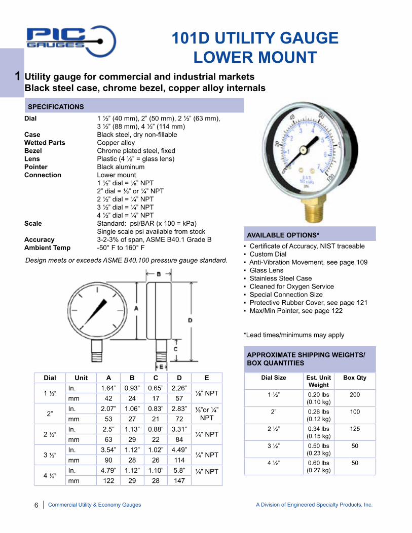
101D UTILITY GAUGELOWER MOUNT
Utility gauge for commercial and industrial marketsBlack steel case, chrome bezel, copper alloy internals
Dial 1 ½” (40 mm), 2” (50 mm), 2 ½” (63 mm), 3 ½” (88 mm), 4 ½” (114 mm) Case Black steel, dry non-fillable Wetted Parts Copper alloyBezel Chrome plated steel, fixedLens Plastic (4 ½” = glass lens)Pointer Black aluminumConnection Lower mount 1 ½” dial = ⅛” NPT 2” dial = ⅛” or ¼” NPT 2 ½” dial = ¼” NPT 3 ½” dial = ¼” NPT 4 ½” dial = ¼” NPTScale Standard: psi/BAR (x 100 = kPa) Single scale psi available from stockAccuracy 3-2-3% of span, ASME B40.1 Grade BAmbient Temp -50° F to 160° F ▪ Certificate of Accuracy, NIST traceable
▪ Custom Dial▪ Anti-Vibration Movement, see page 109▪ Glass Lens▪ Stainless Steel Case▪ Cleaned for Oxygen Service▪ Special Connection Size▪ Protective Rubber Cover, see page 121▪ Max/Min Pointer, see page 122
*Lead times/minimums may apply
Dial Size Est. Unit Weight
Box Qty
1 ½” 0.20 lbs (0.10 kg)
200
2” 0.26 lbs (0.12 kg)
100
2 ½” 0.34 lbs (0.15 kg)
125
3 ½” 0.50 lbs (0.23 kg)
50
4 ½” 0.60 lbs (0.27 kg)
50
Dial Unit A B C D E
1 ½” In. 1.64” 0.93” 0.65” 2.26”
⅛” NPTmm 42 24 17 57
2”In. 2.07” 1.06” 0.83” 2.83” ⅛”or ¼”
NPTmm 53 27 21 72
2 ½” In. 2.5” 1.13” 0.88” 3.31”
¼” NPTmm 63 29 22 84
3 ½” In. 3.54” 1.12” 1.02” 4.49”
¼” NPTmm 90 28 26 114
4 ½” In. 4.79” 1.12” 1.10” 5.8” ¼” NPTmm 122 29 28 147
1
Commercial Utility & Economy Gauges
Design meets or exceeds ASME B40.100 pressure gauge standard.

A Division of Engineered Specialty Products, Inc. 7
SPECIFICATIONS
AVAILABLE OPTIONS*
APPROXIMATE SHIPPING WEIGHTS/BOX QUANTITIES
102D UTILITY GAUGECENTER BACK MOUNT
Utility gauge for commercial and industrial marketsBlack steel case, chrome bezel, copper alloy internals
Dial 1 ½” (40 mm), 2” (50 mm), 2 ½” (63 mm), 3 ½” (88 mm), 4 ½” (114 mm) Case Black steel, dry non-fillable Wetted Parts Copper alloyBezel Chrome plated steel, fixedLens PlasticPointer Black aluminumConnection Center back mount 1 ½” dial = ⅛” NPT 2” dial = ⅛” or ¼” NPT 2 ½” dial = ¼” NPT 3 ½” dial = ¼” NPT 4 ½” dial = ¼” NPTScale Standard: psi/BAR (x 100 = kPa)Accuracy 3-2-3% of span, ASME B40.1 Grade BAmbient Temp -50° F to 160° F
▪ Certificate of Accuracy, NIST traceable ▪ Custom Dial▪ Anti-Vibration Movement, see page 109▪ Glass Lens▪ Stainless Steel Case▪ Cleaned for Oxygen Service▪ Special Connection Size▪ Protective Rubber Cover, see page 121▪ Max/Min Pointer, see page 122
*Lead times/minimums may apply
Dial Size Est. Unit Weight
Box Qty
1 ½” 0.20 lbs (0.10 kg)
200
2” 0.26 lbs (0.13 kg)
100
2 ½” 0.34 lbs (0.17 kg)
125
3 ½” 0.45 lbs(0.22 kg)
50
4 ½” 0.65 lbs(0.30 kg)
25
Dial Unit A B C D E
1 ½” In. 1.64” 0.93” 0.63” 1.54”
⅛” NPTmm 42 24 16 39
2”In. 2.07” 1.03” 0.89” 1.90” ⅛”or ¼”
NPTmm 53 26 23 48
2 ½” In. 2.5” 1.17” 0.90” 1.97”
¼” NPTmm 63 30 23 50
3 ½” In. 3.49” 1.22” 0.83” 2.02”
¼” NPTmm 89 31 21 51
4 ½” In. 4.5” 1.31” 0.94” 2.18” ¼” NPTmm 114 33 24 55
1
Commercial Utility & Economy Gauges
Design meets or exceeds ASME B40.100 pressure gauge standard.

8 A Division of Engineered Specialty Products, Inc.
SPECIFICATIONS
AVAILABLE OPTIONS*
APPROXIMATE SHIPPING WEIGHTS/BOX QUANTITIES
103D UTILITY GAUGEU-CLAMP PANEL MOUNT
Utility gauge for commercial and industrial marketsChrome case and bezel, copper alloy internals
Dial 1 ½” (40 mm), 2” (50 mm), 2 ½” (63 mm), 3 ½” (88 mm) Case Chrome plated steel, dry non-fillable (3 ½” = painted steel with plastic, twist-off lens)Wetted Parts Copper alloyBezel Chrome plated steel, fixedLens PlasticPointer Black aluminumConnection Center back mount with u-clamp 1 ½” dial = ⅛” NPT 2” dial = ⅛” or ¼” NPT 2 ½” dial = ¼” NPT 3 ½” dial = ¼” NPTScale Standard: psi/BAR (x 100 = kPa)Accuracy 3-2-3% of span, ASME B40.1 Grade BAmbient Temp -50° F to 160° F
▪ Certificate of Accuracy, NIST traceable ▪ Custom Dial▪ Anti-Vibration Movement, see page 109▪ Glass Lens▪ Stainless Steel Case▪ Cleaned for Oxygen Service▪ Special Connection Size▪ Protective Rubber Cover, see page 121▪ Max/Min Pointer, see page 122
*Lead times/minimums may apply
Dial Size Est. Unit Weight
Box Qty
1 ½” 0.20 lbs(0.10 kg)
100
2” 0.30 lbs(0.14 kg)
100
2 ½” 0.35 lbs(0.18 kg)
100
3 ½” 0.60 lbs(0.26 kg)
50
Dial Unit A B C D G E
1 ½” In. 1.84” 1.03” 0.63” 1.61” 1.61”
⅛” NPTmm 47 26 16 41 41
2”In. 2.31” 1.18” 0.73” 1.84” 2.04” ⅛”or ¼”
NPTmm 59 30 19 47 52
2 ½” In. 2.68” 1.12” 0.76” 1.87” 2.44”
¼” NPTmm 68 28 19 48 62
3 ½” In. 3.98” 1.23” 0.67” 2.02” 3.59”
¼” NPTmm 101 31 17 51 91
1
Commercial Utility & Economy Gauges
Design meets or exceeds ASME B40.100 pressure gauge standard.
A Division of Engineered Specialty Products, Inc. 9
SPECIFICATIONS
AVAILABLE OPTIONS*
APPROXIMATE SHIPPING WEIGHTS/BOX QUANTITIES
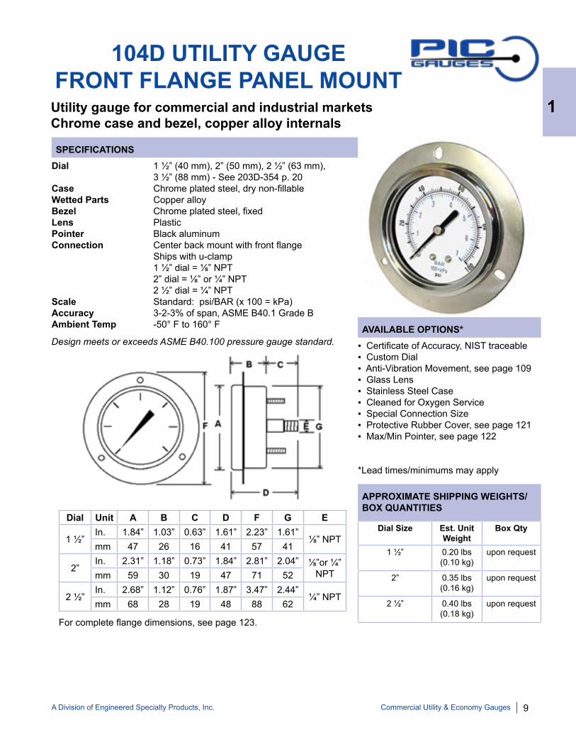
104D UTILITY GAUGEFRONT FLANGE PANEL MOUNT
Utility gauge for commercial and industrial marketsChrome case and bezel, copper alloy internals
Dial 1 ½” (40 mm), 2” (50 mm), 2 ½” (63 mm), 3 ½” (88 mm) - See 203D-354 p. 20Case Chrome plated steel, dry non-fillableWetted Parts Copper alloyBezel Chrome plated steel, fixedLens PlasticPointer Black aluminumConnection Center back mount with front flange Ships with u-clamp 1 ½” dial = ⅛” NPT 2” dial = ⅛” or ¼” NPT 2 ½” dial = ¼” NPTScale Standard: psi/BAR (x 100 = kPa)Accuracy 3-2-3% of span, ASME B40.1 Grade BAmbient Temp -50° F to 160° F
▪ Certificate of Accuracy, NIST traceable▪ Custom Dial▪ Anti-Vibration Movement, see page 109▪ Glass Lens▪ Stainless Steel Case▪ Cleaned for Oxygen Service▪ Special Connection Size▪ Protective Rubber Cover, see page 121▪ Max/Min Pointer, see page 122
*Lead times/minimums may apply
Dial Size Est. Unit Weight
Box Qty
1 ½” 0.20 lbs (0.10 kg)
upon request
2” 0.35 lbs (0.16 kg)
upon request
2 ½” 0.40 lbs (0.18 kg)
upon request
Dial Unit A B C D F G E
1 ½” In. 1.84” 1.03” 0.63” 1.61” 2.23” 1.61”
⅛” NPTmm 47 26 16 41 57 41
2”In. 2.31” 1.18” 0.73” 1.84” 2.81” 2.04” ⅛”or ¼”
NPTmm 59 30 19 47 71 52
2 ½” In. 2.68” 1.12” 0.76” 1.87” 3.47” 2.44”
¼” NPTmm 68 28 19 48 88 62
1
Commercial Utility & Economy Gauges
For complete flange dimensions, see page 123.
Design meets or exceeds ASME B40.100 pressure gauge standard.

10 A Division of Engineered Specialty Products, Inc.
SE-100 SERIES UTILITY GAUGE
Utility gauge for commercial and industrial marketsBlack steel case and bezel, copper alloy internals
SE-102D SERIESSE-101D SERIES
NOTE: Because of continuing improvements, increments/specifications are subject to change without notice. Stock ranges vary by dial size and configuration. Consult PIC Gauges for availability.
Dial Range Figure Intervals
Graduation Intervals
30/0”hg Vac 5” hg 0.5” hg
0/15 psi 2 psi 0.1 psi
0/30 psi 5 psi 0.5 psi
0/60 psi 10 psi 1 psi
0/100 psi 20 psi 2 psi
0/160 psi 20 psi 2 psi
0/200 psi 40 psi 5 psi
0/300 psi 50 psi 5 psi
0/400 psi 50 psi 5 psi
0/600 psi 100 psi 10 psi
STANDARD DIAL CONFIGURATIONS FOR
SE-100 SERIES
1
Commercial Utility & Economy Gauges

A Division of Engineered Specialty Products, Inc. 11
SPECIFICATIONS
AVAILABLE OPTIONS*
APPROXIMATE SHIPPING WEIGHTS/BOX QUANTITIES
SE-101D UTILITY GAUGELOWER MOUNT
Utility gauge for commercial and industrial marketsBlack steel case and bezel, copper alloy internals
Dial 1 ½” (40 mm), 2” (50 mm), 2 ½” (63 mm) Case Black steel, dry non-fillable Wetted Parts Copper alloyBezel Black painted steel, fixedLens GlassPointer Black aluminumConnection Lower mount 1 ½” dial = ⅛” NPT 2” dial = ⅛” or ¼” NPT 2 ½” dial = ¼” NPTScale Standard: psi/BAR (x 100 = kPa)Accuracy 3-2-3% of span, ASME B40.1 Grade BAmbient Temp -50° F to 160° F
▪ Certificate of Accuracy, NIST traceable▪ Custom Dial▪ Anti-Vibration Movement, see page 109▪ Cleaned for Oxygen Service▪ Special Connection Size▪ Protective Rubber Cover, see page 121▪ Plastic Lens▪ Max/Min Pointer, see page 122
*Lead times/minimums may apply
Dial Size Est. Unit Weight
Box Qty
1 ½” 0.10 lbs(0.06 kg)
100
2” 0.20 lbs(0.10 kg)
100
2 ½” 0.30 lbs(0.14 kg)
100
Dial Unit A B C D E
1 ½”In. 1.64” 0.93” 0.63” 2.27”
⅛” NPTmm 42 24 16 58
2”In. 2.07” 1.03” 0.83” 2.90” ⅛”or ¼”
NPTmm 53 26 21 74
2 ½”In. 2.5” 1.17” 0.86” 3.36”
¼” NPTmm 63 30 22 26
1
Commercial Utility & Economy Gauges
Design meets or exceeds ASME B40.100 pressure gauge standard.
12 A Division of Engineered Specialty Products, Inc.
SPECIFICATIONS
AVAILABLE OPTIONS*
APPROXIMATE SHIPPING WEIGHTS/BOX QUANTITIES
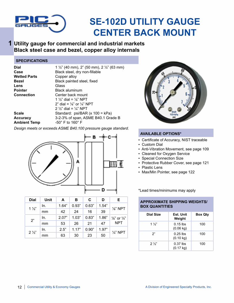
SE-102D UTILITY GAUGECENTER BACK MOUNT
Utility gauge for commercial and industrial marketsBlack steel case and bezel, copper alloy internals
Dial 1 ½” (40 mm), 2” (50 mm), 2 ½” (63 mm)Case Black steel, dry non-fillable Wetted Parts Copper alloyBezel Black painted steel, fixedLens GlassPointer Black aluminumConnection Center back mount 1 ½” dial = ⅛” NPT 2” dial = ⅛” or ¼” NPT 2 ½” dial = ¼” NPTScale Standard: psi/BAR (x 100 = kPa)Accuracy 3-2-3% of span, ASME B40.1 Grade BAmbient Temp -50° F to 160° F
▪ Certificate of Accuracy, NIST traceable▪ Custom Dial▪ Anti-Vibration Movement, see page 109▪ Cleaned for Oxygen Service▪ Special Connection Size▪ Protective Rubber Cover, see page 121▪ Plastic Lens▪ Max/Min Pointer, see page 122
*Lead times/minimums may apply
Dial Size Est. Unit Weight
Box Qty
1 ½” 0.15 lbs(0.06 kg)
100
2” 0.25 lbs(0.10 kg)
100
2 ½” 0.37 lbs(0.17 kg)
100
Dial Unit A B C D E
1 ½” In. 1.64” 0.93” 0.63” 1.54”
⅛” NPTmm 42 24 16 39
2”In. 2.07” 1.03” 0.83” 1.86” ⅛” or ¼”
NPTmm 53 26 21 47
2 ½” In. 2.5” 1.17” 0.90” 1.97”
¼” NPTmm 63 30 23 50
1
Commercial Utility & Economy Gauges
Design meets or exceeds ASME B40.100 pressure gauge standard.
A Division of Engineered Specialty Products, Inc. 13
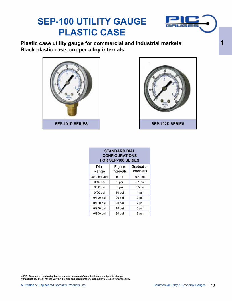
SEP-100 UTILITY GAUGE PLASTIC CASE
Plastic case utility gauge for commercial and industrial marketsBlack plastic case, copper alloy internals
SEP-101D SERIES SEP-102D SERIES
NOTE: Because of continuing improvements, increments/specifications are subject to change without notice. Stock ranges vary by dial size and configuration. Consult PIC Gauges for availability.
Dial Range
Figure Intervals
Graduation Intervals
30/0”hg Vac 5” hg 0.5” hg
0/15 psi 2 psi 0.1 psi
0/30 psi 5 psi 0.5 psi
0/60 psi 10 psi 1 psi
0/100 psi 20 psi 2 psi
0/160 psi 20 psi 2 psi
0/200 psi 40 psi 5 psi
0/300 psi 50 psi 5 psi
STANDARD DIAL CONFIGURATIONS
FOR SEP-100 SERIES
1
Commercial Utility & Economy Gauges

14 A Division of Engineered Specialty Products, Inc.
SPECIFICATIONS
AVAILABLE OPTIONS*
APPROXIMATE SHIPPING WEIGHTS/BOX QUANTITIES
SEP-101D UTILITY GAUGEPLASTIC CASE
Plastic case utility gauge for commercial and industrial marketsBlack plastic case, copper alloy internals
Dial 2” (50 mm)Case Plastic, dry non-fillable Wetted Parts Copper alloyLens PlasticPointer Black aluminumConnection Lower mount 2” dial = ⅛” or ¼” NPTScale Standard: psi/BAR (x 100 = kPa)Accuracy 3-2-3% of span, ASME B40.1 Grade BAmbient Temp -40° F to 140° F
▪ Certificate of Accuracy, NIST traceable▪ Custom Dial▪ Anti-Vibration Movement, see page 109▪ Cleaned for Oxygen Service▪ Special Connection Size▪ Protective Rubber Cover, see page 121▪ Max/Min Pointer, see page 122
*Lead times/minimums may apply
Dial Size Est. Unit Weight
Box Qty
2” 0.15 lbs(0.08 kg)
100
Dial Unit A B C D E
2”In. 2.09” 1.14” 0.83” 2.83” ⅛” or ¼”
NPTmm 53 29 21 72
1
Commercial Utility & Economy Gauges
Design meets or exceeds ASME B40.100 pressure gauge standard.

A Division of Engineered Specialty Products, Inc. 15
SPECIFICATIONS
AVAILABLE OPTIONS*
APPROXIMATE SHIPPING WEIGHTS/BOX QUANTITIES
SEP-102D UTILITY GAUGEPLASTIC CASE
Plastic case utility gauge for commercial and industrial marketsBlack plastic case, copper alloy internals
Dial 2” (50 mm)Case Plastic, dry non-fillable Wetted Parts Copper alloyLens PlasticPointer Black aluminumConnection Center back mount 2” dials = ¼” NPTScale Standard: psi/BAR (x 100 = kPa)Accuracy 3-2-3% of span, ASME B40.1 Grade BAmbient Temp -40° F to 140° F
▪ Certificate of Accuracy, NIST traceable▪ Custom Dial▪ Anti-Vibration Movement, see page 109▪ Cleaned for Oxygen Service▪ Special Connection Size▪ Protective Rubber Cover, see page 121▪ Max/Min Pointer, see page 122
*Lead times/minimums may apply
Dial Size Est. Unit Weight
Box Qty
2” 0.20 lbs(0.08 kg)
100
1
Commercial Utility & Economy Gauges
Design meets or exceeds ASME B40.100 pressure gauge standard.
Dial Unit A B C D E
2”In. 2.11” 1.06” 0.71” 1.77”
¼” NPTmm 54 27 18 45

16 A Division of Engineered Specialty Products, Inc.
NOTE: Because of continuing improvements, increments/specifications are subject to change without notice. Stock ranges vary by dial size and configuration. Consult PIC Gauges for availability.
200 SERIES LIQUID FILLED GAUGE
Glycerine filled for added durability in applications where vibration or pulsation is presentStainless steel case and bezel, copper alloy internals
203L SERIES 204L SERIES
201L SERIES 202L SERIES
Dial Range
Figure Intervals
Graduation Intervals
30/0”hg Vac 5” hg 0.5” hg
30/0/15 psi 10” hg/5 psi 1” hg/0.5 psi
30/0/30 psi 10” hg/5psi 1” hg/0.5 psi
30/0/60 psi 30” hg/10psi 2” hg/1 psi
30/0/100 psi 30” hg/20psi 5” hg/2 psi
30/0/150 psi 30” hg/30psi 5” hg/2 psi
30/0/300 psi 30” hg/50psi 10” hg/5 psi
0/15 psi 2 psi 0.1 psi
0/30 psi 5 psi 0.5 psi
Dial Range
Figure Intervals
Graduation Intervals
0/60 psi 10 psi 0.5 psi
0/100 psi 20 psi 2 psi
0/160 psi 20 psi 2 psi
0/200 psi 40 psi 5 psi
0/300 psi 50 psi 5 psi
0/400 psi 50 psi 5 psi
0/500 psi 100 psi 10 psi
0/600 psi 100 psi 10 psi
0/800 psi 100 psi 10 psi
Dial Range
Figure Intervals
Graduation Intervals
0/1000 psi 200 psi 20 psi
0/1500 psi 200 psi 20 psi
0/2000 psi 400 psi 40 psi
0/3000 psi 500 psi 50 psi
0/4000 psi 500 psi 50 psi
0/5000 psi 1000 psi 100 psi
0/6000 psi 1000 psi 100 psi
0/10,000 psi 2000 psi 200 psi
0/15,000 psi 2000 psi 200 psi
STANDARD DIAL CONFIGURATIONS FOR 200 SERIES
2
Stainless Steel Case, Copper alloy Internals
A Division of Engineered Specialty Products, Inc. 17
SPECIFICATIONS
AVAILABLE OPTIONS*
APPROXIMATE SHIPPING WEIGHTS/BOX QUANTITIES
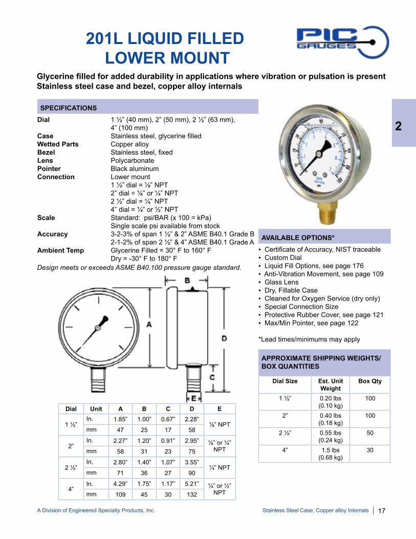
201L LIQUID FILLED LOWER MOUNT
Glycerine filled for added durability in applications where vibration or pulsation is presentStainless steel case and bezel, copper alloy internals
Dial 1 ½” (40 mm), 2” (50 mm), 2 ½” (63 mm), 4” (100 mm)Case Stainless steel, glycerine filled Wetted Parts Copper alloyBezel Stainless steel, fixedLens PolycarbonatePointer Black aluminumConnection Lower mount 1 ½” dial = ⅛” NPT 2” dial = ⅛” or ¼” NPT 2 ½” dial = ¼” NPT 4” dial = ¼” or ½” NPTScale Standard: psi/BAR (x 100 = kPa) Single scale psi available from stockAccuracy 3-2-3% of span 1 ½” & 2” ASME B40.1 Grade B 2-1-2% of span 2 ½” & 4” ASME B40.1 Grade AAmbient Temp Glycerine Filled = 30° F to 160° F Dry = -30° F to 180° F
▪ Certificate of Accuracy, NIST traceable▪ Custom Dial▪ Liquid Fill Options, see page 176▪ Anti-Vibration Movement, see page 109▪ Glass Lens▪ Dry, Fillable Case▪ Cleaned for Oxygen Service (dry only)▪ Special Connection Size▪ Protective Rubber Cover, see page 121▪ Max/Min Pointer, see page 122
*Lead times/minimums may apply
Dial Size Est. Unit Weight
Box Qty
1 ½” 0.20 lbs(0.10 kg)
100
2” 0.40 lbs(0.18 kg)
100
2 ½” 0.55 lbs(0.24 kg)
50
4” 1.5 lbs(0.68 kg)
30
Dial Unit A B C D E
1 ½” In. 1.85” 1.00” 0.67” 2.28”
⅛” NPTmm 47 25 17 58
2”In. 2.27” 1.20” 0.91” 2.95” ⅛” or ¼”
NPTmm 58 31 23 75
2 ½” In. 2.80” 1.40” 1.07” 3.55”
¼” NPTmm 71 36 27 90
4” In. 4.29” 1.75” 1.17” 5.21” ¼” or ½”
NPTmm 109 45 30 132
2
Stainless Steel Case, Copper alloy Internals
Design meets or exceeds ASME B40.100 pressure gauge standard.

18 A Division of Engineered Specialty Products, Inc.
SPECIFICATIONS
AVAILABLE OPTIONS*
APPROXIMATE SHIPPING WEIGHTS/BOX QUANTITIES
202L LIQUID FILLEDCENTER BACK MOUNT
Dial 1 ½” (40 mm), 2” (50 mm), 2 ½” (63 mm), 4” (100 mm)Case Stainless steel, glycerine filled Wetted Parts Copper alloyBezel Stainless steel, fixedLens PolycarbonatePointer Black aluminumConnection Center back mount 1 ½” dial = ⅛” NPT 2” dial = ⅛” or ¼” NPT 2 ½” dial = ¼” NPT 4” dial = ¼” NPTScale Standard: psi/BAR (x 100 = kPa) Single scale psi available from stock - 2 ½” OnlyAccuracy 3-2-3% of span 1 ½” & 2” ASME B40.1 Grade B 2-1-2% of span 2 ½” & 4” ASME B40.1 Grade AAmbient Temp Glycerine Filled = 30° F to 160° F Dry = -30° F to 180° F
▪ Certificate of Accuracy, NIST traceable▪ Custom Dial▪ Liquid Fill Options, see page 176▪ Anti-Vibration Movement, see page 109▪ Glass Lens▪ Dry, Fillable Case▪ Cleaned for Oxygen Service (dry only)▪ Special Connection Size▪ Protective Rubber Cover, see page 121▪ Max/Min Pointer, see page 122
*Lead times/minimums may apply
Dial Size Est. Unit Weight
Box Qty
1 ½” 0.20 lbs(0.10 kg)
100
2” 0.40 lbs(0.18 kg)
100
2 ½” 0.55 lbs(0.26 kg)
50
4” 1.50 lbs(0.70 kg)
30
2
Stainless Steel Case, Copper alloy Internals
Glycerine filled for added durability in applications where vibration or pulsation is presentStainless steel case and bezel, copper alloy internals
Design meets or exceeds ASME B40.100 pressure gauge standard.
Dial Unit A B C D E G
1 ½” In. 1.85” 1.02” 0.72” 1.74”
⅛” NPT1.63”
mm 47 26 18 44 42
2”In. 2.28” 1.18” 0.94” 2.08” ⅛” or
¼” NPT2.05”
mm 58 30 24 53 52
2 ½”In. 2.80” 1.34” 0.94” 2.28”
¼” NPT2.48”
mm 71 34 24 58 63
4”In. 4.29” 1.78” 1.37” 3.15”
¼” NPT3.91”
mm 109 45 35 80 99

A Division of Engineered Specialty Products, Inc. 19
SPECIFICATIONS
AVAILABLE OPTIONS*
APPROXIMATE SHIPPING WEIGHTS/BOX QUANTITIES
203L LIQUID FILLED U-CLAMP PANEL MOUNT
Dial 1 ½” (40 mm), 2” (51 mm), 2 ½” (63 mm), 4” (100 mm)Case Stainless steel, glycerine filled Wetted Parts Copper alloyBezel Stainless steel, fixedLens PolycarbonatePointer Black aluminumConnection Center back mount with u-clamp 1 ½” dial = ⅛” NPT 2” dial = ⅛” or ¼” NPT 2 ½” dial = ¼” NPT 4” dial = ¼” NPTScale Standard: psi/BAR (x 100 = kPa) Single scale psi available from stock - 2 ½” OnlyAccuracy 3-2-3% of span 1 ½” & 2” ASME B40.1 Grade B 2-1-2% of span 2 ½” & 4” ASME B40.1 Grade AAmbient Temp Glycerine Filled = 30° F to 160° F Dry = -30° F to 180° F
▪ Certificate of Accuracy, NIST traceable▪ Custom Dial▪ Liquid Fill Options, see page 176▪ Anti-Vibration Movement, see page 109▪ Glass Lens▪ Dry, Fillable Case▪ Cleaned for Oxygen Service (dry only)▪ Special Connection Size▪ Max/Min Pointer, see page 122
*Lead times/minimums may apply
Dial Size Est. Unit Weight
Box Qty
1 ½” 0.30 lbs (0.13 kg)
100
2” 0.50 lbs (0.23 kg)
100
2 ½” 0.65 lbs (0.29 kg)
50
4” 1.70 lbs (0.76 kg)
30
Dial Unit A B C D E F G
1 ½” In. 1.85” 1.02” 0.72” 1.74”
⅛” NPT2.75” 1.63”
mm 47 26 18 44 70 42
2”In. 2.28” 1.18” 0.94” 2.08” ⅛” or
¼”NPT3.13” 2.05”
mm 58 30 24 53 80 52
2 ½” In. 2.80” 1.34” 0.94” 2.28”
¼” NPT3.84” 2.48”
mm 71 34 24 58 98 63
4” In. 4.29” 1.78” 1.37” 3.15” ¼” or
½”NPT5.6” 3.91”
mm 109 45 35 80 141 99
2
Stainless Steel Case, Copper alloy Internals
Glycerine filled for added durability in applications where vibration or pulsation is presentStainless steel case and bezel, copper alloy internals
Design meets or exceeds ASME B40.100 pressure gauge standard.

20 A Division of Engineered Specialty Products, Inc.
SPECIFICATIONS
AVAILABLE OPTIONS*
APPROXIMATE SHIPPING WEIGHTS/BOX QUANTITIES
3 ½” 203D FILLABLEU-CLAMP PANEL MOUNT
Dial 3 ½” (88 mm)Case Stainless steel, dry yet fillable Wetted Parts Copper alloyBezel Stainless steel, fixedLens PolycarbonatePointer Black aluminumConnection Lower back mount with u-clamp 3 ½” dial = ¼” NPTScale Standard: psi/BAR (x 100 = kPa)Accuracy 2-1-2% of span, ASME B40.1 Grade AAmbient Temp Dry = -30° F to 180° F Glycerine Filled = 30° F to 160° F
▪ Certificate of Accuracy, NIST traceable ▪ Custom Dial▪ Liquid Fill Options, see page 176▪ Anti-Vibration Movement, see page 109▪ Glass Lens▪ Cleaned for Oxygen Service (dry only)▪ Special Connection Size▪ Max/Min Pointer, see page 122
*Lead times/minimums may apply
Dial Size Est. Unit Weight
Box Qty
3 ½” 0.60 lbs(0.28 kg)
50
Dial Unit A B C D E G
3 ½” In. 3.83” 1.13” 1.00” 2.15”
¼” NPT3.50”
mm 97 29 25 55 89
2
Stainless Steel Case, Copper alloy Internals
Dry yet fillable gauge for durability in applications where vibration or pulsation is presentStainless steel case and bezel, copper alloy internals
Design meets or exceeds ASME B40.100 pressure gauge standard.

A Division of Engineered Specialty Products, Inc. 21
SPECIFICATIONS
AVAILABLE OPTIONS*
APPROXIMATE SHIPPING WEIGHTS/BOX QUANTITIES
204L LIQUID FILLEDFRONT FLANGE PANEL MOUNT
Dial 1 ½” (40 mm), 2” (50 mm), 2 ½” (63 mm), 3 ½” (88 mm), 4” (100 mm)Case Stainless steel, glycerine filled Wetted Parts Copper alloyBezel Stainless steel, fixedLens PolycarbonatePointer Black aluminumConnection Center back mount with front flange 1 ½” dial = ⅛” NPT 2” dial = ⅛” or ¼” NPT 2 ½” dial = ¼” NPT 3 ½” dial = ¼” NPT - ships with u-clamp 4” dial = ¼” NPTScale Standard: psi/BAR (x 100 = kPa) Single scale psi available from stock - 2 ½” OnlyAccuracy 3-2-3% of span 1 ½” & 2” ASME B40.1 Grade B 2-1-2% of span 2 ½” & 4” ASME B40.1 Grade AAmbient Temp Glycerine Filled = 30° F to 160° F Dry = -30° F to 180° F
▪ Certificate of Accuracy, NIST traceable ▪ Custom Dial▪ Liquid Fill Options, see page 176▪ Anti-Vibration Movement, see page 109▪ Glass Lens▪ Dry, Fillable Case▪ Cleaned for Oxygen Service (dry only)▪ Special Connection Size▪ Max/Min Pointer, see page 122
*Lead times/minimums may apply
Dial Size Est. Unit Weight
Box Qty
1 ½” 0.30 lbs (0.13 kg)
100
2” 0.50 lbs (0.23 kg)
100
2 ½” 0.60 lbs (0.29 kg)
50
4” 1.70 lbs (0.76 kg)
30
Dial Unit A B C D E F G
1 ½” In. 1.85” 1.02” 0.72” 1.74”
⅛” NPT2.46” 1.63”
mm 47 26 18 44 63 42
2”In. 2.28” 1.18” 0.94” 2.08” ⅛” or
¼”NPT2.81” 2.05”
mm 58 30 24 53 72 52
2 ½” In. 2.80” 1.34” 0.94” 2.28”
¼” NPT3.45” 2.48”
mm 71 34 24 58 88 63
4” In. 4.29” 1.78” 1.37” 3.15” ¼” or
½”NPT5.14” 3.91”
mm 109 45 35 80 130 99
2
Stainless Steel Case, Copper alloy Internals
Glycerine filled for added durability in applications where vibration or pulsation is presentStainless steel case and bezel, copper alloy internals
For complete flange dimensions, see page 123.
Design meets or exceeds ASME B40.100 pressure gauge standard.

22 A Division of Engineered Specialty Products, Inc.
NOTE: Because of continuing improvements, increments/specifications are subject to change without notice. Stock ranges vary by dial size and configuration. Consult PIC Gauges for availability.
210 SERIES FILLABLE GAUGE
212D SERIES211D SERIES
213D SERIES 214D SERIES
Dial Range
Figure Intervals
Graduation Intervals
30/0”hg Vac 5” hg 0.5” hg
30/0/30 psi 10” hg/5 psi 1” hg/0.5 psi
30/0/60 psi 30” hg/10psi 2” hg/1 psi
30/0/100 psi 30” hg/20psi 5” hg/2 psi
30/0/150 psi 30” hg/30psi 5” hg/2 psi
0/15 psi 2 psi 0.1 psi
0/30 psi 5 psi 0.25 psi
Dial Range
Figure Intervals
Graduation Intervals
0/60 psi 10 psi 0.5 psi
0/100 psi 20 psi 2 psi
0/160 psi 20 psi 2 psi
0/200 psi 40 psi 5 psi
0/300 psi 50 psi 5 psi
0/400 psi 50 psi 5 psi
0/600 psi 100 psi 10 psi
Dial Range
Figure Intervals
Graduation Intervals
0/1000 psi 200 psi 20 psi
0/1500 psi 200 psi 20 psi
0/2000 psi 200 psi 20 psi
0/3000 psi 500 psi 50 psi
0/4000 psi 500 psi 100 psi
0/5000 psi 1000 psi 100 psi
0/6000 psi 1000 psi 100 psi
0/10,000 psi 2000 psi 200 psi
STANDARD DIAL CONFIGURATIONS FOR 210 SERIES
2
Stainless Steel Case, Copper alloy Internals
Dry yet fillable gauge with removable bezel, adjustable pointer Stainless steel case and bezel, copper alloy internals

A Division of Engineered Specialty Products, Inc. 23
SPECIFICATIONS
AVAILABLE OPTIONS*
APPROXIMATE SHIPPING WEIGHTS/BOX QUANTITIES
211D REMOVABLE BEZEL LOWER MOUNT
Dial 2 ½” (63 mm)Case Stainless steel, dry - fillable Wetted Parts Copper alloyBezel Removable, stainless steelLens Glass Pointer Adjustable, black aluminumConnection Lower mount 2 ½” dial = ¼” NPTScale Standard: psi/BAR (x 100 = kPa)Accuracy 2-1-2% of span ASME B40.1 Grade AAmbient Temp Dry = -30° F to 180° F Glycerine Filled = 30° F to 160° F
▪ Certificate of Accuracy, NIST traceable▪ Custom Dial▪ Liquid Fill Options, see page 176▪ Anti-Vibration Movement, see page 109▪ Cleaned for Oxygen Service (dry only)▪ Special Connection Size▪ Protective Rubber Cover, see page 121▪ Plastic Lens▪ Max/Min Pointer, see page 122
*Lead times/minimums may apply
Dial Size Est. Unit Weight
Box Qty
2 ½” 0.40 lbs(0.20 kg)
100
Dial Unit A B C D E
2 ½” In. 2.83” 1.42” 1.06” 3.54” ¼”
NPTmm 72 36 27 90
2
Stainless Steel Case, Copper alloy Internals
Dry yet fillable gauge with removable bezel, adjustable pointerStainless steel case and bezel, copper alloy internals
Design meets or exceeds ASME B40.100 pressure gauge standard.

24 A Division of Engineered Specialty Products, Inc.
SPECIFICATIONS
AVAILABLE OPTIONS*
APPROXIMATE SHIPPING WEIGHTS/BOX QUANTITIES
212D REMOVABLE BEZELCENTER BACK MOUNT
Dial 2 ½” (63 mm),Case Stainless steel, dry yet fillable Wetted Parts Copper alloyBezel Removable, stainless steel Lens GlassPointer Adjustable, black aluminumConnection Center back mount 2 ½” dial = ¼” NPTScale Standard: psi/BAR (x 100 = kPa)Accuracy 2-1-2% of span ASME B40.1 Grade AAmbient Temp Dry = -30° F to 180° F Glycerine Filled = 30° F to 160° F
▪ Certificate of Accuracy, NIST traceable▪ Custom Dial▪ Liquid Fill Options, see page 176▪ Anti-Vibration Movement, see page 109▪ Cleaned for Oxygen Service (dry only)▪ Special Connection Size▪ Protective Rubber Cover, see page 121▪ Plastic Lens ▪ Max/Min Pointer, see page 122
*Lead times/minimums may apply
Dial Size Est. Unit Weight
Box Qty
2 ½” 0.40 lbs(0.20 kg)
50
Dial Unit A B C D E F
2 ½” In. 2.83” 1.37” 1.00” 2.49” ¼”
NPT2.29”
mm 72 35 25 63 58
2
Stainless Steel Case, Copper alloy Internals
Dry yet fillable gauge with removable bezel, adjustable pointer Stainless steel case and bezel, copper alloy internals
Design meets or exceeds ASME B40.100 pressure gauge standard.
A Division of Engineered Specialty Products, Inc. 25
SPECIFICATIONS
AVAILABLE OPTIONS*
APPROXIMATE SHIPPING WEIGHTS/BOX QUANTITIES
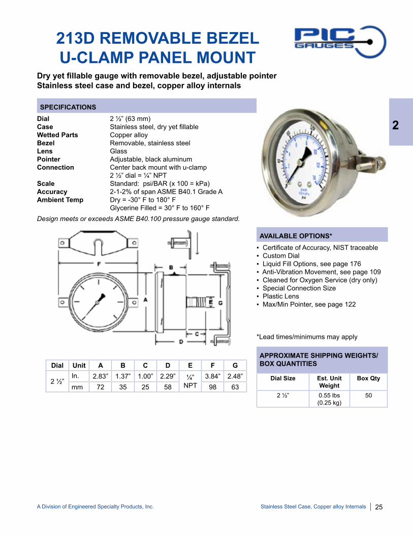
213D REMOVABLE BEZELU-CLAMP PANEL MOUNT
Dial 2 ½” (63 mm)Case Stainless steel, dry yet fillable Wetted Parts Copper alloyBezel Removable, stainless steelLens GlassPointer Adjustable, black aluminumConnection Center back mount with u-clamp 2 ½” dial = ¼” NPTScale Standard: psi/BAR (x 100 = kPa)Accuracy 2-1-2% of span ASME B40.1 Grade AAmbient Temp Dry = -30° F to 180° F Glycerine Filled = 30° F to 160° F
▪ Certificate of Accuracy, NIST traceable▪ Custom Dial▪ Liquid Fill Options, see page 176▪ Anti-Vibration Movement, see page 109▪ Cleaned for Oxygen Service (dry only)▪ Special Connection Size▪ Plastic Lens▪ Max/Min Pointer, see page 122
*Lead times/minimums may apply
Dial Unit A B C D E F G
2 ½” In. 2.83” 1.37” 1.00” 2.29” ¼”
NPT3.84” 2.48”
mm 72 35 25 58 98 63Dial Size Est. Unit
WeightBox Qty
2 ½” 0.55 lbs (0.25 kg)
50
2
Stainless Steel Case, Copper alloy Internals
Dry yet fillable gauge with removable bezel, adjustable pointerStainless steel case and bezel, copper alloy internals
Design meets or exceeds ASME B40.100 pressure gauge standard.
26 A Division of Engineered Specialty Products, Inc.
SPECIFICATIONS
AVAILABLE OPTIONS*
APPROXIMATE SHIPPING WEIGHTS/BOX QUANTITIES
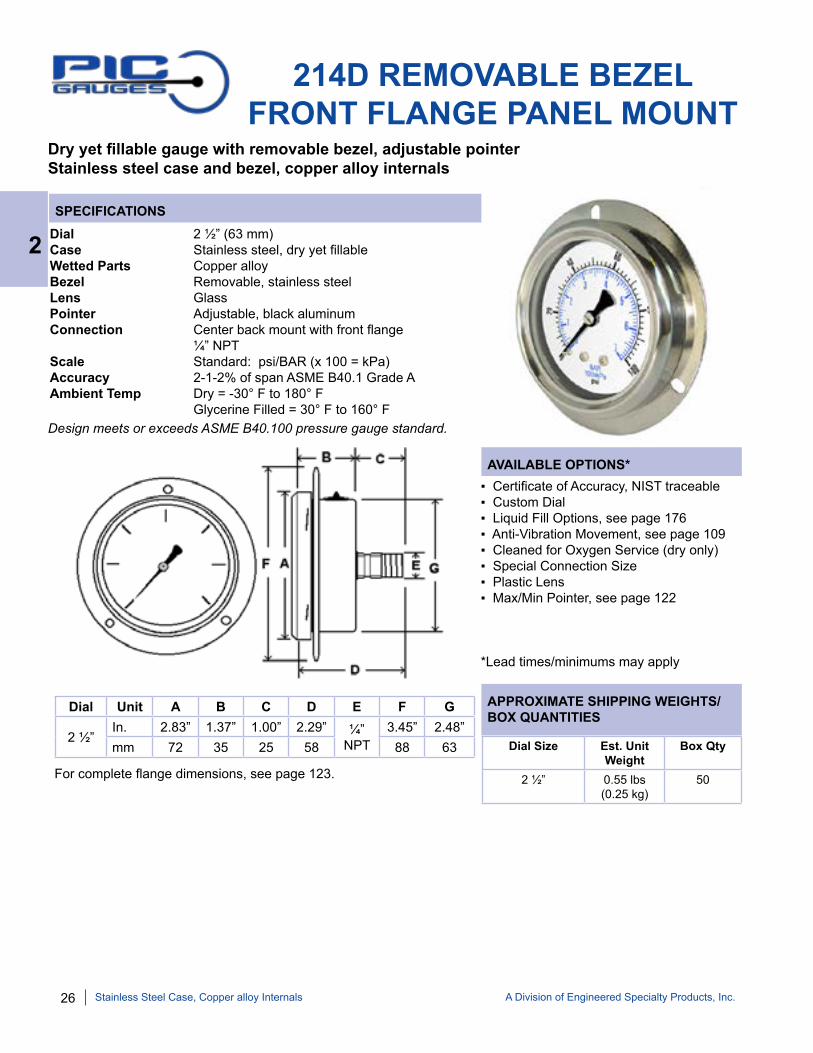
214D REMOVABLE BEZELFRONT FLANGE PANEL MOUNT
Dial 2 ½” (63 mm)Case Stainless steel, dry yet fillable Wetted Parts Copper alloyBezel Removable, stainless steelLens GlassPointer Adjustable, black aluminumConnection Center back mount with front flange ¼” NPT Scale Standard: psi/BAR (x 100 = kPa)Accuracy 2-1-2% of span ASME B40.1 Grade AAmbient Temp Dry = -30° F to 180° F Glycerine Filled = 30° F to 160° F
▪ Certificate of Accuracy, NIST traceable▪ Custom Dial▪ Liquid Fill Options, see page 176▪ Anti-Vibration Movement, see page 109▪ Cleaned for Oxygen Service (dry only)▪ Special Connection Size▪ Plastic Lens▪ Max/Min Pointer, see page 122
*Lead times/minimums may apply
Dial Unit A B C D E F G
2 ½” In. 2.83” 1.37” 1.00” 2.29” ¼”
NPT3.45” 2.48”
mm 72 35 25 58 88 63 Dial Size Est. Unit Weight
Box Qty
2 ½” 0.55 lbs(0.25 kg)
50
2
Stainless Steel Case, Copper alloy Internals
For complete flange dimensions, see page 123.
Dry yet fillable gauge with removable bezel, adjustable pointer Stainless steel case and bezel, copper alloy internals
Design meets or exceeds ASME B40.100 pressure gauge standard.

A Division of Engineered Specialty Products, Inc. 27
SEC-200 SERIES LIQUID FILLED GAUGE
SEC-202L SERIESSEC-201L SERIES
SEC-203L SERIES SEC-204L SERIES
Dial Range
Figure Intervals
Graduation Intervals
30/0”hg Vac 5” hg 0.5” hg
30/0/30 psi 10” hg/10psi 1” hg/1 psi
30/0/60 psi 10” hg/10psi 2” hg/1 psi
30/0/100 psi 30” hg/20psi 5” hg/2 psi
30/0/150 psi 30” hg/20psi 5” hg/2 psi
30/0/300 psi 30” hg/50psi 10” hg/5 psi
0/15 psi 2 psi 0.1 psi
0/30 psi 5 psi 0.5 psi
Dial Range
Figure Intervals
Graduation Intervals
0/60 psi 10 psi 1 psi
0/100 psi 20 psi 2 psi
0/160 psi 20 psi 2 psi
0/200 psi 40 psi 4 psi
0/300 psi 50 psi 5 psi
0/400 psi 50 psi 5 psi
0/500 psi 100 psi 10 psi
0/600 psi 100 psi 10 psi
Dial Range
Figure Intervals
Graduation Intervals
0/1000 psi 200 psi 20 psi
0/1500 psi 200 psi 20 psi
0/2000 psi 400 psi 40 psi
0/3000 psi 500 psi 50 psi
0/4000 psi 500 psi 50 psi
0/5000 psi 1000 psi 100 psi
0/6000 psi 1000 psi 100 psi
0/10,000 psi 2000 psi 200 psi
NOTE: Because of continuing improvements, increments/specifications are subject to change without notice. Stock ranges vary by dial size and configuration. Consult PIC Gauges for availability.
STANDARD DIAL CONFIGURATIONS FOR SEC-200 SERIES
2
Stainless Steel Case, Copper alloy Internals
Glycerine filled for added durability in applications where vibration or pulsation is presentStainless steel case and bezel, copper alloy internals

28 A Division of Engineered Specialty Products, Inc.
SPECIFICATIONS
AVAILABLE OPTIONS*
APPROXIMATE SHIPPING WEIGHTS/BOX QUANTITIES
SEC-201L LIQUID FILLED LOWER MOUNT
Dial 2 ½” (63 mm)Case Stainless steel, glycerine filled Wetted Parts Copper alloyBezel Stainless steel, fixedLens PolycarbonatePointer Black aluminumConnection Lower mount 2 ½” dial = ¼” NPTScale Standard: psi/BAR (x 100 = kPa)Accuracy 3-2-3% of span ASME B40.1 Grade BAmbient Temp Glycerine Filled = 30° F to 160° F Dry = -30° F to 180° F
▪ Certificate of Accuracy, NIST traceable▪ Custom Dial▪ Liquid Fill Options, see page 176▪ Anti-Vibration Movement, see page 109▪ Dry, Fillable Case▪ Special Connection Size▪ Protective Rubber Cover, see page 121▪ Max/Min Pointer, see page 122
*Lead times/minimums may apply
Dial Size Est. Unit Weight
Box Qty
2 ½” 0.45 lbs(0.20 kg)
100
Dial Unit A B C D E
2 ½” In. 2.65” 1.20” 0.88” 3.30” ¼”
NPTmm 68 30 22 84
2
Stainless Steel Case, Copper alloy Internals
Glycerine filled for added durability in applications where vibration or pulsation is presentStainless steel case and bezel, copper alloy internals
Design meets or exceeds ASME B40.100 pressure gauge standard.

A Division of Engineered Specialty Products, Inc. 29
SPECIFICATIONS
AVAILABLE OPTIONS*
APPROXIMATE SHIPPING WEIGHTS/BOX QUANTITIES
SEC-202L LIQUID FILLEDCENTER BACK MOUNT
Dial 2 ½” (63 mm), Case Stainless steel, glycerine filled Wetted Parts Copper alloyBezel Stainless steel, fixedLens PolycarbonatePointer Black aluminumConnection Center back mount 2 ½” dial = ¼” NPTScale Standard: psi/BAR (x 100 = kPa)Accuracy 3-2-3% of span ASME B40.1 Grade BAmbient Temp Glycerine Filled = 30° F to 160° F Dry = -30° F to 180° F
▪ Certificate of Accuracy, NIST traceable ▪ Custom Dial▪ Liquid Fill Options, see page 176▪ Anti-Vibration Movement, see page 109▪ Dry, Fillable Case▪ Special Connection Size▪ Protective Rubber Cover, see page 121▪ Max/Min Pointer, see page 122
*Lead times/minimums may apply
Dial Size Est. Unit Weight
Box Qty
2 ½” 0.45 lbs(0.22 kg)
60
Dial Unit A B C D E
2 ½” In. 2.65” 1.21” 0.91” 2.44” ¼”
NPTmm 68 31 23 62
2
Stainless Steel Case, Copper alloy Internals
Glycerine filled for added durability in applications where vibration or pulsation is presentStainless steel case and bezel, copper alloy internals
Design meets or exceeds ASME B40.100 pressure gauge standard.

30 A Division of Engineered Specialty Products, Inc.
SPECIFICATIONS
AVAILABLE OPTIONS*
APPROXIMATE SHIPPING WEIGHTS/BOX QUANTITIES
SEC-203L LIQUID FILLED U-CLAMP PANEL MOUNT
Dial 2 ½” (63 mm), Case Stainless steel, glycerine filled Wetted Parts Copper alloyBezel Stainless steel, fixedLens PolycarbonatePointer Black aluminumConnection Center back mount with u-clamp 2 ½” dial = ¼” NPTScale Standard: psi/BAR (x 100 = kPa)Accuracy 3-2-3% of span ASME B40.1 Grade BAmbient Temp Glycerine Filled = 30° F to 160° F Dry = -30° F to 180° F
▪ Certificate of Accuracy, NIST traceable▪ Custom Dial▪ Liquid Fill Options, see page 176▪ Anti-Vibration Movement, see page 109▪ Dry, Fillable Case▪ Special Connection Size▪ Max/Min Pointer, see page 122
*Lead times/minimums may apply
Dial Size Est. Unit Weight
Box Qty
2 ½” 0.55 lbs (0.26 kg)
60
Dial Unit A B C D E F G
2 ½” In. 2.65” 1.21” 0.91” 2.12” ¼”
NPT3.84” 2.44”
mm 68 31 23 54 98 61
2
Stainless Steel Case, Copper alloy Internals
Glycerine filled for added durability in applications where vibration or pulsation is presentStainless steel case and bezel, copper alloy internals
Design meets or exceeds ASME B40.100 pressure gauge standard.

A Division of Engineered Specialty Products, Inc. 31
SPECIFICATIONS
AVAILABLE OPTIONS*
APPROXIMATE SHIPPING WEIGHTS/BOX QUANTITIES
SEC-204L LIQUID FILLED FRONT FLANGE PANEL MOUNT
Dial 2 ½” (63 mm)Case Stainless steel, glycerine filled Wetted Parts Copper alloyBezel Stainless steel, fixed Lens PolycarbonatePointer Black aluminumConnection Center back mount with front flange 2 ½” dial = ¼” NPTScale Standard: psi/BAR (x 100 = kPa)Accuracy 3-2-3% of span ASME B40.1 Grade BAmbient Temp Glycerine Filled = 30° F to 160° F Dry = -30° F to 180° F
▪ Certificate of Accuracy, NIST traceable▪ Custom Dial▪ Liquid Fill Options, see page 176▪ Anti-Vibration Movement, see page 109▪ Dry, Fillable Case▪ Special Connection Size▪ Max/Min Pointer, see page 122
*Lead times/minimums may apply
Dial Size Est. Unit Weight
Box Qty
2 ½” 0.55 lbs (0.26 kg)
60
Dial Unit A B C D E F G
2 ½” In. 2.65” 1.21” 0.91” 2.12” ¼”
NPT3.46” 2.44”
mm 68 31 23 54 88 61
2
Stainless Steel Case, Copper alloy Internals
For complete flange dimensions, see page 123.
Glycerine filled for added durability in applications where vibration or pulsation is presentStainless steel case and bezel, copper alloy internals
Design meets or exceeds ASME B40.100 pressure gauge standard.
32 A Division of Engineered Specialty Products, Inc.
NOTE: Because of continuing improvements, increments/specifications are subject to change without notice. Stock ranges vary by dial size and configuration. Consult PIC Gauges for availability.
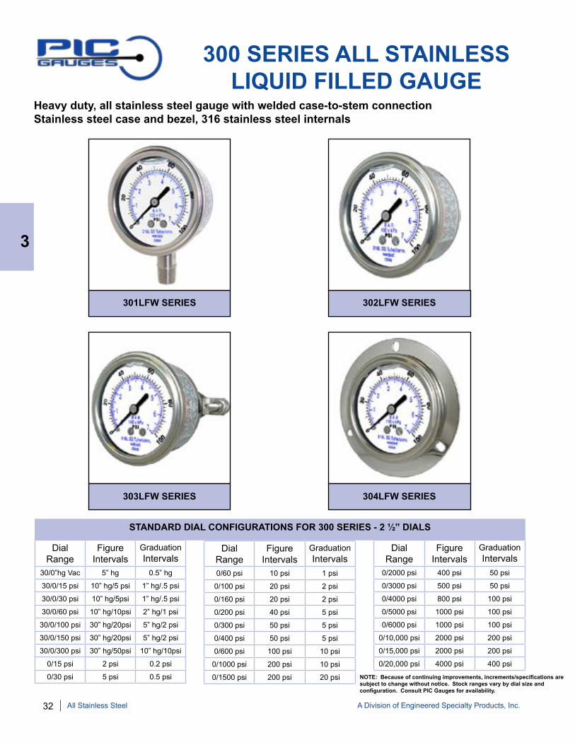
300 SERIES ALL STAINLESSLIQUID FILLED GAUGE
Heavy duty, all stainless steel gauge with welded case-to-stem connectionStainless steel case and bezel, 316 stainless steel internals
302LFW SERIES301LFW SERIES
303LFW SERIES 304LFW SERIES
Dial Range
Figure Intervals
Graduation Intervals
30/0”hg Vac 5” hg 0.5” hg
30/0/15 psi 10” hg/5 psi 1” hg/.5 psi
30/0/30 psi 10” hg/5psi 1” hg/.5 psi
30/0/60 psi 10” hg/10psi 2” hg/1 psi
30/0/100 psi 30” hg/20psi 5” hg/2 psi
30/0/150 psi 30” hg/20psi 5” hg/2 psi
30/0/300 psi 30” hg/50psi 10” hg/10psi
0/15 psi 2 psi 0.2 psi
0/30 psi 5 psi 0.5 psi
Dial Range
Figure Intervals
Graduation Intervals
0/60 psi 10 psi 1 psi
0/100 psi 20 psi 2 psi
0/160 psi 20 psi 2 psi
0/200 psi 40 psi 5 psi
0/300 psi 50 psi 5 psi
0/400 psi 50 psi 5 psi
0/600 psi 100 psi 10 psi
0/1000 psi 200 psi 10 psi
0/1500 psi 200 psi 20 psi
Dial Range
Figure Intervals
Graduation Intervals
0/2000 psi 400 psi 50 psi
0/3000 psi 500 psi 50 psi
0/4000 psi 800 psi 100 psi
0/5000 psi 1000 psi 100 psi
0/6000 psi 1000 psi 100 psi
0/10,000 psi 2000 psi 200 psi
0/15,000 psi 2000 psi 200 psi
0/20,000 psi 4000 psi 400 psi
STANDARD DIAL CONFIGURATIONS FOR 300 SERIES - 2 ½” DIALS
3
All Stainless Steel

A Division of Engineered Specialty Products, Inc. 33
AVAILABLE OPTIONS*
APPROXIMATE SHIPPING WEIGHTS/BOX QUANTITIES
SPECIFICATIONS
301LFW ALL STAINLESSLOWER MOUNT
Dial 1 ½” (40 mm), 2” (50 mm), 2 ½” (63 mm), 4” (100 mm) See page 37, 6” (150 mm) - See 6001 page 53Case Stainless steel, glycerine filled (available dry) Welded case-to-stem connectionWetted Parts 316 stainless steelBezel Stainless steel, fixedLens PolycarbonatePointer Black aluminumConnection Lower mount 1 ½” dial = ⅛” NPT 2” dial = ⅛” or ¼” NPT 2 ½” dial = ¼” NPTScale Standard: psi/BAR (x 100 = kPa)Accuracy 3-2-3% of span 1 ½” & 2” ASME B40.1 Grade B 2-1-2% of span 2 ½” ASME B40.1 Grade AAmbient Temp Glycerine Filled = 30° F to 160° F Dry = -30° F to 180° F
Dial Unit A B C D E
1 ½” In. 1.84” 1.03” 0.73” 2.32” ⅛”
NPTmm 47 26 19 59
2”In. 2.25” 1.15” 0.91” 2.93” ⅛”or
¼” NPTmm 57 30 23 75
2 ½” In. 2.70” 1.39” 1” 3.61” ¼”
NPTmm 69 35 25 92
Dial Size Est. Unit Weight
Box Qty
1 ½” 0.20 lbs(0.10 kg)
100
2” 0.40 lbs(0.18 kg)
100
2 ½” 0.55 lbs(0.24 kg)
90
3
All Stainless Steel
▪ Certificate of Accuracy, NIST traceable▪ Custom Dial▪ Liquid Fill Options, see page 176▪ Anti-Vibration Movement, see page 109▪ Dry, Fillable Case▪ Glass Lens▪ Cleaned for Oxygen Service (dry only)▪ Special Connection Size▪ Protective Rubber Cover, see page 121▪ Single Scale ▪ Max/Min Pointer, see page 122
*Lead times/minimums may apply
Heavy duty, all stainless steel gauge with welded case-to-stem connectionStainless steel case and bezel, 316 stainless steel internalsGlycerine filled for added durability in applications where vibration or pulsation is present
Design meets or exceeds ASME B40.100 pressure gauge standard.

34 A Division of Engineered Specialty Products, Inc.
AVAILABLE OPTIONS*
APPROXIMATE SHIPPING WEIGHTS/BOX QUANTITIES
SPECIFICATIONS
302LFW ALL STAINLESS CENTER BACK MOUNT
Dial 1 ½” (40 mm), 2” (50 mm), 2 ½” (63 mm), 4” (100 mm) - See 312D page 40 6” (150 mm) - See 6002 page 54Case Stainless steel, glycerine filled (available dry) Welded case-to-stem connectionWetted Parts 316 stainless steelBezel Stainless steel, fixedLens PolycarbonatePointer Black aluminumConnection Center back mount 1 ½” dial = ⅛” NPT 2” dial = ⅛” or ¼” NPT 2 ½” dial = ¼” NPTScale Standard: psi/BAR (x 100 = kPa)Accuracy 3-2-3% of span 1 ½” & 2” ASME B40.1 Grade B 2-1-2% of span 2 ½” ASME B40.1 Grade A 1% of span 4” ASME B40.1 Grade 1AAmbient Temp Glycerine Filled = 30° F to 160° F Dry = -30° F to 180° F
Dial Size Est. Unit Weight
Box Qty
1 ½” 0.20 lbs(0.10 kg)
100
2” 0.40 lbs(0.18 kg)
100
2 ½” 0.60 lbs(0.28 kg)
50
Dial Unit A B C D E
1 ½”In. 1.83” 1.01” 0.89” 1.90” ⅛”
NPTmm 46 26 23 48
2”In. 2.25” 1.17” 1.00” 2.17” ⅛” or
¼”mm 57 30 25 55
2 ½” In. 2.71” 1.40” 1.31” 2.71” ¼”
NPTmm 69 36 33 69
3
All Stainless Steel
▪ Certificate of Accuracy, NIST traceable ▪ Custom Dial▪ Liquid Fill Options, see page 176▪ Anti-Vibration Movement, see page 109▪ Dry, Fillable Case▪ Glass Lens▪ Cleaned for Oxygen Service (dry only)▪ Special Connection Size▪ Protective Rubber Cover, see page 121▪ Single Scale▪ Max/Min Pointer, see page 122
*Lead times/minimums may apply
Heavy duty, all stainless steel gauge with welded case-to-stem connectionStainless steel case and bezel, 316 stainless steel internalsGlycerine filled for added durability in applications where vibration or pulsation is present
Design meets or exceeds ASME B40.100 pressure gauge standard.
A Division of Engineered Specialty Products, Inc. 35
AVAILABLE OPTIONS*
APPROXIMATE SHIPPING WEIGHTS/BOX QUANTITIES
SPECIFICATIONS
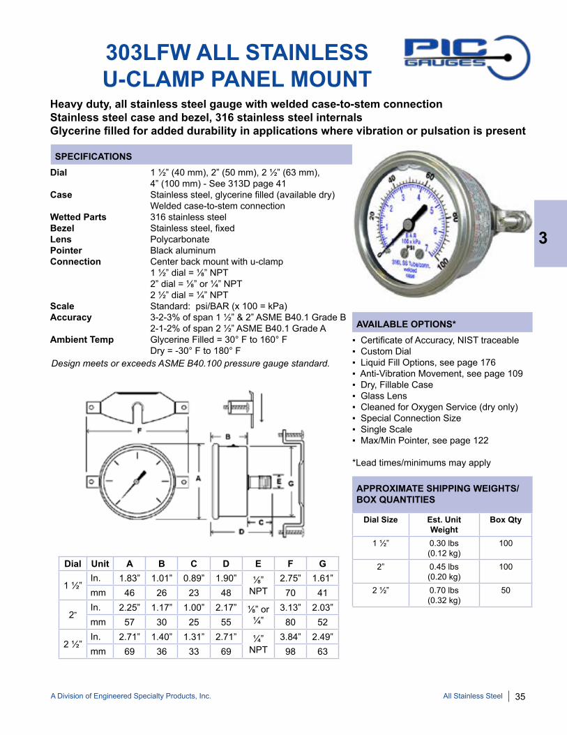
303LFW ALL STAINLESSU-CLAMP PANEL MOUNT
Dial 1 ½” (40 mm), 2” (50 mm), 2 ½” (63 mm), 4” (100 mm) - See 313D page 41Case Stainless steel, glycerine filled (available dry) Welded case-to-stem connectionWetted Parts 316 stainless steelBezel Stainless steel, fixedLens PolycarbonatePointer Black aluminumConnection Center back mount with u-clamp 1 ½” dial = ⅛” NPT 2” dial = ⅛” or ¼” NPT 2 ½” dial = ¼” NPT Scale Standard: psi/BAR (x 100 = kPa)Accuracy 3-2-3% of span 1 ½” & 2” ASME B40.1 Grade B 2-1-2% of span 2 ½” ASME B40.1 Grade AAmbient Temp Glycerine Filled = 30° F to 160° F Dry = -30° F to 180° F
Dial Size Est. Unit Weight
Box Qty
1 ½” 0.30 lbs(0.12 kg)
100
2” 0.45 lbs(0.20 kg)
100
2 ½” 0.70 lbs(0.32 kg)
50
Dial Unit A B C D E F G
1 ½”In. 1.83” 1.01” 0.89” 1.90” ⅛”
NPT2.75” 1.61”
mm 46 26 23 48 70 41
2”In. 2.25” 1.17” 1.00” 2.17” ⅛” or
¼”3.13” 2.03”
mm 57 30 25 55 80 52
2 ½” In. 2.71” 1.40” 1.31” 2.71” ¼”
NPT3.84” 2.49”
mm 69 36 33 69 98 63
3
All Stainless Steel
Heavy duty, all stainless steel gauge with welded case-to-stem connectionStainless steel case and bezel, 316 stainless steel internalsGlycerine filled for added durability in applications where vibration or pulsation is present
▪ Certificate of Accuracy, NIST traceable ▪ Custom Dial▪ Liquid Fill Options, see page 176▪ Anti-Vibration Movement, see page 109▪ Dry, Fillable Case▪ Glass Lens▪ Cleaned for Oxygen Service (dry only)▪ Special Connection Size▪ Single Scale▪ Max/Min Pointer, see page 122
*Lead times/minimums may apply
Design meets or exceeds ASME B40.100 pressure gauge standard.
36 A Division of Engineered Specialty Products, Inc.
AVAILABLE OPTIONS*
APPROXIMATE SHIPPING WEIGHTS/BOX QUANTITIES
SPECIFICATIONS
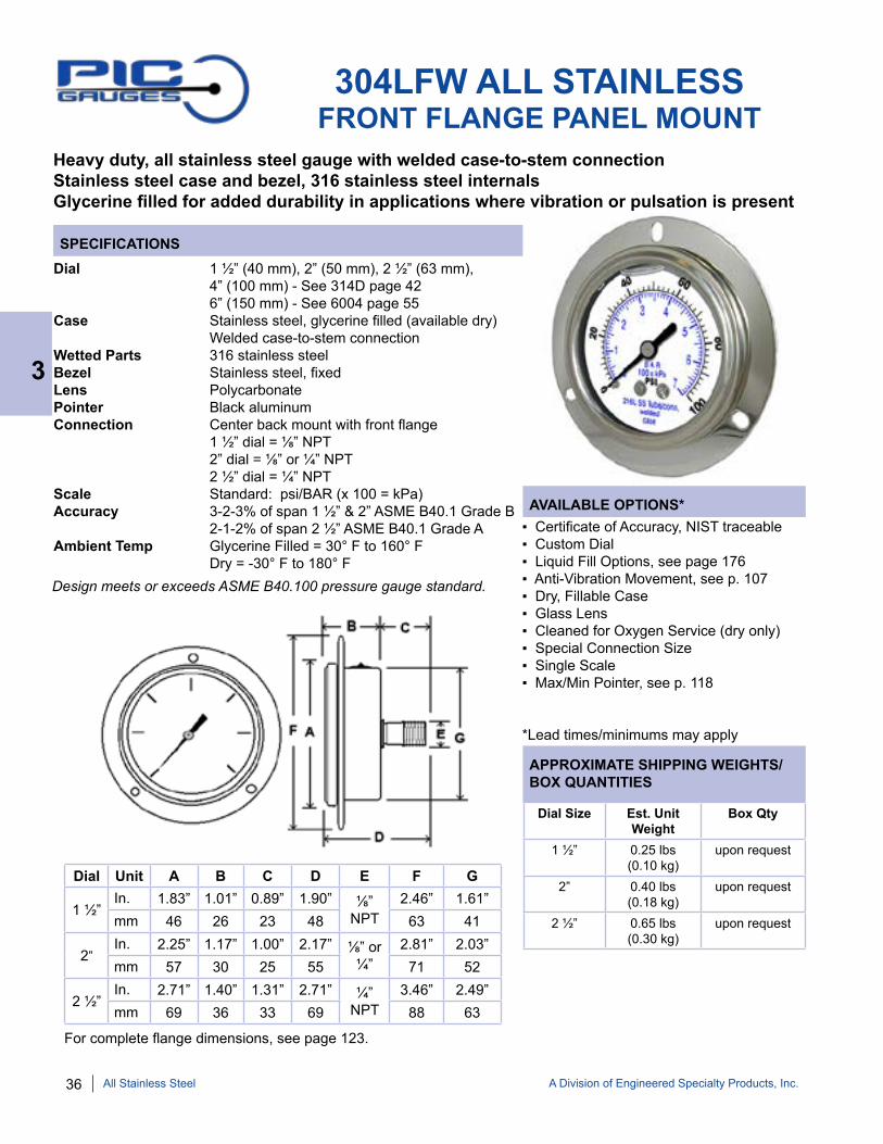
304LFW ALL STAINLESS FRONT FLANGE PANEL MOUNT
Dial 1 ½” (40 mm), 2” (50 mm), 2 ½” (63 mm), 4” (100 mm) - See 314D page 42 6” (150 mm) - See 6004 page 55Case Stainless steel, glycerine filled (available dry) Welded case-to-stem connectionWetted Parts 316 stainless steelBezel Stainless steel, fixed Lens PolycarbonatePointer Black aluminumConnection Center back mount with front flange 1 ½” dial = ⅛” NPT 2” dial = ⅛” or ¼” NPT 2 ½” dial = ¼” NPTScale Standard: psi/BAR (x 100 = kPa)Accuracy 3-2-3% of span 1 ½” & 2” ASME B40.1 Grade B 2-1-2% of span 2 ½” ASME B40.1 Grade AAmbient Temp Glycerine Filled = 30° F to 160° F Dry = -30° F to 180° F
Dial Size Est. Unit Weight
Box Qty
1 ½” 0.25 lbs(0.10 kg)
upon request
2” 0.40 lbs(0.18 kg)
upon request
2 ½” 0.65 lbs(0.30 kg)
upon request
Dial Unit A B C D E F G
1 ½”In. 1.83” 1.01” 0.89” 1.90” ⅛”
NPT2.46” 1.61”
mm 46 26 23 48 63 41
2”In. 2.25” 1.17” 1.00” 2.17” ⅛” or
¼”2.81” 2.03”
mm 57 30 25 55 71 52
2 ½” In. 2.71” 1.40” 1.31” 2.71” ¼”
NPT3.46” 2.49”
mm 69 36 33 69 88 63
3
All Stainless Steel
For complete flange dimensions, see page 123.
▪ Certificate of Accuracy, NIST traceable▪ Custom Dial ▪ Liquid Fill Options, see page 176▪ Anti-Vibration Movement, see p. 107▪ Dry, Fillable Case▪ Glass Lens▪ Cleaned for Oxygen Service (dry only)▪ Special Connection Size▪ Single Scale▪ Max/Min Pointer, see p. 118
*Lead times/minimums may apply
Design meets or exceeds ASME B40.100 pressure gauge standard.
Heavy duty, all stainless steel gauge with welded case-to-stem connectionStainless steel case and bezel, 316 stainless steel internalsGlycerine filled for added durability in applications where vibration or pulsation is present
A Division of Engineered Specialty Products, Inc. 37
AVAILABLE OPTIONS*
SPECIFICATIONS
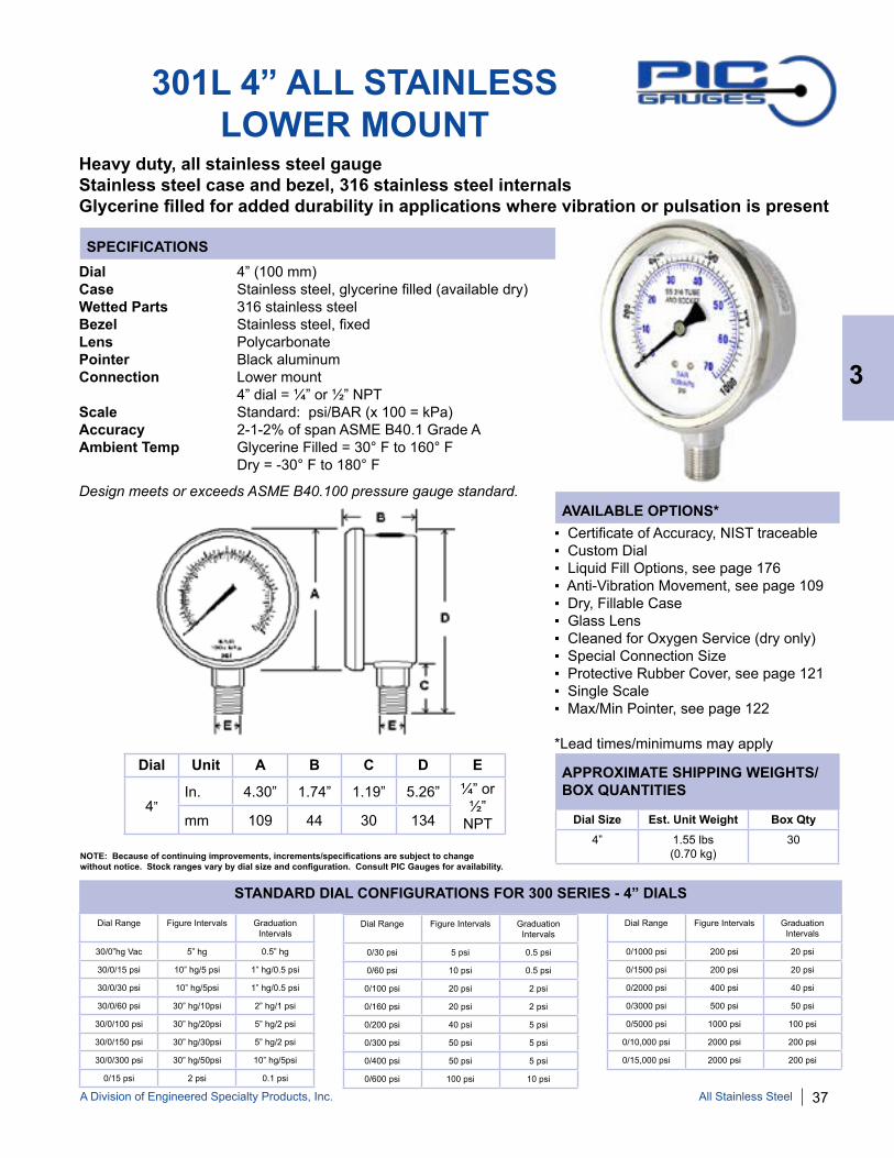
301L 4” ALL STAINLESSLOWER MOUNT
Dial 4” (100 mm)Case Stainless steel, glycerine filled (available dry)Wetted Parts 316 stainless steelBezel Stainless steel, fixedLens PolycarbonatePointer Black aluminumConnection Lower mount 4” dial = ¼” or ½” NPTScale Standard: psi/BAR (x 100 = kPa)Accuracy 2-1-2% of span ASME B40.1 Grade AAmbient Temp Glycerine Filled = 30° F to 160° F Dry = -30° F to 180° F
▪ Certificate of Accuracy, NIST traceable▪ Custom Dial▪ Liquid Fill Options, see page 176▪ Anti-Vibration Movement, see page 109▪ Dry, Fillable Case▪ Glass Lens▪ Cleaned for Oxygen Service (dry only)▪ Special Connection Size▪ Protective Rubber Cover, see page 121▪ Single Scale ▪ Max/Min Pointer, see page 122
*Lead times/minimums may apply
All Stainless Steel
Heavy duty, all stainless steel gauge Stainless steel case and bezel, 316 stainless steel internalsGlycerine filled for added durability in applications where vibration or pulsation is present
Design meets or exceeds ASME B40.100 pressure gauge standard.
3
APPROXIMATE SHIPPING WEIGHTS/BOX QUANTITIES
Dial Unit A B C D E
4” In. 4.30” 1.74” 1.19” 5.26” ¼” or
½” NPTmm 109 44 30 134 Dial Size Est. Unit Weight Box Qty
4” 1.55 lbs(0.70 kg)
30NOTE: Because of continuing improvements, increments/specifications are subject to change without notice. Stock ranges vary by dial size and configuration. Consult PIC Gauges for availability.
Dial Range Figure Intervals Graduation Intervals
30/0”hg Vac 5” hg 0.5” hg
30/0/15 psi 10” hg/5 psi 1” hg/0.5 psi
30/0/30 psi 10” hg/5psi 1” hg/0.5 psi
30/0/60 psi 30” hg/10psi 2” hg/1 psi
30/0/100 psi 30” hg/20psi 5” hg/2 psi
30/0/150 psi 30” hg/30psi 5” hg/2 psi
30/0/300 psi 30” hg/50psi 10” hg/5psi
0/15 psi 2 psi 0.1 psi
Dial Range Figure Intervals Graduation Intervals
0/30 psi 5 psi 0.5 psi
0/60 psi 10 psi 0.5 psi
0/100 psi 20 psi 2 psi
0/160 psi 20 psi 2 psi
0/200 psi 40 psi 5 psi
0/300 psi 50 psi 5 psi
0/400 psi 50 psi 5 psi
0/600 psi 100 psi 10 psi
Dial Range Figure Intervals Graduation Intervals
0/1000 psi 200 psi 20 psi
0/1500 psi 200 psi 20 psi
0/2000 psi 400 psi 40 psi
0/3000 psi 500 psi 50 psi
0/5000 psi 1000 psi 100 psi
0/10,000 psi 2000 psi 200 psi
0/15,000 psi 2000 psi 200 psi
STANDARD DIAL CONFIGURATIONS FOR 300 SERIES - 4” DIALS

38 A Division of Engineered Specialty Products, Inc.
310 SERIES ALL STAINLESS
Heavy duty, all stainless steel gauge with removable bezel, adjustable pointer1% accuracy, welded case-to-stem connection, dry yet fillable
Dial Range
Figure Intervals
Graduation Intervals
30/0”hg Vac 5” hg 0.5” hg
30/0/15 psi 10” hg/5 psi 1” hg/0.5 psi
30/0/30 psi 10” hg/5 psi 1” hg/0.5 psi
30/0/60 psi 10” hg/10psi 2” hg/1 psi
30/0/100 psi 30” hg/10psi 2” hg/1 psi
30/0/150 psi 30” hg/20psi 10” hg/2 psi
30/0/300 psi 30” hg/50psi 10” hg/2 psi
0/15 psi 2 psi 0.1 psi
0/30 psi 3 psi 0.2 psi
Dial Range
Figure Intervals
Graduation Intervals
0/60 psi 5 psi 0.5 psi
0/100 psi 10 psi 1 psi
0/160 psi 20 psi 2 psi
0/200 psi 20 psi 2 psi
0/300 psi 30 psi 2 psi
0/400 psi 50 psi 5 psi
0/600 psi 50 psi 5 psi
0/800 psi 100 psi 10 psi
Dial Range
Figure Intervals
Graduation Intervals
0/1000 psi 100 psi 10 psi
0/1500 psi 200 psi 10 psi
0/2000 psi 200 psi 20 psi
0/3000 psi 500 psi 20 psi
0/5000 psi 500 psi 50 psi
0/6000 psi 500 psi 50 psi
0/10,000 psi 1000 psi 100 psi
0/15,000 psi 3000 psi 100 psiNOTE: Because of continuing improvements, increments/specifications are subject to change without notice. Stock ranges vary by dial size and configuration. Consult PIC Gauges for availability.
STANDARD DIAL CONFIGURATIONS FOR 310 SERIES
312D SERIES311D SERIES
313D SERIES 314D SERIES
All Stainless Steel
3

A Division of Engineered Specialty Products, Inc. 39
SPECIFICATIONS
AVAILABLE OPTIONS*
APPROXIMATE SHIPPING WEIGHTS/BOX QUANTITIES
311D ALL STAINLESS STEELLOWER MOUNT
Dial 2 ½” (63 mm), 4” (100 mm) - See 4001 page 50 6” (150 mm) - See 6001 page 53 4 ½”, 8” and 10” available special orderCase Stainless steel, dry yet fillable Welded case-to-stem connectionWetted Parts 316 stainless steelBezel Removable, stainless steelLens Laminated safety glassPointer Adjustable, black aluminum Connection Lower mount 2 ½” dial = ¼” NPT Scale Standard: single scale psiAccuracy 1% of span ASME B40.1 Grade 1AAmbient Temp Dry = -30° F to 180° F Glycerine Filled = 30° F to 160° F
Dial Unit A B C D E F G
2 ½” In. 2.75” 1.30” 0.91” 3.50” ¼”
NPT0.51” 0.79”
mm 70 33 23 89 13 20
Dial Size Est. Unit Weight
Box Qty
2 ½” 0.35 lbs(0.16 kg)
50
Heavy duty, all stainless steel gauge with removable bezel, adjustable pointer1% accuracy, welded case-to-stem connection, dry yet fillable
▪ Certificate of Accuracy, NIST traceable▪ Custom Dial ▪ Liquid Fill Options, see page 176▪ Anti-Vibration Movement, see page 109▪ Cleaned for Oxygen Service (dry only)▪ Special Connection Size▪ Protective Rubber Cover, see page 121▪ Plastic Lens▪ Dual Scale▪ Max/Min Pointer, see page 122
*Lead times/minimums may apply
Design meets or exceeds ASME B40.100 pressure gauge standard.
All Stainless Steel
3
40 A Division of Engineered Specialty Products, Inc.
SPECIFICATIONS
AVAILABLE OPTIONS*
APPROXIMATE SHIPPING WEIGHTS/BOX QUANTITIES
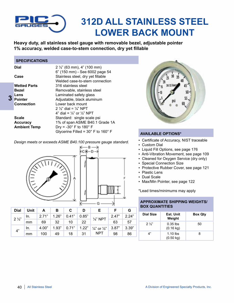
312D ALL STAINLESS STEELLOWER BACK MOUNT
Dial 2 ½” (63 mm), 4” (100 mm) 6” (150 mm) - See 6002 page 54Case Stainless steel, dry yet fillable Welded case-to-stem connectionWetted Parts 316 stainless steelBezel Removable, stainless steel Lens Laminated safety glassPointer Adjustable, black aluminum Connection Lower back mount 2 ½” dial = ¼” NPT 4” dial = ¼” or ½” NPTScale Standard: single scale psiAccuracy 1% of span ASME B40.1 Grade 1AAmbient Temp Dry = -30° F to 180° F Glycerine Filled = 30° F to 160° F
Dial Unit A B C D E F G
2 ½” In. 2.71” 1.26” 0.41” 0.85”
¼” NPT2.47” 2.24”
mm 69 32 10 22 63 57
4”In. 4.00” 1.93” 0.71” 1.22” ¼” or ½”
NPT3.87” 3.39”
mm 100 49 18 31 98 86
Dial Size Est. Unit Weight
Box Qty
2 ½” 0.35 lbs(0.16 kg)
50
4” 1.10 lbs(0.50 kg)
8
Heavy duty, all stainless steel gauge with removable bezel, adjustable pointer1% accuracy, welded case-to-stem connection, dry yet fillable
▪ Certificate of Accuracy, NIST traceable▪ Custom Dial▪ Liquid Fill Options, see page 176▪ Anti-Vibration Movement, see page 109▪ Cleaned for Oxygen Service (dry only)▪ Special Connection Size▪ Protective Rubber Cover, see page 121▪ Plastic Lens▪ Dual Scale▪ Max/Min Pointer, see page 122
*Lead times/minimums may apply
Design meets or exceeds ASME B40.100 pressure gauge standard.
All Stainless Steel
3

A Division of Engineered Specialty Products, Inc. 41
SPECIFICATIONS
AVAILABLE OPTIONS*
APPROXIMATE SHIPPING WEIGHTS/BOX QUANTITIES
313D ALL STAINLESSCLAMP-RING PANEL MOUNT
Dial 2 ½” (63 mm), 4” (100 mm)Case Stainless steel, dry yet fillable Welded case-to-stem connectionWetted Parts 316 stainless steelBezel Removable, stainless steel Lens Laminated safety glassPointer Adjustable, black aluminum Connection Lower back mount with clamp-ring 2 ½” dial = ¼” NPT 4” dial = ¼” or ½” NPTScale Standard: single scale psiAccuracy 1% of span ASME B40.1 Grade 1AAmbient Temp Dry = -30° F to 180° F Glycerine Filled = 30° F to 160° F
Dial Unit A B C D E F G H I
2 ½” In. 2.71” 1.26” 0.41” 0.85” ¼”
NPT2.47” 2.24” 2.65” 3.23”
mm 69 32 10 22 63 57 67 82
4”In. 4.00” 1.93” 0.71” 1.22” ¼” or
½”3.87” 3.39” 5.13” 5.13”
mm 100 49 18 31 98 86 130 130
Dial Size Est. Unit Weight
Box Qty
2 ½” 0.60 lbs(0.26 kg)
50
4” 1.20 lbs(0.54 kg)
8
2.5” Clamp-Ring 4.0” Clamp-Ring
Heavy duty, all stainless steel gauge with removable bezel, adjustable pointer1% accuracy, welded case-to-stem connection, dry yet fillable
▪ Certificate of Accuracy, NIST traceable▪ Custom Dial▪ Liquid Fill Options, see page 176▪ Anti-Vibration Movement, see page 109▪ Cleaned for Oxygen Service (dry only)▪ Special Connection Size▪ Plastic Lens▪ Dual Scale▪ Max/Min Pointer, see page 122
*Lead times/minimums may apply
Design meets or exceeds ASME B40.100 pressure gauge standard.
All Stainless Steel
3

42 A Division of Engineered Specialty Products, Inc.
SPECIFICATIONS
AVAILABLE OPTIONS*
APPROXIMATE SHIPPING WEIGHTS/BOX QUANTITIES
314D ALL STAINLESS STEELFRONT FLANGE PANEL MOUNT
Dial 2 ½” (63 mm), 4” (100 mm), 6” (150 mm) - See 6004 page 55Case Stainless steel, dry yet fillable Welded case-to-stem connectionWetted Parts 316 stainless steelBezel Removable, stainless steel Lens Laminated safety glassPointer Adjustable, black aluminum Connection Lower back mount with front flange 2 ½” dial = ¼” NPT 4” dial = ¼” or ½” NPTScale Standard: single scale psiAccuracy 1% of span ASME B40.1 Grade 1AAmbient Temp Dry = -30° F to 180° F Glycerine Filled = 30° F to 160° F
Dial Unit A B C D E F H
2 ½” In. 2.71” 1.23” 1.00” 2.23” ¼”
NPT3.45” 2.45”
mm 69 31 25 57 88 62
4”In. 4.03” 1.97” 1.48” 3.45” ¼” or
½”5.22” 3.86”
mm 102 50 38 88 133 98G Dimensions (Screw Holes)
Dial Arc Unit Distance from ctr Size (oblong)
2 ½” 120°In. 1.58” 0.18” x 0.25”mm 40 4.5 x 6.5
4” 120°In. 2.25” 0.18” (round)mm 57.3 4.5 (round)
Dial Size Est. Unit Weight
Box Qty
2 ½” 0.60 lbs(0.26 kg)
50
4” 1.20 lbs(0.54 kg)
8
Heavy duty, all stainless steel gauge with removable bezel, adjustable pointer1% accuracy, welded case-to-stem connection, dry yet fillable
For complete flange dimensions, see page 123.
▪ Certificate of Accuracy, NIST traceable ▪ Custom Dial▪ Liquid Fill Options, see page 176▪ Anti-Vibration Movement, see page 109▪ Cleaned for Oxygen Service (dry only)▪ Special Connection Size▪ Plastic Lens▪ Dual Scale▪ Max/Min Pointer, see page 122
*Lead times/minimums may apply
Design meets or exceeds ASME B40.100 pressure gauge standard.
All Stainless Steel
3

A Division of Engineered Specialty Products, Inc. 43
AVAILABLE OPTIONS*
APPROXIMATE SHIPPING WEIGHTS/BOX QUANTITIES
SPECIFICATIONS
S301L HEAVY DUTY 4”ALL STAINLESS LOWER MOUNTHeavy duty, all stainless steel gauge with welded case-to-stem connectionStainless steel case and bezel, 316 stainless steel internalsGlycerine filled for added durability in applications where vibration or pulsation is present
Dial 4” (100 mm)Case Stainless steel, glycerine filledWetted Parts 316 stainless steelBezel Stainless steel, fixedLens PolycarbonatePointer Black aluminumConnection Lower mount 4” dial = ¼” or ½” NPTScale Standard: single scale psiAccuracy 1% of span ASME B40.1 Grade 1AAmbient Temp Glycerine Filled = 30° F to 160° F Dry = -30° F to 180° F
▪ Certificate of Accuracy, NIST traceable▪ Custom Dial▪ Liquid Fill Options, see page 177▪ Anti-Vibration Movement, see page 109▪ Cleaned for Oxygen Service (dry only)▪ Special Connection Size▪ Protective Rubber Cover, see page 121▪ Max/Min Pointer, see page 122
*Lead times/minimums may apply
Dial Size Est. Unit Weight
Box Qty
4” 1.55 lbs(0.70 kg)
20
Dial Unit A B C D E
4”In. 4.07” 1.94” 1.46” 5.32” ¼” or
½” NPTmm 103 49 37 135
Dial Range
Figure Intervals
Graduation Intervals
30/0”hg Vac 3” hg 0.2” hg
0/15 psi 1 psi 0.1 psi
0/30 psi 3 psi 0.2 psi
0/60 psi 5 psi 0.5 psi
0/100 psi 10 psi 1 psi
0/160 psi 20 psi 2 psi
0/200 psi 20 psi 2 psi
0/300 psi 30 psi 2 psi
0/400 psi 50 psi 5 psi
Dial Range
Figure Intervals
Graduation Intervals
0/600 psi 50 psi 5 psi
0/1000 psi 100 psi 10 psi
0/1500 psi 200 psi 10 psi
0/2000 psi 200 psi 20 psi
0/3000 psi 500 psi 20 psi
0/5000 psi 500 psi 50 psi
0/6000 psi 500 psi 50 psi
0/10,000 psi 1000 psi 100 psi
0/15,000 psi 3,000 psi 100 psi
STANDARD DIAL CONFIGURATIONS
NOTE: Because of continuing improvements, increments/specifica-tions are subject to change without notice. Stock ranges vary by dial size and configuration. Consult PIC Gauges for availability.
Design meets or exceeds ASME B40.100 pressure gauge standard.
All Stainless Steel
3

44 A Division of Engineered Specialty Products, Inc.
SEC-300LFW SERIES ALL STAINLESS STEEL
SEC-302LFW SERIESSEC-301LFW SERIES
SEC-303LFW SERIES SEC-304LFW SERIES
Dial Range
Figure Intervals
Graduation Intervals
30/0”hg Vac 5” hg 0.5” hg
30/0/30 psi 10” hg/10psi 1” hg/1 psi
30/0/150 psi 10” hg/30psi 1” hg/2 psi
0/15 psi 3 psi 0.2 psi
0/30 psi 5 psi 0.5 psi
0/60 psi 10 psi 1 psi
Dial Range
Figure Intervals
Graduation Intervals
0/100 psi 20 psi 2 psi
0/160 psi 20 psi 2 psi
0/200 psi 40 psi 5 psi
0/300 psi 50 psi 5 psi
0/400 psi 100 psi 10 psi
0/600 psi 100 psi 10 psi
Dial Range
Figure Intervals
Graduation Intervals
0/1000 psi 200 psi 10 psi
0/2000 psi 400 psi 50 psi
0/3000 psi 500 psi 50 psi
0/5000 psi 1000 psi 100 psi
0/10,000 psi 2000 psi 200 psi
NOTE: Because of continuing improvements, increments/specifications are subject to change without notice. Stock ranges vary by dial size and configuration. Consult PIC Gauges for availability.
STANDARD DIAL CONFIGURATIONS FOR SEC-300LFW SERIES
All stainless steel gauge with welded case-to-stem connectionStainless steel case and bezel, 316 stainless steel internalsGlycerine filled for added durability in applications where vibration or pulsation is present
All Stainless Steel
3
A Division of Engineered Specialty Products, Inc. 45
SPECIFICATIONS
AVAILABLE OPTIONS*
APPROXIMATE SHIPPING WEIGHTS/BOX QUANTITIES
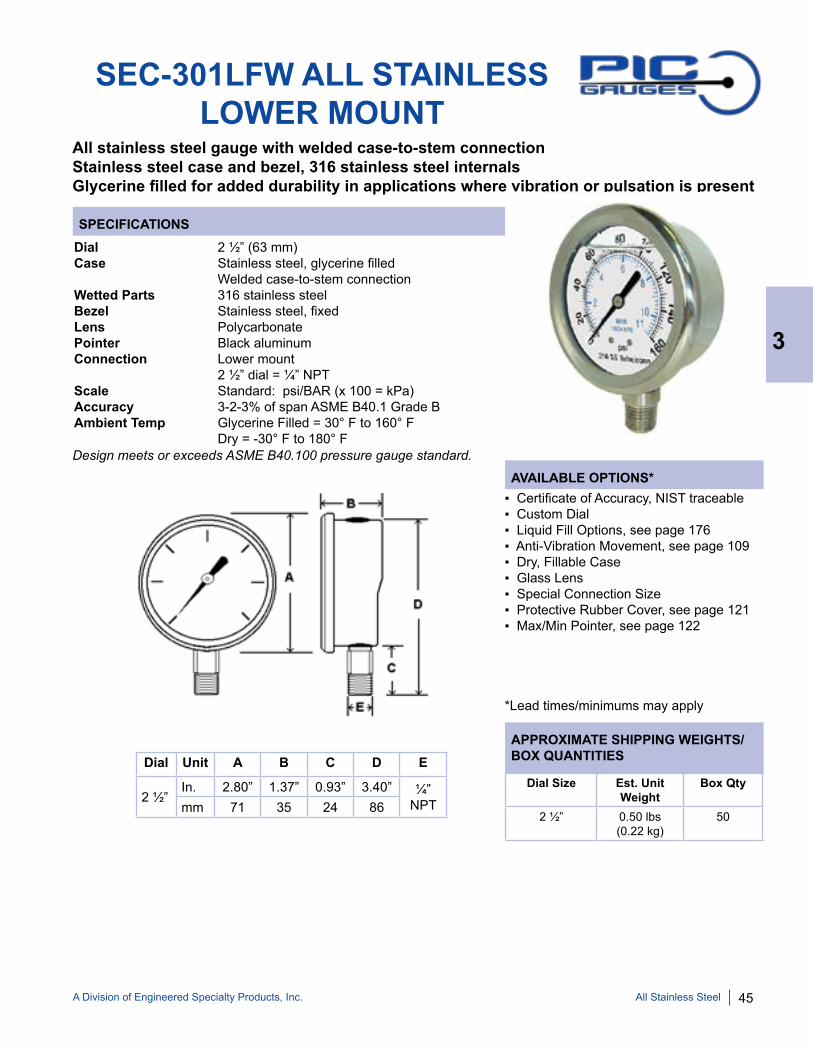
SEC-301LFW ALL STAINLESSLOWER MOUNT
All stainless steel gauge with welded case-to-stem connectionStainless steel case and bezel, 316 stainless steel internalsGlycerine filled for added durability in applications where vibration or pulsation is present
Dial 2 ½” (63 mm)Case Stainless steel, glycerine filled Welded case-to-stem connectionWetted Parts 316 stainless steelBezel Stainless steel, fixedLens PolycarbonatePointer Black aluminumConnection Lower mount 2 ½” dial = ¼” NPTScale Standard: psi/BAR (x 100 = kPa)Accuracy 3-2-3% of span ASME B40.1 Grade BAmbient Temp Glycerine Filled = 30° F to 160° F Dry = -30° F to 180° F
Dial Size Est. Unit Weight
Box Qty
2 ½” 0.50 lbs(0.22 kg)
50
Dial Unit A B C D E
2 ½”In. 2.80” 1.37” 0.93” 3.40” ¼”
NPTmm 71 35 24 86
▪ Certificate of Accuracy, NIST traceable▪ Custom Dial▪ Liquid Fill Options, see page 176▪ Anti-Vibration Movement, see page 109▪ Dry, Fillable Case▪ Glass Lens▪ Special Connection Size▪ Protective Rubber Cover, see page 121▪ Max/Min Pointer, see page 122
*Lead times/minimums may apply
Design meets or exceeds ASME B40.100 pressure gauge standard.
All Stainless Steel
3

46 A Division of Engineered Specialty Products, Inc.
SPECIFICATIONS
AVAILABLE OPTIONS*
APPROXIMATE SHIPPING WEIGHTS/BOX QUANTITIES
SEC-302LFW ALL STAINLESSCENTER BACK MOUNT
Dial 2 ½” (63 mm)Case Stainless steel, glycerine filled Welded case-to-stem connectionWetted Parts 316 stainless steelBezel Stainless steel, fixedLens Polycarbonate Pointer Black aluminumConnection Center back mount 2 ½” dial = ¼” NPT Scale Standard: psi/BAR (x 100 = kPa)Accuracy 3-2-3% of span ASME B40.1 Grade BAmbient Temp Glycerine Filled = 30° F to 160° F Dry = -30° F to 180° F
Dial Unit A B C D E
2 ½” In. 2.67” 1.17” 1.08” 2.19” ¼”
NPTmm 68 30 28 56
Dial Size Est. Unit Weight
Box Qty
2 ½” 0.45 lbs(0.22 kg)
50
All stainless steel gauge with welded case-to-stem connectionStainless steel case and bezel, 316 stainless steel internalsGlycerine filled for added durability in applications where vibration or pulsation is present
▪ Certificate of Accuracy, NIST traceable▪ Custom Dial▪ Liquid Fill Options, see page 176▪ Anti-Vibration Movement, see page 109▪ Dry, Fillable Case▪ Glass Lens▪ Special Connection Size▪ Protective Rubber Cover, see page 121▪ Max/Min Pointer, see page 122
*Lead times/minimums may apply
Design meets or exceeds ASME B40.100 pressure gauge standard.
All Stainless Steel
3

A Division of Engineered Specialty Products, Inc. 47
SPECIFICATIONS
AVAILABLE OPTIONS*
APPROXIMATE SHIPPING WEIGHTS/BOX QUANTITIES
SEC-303LFW ALL STAINLESSU-CLAMP PANEL MOUNT
Dial 2 ½” (63 mm)Case Stainless steel, glycerine filled Welded case-to-stem connectionWetted Parts 316 stainless steelBezel Stainless steel, fixedLens PolycarbonatePointer Black aluminumConnection Center back mount with u-clamp 2 ½” dial = ¼” NPTScale Standard: psi/BAR (x 100 = kPa)Accuracy 3-2-3% of span ASME B40.1 Grade BAmbient Temp Glycerine Filled = 30° F to 160° F Dry = -30° F to 180° F
Dial Unit A B C D E F G
2 ½”In. 2.67” 1.17” 1.08” 2.19” ¼”
NPT3.84” 2.45”
mm 68 30 28 56 98 62
Dial Size Est. Unit Weight
Box Qty
2 ½” 0.55 lbs(0.26 kg)
50
All stainless steel gauge with welded case-to-stem connectionStainless steel case and bezel, 316 stainless steel internalsGlycerine filled for added durability in applications where vibration or pulsation is present
▪ Certificate of Accuracy, NIST traceable▪ Custom Dial▪ Liquid Fill Options, see page 176▪ Anti-Vibration Movement, see page 109▪ Dry, Fillable Case▪ Glass Lens▪ Special Connection Size▪ Max/Min Pointer, see page 122
*Lead times/minimums may apply
Design meets or exceeds ASME B40.100 pressure gauge standard.
All Stainless Steel
3

48 A Division of Engineered Specialty Products, Inc.
SPECIFICATIONS
AVAILABLE OPTIONS*
APPROXIMATE SHIPPING WEIGHTS/BOX QUANTITIES
SEC-304LFW ALL STAINLESSFRONT FLANGE PANEL MOUNT
Dial 2 ½” (63 mm)Case Stainless steel, glycerine filled Welded case-to-stem connectionWetted Parts 316 stainless steelBezel Stainless steel, fixedLens Polycarbonate Pointer Black aluminumConnection Center back mount with front flange 2 ½” dial = ¼” NPTScale Standard: psi/BAR (x 100 = kPa)Accuracy 3-2-3% of span ASME B40.1 Grade BAmbient Temp Glycerine Filled = 30° F to 160° F Dry = -30° F to 180° F
Dial Unit A B C D E F G
2 ½” In. 2.67” 1.17” 1.08” 2.19” ¼”
NPT3.46” 2.45”
mm 68 30 28 56 88 62
Dial Size Est. Unit Weight
Box Qty
2 ½” 0.50 lbs(0.24 kg)
50
For complete flange dimensions, see page 123.
All stainless steel gauge with welded case-to-stem connectionStainless steel case and bezel, 316 stainless steel internalsGlycerine filled for added durability in applications where vibration or pulsation is present
▪ Certificate of Accuracy, NIST traceable▪ Custom Dial▪ Liquid Fill Options, see page 176▪ Anti-Vibration Movement, see page 109▪ Dry, Fillable Case▪ Glass Lens▪ Special Connection Size▪ Max/Min Pointer, see page 122
*Lead times/minimums may apply
Design meets or exceeds ASME B40.100 pressure gauge standard.
All Stainless Steel
3

A Division of Engineered Specialty Products, Inc. 49
HEAVY DUTY/PROCESS GAUGEPART NUMBERING SYSTEM
DIAL SIZE/SERIES
40 = 4” Diameter - SS Case 45 = 4 ½” Diameter - Phenolic Case 60 = 6” Diameter - SS Case 65 = 6” Diameter Hinged Aluminum Case
TUBE & SOCKET
0 = 316 Stainless Steel 2 = Monel
1 = Lower Mount, Stem or Wall 1-SC = 4 ½” SS Safety Case Lower Mount 2 = Lower Back Mount 4 = Lower Back Mount, Front Flange Panel Mount 5 = Lower Mount, Back Flange 9 = Lower Back Mount, Back Flange
CASE DESIGN/MOUNTING
CONNECTION
2 = ½” NPT Male 4 = ¼” NPT Male 9 = 9/16-18 MP Male
CONN. LOCATION
L = Lower Mount R = Lower Back Mount
RANGE
A = 30/0” Hg Vac CB = 30” Hg Vac/0/15 psi CC = 30” Hg Vac/0/30 psi CD = 30” Hg Vac/0/60 psi CE = 30” Hg Vac/0/100 psi CF = 30” Hg Vac/0/150 psi CG = 30” Hg Vac/0/200 psi CH = 30” Hg Vac/0/300 psi B = 0/15 psi C = 0/30 psi D = 0/60 psi E = 0/100 psi F = 0/160 psi G = 0/200 psi H = 0/300 psi I = 0/400 psi K = 0/600 psi L = 0/800 psi M = 0/1000 psi N = 0/1500 psi O = 0/2000 psi P = 0/3000 psi R = 0/5000 psi S = 0/6000 psi U = 0/10,000 psi V = 0/15,000 psi W = 0/20,000 psi X = 0/30,000 psi
EXAMPLE: “4501-4LE-GF”
45 = 4 ½” Diameter Dial Size 0 = 316 Stainless Steel Tube & Socket 1 = Lower Mount
4 = ¼” NPT male L = Lower Mount E = 0/100 psi GF = Glycerine Fill
OPTIONS*
GF = Glycerine Fill SF = Silicone Fill GL = Glass Lens PT = Pressure Transmitter** RS = Restrictor Screw ST = Stainless Tag XX = Other
*For multiple options, use codes in sequence. **Only available in 4” all stainless
NOTE: Not all part numbers or options are available from stock. Consult PIC Gauges for availability.
4
Process Gauges
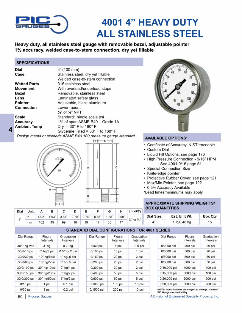
50 A Division of Engineered Specialty Products, Inc.
SPECIFICATIONS
AVAILABLE OPTIONS*
APPROXIMATE SHIPPING WEIGHTS/BOX QUANTITIES
4001 4” HEAVY DUTYALL STAINLESS STEEL
Dial 4” (100 mm)Case Stainless steel, dry yet fillable Welded case-to-stem connectionWetted Parts 316 stainless steelMovement With overload/underload stopsBezel Removable, stainless steelLens Laminated safety glassPointer Adjustable, black aluminum Connection Lower mount ¼” or ½” NPTScale Standard: single scale psiAccuracy 1% of span ASME B40.1 Grade 1AAmbient Temp Dry = -30° F to 180° F Glycerine Filled = 30° F to 160° F
▪ Certificate of Accuracy, NIST traceable▪ Custom Dial▪ Liquid Fill Options, see page 176▪ High Pressure Connection - 9/16” HPM - See 4001-9/16 page 51▪ Special Connection Size▪ Knife-edge pointer▪ Protective Rubber Cover, see page 121▪ Max/Min Pointer, see page 122▪ 0.5% Accuracy Available*Lead times/minimums may apply
Dial Size Est. Unit Wt. Box Qty4” 1 lb/0.48 kg 15
Dial Unit A B C D E F G H I (=NPT)
4”In. 4.02” 1.93” 3.87” 0.70” 0.74” 0.66” 1.38” 0.68”
¼” or ½”mm 102 49 99 18 19 17 35 17
Dial Range Figure Intervals
Graduation Intervals
30/0”hg Vac 3” hg 0.2” hg
30/0/15 psi 5” hg/3 psi 0.5”hg/.2 psi
30/0/30 psi 10” hg/5psi 1” hg/.5 psi
30/0/60 psi 10” hg/5psi 1” hg/.5 psi
30/0/100 psi 30” hg/10psi 2” hg/1 psi
30/0/150 psi 30” hg/20psi 5” hg/2 psi
30/0/300 psi 30” hg/50psi 5” hg/2 psi
0/15 psi 1 psi 0.1 psi
0/30 psi 3 psi 0.2 psi
Dial Range Figure Intervals
Graduation Intervals
0/60 psi 5 psi 0.5 psi
0/100 psi 10 psi 1 psi
0/160 psi 20 psi 2 psi
0/200 psi 20 psi 2 psi
0/300 psi 30 psi 2 psi
0/400 psi 50 psi 5 psi
0/600 psi 50 psi 5 psi
0/1000 psi 100 psi 10 psi
0/1500 psi 200 psi 10 psi
Dial Range Figure Intervals
Graduation Intervals
0/2000 psi 200 psi 20 psi
0/3000 psi 500 psi 20 psi
0/5000 psi 500 psi 50 psi
0/6000 psi 500 psi 50 psi
0/10,000 psi 1000 psi 100 psi
0/15,000 psi 3000 psi 100 psi
0/20,000 psi 2000 psi 200 psi
0/30,000 psi 6000 psi 200 psi
STANDARD DIAL CONFIGURATIONS FOR 4001 SERIES
NOTE: Specifications are subject to change. Consult PIC Gauges for availability.
Heavy duty, all stainless steel gauge with removable bezel, adjustable pointer1% accuracy, welded case-to-stem connection, dry yet fillable
Design meets or exceeds ASME B40.100 pressure gauge standard. 4
Process Gauges

A Division of Engineered Specialty Products, Inc. 51
SPECIFICATIONS
AVAILABLE OPTIONS*
APPROXIMATE SHIPPING WEIGHTS/BOX QUANTITIES
4001 9/16” HIGH PRESSURECONNECTION
Heavy duty, all stainless steel gauge with removable bezel, adjustable pointer1% accuracy, welded case-to-stem connection, dry yet fillable9/16” HPM connection, Ranges 10,000 psi, 15,000 psi, 20,000 psi, 30,000 psi
Dial 4” (100 mm)Case Stainless steel,dry yet fillable Welded case-to-stem connectionWetted Parts 316 stainless steelMovement With overload/underload stopsBezel Removable, stainless steel, Lens Laminated safety glassPointer Adjustable, black aluminumConnection Lower mount 9/16-18” High Pressure MaleScale Standard: single scale psiAccuracy 1% of span ASME B40.1 Grade 1AAmbient Temp Dry = -30° F to 180° F Glycerine Filled = 30° F to 160° F
▪ Certificate of Accuracy, NIST traceable▪ Custom Dial▪ Liquid Fill Options, see page 176▪ Cleaned for Oxygen Service (dry only)▪ Knife-edge pointer▪ Protective Rubber Cover, see page 121▪ With Gland/Collar▪ Max/Min Pointer, see page 122▪ 0.5% Accuracy Available
*Lead times/minimums may apply
Dial Size Est. Unit Wt. Box Qty4” 1.20 lbs
(0.54 kg)15
Dial Unit A B C D E F G H Thread
4”In. 4.00” 1.97” 3.87” 0.81” 2.45” 0.66” 3.26” 0.68” 9/16-18
MP Malemm 100 50 99 21 62 17 83 17
Part Number Dial Range Figure Intervals
Graduation Intervals
4001-9LU 0/10,000 psi 1,000 psi 100 psi
4001-9LV 0/15,000 psi 3,000 psi 100 psi
4001-9LW 0/20,000 psi 2,000 psi 200 psi
4001-9LX 0/30,000 psi 6,000 psi 200 psi
STANDARD DIAL CONFIGURATIONS FOR 4001 9/16” SERIES
NOTE: Because of continuing improvements, specifications are subject to change without notice. Stock ranges vary by dial size and configuration. Consult PIC Gauges for availability.
Design meets or exceeds ASME B40.100 pressure gauge standard. 4
Process Gauges
Part Number Description
60-2H9 Collar
60-2HM9 Gland
COLLAR GLAND
SOLD SEPARATELY

52 A Division of Engineered Specialty Products, Inc.
6000 SERIES 6” HEAVY DUTYALL STAINLESS STEEL
6002 SERIES6001 SERIES
6004 SERIES 6009 SERIES
Dial Range
Figure Intervals
Graduation Intervals
30/0”hg Vac 3” hg 0.2” hg
30/0/30 psi 10” hg/5 psi 1” hg/.5 psi
30/0/60 psi 10” hg/5 psi 1” hg/.5 psi
30/0/100 psi 30” hg/10psi 2” hg/1 psi
30/0/150 psi 30” hg/20psi 5” hg/2 psi
30/0/300 psi 30” hg/50psi 5” hg/2 psi
0/15 psi 1 psi 0.1 psi
0/30 psi 3 psi 0.2 psi
Dial Range
Figure Intervals
Graduation Intervals
0/60 psi 5 psi 0.5 psi
0/100 psi 10 psi 1 psi
0/160 psi 20 psi 2 psi
0/200 psi 20 psi 2 psi
0/300 psi 30 psi 2 psi
0/400 psi 50 psi 5 psi
0/600 psi 50 psi 5 psi
0/1000 psi 100 psi 10 psi
Dial Range
Figure Intervals
Graduation Intervals
0/1500 psi 200 psi 10 psi
0/2000 psi 200 psi 20 psi
0/3000 psi 500 psi 20 psi
0/5000 psi 500 psi 50 psi
0/6000 psi 500 psi 50 psi
0/10,000 psi 1000 psi 100 psi
0/15,000 psi 3000 psi 100 psi
NOTE: Because of continuing improvements, increments are subject to change. Stock ranges vary by dial size and configuration. Consult PIC Gauges for availability.
STANDARD DIAL CONFIGURATIONS FOR 6000 SERIES
Heavy duty, all stainless steel gauge with removable bezel, adjustable pointer1% accuracy, welded case-to-stem connection, dry yet fillable
4
Process Gauges
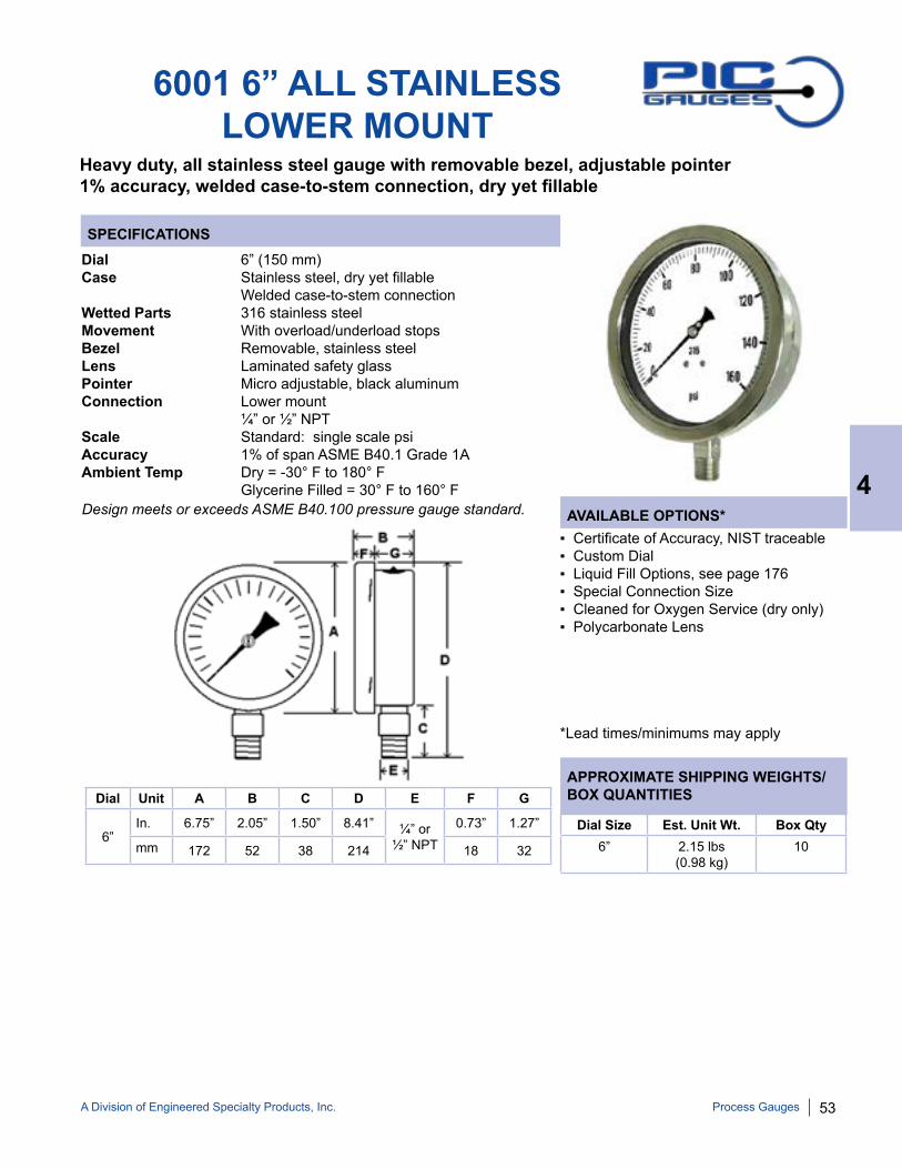
A Division of Engineered Specialty Products, Inc. 53
SPECIFICATIONS
AVAILABLE OPTIONS*
APPROXIMATE SHIPPING WEIGHTS/BOX QUANTITIES
6001 6” ALL STAINLESS LOWER MOUNT
Heavy duty, all stainless steel gauge with removable bezel, adjustable pointer1% accuracy, welded case-to-stem connection, dry yet fillable
Dial 6” (150 mm)Case Stainless steel, dry yet fillable Welded case-to-stem connectionWetted Parts 316 stainless steelMovement With overload/underload stopsBezel Removable, stainless steelLens Laminated safety glassPointer Micro adjustable, black aluminumConnection Lower mount ¼” or ½” NPTScale Standard: single scale psiAccuracy 1% of span ASME B40.1 Grade 1AAmbient Temp Dry = -30° F to 180° F Glycerine Filled = 30° F to 160° F
▪ Certificate of Accuracy, NIST traceable▪ Custom Dial▪ Liquid Fill Options, see page 176▪ Special Connection Size▪ Cleaned for Oxygen Service (dry only)▪ Polycarbonate Lens
*Lead times/minimums may apply
Dial Size Est. Unit Wt. Box Qty6” 2.15 lbs
(0.98 kg)10
Dial Unit A B C D E F G
6”In. 6.75” 2.05” 1.50” 8.41” ¼” or
½” NPT0.73” 1.27”
mm 172 52 38 214 18 32
Design meets or exceeds ASME B40.100 pressure gauge standard. 4
Process Gauges

54 A Division of Engineered Specialty Products, Inc.
SPECIFICATIONS
AVAILABLE OPTIONS*
APPROXIMATE SHIPPING WEIGHTS/BOX QUANTITIES
6002 6” ALL STAINLESS LOWER BACK MOUNT
Heavy duty, all stainless steel gauge with removable bezel, adjustable pointer1% accuracy, welded case-to-stem connection, dry yet fillable
Dial 6” (150 mm)Case Stainless steel, dry yet fillable Welded case-to-stem connectionWetted Parts 316 stainless steelMovement With overload/underload stopsBezel Removable, stainless steel Lens Laminated safety glassPointer Micro adjustable, black aluminumConnection Lower back mount ¼” NPTScale Standard: single scale psiAccuracy 1% of span ASME B40.1 Grade 1AAmbient Temp Dry = -30° F to 180° F Glycerine Filled = 30° F to 160° F
▪ Certificate of Accuracy, NIST traceable▪ Custom Dial▪ Liquid Fill Options, see page 176▪ Special Connection Size▪ Cleaned for Oxygen Service (dry only)▪ Polycarbonate Lens▪ ½” NPT or Custom Connections
*Lead times/minimums may apply
Dial Unit A B C D E F
6”In. 6.76” 2.02” 1.35” 3.37” ¼” or
½”6.24”
mm 172 52 34 86 158Dial Size Est. Unit Wt. Box Qty
6” 2.20 lbs(1.00 kg)
upon request
Design meets or exceeds ASME B40.100 pressure gauge standard. 4
Process Gauges
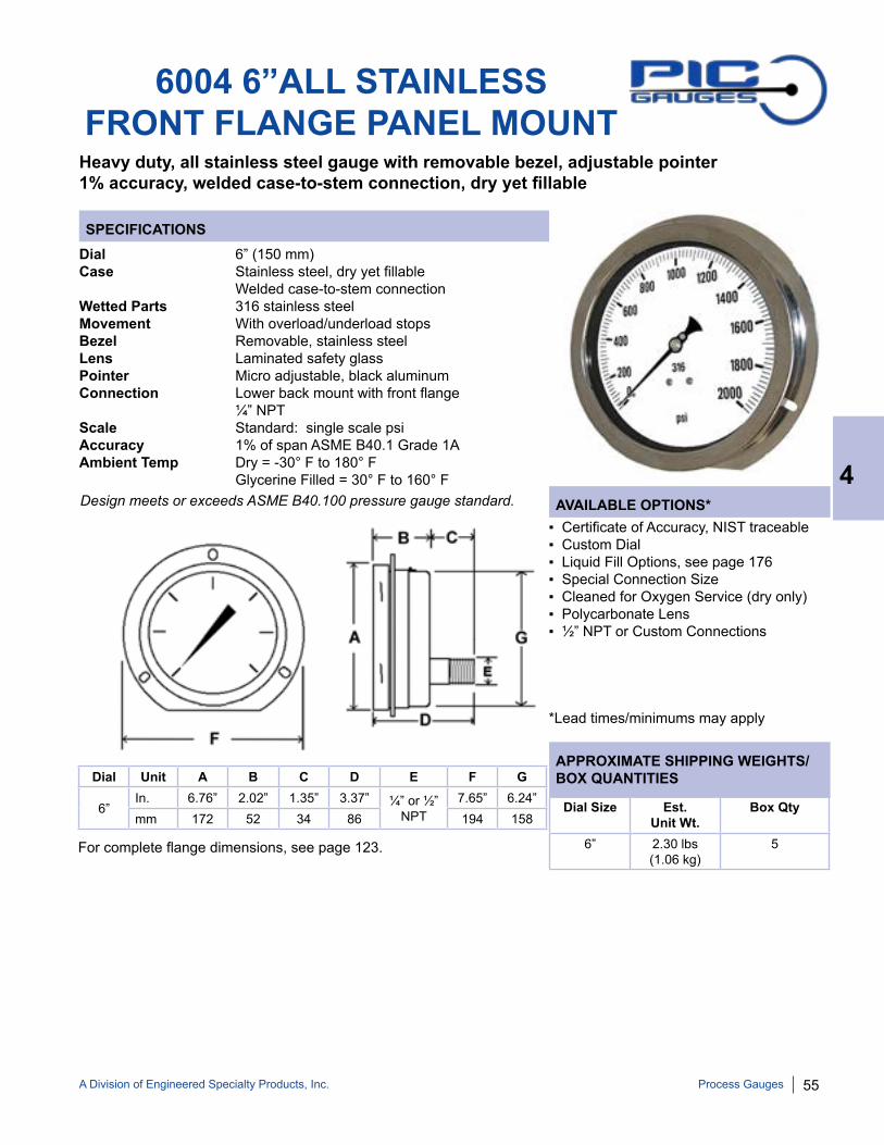
A Division of Engineered Specialty Products, Inc. 55
SPECIFICATIONS
AVAILABLE OPTIONS*
APPROXIMATE SHIPPING WEIGHTS/BOX QUANTITIES
6004 6”ALL STAINLESS FRONT FLANGE PANEL MOUNT
Heavy duty, all stainless steel gauge with removable bezel, adjustable pointer1% accuracy, welded case-to-stem connection, dry yet fillable
Dial 6” (150 mm)Case Stainless steel, dry yet fillable Welded case-to-stem connectionWetted Parts 316 stainless steelMovement With overload/underload stopsBezel Removable, stainless steelLens Laminated safety glassPointer Micro adjustable, black aluminumConnection Lower back mount with front flange ¼” NPTScale Standard: single scale psiAccuracy 1% of span ASME B40.1 Grade 1AAmbient Temp Dry = -30° F to 180° F Glycerine Filled = 30° F to 160° F
▪ Certificate of Accuracy, NIST traceable▪ Custom Dial▪ Liquid Fill Options, see page 176▪ Special Connection Size▪ Cleaned for Oxygen Service (dry only)▪ Polycarbonate Lens▪ ½” NPT or Custom Connections
*Lead times/minimums may apply
Dial Size Est. Unit Wt.
Box Qty
6” 2.30 lbs (1.06 kg)
5
Dial Unit A B C D E F G
6” In. 6.76” 2.02” 1.35” 3.37” ¼” or ½”
NPT7.65” 6.24”
mm 172 52 34 86 194 158
For complete flange dimensions, see page 123.
Design meets or exceeds ASME B40.100 pressure gauge standard. 4
Process Gauges
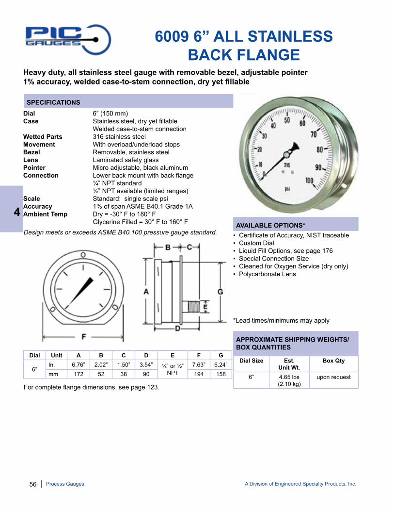
56 A Division of Engineered Specialty Products, Inc.
SPECIFICATIONS
APPROXIMATE SHIPPING WEIGHTS/BOX QUANTITIES
AVAILABLE OPTIONS*
6009 6” ALL STAINLESS BACK FLANGE
Heavy duty, all stainless steel gauge with removable bezel, adjustable pointer1% accuracy, welded case-to-stem connection, dry yet fillable
Dial 6” (150 mm)Case Stainless steel, dry yet fillable Welded case-to-stem connectionWetted Parts 316 stainless steelMovement With overload/underload stopsBezel Removable, stainless steelLens Laminated safety glassPointer Micro adjustable, black aluminumConnection Lower back mount with back flange ¼” NPT standard ½” NPT available (limited ranges)Scale Standard: single scale psiAccuracy 1% of span ASME B40.1 Grade 1AAmbient Temp Dry = -30° F to 180° F Glycerine Filled = 30° F to 160° F
▪ Certificate of Accuracy, NIST traceable▪ Custom Dial▪ Liquid Fill Options, see page 176▪ Special Connection Size▪ Cleaned for Oxygen Service (dry only)▪ Polycarbonate Lens
*Lead times/minimums may apply
Dial Size Est. Unit Wt.
Box Qty
6” 4.65 lbs (2.10 kg)
upon request
Dial Unit A B C D E F G
6” In. 6.76” 2.02” 1.50” 3.54” ¼” or ½”
NPT7.63” 6.24”
mm 172 52 38 90 194 158
For complete flange dimensions, see page 123.
Design meets or exceeds ASME B40.100 pressure gauge standard.
4
Process Gauges

A Division of Engineered Specialty Products, Inc. 57
4500 SERIESPROCESS GAUGE
Solid front/blow-out back safety case, liquid fillable316 stainless steel internals
4502 SERIES4501 SERIES
4504,6504 SERIES 4501-SC SERIES
NOTE: Because of continuing improvements, increments and specifications are subject to change. Stock ranges vary by dial size and configuration. Consult PIC Gauges for availability.
STANDARD DIAL CONFIGURATIONS FOR 4502/4504/6504/4501-SC
Dial Range
Figure Intervals
Graduation Intervals
30/0”hg Vac 5” hg 0.2” hg
30/0/30 psi 10” hg/5psi 1” hg/.5 psi
30/0/60 psi 10” hg/10psi 2” hg/1 psi
30/0/100 psi 10” hg/10psi 2” hg/1 psi
30/0/150 psi 30” hg/30psi 2” hg/2 psi
30/0/300 psi 30” hg/50psi 5” hg/5 psi
0/15 psi 3 psi 0.2 psi
0/30 psi 5 psi 0.2 psi
Dial Range
Figure Intervals
Graduation Intervals
0/60 psi 10 psi 0.5 psi
0/100 psi 10 psi 1 psi
0/160 psi 20 psi 1 psi
0/200 psi 20 psi 2 psi
0/300 psi 50 psi 2 psi
0/400 psi 50 psi 5 psi
0/600 psi 100 psi 5 psi
0/1000 psi 100 psi 10 psi
Dial Range
Figure Intervals
Graduation Intervals
0/1500 psi 250 psi 10 psi
0/2000 psi 200 psi 20 psi
0/3000 psi 500 psi 20 psi
0/5000 psi 500 psi 50 psi
0/6000 psi 500 psi 50 psi
0/10,000 psi 1000 psi 100 psi
0/15,000 psi 2500 psi 100 psi
*For 4501 series, see page 58.
4
Process Gauges

58 A Division of Engineered Specialty Products, Inc.
SPECIFICATIONS
APPROXIMATE SHIPPING WEIGHTS/BOX QUANTITIES
AVAILABLE OPTIONS*
4501 PROCESS GAUGELOWER MOUNT
Solid front/blow-out back safety case, liquid fillable316 stainless steel internals
Dial 4 ½” (114 mm)Case Phenolic case with solid front/blow out back Dry, field liquid fillable - no kit requiredWetted Parts 316 stainless steel*Movement With overload/underload stopsBezel Removable, phenolicLens PolycarbonatePointer Micro adjustable, black aluminumConnection Lower mount with back flange ¼” or ½” NPTScale Standard: single scale psiAccuracy 0.5% of span ASME B40.1 Grade 2AAmbient Temp Dry = -30° F to 180° F Glycerine Filled = 30° F to 160° F
▪ Certificate of Accuracy, NIST traceable▪ Custom Dial▪ Liquid Fill Options, see page 176▪ Special Connection Size▪ Laminated Safety Glass Lens▪ Cleaned for Oxygen Service (dry only)▪ Knife-edge Pointer▪ Max/Min Pointer, see page 122▪ Monel Internals▪ 9/16” High Pressure Connection*Lead times/minimums may apply
Dial Unit A B C D E F G NPT
4 ½” In. 5.07” 5.91” 3.03” 0.91” 1.38” 2.56” 1.38”
¼” or ½”mm 129 150 77 23 35 65 35
Dial Size Est. Unit Wt.
Box Qty
4 ½” 1.95 lbs (0.88 kg)
8
Dial Range Figure Intervals Graduation Intervals
30/0”hg Vac 3” hg 0.2” hg
30/0/15 psi 5” hg/3psi 0.5” hg/0.2 psi
30/0/30 psi 10” hg/5psi 1” hg/0.5 psi
30/0/60 psi 10” hg/5psi 1” hg/0.5 psi
30/0/100 psi 30” hg/10psi 2” hg/1 psi
30/0/150 psi 30” hg/20psi 5” hg/2 psi
30/0/200 psi 30” hg/20 psi 5” hg/2 psi
30/0/300 psi 30” hg/50psi 5” hg/2 psi
0/15 psi 1 psi 0.1 psi
Dial Range Figure Intervals Graduation Intervals
0/30 psi 3 psi 0.2 psi
0/60 psi 5 psi 0.5 psi
0/100 psi 10 psi 1 psi
0/160 psi 20 psi 2 psi
0/200 psi 20 psi 2 psi
0/300 psi 30 psi 2 psi
0/400 psi 50 psi 5 psi
0/600 psi 50 psi 5 psi
0/800 psi 100 psi 10 psi
Dial Range Figure Intervals Graduation Intervals
0/1000 psi 100 psi 10 psi
0/1500 psi 200 psi 10 psi
0/2000 psi 200 psi 20 psi
0/3000 psi 500 psi 20 psi
0/5000 psi 500 psi 50 psi
0/6000 psi 500 psi 50 psi
0/10,000 psi 1000 psi 100 psi
0/15,000 psi 3000 psi 100 psi
0/20,000 psi 2000 psi 200 psi
STANDARD DIAL CONFIGURATIONS FOR 4501
Design meets or exceeds ASME B40.100 pressure gauge standard.
NOTE: Because of continuing improvements, increments and specifications are subject to change. Stock ranges vary. Consult PIC Gauges for availability.
4
Process Gauges

A Division of Engineered Specialty Products, Inc. 59
SPECIFICATIONS
AVAILABLE OPTIONS*
APPROXIMATE SHIPPING WEIGHTS/BOX QUANTITIES
4502 PROCESS GAUGELOWER BACK MOUNT
Solid front/blow-out back safety case, liquid fillable316 stainless steel internals
Dial 4 ½” (114 mm)Case Phenolic with solid front/blow out back Dry, field liquid fillable - no kit requiredWetted Parts 316 stainless steelMovement With overload/underload stopsBezel Removable, phenolicLens PolycarbonatePointer Micro adjustable, black aluminumConnection Lower back mount with holes for wall mounting ¼” or ½” NPTScale Standard: single scale psiAccuracy 0.5% of span ASME B40.1 Grade 2AAmbient Temp Dry = -30° F to 180° F Glycerine Filled = 30° F to 160° F
▪ Certificate of Accuracy, NIST traceable▪ Custom Dial▪ Liquid Fill Options, see page 176▪ Special Connection Size▪ Laminated Safety Glass Lens▪ Cleaned for Oxygen Service (dry only)▪ Knife-edge Pointer▪ Max/Min Pointer, see page 122▪ Panel Mount Kit
*Lead times/minimums may apply
Dial Unit A B C D F G NPT
4 ½” In. 5.08" 5.84” 3.44” 1.10” 2.54” 4.27” ¼” or
½” mm 129 148 87 28 65 108
Dial Size Est. Unit Wt.
Box Qty
4 ½” 2.34 lbs/(1.06 kg)
18
Design meets or exceeds ASME B40.100 pressure gauge standard. 4
Process Gauges
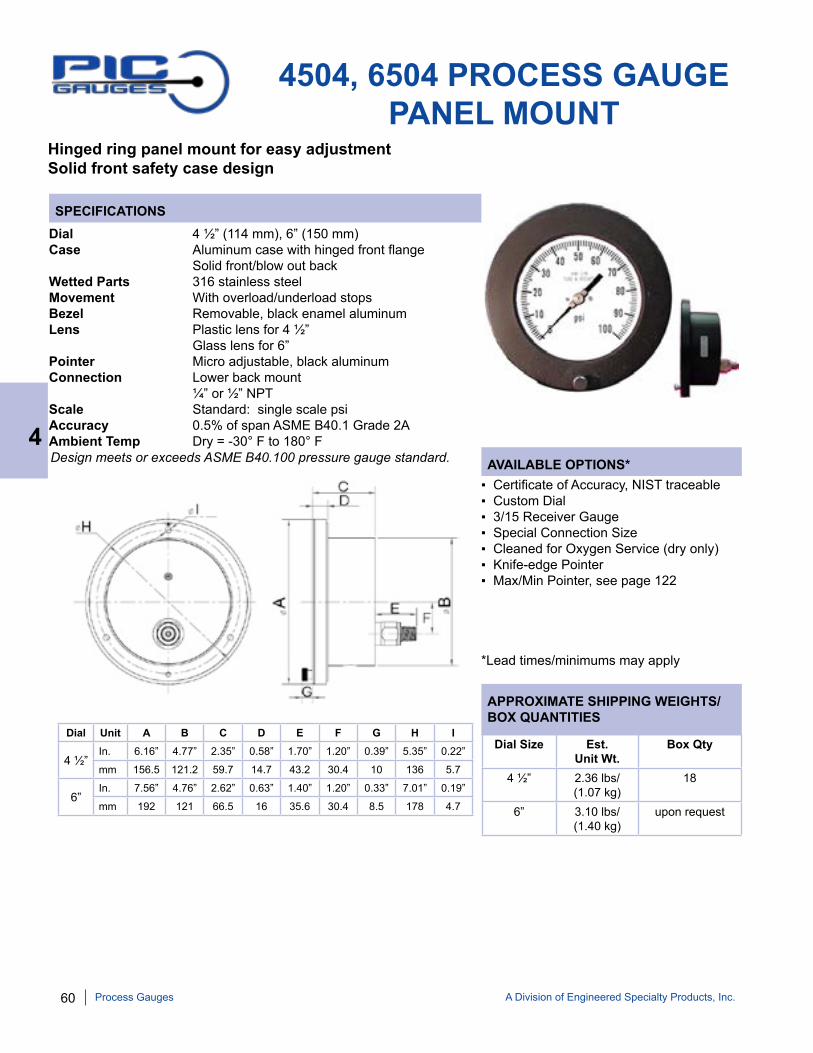
60 A Division of Engineered Specialty Products, Inc.
SPECIFICATIONS
AVAILABLE OPTIONS*
APPROXIMATE SHIPPING WEIGHTS/BOX QUANTITIES
4504, 6504 PROCESS GAUGEPANEL MOUNT
Hinged ring panel mount for easy adjustment Solid front safety case design
Dial 4 ½” (114 mm), 6” (150 mm)Case Aluminum case with hinged front flange Solid front/blow out backWetted Parts 316 stainless steelMovement With overload/underload stopsBezel Removable, black enamel aluminumLens Plastic lens for 4 ½” Glass lens for 6”Pointer Micro adjustable, black aluminumConnection Lower back mount ¼” or ½” NPTScale Standard: single scale psiAccuracy 0.5% of span ASME B40.1 Grade 2AAmbient Temp Dry = -30° F to 180° F
▪ Certificate of Accuracy, NIST traceable▪ Custom Dial▪ 3/15 Receiver Gauge▪ Special Connection Size▪ Cleaned for Oxygen Service (dry only)▪ Knife-edge Pointer▪ Max/Min Pointer, see page 122
*Lead times/minimums may apply
Dial Size Est. Unit Wt.
Box Qty
4 ½” 2.36 lbs/(1.07 kg)
18
6” 3.10 lbs/(1.40 kg)
upon request
Design meets or exceeds ASME B40.100 pressure gauge standard. 4
Process Gauges
Dial Unit A B C D E F G H I
4 ½” In. 6.16” 4.77” 2.35” 0.58” 1.70” 1.20” 0.39” 5.35” 0.22”
mm 156.5 121.2 59.7 14.7 43.2 30.4 10 136 5.7
6” In. 7.56” 4.76” 2.62” 0.63” 1.40” 1.20” 0.33” 7.01” 0.19”
mm 192 121 66.5 16 35.6 30.4 8.5 178 4.7

A Division of Engineered Specialty Products, Inc. 61
SPECIFICATIONS
AVAILABLE OPTIONS*
APPROXIMATE SHIPPING WEIGHTS/BOX QUANTITIES
4501-SC ALL STAINLESSPROCESS GAUGE
Solid front stainless steel safety case, liquid fillable316 stainless steel internals
Dial 4 ½” (114 mm)Case Stainless steel case with solid front & blow out back; Dry, liquid fillable Welded case-to-stem connectionWetted Parts 316 stainless steelMovement With overload/underload stopsBezel Removable, stainless steelLens PolycarbonatePointer Micro adjustable, black aluminum Connection Lower mount ¼” or ½” NPTScale Standard: single scale psiAccuracy 0.5% of span ASME B40.1 Grade 2AAmbient Temp Dry = -30° F to 180° F Glycerine Filled = 30° F to 160° F
▪ Certificate of Accuracy, NIST traceable▪ Custom Dial▪ Liquid Fill Options, see page 176▪ Special Connection Size▪ Laminated Safety Glass Lens▪ Cleaned for Oxygen Service (dry only)▪ Knife-edge Pointer▪ Max/Min Pointer, see page 122• 2 ½” Dial Option
*Lead times/minimums may apply
Dial Unit A B C D F G H I
4 ½” In. 5.08” 5.84” 3.44” 1.10” 2.54” 4.27” 0.75” ¼” or ½”
NPT mm 129 148 87 28 65 108 19
Dial Size Est. Unit Wt.
Box Qty
4 ½” 1.84 lbs/(0.83 kg)
27
Design meets or exceeds ASME B40.100 pressure gauge standard.
4
Process Gauges

62 A Division of Engineered Specialty Products, Inc.
SPECIFICATIONS
AVAILABLE OPTIONS*
APPROXIMATE SHIPPING WEIGHTS/BOX QUANTITIES
4
Process Gauges
4001-PT GAUGEWITH TRANSMITTER
PRESSURE GAUGEDial 4” (100 mm)Case Stainless steel Welded case-to-stem connectionWetted Parts 316L stainless steelBezel Removable, stainless steelLens Laminated safety glassPointer Adjustable, black aluminum Connection Lower mount ¼” or ½” NPTScale Standard: single scale psiAccuracy Gauge: 1% of span ASME B40.1 Grade 1AAmbient Temp -10° F to 150° F
PRESSURE TRANSMITTERSystem 2 WireSupply 24 VDCOutput 4-20 mAAccuracy 0.5% of FSElectric Wiring DIN ConnectorResponse Time 50 mSec (Typical)Sensing Element AISI 316L
▪ Certificate of Accuracy, NIST traceable▪ Custom Dial▪ Special Connection Size▪ Knife-edge pointer▪ Max/Min Pointer, see page 122▪ Electrical Contact Version
*Lead times/minimums may apply
Dial Size Est. Unit Wt. Box Qty4” 2.53 lb/1.15 kg upon
request
Dial Unit A B C I (=NPT)
4”In. 4.37” 3.51” 3.94”
¼” or ½”mm 111 89 100
Heavy duty, all stainless steel gauge with welded case-to-stem connection Solid front safety case with 4-20mA output for PLC/PID and data loggers Approved pressure transmitter
Design meets or exceeds ASME B40.100 pressure gauge standard.
Drawings are not to scale.

A Division of Engineered Specialty Products, Inc. 63
SPECIFICATIONS
AVAILABLE OPTIONS*
APPROXIMATE SHIPPING WEIGHTS/BOX QUANTITIES
601L FORGED BRASSLIQUID FILLED LOWER MOUNT
Heavy duty forged brass case and socket Glycerine filled for added durability in applications where vibration or pulsation is present
Dial 2 ½” (63 mm)Case Forged brass case & connection Glycerine filledWetted Parts Copper alloyBezel FixedLens PolycarbonatePointer Black aluminumConnection Lower mount ¼” NPTScale Standard: single scale psiAccuracy 2-1-2% of span ASME B40.1 Grade AAmbient Temp Glycerine Filled = 30° F to 160° F Dry = -30° F to 180° F
▪ Certificate of Accuracy, NIST traceable▪ Custom Dial▪ Liquid Fill Options, see page 176▪ Special Connection Size▪ Dry, fillable case▪ Protective Rubber Cover, see page 121▪ Max/Min Pointer, see page 122
*Lead times/minimums may apply
Dial Size Est. Unit Weight
Box Qty
2 ½” 0.75 lbs(0.34 kg)
50
Dial Unit A B C D E
2 ½”In. 2.58” 1.49” 0.96” 3.32”
¼” NPTmm 66 38 24 84
Dial Range
Figure Intervals
Graduation Intervals
30/0”hg Vac 5” hg 0.5” hg
30/0/30 psi 10” hg/5psi 1” hg/0.5 psi
30/0/100 psi 30” hg/10psi 2” hg/1 psi
30/0/150 psi 30” hg/20psi 2” hg/2 psi
30/0/300 psi 30” hg/50psi 10” hg/5 psi
0/15 psi 2 psi 0.1 psi
0/30 psi 5 psi 0.5 psi
0/60 psi 10 psi 1 psi
0/100 psi 10 psi 1 psi
0/160 psi 20 psi 2 psi
0/200 psi 20 psi 2 psi
Dial Range
Figure Intervals
Graduation Intervals
0/300 psi 50 psi 5 psi
0/400 psi 50 psi 5 psi
0/600 psi 50 psi 5 psi
0/1000 psi 100 psi 10 psi
0/1500 psi 200 psi 10 psi
0/2000 psi 200 psi 20 psi
0/3000 psi 500 psi 50 psi
0/5000 psi 500 psi 50 psi
0/7500 psi 1000 psi 100 psi
0/10,000 psi 1000 psi 100 psi
NOTE: Because of continuing improvements, specifications are subject to change. Stock ranges vary by dial size and configuration. Consult PIC Gauges for availability.
STANDARD DIAL CONFIGURATIONS
5
Industrial and Special Application
Design meets or exceeds ASME B40.100 pressure gauge standard.

64 A Division of Engineered Specialty Products, Inc.
SPECIFICATIONS
AVAILABLE OPTIONS*
APPROXIMATE SHIPPING WEIGHTS/BOX QUANTITIES
701L POLY CASELIQUID FILLED LOWER MOUNT
Plastic case/glycerine filled for durability in applications where vibration/pulsation is presentSuitable for air, water, oil, gas or any other media not corrosive to copper alloy
Dial 2 ½” (63 mm)Case Polypropylene, glycerine filledWetted Parts Copper alloyBezel Removable, polypropylene with adjustable Reference clipsLens PolycarbonatePointer Adjustable, black aluminum Connection Lower mount ¼” NPTScale Standard: psi/BAR (100 x kPa)Accuracy 2-1-2% of span ASME B40.1 Grade AAmbient Temp Glycerine Filled = 30° F to 160° F Dry = -30° F to 180° F
▪ Certificate of Accuracy, NIST traceable▪ Custom Dial▪ Liquid Fill Options, see page 176▪ Special Connection Size▪ Alternate Lens Material▪ Cleaned for Oxygen Service (dry only)▪ Max/Min Pointer, see page 122
*Lead times/minimums may apply
Dial Unit A B C D
2 ½” In. 3.16” 1.65” 4.25” ¼”
NPTmm 80.5 42 108
Dial Range
Figure Intervals
Graduation Intervals
30/0”hg Vac 5” hg 0.5” hg
30/0/15 psi 10” hg/5 psi 1” hg/0.5 psi
30/0/30 psi 10” hg/10psi 1” hg/1 psi
30/0/60 psi 10” hg/10psi 2” hg/1 psi
30/0/100 psi 30” hg/20 psi 5” hg/2 psi
30/0/150 psi 30” hg/20 psi 5” hg/2 psi
30/0/300 psi 30” hg/50 psi 10” hg/5 psi
0/15 psi 2 psi 0.2 psi
0/30 psi 5 psi 0.5 psi
0/60 psi 10 psi 1 psi
0/100 psi 20 psi 2 psi
Dial Range
Figure Intervals
Graduation Intervals
0/160 psi 20 psi 2 psi
0/200 psi 40 psi 5 psi
0/300 psi 50 psi 5 psi
0/400 psi 50 psi 5 psi
0/600 psi 100 psi 10 psi
0/1000 psi 200 psi 20 psi
0/1500 psi 200 psi 20 psi
0/2000 psi 400 psi 50 psi
0/3000 psi 500 psi 50 psi
0/4000 psi 500 psi 50 psi
0/5000 psi 1000 psi 100 psi
NOTE: Because of continuing improvements, specifications are subject to change. Stock ranges vary by dial size and configuration. Consult PIC Gauges for availability.
STANDARD DIAL CONFIGURATIONS
Dial Size Est. Unit Wt.
Box Qty
2 ½” 0.55 lb (0.26 kg)
upon request
5
Industrial and Special Application
For part numbering system, see page 4.
Design meets or exceeds ASME B40.100 pressure gauge standard.

A Division of Engineered Specialty Products, Inc. 65
SPECIFICATIONS
AVAILABLE OPTIONS*
APPROXIMATE SHIPPING WEIGHTS/BOX QUANTITIES
CONTRACTOR SERIES
Large, easily readable gauge designed for commercial & industrial useSuitable for air, water, oil, gas or any other media not corrosive to copper alloy
Dial 4 ½” (114 mm)Case Stainless steel, dry non-fillableWetted Parts Copper alloyBezel Removable, stainless steelLens PlasticPointer Adjustable, black aluminum Adjustment screw on dialConnection Lower mount ¼” NPTScale Standard: single scale psiAccuracy 1% of span ASME B40.1 Grade 1AAmbient Temp -30° F to 180° F
▪ Certificate of Accuracy, NIST Traceable▪ Custom Dial▪ Special Connection Size▪ Cleaned for Oxygen Service (dry only)▪ Max/Min Pointer, see page 122
*Lead times/minimums may apply
Dial Unit A B C
4 ½” In. 4.9” 1.17” .97”
mm 124 30 25
Dial Range Figure Intervals
Graduation Intervals
30/0”hg Vac 5” hg 0.5” hg
30/0/30 psi 10” hg/5psi 1” hg/1 psi
30/0/100 psi 30” hg/10psi 2” hg/1 psi
30/0/150 psi 30”hg/25 psi 5” hg/5 psi
0/15 psi 2.5 psi 0.25 psi
0/30 psi 5 psi 0.5 psi
Dial Range Figure Intervals
Graduation Intervals
0/60 psi 10 psi 1 psi
0/100 psi 10 psi 1 psi
0/160 psi 20 psi 2 psi
0/200 psi 20 psi 2 psi
0/300 psi 50 psi 5 psi
0/500 psi 50 psi 5 psi
NOTE: Because of continuing improvements, increments and specifications are subject to change. Stock ranges vary by dial size and configuration. Consult PIC Gauges for availability.
STANDARD DIAL CONFIGURATIONS
SERIES TYPE
CONTRACTOR
CONNECTION SIZE
4L = ¼” NPT
RANGE
A = 30/0” Hg Vac CC = 30” Hg Vac/0/30 psi CE = 30” Hg Vac/0/100 psi CF = 30” Hg Vac/0/150 psi B = 0/15 psi C = 0/30 psi D = 0/60 psi E = 0/100 psi F = 0/160 psi G = 0/200 psi H = 0/300 psi J = 0/500 psi
PART NUMBERING SYSTEM
Dial Size Est. Unit Wt. Box Qty4 ½” 0.75 lb/(0.36kg) upon request
5
Industrial and Special Application
Design meets or exceeds ASME B40.100 pressure gauge standard.

66 A Division of Engineered Specialty Products, Inc.
SPECIFICATIONS
AVAILABLE OPTIONS*
APPROXIMATE SHIPPING WEIGHTS/BOX QUANTITIES
115D SERIESINDUSTRIAL GAUGE
Heavy duty, easily readable gauge with removable back flangeSuitable for air, water, oil, gas or any other media not corrosive to copper alloy
Dial 4 ½” (114 mm), 6” (150 mm), 8 ½” (216 mm)Case Epoxy coated black steel With removable back flangeWetted Parts Copper alloyBezel Removable, chrome plated steelLens Plastic for 4 ½” & 6” Glass for 8 ½”Pointer Adjustable, black aluminum Connection Lower mount ¼” NPT Scale Standard: single scale psiAccuracy 1% of span ASME B40.1 Grade 1AAmbient Temp -30° F to 180° F
▪ Certificate of Accuracy, NIST traceable▪ Custom Dial▪ Special Connection Size▪ Dual Scale psi/BAR▪ Glass Lens 4 ½”, 6”
*Lead times/minimums may apply
Dial Unit A B C D E F G
4 ½” In. 4.99” 5.41” 5.87” 6.79” 1.40” 1.86” 0.18”
mm 125 138 149 172 36 47 4.5
6”In. 5.95” 6.87” 7.42” 8.41” 1.61” 1.86” 0.24”
mm 151 175 188 213 41 47 6
8 ½” In. 8.56” 9.44” 10.3” 10.8” 1.27” 1.93” 0.14”
mm 216 240 260 272 32 49 4
Dial Range
Figure Intervals
Graduation Intervals
30/0”hg Vac 5” hg 0.5” hg
30/0/30 psi 10” hg/5psi 1” hg/1 psi
30/0/60 psi 10” hg/10psi 1” hg/0.5 psi
30/0/100 psi 30” hg/20psi 2” hg/1 psi
30/0/150 psi 30” hg/20psi 5” hg/2 psi
30/0/300 psi 30” hg/50psi 5” hg/5 psi
0/15 psi 2 psi 0.2 psi
0/30 psi 5 psi 0.5 psi
Dial Range
Figure Intervals
Graduation Intervals
0/60 psi 10 psi 1 psi
0/100 psi 20 psi 1 psi
0/160 psi 20 psi 2 psi
0/200 psi 20 psi 2 psi
0/300 psi 50 psi 5 psi
0/400 psi 40 psi 5 psi
0/600 psi 100 psi 5 psi
0/1000 psi 100 psi 10 psi
NOTE: Because of continuing improvements, increments and specifications are subject to change. Stock ranges vary by dial size and configuration. Consult PIC Gauges for availability.
STANDARD DIAL CONFIGURATIONSDial Size Est. Unit Wt. Box Qty
4 ½” 1.80 lb/(0.82 kg) 106” 2.60 lb/(1.18kg) 10
8 ½” 5.55 lb/(2.52kg) upon request
Dial Size Standard Part Numbers4 ½” 115D-454(RANGE CODE)
6” 115D-604(RANGE CODE)
8 ½” 115D-854(RANGE CODE)
5
Industrial and Special Application
For range codes, see p. 4. For complete flange dimensions, see p. 123.
Design meets or exceeds ASME B40.100 pressure gauge standard.

A Division of Engineered Specialty Products, Inc. 67
LOW PRESSURE SERIESPART NUMBERING SYSTEM
SERIES TYPE
LP = Low Pressure Gauge,
MOUNTING STYLE
1 = Lower Mount 2 = Center Back Mount 3 = Back Connection, U-clamp Panel Mount 4 = Back Connection, Front Flange Panel Mount
CASE MATERIAL
BLANK = Chrome case Copper Alloy Internals SB = Stainless Steel Case Copper Alloy Internals SS = Stainless Steel Case 316 Stainless Internals PS = Phenolic Case 316 Stainless Internals
DIAL SIZE
25 = 2 ½” Diameter 40 = 4” Diameter 45 = 4 ½” Diameter
CONNECTION
4 = ¼” NPT Male 2 = ½” NPT Male
RANGE
200V = 200/0” wc Vac 160V = 160/0” wc Vac 100V = 100/0” wc Vac 60V = 60/0” wc Vac 30V = 30/0” wc Vac 15V = 15/0” wc Vac 10-WC = 0/10” wc 15 = 0/15” wc 30 = 0/30” wc 60 = 0/60” wc 100 = 0/100” wc 160 = 0/160” wc 200 = 0/200” wc 10X17.5 = 0/10 oz & 0/17.5”wc 20X35 = 0/20 oz & 0/35” wc 35X60 = 0/35 oz & 0/60” wc 60X100 = 0/60 oz & 0/100” wc 100OZ = 0/100 oz 3PSI = 0/3 psi 5PSI = 0/5 psi 10PSI = 0/10 psi 15PSI = 0/15 psi 30-0-30 = 30/0/30” wc 10-0-10 = 10/0/10” wc
EXAMPLE: “LP1-SB-254-100”
LP = Low Pressure Gauge 1 = Lower Mount SB = Stainless Steel Case, Copper Alloy Internals 25 = 2 ½” Diameter 4 = ¼” NPT Male
100 = 0/100” wc
5
Industrial and Special ApplicationNOTE: Not all part numbers or options are available from stock. Consult PIC Gauges for availability.

68 A Division of Engineered Specialty Products, Inc.
NOTE: Because of continuing improvements, increments and specifications are subject to change. Stock ranges vary by dial size and configuration. Consult PIC Gauges for availability.
LP SERIESLOW PRESSURE GAUGE
Capsule type pressure gauge for accurate measurement of low pressuresSuitable for air, water, oil, gas or any other media not corrosive to copper alloy
LP2 SERIESLP1 SERIES
LP3 SERIES LP4 SERIES
Dial Range Figure Intervals
Graduation Intervals
200/0”wc Vac 40” wc 4” wc
160/0”wc Vac 20” wc 5” wc
100/0”wc Vac 20” wc 2” wc
60/0”wc Vac 10” wc 1” wc
30/0”wc Vac 5” wc 0.5” wc
15/0”wc Vac 3” wc 0.2” wc
30/0/30” wc 10” wc 1” wc
5/0/15 wc 1” wc 0.25” wc
0/10” wc 1” wc 0.1” wc
Dial Range Figure Intervals
Graduation Intervals
0/15” wc 3” wc 0.2” wc
0/30” wc 5” wc 0.5” wc
0/20 oz & 0/35” wc
5 oz/5” wc 0.5 oz/0.5” wc
0/35 oz & 0/60” wc
5 oz/10” wc 1 oz/1” wc
0/60” wc 10” wc 1” wc
0/60 oz & 0/100” wc
10 oz/10” wc 1 oz/2” wc
0/100 oz 20 oz 2 oz
Dial Range Figure Intervals
Graduation Intervals
0/100” wc 20” wc 2” wc
0/160” wc 20” wc 5” wc
0/200” wc 40” wc 4” wc
0/3 psi 0.5 psi 0.05 psi
0/5 psi 1 psi 0.1 psi
0/10 psi 2 psi 0.2 psi
0/15 psi 3 psi 0.3 psi
STANDARD DIAL CONFIGURATIONS FOR LP SERIES
5
Industrial and Special Application
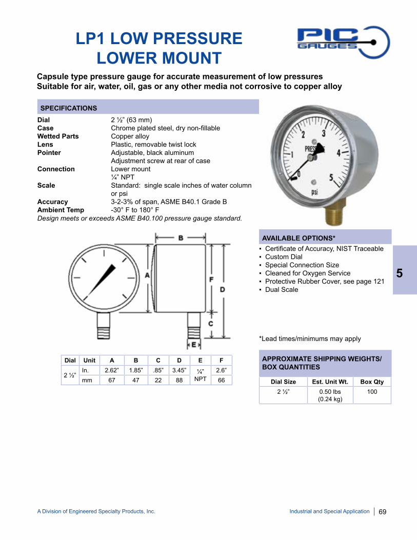
A Division of Engineered Specialty Products, Inc. 69
SPECIFICATIONS
AVAILABLE OPTIONS*
APPROXIMATE SHIPPING WEIGHTS/BOX QUANTITIES
LP1 LOW PRESSURELOWER MOUNT
Capsule type pressure gauge for accurate measurement of low pressuresSuitable for air, water, oil, gas or any other media not corrosive to copper alloy
Dial 2 ½” (63 mm)Case Chrome plated steel, dry non-fillableWetted Parts Copper alloyLens Plastic, removable twist lockPointer Adjustable, black aluminum Adjustment screw at rear of caseConnection Lower mount ¼” NPTScale Standard: single scale inches of water column or psiAccuracy 3-2-3% of span, ASME B40.1 Grade BAmbient Temp -30° F to 180° F
▪ Certificate of Accuracy, NIST Traceable▪ Custom Dial▪ Special Connection Size▪ Cleaned for Oxygen Service▪ Protective Rubber Cover, see page 121▪ Dual Scale
*Lead times/minimums may apply
Dial Size Est. Unit Wt. Box Qty2 ½” 0.50 lbs
(0.24 kg)100
Dial Unit A B C D E F
2 ½” In. 2.62” 1.85” .85” 3.45” ¼”
NPT2.6”
mm 67 47 22 88 66
5
Industrial and Special Application
Design meets or exceeds ASME B40.100 pressure gauge standard.

70 A Division of Engineered Specialty Products, Inc.
SPECIFICATIONS
AVAILABLE OPTIONS*
APPROXIMATE SHIPPING WEIGHTS/BOX QUANTITIES
LP2 LOW PRESSURECENTER BACK MOUNT
Capsule type pressure gauge for accurate measurement of low pressuresSuitable for air, water, oil, gas or any other media not corrosive to copper alloy
Dial 2 ½” (63 mm)Case Chrome plated steel, dry non-fillableWetted Parts Copper alloyLens Plastic, removable twist lockPointer Adjustable, black aluminum Adjustment screw at rear of caseConnection Center back mount ¼” NPTScale Standard: single scale inches of water column or psiAccuracy 3-2-3% of span ASME B40.1 Grade BAmbient Temp -30° F to 180° F
▪ Certificate of Accuracy, NIST Traceable▪ Custom Dial▪ Special Connection Size▪ Cleaned for Oxygen Service▪ Protective Rubber Cover, see page 121▪ Dual Scale
*Lead times/minimums may apply
Dial Unit A B C D E F
2 ½” In. 2.60” 1.92” 0.84” 2.75” ¼”
NPT2.60”
mm 66 49 22 71 66Dial Size Est. Unit Wt. Box Qty
2 ½” 0.50 lbs(0.24 kg)
75
5
Industrial and Special Application
Design meets or exceeds ASME B40.100 pressure gauge standard.

A Division of Engineered Specialty Products, Inc. 71
SPECIFICATIONS
AVAILABLE OPTIONS*
APPROXIMATE SHIPPING WEIGHTS/BOX QUANTITIES
LP3 LOW PRESSUREU-CLAMP PANEL MOUNT
Capsule type pressure gauge for accurate measurement of low pressuresSuitable for air, water, oil, gas or any other media not corrosive to copper alloy
Dial 2 ½” (63 mm)Case Chrome plated steel, dry non-fillableWetted Parts Copper alloyLens Plastic, removable twist lockPointer Adjustable, black aluminum Adjustment screw at rear of caseConnection Center back mount with u-clamp ¼” NPTScale Standard: single scale inches of water column or psiAccuracy 3-2-3% of span ASME B40.1 Grade BAmbient Temp -30° F to 180° F
▪ Certificate of Accuracy, NIST Traceable▪ Custom Dial▪ Special Connection Size▪ Cleaned for Oxygen Service▪ Dual Scale
*Lead times/minimums may apply
Dial Unit A B C D E F
2 ½” In. 2.84” 1.61” 0.88” 3.45” ¼”
NPT2.6”
mm 72 41 22 88 66Dial Size Est. Unit Wt. Box Qty
2 ½” 0.50 lbs(0.24 kg)
upon request
5
Industrial and Special Application
Design meets or exceeds ASME B40.100 pressure gauge standard.

72 A Division of Engineered Specialty Products, Inc.
SPECIFICATIONS
AVAILABLE OPTIONS*
APPROXIMATE SHIPPING WEIGHTS/BOX QUANTITIES
LP4 LOW PRESSUREFRONT FLANGE PANEL MOUNT
Capsule type pressure gauge for accurate measurement of low pressuresSuitable for air, water, oil, gas or any other media not corrosive to copper alloy
Dial 2 ½” (63 mm)Case Chrome plated steel, dry non-fillableWetted Parts Copper alloyLens Plastic, removable twist lockPointer Adjustable, black aluminum Adjustment screw at rear of caseConnection Center back mount with front flange ¼” NPTScale Standard: single scale inches of water column or psiAccuracy 3-2-3% of span ASME B40.1 Grade BAmbient Temp -30° F to 180° F
▪ Certificate of Accuracy, NIST Traceable▪ Custom Dial▪ Special Connection Size▪ Cleaned for Oxygen Service▪ Dual Scale
*Lead times/minimums may apply
Dial Unit A B C D E F G
2 ½” In. 2.71” 1.81” 0.92” 2.72” ¼”
NPT2.60” 3.44”
mm 69 46 23 70 66 87 Dial Size Est. Unit Wt. Box Qty2 ½” 0.55 lbs
(0.26 kg)upon
request
5
Industrial and Special Application
Design meets or exceeds ASME B40.100 pressure gauge standard.

A Division of Engineered Specialty Products, Inc. 73
SPECIFICATIONS
AVAILABLE OPTIONS*
APPROXIMATE SHIPPING WEIGHTS/BOX QUANTITIES
5
Industrial and Special Application
LOW PRESSURETEST KIT
Low pressure test kit for accurate measurement of LP or natural gasIncludes black ABS plastic molded case, hose and fitting for portable testing
Part Number TEST KIT-LPDial 2 ½” (63 mm)Case Black painted steel, dry non-fillableWetted Parts Copper alloyRange 0/20 oz X 0/35” wc*Lens Plastic, removable twist lockPointer Adjustable, black aluminum Adjustment screw at rear of caseConnection Gauge = Copper alloy hose barb Hose = Flexible rubber adapter fits multiple pipe sizes from ¼” to ⅝” ODScale Standard: dual scale inches of water column and oz/in2
Accuracy 2% of span ASME B40.1 Grade BAmbient Temp -30° F to 180° FHose Tube 3 feet (91 cm) rubber
▪ Certificate of Accuracy, NIST Traceable ▪ Custom Dial▪ Special Connection Size▪ Cleaned for Oxygen Service▪ Alternate Pressure/Vacuum Ranges
*Lead times/minimums may apply
Dial Size Est. Unit Wt. Box Qty2 ½” 1.50 lbs
(0.68 kg)upon
request
Design meets or exceeds ASME B40.100 pressure gauge standard. For gauge dimensions, see page 69.

74 A Division of Engineered Specialty Products, Inc.
NOTE: Because of continuing improvements, increments and specifications are subject to change. Stock ranges vary by dial size and configuration. Consult PIC Gauges for availability.
LP-SB/SS SERIESLOW PRESSURE GAUGE
Capsule type pressure gauge for accurate measurement of low pressuresStainless steel case gauges with copper alloy or 316 stainless internals
LP2-SB/SS SERIESLP1-SB/SS SERIES
LP3-SB/SS SERIES LP4-SB/SS SERIES
Dial Range Figure Intervals
Graduation Intervals
200/0”wc Vac 50” wc 5” wc
100/0”wc Vac 20” wc 2” wc
60/0”wc Vac 10” wc 1” wc
30/0”wc Vac 5” wc 0.5” wc
30/0/30” wc 10” wc 1” wc
15/0/15 wc 5” wc 0.5” wc
10/0/10 wc 5” wc 0.5” wc
0/10” wc 2” wc 0.2” wc
Dial Range Figure Intervals
Graduation Intervals
0/15” wc 3” wc 0.2” wc
0/30” wc 5” wc 0.5” wc
0/10 oz & 0/17.5” wc
2.5 oz/2.5” wc
0.25 oz/0.5” wc
0/20 oz & 0/35” wc
5 oz/5” wc 0.5 oz/1” wc
0/35 oz & 0/60” wc
5 oz/10” wc 1 oz/2” wc
0/60” wc 10” wc 1” wc
Dial Range Figure Intervals
Graduation Intervals
0/100” wc 20” wc 2” wc
0/160” wc 40” wc 5” wc
0/200” wc 50” wc 5” wc
0/3 psi 0.5 psi 0.05 psi
0/5 psi 1 psi 0.1 psi
0/10 psi 2 psi 0.2 psi
STANDARD DIAL CONFIGURATIONS FOR LP-SB/SS SERIES
5
Industrial and Special Application

A Division of Engineered Specialty Products, Inc. 75
SPECIFICATIONS
AVAILABLE OPTIONS*
APPROXIMATE SHIPPING WEIGHTS/BOX QUANTITIES
LP1-SB LOW PRESSURESTAINLESS STEEL CASE
Capsule type pressure gauge for accurate measurement of low pressuresSuitable for air, water, oil, gas or any other media not corrosive to copper alloy
Dial 2 ½” (63 mm), 4” (100 mm)Case Stainless steel, dry non-fillableWetted Parts Copper alloyBezel Removable, stainless steelLens Heavy duty glassPointer Adjustable, black aluminum Adjustment screw on dial faceConnection Lower mount ¼” NPT for 2 ½” & 4”Scale Standard: single scale inches of water columnAccuracy 2-1-2% of span on 2 ½” & 4” ASME B40.1 Grade AAmbient Temp -30° F to 180° F
▪ Certificate of Accuracy, NIST Traceable▪ Custom Dial▪ Special Connection Size▪ Other Lens Material▪ Cleaned for Oxygen Service▪ Protective Rubber Cover, see page 121
*Lead times/minimums may apply
Dial Size Est. Unit Wt. Box Qty2 ½” 0.55 lbs
(0.26 kg)upon
request4” 0.95 lbs
(0.44 kg)upon
request
5
Industrial and Special Application
Dial Unit A B C D Conn. E F
2 ½” In. 2.95” 2.55” 1.23” 0.58”
¼” NPT1.00” 3.55”
mm 75 65 31 15 25 90
4”In. 4.38” 3.87” 1.27” 0.64”
¼” NPT1.42” 5.30”
mm 111 99 32.3 17 36 135
Design meets or exceeds ASME B40.100 pressure gauge standard.

76 A Division of Engineered Specialty Products, Inc.
SPECIFICATIONS
AVAILABLE OPTIONS*
APPROXIMATE SHIPPING WEIGHTS/BOX QUANTITIES
LP2-SB LOW PRESSURESTAINLESS STEEL CASE
Capsule type pressure gauge for accurate measurement of low pressuresSuitable for air, water, oil, gas or any other media not corrosive to Copper alloy
Dial 2 ½” (63 mm)Case Stainless steel, dry non-fillableWetted Parts Copper AlloyBezel Removable, stainless steelLens Heavy duty glassPointer Adjustable, black aluminum Adjustment screw on dial faceConnection Center back mount ¼” NPTlScale Standard: single scale inches of water column or psiAccuracy 2-1-2% of span 2 ½” ASME B40.1 Grade AAmbient Temp -30° F to 180° F
▪ Certificate of Accuracy, NIST Traceable▪ Custom Dial▪ Special Connection Size▪ Other Lens Material▪ Cleaned for Oxygen Service▪ Protective Rubber Cover, see page 121▪ Dual Scale
*Lead times/minimums may apply
Dial Size Est. Unit Wt. Box Qty2 ½” 0.60 lbs
(0.28 kg)upon
request
5
Industrial and Special Application
Dial Unit A B C D Conn. E
2 ½” In. 2.95” 2.57” 1.23” 0.58”
¼” NPT1.05”
mm 75 65 31 15 27
Design meets or exceeds ASME B40.100 pressure gauge standard.

A Division of Engineered Specialty Products, Inc. 77
SPECIFICATIONS
AVAILABLE OPTIONS*
APPROXIMATE SHIPPING WEIGHTS/BOX QUANTITIES
LP3-SB LOW PRESSURESTAINLESS STEEL CASE
Capsule type pressure gauge for accurate measurement of low pressuresSuitable for air, water, oil, gas or any other media not corrosive to Copper alloy
Dial 2 ½” (63 mm)Case Stainless steel, dry non-fillableWetted Parts Copper alloyBezel Removable, stainless steelLens Heavy duty glassPointer Adjustable, black aluminum Adjustment screw on dial faceConnection Center back mount with u-clamp ¼” NPTScale Standard: single scale inches of water column or psiAccuracy 2-1-2% of span on 2 ½” ASME B40.1 Grade AAmbient Temp -30° F to 180° F
▪ Certificate of Accuracy, NIST Traceable ▪ Custom Dial▪ Special Connection Size▪ Other Lens Material▪ Cleaned for Oxygen Service▪ Dual Scale
*Lead times/minimums may apply
Dial Size Est. Unit Wt. Box Qty2 ½” 0.65 lbs
(0.30 kg)upon
request
Industrial and Special Application
5
Dial Unit A B C D Conn. E
2 ½” In. 2.95” 2.56” 1.33” 0.55”
¼” NPT1.10”
mm 75 65 34 14 28
Dial Unit F G H J
2 ½” In. 3.22” 2.83” 1.46” 1.46”mm 82 72 37 37
Design meets or exceeds ASME B40.100 pressure gauge standard.

78 A Division of Engineered Specialty Products, Inc.
SPECIFICATIONS
AVAILABLE OPTIONS*
APPROXIMATE SHIPPING WEIGHTS/BOX QUANTITIES
LP4-SB LOW PRESSURESTAINLESS STEEL CASE
Capsule type pressure gauge for accurate measurement of low pressuresSuitable for air, water, oil, gas or any other media not corrosive to Copper alloy
Dial 2 ½” (63 mm)Case Stainless steel, dry non-fillableWetted Parts Copper AlloyBezel Removable, stainless steelLens Heavy duty glassPointer Adjustable, black aluminum Adjustment screw on dial faceConnection Center back mount with front flange ¼” NPTScale Standard: single scale inches of water column or psiAccuracy 2-1-2% of span 2 ½” ASME B40.1 Grade AAmbient Temp -30° F to 180° F
▪ Certificate of Accuracy, NIST Traceable ▪ Custom Dial▪ Special Connection Size▪ Other Lens Material▪ Cleaned for Oxygen Service▪ Dual Scale
*Lead times/minimums may apply
Dial Size Est. Unit Wt. Box Qty2 ½” 0.65 lbs
(0.30 kg)upon
request
5
Industrial and Special Application
Dial Unit A B C D Conn. E F
2 ½” In. 2.95” 2.57” 1.23” 0.58”
¼” NPT1.05” 3.61”
mm 75 65 31 15 27 92
Design meets or exceeds ASME B40.100 pressure gauge standard.

A Division of Engineered Specialty Products, Inc. 79
SPECIFICATIONS
AVAILABLE OPTIONS*
APPROXIMATE SHIPPING WEIGHTS/BOX QUANTITIES
LP1-SS LOW PRESSUREALL STAINLESS
Capsule type pressure gauge for accurate measurement of low pressuresSuitable for air, water, oil, gas or any other media not corrosive to stainless steel
Dial 2 ½” (63 mm), 4” (100 mm)Case Stainless steel, dry non-fillableWetted Parts 316 stainless steelBezel Removable, stainless steelLens Heavy duty glassPointer Adjustable, black aluminum Adjustment screw on dial faceConnection Lower mount ¼” NPT for 2 ½” & 4” dial ½” NPT for 4”Scale Standard: single scale inches of water column or psiAccuracy 2-1-2% of span 2 ½” & 4” ASME B40.1 Grade AAmbient Temp -30° F to 180° F
▪ Certificate of Accuracy, NIST Traceable▪ Custom Dial▪ Special Connection Size▪ Other Lens Material▪ Cleaned for Oxygen Service▪ Protective Rubber Cover, see page 79▪ Dual Scale
*Lead times/minimums may apply
Dial Size Est. Unit Wt. Box Qty2 ½” 0.55 lbs
(0.26 kg)upon
request4” 0.95 lbs
(0.44 kg)upon
request
Industrial and Special Application
5
Dial Unit A B C D Conn. E F
2 ½” In. 2.95” 2.55” 1.23” 0.58”
¼” NPT1.00” 3.55”
mm 75 65 31 15 25 90
4”In. 4.38” 3.87” 1.27” 0.64”
¼” NPT1.42” 5.30”
mm 111 99 32.3 17 36 135
Design meets or exceeds ASME B40.100 pressure gauge standard.
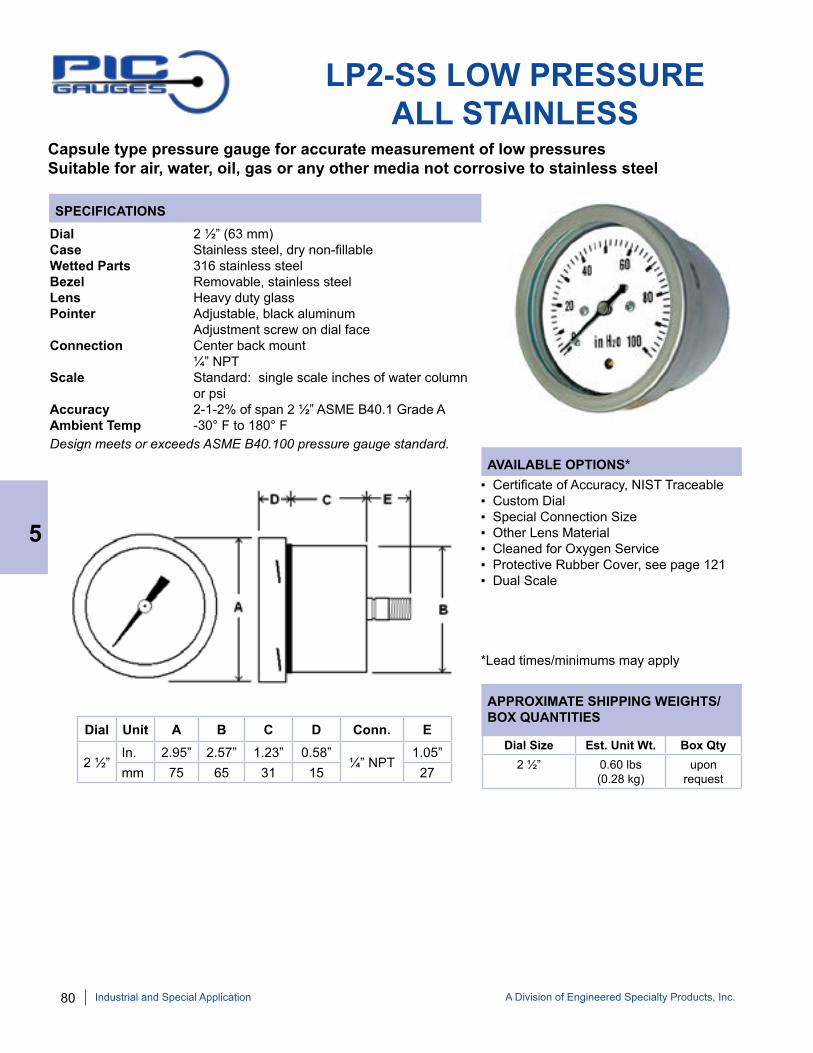
80 A Division of Engineered Specialty Products, Inc.
SPECIFICATIONS
AVAILABLE OPTIONS*
APPROXIMATE SHIPPING WEIGHTS/BOX QUANTITIES
LP2-SS LOW PRESSUREALL STAINLESS
Capsule type pressure gauge for accurate measurement of low pressuresSuitable for air, water, oil, gas or any other media not corrosive to stainless steel
Dial 2 ½” (63 mm)Case Stainless steel, dry non-fillableWetted Parts 316 stainless steelBezel Removable, stainless steelLens Heavy duty glassPointer Adjustable, black aluminum Adjustment screw on dial faceConnection Center back mount ¼” NPTScale Standard: single scale inches of water column or psiAccuracy 2-1-2% of span 2 ½” ASME B40.1 Grade AAmbient Temp -30° F to 180° F
▪ Certificate of Accuracy, NIST Traceable▪ Custom Dial▪ Special Connection Size▪ Other Lens Material▪ Cleaned for Oxygen Service▪ Protective Rubber Cover, see page 121▪ Dual Scale
*Lead times/minimums may apply
Dial Size Est. Unit Wt. Box Qty2 ½” 0.60 lbs
(0.28 kg)upon
request
5
Industrial and Special Application
Dial Unit A B C D Conn. E
2 ½” In. 2.95” 2.57” 1.23” 0.58”
¼” NPT1.05”
mm 75 65 31 15 27
Design meets or exceeds ASME B40.100 pressure gauge standard.

A Division of Engineered Specialty Products, Inc. 81
SPECIFICATIONS
AVAILABLE OPTIONS*
APPROXIMATE SHIPPING WEIGHTS/BOX QUANTITIES
LP3-SS LOW PRESSUREALL STAINLESS
Capsule type pressure gauge for accurate measurement of low pressuresSuitable for air, water, oil, gas or any other media not corrosive to stainless steel
Dial 2 ½” (63 mm)Case Stainless steel, dry non-fillableWetted Parts 316 stainless steelBezel Removable, stainless steelLens Heavy duty glassPointer Adjustable, black aluminum Adjustment screw on dial faceConnection Center back mount with u-clamp ¼” NPTScale Standard: single scale inches of water column or psiAccuracy 2-1-2% of span on 2 ½” ASME B40.1 Grade AAmbient Temp -30° F to 180° F
▪ Certificate of Accuracy, NIST Traceable ▪ Custom Dial▪ Special Connection Size▪ Other Lens Material▪ Cleaned for Oxygen Service▪ Dual Scale
*Lead times/minimums may apply
Dial Size Est. Unit Wt. Box Qty2 ½” 0.65 lbs
(0.30 kg)upon
request
Industrial and Special Application
5
Dial Unit A B C D Conn. E
2 ½” In. 2.95” 2.56” 1.33” 0.55”
¼” NPT1.10”
mm 75 65 34 14 28
Dial Unit F G H J
2 ½” In. 3.22” 2.83” 1.46” 1.46”mm 82 72 37 37
Design meets or exceeds ASME B40.100 pressure gauge standard.

82 A Division of Engineered Specialty Products, Inc.
SPECIFICATIONS
AVAILABLE OPTIONS*
APPROXIMATE SHIPPING WEIGHTS/BOX QUANTITIES
LP4-SS LOW PRESSURESTAINLESS STEEL CASE
Capsule type pressure gauge for accurate measurement of low pressuresSuitable for air, water, oil, gas or any other media not corrosive to stainless steel
Dial 2 ½” (63 mm)Case Stainless steel, dry non-fillableWetted Parts 316 stainless steelBezel Removable, stainless steelLens Heavy duty glassPointer Adjustable, black aluminum Adjustment screw on dial faceConnection Center back mount with front flange ¼” NPTScale Standard: single scale inches of water column or psiAccuracy 2-1-2% of span 2 ½” ASME B40.1 Grade AAmbient Temp -30° F to 180° F
▪ Certificate of Accuracy, NIST Traceable ▪ Custom Dial▪ Special Connection Size▪ Other Lens Material▪ Cleaned for Oxygen Service▪ Dual Scale
*Lead times/minimums may apply
Dial Size Est. Unit Wt. Box Qty2 ½” 0.65 lbs
(0.30 kg)upon
request
5
Industrial and Special Application
Dial Unit A B C D Conn. E F
2 ½” In. 2.95” 2.57” 1.23” 0.58”
¼” NPT1.05” 3.61”
mm 75 65 31 15 27 92
Design meets or exceeds ASME B40.100 pressure gauge standard.

A Division of Engineered Specialty Products, Inc. 83
SPECIFICATIONS
AVAILABLE OPTIONS*
APPROXIMATE SHIPPING WEIGHTS/BOX QUANTITIES
LP1-PS LOW PRESSUREPHENOLIC CASE
Capsule type pressure gauge for accurate measurement of low pressuresSuitable for air, water, oil, gas or any other media not corrosive to stainless steel
Dial 4 ½” (115 mm)Case Phenolic, dry non-fillableWetted Parts 316 stainless steelBezel PhenolicLens Tempered glassPointer Adjustable, black aluminum Adjustment screw on dial faceConnection Lower mount ½” or ¼” NPTScale Standard: single scale inches of water column or psiAccuracy 2-1-2% of span ASME B40.1 Grade AAmbient Temp -30° F to 180° F
▪ Certificate of Accuracy, NIST Traceable ▪ Custom Dial▪ Special Connection Size▪ Other Lens Material▪ Cleaned for Oxygen Service▪ Dual Scale
*Lead times/minimums may apply
Dial Size Est. Unit Wt. Box Qty4 ½” 2.10 lbs
(0.96 kg)upon
request
5
Dial Unit A B C D E F G NPT
4 ½” In. 5.10” 5.83” 3.23” 1.07” 1.65” 2.60” 1.41”
¼” or ½”mm 130 148 82 27 42 66 36
Industrial and Special Application
Design meets or exceeds ASME B40.100 pressure gauge standard.
Dial Range Figure Intervals
Graduation Intervals
200/0”wc Vac 20” wc 2” wc
100/0”wc Vac 10” wc 1” wc
30/0”wc Vac 5” wc 0.5” wc
Dial Range Figure Intervals
Graduation Intervals
0/15” wc 3” wc 0.2” wc
0/30” wc 5” wc 0.5” wc
0/60” wc 10” wc 0.5” wc
Dial Range Figure Intervals
Graduation Intervals
0/100” wc 20” wc 2” wc
0/200” wc 20” wc 2” wc
STANDARD DIAL CONFIGURATIONS FOR LP1-PS SERIES
Because of continuing improvements, increments and specifications are subject to change without notice. Consult PIC Gauges for availability.

84 A Division of Engineered Specialty Products, Inc.
SPECIFICATIONS
AVAILABLE OPTIONS*
APPROXIMATE SHIPPING WEIGHTS/BOX QUANTITIES
DIGITAL PRESSURE GAUGE
General purpose digital pressure gauge, backlit LED display for clear, concise readings
Dial 3” (76 mm)Case Black aluminum Display 4 digits standard Wetted Parts 304L & 316L stainless steelRanges Standard ranges from 30” hg vac to 5,000 psiConnection Lower mount ¼” NPT for 3”Measurement Units psi, BAR, MPaAccuracy 0.25% of span on 3” ASME B40.1 Grade 3AAmbient Temp 14° F to 140° FPower Supply 9 volt batteryFunctions Zero reset Backlight Peak/Hold
▪ Certificate of Accuracy, NIST Traceable▪ Protective Rubber Cover, see page 121▪ Special Connection Size
*Lead times/minimums may apply
Dial Size Est. Unit Weight
Box Qty
3” 1.10 lbs(0.50 kg)
upon request
Dial Unit A B C D E
3”In. 3.35” 2.03” 0.92” 4.21” ¼”
NPTmm 85 52 23 107
Dial Size Standard Part Numbers3” DPG-254L(RANGE CODE)
5
Industrial and Special Application
Stock RangesA = 30/0” Hg Vac L = 0/800 psi
E = 0/100 psi M = 0/1000 psiH = 0/300 psi P = 0/3000 psi
R = 0/5000 psi
Design meets or exceeds ASME B40.100 pressure gauge standard.
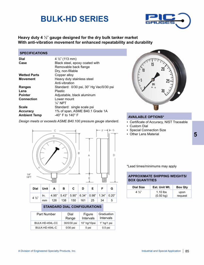
A Division of Engineered Specialty Products, Inc. 85
SPECIFICATIONS
AVAILABLE OPTIONS*
APPROXIMATE SHIPPING WEIGHTS/BOX QUANTITIES
BULK-HD SERIES
Heavy duty 4 ½” gauge designed for the dry bulk tanker market With anti-vibration movement for enhanced repeatability and durability
Dial 4 ½” (113 mm)Case Black steel, epoxy coated with Removable back flange Dry, non-fillableWetted Parts Copper alloyMovement Heavy duty stainless steel Anti-vibrationRanges Standard: 0/30 psi, 30” Hg Vac/0/30 psiLens PlasticPointer Adjustable, black aluminumConnection Lower mount ¼” NPTScale Standard: single scale psiAccuracy 1% of span, ASME B40.1 Grade 1AAmbient Temp -40° F to 140° F
▪ Certificate of Accuracy, NIST Traceable ▪ Custom Dial▪ Special Connection Size▪ Other Lens Material
*Lead times/minimums may apply
Dial Unit A B C D E F G
4 ½” In. 4.95” 5.43” 5.90” 6.34” 0.98” 1.34” 0.20” mm 126 138 150 161 25 34 5
Part Number Dial Range
Figure Intervals
Graduation Intervals
BULK-HD-454L-CC 30/0/30 psi 10” hg/10psi 1” hg/1 psi
BULK-HD-454L-C 0/30 psi 5 psi 0.5 psi
STANDARD DIAL CONFIGURATIONS
Dial Size Est. Unit Wt. Box Qty4 ½” 1.10 lbs
(0.50 kg)upon
request
Industrial and Special Application
5
Design meets or exceeds ASME B40.100 pressure gauge standard.

86 A Division of Engineered Specialty Products, Inc.
AVAILABLE OPTIONS*
APPROXIMATE SHIPPING WEIGHTS/BOX QUANTITIES
SPECIFICATIONS
S215L BACK FLANGE
Glycerine filled for added durability in applications where vibration or pulsation is presentStainless steel case and bezel, copper alloy internalsHeavy duty gauge designed for the dry bulk tanker market
Dial 4” (100 mm)Case Stainless steel with removable back flange Glycerine filledWetted Parts Copper alloyRanges Standard: 0/30 psiBezel Stainless steel, fixedLens PlasticPointer Black aluminumConnection Lower mount ¼” NPTScale Standard: single scale psiAccuracy 1% of span, ASME B40.1 Grade 1AAmbient Temp Glycerine Filled = 30° F to 160° F Dry = -30° F to 180° F
▪ Certificate of Accuracy, NIST Traceable▪ Custom Dial▪ Special Connection Size▪ Other Lens Material▪ Alternate Ranges
*Lead times/minimums may apply
Dial Unit A B C D E F
4” In. 5.13” 4.29” 1.77” 5.19” ¼”
NPT1.30”
mm 130 109 45 132 38
Dial Size Est. Unit Wt. Box Qty4” 1.65 lbs
(0.74 kg)30
Part Number Dial Range
Figure Intervals
Graduation Intervals
S215L-404C 0/30 psi 3 psi 0.2 psi
STANDARD DIAL CONFIGURATIONS
5
Industrial and Special Application
Design meets or exceeds ASME B40.100 pressure gauge standard.

A Division of Engineered Specialty Products, Inc. 87
500-UNO SERIES
“Use No Oil” gauge designed for use on compressed gas regulators and tankscopper alloy case, twist off lens, copper alloy internals
502D-UNO SERIES501D-UNO SERIES
NOTE: Because of continuing improvements, increments and specifications are subject to change.
Stock ranges vary by dial size and configuration. Consult PIC Gauges for availability.
Dial Range Figure Intervals
Graduation Intervals
0/30 psi 10 psi 1 psi
0/60 psi 10 psi 1 psi
0/100 psi 20 psi 2 psi
0/200 psi 40 psi 5 psi
0/300 psi 50 psi 5 psi
0/400 psi 50 psi 5 psi
0/600 psi 100 psi 20 psi
0/4000 psi 500 psi 100 psi
STANDARD DIAL CONFIGURATIONS FOR
500-UNO SERIES
Industrial and Special Application
5 SERIES TYPE
5 = Copper alloy Case, Copper alloy Internals
CONNECTION SIZE
4 = ¼” NPT
RANGE
C = 0/30 psi (Red zone 15-30 psi) D = 0/60 psi E = 0/100 psi G = 0/200 psi H = 0/300 psi I = 0/400 psi K = 0/600 psi Q = 0/4000 psi
SPECIAL FEATURES
0 = Standard Gauge
MOUNTING STYLE
1 = Lower Mount 2 = Center Back Mount
CASE FILLING
D = Dry
APPLICATION
UNO = “Use No Oil”
DIAL SIZE
20 = 2” Diameter 25 = 2 ½” Diameter
PART NUMBERING SYSTEM
EXAMPLE APPLICATIONS
WeldingBeverageCryogenic

88 A Division of Engineered Specialty Products, Inc.
SPECIFICATIONS
AVAILABLE OPTIONS*
APPROXIMATE SHIPPING WEIGHTS/BOX QUANTITIES
501D-UNO SERIES
“Use No Oil” gauge designed for use on compressed gas regulators and tankscopper alloy case, twist off lens, copper alloy internals
Dial 2” (50 mm), 2 ½” (63 mm)Case Highly polished copper alloy, dry non-fillableWetted Parts Copper alloyBezel Removable lensLens Plastic, twist on Pointer Black aluminumConnection Lower mount ¼” NPTScale Standard: single scale psiAccuracy 3-2-3% of span, ASME B40.1 Grade BAmbient Temp -4° F to 140° F
▪ Custom Dial▪ Special Connection Size▪ Cleaned for Oxygen Service▪ Listed (UL 252A or UL 404)▪ Alternate Case Material - Painted Steel - Plastic - Stainless Steel
*Lead times/minimums may apply
Dial Unit A B C D E
2”In. 2.31” 1.2” 2.07” 1.13” ¼”
NPTmm 59 31 53 29
2 ½” In. 2.83” 1.13” 2.65” 1.13” ¼”
NPTmm 72 29 68 29
Dial Size Est. Unit Wt. Box Qty2” 0.30 lbs
(0.12 kg)upon
request2 ½” 0.35 lbs
(0.16 kg)upon
request
5
Industrial and Special Application
Design meets or exceeds ASME B40.100 pressure gauge standard.
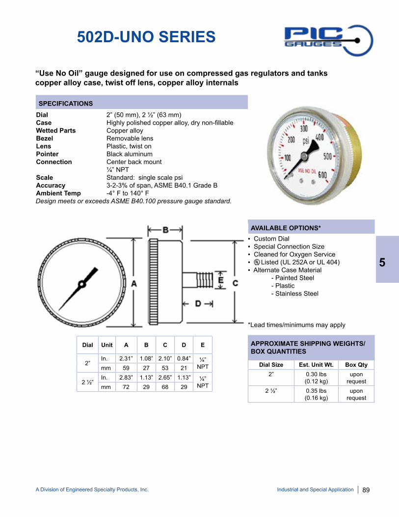
A Division of Engineered Specialty Products, Inc. 89
SPECIFICATIONS
AVAILABLE OPTIONS*
APPROXIMATE SHIPPING WEIGHTS/BOX QUANTITIES
502D-UNO SERIES
“Use No Oil” gauge designed for use on compressed gas regulators and tankscopper alloy case, twist off lens, copper alloy internals
Dial 2” (50 mm), 2 ½” (63 mm)Case Highly polished copper alloy, dry non-fillableWetted Parts Copper alloyBezel Removable lensLens Plastic, twist onPointer Black aluminum Connection Center back mount ¼” NPTScale Standard: single scale psiAccuracy 3-2-3% of span, ASME B40.1 Grade BAmbient Temp -4° F to 140° F
▪ Custom Dial▪ Special Connection Size▪ Cleaned for Oxygen Service▪ Listed (UL 252A or UL 404)▪ Alternate Case Material - Painted Steel - Plastic - Stainless Steel
*Lead times/minimums may apply
Dial Unit A B C D E
2”In. 2.31” 1.08” 2.10” 0.84” ¼”
NPTmm 59 27 53 21
2 ½” In. 2.83” 1.13” 2.65” 1.13” ¼”
NPTmm 72 29 68 29
Dial Size Est. Unit Wt. Box Qty2” 0.30 lbs
(0.12 kg)upon
request2 ½” 0.35 lbs
(0.16 kg)upon
request
Industrial and Special Application
5
Design meets or exceeds ASME B40.100 pressure gauge standard.
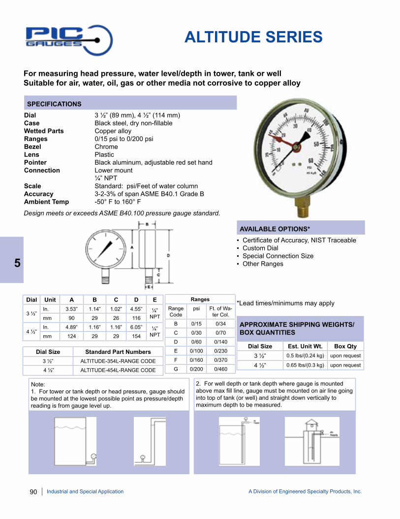
90 A Division of Engineered Specialty Products, Inc.
SPECIFICATIONS
AVAILABLE OPTIONS*
APPROXIMATE SHIPPING WEIGHTS/BOX QUANTITIES
ALTITUDE SERIES
For measuring head pressure, water level/depth in tower, tank or well Suitable for air, water, oil, gas or other media not corrosive to copper alloy
Dial 3 ½” (89 mm), 4 ½” (114 mm)Case Black steel, dry non-fillableWetted Parts Copper alloyRanges 0/15 psi to 0/200 psiBezel ChromeLens PlasticPointer Black aluminum, adjustable red set handConnection Lower mount ¼” NPTScale Standard: psi/Feet of water columnAccuracy 3-2-3% of span ASME B40.1 Grade BAmbient Temp -50° F to 160° F
▪ Certificate of Accuracy, NIST Traceable ▪ Custom Dial▪ Special Connection Size▪ Other Ranges
*Lead times/minimums may apply
Note: 1. For tower or tank depth or head pressure, gauge should be mounted at the lowest possible point as pressure/depth reading is from gauge level up.
2. For well depth or tank depth where gauge is mounted above max fill line, gauge must be mounted on air line going into top of tank (or well) and straight down vertically to maximum depth to be measured.
Dial Size Est. Unit Wt. Box Qty3 ½” 0.5 lbs/(0.24 kg) upon request
4 ½” 0.65 lbs/(0.3 kg) upon request
5
Industrial and Special Application
Design meets or exceeds ASME B40.100 pressure gauge standard.
Dial Unit A B C D E
3 ½” In. 3.53” 1.14” 1.02” 4.55” ¼”
NPTmm 90 29 26 116
4 ½” In. 4.89” 1.16” 1.16” 6.05” ¼”
NPTmm 124 29 29 154
Dial Size Standard Part Numbers3 ½” ALTITUDE-354L-RANGE CODE
4 ½” ALTITUDE-454L-RANGE CODE
RangesRange Code
psi Ft. of Wa-ter Col.
B 0/15 0/34
C 0/30 0/70
D 0/60 0/140
E 0/100 0/230
F 0/160 0/370
G 0/200 0/460

A Division of Engineered Specialty Products, Inc. 91
AMMONIA REFRIGERATION GAUGES
For ammonia refrigeration applications, PIC Gauges ammonia gauges measure ammonia refrigerant pressure and corresponding temperature.
AMMONIA-LF SERIES401NH3 SERIES
NOTE: Because of continuing improvements, increments and specifications are subject to change. Stock ranges vary by dial size and configuration. Consult PIC Gauges for availability.
Part Number
Dial Range Figure Intervals
Graduation Intervals
401NH3-254CF 30/0/150 30” hg/25 psi 5” hg/5 psi
401NH3-254CH 30/0/300 30” hg/50 psi 5” hg/5 psi
401NH3-404CF 30/0/150 30” hg/25 psi 5” hg/5 psi
401NH3-404CH 30/0/300 30” hg/50 psi 5” hg/5 psi
AMMONIA-LF-254CF 30/0/150 30” hg/20 psi 5” hg/2 psi
AMMONIA-LF-254CH 30/0/300 30” hg/50 psi 10” hg/5 psi
AMMONIA-LF-404CF 30/0/150 30” hg/25 psi 5” hg/5 psi
AMMONIA-LF-404CH 30/0/300 30” hg/50 psi 5” hg/5 psi
STANDARD DIAL CONFIGURATIONS FOR AMMONIA SERIES
*For Agricultural Ammonia gauges, see page 91.
Industrial and Special Application
5

92 A Division of Engineered Specialty Products, Inc.
SPECIFICATIONS
AVAILABLE OPTIONS*
APPROXIMATE SHIPPING WEIGHTS/BOX QUANTITIES
401NH3 SERIES
Dry non-fillable gauge for ammonia refrigeration applicationsChrome plated steel case, stainless steel internals and steel socket
Dial 2 ½” (63 mm), 4” (100 mm)Case Chrome plated steel case, dry non-fillableWetted Parts Steel socket, stainless steel Bourdon tubeRanges 30/0/150 psi/-40/0/80° F 30/0/300 psi/-40/0/120° FBezel Removable lensLens Plastic, twist-offPointer 2 ½” - adjustable, black aluminum 4” - without adjustment, black aluminum Connection Lower mount ¼” NPTScale Standard: psi/° F temperature equivalentAccuracy 3-2-3% of span ASME B40.1 Grade BAmbient Temp Dry = -40° F to 180° F
▪ Custom Dial▪ Special Connection Size▪ Other Ranges
*Lead times/minimums may apply
Dial Unit A B C D E
2 ½” In. 2.87” 1.14” 2.65” 0.84” ¼”
NPTmm 73 29 67 21
4” In. 4.21” 1.35” 3.89” 1.03” ¼”
NPTmm 107 34 99 26
Dial Size Est. Unit Wt. Box Qty2 ½” 0.3 lbs
(0.14 kg)50
4” 0.55 lbs(0.24 kg)
50
5
Industrial and Special Application
Design meets or exceeds ASME B40.100 pressure gauge standard.

A Division of Engineered Specialty Products, Inc. 93
SPECIFICATIONS
AVAILABLE OPTIONS*
APPROXIMATE SHIPPING WEIGHTS/BOX QUANTITIES
AMMONIA-LF SERIES
Glycerine filled gauge for ammonia refrigeration applicationsStainless steel case, 316 stainless steel internals
Dial 2 ½” (63 mm), 4” (100 mm)Case Stainless steel, glycerine filledWetted Parts 316 stainless steelRanges 30/0/150 psi/-40/0/80° F 30/0/300 psi/-40/0/120° FBezel Removable, stainless steelLens PolycarbonatePointer Adjustable, black aluminum Connection Lower mount ¼” NPTScale Standard: psi/° F temperature equivalentAccuracy 2-1-2% of span ASME B40.1 Grade AAmbient Temp Glycerine Filled = 30° F to 160° F Dry = -40° F to 180° F
▪ Custom Dial▪ Liquid Fill Options, see page 176▪ Glow Dials▪ Special Connection Size▪ Other Ranges
*Lead times/minimums may apply
Dial Unit A B C D E F G H I
2 ½” In. 2.72” 0.76” 2.50” 0.24” 0.49” 0.44” 0.70” 0.55” ¼”
NPTmm 69 19.5 64 6.2 12.4 11.3 18 14
4” In. 4.32” 1.30” 4.06” 0.52” 0.58” 0.57” 1.08” 0.84” ¼”
NPTmm 110 33 103 13.3 15 14.6 27.5 21.5
Dial Size Est. Unit Wt. Box Qty2 ½” 0.50 lbs
(0.22 kg)100
4” 1.75 lbs(0.80 kg)
30
Industrial and Special Application
5
Design meets or exceeds ASME B40.100 pressure gauge standard.
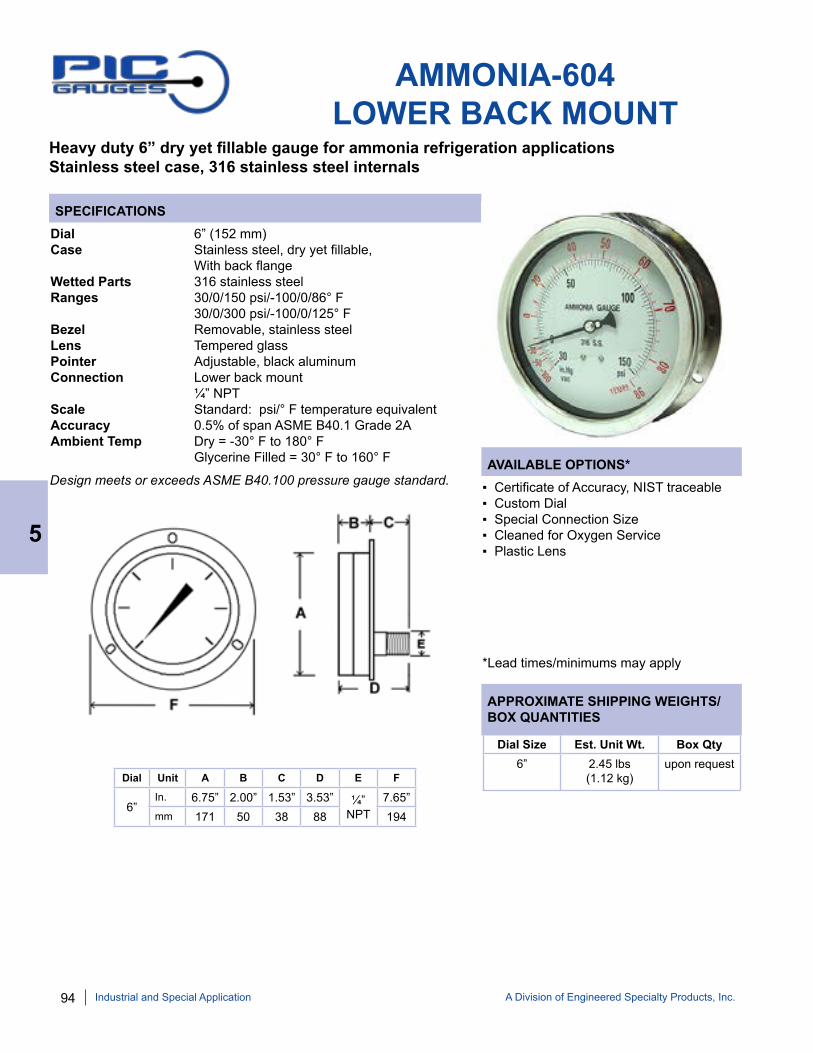
94 A Division of Engineered Specialty Products, Inc.
SPECIFICATIONS
AVAILABLE OPTIONS*
APPROXIMATE SHIPPING WEIGHTS/BOX QUANTITIES
AMMONIA-604LOWER BACK MOUNT
Heavy duty 6” dry yet fillable gauge for ammonia refrigeration applicationsStainless steel case, 316 stainless steel internals
Dial 6” (152 mm)Case Stainless steel, dry yet fillable, With back flangeWetted Parts 316 stainless steelRanges 30/0/150 psi/-100/0/86° F 30/0/300 psi/-100/0/125° F Bezel Removable, stainless steel Lens Tempered glassPointer Adjustable, black aluminumConnection Lower back mount ¼” NPTScale Standard: psi/° F temperature equivalentAccuracy 0.5% of span ASME B40.1 Grade 2AAmbient Temp Dry = -30° F to 180° F Glycerine Filled = 30° F to 160° F
▪ Certificate of Accuracy, NIST traceable ▪ Custom Dial▪ Special Connection Size▪ Cleaned for Oxygen Service▪ Plastic Lens
*Lead times/minimums may apply
Dial Unit A B C D E F
6”In. 6.75” 2.00” 1.53” 3.53” ¼”
NPT7.65”
mm 171 50 38 88 194
Dial Size Est. Unit Wt. Box Qty6” 2.45 lbs
(1.12 kg)upon request
Design meets or exceeds ASME B40.100 pressure gauge standard.
5
Industrial and Special Application

A Division of Engineered Specialty Products, Inc. 95
SPECIFICATIONS
AVAILABLE OPTIONS*
APPROXIMATE SHIPPING WEIGHTS/BOX QUANTITIES
AMMONIA-804LOWER BACK MOUNT
Heavy duty black aluminum gaugeRemovable bezel, adjustable pointerSuitable for applications not corrosive to stainless steel
Dial 8” (203 mm)Case Aluminum black painted, dry non-fillable, rear flangeWetted Parts 316 stainless steelRanges 30/0/150 psi/-100/0/84° F 30/0/300 psi/-100/0/125° F Bezel Removable, black aluminum Lens Tempered glassPointer Adjustable, black aluminumConnection Lower back mount ¼” NPTScale Standard: psi/° F temperature equivalentAccuracy 1% of span ASME B40.1 Grade 1AAmbient Temp -30° F to 180° F
▪ Certificate of Accuracy, NIST traceable ▪ Custom Dial▪ Special Connection Size▪ Cleaned for Oxygen Service▪ Plastic Lens
*Lead times/minimums may apply
Dial Unit A B C D E F
8”In. 7.93” 1.59” 1.41” 3.00” ¼”
NPT9.13”
mm 201 40 36 76 232
Dial Size Est. Unit Wt. Box Qty8” 3.95 lbs
(1.80 kg)upon request
Industrial and Special Application
5

96 A Division of Engineered Specialty Products, Inc.
AMMONIA PROCESS GAUGE SPECIFICATIONS
ADDITIONAL AMMONIA GAUGES
Ammonia refrigerant gauges
AMMONIA PANEL MOUNT SPECIFICATIONS
Dial 4 ½” (114 mm), 6” (160 mm) Case Phenolic - Solid front blow out back on 4 ½” Aluminum with hinged front flange on 4 ½” & 6” Wetted Parts 316 stainless steel Ranges 30/0/150 psi/-40/0/80° F 30/0/300 psi/-40/0/120° F Bezel Removable Lens Polycarbonate Pointer Adjustable, black aluminum Connection Lower mount or lower back mount ¼” or ½” NPT for 4 ½” & 6” Scale Standard: psi/° F temperature equivalent Accuracy 0.5% of span on 4 ½” & 6” ASME B40.1 Grade 2A Ambient Temp Glycerine Filled = 30° F to 160° F Dry = -30° F to 180° F
Dial 2 ½” (63 mm), 4” (100 mm), 6” (160 mm) Case Stainless steel Wetted Parts 316 stainless steel Ranges 30/0/150 psi/-40/0/80° F 30/0/300 psi/-40/0/120° F Bezel Stainless steel, removable Lens Laminated safety glass Pointer Adjustable, black aluminum Connection Lower back mount with front flange ¼” NPT for 2 ½” ¼” or ½” NPT for 4” & 6” Scale Standard: psi/° F temperature equivalent Accuracy 1% of span ASME B40.1 Grade 1A Ambient Temp Glycerine Filled = 30° F to 160° F Dry = -30° F to 180° F
4501 4502 4504 6504page 58 - page 60
314D-254/404/6004page 42 & page 55
5
Industrial and Special Application
Design meets or exceeds ASME B40.100 pressure gauge standard.
Design meets or exceeds ASME B40.100 pressure gauge standard.
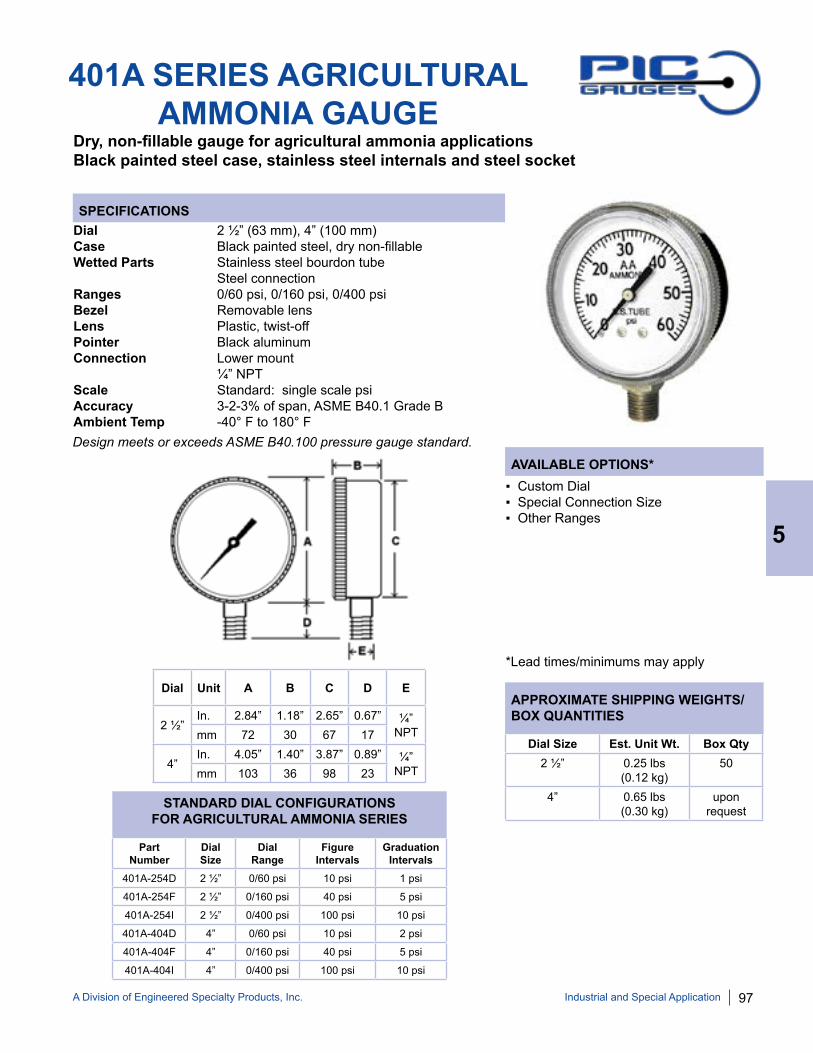
A Division of Engineered Specialty Products, Inc. 97
SPECIFICATIONS
AVAILABLE OPTIONS*
APPROXIMATE SHIPPING WEIGHTS/BOX QUANTITIES
401A SERIES AGRICULTURALAMMONIA GAUGE
Dry, non-fillable gauge for agricultural ammonia applicationsBlack painted steel case, stainless steel internals and steel socket
Dial 2 ½” (63 mm), 4” (100 mm)Case Black painted steel, dry non-fillableWetted Parts Stainless steel bourdon tube Steel connectionRanges 0/60 psi, 0/160 psi, 0/400 psiBezel Removable lensLens Plastic, twist-offPointer Black aluminum Connection Lower mount ¼” NPTScale Standard: single scale psiAccuracy 3-2-3% of span, ASME B40.1 Grade BAmbient Temp -40° F to 180° F
▪ Custom Dial▪ Special Connection Size▪ Other Ranges
*Lead times/minimums may apply
Dial Unit A B C D E
2 ½” In. 2.84” 1.18” 2.65” 0.67” ¼”
NPTmm 72 30 67 17
4” In. 4.05” 1.40” 3.87” 0.89” ¼”
NPTmm 103 36 98 23
Dial Size Est. Unit Wt. Box Qty2 ½” 0.25 lbs
(0.12 kg)50
4” 0.65 lbs(0.30 kg)
uponrequest
Industrial and Special Application
5
Design meets or exceeds ASME B40.100 pressure gauge standard.
Part Number
Dial Size
Dial Range
Figure Intervals
Graduation Intervals
401A-254D 2 ½” 0/60 psi 10 psi 1 psi
401A-254F 2 ½” 0/160 psi 40 psi 5 psi
401A-254I 2 ½” 0/400 psi 100 psi 10 psi
401A-404D 4” 0/60 psi 10 psi 2 psi
401A-404F 4” 0/160 psi 40 psi 5 psi
401A-404I 4” 0/400 psi 100 psi 10 psi
STANDARD DIAL CONFIGURATIONS FOR AGRICULTURAL AMMONIA SERIES

98 A Division of Engineered Specialty Products, Inc.
SPECIFICATIONS
AVAILABLE OPTIONS*
APPROXIMATE SHIPPING WEIGHTS/BOX QUANTITIES
RECTANGLE (EDGE) GAUGE
Compact rectangle/edge gauge, plastic case, copper alloy wetted partsSuitable for air, water, oil, gas or other media not corrosive to copper alloy
Dial 1 ¾” x ½” horizontal or verticalCase Plastic, with or without mounting bracketWetted Parts Copper alloyRanges 0/60 psi, 0/100 psi, 0/120 psiLens PlasticPointer Red plasticConnection Back mount 10/32” female thread or 1/32” hose barb connectionScale Standard: psi/kg/cm2
Accuracy 5% of span on ASME B40.1 Grade DAmbient Temp Dry = -50° F to 160° F
▪ Single Scale psi▪ Special Connection Size▪ Other Ranges▪ Other Mounting Options/Styles - Front Bracket - Rear Bracket - Panel Flange - Panel Clip
*Lead times/minimums may apply
Part Number Range Connection BracketRECT-60FB 0/60 psi 10/32 back FrontRECT-60NB 0/60 psi 10/32 back NoneRECT-100FB 0/100 psi 10/32 back FrontRECT-120FB 0/120 psi 10/32 back Front
STANDARD CONFIGURATIONS
Size Est. Unit Wt. Box Qty1 ¾” 0.10 lbs
(0.04 kg)upon
request
5
Industrial and Special Application
Dial Unit A B C D E F G
1 ¾” In. 1.76" 2.28” 0.51” 0.43” 0.55” 2.5” 2.16”mm 45 58 13 11 14 63.6 55
Shown with optional panel mount front bracket
Design meets or exceeds ASME B40.100 pressure gauge standard.

A Division of Engineered Specialty Products, Inc. 99
SPECIFICATIONS
AVAILABLE OPTIONS*
APPROXIMATE SHIPPING WEIGHTS/BOX QUANTITIES
GT SERIESGAS TEST GAUGE
▪ Custom Dial▪ Special Connection Size▪ Other Ranges
*Lead times/minimums may apply
HORIZONTAL 2” DIAL SIZE 1/2” FNPT: 0.65 lbs (0.28 kg)/50 pcs 3/4” FNPT: 0.65 lbs (0.30 kg)/50 pcs 1” FNPT: 0.85 lbs (0.38 kg)/50 pcs
VERTICAL 2” DIAL SIZE 1/2” FNPT: 0.70 lbs (0.32 kg)/50 pcs 3/4” FNPT: 0.65 lbs (0.28 kg)/50 pcs 1” FNPT: 0.85 lbs (0.38 kg)/50 pcs
BELL 2” DIAL SIZE 1/2” FNPT: 0.40 lbs (0.20 kg)/50 pcs 3/4” FNPT: 0.50 lbs (0.22 kg)/50 pcs 1” FNPT: 0.60 lbs (0.26 kg)/50 pcs
SERIES TYPE GT = Gas Test Gauge 2” Dial, Black Steel Case, Copper alloy Internals
CONNECTION SIZE
1 = 1” FNPT ¾ = ¾” FNPT ½ = ½” FNPT
RANGE
15 = 0/15 psi 30 = 0/30 psi 60 = 0/60 psi 100 = 0/100 psi 160 = 0/160 psi 200 = 0/200 psi
HOUSING
H = Horizontal V = Vertical BELL = Bell
PART NUMBERING SYSTEM
Dial Range Figure Intervals
Graduation Intervals
0/15 psi 1 psi 0.1 psi
0/30 psi 5 psi 0.25 psi
0/60 psi 10 psi 0.5 psi
0/100 psi 20 psi 1 psi
0/160 psi 20 psi 2 psi
0/200 psi 20 psi 5 psi
STANDARD DIAL CONFIGURATIONS FOR
GAS TEST SERIES
Industrial and Special Application
5
Utility gas test gauge with horizontal, vertical or bell shaped housing For pressure tests of residential and commercial piping systems
Dial 2” (50 mm)Case Black painted steel, dry non-fillableWetted Parts Copper alloy Bourdon tube & socket Steel block (Horizontal/vertical chrome plated steel)Ranges Standard ranges: 0/15 psi to 0/200 psiBezel PlasticLens Plastic, snap in Pointer Black aluminum Connection Lower mount ½”, ¾” or 1” FNPTScale Standard: single scale psiAccuracy 3-2-3% of span, ASME B40.1 Grade BAmbient Temp -40° F to 160° F Test Block Steel with valve for pressurizationDesign meets or exceeds ASME B40.100 pressure gauge standard.
NOTE: Not all part numbers or options are available from stock. Consult PIC Gauges for availability.
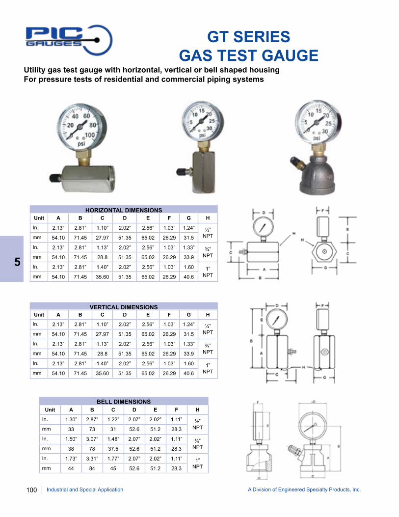
100 A Division of Engineered Specialty Products, Inc.
GT SERIESGAS TEST GAUGE
Unit A B C D E F G H
In. 2.13” 2.81” 1.10” 2.02” 2.56” 1.03” 1.24” ½” NPTmm 54.10 71.45 27.97 51.35 65.02 26.29 31.5
In. 2.13” 2.81” 1.13” 2.02” 2.56” 1.03” 1.33” ¾”NPTmm 54.10 71.45 28.8 51.35 65.02 26.29 33.9
In. 2.13” 2.81” 1.40” 2.02” 2.56” 1.03” 1.60 1” NPTmm 54.10 71.45 35.60 51.35 65.02 26.29 40.6
HORIZONTAL DIMENSIONS
Unit A B C D E F G H
In. 2.13” 2.81” 1.10” 2.02” 2.56” 1.03” 1.24” ½” NPTmm 54.10 71.45 27.97 51.35 65.02 26.29 31.5
In. 2.13” 2.81” 1.13” 2.02” 2.56” 1.03” 1.33” ¾”NPTmm 54.10 71.45 28.8 51.35 65.02 26.29 33.9
In. 2.13” 2.81” 1.40” 2.02” 2.56” 1.03” 1.60 1” NPTmm 54.10 71.45 35.60 51.35 65.02 26.29 40.6
VERTICAL DIMENSIONS
Unit A B C D E F H
In. 1.30” 2.87” 1.22” 2.07” 2.02” 1.11” ½” NPTmm 33 73 31 52.6 51.2 28.3
In. 1.50” 3.07” 1.48” 2.07” 2.02” 1.11” ¾”NPTmm 38 78 37.5 52.6 51.2 28.3
In. 1.73” 3.31” 1.77” 2.07” 2.02” 1.11” 1” NPTmm 44 84 45 52.6 51.2 28.3
BELL DIMENSIONS
5
Industrial and Special Application
Utility gas test gauge with horizontal, vertical or bell shaped housing For pressure tests of residential and commercial piping systems
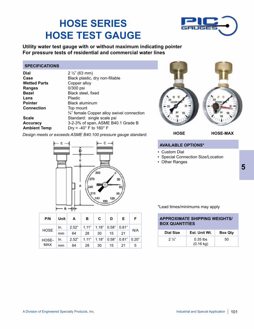
A Division of Engineered Specialty Products, Inc. 101
SPECIFICATIONS
AVAILABLE OPTIONS*
APPROXIMATE SHIPPING WEIGHTS/BOX QUANTITIES
HOSE SERIESHOSE TEST GAUGE
Utility water test gauge with or without maximum indicating pointerFor pressure tests of residential and commercial water lines
Dial 2 ½” (63 mm)Case Black plastic, dry non-fillableWetted Parts Copper alloyRanges 0/300 psi Bezel Black steel, fixedLens PlasticPointer Black aluminum Connection Top mount ¾” female Copper alloy swivel connection Scale Standard: single scale psiAccuracy 3-2-3% of span, ASME B40.1 Grade BAmbient Temp Dry = -40° F to 160° F
▪ Custom Dial▪ Special Connection Size/Location▪ Other Ranges
*Lead times/minimums may apply
HOSE HOSE-MAX
Dial Size Est. Unit Wt. Box Qty
2 ½” 0.35 lbs (0.16 kg)
50
Industrial and Special Application
5
P/N Unit A B C D E F
HOSEIn. 2.52” 1.11” 1.18” 0.58” 0.81”
N/Amm 64 28 30 15 21
HOSE-MAX
In. 2.52” 1.11” 1.18” 0.58” 0.81” 0.20”mm 64 28 30 15 21 5
Design meets or exceeds ASME B40.100 pressure gauge standard.

102 A Division of Engineered Specialty Products, Inc.
SPECIFICATIONS
AVAILABLE OPTIONS*
APPROXIMATE SHIPPING WEIGHTS/BOX QUANTITIES
509L LONG WALL MINING GAUGE
One-piece forged Copper alloy gauge designed for long wall mining equipment0/9000 psi color zone dial and hydraulic quick connect
Dial 2” (50 mm), color zones Red: 0/4000 psi Green: 4000/6000 psi Yellow: 6000/9000 psiCase Forged Copper alloy, silicone filledWetted Parts Copper alloyRanges 0/9000 psi / 0/600 BARBezel Stainless steelLens PlasticPointer White aluminumConnection Lower mount 3/8” “Steck-o” type mining industry standard Hydraulic quick connect with Buna N® o-ring & nylon washer, with M3 restrictor screwScale Standard: psi/BARAccuracy 2-1-2% of span, ASME B40.1 Grade AAmbient Temp Silicone Filled = -30° F to 160° F ▪ Custom Dial
▪ Special Connection Size▪ Other Ranges
*Lead times/minimums may apply
Dial Unit A B C D E F
2” In. 2.10” 1.96” 0.44” 1.13” 0.79” 0.55”mm 53 50 11 29 20 14
Dial Unit G H I J K L
2” In. 0.30” 0.20” 0.19” 0.19” 0.13” 0.13”mm 8 5 5 5 3 3
Dial Size Est. Unit Wt. Box Qty
2” 0.60 lbs (0.26 kg)
50
5
Industrial and Special Application
Design meets or exceeds ASME B40.100 pressure gauge standard.

A Division of Engineered Specialty Products, Inc. 103
SPECIFICATIONS
AVAILABLE OPTIONS*
APPROXIMATE SHIPPING WEIGHTS/BOX QUANTITIES
1” MINI BOURDON TUBE GAUGE
Miniature gauge for applications where space constraints are a concernSuitable for air, water, oil, gas or other media not corrosive to Copper alloy
Dial 1” (25.4 mm)Case Black plastic, dry non-fillableWetted Parts Copper alloyRanges 0/30, 0/60, 0/100, 0/160 psi Lens PlasticPointer Black aluminum Connection Center back mount ⅛” NPT with 10/32” tapScale Standard: single scale psiAccuracy 3-2-3% of span, 1” ASME B40.1 Grade BAmbient Temp Dry = -30° F to 180° F
▪ Custom Dial▪ Special Connection Size▪ Other Ranges▪ Built-in Snubber
*Lead times/minimums may apply
Dial Unit A B C1 C2 D E F
1”In. 0.98” 0.58” 0.34” 0.28” 1.21” ⅛”
NPT0.47”
mm 25 15 9 7 31 12
Part Number Range102D-108C 0/30 psi
102D-108D 0/60 psi
102D-108E 0/100 psi
102D-108F 0/160 psi
102D-108G 0/200 psi
102D-108H 0/300 psi
STANDARD PART NUMBERS
Dial Size Est. Unit Wt. Box Qty
1” 0.05 lbs (0.02 kg)
uponrequest
Industrial and Special Application
5
Design meets or exceeds ASME B40.100 pressure gauge standard.
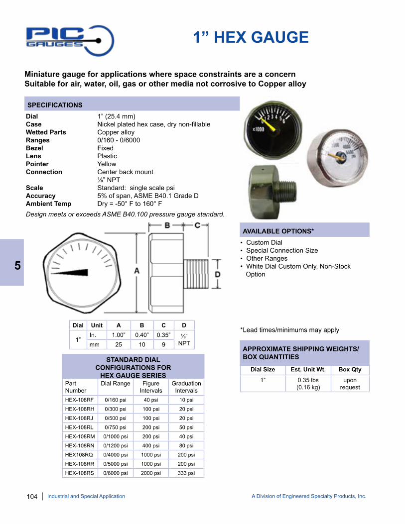
104 A Division of Engineered Specialty Products, Inc.
SPECIFICATIONS
AVAILABLE OPTIONS*
APPROXIMATE SHIPPING WEIGHTS/BOX QUANTITIES
1” HEX GAUGE
Miniature gauge for applications where space constraints are a concernSuitable for air, water, oil, gas or other media not corrosive to Copper alloy
Dial 1” (25.4 mm)Case Nickel plated hex case, dry non-fillableWetted Parts Copper alloyRanges 0/160 - 0/6000Bezel FixedLens PlasticPointer YellowConnection Center back mount ⅛” NPTScale Standard: single scale psiAccuracy 5% of span, ASME B40.1 Grade DAmbient Temp Dry = -50° F to 160° F
▪ Custom Dial▪ Special Connection Size▪ Other Ranges• White Dial Custom Only, Non-Stock Option
*Lead times/minimums may applyDial Unit A B C D
1” In. 1.00” 0.40” 0.35” ⅛”
NPTmm 25 10 9
Part Number
Dial Range Figure Intervals
Graduation Intervals
HEX-108RF 0/160 psi 40 psi 10 psi
HEX-108RH 0/300 psi 100 psi 20 psi
HEX-108RJ 0/500 psi 100 psi 20 psi
HEX-108RL 0/750 psi 200 psi 50 psi
HEX-108RM 0/1000 psi 200 psi 40 psi
HEX-108RN 0/1200 psi 400 psi 80 psi
HEX108RQ 0/4000 psi 1000 psi 200 psi
HEX-108RR 0/5000 psi 1000 psi 200 psi
HEX-108RS 0/6000 psi 2000 psi 333 psi
STANDARD DIAL CONFIGURATIONS FOR
HEX GAUGE SERIESDial Size Est. Unit Wt. Box Qty
1” 0.35 lbs (0.16 kg)
uponrequest
5
Industrial and Special Application
Design meets or exceeds ASME B40.100 pressure gauge standard.
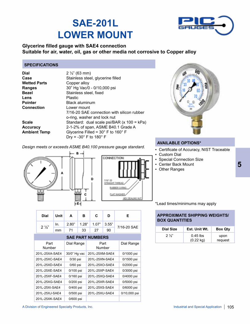
A Division of Engineered Specialty Products, Inc. 105
SPECIFICATIONS
AVAILABLE OPTIONS*
APPROXIMATE SHIPPING WEIGHTS/BOX QUANTITIES
SAE-201LLOWER MOUNT
Glycerine filled gauge with SAE4 connectionSuitable for air, water, oil, gas or other media not corrosive to Copper alloy
Dial 2 ½” (63 mm)Case Stainless steel, glycerine filledWetted Parts Copper alloyRanges 30” Hg Vac/0 - 0/10,000 psi Bezel Stainless steel, fixed Lens PlasticPointer Black aluminum Connection Lower mount 7/16-20 SAE connection with silicon rubber o-ring, washer and lock nutScale Standard: dual scale psi/BAR (x 100 = kPa)Accuracy 2-1-2% of span, ASME B40.1 Grade AAmbient Temp Glycerine Filled = 30° F to 160° F Dry = -30° F to 180° F
▪ Certificate of Accuracy, NIST Traceable▪ Custom Dial▪ Special Connection Size▪ Center Back Mount▪ Other Ranges
*Lead times/minimums may apply
Dial Unit A B C D E
2 ½”In. 2.80” 1.28” 1.07” 3.55”
7/16-20 SAEmm 71 33 27 90
Part Number
Dial Range Part Number
Dial Range
201L-25XA-SAE4 30/0” Hg vac 201L-25XM-SAE4 0/1000 psi
201L-25XC-SAE4 0/30 psi 201L-25XN-SAE4 0/1500 psi
201L-25XD-SAE4 0/60 psi 201L-25XO-SAE4 0/2000 psi
201L-25XE-SAE4 0/100 psi 201L-25XP-SAE4 0/3000 psi
201L-25XF-SAE4 0/160 psi 201L-25XQ-SAE4 0/4000 psi
201L-25XG-SAE4 0/200 psi 201L-25XR-SAE4 0/5000 psi
201L-25XI-SAE4 0/400 psi 201L-25XS-SAE4 0/6000 psi
201L-25XJ-SAE4 0/500 psi 201L-25XU-SAE4 0/10,000 psi
201L-25XK-SAE4 0/600 psi
SAE PART NUMBERS
Dial Size Est. Unit Wt. Box Qty
2 ½” 0.45 lbs (0.22 kg)
uponrequest
Industrial and Special Application
5
Design meets or exceeds ASME B40.100 pressure gauge standard.
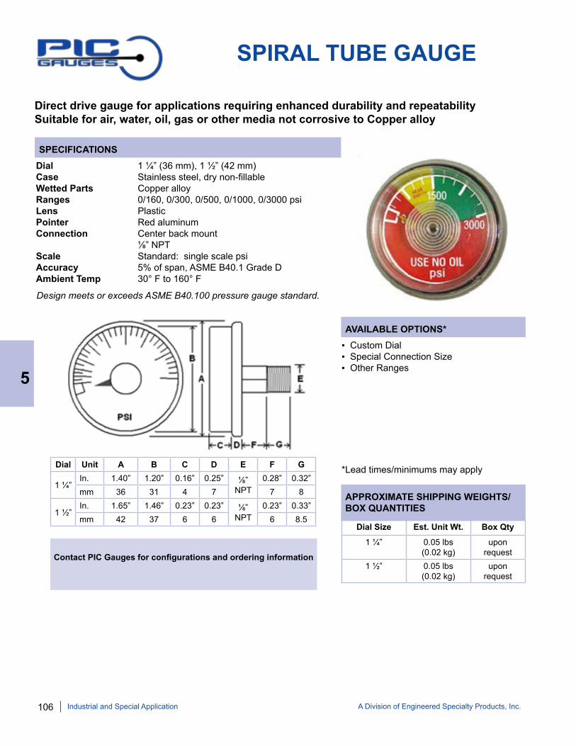
106 A Division of Engineered Specialty Products, Inc.
SPECIFICATIONS
AVAILABLE OPTIONS*
APPROXIMATE SHIPPING WEIGHTS/BOX QUANTITIES
SPIRAL TUBE GAUGE
Direct drive gauge for applications requiring enhanced durability and repeatabilitySuitable for air, water, oil, gas or other media not corrosive to Copper alloy
Dial 1 ¼” (36 mm), 1 ½” (42 mm)Case Stainless steel, dry non-fillableWetted Parts Copper alloyRanges 0/160, 0/300, 0/500, 0/1000, 0/3000 psiLens PlasticPointer Red aluminumConnection Center back mount ⅛” NPTScale Standard: single scale psiAccuracy 5% of span, ASME B40.1 Grade DAmbient Temp 30° F to 160° F
▪ Custom Dial▪ Special Connection Size▪ Other Ranges
*Lead times/minimums may applyDial Unit A B C D E F G
1 ¼” In. 1.40” 1.20” 0.16” 0.25” ⅛”
NPT0.28” 0.32”
mm 36 31 4 7 7 8
1 ½” In. 1.65” 1.46” 0.23” 0.23” ⅛”
NPT0.23” 0.33”
mm 42 37 6 6 6 8.5
Contact PIC Gauges for configurations and ordering information
Dial Size Est. Unit Wt. Box Qty
1 ¼” 0.05 lbs (0.02 kg)
uponrequest
1 ½” 0.05 lbs (0.02 kg)
uponrequest
5
Industrial and Special Application
Design meets or exceeds ASME B40.100 pressure gauge standard.

A Division of Engineered Specialty Products, Inc. 107
SPECIFICATIONS
AVAILABLE OPTIONS*
APPROXIMATE SHIPPING WEIGHTS/BOX QUANTITIES
SPRINKLER GAUGE
UL listed gauge designed for use on fire protection/sprinkler systemsSuitable for air, water, oil, gas or other media not corrosive to Copper alloy
Dial 3 ½” (88.9 mm), listed/FM ApprovedCase Plastic, dry non-fillableWetted Parts Copper alloyRanges 0/300 psi Water; 0/80-250 psi Air Retard Bezel Removable lensLens Plastic, twist-off Pointer Black aluminum Connection Lower mount ¼” NPT Scale Standard: single scale psiAccuracy 3-2-3% of span, ASME B40.1 Grade BAmbient Temp Dry = -50° F to 160° F
▪ Custom Dial▪ Special Connection Size▪ Other Ranges▪ Repairable
*Lead times/minimums may apply
Dial Unit A B C D E
3 ½”In. 3.85” 1.19” 3.71” 1.08”
¼” NPTmm 97.8 30.2 94 28
Part Number
Dial Range Figure Intervals
GraduationIntervals
SPRINKLER-AIR 0/80/250 100 psi 10 psi
SPRINKLER-WATER 0/300 psi 25 psi 5 psi
SPRINKLER PART NUMBERS
Dial Size Est. Unit Wt. Box Qty
3 ½” 0.45 lbs (0.22 kg)
50
Industrial and Special Application
5
Design meets or exceeds ASME B40.100 pressure gauge standard.
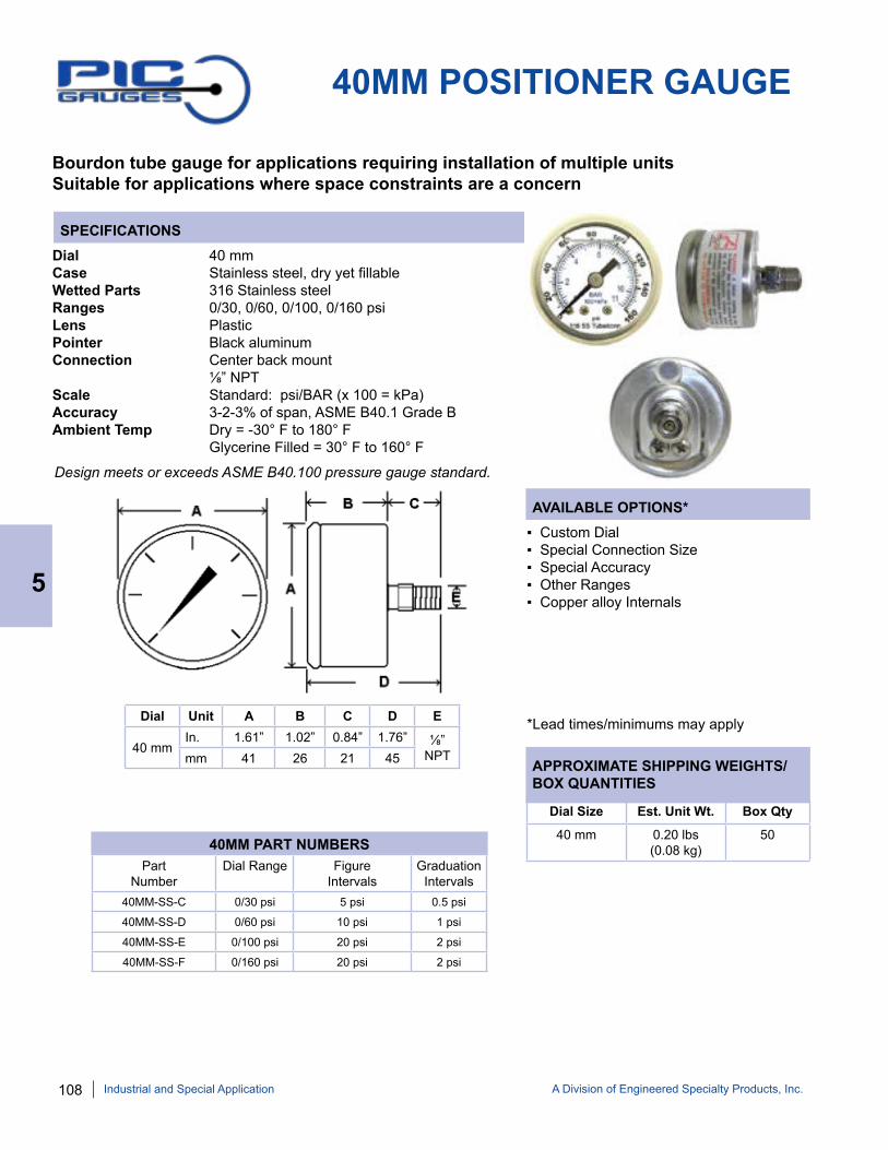
108 A Division of Engineered Specialty Products, Inc.
SPECIFICATIONS
AVAILABLE OPTIONS*
APPROXIMATE SHIPPING WEIGHTS/BOX QUANTITIES
5
Industrial and Special Application
40MM POSITIONER GAUGE
Bourdon tube gauge for applications requiring installation of multiple unitsSuitable for applications where space constraints are a concern
Dial 40 mmCase Stainless steel, dry yet fillableWetted Parts 316 Stainless steelRanges 0/30, 0/60, 0/100, 0/160 psiLens PlasticPointer Black aluminumConnection Center back mount ⅛” NPTScale Standard: psi/BAR (x 100 = kPa)Accuracy 3-2-3% of span, ASME B40.1 Grade BAmbient Temp Dry = -30° F to 180° F Glycerine Filled = 30° F to 160° F
▪ Custom Dial▪ Special Connection Size▪ Special Accuracy▪ Other Ranges▪ Copper alloy Internals
*Lead times/minimums may applyDial Unit A B C D E
40 mm In. 1.61” 1.02” 0.84” 1.76” ⅛”
NPTmm 41 26 21 45
Dial Size Est. Unit Wt. Box Qty
40 mm 0.20 lbs (0.08 kg)
50
Part Number
Dial Range Figure Intervals
GraduationIntervals
40MM-SS-C 0/30 psi 5 psi 0.5 psi
40MM-SS-D 0/60 psi 10 psi 1 psi
40MM-SS-E 0/100 psi 20 psi 2 psi
40MM-SS-F 0/160 psi 20 psi 2 psi
40MM PART NUMBERS
Design meets or exceeds ASME B40.100 pressure gauge standard.

A Division of Engineered Specialty Products, Inc. 109Industrial and Special Application
5
ANTI-VIBRATION MOVEMENT
Creates liquid filled performance in a dry gaugeSuitable for rugged applications requiring dry gauges
A silicone dampened counter weight is attached to the movement, which creates a dampening effect similar to liquid filling, but without the cost and potential problems associated with liquid filling (i.e. browning and leakage).
ANTI-VIBRATION MOVEMENT
ANTI-VIBRATION ADVANTAGES
1. High Temp/Low Temp Applications Eliminates risk of liquid filling browning, baking or boiling Removes concern of liquid filling freezing
2. Clean Environment Applications Prevents liquid filling from leaking
3. Low Cost Applications Less expensive gauge can be used (i.e. steel case vs. stainless steel case)
AVAILABLE OPTIONS*
• Various Sizes and Configurations• Custom Dials• Special Connection Sizes• Various Ranges• Repairable
*Lead times/minimums may apply
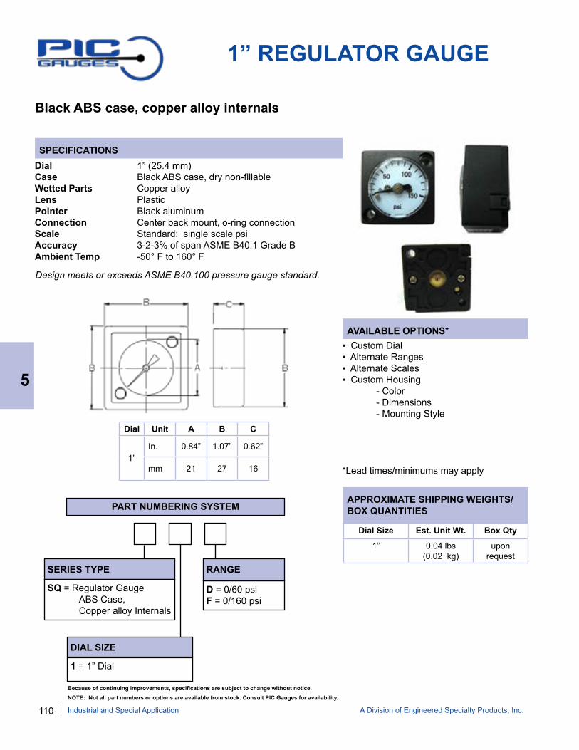
110 A Division of Engineered Specialty Products, Inc.
SPECIFICATIONS
AVAILABLE OPTIONS*
APPROXIMATE SHIPPING WEIGHTS/BOX QUANTITIES
Black ABS case, copper alloy internals
Dial 1” (25.4 mm)Case Black ABS case, dry non-fillableWetted Parts Copper alloy Lens Plastic Pointer Black aluminumConnection Center back mount, o-ring connectionScale Standard: single scale psi Accuracy 3-2-3% of span ASME B40.1 Grade BAmbient Temp -50° F to 160° F
Dial Unit A B C
1”In. 0.84” 1.07” 0.62”
mm 21 27 16
▪ Custom Dial▪ Alternate Ranges▪ Alternate Scales▪ Custom Housing - Color - Dimensions - Mounting Style
*Lead times/minimums may apply
Design meets or exceeds ASME B40.100 pressure gauge standard.
1” REGULATOR GAUGE
Dial Size Est. Unit Wt. Box Qty
1” 0.04 lbs (0.02 kg)
upon request
SERIES TYPE
SQ = Regulator Gauge ABS Case, Copper alloy Internals
DIAL SIZE
1 = 1” Dial
RANGE
D = 0/60 psi F = 0/160 psi
PART NUMBERING SYSTEM
5
Industrial and Special Application
Because of continuing improvements, specifications are subject to change without notice. NOTE: Not all part numbers or options are available from stock. Consult PIC Gauges for availability.

A Division of Engineered Specialty Products, Inc. 111
SPECIFICATIONS
AVAILABLE OPTIONS*
APPROXIMATE SHIPPING WEIGHTS/BOX QUANTITIES
FILTER GAUGE
Utility gauge with color zones for optimal filter performanceBlack steel case and bezel, copper alloy internals
Dial 1 ½” (40 mm), 2” (50 mm)Case Black steel, dry non-fillable Wetted Parts Copper alloyRanges 30/0” hg Vacuum, 0/60 psiBezel Black painted steel, fixedLens GlassPointer Black aluminumConnection Center back mount 1 ½” dial = ⅛” NPT 2” dial = ⅛” NPTScale Standard: psi/BAR (x 100 = kPa)Accuracy 3-2-3% of span, ASME B40.1 Grade BAmbient Temp -50° F to 160° F
▪ Certificate of Accuracy, NIST traceable ▪ Custom Dial▪ Custom Range▪ Anti-Vibration Movement, see page 109▪ Cleaned for Oxygen Service▪ Special Connection Size▪ Protective Rubber Cover, see page 121▪ Plastic Lens▪ Max/Min Pointer, see page 122
*Lead times/minimums may apply
Dial Size Est. Unit Weight
Box Qty
1 ½” 0.15 lbs(0.06 kg)
100
2” 0.25 lbs(0.10 kg)
100
Dial Unit A B C D E
1 ½” In. 1.64” 0.93” 0.63” 1.56”
⅛” NPTmm 42 24 16 39
2”In. 2.07” 1.03” 0.83” 1.86”
⅛” NPTmm 53 26 21 47
Color ZonesPart Number Range Green Yellow Red
FILTER-158D-CZ1 0/60 psi 0-20 20-25 25-60
FILTER-208A-CZ1 30/0” hg vac 0-9 9-11 11-30
FILTER-208A-CZ2 30/0” hg vac 0-4 4-6 6-30
FILTER-208D-CZ1 0/60 psi 0-20 20-25 25-60
STANDARD PART NUMBERS
Industrial and Special Application
5
Design meets or exceeds ASME B40.100 pressure gauge standard.

112 A Division of Engineered Specialty Products, Inc.
A14 ▪ Ball valve type gauge cock ▪ ¼” FNPT X ¼” FNPT ▪ Brass body rating: 700 psi at 250° F ▪ Est. Unit Wt.: 0.10 lbs/0.06 kg
GAUGE VALVES
MINI BALL VALVES
A15 ▪ Ball valve type gauge cock ▪ ¼” MNPT X ¼” FNPT ▪ Brass body rating: 700 psi at 250° F ▪ Est. Unit Wt.: 0.10 lbs/0.06 kg
BRASS NEEDLE VALVES
Unit A BIn. 1.60” 1.30”mm 40 33
Unit A BIn. 1.60” 1.35”mm 40 346
Accessories
NV-B-1/4 ▪ Needle valve ▪ ¼” FNPT X ¼” FNPT (NV-B-1/4-FXF) ▪ ¼” MNPT X ¼” FNPT (NV-B-1/4-MXF) ▪ ¼” MNPT X ¼” MNPT (NV-B-1/4-MXM) ▪ Brass body rating: 600 psi @ 300 °F ▪ Est. Unit Wt.: 0.25 lbs/0.10 kg
Unit A BIn. 1.62” 1.94”mm 41 49
Configuration Box QtyFXF 80MXF 200MXM 20

A Division of Engineered Specialty Products, Inc. 113
GAUGE COCKS
T-HANDLE COCK - A10 Material Polished brass Pressure Rating Up to 125 psi hydraulic Connection Size ¼” FNPT X ¼” FNPT Est. Unit Wt. 0.15 lbs/0.06 kg
GAUGE VALVES
LEVER HANDLE - A11 Material Polished Brass Pressure Rating Up to 200 psi hydraulic Connection Size ¼” MNPT X ¼” FNPT Est. Unit Wt. 0.15 lbs/0.06 kg
LEVER HANDLE - A12 Material Polished Brass Pressure Rating Up to 200 psi hydraulic Connection Size ¼” FNPT X ¼” FNPT Est. Unit Wt. 0.15 lbs/0.06 kg
6
Accessories

114 A Division of Engineered Specialty Products, Inc.
SYPHON
SPECIFICATIONSPurpose Syphons protect instruments from effects of hot pressure media commonly used in steam applicationsMaterials Brass Steel schedule 40 Steel schedule 80 316 Stainless steel schedule 80
STRAIGHT (180°) ANGLE (90°)
Part Number Description Maximum Working Pressure
Max Temp
Est. Unit Wt.
lbs
Est. Unit Wt.
kgA03B Straight ¼” NPT Brass syphon 250 psi 400° F 0.45 0.20A031 Straight ¼” NPT iron syphon, schedule 40 iron 500 psi 400° F 0.50 0.24CPS4 Straight ¼” NPT steel syphon, schedule 80 iron 1000 psi 850° F 0.55 0.24CPS4-ANGLE Angle ¼” NPT steel syphon, schedule 80 iron 1000 psi 850° F 0.45 0.20CPS2 Straight ½” NPT steel syphon, schedule 80 iron 1000 psi 850° F 1.70 0.76CPSS4 Straight ¼” NPT stainless steel syphon, 316 ss sched 80 2000 psi 1000° F 0.50 0.22CPSS2 Straight ½” NPT stainless steel syphon, 316 ss sched 80 2000 psi 1000° F 1.65 0.74
6
Accessories
NOTE: Other configurations available upon request.

A Division of Engineered Specialty Products, Inc. 115
TEST PORT PLUG
SPECIFICATIONS
Purpose Pressure & Temperature Test Port Plugs For permanent installation into piping systemsConnection ⅛”, ¼”, ½” NPTMaterials Brass body Nordel corePressure Rating 1000 psi at 200° F Est. Unit Weight 0.15 lbs/0.08 kg
Part Number Nominal Size
Overall Length
Material Temperature/Pressure
Body Hex Cap Hex Core Material
PLUG-1/8 ⅛” NPT 1 ¼” Brass 350° F/1000 psi 13/16” 9/16” Nordel
PLUG-1/4 ¼” NPT 1 ½” Brass 350° F/1000 psi 1 1/16” 1 ½” Nordel
PLUG-1/2 ½” NPT 1 ½” Brass 350° F/1000 psi 1 1/16” 1 ½” Nordel
Adapters for Test Port PlugsADAPTER-PP-1/8 ⅛” NPT Gauge adapter 2 ¾” Overall Length x 1 ¾” x 0.125” probeADAPTER-PP-1/4 ¼” NPT Gauge adapter 2 ¾” Overall Length x 1 ¾” x 0.63” probe
6
Accessories
Pressure & Temperature Test Plug AccessoriesPLUG-EXT-1/4 1 ¾” Extension for Test Port Plug (¼” NPT)PLUG-EXT-1/2 2” Extension for Test Port Plug (½” NPT)

116 A Division of Engineered Specialty Products, Inc.
FILTER TYPE PRESSURE SNUBBER
SPECIFICATIONS
Purpose Dampens pressure pulsation and slows the effects of surges or sudden pressure spikes Can be disassembled for cleaningMedia Water, air, oil, gasConnection ⅛”, ¼” or ½” NPTMaterials Stainless steel, BrassDesign Type Porous element
6
Accessories
Part Number Description Units A B
Pressure Rating
BW42-1/8 ⅛” NPT MxF BrassInches 0.74” 1.35”
3,000 psimm 18.9 35
BW42 ¼” NPT MxF BrassInches 0.75” 1.70”
3,000 psimm 19 43.1
BW41-1/2 ½” NPT MxF BrassInches 1.25” 2.25”
10,000 psimm 31.7 57.1
SW42 ¼” NPT MxF Stainless Steel
Inches 0.75” 1.70”5,000 psi
mm 19 43.1
A05E ½” NPT MxF Stainless Steel
Inches 1.25” 2.25”10,000 psi
mm 31.7 57.1
Part Number
Est. Unit Wt. lbs
Est. Unit Wt. kg Box Qty.
BW42-1/8 0.10 0.04 upon request
BW42 0.10 0.04 500
BW41-1/2 0.25 0.12 upon request
SW42 0.10 0.04 500
A05E 0.25 0.12 upon request

A Division of Engineered Specialty Products, Inc. 117
ADJUSTABLE PRESSURESNUBBER
SPECIFICATIONS
Purpose Adjustable pressure pulsation dampener Additionally, flow control can be regulated via Adjustment knob Can isolate gauge for service or replacementConnection ¼” or ½” NPTMaterials 316 Stainless steelPressure Rating 6000 psi maximumEst. Unit Wt. 0.50 lbs/0.22 kg
6
Accessories
Part Number Units A B C D Maximum Pressure
Box Quantity
APS-316-4Inches
¼” NPT1.00” 2.05” 1.06”
6000 psi uponrequestmm 25 52 27
APS-316-2Inches
½” NPT1.18” 2.44” 1.06”
6000 psi 32mm 30 62 27

118 A Division of Engineered Specialty Products, Inc.
PISTON TYPE SNUBBER
SPECIFICATIONS
Purpose Self cleaning piston type snubber dampens pressure pulsation and slows the effects of surges or sudden pressure spikesMedia Water, air, oil, gasConnection ¼”, ⅜” or ½” NPTMaterials Brass, Stainless steelPressure Rating Brass = 3000 psi Stainless steel = 10,000 psi
Part Number* Inlet Outlet Body Material
Maximum psi Ln. Hex
PPS-B-1/4 ¼” NPT ¼” NPT Brass 3000 3.46” 0.75”PPS-S-1/4 ¼” NPT ¼” NPT 303 Stainless 5000 3.46” 0.75”PPS-SS-1/4 ¼” NPT ¼” NPT 316 Stainless 5000 3.46” 0.75”PPS-B-3/8 ⅜” NPT ⅜” NPT Brass 5000 3.61” 1.125”
PPS-B-1/2 ½” NPT ½” NPT Brass 5000 3.61” 1.125”PPS-S-1/2 ½” NPT ½” NPT 303 Stainless 10000 3.61” 1.125”PPS-SS-1/2 ½” NPT ½” NPT 316 Stainless 10000 3.61” 1.125”
*Available in British Taper Pipe Threads. Add “BSP” to part number when ordering. Lead times/minimums may apply.
6
Accessories

A Division of Engineered Specialty Products, Inc. 119
COOLING TOWER
SPECIFICATIONS
Purpose Designed to protect instruments in high temperature applications Can reduce media temps by up to 150° F, 200° F or 300° FConnection ¼” or ½” NPTMaterials Stainless steel - 316SSTemperature Rating Maximum 300° F/150° C - Cooling factor 150° F/65° C Maximum 400° F/200° C - Cooling factor 200° F/93° C Maximum 600° F/315° C - Cooling factor 300° F/150° C
6
Accessories
Cooling Factor
Units A B C
150° FIn 2.25” 1.06” ¼” or ½”
NPTmm 57 27
200° FIn 3.80” 1.07” ¼” or ½”
NPTmm 97 27
300° FIn 4.22” 1.58” ¼” or ½”
NPT mm 107 40
Cooling Factor
Est. Unit Wt.
lbs
Est. Unit Wt.
kg
150° F 0.55 0.24
200° F 0.65 0.28
300° F 1.20 0.54
SERIES TYPE
COOL
CONNECTION SIZE
2 = ½” NPT 4 = ¼” NPT
TEMP RATING 03 = 300° F Max/ cooling factor 150° F 04 = 400° F Max/ cooling factor 200° F 05 = 600° F Max/ cooling factor 300° F
PART NUMBERING SYSTEM
CONNECTION TYPE
F = Female M = Male
CONNECTION SIZE
2 = ½” NPT 4 = ¼” NPT
CONNECTION TYPE
F = Female M = Male
NOTE: Not all part numbers or options are available from stock. Consult PIC Gauges for availability.

120 A Division of Engineered Specialty Products, Inc.
PRESSURE LIMITING VALVE
SPECIFICATIONS
Purpose Prevent damage to instruments due to sudden pressure surgesMedia Water, air, oil, gasConnection ¼” or ½” NPTMaterials 316 Stainless steelPressure Rating 6000 psi maximumEst. Unit Weight 1.30 lbs/0.58 kg
6
Accessories
Part Number Inlet OutletPLV-2M-2F-(Range) ½” male ½” femalePLV-4M-4F-(Range) ¼” male ¼” female
Units A B C DInches 3.50” 1.10” 1.04” 3.14”mm 89 28 26.5 80 AVAILABLE OPTIONS*
▪ Special Connection Size - BSP - Metric - Flaired - UNF▪ Custom Configuration - Female x Female - Male x Male▪ Cleaned for Oxygen Service▪ Exotic Materials Include - Monel - Hastelloy C▪ Material Test Certificates▪ NACE Conformity
*Lead times/minimums may apply
Range Code Adjustment Span
1 60 to 87 psi 4 to 6 BAR2 102 to 232 psi 7 to 16 BAR3 145 to 580 psi 10 to 40 BAR4 435 to 1160 psi 30 to 80 BAR5 870 to 2320 psi 60 to 160 BAR6 1450 to 5802 psi 100 to 400 BAR

A Division of Engineered Specialty Products, Inc. 121
RUBBER GAUGE COVER
Purpose Designed to protect gauges in rugged environments Many standard configurations in stock Custom configurations/colors availableMaterials Rubber Compound Size 1 ½”, 2”, 2 ½”, 4 Connection Lower or Back Mount
SPECIFICATIONS
6
Accessories

122 A Division of Engineered Specialty Products, Inc.
EXAMPLES OF GAUGES WITH MAX/MIN POINTERS
MAX/MIN POINTER
SPECIFICATIONS
Purpose Indicate maximum or minimum pressure achieved in a pressurized system over a given periodLens Material Plastic or GlassDial Size 2 ½”, 4” or 4 ½” Connection Lower or Back MountMounting Direct or PanelCase Styles Dry or Liquid Filled
The max pointer is a red auxillary pointer with an arm that is pushed by the primary gauge pointer until the gauge pressure drops. The max pointer remains at peak pressure, indicating max pressure achieved.
Conversely, this unit can function similarly as a min pointer on vacuum or compound ranges.
Due to the added resistance of the max pointer, these cannot be used on low pressure gauges.
6
Accessories
STANDARD P/N* DESCRIPTIONMAX-25-DRY-GL Dry Non-Fillable 2 1/2” Max Pointer for 100 Series Utility Gauges -
Glass LensMAX-25-DRY-PL Dry Non-Fillable 2 1/2” Max Pointer for 100 Series Utility Gauges -
Plastic LensMAX-25-DRY-211311 Dry Non-Fillable 2 1/2” Max Pointer for 210 or 310 Series Gauges -
Plastic LensMAX-MIN-25-311D Liquid Fillable 2 1/2” Max/Min Pointer for 310 Series with 2 Red
Pointers - Plastic LensMAX-POINTER-311D Liquid Fillable 2 1/2” Max Pointer for 310 Series - Plastic LensMAX-POINTER-4001 Liquid Fillable 4” Max Pointer for 4001 Series - Plastic LensMAX-POINTER-4501 Liquid Fillable 4 1/2” Max Pointer for 4501 Phenolic Case - Plastic
Lens
*Custom dial sizes & configurations available upon request.

A Division of Engineered Specialty Products, Inc. 123
FRONT AND BACK FLANGES
Stainless steel flanges designed for use with pressure gaugesFront flanges can be used with center back mount (CBM) or lower back mount (LBM) connectionsBack flanges can be used with lower mount or back mount gauges
Accessories
6
DIMENSIONAL INFORMATIONA B C D E1 E2
PART NUMBER GAUGE MODELS FLANGE OD CASE RING OD CASE RING ID SCREW HOLE DIAMETER
ON DIAMETER CIRCLE
DISTANCE FROM DIAMETER
1 FLANGE-15-DRY 103D-158 2.22”/56.5 mm 1.66”/42 mm 1.60”/40.7 mm 0.117”/3 mm 1.91”/48 mm 0.96”/24 mm
2 FLANGE-15-LF 202L-158, 302L-158 2.46”/62.5 mm 1.72”/44 mm 1.62”/41 mm 0.125”/3 mm 1.93”/49 mm 0.97”/24.5 mm
3 FLANGE-15-NH 103D-158 2.22”/5.7 mm 1.66”/42 mm 1.60”/40.7 mm NONE N/A N/A
4 FLANGE-20 102D-20X, 103D-20X, 202L-20X, 302L-20X
2.81”/71.4 mm 2.08”/53 mm 2.02”/51.2 mm 0.125”/3 mm 2.34”/60 mm 1.17”/30 mm
5 FLANGE-25 202L-254, 212D-254 3.50”/89 mm 2.58”/65 mm 2.49”/63 mm 0.17”/4 mm 3.05”/77 mm 1.52”/39 mm
6 FLANGE-61MM-OBLONG S202L, 302DFW-254 3.48”/88 mm 2.44”/62 mm 2.38”/60.5 mm 0.17”/4.25 mm 3”/76 mm 1.5”/38 mm
7 FLANGE-62MM 103D-254, SEC-202L-254, 302DFW-254, SEC-302DFW-254
3.46”/88 mm 2.50”/63.6 mm 2.44”/62 mm 0.18”/4.6 mm 2.98”/75.7 mm 1.49”/37.9 mm
8 FLANGE-62MM-NH
9 FLANGE-64MM-NH 103D-254, SEC-202L-254, 302DFW-254, SEC-302DFW-254
3.43”/87 mm 2.88”/66 mm 2.52”/64 mm NONE N/A N/A
10 FLANGE-35 203D-354 5.17”/131 mm 3.56”/90 mm 3.45”/88 mm 0.21”/5.3 mm 4.57”/116 mm 2.28”/58 mm
11 FLANGE-4 202L-40X 5.14”/130 mm 4.02”/102 mm 3.90”/99 mm 0.22”/5.8 mm 4.49”/114 mm 2.25”/57 mm
12 FLANGE-60 6002, AMMONIA-604 7.63”/193.7 mm 6.35”/161.3 mm 6.25”/158.8 mm 0.188”/4.8 mm 7”/177.8 mm 3.5”/89 mm
13 BACK FLANGE-25 201L-254, 301LFW-254, 202L-254, 211D-254, 311D-254
3.42”/87 mm 2.58”/65 mm 2.46”/62 mm 0.17”/4.3 mm 2.99”/76 mm 1.50”/38 mm
14 BACK FLANGE-25-SEC SEC-201L-254, SEC-202L-254 3.12”/79 mm 2.53”/64 mm 2.44”/62 mm 0.17”/4.3 mm 3.14”/80 mm 1.57”/40 mm
15 BACK FLANGE-4 201L, S201L, 301L 5.125”/130.2 mm 3.96”/100.6 mm 3.9”/99.1 mm 0.16”/4.1 mm 4.5”/114 mm 2.25”/57 mm
16 BACK FLANGE-40 4001, 314D 5.25”/133.4 mm 3.98”/100.9 mm 3.88”/98.4 mm 0.188”/4.8 mm 4.56”/116 mm 2.28”/58 mm
17 BACK FLANGE-60 6001, 6002 7.63”/193.7 mm 6.35”/161.3 mm 6.25”/158.8 mm 0.188”/4.8 mm 7”/177.8 mm 3.5”/89 mm
18 FLANGE TO ACCOMPANY P/N 314D-254(X) 3.45”/87.7mm 2.51”/63.7mm 2.43”/61.7mm 0.19”/5mm 3.16”/80.3mm 1.58”/40.1mm
19 FLANGE TO ACCOMPANY P/N 314D-404(X) 5.23”/132.9mm 3.95”/100.3mm 3.81”/96.9mm 0.18”/4.5mm 4.50”/114.3mm 2.25”/57.3mm
20 BACK FLANGE TO ACCOMPANY P/N 115D-454(X) 5.87”/149mm N/A N/A 0.27”/7mm 5.36”/136.4mm 2.68”/68.2mm
21 BACK FLANGE TO ACCOMPANY P/N 115D-604(X) 7.42”/188mm N/A N/A 0.27”/7mm 6.70”/170.6mm 3.35”/85.3mm
22 BACK FLANGE TO ACCOMPANY P/N 115D-854(X) 10.3”/260mm N/A N/A 0.23”/6mm 8.74”/222.2mm 4.37”/111.1mm

124 A Division of Engineered Specialty Products, Inc.Needle Valves
7
NEEDLE VALVES
Instrumentation grade needle valves are designed for heavy duty process applications or other industrial applications that require high pressure carbon steel or stainless steel shut off valves. PIC Gauges stocks a wide variety of needle valve configurations.
NVS “SUPER MINI”
NV/NVLNV-1/4 NV-90 ANGLE
HV HEX BODY
GV MULTI-PORTBV BLOCK & BLEED VALVE
PANEL MOUNT

A Division of Engineered Specialty Products, Inc. 125
NEEDLE VALVE PART NUMBERING SYSTEM
SERIES TYPE
NVS = “Super Mini” with thumbwheel NV-¼” = ¼” Mini with T-handle NVL = Full Size ¼” NPT NV-½” = Full Size ½” NPT HV = Hex Body Valve GV = Multi-Port Gauge Valve BV = Block & Bleed Valve
BODY MATERIAL
CS = Carbon Steel SS = 316 Stainless Steel
CONNECTION SIZE
¼ = ¼” NPT ⅜ = ⅜” NPT ½ = ½” NPT
SEAT/PRESSURE RATING
GS = Gas Service/6000 psi/ Soft Seat HS = Hydraulic Service/10,000 psi/Hard Seat
BODY PATTERN
180 = Straight 90 = Angle
INLET CONNECTION
F = Female M = Male
OUTLET CONNECTION
F = Female M = Male
EXAMPLE: “NVS-CS-1/4-GS-180-MXF”
NVS = “Super Mini” with thumbwheel CS = Carbon Steel ¼ = ¼” NPT GS = Gas Service/6000 psi/Soft Seat 180 = Straight M = Male Inlet X F = Female Outlet
X
Needle Valves
7
NOTE: Not all part numbers or options are available from stock. Consult PIC Gauges for availability.

126 A Division of Engineered Specialty Products, Inc.
SPECIFICATIONS Series Number “NVS” Material Carbon steel See chart below for component materials Pressure Rating Soft seat - 6000 psi at 200° F Connection Size ¼” NPT, male x female, female x female male x male Handle Round “thumb wheel” Seat Material Soft Seat - POM Box Quantity 80 pieces Est. Unit Weight 0.30 lb/0.16 kg
Part Number Unit A L L1 H H1 EThumb Wheel
NVS-CS-1/4-GS-180-MXF In. ¼” NPT
1.85” 0.93” 1.97” 0.75” 0.13” 1.02”
mm 47 23.5 50 19 3.3 26
NVS-CS-1/4-GS-180-FXF In. ¼” NPT
1.85” 0.93” 1.97” 0.75” 0.13” 1.02”
mm 47 23.5 50 19 3.3 26
NVS-CS-1/4-GS-180-MXM In. ¼” NPT
1.85” 0.93” 1.97” 0.75” 0.13” 1.02”
mm 47 23.5 50 19 3.3 26
▪ High Temperature▪ T-handle▪ Hard Seat▪ 316 SS Material▪ Angle Valve (90°)▪ Tube End Connection▪ Alternate Connection Sizes
*Lead times/minimums may apply
Strong and Durable, Super Compact Size Needle Valve Pressures up to 6,000 psi
Number Description
Carbon Steel Valve
1 Body C.S.
2 Bonnet C.S.
3 Stem 304 SS
4 Handle C.S.
5 Fixing Screw C.S.
6 O-Ring Viton®
7 O-Ring Viton®
8 Back-up Ring PTFE
9 Washer 316 SS
10 Soft Seat POM
NVS “SUPER MINI” NEEDLE VALVE
AVAILABLE OPTIONS*
7
Needle Valves
All dimensions shown in the catalog are approximate and subject to change.

A Division of Engineered Specialty Products, Inc. 127
SPECIFICATIONS
AVAILABLE OPTIONS*
Series Number “NV” Material Carbon steel or 316 stainless steel See chart below for component materials Pressure Rating Soft seat - 6000 psi at 200° F Hard seat - 10,000 psi at 200° F Connection Size ¼” NPT, male x female, female x female male x male Handle Tee Seat Material Soft Seat - POM Hard Seat - Integrated Box Quantity 60 pieces Est. Unit Weight 0.40 lb/0.20 kg
▪ High Temperature▪ Thumb Wheel Handle▪ Panel Mount▪ Bleed Screw▪ Tube End Connection▪ Alternate Connection Sizes
*Lead times/minimums may apply
NV-¼ MINI NEEDLE VALVE
Strong and Durable, Compact Size Needle ValvePressures up to 6,000 psi soft seat, 10,000 psi hard seat
Number Description316 Valve
Carbon Steel Valve
1 Body 316 SS C.S.
2 Bonnet 316 SS C.S.
3 Stem 316 SS 304 SS
4 Handle 303 SS C.S.
5 Fixing Screw 302 SS C.S.
6 Lock Pin 303 SS C.S.
7 O-Ring Viton® Viton®
8 Back-up Ring PTFE PTFE
9 Dust Cap NBR NBR
7
Needle Valves
Part Number Unit A L L1 H H1 E WNV-SS-1/4-GS-180-MXF NV-SS-1/4-GS-180-FXFNV-SS-1/4-HS-180-MXFNV-SS-1/4-HS-180-FXFNV-CS-1/4-GS-180-MXFNV-CS-1/4-GS-180-MXMNV-CS-1/4-GS-180-FXFNV-CS-1/4-HS-180-MXFNV-CS-1/4-HS-180-FXF
In.
¼” NPT
2.28” 1.14” 2.48” 0.75” 0.17” 1.81”
mm 58 29 63 19 4.2 46
All dimensions shown in the catalog are approximate and subject to change.

128 A Division of Engineered Specialty Products, Inc.
SPECIFICATIONS
Series Number “NV” or “NVL” (¼”) Material Carbon steel or 316 stainless steel See chart below for component materials Pressure Rating Soft seat - 6000 psi at 200° F Hard seat - 10,000 psi at 200° F Connection Size NV - ½” NPT, ⅜” NPT (316 SS only) NVL - ¼” NPT For ¾” or 1” sizes, see HV series page 130-131 male x female, female x female Handle Tee Seat Material Soft Seat - POM Box Quantity 15 pieces Est. Unit Weight 1.20 lb/0.54 kg
NV/NVL FULL SIZE NEEDLE VALVE
Strong and Durable, Full Size Needle Valve Pressures up to 6,000 psi soft seat, 10,000 psi hard seat
AVAILABLE OPTIONS*▪ High Temperature▪ Panel Mount▪ Bleed Screw▪ Tube End Connection▪ Alternate Connection Sizes▪ See HV for Additional Configurations, p. 124-125
*Lead times/minimums may apply
Number Description316 Valve
Carbon Steel Valve
1 Body 316 SS C.S.
2 Bonnet 316 SS C.S.
3 Stem 316 SS 304 SS
4 Handle 303 SS C.S.
5 Fixing Screw 302 SS C.S.
6 Lock Pin 303 SS C.S.
7 O-Ring Viton® Viton®
8 Back-up Ring PTFE PTFE
9 Dust Cap NBR NBR
7
Needle Valves
All dimensions shown in the catalog are approximate and subject to change.
Soft Seat Part Number Unit A L L1 H H1 E WNVL-SS-1/4-GS-180-MXFNVL-CS-1/4-GS-180-MXFNV-SS-3/8-GS-180-MXFNV-SS-1/2-GS-180-MXFNV-CS-1/2-GS-180-MXF
In. ¼”, ⅜”, ½”
NPT
3.23” 1.38” 3.03” 1.14” 0.18” 2.24”
mm 82 35 77 29 4.5 57
NVL-CS-1/4-GS-180-FXFNV-SS-3/8-GS-180-FXFNV-SS-1/2-GS-180-FXFNV-CS-1/2-GS-180-FXF
In. ¼”, ⅜”, ½”
NPT
2.95” 1.38” 3.03” 1.14” 0.18” 2.24”
mm 75 35 77 29 4.5 57
Hard Seat Part Number Unit A L L1 H H1 E W
NVL-SS-1/4-HS-180-MXFNVL-CS-1/4-HS-180-MXFNV-SS-3/8-HS-180-MXFNV-CS-1/2-HS-180-MXFNV-SS-1/2-HS-180-MXF
In. ¼”, ⅜”, ½”
NPT
3.23” 1.38” 3.03” 1.14” 0.24” 2.24”
mm 82 35 77 29 6 57
NV-SS-3/8-HS-180-FXFNV-CS-1/2-HS-180-FXFNV-SS-1/2-HS-180-FXF
In.⅜”, ½”
NPT
2.95” 1.48” 3.03” 1.14” 0.24” 2.24”
mm 75 37.5 77 29 6 57
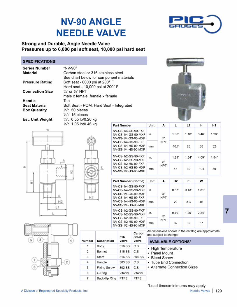
A Division of Engineered Specialty Products, Inc. 129
SPECIFICATIONS
AVAILABLE OPTIONS*
NV-90 ANGLE NEEDLE VALVE
Strong and Durable, Angle Needle ValvePressures up to 6,000 psi soft seat, 10,000 psi hard seat
Series Number “NV-90” Material Carbon steel or 316 stainless steel See chart below for component materials Pressure Rating Soft seat - 6000 psi at 200° F Hard seat - 10,000 psi at 200° F Connection Size ¼” or ½” NPT male x female, female x female Handle Tee Seat Material Soft Seat - POM; Hard Seat - Integrated Box Quantity ¼”: 50 pieces ½”: 15 pieces Est. Unit Weight ¼”: 0.55 lb/0.26 kg ½”: 1.05 lb/0.46 kg
Number Description316 Valve
Carbon Steel Valve
1 Body 316 SS C.S.
2 Bonnet 316 SS C.S.
3 Stem 316 SS 304 SS
4 Handle 303 SS C.S.
5 Fixing Screw 302 SS C.S.
6 O-Ring Viton® Viton®
7 Back-Up Ring PTFE PTFE
Part Number Unit A L L1 H H1
NV-CS-1/4-GS-90-FXFNV-CS-1/4-GS-90-MXFNV-SS-1/4-GS-90-MXFNV-CS-1/4-HS-90-FXFNV-CS-1/4-HS-90-MXFNV-SS-1/4-HS-90-MXF
In.¼”
NPT
1.60” 1.10” 3.46” 1.26”
mm 40.7 28 88 32
NV-CS-1/2-GS-90-FXFNV-CS-1/2-GS-90-MXFNV-CS-1/2-HS-90-FXFNV-CS-1/2-HS-90-MXFNV-SS-1/2-HS-90-MXF
In. ½”
NPT
1.81” 1.54” 4.09” 1.54”
mm 46 39 104 39
▪ High Temperature▪ Panel Mount▪ Bleed Screw▪ Tube End Connection▪ Alternate Connection Sizes
*Lead times/minimums may apply
Part Number (Cont’d) Unit A H2 E WNV-CS-1/4-GS-90-FXFNV-CS-1/4-GS-90-MXFNV-SS-1/4-GS-90-MXFNV-CS-1/4-HS-90-FXFNV-CS-1/4-HS-90-MXFNV-SS-1/4-HS-90-MXF
In.¼”
NPT
0.87” 0.13” 1.81”
mm 22 3.3 46
NV-CS-1/2-GS-90-FXFNV-CS-1/2-GS-90-MXFNV-CS-1/2-HS-90-FXFNV-CS-1/2-HS-90-MXFNV-SS-1/2-HS-90-MXF
In. ½”
NPT
0.79” 1.26” 2.24”
mm 32 32 57
7
Needle Valves
All dimensions shown in the catalog are approximate and subject to change.

130 A Division of Engineered Specialty Products, Inc.
SPECIFICATIONS
AVAILABLE OPTIONS*
HV HEX BODY - SOFT SEATNEEDLE VALVE
Strong and durable, instrument grade hex body needle valve with soft seatPressures up to 6,000 psi soft seat
Series Number “HV” Material Carbon steel or 316 stainless steel body Pressure Rating Soft seat - 6000 psi at 200° F Connection Size ¼”, ½”, ¾” or 1” NPT male x female, female x female Handle Tee Seat Material Soft Seat - POM Box Quantity Standard: 15 pieces; 1”: 10 pieces Est. Unit Weight Standard: 1.25 lb/0.58 kg; 1”: 1.75 lb/0.80 kg
Soft Seat Part Numbers Unit L L1 H H1 E WHV-(X)S-1/4-GS-180-MXF 1/4” NPTHV-(X)S-1/2-GS-180-MXF 1/2” NPTHV-(X)S-3/4-GS-180-MXF 3/4” NPT
In. 3.2” 1.4” 3.9” 1.3” 0.2” 2.2”
mm 82 35 98 32 6 57
HV-(X)S-1/4-GS-180-FXF 1/4” NPTHV-(X)S-1/2-GS-180-FXF 1/2” NPTHV-(X)S-3/4-GS-180-FXF 3/4” NPT
In. 3.0” 1.5” 3.9” 1.3” 0.2” 2.2”
mm 75 37.5 98 32 6 57
HV-(X)S-1-GS-180-MXF 1” NPT In. 3.7” 1.6” 4.4” 1.6” 0.3” 2.2”
mm 95 41.5 112 41 7 57
HV-(X)S-1-GS-180-FXF 1” NPT In. 3.1” 1.6” 4.4” 1.6” 0.3” 2.2”
mm 80 40 112 41 7 57
▪ High Temperature▪ NACE▪ Tube End Connection▪ Alternate Connection Sizes
*Lead times/minimums may apply
Number Description316SSValve
Carbon Steel Valve
1 Body S316 C.S.
2 Bonnet S316 C.S.
3 Stem S316 S304
4 Adjuster S316 C.S.
5 Lock Nut S316 C.S.
6 Handle S303 C.S.
7 Fixing Screw S302 C.S.
8 Stem Seal PTFE PTFE
9 Stem Seal Viton® Viton®
10 Dust Cap NBR NBR
11 Soft Seat POM POM
12 Locking Pin S303 S303
(X)= C or SC = Carbon SteelS = 316 Stainless Steel
7
Needle Valves
All dimensions shown in the catalog are approximate and subject to change.

A Division of Engineered Specialty Products, Inc. 131
SPECIFICATIONS
HV HEX BODY - HARD SEATNEEDLE VALVE
Strong and durable, instrument grade hex body needle valve with hard seatPressures up to 10,000 psi hard seat
Series Number “HV” Material Carbon steel or 316 stainless steel body Pressure Rating Hard seat - 10,000 psi at 200° F Connection Size ¼”, ½”, ¾” or 1” NPT male x female, female x female Handle Tee Box Quantity Standard: 15 pieces; 1”: 10 pieces Est. Unit Weight Standard: 1.25 lb/0.58 kg; 1”: 1.75 lb/0.80 kg
Hard Seat Part Number Unit L L1 H H1 E WHV-(X)S-1/4-HS-180-MXF 1/4” NPTHV-(X)S-1/2-HS-180-MXF 1/2” NPTHV-(X)S-3/4-HS-180-MXF 3/4” NPT
In. 3.2” 1.4” 3.9” 1.3” 0.2” 2.2”
mm 82 35 98 32 4.8 57
HV-(X)S-1/4-HS-180-FXF 1/4” NPTHV-(X)S-1/2-HS-180-FXF 1/2” NPTHV-(X)S-3/4-HS-180-FXF 3/4” NPT
In. 3.0” 1.5” 3.9” 1.3” 0.2” 2.2”
mm 75 37.5 98 32 4.8 57
HV-(X)S-1-HS-180-MXF 1” NPT In. 3.7” 1.6” 4.4” 1.6” 0.3” 2.2”
mm 95 41.5 112 41 7 57
HV-(X)S-1-HS-180-FXF 1” NPT In. 3.1” 1.6” 4.4” 1.6” 0.3” 2.2”
mm 80 40 112 41 7 57
Number Description316SSValve
Carbon Steel Valve
1 Body S316 C.S.
2 Bonnet S316 C.S.
3 Stem S316 S304
4 Adjuster S316 C.S.
5 Lock Nut S316 C.S.
6 Handle S303 C.S.
7 Fixing Screw S302 C.S.
8 Stem Seal PTFE PTFE
9 Stem Seal Viton® Viton®
10 Dust Cap NBR NBR
11 Locking Pin S303 S303
AVAILABLE OPTIONS*▪ High Temperature▪ NACE▪ Tube End Connection▪ Alternate Connection Sizes
*Lead times/minimums may apply
(X)= C or SC = Carbon SteelS = 316 Stainless Steel
7
Needle Valves
All dimensions shown in the catalog are approximate and subject to change.

132 A Division of Engineered Specialty Products, Inc.
SPECIFICATIONS
Needle Valves
AVAILABLE OPTIONS*
BV BLOCK & BLEED VALVE
Series Number “BV” Material 316 Stainless steel body Pressure Rating 6000 psi soft seat 10,000 psi hard seat Connection Size ¼” NPT or ½” NPT male x female Handle Tee Seat Material Soft Seat - POM Hard Seat - Integrated Box Quantity 15 Est. Unit Weight 1.25 lb/0.56 kg
▪ High Temperature▪ Tube End Connection▪ Alternate Connection Sizes▪ Carbon Steel Material▪ Female x Female Connection
*Lead times/minimums may apply
Number Description316SSValve
1 Body S316
2 Bonnet S316
3 Stem S316
4 Adjuster S316
5 Lock Nut S316
6 Handle S303
7 Fixing Screw S302
8 Stem Seal PTFE
9 Stem Seal Viton®
10 Dust Cap NBR
11 Soft Seat POM
12 Locking Pin S303
13 Bleeding Screw
S316
Strong and durable, instrument grade hex body needle valve with bleed screwPressures up to 6,000 psi soft seat, 10,000 psi hard seat
7
Part Number Unit A L L1 HBV-SS-1/2-HS-180-MXFBV-SS-1/4-HS-180-MXF BV-SS-1/2-GS-180-MXFBV-SS-1/4-GS-180-MXF
In. 1/4” or
1/2”
3.23” 1.38” 1.50”
mm 82 35 98
Part Number (Cont’d) Unit H1 E WBV-SS-1/2-HS-180-MXF BV-SS-1/4-HS-180-MXFBV-SS-1/2-GS-180-MXFBV-SS-1/4-GS-180-MXF
In. 1.26” 0.18” 2.24”
mm 32 4.8 57
All dimensions shown in the catalog are approximate and subject to change.
Part Number Unit A L L1 HBV-SS-1/2-HS-180-FXFBV-SS-1/4-HS-180-FXF
In. 1/4” or
1/2”
2.95” 1.47” 1.50”
mm 75 37.5 98
Part Number (Cont’d) Unit H1 E WBV-SS-1/2-HS-180-FXFBV-SS-1/4-HS-180-FXF
In. 1.26” 0.18” 2.24”
mm 32 4.8 57

A Division of Engineered Specialty Products, Inc. 133
SPECIFICATIONS
AVAILABLE OPTIONS*
GV MULTI-PORTGAUGE VALVE
Strong and durable, instrument grade multi-port gauge valvePressures up to 6,000 psi soft seat, 10,000 psi hard seat
Series Number “GV” Material 316 Stainless steel body Pressure Rating 6000 psi soft seat 10,000 psi hard seat Connection Size ½” NPT male inlet x (3) ½” NPT female outlet ¾” NPT male inlet x (3) ½” NPT female outlet Handle Tee Seat Material Soft Seat - POM Hard Seat - Integrated Box Quantity 12 Est. Unit Weight 1.80 lb/0.80 kg
▪ High Temperature▪ Bleed Valve▪ Hex Plug▪ Tube End Connection▪ Alternate Connection Sizes▪ Carbon Steel Material
*Lead times/minimums may apply
Part Number Unit A L L1 L2 H H1 E WGV-SS-1/2-HS-3W-MXFGV-SS-3/4-HS-3W-MXF
In. 1/2” or
3/4”
4.45” 2.50” 1.42” 3.86” 1.26” 0.24” 2.24”
mm 113 63.5 36 98 32 6 57
GV-SS-1/2-GS-3W-MXFGV-SS-3/4-GS-3W-MXF
In. 1/2” or
3/4”
4.45” 2.50” 1.42” 3.86” 1.26” 0.19” 2.24”
mm 113 63.5 36 98 32 4.8 57
7
Needle Valves
P/N: BLEED VALVE
OPTIONAL BLEED VALVE ACCESSORY
All dimensions shown in the catalog are approximate and subject to change.

134 A Division of Engineered Specialty Products, Inc.Diaphragm Seals
8
DIAPHRAGM SEALS
Diaphragm seals, also referred to as isolators or chemical seals, are used to protect instruments from viscous, corrosive or very high temperature process media. PIC Gauges stocks, fills and cali-brates complete diaphragm seal assemblies in a wide variety of configurations.
M3500 SERIES MINI SEALS
Low cost for small instrumentsDial size up to 3 ½”
MLP SERIES MINI LOW PRESSURE
Large area diaphragm for low pressures & vacuum
M4500 SERIES MINI SEALS
Low cost for medium to large Dial size up to 4 ½”
MHP SERIESMINI HIGH PRESSURE
Mini diaphragm seal for pressures up to 6000 psi
LARGE THREADEDMost versatile for all
applications
SANITARYTri-Clamp® /Cherry-Burrell®, etc.
Food & pharmaceutical Designed for easy cleaning
THREADED FLUSHMini seal - threaded male
connection with flush diaphragm
FLANGED CONNECTIONRaised face or flat face
pressure from 150# to 2500#
SADDLE WELDWeld-in saddle mount
SPECIAL SEALSPTFE, homogenizer,
single flange or other custom designs
FILLING/CALIBRATIONUsing any fill fluid suitable for the application.
See page 151 for available options.
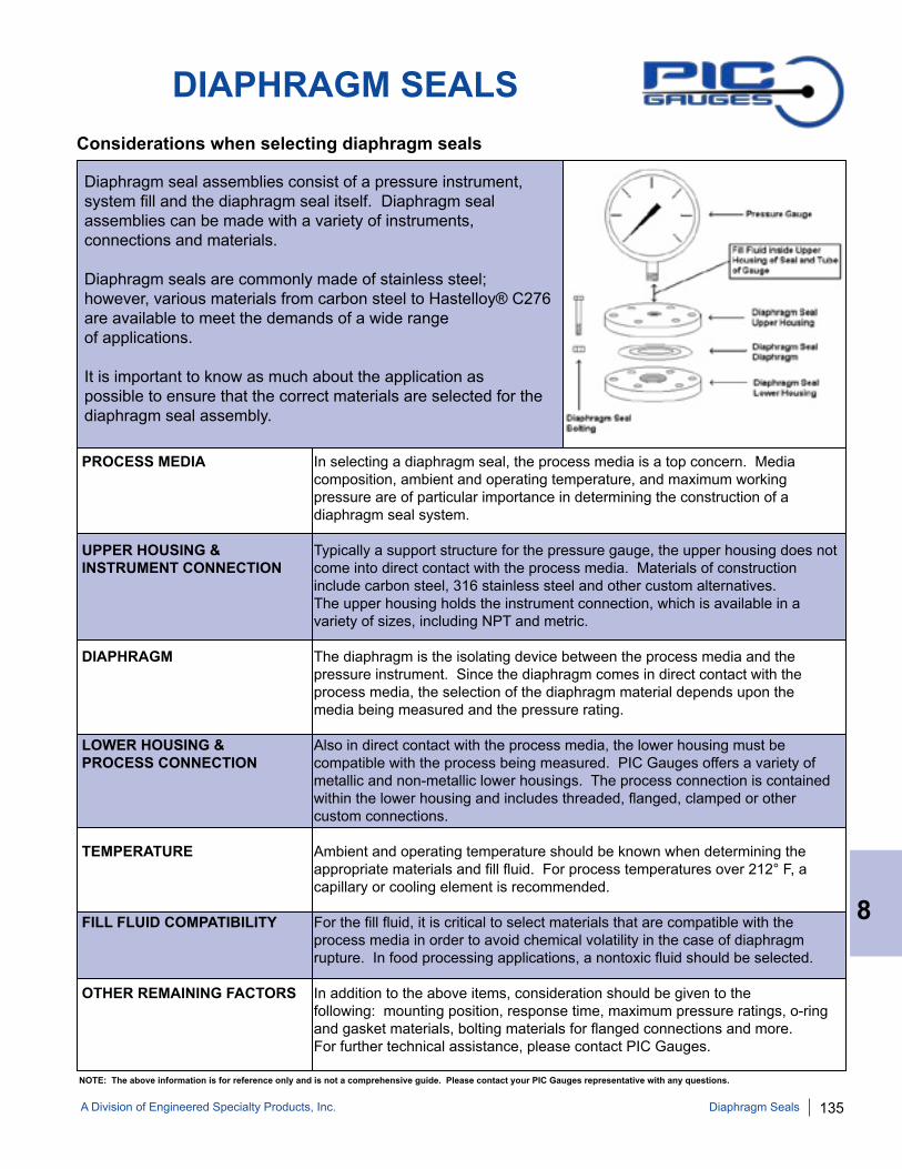
A Division of Engineered Specialty Products, Inc. 135
DIAPHRAGM SEALS
Diaphragm seal assemblies consist of a pressure instrument, system fill and the diaphragm seal itself. Diaphragm seal assemblies can be made with a variety of instruments, connections and materials.
Diaphragm seals are commonly made of stainless steel; however, various materials from carbon steel to Hastelloy® C276 are available to meet the demands of a wide range of applications.
It is important to know as much about the application as possible to ensure that the correct materials are selected for the diaphragm seal assembly.
Considerations when selecting diaphragm seals
NOTE: The above information is for reference only and is not a comprehensive guide. Please contact your PIC Gauges representative with any questions.
PROCESS MEDIA In selecting a diaphragm seal, the process media is a top concern. Media composition, ambient and operating temperature, and maximum working pressure are of particular importance in determining the construction of a diaphragm seal system.
UPPER HOUSING & Typically a support structure for the pressure gauge, the upper housing does not INSTRUMENT CONNECTION come into direct contact with the process media. Materials of construction include carbon steel, 316 stainless steel and other custom alternatives. The upper housing holds the instrument connection, which is available in a variety of sizes, including NPT and metric. DIAPHRAGM The diaphragm is the isolating device between the process media and the pressure instrument. Since the diaphragm comes in direct contact with the process media, the selection of the diaphragm material depends upon the media being measured and the pressure rating.
LOWER HOUSING & Also in direct contact with the process media, the lower housing must be PROCESS CONNECTION compatible with the process being measured. PIC Gauges offers a variety of metallic and non-metallic lower housings. The process connection is contained within the lower housing and includes threaded, flanged, clamped or other custom connections.
TEMPERATURE Ambient and operating temperature should be known when determining the appropriate materials and fill fluid. For process temperatures over 212° F, a capillary or cooling element is recommended.
FILL FLUID COMPATIBILITY For the fill fluid, it is critical to select materials that are compatible with the process media in order to avoid chemical volatility in the case of diaphragm rupture. In food processing applications, a nontoxic fluid should be selected.
OTHER REMAINING FACTORS In addition to the above items, consideration should be given to the following: mounting position, response time, maximum pressure ratings, o-ring and gasket materials, bolting materials for flanged connections and more. For further technical assistance, please contact PIC Gauges.
8
Diaphragm Seals

136 A Division of Engineered Specialty Products, Inc.
MINI DIAPHRAGM SEAL PART NUMBERING SYSTEM
SERIES TYPE
M35 = M3500 Series M45 = M4500 Series MHP = Mini High Pressure MLP = Mini Low Pressure
INSTRUMENT CONNECTION
1 = ¼” FNPT 2 = ½” FNPT
PROCESS CONNECTION
1 = ¼” FNPT 2 = ½” FNPT 3 = ¾” FNPT 4 = 1” FNPT
MATERIAL OF CONSTRUCTION1
316 = 316 Stainless Steel CAR = Carpenter 20® HTC = Hastelloy® C276 MON = Monel® TAN = Tantalum X = Other
FLUSHING CONNECTION
0 = No flushing connection F = With ¼” flushing connection
EXAMPLE: “DS-M3512-316-F”2
DS = Diaphragm Seal M35 = M3500 Series 1 = ¼” FNPT 2 = ½” FNPT 316 = 316 Stainless steel F = With ¼” flushing connection
DS / OPTION
M = Male threaded process connection
8
Diaphragm Seals
Notes: 1. Consult PIC Gauges for other materials of construction. 2. Not all part numbers or options are available from stock. Consult PIC Gauges for availability.

A Division of Engineered Specialty Products, Inc. 137
M3500 SERIESMINI DIAPHRAGM SEAL
SPECIFICATIONS
Threaded mini diaphragm seal for dial sizes up to 3 ½”Compact, durable all-welded construction
Design Diaphragm, upper and lower housing welded Instruments Gauges, pressure transducers, transmittersAppropriate Dial Size 1 ½” (38 mm) through 3 ½” (88.9 mm)Pressures 60 psi through 2500 psiUpper Housing Standard: 316 stainless steel Optional: Monel®, Hastelloy® C276, TantalumDiaphragm Standard: 316 stainless steel Optional: Monel®, Hastelloy® C276, TantalumLower Housing Standard: 316 stainless steel Optional: Monel®, Hastelloy® C276, TantalumProcess Connection ¼” FNPT, ½” FNPT, ¾” FNPTInstrument Connection ¼” FNPT, ½” FNPT Process Temperature1 -49°F to 400°F (-45°C to 204°C)
▪ Flushing (¼”) connection available on lower housing▪ Male threaded process connection▪ Oxygen cleaned▪ Material analysis certificate▪ Custom upper/lower/diaphragm materials
*Lead times/minimums may applyDiaphragm Seal Unit A B1 B2 C D E
StandardIn. 1.50” 1.60” 1.73” 1.49” 0.67” 0.81”
mm 38 41 44 38 17 21
With Flushing Connection
In. 1.91” 1.60” 1.73” 1.49” 0.63” 1.35”
mm 49 41 44 38 16 34
AVAILABLE OPTIONS*
With ¼” Flushing Connection
8
Diaphragm Seals
Notes: 1. Process Temperature Rating can vary based on materials of construction, system fill fluid and pressure gauge selection.

138 A Division of Engineered Specialty Products, Inc.
M4500 SERIES MINI DIAPHRAGM SEAL
SPECIFICATIONS
Threaded mini diaphragm seal for dial sizes up to 4 ½” Compact, durable all-welded construction
Design Diaphragm, upper and lower housing welded Instruments Gauges, pressure transducers, transmittersAppropriate Dial Size Sizes through 4 ½” (114 mm) Pressures 30 psi through 2500 psiUpper Housing Standard: 316 stainless steel Optional: Monel®, Hastelloy® C276, TantalumDiaphragm Standard: 316 stainless steel Optional: Monel®, Hastelloy® C276, TantalumLower Housing Standard: 316 stainless steel Optional: Monel®, Hastelloy® C276, TantalumProcess Connection ¼” FNPT, ½” FNPT, ¾” FNPT, 1” FNPTInstrument Connection ¼” FNPT, ½” FNPTProcess Temperature1 -49°F to 750°F (-45°C to 399°C)
▪ Flushing (¼”) connection available on lower housing▪ Male threaded process connection▪ Oxygen cleaned▪ Material analysis certificate▪ Custom upper/lower/diaphragm materials
*Lead times/minimums may applyDiaphragm
Seal Unit A B1 B2 C D E
StandardIn. 1.48” 2.35” 2.48” 1.91” 0.65” 0.83”mm 38 60 63 49 17 21
With Flushing Connection
In. 1.94” 2.28” 2.48” 1.91” 0.63” 1.31”mm 49 58 63 49 16 33
AVAILABLE OPTIONS*
With ¼” Flushing Connection
8
Diaphragm Seals
Notes: 1. Process Temperature Rating can vary based on materials of construction, system fill fluid and pressure gauge selection.
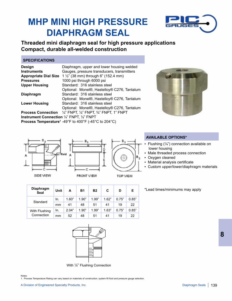
A Division of Engineered Specialty Products, Inc. 139
MHP MINI HIGH PRESSURE DIAPHRAGM SEAL
SPECIFICATIONS
Threaded mini diaphragm seal for high pressure applicationsCompact, durable all-welded construction
Design Diaphragm, upper and lower housing welded Instruments Gauges, pressure transducers, transmittersAppropriate Dial Size 1 ½” (38 mm) through 6” (152.4 mm)Pressures 1000 psi through 6000 psiUpper Housing Standard: 316 stainless steel Optional: Monel®, Hastelloy® C276, TantalumDiaphragm Standard: 316 stainless steel Optional: Monel®, Hastelloy® C276, TantalumLower Housing Standard: 316 stainless steel Optional: Monel®, Hastelloy® C276, TantalumProcess Connection ¼” FNPT, ½” FNPT, ¾” FNPT, 1” FNPTInstrument Connection ¼” FNPT, ½” FNPT Process Temperature1 -49°F to 400°F (-45°C to 204°C)
▪ Flushing (¼”) connection available on lower housing▪ Male threaded process connection▪ Oxygen cleaned▪ Material analysis certificate▪ Custom upper/lower/diaphragm materials
*Lead times/minimums may apply
AVAILABLE OPTIONS*
Diaphragm Seal Unit A B1 B2 C D E
StandardIn. 1.60” 1.90” 1.99” 1.62” 0.75” 0.85”mm 41 48 51 41 19 22
With Flushing Connection
In. 2.04” 1.90” 1.99” 1.63” 0.75” 0.85”mm 52 48 51 41 19 22
With ¼” Flushing Connection
8
Diaphragm Seals
Notes: 1. Process Temperature Rating can vary based on materials of construction, system fill fluid and pressure gauge selection.

140 A Division of Engineered Specialty Products, Inc.
MLP MINI LOW PRESSUREDIAPHRAGM SEAL
SPECIFICATIONS
Threaded mini diaphragm seal for low pressure applicationsCompact, durable all-welded construction
Design Diaphragm, upper and lower housing welded Instruments Gauges, pressure transducers, transmittersAppropriate Dial Size 1 ½” (38 mm) through 4 ½” (114.3 mm) Pressures Vacuum or pressures up to 2500 psiUpper Housing Standard: 316 stainless steel Optional: Monel®, Hastelloy® C276, TantalumDiaphragm Standard: 316 stainless steel Optional: Monel®, Hastelloy® C276, TantalumLower Housing Standard: 316 stainless steel Optional: Monel®, Hastelloy® C276, TantalumProcess Connection ¼” FNPT, ½” FNPT, ¾” FNPT, 1” FNPTInstrument Connection ¼” FNPT, ½” FNPT Process Temperature1 -49°F to 750°F (-45°C to 399°C)
▪ Flushing (¼”) connection available on lower housing▪ Male threaded process connection▪ Oxygen cleaned▪ Material analysis certificate▪ Custom upper/lower/diaphragm materials
*Lead times/minimums may applyDiaphragm Seal Unit A B1 B2 C D E F G
StandardIn. 1.51” 1.87” 1.74” 1.77” 0.50” 0.53” 0.48” 2.48”mm 38 47 44 45 13 13 12 63
With Flushing Connection
In. 1.84” 1.86” 1.70” 2.01” 0.50” 0.50” 0.82” 2.48mm 47 1.47 43 51 13 13 21 63
AVAILABLE OPTIONS*
With ¼” Flushing Connection
8
Diaphragm Seals
Notes: 1. Process Temperature Rating can vary based on materials of construction, system fill fluid and pressure gauge selection.

A Division of Engineered Specialty Products, Inc. 141
THREADED DIAPHRAGM SEAL PART NUMBERING SYSTEM
UPPER HOUSING
S = Carbon Steel J = 316 Stainless Steel
INSTRUMENT CONNECTION
1 = ¼” FNPT 2 = ½” FNPT
PROCESS CONNECTION
1 = ¼” FNPT 2 = ½” FNPT 3 = ¾” FNPT 4 = 1” FNPT X = Other
DIAPHRAGM MATERIAL LOWER HOUSING MATERIAL
S = Carbon Steel G = 304 Stainless Steel J = 316 Stainless Steel K = Tantalum M = Monel® T = PTFE (300 psi max) C = Carpenter 20® (Alloy 20) H = Hastelloy® C276 N = Titanium P = PTFE Coated 316 Stainless Steel X = Other
FLUSHING CONNECTION
F = Flushing (¼”) Connection
EXAMPLE: “DS-J2JJT2I-F”3
DS = Diaphragm Seal J = 316 Stainless Steel Upper Housing 2 = ½” FNPT Instrument Connection J = 316 Stainless Steel Diaphragm J = 316 Stainless Steel Lower Housing T = Threaded Connection 2 = ½” FNPT Process Connection I = 2500 psi (welded diaphragm)
F = Flushing (¼”) Connection
DS
CONNECTION TYPE
T = Threaded
SEAL/CONNECTION RATING
A-LP = Vacuum to 300 psi (clamped)1
I-LP = Vacuum to 300 psi (welded)2
A = (clamped)1
I = (welded)2
I-10K = 10,000 psi (welded)
8
Diaphragm Seals
Notes: 1. Metallic diaphragm rated up to 2000 psi2. Metallic diaphragm rated up to 2500 psi Elastomer diaphragm ratings vary, consult PIC Gauges for details. 3. Not all part numbers or options are available from stock. Consult PIC Gauges for availability.

142 A Division of Engineered Specialty Products, Inc.
THREADED DIAPHRAGM SEAL
SPECIFICATIONS
Threaded full size diaphragm seal Heavy duty, bolted construction
Design Standard: Diaphragm welded to upper housing Also available: ClampedInstruments Gauges, pressure switches, transmittersAppropriate Dial Size 2 ½” (63 mm) through 6” (152.4 mm) Pressures Vacuum or pressures up to 2500 psiUpper Housing Chrome plated carbon steel or stainless steelWetted Materials Standard: Carbon, 304 or 316 stainless steel (Diaphragm/ Also available: Hastelloy® C276, Monel®, Lower Housing) Tantalum, PTFE (clamped), Carpenter 20®, Titanium, Others upon request Process Connection ¼” FNPT, ½” FNPT, ¾” FNPT, 1” FNPTInstrument Connection ¼” FNPT, ½” FNPT Bolts Galvanized steel (CS upper) Stainless steel (SS upper)Gaskets Standard: Buna N® Also available: Viton®, PTFE, Grafoil®, others upon requestProcess Temperature1 -4°F to 212°F (-20°C to 100°C) ▪ Clamped diaphragm
▪ Flushing (¼”) connection available on lower housing▪ Male threaded process connection▪ Oxygen cleaned▪ Material analysis certificate▪ High temperature with grafoil gasket▪ Clean-out ring (available on clamped designs only)
*Lead times/minimums may apply
Diaphragm Seal Unit A B
StandardIn. 4.00” 1.50”mm 100 38
With Flushing Connection
In. 4.00” 1.75”mm 100 45
With Clean-out Ring
In. 4.00” 2.13”mm 100 54
AVAILABLE OPTIONS*
STANDARD WITH FLUSHING CONNECTION
WITH CLEAN-OUT RING
8
Diaphragm Seals
Notes: 1. Process Temperature Rating can vary based on materials of construction, system fill fluid, gaskets and pressure gauge selection.
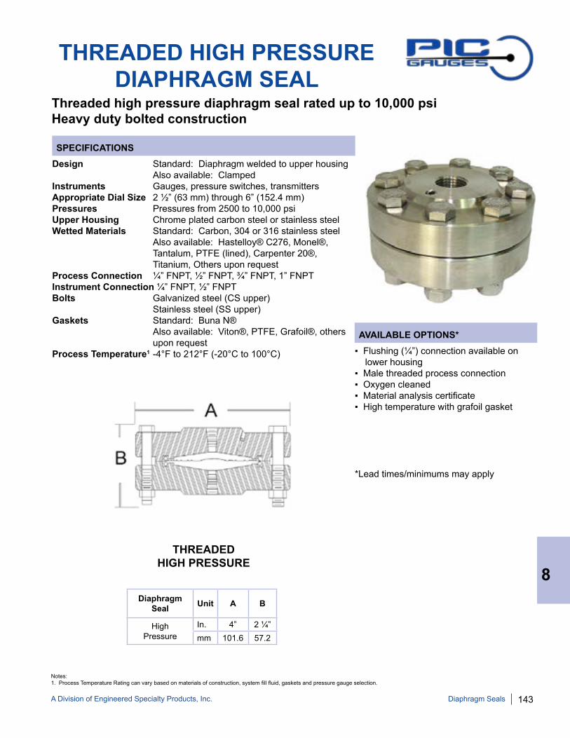
A Division of Engineered Specialty Products, Inc. 143
THREADED HIGH PRESSUREDIAPHRAGM SEAL
SPECIFICATIONS
Threaded high pressure diaphragm seal rated up to 10,000 psi Heavy duty bolted construction
Design Standard: Diaphragm welded to upper housing Also available: ClampedInstruments Gauges, pressure switches, transmittersAppropriate Dial Size 2 ½” (63 mm) through 6” (152.4 mm) Pressures Pressures from 2500 to 10,000 psiUpper Housing Chrome plated carbon steel or stainless steelWetted Materials Standard: Carbon, 304 or 316 stainless steel Also available: Hastelloy® C276, Monel®, Tantalum, PTFE (lined), Carpenter 20®, Titanium, Others upon request Process Connection ¼” FNPT, ½” FNPT, ¾” FNPT, 1” FNPTInstrument Connection ¼” FNPT, ½” FNPT Bolts Galvanized steel (CS upper) Stainless steel (SS upper)Gaskets Standard: Buna N® Also available: Viton®, PTFE, Grafoil®, others upon request Process Temperature1 -4°F to 212°F (-20°C to 100°C) ▪ Flushing (¼”) connection available on
lower housing▪ Male threaded process connection▪ Oxygen cleaned▪ Material analysis certificate▪ High temperature with grafoil gasket
*Lead times/minimums may apply
Diaphragm Seal Unit A B
High Pressure
In. 4” 2 ¼”mm 101.6 57.2
AVAILABLE OPTIONS*
THREADED HIGH PRESSURE
8
Diaphragm Seals
Notes: 1. Process Temperature Rating can vary based on materials of construction, system fill fluid, gaskets and pressure gauge selection.

144 A Division of Engineered Specialty Products, Inc.
THREADED LOW PRESSURE DIAPHRAGM SEAL
SPECIFICATIONS
Threaded diaphragm seal designed for sensitive, low pressure applications, Vacuum - 100 psi, including inches water column and mbar ranges
Design Standard: Diaphragm welded to upper housing Also available: ClampedInstruments Gauges, pressure switches, transmittersAppropriate Dial Size 2 ½” (63 mm) through 6” (152.4 mm) Pressures Vacuum or pressures up to 100 psiMaximum Pressure 1,000 psiUpper Housing Chrome plated carbon steel or stainless steelWetted Materials Standard: Carbon, 304 or 316 stainless steel Also available: Hastelloy® C276, Monel®, Tantalum, PTFE (clamped), Carpenter 20®, Titanium, Others upon request Process Connection ¼” FNPT, ½” FNPT, ¾” FNPT, 1” FNPTInstrument Connection ¼” FNPT, ½” FNPT Bolts Galvanized steel (CS upper) Stainless steel (SS upper)Gaskets Standard: Buna N® Also available: Viton®, PTFE, Grafoil®, others upon request Process Temperature1 -4°F to 212°F (-20°C to 100°C)
▪ Clamped diaphragm▪ Flushing (¼”) connection available on lower housing▪ Male threaded process connection▪ Oxygen cleaned▪ Material analysis certificate▪ High temperature with grafoil gasket
*Lead times/minimums may apply
Diaphragm Seal Unit A B
StandardIn. 5” 1 ½”mm 127 38
AVAILABLE OPTIONS*
LOW PRESSURE
8
Diaphragm Seals
Notes: 1. Process Temperature Rating can vary based on materials of construction, system fill fluid, gaskets and pressure gauge selection.

A Division of Engineered Specialty Products, Inc. 145
FLANGED DIAPHRAGM SEAL PART NUMBERING SYSTEM
UPPER HOUSING
S = Carbon Steel J = 316 Stainless Steel
INSTRUMENT CONNECTION
1 = ¼” FNPT 2 = ½” FNPT
PROCESS CONNECTION
2 = ½” FNPT 3 = ¾” FNPT 4 = 1” FNPT 6 = 1 ½” FNPT 8 = 2” FNPT 9 = 3” FNPT X = Other
DIAPHRAGM MATERIAL LOWER HOUSING MATERIAL
S = Carbon Steel G = 304 Stainless Steel J = 316 Stainless Steel K = Tantalum M = Monel® T = PTFE C = Carpenter 20® (Alloy 20) H = Hastelloy® C276 N = Titanium L = PTFE Lined 316 Stainless Steel P = PTFE Coated 316 Stainless Steel X = Other
FLUSHING CONNECTION
F = Flushing (¼”) Connection
EXAMPLE: “DS-J2JJF2F”2
DS = Diaphragm Seal J = 316 Stainless Steel Upper Housing 2 = ½” FNPT Instrument Connection J = 316 Stainless Steel Diaphragm J = 316 Stainless Steel Lower Housing F = RF Flanged Connection 2 = ½” Process Connection F = 300 #
DS
CONNECTION TYPE1
F = RF Flanged X = Other
FLANGE CLASS1
E = 150 # F = 300 # G = 600 # H = 900 # I = 1500 #
8
Diaphragm Seals
Notes: 1. Other connection types and flange classes available upon request. 2. Not all part numbers or options are available from stock. Consult PIC Gauges for availability.
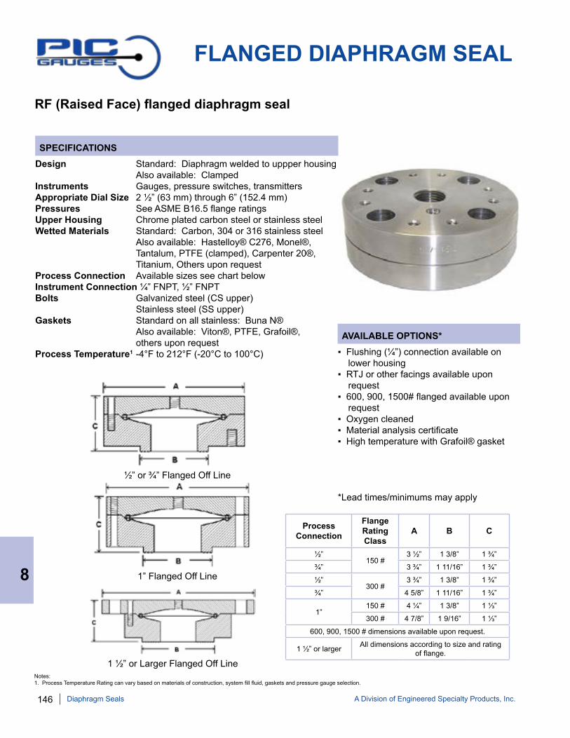
146 A Division of Engineered Specialty Products, Inc.
FLANGED DIAPHRAGM SEAL
SPECIFICATIONS
RF (Raised Face) flanged diaphragm seal
Design Standard: Diaphragm welded to uppper housing Also available: ClampedInstruments Gauges, pressure switches, transmittersAppropriate Dial Size 2 ½” (63 mm) through 6” (152.4 mm) Pressures See ASME B16.5 flange ratingsUpper Housing Chrome plated carbon steel or stainless steelWetted Materials Standard: Carbon, 304 or 316 stainless steel Also available: Hastelloy® C276, Monel®, Tantalum, PTFE (clamped), Carpenter 20®, Titanium, Others upon request Process Connection Available sizes see chart belowInstrument Connection ¼” FNPT, ½” FNPT Bolts Galvanized steel (CS upper) Stainless steel (SS upper)Gaskets Standard on all stainless: Buna N® Also available: Viton®, PTFE, Grafoil®, others upon request Process Temperature1 -4°F to 212°F (-20°C to 100°C) ▪ Flushing (¼”) connection available on
lower housing▪ RTJ or other facings available upon request▪ 600, 900, 1500# flanged available upon request▪ Oxygen cleaned▪ Material analysis certificate▪ High temperature with Grafoil® gasket
*Lead times/minimums may apply
AVAILABLE OPTIONS*
½” or ¾” Flanged Off Line
1” Flanged Off Line
1 ½” or Larger Flanged Off Line
8
Diaphragm Seals
Process Connection
Flange Rating Class
A B C
½” 150 #
3 ½” 1 3/8” 1 ¾”
¾” 3 ¾” 1 11/16” 1 ¾”
½” 300 #
3 ¾” 1 3/8” 1 ¾”
¾” 4 5/8” 1 11/16” 1 ¾”
1” 150 # 4 ¼” 1 3/8” 1 ⅓”
300 # 4 7/8” 1 9/16” 1 ⅓”
600, 900, 1500 # dimensions available upon request.
1 ½” or larger All dimensions according to size and rating of flange.
Notes: 1. Process Temperature Rating can vary based on materials of construction, system fill fluid, gaskets and pressure gauge selection.
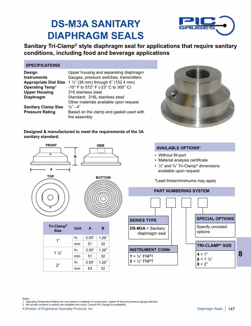
A Division of Engineered Specialty Products, Inc. 147
DS-M3A SANITARY DIAPHRAGM SEALS
Sanitary Tri-Clamp® style diaphragm seal for applications that require sanitary conditions, including food and beverage applications
SERIES TYPE
DS-M3A = Sanitary diaphragm seal
INSTRUMENT CONN 1 = ¼” FNPT 2 = ½” FNPT
TRI-CLAMP® SIZE
4 = 1” 6 = 1 ½” 8 = 2”
SPECIAL OPTIONS
Specify uncoded options
PART NUMBERING SYSTEM
SPECIFICATIONSDesign Upper housing and separating diaphragm Instruments Gauges, pressure switches, transmittersAppropriate Dial Size 1 ½” (38 mm) through 6” (152.4 mm) Operating Temp1 -10° F to 572° F (-23° C to 300° C)Upper Housing 316 stainless steelDiaphragm Standard: 316L stainless steel Other materials available upon requestSanitary Clamp Size ½” - 4” Pressure Rating Based on the clamp and gasket used with the assembly
Designed & manufactured to meet the requirements of the 3A sanitary standard.
▪ Without fill-port▪ Material analysis certificate▪ ½” and ¾” Tri-Clamp® dimensions available upon request
*Lead times/minimums may apply
AVAILABLE OPTIONS*
Tri-Clamp® Size Unit A B
1”In. 2.00” 1.26”mm 51 32
1 ½”In. 2.00” 1.26”mm 51 32
2”In. 2.50” 1.26”mm 63 32
8
Diaphragm Seals
Notes: 1. Operating Temperature Rating can vary based on materials of construction, system fill fluid and pressure gauge selection.2. Not all part numbers or options are available from stock. Consult PIC Gauges for availability.

148 A Division of Engineered Specialty Products, Inc.
PVC DIAPHRAGM SEAL
SPECIFICATIONS
PVC diaphragm seal for applications that are corrosive to metallic componentsDesigned for pressures up to 200 psi
Design PVC body with stainless steel bands to prevent splitting when installingInstruments Gauges, pressure switches, transmittersAppropriate Dial Size 2 ½” (63 mm) through 6” (152.4 mm) Pressures Vacuum up to 200 psiUpper Housing PVCDiaphragm PTFE or Viton®Lower Housing PVC Process Connection ¼” FNPT, ½” FNPTInstrument Connection ¼” FNPT, ½” FNPTBolts 304 Stainless SteelGaskets Integral to diaphragm (PTFE)
▪ Oxygen cleaned▪ Material analysis certificate
*Lead times/minimums may apply
Part Pcs. Materials
Lower Housing 1 PVC
Diaphragm 1 PTFE or Viton®
Upper Housing 1 PVC
Optional Gauge 1
Hex Bolt, Nut & Washers 9 sets 304SS,M5x30
Stainless Steel Bands 2 SS
AVAILABLE OPTIONS*
SERIES TYPE
DS-LPVC = PVC diaphragm seal
INSTRUMENT CONN 1 = ¼” FNPT 2 = ½” FNPT
PROCESS CONN
1 = ¼” FNPT 2 = ½” FNPT
SPECIAL OPTIONS
T = PTFE diaphragm V = Viton® diaphragm
PART NUMBERING SYSTEM
Process Conn Size
Instrument Conn Size A B C
1/4” 1/4” 3.22” 3.38” 1.29”
1/2” 1/2” 3.22” 3.38” 1.29”
Material 10-20°C 50-68°F
30°C 86°F
40°C 104°F
50°C 122°F
60°C 140°F
PVC working psi 150 115 85 60 15
Temperature Ranges - PVC: -10 to 60°C (14 to 140°F)
8
Diaphragm Seals
NOTE: Not all part numbers or options are available from stock. Consult PIC Gauges for availability.

A Division of Engineered Specialty Products, Inc. 149
701DDS MOLDED GAUGE & DIAPHRAGM SEAL PART NUMBERING SYSTEM
Dial Unit A B C D
2 ½”In. 3.16” 1.61” 5.35” 2.32”mm 80.5 41 136 59
Dial Range Figure Intervals
Graduation Intervals
0/15 psi 2 psi 0.2 psi
0/30 psi 5 psi 0.5 psi
0/60 psi 10 psi 1 psi
0/100 psi 20 psi 2 psi
0/160 psi 20 psi 2 psi
0/200 psi 40 psi 5 psi
8
Diaphragm Seals
SERIES TYPE
701DDS = Molded gauge and diaphragm seal dry/fillable 701LDS = Molded gauge and diaphragm seal glycerine filled
CASE/BODY/DIAPHRAGM
BLANK = Polypropylene with Viton® diaphragm seal T = PVDF with PTFE diaphragm seal
DIAL SIZE
25 = 2 ½”
PROCESS CONNECTION 2 = ½” FNPT 4 = ¼” FNPT
RANGE
B = 0/15 psi C = 0/30 psi D = 0/60 psi E = 0/100 psi F = 0/160 psi G = 0/200 psi
NOTE: Not all part numbers or options are available from stock. Consult PIC Gauges for availability.

150 A Division of Engineered Specialty Products, Inc.
SPECIFICATIONS - 701DDS-T PVDF CASE/PTFE SEAL
Dial Size 2 ½” (63 mm) Case Injection molded PVDF, dry yet fillableWetted Parts: Diaphragm PTFE Lower Housing PVDFBezel Injection molded PVDF, removableLens Polycarbonate Pointer Black aluminumScale Standard: psi/BAR x 100 = kPaPressure 0/15 to 0/200 psiAccuracy 2-1-2% of span, ASME B40.1 Grade A Maximum Temp -4° F to 140° F (-20° C to 60° C)Internals(non-wetted) 316 stainless steelProcess Connection ¼” FNPT or ½” FNPT System Fill Fluid Based on customer requirements
701DDS MOLDED GAUGE & DIAPHRAGM SEAL
SPECIFICATIONS - 701DDS POLYPROPYLENE CASE/VITON® SEAL
One-piece molded gauge/diaphragm seal assemblyHeavy duty, tamper-resistant design
Dial Size 2 ½” (63 mm) Case Injection molded polypropylene, dry yet fillableWetted Parts: Diaphragm Viton® Lower Housing Polypropylene Bezel Injection molded polypropylene, removableLens Polycarbonate Pointer Black aluminumScale Standard: psi/BAR x 100 = kPaPressure 0/15 to 0/200 psiAccuracy 2-1-2% of span, ASME B40.1 Grade A Maximum Temp -4° F to 140° F (-20° C to 60° C)Internals(non-wetted) Copper alloyProcess Connection ¼” FNPT or ½” FNPT System Fill Fluid Based on customer requirements
▪ Liquid Fill Options, see page 176
*Lead times/minimums may apply
AVAILABLE OPTIONS*
▪ Liquid Fill Options, see page 176
*Lead times/minimums may apply
AVAILABLE OPTIONS*
SPECIFY MOUNT FLUID WHEN ORDERING
SPECIFY MOUNT FLUID WHEN ORDERING
8
Diaphragm Seals
Design meets or exceeds ASME B40.100 pressure gauge standard.
Design meets or exceeds ASME B40.100 pressure gauge standard.

A Division of Engineered Specialty Products, Inc. 151
DIAPHRAGM SEAL FILL FLUID SPECIFICATIONS
NOTE 1: Not to be used in contact with aluminum or magnesium.
PIC Gauges offers a wide variety of fill fluids appropriate for numerous applications. When selecting fill fluids, consideration must be given to the following: 1. Below specifications are for fill fluid only. Maximum temperature ratings of instruments must be taken into consideration in conjunction with selection of fill fluid.
2. Physical properties of the fill fluid at the ambient and process temperature extremes of the application.
3. Chemical compatibility with the process fluid to avoid potentially hazardous reactions in the event of a bourdon tube or diaphragm failure.
4. For food processing applications, the fill fluid selected must be nontoxic.
5. For strong oxidizers, like oxygen, chlorine, hydrogen peroxide or nitric acid, use inert fill fluids, including Fluorolube FS-5® and Halocarbon®. DO NOT USE hydrocarbon based fluids, such as glycerine and silicone, as doing so may result in an explosive chemical reaction.
*Selection of fill fluid should only be made by customer taking into account all relevant details.
FILL FLUID TEMP RANGESPECIFIC GRAVITY AT TEMPERATURE
VISCOSITY AT TEMPERATURE
Glycerine 99.5% 30° to 300° F 1.26 77° F 1110 cSt 68° FSilicone DC-200 1000 cSt -50° to 450° F 0.96 77° F 1000cSt 76° FMineral Oil -30° to 200° F 0.85 59° F 57 cSt 68° FPropylene Glycol (pharmaceutical USP) -50° to 200° F 1.03 77° F 42.6 cSt 76° F
Halocarbon Oil®1 -40° to 400° F 1.87 100° F 6.3 cSt 76° F
Fluorolube FS-5®1 -40° to 500° F 1.87 100° F 5.5 cSt 76° F
Syltherm 800® -40° to 750° F 0.93 77° F 10.7 cSt 76° F
Neobee M-20® -4° to 320° F 0.92 77° F 9.5 cP 76° F
Ethylene Glycol (Anti-freeze) -30° to 300° F 1.10 80° F 30e 76° F
FILL FLUID APPLICATION PART NUMBER
Glycerine 99.5% Standard including Food & Beverage MOUNT-GLYSilicone DC-200 1000 cSt Low Temperature MOUNT-SILMineral Oil Food & Beverage MOUNT-MINERALPropylene Glycol (pharmaceutical USP) Low Temperature MOUNT-PROPYL
Halocarbon Oil®1 Oxygen & Chlorine Service MOUNT-HALO
Fluorolube FS-5®1 Oxygen & Chlorine Service MOUNT-FLUOR
Syltherm 800® High Temperature MOUNT-SYL
Neobee M-20® Food & Beverage MOUNT-NEOBEE M-20
Ethylene Glycol (Anti-freeze) Low Temperature MOUNT-GLYCOL
8
Diaphragm Seals

152 A Division of Engineered Specialty Products, Inc.
9
THERMOMETERS
Thermometers are used to measure temperature. PIC Gauges stocks a variety of temperature measuring instruments, including bimetals, magnetic thermometers, tridicators and scale thermometers.
VARIOUS BIMETALSPocket style, clip style, hot
water thermometer
BIMETAL ADJUSTABLE ANGLE
Every angle thermometer available in 3” and 5” dials
SURFACE Dual magnet mount surface
thermometer or spring held for pipe mount
INDUSTRIAL TRIDICATORS
Indicate both temperature and pressure
THERMOWELLSVarious sizes, connections and
materials
HEAVY DUTYTRIDICATORS
Indicate both temperature and pressure
9” SCALEAdjustable angle available in a
variety of stem lengths
SOLAR DIGITAL Powered with
bi-directional solar panels
5” SCALERed liquid filled (no mercury)
white painted steel scale
Thermometers & Thermowells
STANDARD BIMETAL90° back angle type available in
2”, 3” and 5” dials
BARBEQUE 3” dial BBQ pit thermometer
reads 50-550° F
REMOTE DIAL THERMOMETER
Vapor & gas actuated for direct, surface or panel mounting
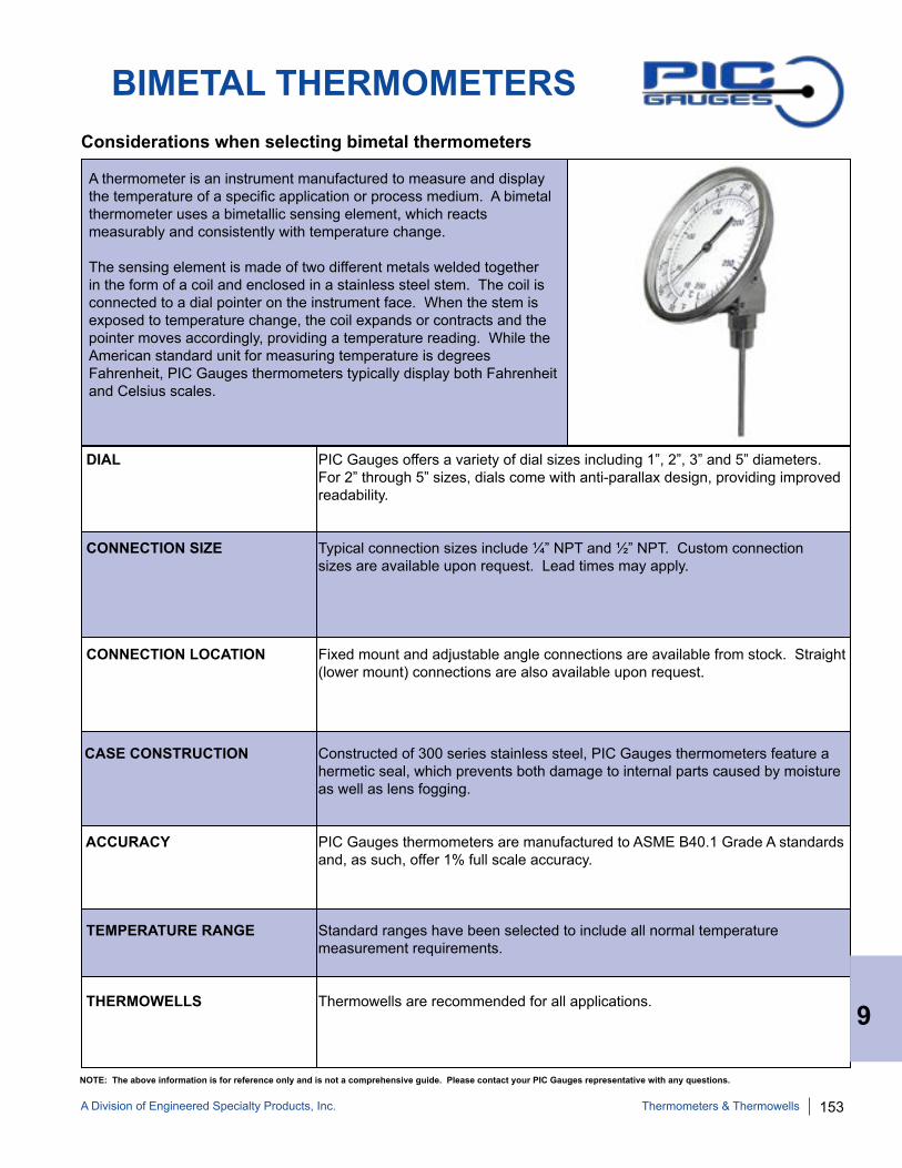
A Division of Engineered Specialty Products, Inc. 153
BIMETAL THERMOMETERS
A thermometer is an instrument manufactured to measure and display the temperature of a specific application or process medium. A bimetal thermometer uses a bimetallic sensing element, which reacts measurably and consistently with temperature change.
The sensing element is made of two different metals welded together in the form of a coil and enclosed in a stainless steel stem. The coil is connected to a dial pointer on the instrument face. When the stem is exposed to temperature change, the coil expands or contracts and the pointer moves accordingly, providing a temperature reading. While the American standard unit for measuring temperature is degrees Fahrenheit, PIC Gauges thermometers typically display both Fahrenheit and Celsius scales.
Considerations when selecting bimetal thermometers
NOTE: The above information is for reference only and is not a comprehensive guide. Please contact your PIC Gauges representative with any questions.
DIAL PIC Gauges offers a variety of dial sizes including 1”, 2”, 3” and 5” diameters. For 2” through 5” sizes, dials come with anti-parallax design, providing improved readability.
CONNECTION SIZE Typical connection sizes include ¼” NPT and ½” NPT. Custom connection sizes are available upon request. Lead times may apply.
CONNECTION LOCATION Fixed mount and adjustable angle connections are available from stock. Straight (lower mount) connections are also available upon request.
CASE CONSTRUCTION Constructed of 300 series stainless steel, PIC Gauges thermometers feature a hermetic seal, which prevents both damage to internal parts caused by moisture as well as lens fogging.
ACCURACY PIC Gauges thermometers are manufactured to ASME B40.1 Grade A standards and, as such, offer 1% full scale accuracy.
TEMPERATURE RANGE Standard ranges have been selected to include all normal temperature measurement requirements.
THERMOWELLS Thermowells are recommended for all applications. 9
Thermometers & Thermowells

154 A Division of Engineered Specialty Products, Inc.
BIMETAL THERMOMETER PART NUMBERING SYSTEM
SERIES TYPE
B = Bimetal thermometer
DIAL SIZE
1 = 1” Diameter 2 = 2” Diameter 3 = 3” Diameter 5 = 5” Diameter
CONNECTION TYPE
A = Adjustable angle B = Back angle S = Straight (lower mount) M = Magnetic
STEM LENGTH
2 = 2 ½” 4 = 4” 6 = 6” 8 = 8” 9 = 9” 10 = 10” 12 = 12” 15 = 15” 18 = 18” 24 = 24” XX = Custom Length
RANGE
AA = -40/120° F/-40/50° C BB = -40/160° F/-40/71° C DD = 25/125° F/-4/52° C EE = 0/150° F/-18/66° C GG = 0/200° F/-18/93° C HH = 0/220° F/-18/104° C II = 0/250° F/-18/121° C JJ = 20/240° F/-7/116° C MM = 50/300° F/10/149° C PP = 50/400° F/10/204° C QQ = 50/500° F/10/260° C RR = 50/550° F/10/288° C SS = 150/750° F/66/399° C TT = 200/1000° F/93/538° C U = 100/600° F
EXAMPLE: “B3B4-II”
B = Bimetal thermometer 3 = 3” diameter dial size B = Back angle connection type 4 = 4” stem length
II = 0/250° F/-18/121° CDial
RangeFigure
IntervalsGraduation Intervals
-40/120° F 20° F 2° F
-40/160° F 20° F 2° F
25/125° F 10° F 1° F
0/150° F 20° F 2° F
0/200° F 20° F 2° F
0/220° F 20° F 2° F
0/250° F 20° F 2° F
20/240° F 20° F 2° F
Dial Range
Figure Intervals
Graduation Intervals
50/300° F 50° F 2° F
50/400° F 50° F 5° F
50/500° F 50° F 5° F
50/550° F 50° F 5° F
150/750° F 100° F 10° F
200/1000° F 100° F 10° F
100/600° F 50° F 5° F
STANDARD DIAL CONFIGURATIONS
9
Thermometers & Thermowells
NOTE: Not all part numbers or options are available from stock. Consult PIC Gauges for availability.

A Division of Engineered Specialty Products, Inc. 155
SPECIFICATIONS
AVAILABLE OPTIONS*
APPROXIMATE SHIPPING WEIGHTS/BOX QUANTITIES
BIMETAL THERMOMETERSFIXED BACK MOUNT (90°)
Dial type bimetal thermometer Features anti-vibration design, anti-parallax dial, hermetically sealed case
Dial 2” (50 mm), 3” (76 mm), 5” (130 mm) Anti-parallax dial designCase Stainless steel, hermetically sealedStem 316 stainless steel, welded to connectionLens GlassPointer Black aluminum Connection Back mount (90°), fixed ¼” NPT on 2”, ½” NPT on 2”, 3” & 5”Scale Standard: dual scale F & CAccuracy 1% full scale per Grade A, ASME B40.3 Ambient Temp* -30° F to 180° F External Adjustment Zero reset screw on 3” & 5” dial
▪ Certificate of Accuracy, NIST traceable ▪ Custom Dial▪ Special Connection Size▪ Single Scale ▪ Special Ranges▪ Custom Lens Material
*Lead times/minimums may apply
Dial Unit A B C D E F
2” In. 2.30" Stem Length 0.25” 0.51” 0.39” ¼” or
½” NPTmm 58.4 Stem Length 6.45 12.9 10
3”In. 3.26” Stem Length 0.25” 0.80” 0.43” ½”
NPTmm 83 Stem Length 6.45 20 11
5” In. 5.28” Stem Length 0.25” 0.82” 0.43” ½”
NPTmm 134 Stem Length 6.45 22 11
Dial Size Est. Unit Weight
Box Qty
2” 0.20 lbs(0.10 kg)
upon request
3” 0.65 lbs(0.28 kg)
upon request
5” 1.15 lbs(0.52 kg)
upon request
*NOTE: High or low ambient temperatures may have adverse effect on accuracy. Consult PIC Gauges for instrument selection.
9
Thermometers & Thermowells
Design meets or exceeds ASME B40.3 thermometer standard.
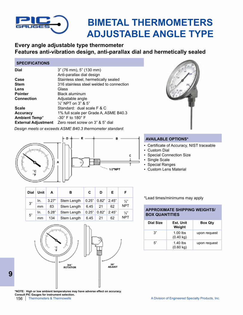
156 A Division of Engineered Specialty Products, Inc.
SPECIFICATIONS
AVAILABLE OPTIONS*
APPROXIMATE SHIPPING WEIGHTS/BOX QUANTITIES
BIMETAL THERMOMETERSADJUSTABLE ANGLE TYPE
Every angle adjustable type thermometerFeatures anti-vibration design, anti-parallax dial and hermetically sealed
Dial 3” (76 mm), 5” (130 mm) Anti-parallax dial designCase Stainless steel, hermetically sealedStem 316 stainless steel welded to connectionLens GlassPointer Black aluminum Connection Adjustable angle ½” NPT on 3” & 5”Scale Standard: dual scale F & CAccuracy 1% full scale per Grade A, ASME B40.3 Ambient Temp* -30° F to 180° F External Adjustment Zero reset screw on 3” & 5” dial
▪ Certificate of Accuracy, NIST traceable▪ Custom Dial▪ Special Connection Size▪ Single Scale ▪ Special Ranges▪ Custom Lens Material
*Lead times/minimums may applyDial Unit A B C D E F
3”In. 3.27” Stem Length 0.25” 0.82” 2.45” ½”
NPTmm 83 Stem Length 6.45 21 62
5” In. 5.28” Stem Length 0.25” 0.82” 2.45” ½”
NPTmm 134 Stem Length 6.45 21 62Dial Size Est. Unit
WeightBox Qty
3” 1.00 lbs(0.40 kg)
upon request
5” 1.40 lbs(0.60 kg)
upon request
9
Thermometers & Thermowells
Design meets or exceeds ASME B40.3 thermometer standard.
*NOTE: High or low ambient temperatures may have adverse effect on accuracy. Consult PIC Gauges for instrument selection.

A Division of Engineered Specialty Products, Inc. 157
SPECIFICATIONS - 1” DIAL SIZE POCKET THERMOMETER (B1B5)Dial Size 1” (25.4 mm)Case All stainless steel with plastic sleeve clip caseStem Length 5”Stem Construction 1/8” diameter pointed plain stem (non-threaded)Lens Magnifying plastic Pointer Red aluminumScale Standard: dual scale F & CTemperature Range -40/160° to 50/550° F & CAccuracy +/- 1.5% full scaleDesign meets or exceeds ASME B40.3 thermometer standard.
MISCELLANEOUS BIMETALS
SPECIFICATIONS - BARBEQUE GRILL THERMOMETER (BBQ-1)
Miscellaneous bimetals designed for specific applications
▪ Other stem lengths available upon request
*Lead times/minimums may apply
AVAILABLE OPTIONS*
▪ Other stem lengths available upon request▪ 2” dial size available upon request▪ Digital version available
*Lead times/minimums may apply
AVAILABLE OPTIONS*
Part Number Dial Unit A B C D E F
BBQ-1 3” In. 3.28" 2.5” 0.25” 0.82” 0.43” ½”
NPTmm 83 63 7 21 11
Dial Unit A B
1” In. 1.03” 0.51”
mm 26 13
9
Thermometers & Thermowells
Part Number Range
B1B5-BB -40/160°F / -40/71°C
B1B5-DD 25/125°F / -4/52°C
B1B5-HH 0/220°F / -18/104°C
B1B5-RR 50/550°F / 10/288°C
Dial Size 3” (76 mm) Anti-parallax dialCase All stainless steel constructionStem Length 2 ½”, 316 stainless welded at connectionConnection ½” NPTLens Heavy duty glass Pointer Black aluminumScale Standard: single scale F Temperature Range 50/550° F Accuracy 1% full scale External Adjustment Zero reset screw on case back Design meets or exceeds ASME B40.3 thermometer standard.

158 A Division of Engineered Specialty Products, Inc.
SPECIFICATIONS - HOT WATER THERMOMETER (B2B1-K-XX)
MISCELLANEOUS BIMETALS
SPECIFICATIONS - 2” CLIP STYLE THERMOMETER
Miscellaneous bimetals designed for specific applications
AVAILABLE OPTIONS*
▪ Other stem lengths available upon request▪ Other temperature ranges
*Lead times/minimums may apply
AVAILABLE OPTIONS*
▪ Other stem lengths available upon request
*Lead times/minimums may apply
Dial Size 2 ½” (63 mm) Case SteelStem Length 2” with Copper alloy thermowell or NPTBezel Stainless steelLens Plastic Pointer Black aluminumScale Standard: dual scale F & CTemperature Range 32/248° F & CAccuracy +/- 2% full scaleThermowell (included) ½” NPT Copper alloy threaded or solder typeDesign meets or exceeds ASME B40.3 thermometer standard.
Dial Unit A B C D
2” In. 2.52" 0.45” 1.71” 0.32”
mm 64 11 43 8
Dial Unit A B
2” In. 2.05" 0.41”
mm 52 10.5
Part NumbersB2B1-K-SW = Solder wellB2B1-K = ½” NPT
9
Thermometers & Thermowells
Part Number Stem Length
B2B6-R-CLIP 6”
B2B8-R-CLIP 8”
B2B12-R-CLIP 12”
Dial Size 2” (50 mm) Case All stainless steel with stainless steel clipStem Length 6”, 8”, 12”Lens Plastic Pointer Black aluminumScale Standard: single scale F Temperature Range 50/550° F Accuracy +/-1.5% full scalePart Number B2BX-R-CLIPDesign meets or exceeds ASME B40.3 thermometer standard.
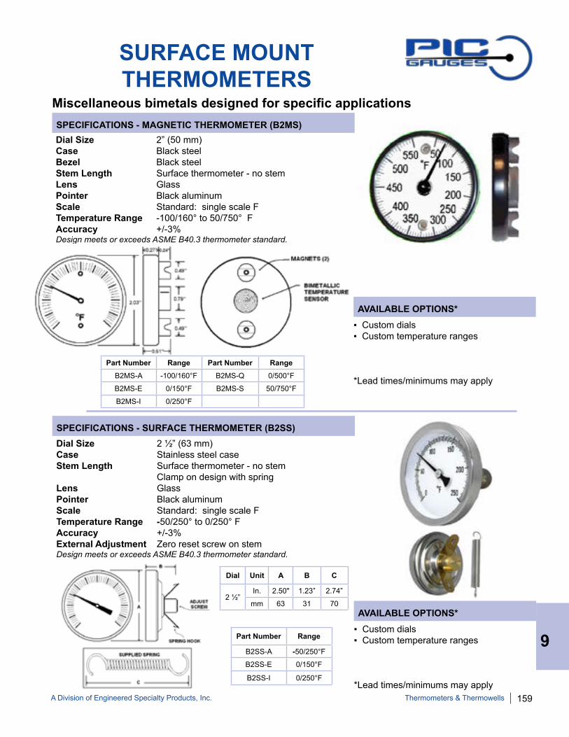
A Division of Engineered Specialty Products, Inc. 159
SPECIFICATIONS - SURFACE THERMOMETER (B2SS)Dial Size 2 ½” (63 mm) Case Stainless steel caseStem Length Surface thermometer - no stem Clamp on design with springLens Glass Pointer Black aluminumScale Standard: single scale F Temperature Range -50/250° to 0/250° F Accuracy +/-3%External Adjustment Zero reset screw on stemDesign meets or exceeds ASME B40.3 thermometer standard.
SURFACE MOUNTTHERMOMETERS
SPECIFICATIONS - MAGNETIC THERMOMETER (B2MS)
Miscellaneous bimetals designed for specific applications
Dial Size 2” (50 mm) Case Black steelBezel Black steelStem Length Surface thermometer - no stemLens Glass Pointer Black aluminumScale Standard: single scale F Temperature Range -100/160° to 50/750° FAccuracy +/-3%Design meets or exceeds ASME B40.3 thermometer standard.
▪ Custom dials ▪ Custom temperature ranges
*Lead times/minimums may apply
AVAILABLE OPTIONS*
▪ Custom dials▪ Custom temperature ranges
*Lead times/minimums may apply
AVAILABLE OPTIONS*
Dial Unit A B C
2 ½”In. 2.50" 1.23” 2.74”
mm 63 31 70
9
Thermometers & Thermowells
Part Number Range
B2SS-A -50/250°F
B2SS-E 0/150°F
B2SS-I 0/250°F
Part Number Range Part Number RangeB2MS-A -100/160°F B2MS-Q 0/500°F
B2MS-E 0/150°F B2MS-S 50/750°F
B2MS-I 0/250°F

160 A Division of Engineered Specialty Products, Inc.
THERMOWELLSPIC Gauges offers a complete line of thermowells, manufacturing all sizes, connec-tions and materials, in addition to stocking the most commonly used types.
LAGGING WELLSSTANDARD WELLS
MATERIALSBrass
Carbon Steel
304 Stainless Steel
316 Stainless Steel
Monel®
Hastelloy® C276
Titanium
Tantalum
Ceramic
PROCESS CONNECTIONSThreaded
Flanged
Welded
Clamped
Sanitary
Van Stone
SPECIAL APPLICATIONSHigh Pressure
High Velocity
Sanitary
Test Port
OPTIONS*
RTJ FLANGEDANSI FLANGED
SOCKET WELDWELD-IN TEST PORTVAN STONE
*Others available upon request.
9
Thermometers & Thermowells
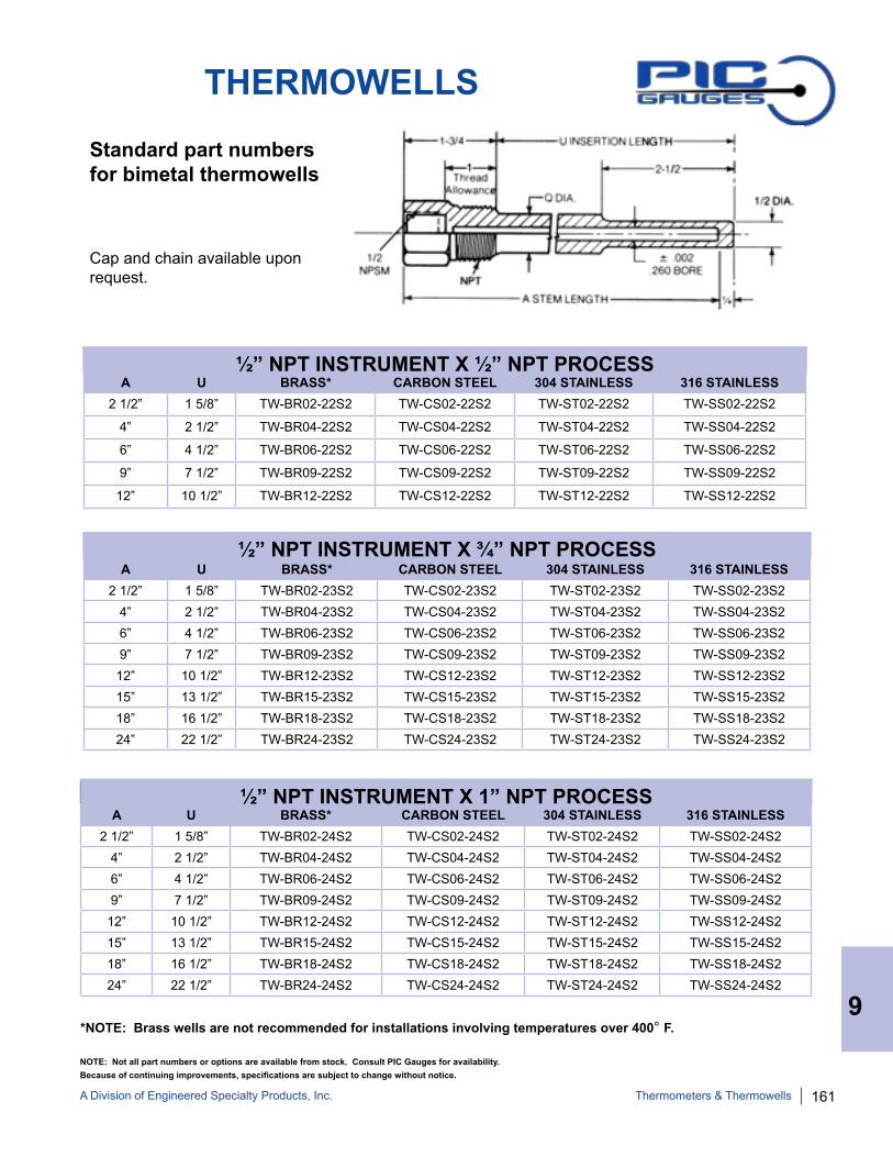
A Division of Engineered Specialty Products, Inc. 161
A U BRASS* CARBON STEEL 304 STAINLESS 316 STAINLESS2 1/2” 1 5/8” TW-BR02-22S2 TW-CS02-22S2 TW-ST02-22S2 TW-SS02-22S2
4” 2 1/2” TW-BR04-22S2 TW-CS04-22S2 TW-ST04-22S2 TW-SS04-22S2
6” 4 1/2” TW-BR06-22S2 TW-CS06-22S2 TW-ST06-22S2 TW-SS06-22S2
9” 7 1/2” TW-BR09-22S2 TW-CS09-22S2 TW-ST09-22S2 TW-SS09-22S2
12” 10 1/2” TW-BR12-22S2 TW-CS12-22S2 TW-ST12-22S2 TW-SS12-22S2
A U BRASS* CARBON STEEL 304 STAINLESS 316 STAINLESS2 1/2” 1 5/8” TW-BR02-23S2 TW-CS02-23S2 TW-ST02-23S2 TW-SS02-23S2
4” 2 1/2” TW-BR04-23S2 TW-CS04-23S2 TW-ST04-23S2 TW-SS04-23S26” 4 1/2” TW-BR06-23S2 TW-CS06-23S2 TW-ST06-23S2 TW-SS06-23S29” 7 1/2” TW-BR09-23S2 TW-CS09-23S2 TW-ST09-23S2 TW-SS09-23S212” 10 1/2” TW-BR12-23S2 TW-CS12-23S2 TW-ST12-23S2 TW-SS12-23S215” 13 1/2” TW-BR15-23S2 TW-CS15-23S2 TW-ST15-23S2 TW-SS15-23S218” 16 1/2” TW-BR18-23S2 TW-CS18-23S2 TW-ST18-23S2 TW-SS18-23S224” 22 1/2” TW-BR24-23S2 TW-CS24-23S2 TW-ST24-23S2 TW-SS24-23S2
A U BRASS* CARBON STEEL 304 STAINLESS 316 STAINLESS2 1/2” 1 5/8” TW-BR02-24S2 TW-CS02-24S2 TW-ST02-24S2 TW-SS02-24S2
4” 2 1/2” TW-BR04-24S2 TW-CS04-24S2 TW-ST04-24S2 TW-SS04-24S26” 4 1/2” TW-BR06-24S2 TW-CS06-24S2 TW-ST06-24S2 TW-SS06-24S29” 7 1/2” TW-BR09-24S2 TW-CS09-24S2 TW-ST09-24S2 TW-SS09-24S212” 10 1/2” TW-BR12-24S2 TW-CS12-24S2 TW-ST12-24S2 TW-SS12-24S215” 13 1/2” TW-BR15-24S2 TW-CS15-24S2 TW-ST15-24S2 TW-SS15-24S218” 16 1/2” TW-BR18-24S2 TW-CS18-24S2 TW-ST18-24S2 TW-SS18-24S224” 22 1/2” TW-BR24-24S2 TW-CS24-24S2 TW-ST24-24S2 TW-SS24-24S2
THERMOWELLS
Standard part numbers for bimetal thermowells
Cap and chain available upon request.
½” NPT INSTRUMENT X ½” NPT PROCESS
½” NPT INSTRUMENT X ¾” NPT PROCESS
½” NPT INSTRUMENT X 1” NPT PROCESS
*NOTE: Brass wells are not recommended for installations involving temperatures over 400° F.9
Thermometers & Thermowells
Because of continuing improvements, specifications are subject to change without notice. NOTE: Not all part numbers or options are available from stock. Consult PIC Gauges for availability.

162 A Division of Engineered Specialty Products, Inc.
THERMOWELLS
Part numbers for bimetal thermowells with lagging extensions
Cap and chain available upon request.
*NOTE: Brass wells are not recommended for installations involving temperatures over 400° F.
A U T BRASS* CARBON STEEL 304 STAINLESS 316 STAINLESS4” 1 5/8” 1” TW-BR04-22L2 TW-CS04-22L2 TW-ST04-22L2 TW-SS04-22L26” 2 ½” 2” TW-BR06-22L2 TW-CS06-22L2 TW-ST06-22L2 TW-SS06-22L29” 4 ½” 3” TW-BR09-22L2 TW-CS09-22L2 TW-ST09-22L2 TW-SS09-22L212” 7 ½” 3” TW-BR12-22L2 TW-CS12-22L2 TW-ST12-22L2 TW-SS12-22L2
A U T BRASS* CARBON STEEL 304 STAINLESS 316 STAINLESS4” 1 5/8” 1” TW-BR04-23L2 TW-CS04-23L2 TW-ST04-23L2 TW-SS04-23L26” 2 ½” 2” TW-BR06-23L2 TW-CS06-23L2 TW-ST06-23L2 TW-SS06-23L29” 4 ½” 3” TW-BR09-23L2 TW-CS09-23L2 TW-ST09-23L2 TW-SS09-23L212” 7 ½” 3” TW-BR12-23L2 TW-CS12-23L2 TW-ST12-23L2 TW-SS12-23L215” 10 ½” 3” TW-BR15-23L2 TW-CS15-23L2 TW-ST15-23L2 TW-SS15-23L218” 13 ½” 3” TW-BR18-23L2 TW-CS18-23L2 TW-ST18-23L2 TW-SS18-23L224” 19 ½” 3” TW-BR24-23L2 TW-CS24-23L2 TW-ST24-23L2 TW-SS24-23L2
A U T BRASS* CARBON STEEL 304 STAINLESS 316 STAINLESS4” 1 5/8” 1” TW-BR04-24L2 TW-CS04-24L2 TW-ST04-24L2 TW-SS04-24L26” 2 ½” 2” TW-BR06-24L2 TW-CS06-24L2 TW-ST06-24L2 TW-SS06-24L29” 4 ½” 3” TW-BR09-24L2 TW-CS09-24L2 TW-ST09-24L2 TW-SS09-24L212” 7 ½” 3” TW-BR12-24L2 TW-CS12-24L2 TW-ST12-24L2 TW-SS12-24L215” 10 ½” 3” TW-BR15-24L2 TW-CS15-24L2 TW-ST15-24L2 TW-SS15-24L218” 13 ½” 3” TW-BR18-24L2 TW-CS18-24L2 TW-ST18-24L2 TW-SS18-24L224” 19½” 3” TW-BR24-24L2 TW-CS24-24L2 TW-ST24-24L2 TW-SS24-24L2
½” NPT INSTRUMENT X ½” NPT PROCESS
½” NPT INSTRUMENT X ¾” NPT PROCESS
½” NPT INSTRUMENT X 1” NPT PROCESS
9
Thermometers & Thermowells
NOTE: Not all part numbers or options are available from stock. Consult PIC Gauges for availability.

A Division of Engineered Specialty Products, Inc. 163
THERMOWELLPART NUMBERING SYSTEM
MATERIAL OF CONSTRUCTION
BR = Brass CS = Carbon Steel ST = 304 SS SS = 316 SS SL = 316 L SS XX = Special
STEM LENGTH
(Overall Thermowell Length - ¼”) 02 = 2 ½” 04 = 4” 06 = 6” 09 = 9” 12 = 12” XX = Special (specify length)
INSTRUMENT CONNECTION
Female Thread 1 = ¼” FNPT 2 = ½” FNPT X = Special (specify thread size)
STYLE
S = Stepped (standard) E = Straight L = Lagging T = Tapered
PROCESS CONNECTION
2 = ½” NPT 3 = ¾” NPT 4 = 1” NPT 5 = 1 ¼” NPT 6 = 1 ½” NPT 7 = 2” NPT 8 = 2 ½” NPT 9 = 3” NPT X = Special (specify thread size)
BORE DIAMETER
2= 0.260” 3 = 0.385” 5 = 0.500”
INSERTION (U DIMENSION)
04.5 = 4 ½” 11.5 = 11 ½” 20.5 = 20 ½”
FLANGE PRESSURE RATING 0 = No Flange 1= 150 psi 3 = 300 psi 6 = 600 psi 9 = 900 psi 5 = 1500 psi
FLANGE TYPE
RF = Raised face FF = Flat face RJ = Ring type joint VS = Van stone SW = Socket weld
TW .
9
Thermometers & Thermowells
EXAMPLE: “TW-SS12-26T2-10.03RF”
TW = Thermowell SS = 316 SS 12 = 12” stem 2 = ½” FNPT instrument connection 6 = 1 ½” NPT process connection T = Tapered 2 = 0.260” Bore Diameter 10.0 = 10” insertion 3 = 300 psi flange rating RF = Raised face flange
NOTE: Not all part numbers or options are available from stock. Consult PIC Gauges for availability.

164 A Division of Engineered Specialty Products, Inc.
PRESSURE - TEMPERATURE RATING - PSITemperature - °F
Material 70° 200° 400° 600° 800° 1000° 1200°Brass 5000 4200 1000 - - - -Carbon Steel 5200 5000 4800 4600 3500 1500 -304SS 7000 6200 5600 5400 5200 4500 1650316SS 7000 7000 6400 6200 6100 5100 2500Monel® 6500 6000 5400 5300 5200 1500 -
MAXIMUM FLUID VELOCITY - FEET PER SECONDInsertion Length - “U”
Well Type
Material 2 ½” 4 ½” 7 ½” 10 ½” 13 ½” 16 ½” 19 ½” 22 ½”
½” Standard and Lagging
Brass 207 75.5 27.3 13.9 8.4 5.6 4.1 3(59.3) (32.2) (19.7)
Carbon Steel
290 105 38 19.4 11.8 7.8 5.7 4.2(106) (59) (36.3)
304SS/ 316SS
300 109 39.5 20.1 12.2 8.1 5.9 4.4(148) (82.2)
Monel® 261 95 34.4 17.5 10.5 7.1 5.2 3.8(118) (65.5)
¾” Standard and Lagging
Brass 207 89.1 32.2 16.4 9.9 6.6 4.8 3.6(59.3) (39.8) (23.9)
Carbon Steel
290 123 44.9 22.8 13.8 9.3 6.7 4.9(106) (71.2) (42.7)
304SS/ 316SS
300 128 46.4 23.6 14.3 9.6 6.9 5.1(148) (99.3)
Monel® 261 112 40.6 20.7 12.4 8.3 6.1 4.5(118) (79.8)
1” Standard and Lagging
Brass 207 102 37 18.8 11.4 7.6 5.5 4.1(59.3) (47.6) (28)
Carbon Steel
290 143 51.6 26.2 15.9 10.6 7.6 5.7(106) (84.3) (50.6)
304SS/ 316SS
300 148 53.5 27.2 16.5 11 7.9 5.9(148) (117)
Monel® 261 128 46.7 23.7 14.4 9.5 6.9 5.1(118) (93.3)
NOTE: Values listed above are for steam, air, gas and similar density. Values shown in parentheses are for water flow only.
THERMOWELLTECHNICAL DATA
NOTE: PIC Gauges’ data on thermowell performance is based on industry standards in common use by design engi-neers and other manufacturers. PIC Gauges is not responsible for errors resulting from omission, transmission, transpo-sition, printing or interpretation of such data.
9
Thermometers & Thermowells

A Division of Engineered Specialty Products, Inc. 165
SPECIFICATIONS - GAS ACTUATED THERMOMETERDial Size 4 ½” (125 mm), 6” (150 mm) Case PhenolicCapillary Length CustomLens Plastic Pointer Black aluminum, slotted adjustableScale Standard: dual scale °F & °CTemperature Range CustomAccuracy 1% full scaleBulb 6” stainless steel with ½” NPT bushing
REMOTE DIAL & GAS ACTUATED THERMOMETERS
SPECIFICATIONS - REMOTE DIAL VAPOR THERMOMETER
Miscellaneous thermometers designed for specific applications
Dial Size 3 ½” (88.9 mm) Case Stainless steelCapillary Length 5 feetLens Polycarbonate Pointer Black aluminumScale Standard: dual scale °F & °CTemperature Range Custom, Stock - see chart belowAccuracy 1% full scale Box Quantity 30 piecesBulb 3” stainless steel plain bulb
▪ Other capillary lengths available upon request▪ Other ranges available upon request▪ Other dial sizes available upon request
*Lead times/minimums may apply
AVAILABLE OPTIONS*
▪ Other stem lengths available upon request
*Lead times/minimums may apply
AVAILABLE OPTIONS*
9
Thermometers & Thermowells
CUSTOM ORDER ITEM
Contact PIC Gauges for available options, part numbers, and
applicable lead times
CUSTOM ORDER ITEM
Contact PIC Gauges for available options, part
numbers, and applicable lead times
Stock Part Numbers Range Mounting
V35WFF-180 0/180°F Front Flange
V35WFF-250 0/250°F Front Flange
V35UCC-240 30/240°F U-Clamp
V35WFF-300 0/300°F Front Flange
V35WFF-550 50/550°F Front Flange

166 A Division of Engineered Specialty Products, Inc.
TRIDICATORS
Measure pressure and temperature in one instrumentAvailable in various sizes and configurations
INDUSTRIAL - ROUND3” TRIDICATOR
INDUSTRIAL - SQUARE HEAVY DUTY
9
Thermometers & Thermowells

A Division of Engineered Specialty Products, Inc. 167
SPECIFICATIONS
AVAILABLE OPTIONS*
APPROXIMATE SHIPPING WEIGHTS/BOX QUANTITIES
2 ½” TRIDICATORS
Dual reading pressure and temperature instrumentHigh quality, economical design for use in commercial and industrial boiler applications
Dial 2 ½” (63 mm)Case Black painted steel, dry non-fillableStem 1.75”, 2.95” or 3.63”, copper alloyLens Plastic with red indicatorPointer Black aluminum Connection Center back mount ¼” NPT, copper alloyScale Pressure: dual scale psi & ft of water column Temperature: dual scale F & CTemperature Range 70/320° F & 20/160° CAccuracy 3-2-3% full scale per Grade B, ASME B40.1 Ambient Temp* -30° F to 180° F
▪ Custom Dial▪ Special Connection Size▪ Single Scale ▪ Special Ranges▪ Custom Lens Material▪ Custom Stem Length▪ Custom Lagging Dimension▪ Stainless Steel Wetted Parts
*Lead times/minimums may applyDial Unit Stem Length A B C D E F
2 ½” In. 1.75” 2.64” 1.02” 0.77” 0.96” 0.31” 0.54”mm 44.5 67 26 20 25 8 13.6
2 ½” In. 2.95” 2.64” 1.02” 2.00” 0.96” 0.31” 0.54”mm 75 67 26 51 25 8 13.6
2 ½” In. 3.63” 2.64” 1.02” 2.00” 1.60” 0.31” 0.54”mm 92.2 67 26 51 41 8 13.6
PART NUMBER DIAL SIZE
PRESSURE TEMPERATUREpsi Ft of Water F C
TRI-RC-254Rx.xx-D 2 1/2” 0/75 0/170 70-320° 20-160°
TRI-RC-254Rx.xx-G 2 1/2” 0/200 0/460 70-320° 20-160°
Other ranges available upon request.
Stem Length
Est. Unit Weight
Box Qty
1.75” 0.30 lbs(0.14 kg)
100
2.95” 0.35 lbs(0.16 kg)
50
3.63” 0.35 lbs(0.16 kg)
50
*NOTE: High or low ambient temperatures may have adverse effect on accuracy. Consult PIC Gauges for instrument selection.
9
Thermometers & Thermowells

168 A Division of Engineered Specialty Products, Inc.
SPECIFICATIONS
AVAILABLE OPTIONS*
APPROXIMATE SHIPPING WEIGHTS/BOX QUANTITIES
PART NUMBER DIAL SIZE
PRESSURE TEMPERATUREpsi Ft of Water F C
TRI-RC-3.25R-3.00-D 3 1/4” 0/75 0/170 70-320° 20-160°
TRI-RC-3.25R-3.00-E 3 1/4” 0/100 0/230 70-320° 20-160°
TRI-RC-3.25R-3.00-G 3 1/4” 0/200 0/450 70-320° 20-160°
TRI-RC-3.25R-3.00-H 3 1/4” 0/300 0/700 70-320° 20-160°
Dual reading pressure and temperature instrumentHigh quality, economical design for use in commercial and industrial boiler applications
Dial Size Est. Unit Weight
Box Qty
3 ¼” 0.55 lbs(0.26 kg)
50
▪ Custom Dial▪ Special Connection Size▪ Single Scale ▪ Special Ranges▪ Custom Lens Material▪ Custom Stem Length▪ Custom Lagging Dimension▪ 316 Stainless Steel Wetted Parts
*Lead times may apply
Dial Unit A B C D E
3 ¼” In. 3.31” 1.23” 1.36” 2.23” 0.36”
mm 84 31 34.4 57 9.3
Dial 3 ¼” (83 mm)Case Black painted steel, dry non-fillableStem 3”, copper alloyLens Plastic with red indicatorPointer Black aluminum Connection Center back mount ½” NPT, copper alloyScale Pressure: dual scale psi & ft of water column Temperature: dual scale °F & °CTemperature Range 70/320° F & 20/160° CAccuracy 3-2-3% full scale per Grade B, ASME B40.1 Ambient Temp* -30° F to 180° F
3” TRIDICATORS
*NOTE: High or low ambient temperatures may have adverse effect on accuracy. Consult PIC Gauges for instrument selection.
9
Thermometers & Thermowells

A Division of Engineered Specialty Products, Inc. 169
SPECIFICATIONS
AVAILABLE OPTIONS*
APPROXIMATE SHIPPING WEIGHTS/BOX QUANTITIES
4” INDUSTRIAL TRIDICATORS
Dual reading pressure and temperature instrumentHigh quality, economical design for use in commercial and industrial boiler applications
Dial 4” (101 mm)Case Painted steel, dry non-fillableStem 2”, copper alloyLens Round: plastic Square: glassPointer Black aluminum Connection Lower mount, lower back mount ½” NPT, copper alloyScale Pressure: dual scale psi & kPa Temperature: dual scale °F & °CTemperature Range 70/320° F & 20/160° CAccuracy 1% full scale per Grade 1A, ASME B40.1 Ambient Temp* -30° F to 180° F
▪ Custom Dial▪ Special Connection Size▪ Single Scale ▪ Special Ranges▪ Custom Lens Material▪ Custom Stem Lengths
*Lead times/minimums may apply
Dial Unit A B C D
RoundIn. 4.23” 1.45” 0.51” 2.12”mm 107 37 13 54
SquareIn. 3.65” 1.47” 0.83” 2.00”
mm 93 37 21 51
PART NUMBER PRESSURE TEMPERATURE CONNECTION DIALTRI-RC-402L-D 0/75 psi 60-260° F lower round
TRI-RC-402L-G 0/200 psi 70-320° F lower round
TRI-RC-402L-H 0/300 psi 60-260° F lower round
TRI-RC-402R-D 0/75 psi 60-260° F back round
TRI-RC-402R-G 0/200 psi 70-320° F back round
TRI-SQ-402L-D 0/75 psi 60-260° F lower square
TRI-SQ-402L-E 0/100 psi 60-260° F lower square
TRI-SQ-402L-G 0/200 psi 80-320° F lower square
TRI-SQ-402R-D 0/75 psi 60-260° F back square
TRI-SQ-402R-E 0/100 psi 60-260° F back square
TRI-SQ-402R-G 0/200 psi 80-320° F back square
TRI-SQ-402R-H 0/300 psi 80-320° F back square
Round Dial Square Dial
Dial Size Est. Unit Weight
Box Qty
Round 0.95 lbs(0.40 kg)
50
Square 0.95 lbs(0.44 kg)
50
*NOTE: High or low ambient temperatures may have adverse effect on accuracy. Consult PIC Gauges for instrument selection.
9
Thermometers & Thermowells

170 A Division of Engineered Specialty Products, Inc.
SPECIFICATIONS
AVAILABLE OPTIONS*
APPROXIMATE SHIPPING WEIGHTS/BOX QUANTITIES
3” HEAVY DUTY TRIDICATORS
Dual reading pressure and temperature instrumentHigh quality, economical design for use in commercial and industrial boiler applications
Dial 3” (76.2 mm)Case Heavy duty, dry non-fillableStem 2”, copper alloyLens GlassPointer Black aluminum Connection Lower mount Center back mount ½” NPT, copper alloyScale Pressure: dual scale psi & feet of water Temperature: dual scale °F & °CTemperature Range 70/320° F & 20/160° CAccuracy 3-2-3% full scale per Grade B, ASME B40.1 Ambient Temp* -30° F to 180° F
▪ Custom Dial▪ Special Connection Size▪ Single Scale ▪ Special Ranges▪ Custom Lens Material▪ 316 Stainless Steel Wetted Parts
*Lead times/minimums may apply
Dial Unit A B C D
3” In. 3.21” 1.29” 0.32” 2.00”mm 81.5 33 8 51 Dial Size Est. Unit
WeightBox Qty
3” 0.70 lbs(0.32 kg)
50
*NOTE: High or low ambient temperatures may have adverse effect on accuracy. Consult PIC Gauges for instrument selection.
9
Thermometers & Thermowells
PART NUMBER CONNECTION DIAL SIZE
PRESSURE TEMPERATUREpsi Ft of Water F C
TRI-HD-302L-E Lower 3” 0/100 0/230 70-320° 20-160°
TRI-HD-302L-G Lower 3” 0/200 0/450 70-320° 20-160°
TRI-HD-302R-E Center Back 3” 0/100 0/230 70-320° 20-160°
TRI-HD-302R-G Center Back 3” 0/200 0/450 70-320° 20-160°

A Division of Engineered Specialty Products, Inc. 171
SPECIFICATIONS
AVAILABLE OPTIONS*
APPROXIMATE SHIPPING WEIGHTS/BOX QUANTITIES
INDUSTRIAL THERMOMETER
Blue spirit filled adjustable angle thermometer for industrial applications
Scale Size 7” (177.8 mm), 9” (228.6 mm)Case Black molded ABS for temps up to 200° F Black enamel die cast aluminum for ranges above 200° FStem 3 ½”, 6”, 9”, 12”, copper alloy Lens GlassIndicator Blue spirit Connection Lower mount, adjustable angle 1 ¼” -18” NEF threadScale Dual scale °F & °CTemperature Range 0-120° F, 30-240° F, Others available from stockAccuracy 1% scale division per Grade A, ASME B40.3
▪ Straight connection▪ 90° back angle connection▪ Plastic face at additional charge ▪ Thermowells▪ Cap and Lanyard▪ Aluminum Case
*Lead times/minimums may apply
SCALE SIZE
PART NUMBERSSTEM LENGTHS
3 ½” 6” 9” 12”
7” AS5H7 AS5L7 N/A N/A
9” AS5H9 AS5L9 AS5N9 AS5Q9
Part Number
Est. Unit Weight
Box Qty
AS5H7 1.00 lbs(0.46 kg)
upon request
AS5L7 1.10 lbs(0.50 kg)
upon request
AS5H9 1.15 lbs(0.52 kg)
upon request
AS5L9 1.20 lbs(0.56 kg)
upon request
AS5N9 1.35 lbs(0.62 kg)
upon request
AS5Q9 1.55 lbs(0.70 kg)
upon request
Scale Unit A B C D
7”In. 9.79" 2.41” 1.67” Stem
mm 249 62 43 Stem
Scale Unit E F G
7”In 0.44” 1.06” 1.25”
mm 11 27 32
Scale Unit A B C D
9”In. 11.9" 2.41” 1.67” Stem
mm 301 62 43 Stem
Scale Unit E F G
9”In 0.44” 1.06” 1.25”
mm 11 27 32
9
Thermometers & Thermowells
INDUSTRIAL THERMOWELL PART NUMBERS
Stem ProcessConnection Type Brass 304 SS 316 SS
3 ½” ¾” NPTStandard TWB-35 T6E3D2 T4E3D2
Lagging TWB-35-LAG T6E3D2B T4E3D2B
6” ¾” NPTStandard T1M3D2 T6M3D2 T4M3D2
Lagging T1M3D2E T6M3D2E T4M3D2E
Optional Cap and Lanyard
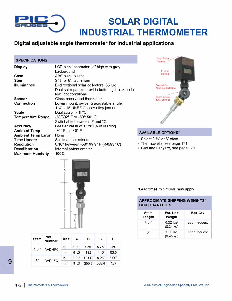
172 A Division of Engineered Specialty Products, Inc.
SPECIFICATIONS
AVAILABLE OPTIONS*
APPROXIMATE SHIPPING WEIGHTS/BOX QUANTITIES
SOLAR DIGITAL INDUSTRIAL THERMOMETER
Digital adjustable angle thermometer for industrial applications
Display LCD black character, ½” high with gray backgroundCase ABS black plasticStem 3 ½” or 6”, aluminumIlluminance Bi-directional solar collectors, 35 lux Dual solar panels provide better light pick up in low light conditionsSensor Glass passivated thermistorConnection Lower mount, swivel & adjustable angle 1 ¼” - 18 UNEF Copper alloy jam nutScale Dual scale °F & °CTemperature Range -58/302° F or -50/150° C Switchable between °F and °CAccuracy Greater value of 1° or 1% of reading Ambient Temp -30° F to 140° F Ambient Temp Error NoneTime Update Six times per minuteResolution 0.10° between -58/199.9° F (-50/93° C)Recalibration Internal potentiometerMaximum Humidity 100%
▪ Select 3 ½” or 6” stem▪ Thermowells, see page 171▪ Cap and Lanyard, see page 171
*Lead times/minimums may apply
Stem Part Number Unit A B C U
3 ½” AADHFCIn. 3.20” 7.56” 5.75” 2.50”mm 81.3 192 146 63.5
6” AADLFCIn. 3.20” 10.06” 8.25” 5.00”mm 81.3 255.5 209.6 127
Stem Length
Est. Unit Weight
Box Qty
3 ½” 0.52 lbs/(0.24 kg)
upon request
6” 1.00 lbs(0.45 kg)
upon request
9
Thermometers & Thermowells

A Division of Engineered Specialty Products, Inc. 173
SPECIFICATIONS
AVAILABLE OPTIONS*
APPROXIMATE SHIPPING WEIGHTS/BOX QUANTITIES
160 SERIES5” SCALE THERMOMETER
Red spirit filled economy thermometer for commercial and industrial applications
Scale Size 5” (127 mm) white painted steel with black markingsStem 2.125”, copper alloyWell Brass or steel - includes thermowellIndicator Red liquid filled - no mercury Connection Lower mount, lower back mount ½” NPTScale Dual scale °F & °CTemperature Range 40/280° F & 15/135° CAccuracy +/-1 scale division
▪ Lower mount or lower back mount
*Lead times/minimums may apply
PART NUMBER CONNECTION WELL
162F Bottom Brass
162FS Bottom Steel
163F Back Brass
163FS Back Steel
Type Unit A B C E
Bottom In. 7.75” 1.81” 0.38” 1”mm 197 46 9.7 146
BackIn. 7.00” 1.81” 0.38” 0.88”mm 177.8 46 9.7 209.6
Type Unit F G H J
Bottom In. 2.13” 0.47” 0.88” ½”
NPT mm 54.1 11.9 22.4
BackIn. 2.13” 0.47” 0.88” ½”
NPTmm 54.1 11.9 22.4
PartNumber
Est. Unit Weight
Box Qty
162F 0.65 lbs(0.28 kg)
upon request
163F 0.70 lbs(0.32 kg)
upon request
9
Thermometers & Thermowells
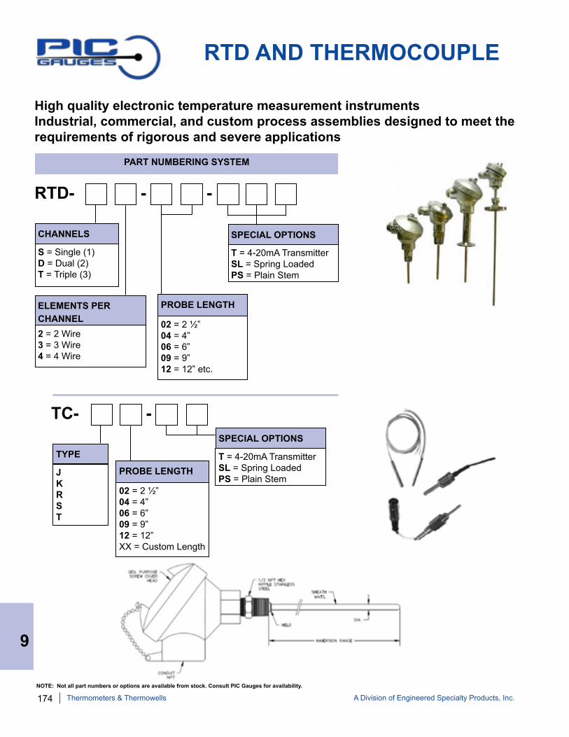
174 A Division of Engineered Specialty Products, Inc.
RTD AND THERMOCOUPLE
High quality electronic temperature measurement instrumentsIndustrial, commercial, and custom process assemblies designed to meet the requirements of rigorous and severe applications
CHANNELS
S = Single (1) D = Dual (2) T = Triple (3)
ELEMENTS PER CHANNEL 2 = 2 Wire 3 = 3 Wire 4 = 4 Wire
PROBE LENGTH
02 = 2 ½” 04 = 4” 06 = 6” 09 = 9” 12 = 12” etc.
SPECIAL OPTIONS
T = 4-20mA Transmitter SL = Spring Loaded PS = Plain Stem
PART NUMBERING SYSTEM
RTD- - -
TYPE
J K R S T
PROBE LENGTH
02 = 2 ½” 04 = 4” 06 = 6” 09 = 9” 12 = 12” XX = Custom Length
SPECIAL OPTIONS
T = 4-20mA Transmitter SL = Spring Loaded PS = Plain Stem
TC- -
9
Thermometers & Thermowells
NOTE: Not all part numbers or options are available from stock. Consult PIC Gauges for availability.
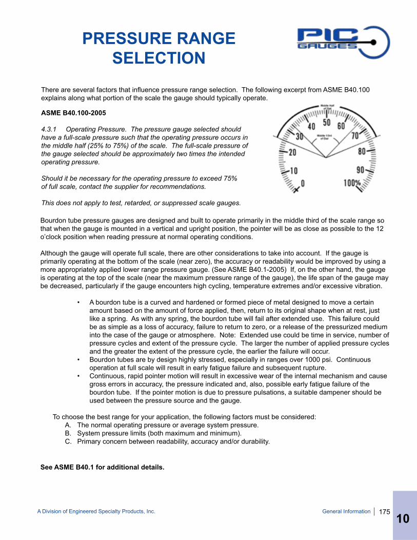
A Division of Engineered Specialty Products, Inc. 175
PRESSURE RANGESELECTION
There are several factors that influence pressure range selection. The following excerpt from ASME B40.100 explains along what portion of the scale the gauge should typically operate.
Bourdon tube pressure gauges are designed and built to operate primarily in the middle third of the scale range so that when the gauge is mounted in a vertical and upright position, the pointer will be as close as possible to the 12 o’clock position when reading pressure at normal operating conditions.
Although the gauge will operate full scale, there are other considerations to take into account. If the gauge is primarily operating at the bottom of the scale (near zero), the accuracy or readability would be improved by using a more appropriately applied lower range pressure gauge. (See ASME B40.1-2005) If, on the other hand, the gauge is operating at the top of the scale (near the maximum pressure range of the gauge), the life span of the gauge may be decreased, particularly if the gauge encounters high cycling, temperature extremes and/or excessive vibration.
• A bourdon tube is a curved and hardened or formed piece of metal designed to move a certain amount based on the amount of force applied, then, return to its original shape when at rest, just like a spring. As with any spring, the bourdon tube will fail after extended use. This failure could be as simple as a loss of accuracy, failure to return to zero, or a release of the pressurized medium into the case of the gauge or atmosphere. Note: Extended use could be time in service, number of pressure cycles and extent of the pressure cycle. The larger the number of applied pressure cycles and the greater the extent of the pressure cycle, the earlier the failure will occur.
• Bourdon tubes are by design highly stressed, especially in ranges over 1000 psi. Continuous operation at full scale will result in early fatigue failure and subsequent rupture.
• Continuous, rapid pointer motion will result in excessive wear of the internal mechanism and cause gross errors in accuracy, the pressure indicated and, also, possible early fatigue failure of the bourdon tube. If the pointer motion is due to pressure pulsations, a suitable dampener should be used between the pressure source and the gauge.
To choose the best range for your application, the following factors must be considered:A. The normal operating pressure or average system pressure.B. System pressure limits (both maximum and minimum).C. Primary concern between readability, accuracy and/or durability.
ASME B40.100-2005
4.3.1 Operating Pressure. The pressure gauge selected should have a full-scale pressure such that the operating pressure occurs in the middle half (25% to 75%) of the scale. The full-scale pressure of the gauge selected should be approximately two times the intended operating pressure.
Should it be necessary for the operating pressure to exceed 75%of full scale, contact the supplier for recommendations.
This does not apply to test, retarded, or suppressed scale gauges.
10General Information
See ASME B40.1 for additional details.

176 A Division of Engineered Specialty Products, Inc.
10
While the temperature range for each individual fill fluid varies, the ranges listed below take into con-sideration the operating temperature permissible for gauges.
Gauge Fill Fluid Operating Temp RangeGlycerine +30° F to 160° F 99.5% Food Grade -1° C to 71° C
Silicone -40° F to 160° F DC 200 1000 cSt -40° C to 71° C
Halocarbon® -40° F to 160° F-40° C to 71° C
For temperatures above 160° F, contact PIC Gauges for assistance in selecting fill fluids rated at higher temperatures and appropriate fill fluids.
LIQUID FILLING/VENTING SEALED GAUGES
• In applications with vibration or pulsation, liquid filling enables reading the dial pointer by
dampening the movement. • Liquid filling should be considered for any
system with dynamic operating conditions because the liquid absorbs vibration and pressure spikes. • In general, liquid filling helps extend the life of a
gauge by reducing wear in the movement. • Because gauges can be filled with different
types of liquids, the degree of protection can be suited to process conditions. See fill fluid considerations below.
• Liquid filled gauges can add to the depend-ability and accuracy of the measuring system for long periods under extreme operating conditions.
Guidelines for determining an appropriate fill fluid include: • Temperature Low Temp Application: Use anti-freeze, low viscosity silicone oil or other comparable liquids High Temp Application: Use high temp rated fluids such as Syltherm® 800 or high viscosity silicone oil• Infrequent but Severe Pressure Spikes: Use
high viscosity fluid• Gauges with Electrical Contacts: Use insula-
tion oils• Chemical Compatibility: Select fill fluid that will
not react with the process media in the event of bourdon tube failure.
• Glycerine is the standard fill fluid for most liquid filled gauges due to its unique fluid properties:
Clarity Viscosity Stability Cost Solubility Low Toxicity• Additionally, glycerine can be mixed with water to
obtain different temperature ratings % Glycerine/Water Low Temp Rating 90/10 29.1° F 70/30 -38.1° F 60/40 -30.5° F 50/50 -9.4° F 40/60 4.3° F 30/70 14.9° F 10/90 29.1° F• When temperature extremes or chemical compat-
ibility fall outside the range of glycerine, note the fill fluid considerations below and consult PIC Gauges for fluid selection.
LIQUID FILLED GAUGE ADVANTAGES GLYCERINE
FILL FLUID CONSIDERATIONS TEMPERATURE RANGES
General Information
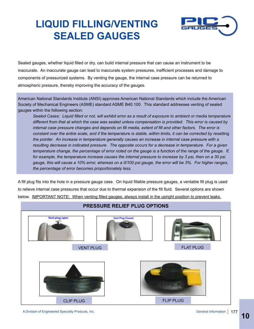
A Division of Engineered Specialty Products, Inc. 177
LIQUID FILLING/VENTING SEALED GAUGES
PRESSURE RELIEF PLUG OPTIONS
VENT PLUG
CLIP PLUG FLIP PLUG
Sealed gauges, whether liquid filled or dry, can build internal pressure that can cause an instrument to be
inaccurate. An inaccurate gauge can lead to inaccurate system pressures, inefficient processes and damage to
components of pressurized systems. By venting the gauge, the internal case pressure can be returned to
atmospheric pressure, thereby improving the accuracy of the gauges.
American National Standards Institute (ANSI) approves American National Standards which include the American Society of Mechanical Engineers (ASME) standard ASME B40.100. This standard addresses venting of sealed gauges within the following section: Sealed Cases: Liquid filled or not, will exhibit error as a result of exposure to ambient or media temperature different from that at which the case was sealed unless compensation is provided. This error is caused by internal case pressure changes and depends on fill media, extent of fill and other factors. The error is constant over the entire scale, and if the temperature is stable, within limits, it can be corrected by resetting the pointer. An increase in temperature generally causes an increase in internal case pressure with a resulting decrease in indicated pressure. The opposite occurs for a decrease in temperature. For a given temperature change, the percentage of error noted on the gauge is a function of the range of the gauge. If, for example, the temperature increase causes the internal pressure to increase by 3 psi, then on a 30 psi gauge, this will cause a 10% error, whereas on a 0/100 psi gauge, the error will be 3%. For higher ranges, the percentage of error becomes proportionately less.
A fill plug fits into the hole in a pressure gauge case. On liquid fillable pressure gauges, a ventable fill plug is used
to relieve internal case pressures that occur due to thermal expansion of the fill fluid. Several options are shown
below. IMPORTANT NOTE: When venting filled gauges, always install in the upright position to prevent leaks.
General Information
10
FLAT PLUG
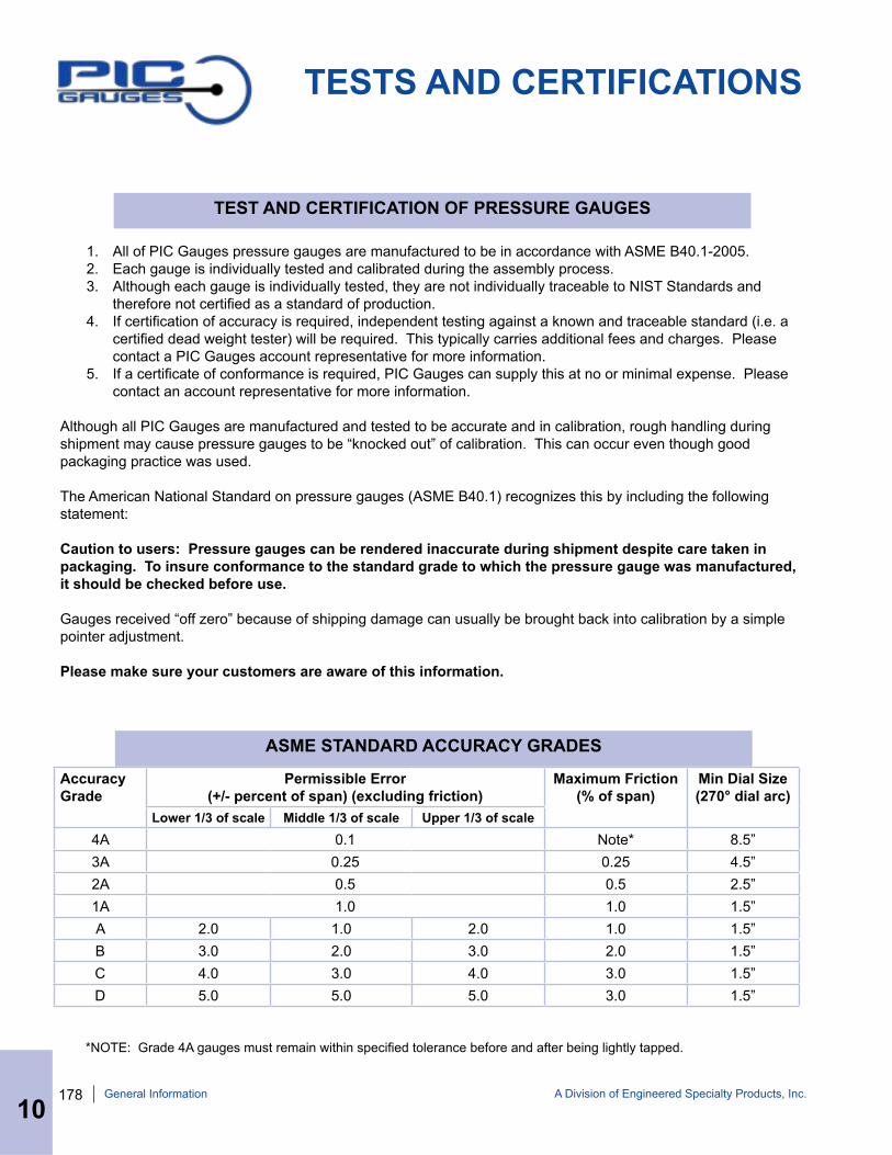
178 A Division of Engineered Specialty Products, Inc.
TESTS AND CERTIFICATIONS
1. All of PIC Gauges pressure gauges are manufactured to be in accordance with ASME B40.1-2005. 2. Each gauge is individually tested and calibrated during the assembly process. 3. Although each gauge is individually tested, they are not individually traceable to NIST Standards and
therefore not certified as a standard of production. 4. If certification of accuracy is required, independent testing against a known and traceable standard (i.e. a
certified dead weight tester) will be required. This typically carries additional fees and charges. Please contact a PIC Gauges account representative for more information.
5. If a certificate of conformance is required, PIC Gauges can supply this at no or minimal expense. Please contact an account representative for more information.
Although all PIC Gauges are manufactured and tested to be accurate and in calibration, rough handling during shipment may cause pressure gauges to be “knocked out” of calibration. This can occur even though good packaging practice was used.
The American National Standard on pressure gauges (ASME B40.1) recognizes this by including the following statement:
Caution to users: Pressure gauges can be rendered inaccurate during shipment despite care taken in packaging. To insure conformance to the standard grade to which the pressure gauge was manufactured, it should be checked before use.
Gauges received “off zero” because of shipping damage can usually be brought back into calibration by a simple pointer adjustment.
Please make sure your customers are aware of this information.
Accuracy Grade
Permissible Error (+/- percent of span) (excluding friction)
Maximum Friction (% of span)
Min Dial Size (270° dial arc)
Lower 1/3 of scale Middle 1/3 of scale Upper 1/3 of scale4A 0.1 Note* 8.5”3A 0.25 0.25 4.5”2A 0.5 0.5 2.5”1A 1.0 1.0 1.5”A 2.0 1.0 2.0 1.0 1.5”B 3.0 2.0 3.0 2.0 1.5”C 4.0 3.0 4.0 3.0 1.5”D 5.0 5.0 5.0 3.0 1.5”
ASME STANDARD ACCURACY GRADES
TEST AND CERTIFICATION OF PRESSURE GAUGES
*NOTE: Grade 4A gauges must remain within specified tolerance before and after being lightly tapped.
General Information
10

A Division of Engineered Specialty Products, Inc. 179General Information
10
LIMITED WARRANTY /RETURNS
PIC Gauges, a division of Engineered Specialty Products Inc., warrants all of its mechanical instruments to be free from defects in materials and workmanship. Liability under this warranty is limited to repair or replacement F.O.B. factory of any products which prove to be defective or repayment of the purchase price at PIC Gauges’ option. Instruments must be returned, transportation prepaid, within one year from date of purchase.
This warranty should not apply to the following:
A. The product has been subjected to misuse, neglect, abuse, accident, incorrect mounting, improper use or misapplication.
B. The performance of any system of which PIC Gauges’ products are a component part. C. The product has been exposed to any other service, range or environment of greater severity than that for
which the products were designed. D. The product has been altered or repaired by anyone except PIC Gauges or its authorized service agencies.E. The serial number or date code has been removed, defaced or changed. F. The actual pressure and temperature occurring exceed the values specified for PIC Gauges products.
Unless otherwise specified in a manual or warranty card, or agreed to in writing signed by an authorized PIC Gauges representative, PIC Gauges products shall be warranted for one year from the date of sale.
The warranty is in lieu of all other warranties expressed or implied, and of all obligations or liabilities on its part for damages including but not limited to consequential damages, following the use or misuse of instruments sold by PIC Gauges. No agent is authorized to assume for PIC Gauges any liability except as set forth above.
LIMITED WARRANTY
10
RETURNSWhat items can be returned? Any standard product (excluding special order items) may be returned within 30 days for an exchange or refund (less shipping charges).
Shipping discrepancies must be reported within 7 days.
Who pays for return shipping?The customer is responsible for return shipping costs unless PIC Gauges has made an error in shipment or an item arrives damaged or defective. In the event of a shipment error or a damaged/defective item, PIC Gauges will be responsible for the cost of ground shipping only, and only for returns made within 30 days of the purchase date.
Please contact PIC Gauges if your defective merchandise is less than $10.00 in value as returning the merchandise may not be necessary.
How do I return an item? Contact PIC Gauges for an RGA number and shipping instructions.
DisclaimerAll prices and policies are subject to change without notice.

180 A Division of Engineered Specialty Products, Inc.
PRESSURE CONVERSION CHARTps
iAT
Ms
In. H
gIn
.wc
Oz/
in²
mm
w
ccm
wc
mba
rPa
(N
/m²)
mm
Hg
(Tor
r)cm
Hg
Kg/
cm²
kPa
BA
Rm
Pa
psi
114
.70.
4912
0.03
610.
0625
0.00
1421
0.01
421
0.01
450.
0001
450.
0193
40.
1934
14.2
20.
1450
414
.504
145.
04ps
i
ATM
s0.
0681
10.
0334
20.
0024
60.
0042
50.
0000
970.
0009
670.
0009
870.
0000
10.
0013
160.
0131
60.
968
0.00
987
0.98
79.
869
ATM
s
In. H
g2.
036
29.9
21
0.07
350.
1273
0.00
289
0.02
890.
0295
0.00
0295
0.03
940.
394
28.9
60.
295
29.5
329
5.3
In. H
g
In. w
c27
.71
407.
213
.61
11.
732
0.03
940.
3937
0.40
120.
0040
20.
536
5.35
839
4.1
4.01
940
1.9
4019
In. w
c
Oz/
in²
1623
5.1
7.85
80.
5775
10.
0227
0.22
70.
2321
0.00
232
0.31
03.
122
7.6
2.32
123
2.1
2321
Oz/
in²
mm
wc
703.
810
,343
345.
725
.443
.986
110
10.2
10.
102
13.6
113
6.1
100,
010
102.
0710
,210
102,
074
mm
wc
cm w
c70
.38
1,03
4.30
34.5
72.
544.
400.
11
1.02
10.
0102
1.36
113
.61
1,00
110
.207
1021
10,2
07cm
wc
mba
r68
.95
1,01
333
.86
2.48
84.
310.
098
0.98
10.
011.
333
13.3
398
0.7
101,
000
10,0
00m
bar
Pa
(N/m
²)6,
895
101,
325
3,38
624
8.8
431
9.8
9810
01
133.
31,
333
98,0
671,
000
100,
000
1,00
0,00
0Pa
(N
/m²)
mm
Hg
(Tor
r)51
.715
760
25.4
1.86
63.
232
0.07
350.
735
0.75
0.00
751
1073
5.6
7.05
750
7,50
0m
m H
g (T
orr)
cm H
g5.
1776
2.54
0.18
70.
323
0.00
735
0.07
350.
075
0.00
075
0.1
173
.56
0.75
7575
0cm
Hg
Kg/
cm²
0.07
041.
033
0.03
450.
0025
40.
0044
0.00
010.
001
0.00
102
0.00
001
0.00
136
0.01
361
0.01
021.
0210
.2K
g/cm
²
kPa
6.89
510
1.3
3.38
60.
249
0.43
10.
0098
0.09
80.
10.
001
0.13
331.
333
98.0
71
100
1,00
0kP
a
BA
R0.
0689
1.01
30.
0339
0.00
249
0.00
431
0.00
0098
0.00
098
0.00
10.
0000
10.
0013
330.
0133
30.
981
0.01
110
BA
R
mPa
0.00
690.
1013
0.00
339
0.00
025
0.00
043
0.00
001
0.00
010.
0001
0.00
0001
0.00
0133
0.00
133
0.09
810.
001
0.1
1m
Pa
Low
Pre
ssur
e
Stan
dard
Met
ric
General Information
10
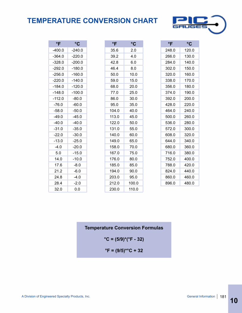
A Division of Engineered Specialty Products, Inc. 181
TEMPERATURE CONVERSION CHART
°F °C-400.0 -240.0-364.0 -220.0-328.0 -200.0-292.0 -180.0-256.0 -160.0-220.0 -140.0-184.0 -120.0-148.0 -100.0-112.0 -80.0-76.0 -60.0-58.0 -50.0-49.0 -45.0-40.0 -40.0-31.0 -35.0-22.0 -30.0-13.0 -25.0-4.0 -20.05.0 -15.014.0 -10.017.6 -8.021.2 -6.024.8 -4.028.4 -2.032.0 0.0
°F °C35.6 2.039.2 4.042.8 6.046.4 8.050.0 10.059.0 15.068.0 20.077.0 25.086.0 30.095.0 35.0104.0 40.0113.0 45.0122.0 50.0131.0 55.0140.0 60.0149.0 65.0158.0 70.0167.0 75.0176.0 80.0185.0 85.0194.0 90.0203.0 95.0212.0 100.0230.0 110.0
°F °C248.0 120.0266.0 130.0284.0 140.0302.0 150.0320.0 160.0338.0 170.0356.0 180.0374.0 190.0392.0 200.0428.0 220.0464.0 240.0500.0 260.0536.0 280.0572.0 300.0608.0 320.0644.0 340.0680.0 360.0716.0 380.0752.0 400.0788.0 420.0824.0 440.0860.0 460.0896.0 480.0
Temperature Conversion Formulas
°C = (5/9)*(°F - 32)
°F = (9/5)*°C + 32
General Information
10

182 A Division of Engineered Specialty Products, Inc.General Information
10
PTS PRESSURE TRANSMITTER
PTS -A -3000 -P1 -C4Model Type Pressure Range Process Connection Electrical Connection
PTS A: 4 - 20 mA (2 wire)B: 0 - 5V (3 wire)C: 0 - 10V(3 wire)
D: 0.5 - 4.5V (3 wire)E: 1 - 5V (3 wire)
Specify Pressure Range Required
Manufactured to Order
P1 - 1/4 NPTP2 - 1/4 BSPP* P3 - 7/16X20 SAE MALE
P4 - 7/16X20 SAE FEMALE SCHRADER VALVE
*Non Standard
C1 - Packard PlugC2 - M12-4 Pin
C3 - Cable (Specify cable length - minimum 3 ft.)
C4 - DIN 43650CC5 - 1/2 NPT MALE Conduit
Constult PIC Gauges for other Terminal Options
ORDERING INFORMATION
ELECTRICAL: Output: 4 - 20 mA (2 wire) 0 - 5V, 0 - 10V, 0.5 - 4.5V, 1 - 5V (3 wire)Supply: 9 - 36 VDC (2 wire), 5 VDC 3 wire optional
OPERATING TEMPERATURE: -40° F to 212° F (-40°C to 100°C) ACCURACY: +/- 0.5% (Full Scale) - Standard+/- 0.25% (Full Scale) - Special Order Only
INSULATION: >100m Ω@50V
PROTECTION: IP 68 (cable or packard)IP 65 with DIN
STORAGE TEMPERATURE: -58°F to 257°F (-50°C to 125°C)
RESPONSE TIME: <10 milliseconds
MATERIAL: Stainless Steel Body
PRESSURE RANGE: 0 - 8700 psi(0 - 600 BAR)
COMPENSATION TEMPERATURE: 14°F to 176°F (-10°C to 80°C)
OVERLOAD PRESSURE: 150% Full Scale SENSING ELEMENT: Silicon Chip with 316 Stainless Steel Protection
MEDIUM COMPATIBILITY: Corrosive medium compatible with 316 stainless steel
The PTS pressure transmitters offer high quality, high stability, stainless steel compact design, ideal for the industrial environment. The transmitters are widely used in air compressors, air conditioning and refrigeration equipment, automotive and hydraulic control.
ApprovedMEMS Technology
Wiring Data InformationDIN Connector PIN Function
Signal Output Pin 1 Pin 2 Pin 3 Pin 4
mA Supply V+ Output N/A N/A
V Supply V+ Common Output N/A
Cable Connector WIRE Function
Signal Output RED BLUE YELLOW BLACK
mA Supply V+ Output N/A N/A
V Supply V+ Output Common N/A
Packard Plug PIN/WIRE Function
Signal Output A/BLACK B/RED C/GREEN
mA N/A Supply V+ Output
V Common Supply V+ Output
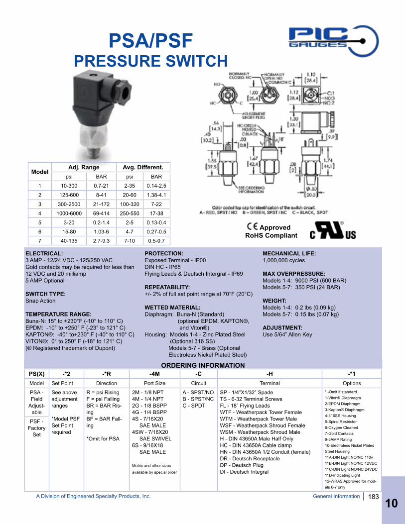
A Division of Engineered Specialty Products, Inc. 183General Information
10
PSA/PSF PRESSURE SWITCH
ELECTRICAL: 3 AMP - 12/24 VDC - 125/250 VACGold contacts may be required for less than 12 VDC and 20 milliamp5 AMP Optional
SWITCH TYPE: Snap Action
TEMPERATURE RANGE: Buna-N: 15° to +230°F (-10° to 110° C)EPDM: -10° to +250° F (-23° to 121° C)KAPTON®: -40° to+230° F (-40° to 110° C) VITON®: 0° to 250° F (-18° to 121° C)(® Registered trademark of Dupont)
PS(X) -*2 -*R -4M -C -H -*1Model Set Point Direction Port Size Circuit Terminal Options
PSA - Field
Adjust-able
See above adjustment ranges
*Model PSF Set Point required
R = psi RisingF = psi FallingBR = BAR Ris-ingBF = BAR Fall-ing
*Omit for PSA
2M - 1/8 NPT4M - 1/4 NPT2G - 1/8 BSPP4G - 1/4 BSPP4S - 7/16X20 SAE MALE4SW - 7/16X20 SAE SWIVEL6S - 9/16X18 SAE MALE
Metric and other sizes
available by special order
A - SPST/NOB - SPST/NCC - SPDT
SP - 1/4”X1/32” SpadeTS - 6-32 Terminal ScrewsFL - 18” Flying LeadsWTF - Weatherpack Tower FemaleWTM - Weatherpack Tower MaleWSF - Weatherpack Shroud FemaleWSM - Weatherpack Shroud MaleH - DIN 43650A Male Half OnlyHC - DIN 43650A Cable clampHN - DIN 43650A 1/2 Conduit (female)DR - Deutsch ReceptacleDP - Deutsch PlugDI - Deutsch Integral
* -Omit if standard1-Viton® Diaphragm2-EPDM Diaphragm3-Kapton® Diaphragm4-316SS Housing5-Spiral Restrictor6-Oxygen Cleaned7-Gold Contacts9-5AMP Rating10-Electroless Nickel Plated Steel Housing11A-DIN Light NO/NC 110v11B-DIN Light NO/NC 12VDC11C-DIN Light NO/NC 24VDC11D-Indicating Light12-WRAS Approved for mod-els 6-7 only
PSF - Factory
Set
ORDERING INFORMATION
ModelAdj. Range Avg. Different.
psi BAR psi BAR
1 10-300 0.7-21 2-35 0.14-2.5
2 125-600 8-41 20-60 1.38-4.1
3 300-2500 21-172 100-320 7-22
4 1000-6000 69-414 250-550 17-38
5 3-20 0.2-1.4 2-5 0.13-0.4
6 15-80 1.03-6 4-7 0.27-0.5
7 40-135 2.7-9.3 7-10 0.5-0.7
PROTECTION: Exposed Terminal - IP00DIN HC - IP65Flying Leads & Deutsch Intergral - IP69
REPEATABILITY: +/- 2% of full set point range at 70°F (20°C)
WETTED MATERIAL: Diaphragm: Buna-N (Standard) (optional EPDM, KAPTON®, and Viton®)Housing: Models 1-4 - Zinc Plated Steel (Optional 316 SS) Models 5-7 - Brass (Optional Electroless Nickel Plated Steel)
MECHANICAL LIFE: 1,000,000 cycles
MAX OVERPRESSURE: Models 1-4: 9000 PSI (600 BAR) Models 5-7: 350 PSI (24 BAR)
WEIGHT: Models 1-4: 0.2 lbs (0.09 kg) Models 5-7: 0.15 lbs (0.07 kg)
ADJUSTMENT: Use 5/64” Allen Key
ApprovedRoHS Compliant

184 A Division of Engineered Specialty Products, Inc.
NEW PRODUCTS & CUSTOM SOLUTIONS
General Information
Clamshell Packaging UPC Codes Custom Displays
Gauge with Capillary & Diaphragm Seal - High Temp Application Custom Connections
Female
Specialty Pressure Transmitters Temperature Switches
JIC/UNF/Flare
SAELong Socket
OEM Pressure Switches