Pressman Ch 8 Analysis Modeling
34
Chapter 8 Analysis Modeling - Requirements analysis - Flow-oriented modeling - Scenario-based modeling - Class-based modeling - Behavioral modeling (Source: Pressman, R. Software Engineering: A Practitioner’s Approach . McGraw-Hill, 2005)
-
Upload
sindu-rangaswamy -
Category
Documents
-
view
98 -
download
10
description
Software engineering
Transcript of Pressman Ch 8 Analysis Modeling
Chapter 8
Analysis Modeling
- Requirements analysis
- Flow-oriented modeling
- Scenario-based modeling
- Class-based modeling
- Behavioral modeling
(Source: Pressman, R. Software Engineering: A Practitioner’s Approach. McGraw-Hill, 2005)
2
Goals of Analysis Modeling
• Provides the first technical representation of a system
• Is easy to understand and maintain
• Deals with the problem of size by partitioning the system
• Uses graphics whenever possible
• Differentiates between essential information versus implementation information
• Helps in the tracking and evaluation of interfaces
• Provides tools other than narrative text to describe software logic and policy
3
A Set of Models
• Flow-oriented modeling – provides an indication of how data objects are transformed by a set of processing functions
• Scenario-based modeling – represents the system from the user's point of view
• Class-based modeling – defines objects, attributes, and relationships• Behavioral modeling – depicts the states of the classes and the
impact of events on these states
Requirements Analysis
5
Purpose
• Specifies the software's operational characteristics• Indicates the software's interfaces with other system elements• Establishes constraints that the software must meet• Provides the software designer with a representation of information,
function, and behavior– This is later translated into architectural, interface, class/data and
component-level designs
• Provides the developer and customer with the means to assess quality once the software is built
6
Overall Objectives
• Three primary objectives– To describe what the customer requires– To establish a basis for the creation of a software design– To define a set of requirements that can be validated once the software is
built
• All elements of an analysis model are directly traceable to parts of the design model, and some parts overlap
7
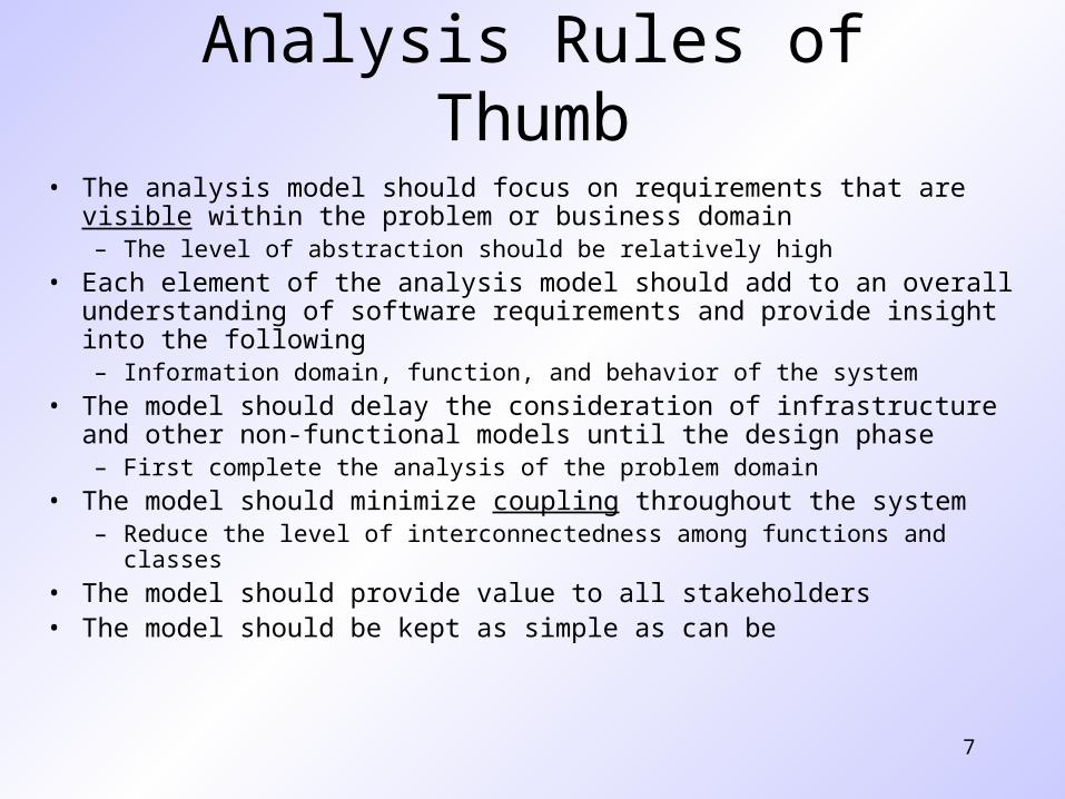
Analysis Rules of Thumb
• The analysis model should focus on requirements that are visible within the problem or business domain – The level of abstraction should be relatively high
• Each element of the analysis model should add to an overall understanding of software requirements and provide insight into the following– Information domain, function, and behavior of the system
• The model should delay the consideration of infrastructure and other non-functional models until the design phase– First complete the analysis of the problem domain
• The model should minimize coupling throughout the system– Reduce the level of interconnectedness among functions and classes
• The model should provide value to all stakeholders• The model should be kept as simple as can be
8
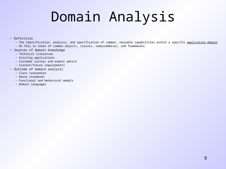
Domain Analysis• Definition
– The identification, analysis, and specification of common, reusable capabilities within a specific application domain– Do this in terms of common objects, classes, subassemblies, and frameworks
• Sources of domain knowledge– Technical literature– Existing applications– Customer surveys and expert advice– Current/future requirements
• Outcome of domain analysis– Class taxonomies– Reuse standards– Functional and behavioral models– Domain languages
9
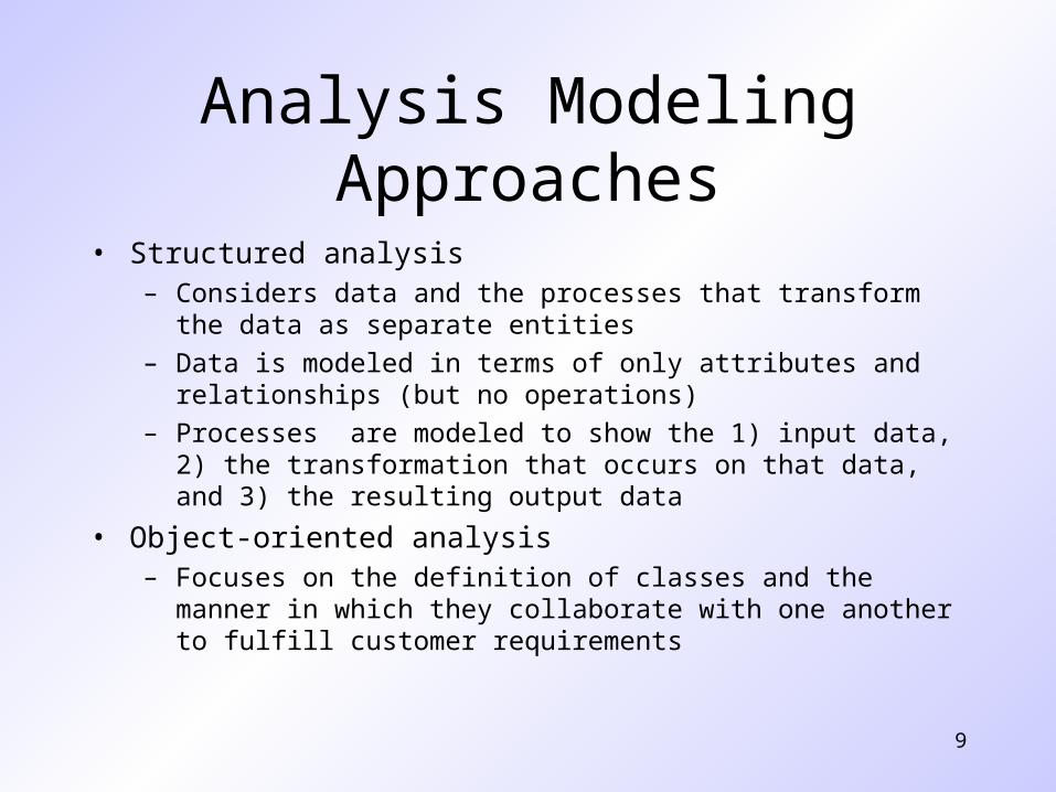
Analysis Modeling Approaches
• Structured analysis– Considers data and the processes that transform the data as separate
entities
– Data is modeled in terms of only attributes and relationships (but no operations)
– Processes are modeled to show the 1) input data, 2) the transformation that occurs on that data, and 3) the resulting output data
• Object-oriented analysis– Focuses on the definition of classes and the manner in which they
collaborate with one another to fulfill customer requirements
10
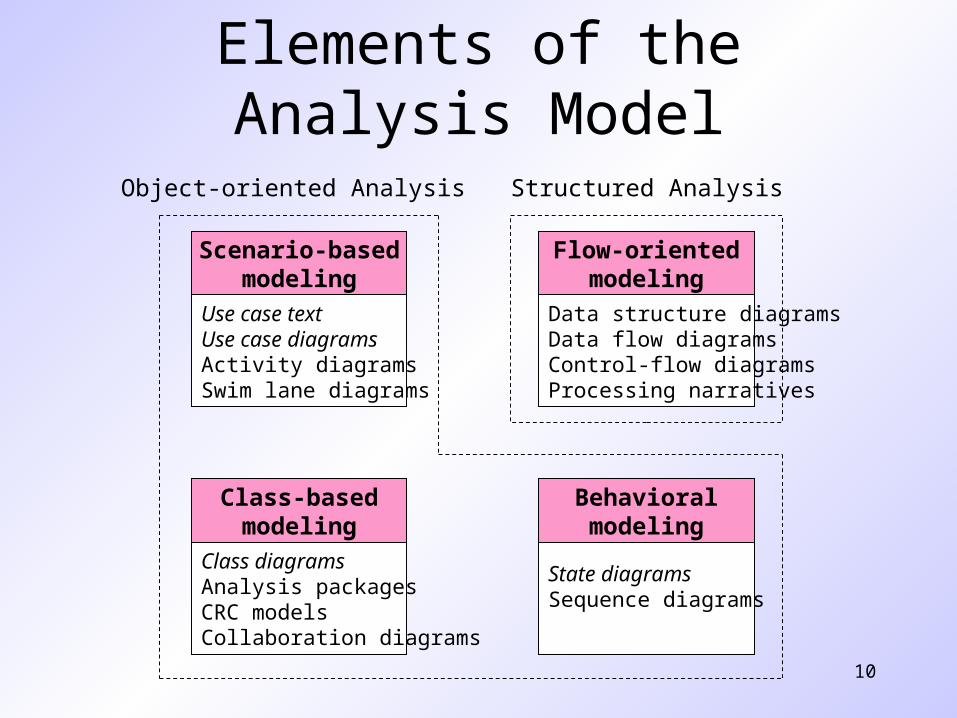
Elements of the Analysis Model
Use case textUse case diagramsActivity diagramsSwim lane diagrams
Scenario-basedmodeling
Class diagramsAnalysis packagesCRC modelsCollaboration diagrams
Class-basedmodeling
Data structure diagramsData flow diagramsControl-flow diagramsProcessing narratives
Flow-orientedmodeling
State diagramsSequence diagrams
Behavioralmodeling
Structured AnalysisObject-oriented Analysis
Flow-oriented Modeling
12
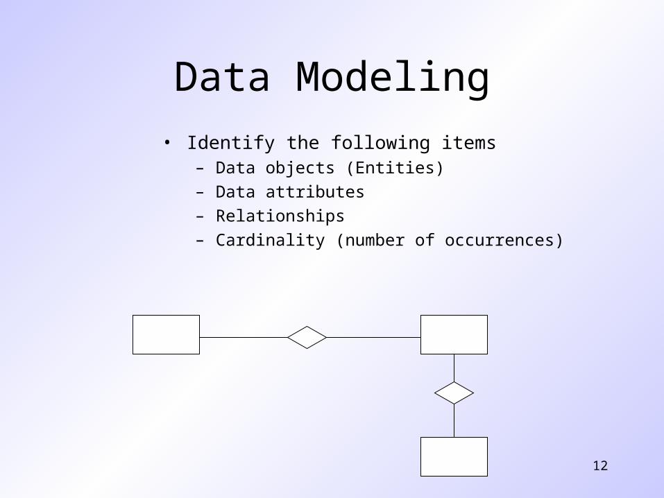
Data Modeling
• Identify the following items– Data objects (Entities)
– Data attributes
– Relationships
– Cardinality (number of occurrences)
13
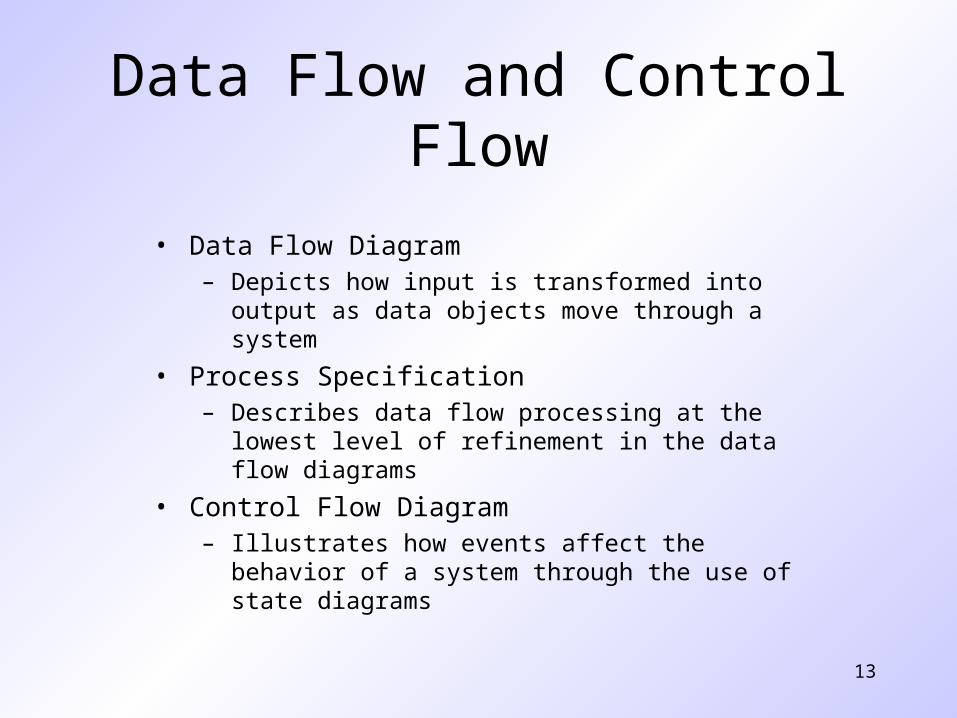
Data Flow and Control Flow
• Data Flow Diagram– Depicts how input is transformed into output as data objects
move through a system
• Process Specification– Describes data flow processing at the lowest level of
refinement in the data flow diagrams
• Control Flow Diagram– Illustrates how events affect the behavior of a system through
the use of state diagrams
14
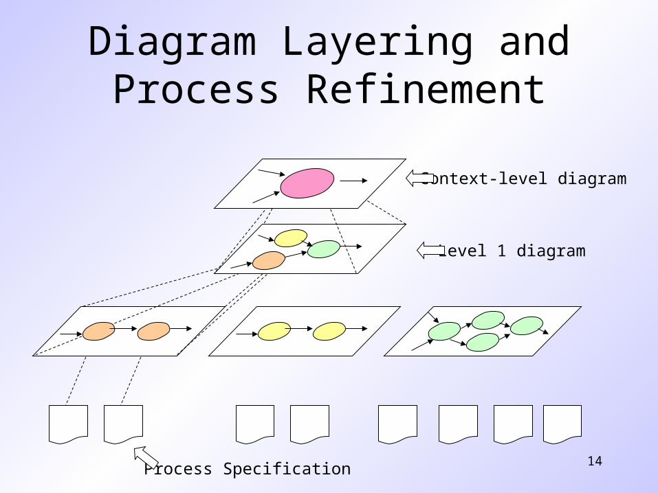
Diagram Layering and Process Refinement
Context-level diagram
Level 1 diagram
Process Specification
Scenario-based Modeling
16
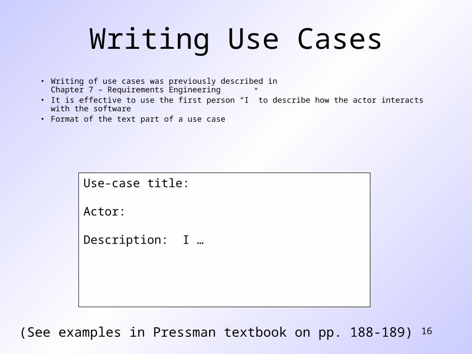
Writing Use Cases• Writing of use cases was previously described in
Chapter 7 – Requirements Engineering• It is effective to use the first person “I” to describe how the actor interacts with the software • Format of the text part of a use case
(See examples in Pressman textbook on pp. 188-189)
Use-case title:
Actor:
Description: I …
17
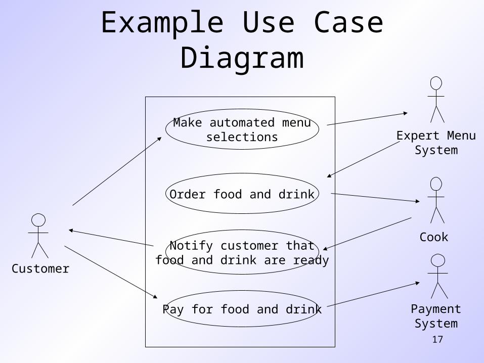
Example Use Case Diagram
Make automated menuselections
Order food and drink
Pay for food and drink
Notify customer thatfood and drink are ready
Customer
Cook
PaymentSystem
Expert MenuSystem
18
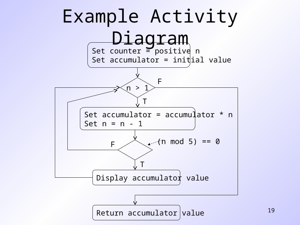
Activity Diagrams
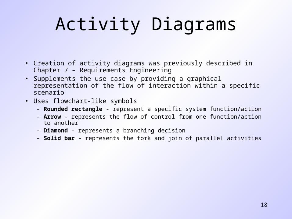
• Creation of activity diagrams was previously described in Chapter 7 – Requirements Engineering
• Supplements the use case by providing a graphical representation of the flow of interaction within a specific scenario
• Uses flowchart-like symbols– Rounded rectangle - represent a specific system function/action– Arrow - represents the flow of control from one function/action to another– Diamond - represents a branching decision– Solid bar – represents the fork and join of parallel activities
19
Example Activity DiagramSet counter = positive nSet accumulator = initial value
n > 1
Set accumulator = accumulator * nSet n = n - 1
(n mod 5) == 0
Display accumulator value
Return accumulator value
T
F
T
F
Class-based Modeling
21
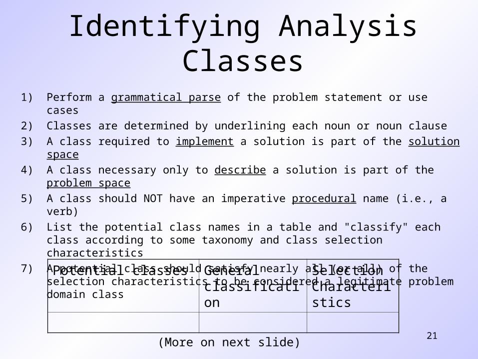
Identifying Analysis Classes
1) Perform a grammatical parse of the problem statement or use cases
2) Classes are determined by underlining each noun or noun clause
3) A class required to implement a solution is part of the solution space
4) A class necessary only to describe a solution is part of the problem space
5) A class should NOT have an imperative procedural name (i.e., a verb)
6) List the potential class names in a table and "classify" each class according to some taxonomy and class selection characteristics
7) A potential class should satisfy nearly all (or all) of the selection characteristics to be considered a legitimate problem domain class
(More on next slide)
Potential classes General classification
Selection Characteristics
22
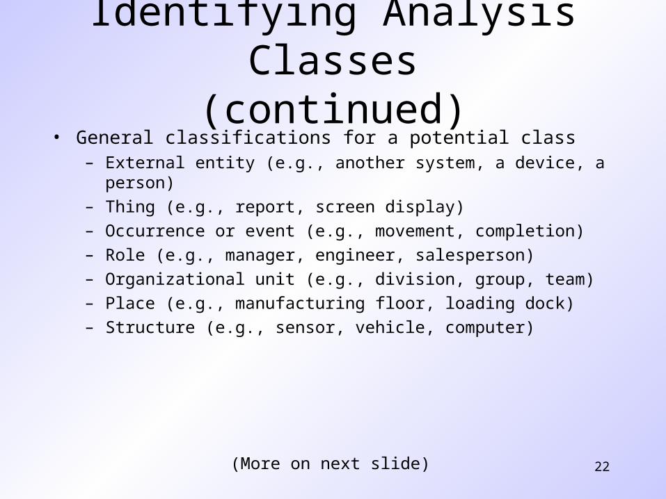
• General classifications for a potential class– External entity (e.g., another system, a device, a person)
– Thing (e.g., report, screen display)
– Occurrence or event (e.g., movement, completion)
– Role (e.g., manager, engineer, salesperson)
– Organizational unit (e.g., division, group, team)
– Place (e.g., manufacturing floor, loading dock)
– Structure (e.g., sensor, vehicle, computer)
Identifying Analysis Classes(continued)
(More on next slide)
23
Identifying Analysis Classes (continued)
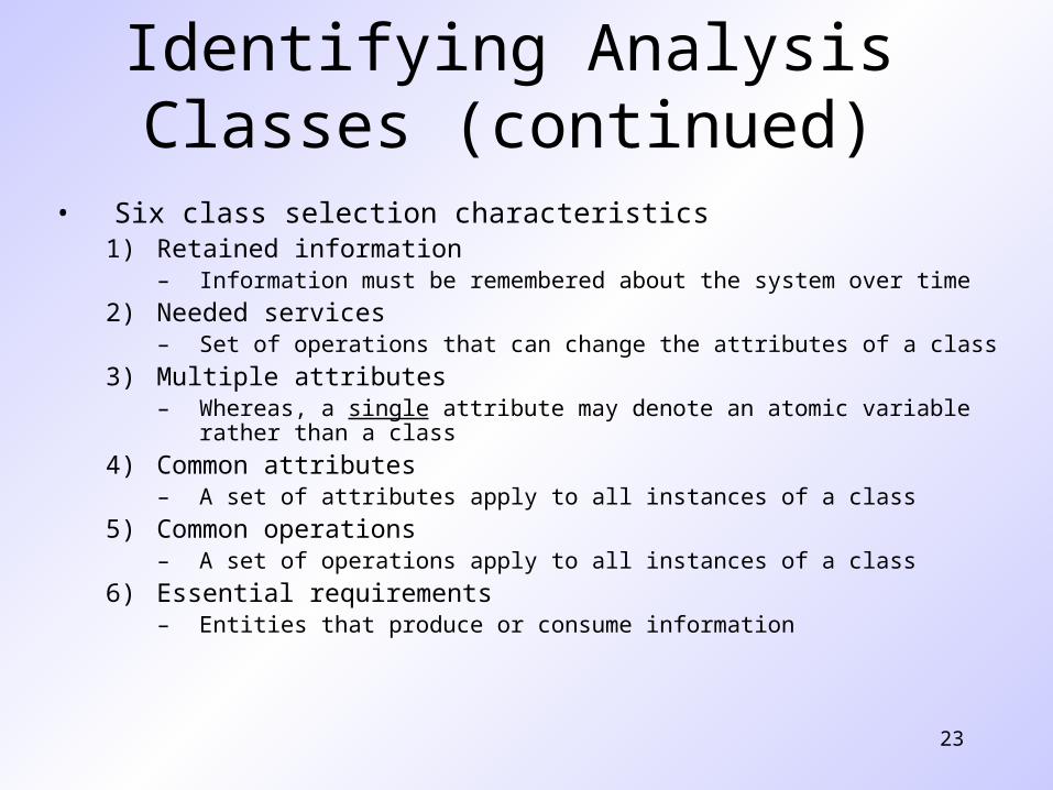
• Six class selection characteristics1) Retained information
– Information must be remembered about the system over time
2) Needed services– Set of operations that can change the attributes of a class
3) Multiple attributes– Whereas, a single attribute may denote an atomic variable rather than a class
4) Common attributes– A set of attributes apply to all instances of a class
5) Common operations– A set of operations apply to all instances of a class
6) Essential requirements– Entities that produce or consume information
24
Defining Attributes of a Class
• Attributes of a class are those nouns from the grammatical parse that reasonably belong to a class
• Attributes hold the values that describe the current properties or state of a class
• An attribute may also appear initially as a potential class that is later rejected because of the class selection criteria
• In identifying attributes, the following question should be answered – What data items (composite and/or elementary) will fully define a specific
class in the context of the problem at hand?
• Usually an item is not an attribute if more than one of them is to be associated with a class
25
Defining Operations of a Class
• Operations define the behavior of an object• Four categories of operations
– Operations that manipulate data in some way to change the state of an object (e.g., add, delete, modify)
– Operations that perform a computation– Operations that inquire about the state of an object– Operations that monitor an object for the occurrence of a controlling event
• An operation has knowledge about the state of a class and the nature of its associations
• The action performed by an operation is based on the current values of the attributes of a class
• Using a grammatical parse again, circle the verbs; then select the verbs that relate to the problem domain classes that were previously identified
26
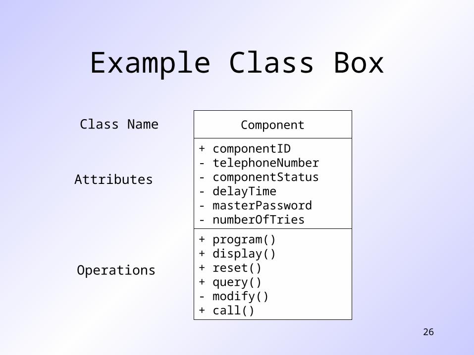
Example Class Box
Component
+ componentID- telephoneNumber- componentStatus- delayTime- masterPassword- numberOfTries
+ program()+ display()+ reset()+ query()- modify()+ call()
Class Name
Attributes
Operations
27
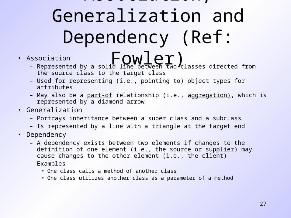
Association, Generalization and Dependency (Ref: Fowler)
• Association– Represented by a solid line between two classes directed from the source class to the
target class– Used for representing (i.e., pointing to) object types for attributes– May also be a part-of relationship (i.e., aggregation), which is represented by a
diamond-arrow
• Generalization– Portrays inheritance between a super class and a subclass– Is represented by a line with a triangle at the target end
• Dependency– A dependency exists between two elements if changes to the definition of one
element (i.e., the source or supplier) may cause changes to the other element (i.e., the client)
– Examples • One class calls a method of another class• One class utilizes another class as a parameter of a method
28
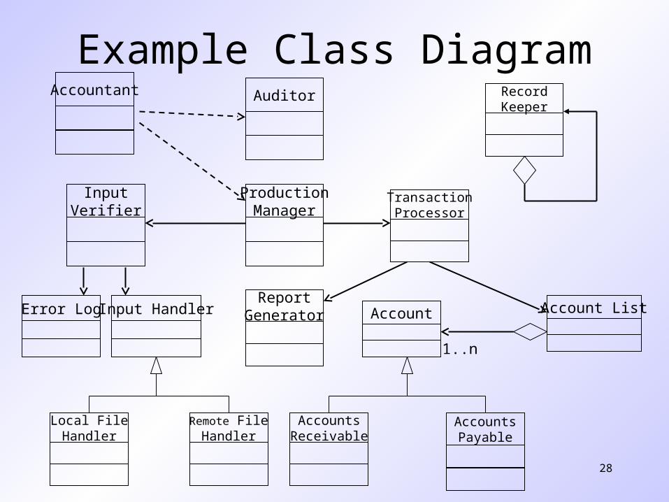
Example Class Diagram
1..n
ProductionManager
Auditor RecordKeeper
ReportGenerator
TransactionProcessor
Account
AccountsPayable
AccountsReceivable
InputVerifier
Error Log Input Handler
Local FileHandler
Remote FileHandler
Account List
Accountant
Behavioral Modeling
30
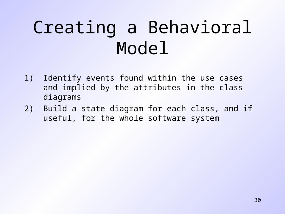
Creating a Behavioral Model
1) Identify events found within the use cases and implied by the attributes in the class diagrams
2) Build a state diagram for each class, and if useful, for the whole software system
31
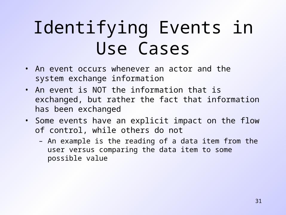
Identifying Events in Use Cases
• An event occurs whenever an actor and the system exchange information
• An event is NOT the information that is exchanged, but rather the fact that information has been exchanged
• Some events have an explicit impact on the flow of control, while others do not– An example is the reading of a data item from the user versus comparing
the data item to some possible value
32
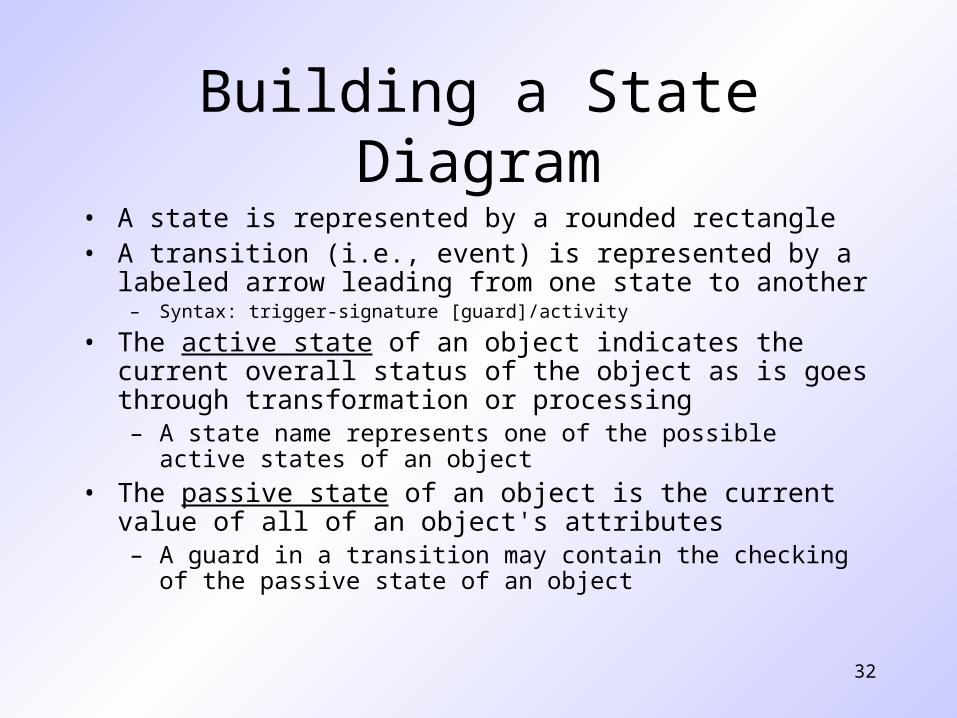
Building a State Diagram• A state is represented by a rounded rectangle• A transition (i.e., event) is represented by a labeled arrow leading from
one state to another – Syntax: trigger-signature [guard]/activity
• The active state of an object indicates the current overall status of the object as is goes through transformation or processing– A state name represents one of the possible active states of an object
• The passive state of an object is the current value of all of an object's attributes– A guard in a transition may contain the checking of the passive state of an
object
33
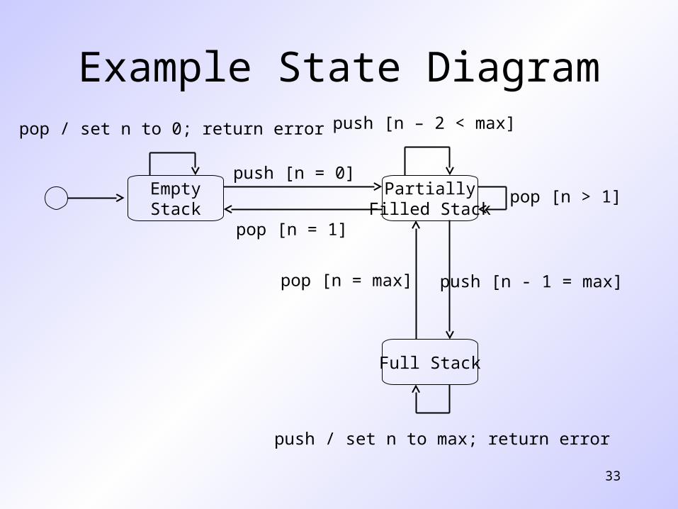
Example State Diagram
EmptyStack
PartiallyFilled Stack
Full Stack
push [n = 0]
pop [n = 1]
push [n - 1 = max]
push [n – 2 < max]
pop [n > 1]
pop [n = max]
pop / set n to 0; return error
push / set n to max; return error
34
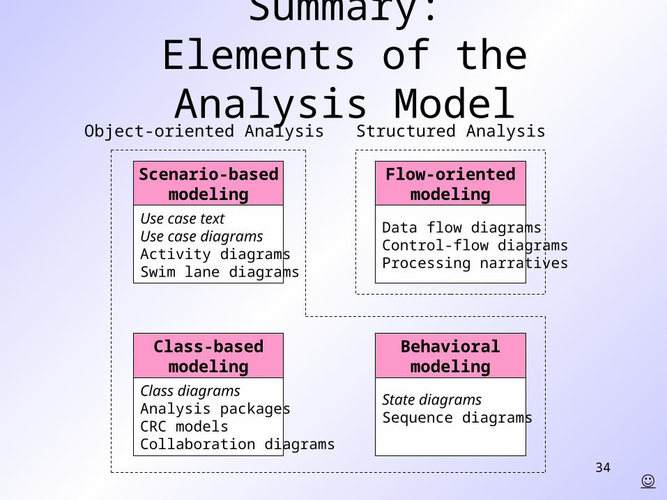
Summary:Elements of the Analysis Model
Use case textUse case diagramsActivity diagramsSwim lane diagrams
Scenario-basedmodeling
Class diagramsAnalysis packagesCRC modelsCollaboration diagrams
Class-basedmodeling
Data flow diagramsControl-flow diagramsProcessing narratives
Flow-orientedmodeling
State diagramsSequence diagrams
Behavioralmodeling
Structured AnalysisObject-oriented Analysis