PressFIT mounting technology - Infineon Technologies
19
Application Note Please read the Important Notice and Warnings at the end of this document Revision 2.1 www.infineon.com 2016-07-01 AN2007-09 PressFIT mounting technology Mounting instruction for PressFIT modules with forked pins About this document Scope and purpose This application note provides a guideline how to use and implement Econo modules using PressFIT connectors. The values and hints given in this document should not be handled like datasheet values. Intended audience This document is intended for any expert using Infineon’s Econo modules. Table of Contents About this document ............................................................................................................................................. 1 Table of Contents .................................................................................................................................................. 1 1 General............................................................................................................................................... 2 2 PCB Requirements ............................................................................................................................. 3 3 Mounting a PCB onto the IGBT module equipped with PressFIT pins ................................................ 5 3.1 Pressing-in several modules at the same time ...................................................................................... 9 4 Heat sink requirements .................................................................................................................... 10 5 Application of the thermal compound ............................................................................................. 11 5.1 Press-In process with TIM Modules....................................................................................................... 12 6 Bolts to mount modules to the heatsink .......................................................................................... 13 7 Mounting modules to the heatsink .................................................................................................. 14 8 Storage/application and transport of IGBT modules ....................................................................... 16 9 Disassembly ..................................................................................................................................... 17 Revision History ................................................................................................................................................... 18
Transcript of PressFIT mounting technology - Infineon Technologies

Application Note Please read the Important Notice and Warnings at the end of this document Revision 2.1
www.infineon.com 2016-07-01
AN2007-09
PressFIT mounting technology
Mounting instruction for PressFIT modules with forked pins
About this document
Scope and purpose
This application note provides a guideline how to use and implement Econo modules using PressFIT connectors. The values and hints given in this document should not be handled like datasheet values.
Intended audience
This document is intended for any expert using Infineon’s Econo modules.
Table of Contents
About this document ............................................................................................................................................. 1
Table of Contents .................................................................................................................................................. 1
1 General ............................................................................................................................................... 2
2 PCB Requirements ............................................................................................................................. 3
3 Mounting a PCB onto the IGBT module equipped with PressFIT pins ................................................ 5 3.1 Pressing-in several modules at the same time ...................................................................................... 9
4 Heat sink requirements .................................................................................................................... 10
5 Application of the thermal compound ............................................................................................. 11
5.1 Press-In process with TIM Modules....................................................................................................... 12
6 Bolts to mount modules to the heatsink .......................................................................................... 13
7 Mounting modules to the heatsink .................................................................................................. 14
8 Storage/application and transport of IGBT modules ....................................................................... 16
9 Disassembly ..................................................................................................................................... 17
Revision History ................................................................................................................................................... 18

Application Note 2 Revision 2.1
2016-07-01
PressFIT mounting technology Mounting instruction for PressFIT modules with forked pins
General
1 General
IGBT modules are electrostatic sensitive components. In order to prevent destruction or pre-damage of the
components by static discharge, the components are delivered according to the approved ESD regulations in appropriate ESD protected packaging.
While working with the components, grounding wristbands should be worn and the valid ESD safety instructions should be observed.
Compliance with the requirements for Infineon IGBT modules is assured by the respective reliability tests and the 100 % tests carried out in production afterwards.
Maximum permissible values in the respective product datasheets and application notes are absolute limits which generally even for short times may not be exceeded as this may lead to destruction of the components.
The application notes in this document cannot cover each type of application and condition.
Hence, the application notes cannot replace a detailed evaluation and examination by you or your technical divisions of the suitability for the targeted applications. The application notes will, therefore, under no
circumstances become part of any supplier agreed warranty, unless the supply agreement determines otherwise in writing.
The Infineon PressFIT contact permits solder less mounting of Infineon EconoPIM™ series and EconoPACK™
IGBT modules with PressFIT technology. With this mounting technique the module can be mounted on both sides of the PCB.
The electric and thermal connection to the PCB is generated by a cold welding interface as an alternative to the usual solder contact.
The established PressFIT technology has been qualified by Infineon for high current applications. This is what the above-mentioned PressFIT contact has been developed for and where it finds its application.
The Infineon PressFIT modules can be used by manufacturers in standard FR4 PCBs.
The opened PressFIT pin (forked pin) is deformed mechanically during the fitting process (Figure 1 left). This is a cold welding interface (Figure 1 right). The forces arising from this assure that the welded materials between the inner hole lining and the pin surface will create a continually constant electrical, gas tight and thermal contact
Figure 1 Opened PressFIT Pin Pressed in Pin

Application Note 3 Revision 2.1
2016-07-01
PressFIT mounting technology Mounting instruction for PressFIT modules with forked pins
PCB Requirements
2 PCB Requirements
The PressFIT technology is tested and qualified (IEC 60352-5) by Infineon for chemically tinned PCBs. If other processing technologies are used for PCB manufacturing, they must be tested, examined and qualified.
PCB Requirements Two-layer PCB according to IEC 60249-2-4 or IEC 60249-2-5 Multilayer PCB according to IEC 60249-2-11 or IEC 60249-2-12
Table 1 PCB Requirements
It has to be observed that the final PCB hole diameter is between 2.14 mm and 2.29 mm, the copper-plating in the hole has a gauge of 25 µm minimum and the tin-coating has a gauge of less than 15 µm (Figure 2).
Figure 2 Construction of the PCB
After a finished reflow solder process of a PCB, the module can be pressed into the PCB without conspicuousness. Though this reflow solder process, the holding forces of the pressed-in pins of the module are not affected thereby.
min. typ. max.
Drill hole diameter The used drill has to be 2.35h7
mm
Copper gauge in the hole 25 µm 104 µm
Metallisation in the hole <15µm
Final hole diameter 2.14 mm 2.2 mm 2.29 mm
Copper gauge of the circuit board tracks 35µm
70µm
105µm
PCB gauge 1.6 mm 2.4 mm
Metallisation of the PCB chemical tin
Metallisation pin galvanic tin
typ. 2,2 mm
≥ 0.4 mm
approx. 1-2 µm (≤15 µm) ≥25 µm Cu
chemical tin
PCB
2.35 mm

Application Note 4 Revision 2.1
2016-07-01
PressFIT mounting technology Mounting instruction for PressFIT modules with forked pins
PCB Requirements
Components on the PCB should have a distance of approximately 5 mm to the middle of the pins. In case the user has developed PressFIT tools on its own, the outline has to be considered when positioning the components.
A fitted module can be replaced up to two times. Skillful handling of the components is mandatory.
A once fitted and then pressed-out module may only be refitted by soldering to the new PCB, as the mechanical deformation during PressFIT does not permit another additional press-in process.
Application Note 5 Revision 2.1
2016-07-01
PressFIT mounting technology Mounting instruction for PressFIT modules with forked pins
Mounting a PCB onto the IGBT module equipped with PressFIT pins
3 Mounting a PCB onto the IGBT module equipped with PressFIT
pins
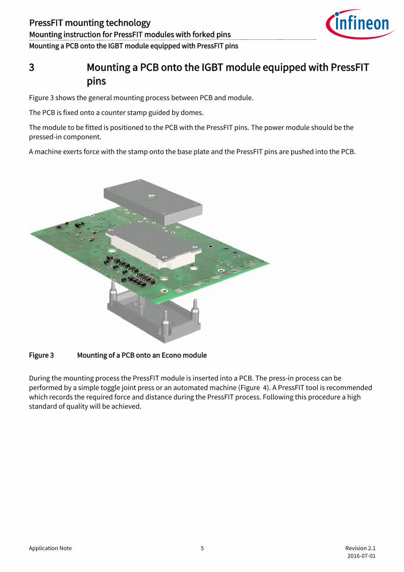
Figure 3 shows the general mounting process between PCB and module.
The PCB is fixed onto a counter stamp guided by domes.
The module to be fitted is positioned to the PCB with the PressFIT pins. The power module should be the pressed-in component.
A machine exerts force with the stamp onto the base plate and the PressFIT pins are pushed into the PCB.
Figure 3 Mounting of a PCB onto an Econo module
During the mounting process the PressFIT module is inserted into a PCB. The press-in process can be
performed by a simple toggle joint press or an automated machine (Figure 4). A PressFIT tool is recommended which records the required force and distance during the PressFIT process. Following this procedure a high standard of quality will be achieved.
Application Note 6 Revision 2.1
2016-07-01
PressFIT mounting technology Mounting instruction for PressFIT modules with forked pins
Mounting a PCB onto the IGBT module equipped with PressFIT pins
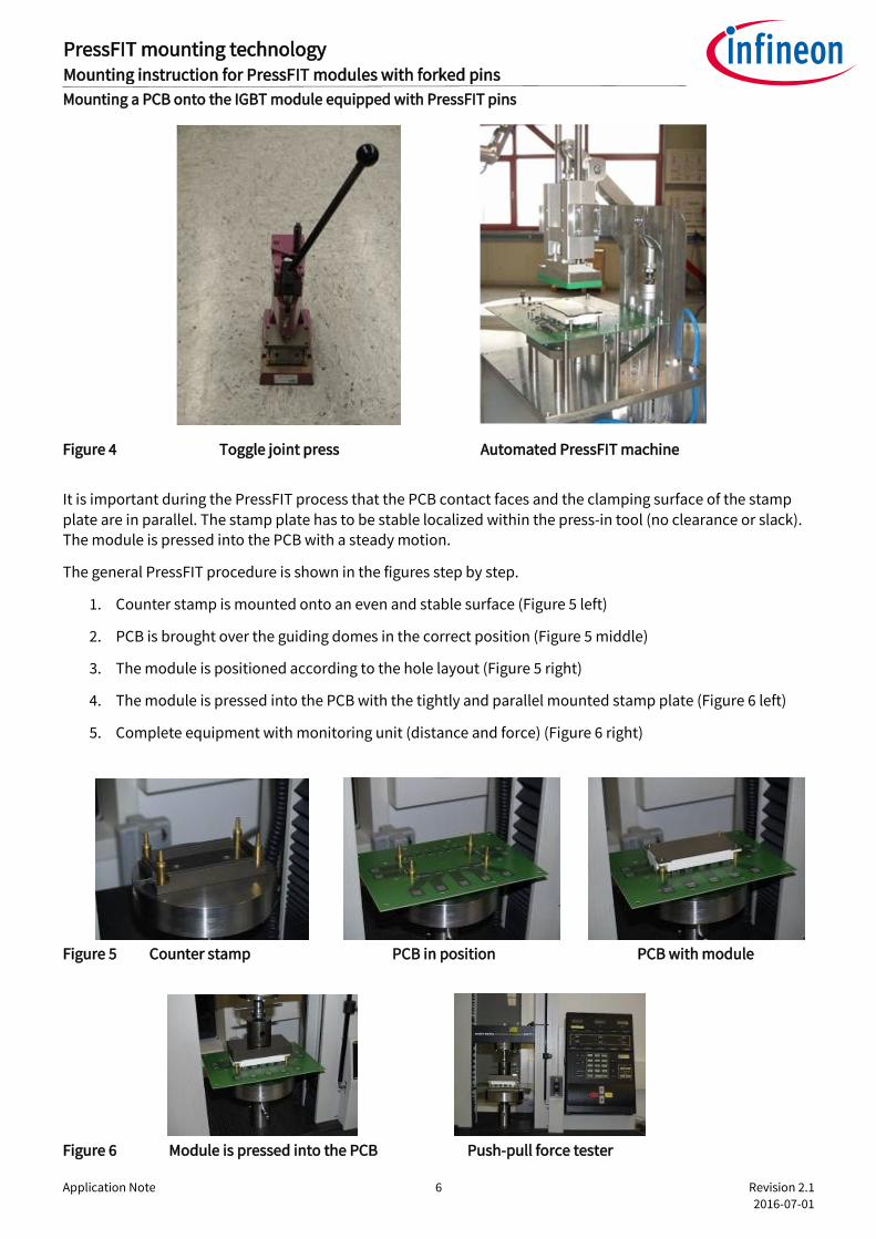
Figure 4 Toggle joint press Automated PressFIT machine
It is important during the PressFIT process that the PCB contact faces and the clamping surface of the stamp
plate are in parallel. The stamp plate has to be stable localized within the press-in tool (no clearance or slack). The module is pressed into the PCB with a steady motion.
The general PressFIT procedure is shown in the figures step by step.
1. Counter stamp is mounted onto an even and stable surface (Figure 5 left)
2. PCB is brought over the guiding domes in the correct position (Figure 5 middle)
3. The module is positioned according to the hole layout (Figure 5 right)
4. The module is pressed into the PCB with the tightly and parallel mounted stamp plate (Figure 6 left)
5. Complete equipment with monitoring unit (distance and force) (Figure 6 right)
Figure 5 Counter stamp PCB in position PCB with module
Figure 6 Module is pressed into the PCB Push-pull force tester
Application Note 7 Revision 2.1
2016-07-01
PressFIT mounting technology Mounting instruction for PressFIT modules with forked pins
Mounting a PCB onto the IGBT module equipped with PressFIT pins
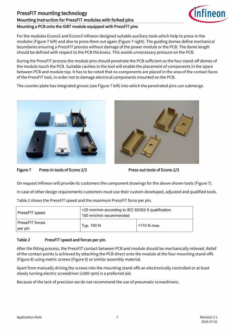
For the modules Econo2 and Econo3 Infineon designed suitable auxiliary tools which help to press-in the modules (Figure 7 left) and also to press them out again (Figure 7 right). The guiding domes define mechanical
boundaries ensuring a PressFIT process without damage of the power module or the PCB. The dome length should be defined with respect to the PCB thickness. This avoids unnecessary pressure on the PCB.
During the PressFIT process the module pins should penetrate the PCB sufficient so the four stand-off domes of
the module touch the PCB. Suitable cavities in the tool will enable the placement of components in the space between PCB and module top. It has to be noted that no components are placed in the area of the contact faces of the PressFIT tool, in order not to damage electrical components mounted on the PCB.
The counter plate has integrated groves (see Figure 7 left) into which the penetrated pins can submerge.
Figure 7 Press-in tools of Econo 2/3 Press-out tools of Econo 2/3
On request Infineon will provide its customers the component drawings for the above shown tools (Figure 7).
In case of other design requirements customers must use their custom developed, adjusted and qualified tools.
Table 2 shows the PressFIT speed and the maximum PressFIT force per pin.
PressFIT speed >25 mm/min according to IEC 60352-5 qualification
100 mm/min recommended
PressFIT forces
per pin Typ. 100 N <110 N max.
Table 2 PressFIT speed and forces per pin.
After the fitting process, the PressFIT contact between PCB and module should be mechanically relieved. Relief of the contact points is achieved by attaching the PCB direct onto the module at the four mounting stand-offs (Figure 8) using metric screws (Figure 9) or similar assembly material.
Apart from manually driving the screws into the mounting stand-offs an electronically controlled or at least slowly turning electric screwdriver (≤300 rpm) is a preferred aid.
Because of the lack of precision we do not recommend the use of pneumatic screwdrivers.

Application Note 8 Revision 2.1
2016-07-01
PressFIT mounting technology Mounting instruction for PressFIT modules with forked pins
Mounting a PCB onto the IGBT module equipped with PressFIT pins
Econo2 Econo3
Figure 8 Figure 14 PCB mounting stand-offs of an EconoPACK™ module
The effective length of the screw thread entering the mounting stand-off should be of a minimum length of lmin≥4 mm and a maximum length of lmax≤10 mm giving consideration to the PCB thickness and the weight of the driver PCB.
The initial 1.5 mm of the mounting stand-off serve as guidance only and cannot take any force. The thread in the plastics will form itself by driving in the screws. Metric screws M2.5*X can be used for mounting a PCB e.g. M2.5*8 or M2.5*10 dependent on the used PCB thickness.
To avoid damage or splitting of the stand-off, straight insertion of the screw into the stand-off has to be observed during assembly.
A. Correctly assembled screw B. Incorrectly assembled screw
Figure 9 (Left) Correctly assembled screw into the mounting stand-off. (Right) Incorrectly positioned screw
in the mounting stand-off
The recommended screws are based on laboratory tests. Depending on screws and tools used it may be necessary to adapt the assembly process accordingly.
1
4 2
3 1 3
4 2
screw
module module
screw

Application Note 9 Revision 2.1
2016-07-01
PressFIT mounting technology Mounting instruction for PressFIT modules with forked pins
Mounting a PCB onto the IGBT module equipped with PressFIT pins
3.1 Pressing-in several modules at the same time
The press-in of more than one module at the same time increases the complexity of the press-in process.
The modules of the EconoPACK™ family have a height of 17 mm +- 0.5 mm. Consequently a slight height variation between several modules on one PCB can occur. This leads to an unequal force-distance behavior between the modules during press-in.
That is the reason why we recommend defining a certain distance for the PressFIT process of several modules
at the same time. This leads to an equal height position of the modules base plates, which is necessary for a proper thermal connection of all modules after assembly on the heat sink.
As a slight pressure on the modules pins is better than pulling forces, the distance definition should not lead to
stronger pulling forces for modules at the lower edge of the possible height variation (16.5 mm) after assembly on the heat sink.
We recommend a defined distance for PressFIT of 17.0 mm.
Modules which are higher than 17.0 mm (maximum 17.5 mm) will experience a slight acceptable pressure by the use of this distance.

Application Note 10 Revision 2.1
2016-07-01
PressFIT mounting technology Mounting instruction for PressFIT modules with forked pins
Heat sink requirements
4 Heat sink requirements
The power loss occurring in the module has to be dissipated via a heat sink in order not to exceed the maximum permissible temperature specified in the datasheets during switching (Tvjop) in operation.
The condition of the heat sink surface in the area where the module is mounted is of great importance, as this
interface between heat sink and module is of decisive influence on the heat transfer of the entire system.
The contact surfaces, the base plate of the module and the surface of the heat sink have to be free of degradation and contamination and should be cleaned with a fresh, lint free cloth.
The contact surface of the heat sink should not exceed the following values
Surface flatness ≤50 µm
Surface roughness Rz≤10 µm
The heat sink has to be of sufficient stiffness for the assembly and the subsequent transport in order not to exert additional straining and/or pulling forces to the base plate of the module. During the entire assembly process the heat sink has to be handled twist free.

Application Note 11 Revision 2.1
2016-07-01
PressFIT mounting technology Mounting instruction for PressFIT modules with forked pins
Application of the thermal compound
5 Application of the thermal compound
Due to the individual surface shape of the module baseplate, the heat sink do not touch the entire baseplate area so that a certain local education gap between the two components cannot be avoided.
To dissipate the losses occurring in the module and to achieve a good heat flow into the heat sink, all localised
cavities have to be filled with thermal compound. When using thermal compounds a suitable application needs to be assured.
A well applied layer will fill all cavities and at the same time does not prevent the metallic contact between
base plate and heat sink surface. A compound should be selected which shows permanently elastic features in
order to assure a continuously favourable heat transfer resistance. The paste should be applied in a way that no screw holes are contaminated so that bolt torques are not degraded.
Common rollers or fine toothed spatulas can be used to apply the thermal compound. The layer thickness of the compound should typically be 50 µm to 100 µm on the base plate of the module.
The manual application of thermal compound with a constant layer thickness in the µm-region is problematic
of course. Generally the application is sufficient when after tightening the module a small quantity of surplus compound is squeezed out around the sides of the module (s. Fig. 10).
For qualification and verification of the assembly process the thermal values of the module should be checked in a training phase.
In addition, it is possible to check the layer thickness of the thermal compound after application with the aid of a toothed gauge.
As a guideline for the required amount of thermal compound for a homogenous layer thickness of 100 µm, a
volume of V=0.76 cm3 results for the Econo3 module with a base plate size of 62 mm*122 mm. A volume of V=0.48 cm3 results for the Econo2 module with a base plate size of 45 mm*107.5 mm These volumes can be measured with the aid of a syringe or applied from a tube.
Figure 10 Mounted EconoPIM™ module with thermal compound oozing out on the side
The application of thermal compound by a screen print process is recommended. Apart from an optimised and
module specific distribution of thermal compound, an optimised and reproducible layer thickness application is achievable with this procedure.
Further notes regarding the use of screen print templates for the application of thermal compound can be found in the application note “AN2006-02 Application of screen print templates”.

Application Note 12 Revision 2.1
2016-07-01
PressFIT mounting technology Mounting instruction for PressFIT modules with forked pins
Application of the thermal compound
5.1 Press-In process with TIM Modules
If modules with pre-applied thermal interface material (TIM) are used, the press-in stamp has to be designed
with respect to the position of the TIM material on the modules base plate. Figure 11 shows the base plates of Econo2 and Econo3 modules with TIM.
Figure 11 Econo 2 (left) and Econo 3 (right) bottom view with TIM.
The structure of the presented TIM surfaces is only exemplary and not fixed for all products within the EconoPACKTM family.
The stamp should not touch the TIM material during press-in. That is the reason why the stamp touches only
the base plate areas without TIM. Figure 12 shows the geometries of the stamp for the press-in of EconoPACKTM modules with TIM
Figure 12 PressFIT stamp for Econo 2 (left) and Econo 3 (right) with TIM.

Application Note 13 Revision 2.1
2016-07-01
PressFIT mounting technology Mounting instruction for PressFIT modules with forked pins
Bolts to mount modules to the heatsink
6 Bolts to mount modules to the heatsink
To mount the modules the following is recommended to use: DIN M5 bolts which comply at least with class 6.8, for example, according to DIN 912 (ISO4762), ISO 7380, DIN 6912, DIN 7984 in combination with a suitable washer and spring washer, for example, according to DIN 433 or DIN 125 or complete combination bolts.
The clearance and creepage distances specified in the Econo datasheets are the shortest clearance and creepage distances existing for the unassembled and unconnected module.
When selecting suitable M5 bolts, washers and spring washers to mount the modules, it is recommended to
consider the resulting clearance and creepage distances between the power terminal and the nearest bolt head or washer during the development phase and according to the valid standards.

Application Note 14 Revision 2.1
2016-07-01
PressFIT mounting technology Mounting instruction for PressFIT modules with forked pins
Mounting modules to the heatsink
7 Mounting modules to the heatsink
Mounting the module has to occur within the permissible module tolerances. Further information and drawings regarding the modules are given in the relevant datasheets.
The clamping force of the module to the heat sink resulting from the assembly process depends on the
torque applied and the condition of the heat sink material. The following torque values specified in the datasheet result from steel bolts in aluminium heat sinks with a dry M5 thread and their typical friction factors of µG=0.2…µG=0.25 (µG=friction coefficient thread in heat sink):
Mmin=3 Nm to Mmax=6 Nm.
The module fastening bolts are to be tightened uniformly in the recommended sequences with the specified torque.
Other material combinations of bolts and/or heat sink material may require an adaptation of the mechanical parameters.
For a good thermal contact to the heat sink the following procedure is recommended when tightening the four M5 fastening bolts.
1. Place the module with the thermal compound applied onto the heat sink and fix with two bolts by the Econo2 and four bolts by the Econo3 module.
2. Fix the bolts with 0.5 Nm (hand tight) by the Econo2 and 3 (crosswise by the Econo3) in the following sequence
Bolt number 1 – 2 (Econo2 )
Bolt number 1 – 2 – 3 – 4 (Econo3 )
3. Tighten the bolts with 3Nm – 6Nm in the same sequence (crosswise by the Econo3 )
Bolt number 1 – 2 (Econo2 )
Bolt number 1 – 2 – 3 – 4 (Econo3 )
Depending on the viscosity of the thermal compound used an intermediate step 2.a may be required for high
viscosity. This will give the thermal compound the chance to flow during the assembly process to the heat sink
and adapt to the module base plate and heat sink shape. After a certain pause time, depending on the thermal
compound used, step 3 has to be carried out.
2.a Tighten the bolts with approx. 2Nm in the same sequence (crosswise by the Econo3)
Bolt number 1 – 2 (Econo2 )
Bolt number 1 – 2 – 3 – 4 (Econo3 )

Application Note 15 Revision 2.1
2016-07-01
PressFIT mounting technology Mounting instruction for PressFIT modules with forked pins
Mounting modules to the heatsink
Econo2 Econo3
Figure 13 Tightening sequence to mount the module
When using thermal compound, it may be necessary depending on the type of paste to check the tightening
torques of the fastening bolts for the correct value after a heat-up test. When using thermal pads instead of
thermal compound, it is recommended to definitely perform this additional check. The torques given in application notes are valid when using thermal compound. Own tests and measurements with the thermal pads envisaged are absolutely necessary!
When selecting the thermal compound or thermal pads, the thermal contact and long-term stability should be considered and discussed with the manufacturer.
1 3
2 4
1
2

Application Note 16 Revision 2.1
2016-07-01
PressFIT mounting technology Mounting instruction for PressFIT modules with forked pins
Storage/application and transport of IGBT modules
8 Storage/application and transport of IGBT modules
During transport and storage of the modules extreme forces through shock or vibration have to be avoided as well as extreme environmental influences.
Storage of the modules at the limits of the temperature specified in the datasheet is not recommended.
The recommended storage conditions according to Application Note TR14 should be assured for the recommended storage time of max. two years.
Max. air temperature: Tmax air=+40°C
Min. air temperature: Tmin air=+5°C
Max. relative humidity: φmax=75%
Min. relative humidity: φmin=10%
Pre-drying of the case prior to the solder process as it is recommended for molded discrete components (e.g. microcontrollers, TO-cases etc.) is not required for PressFIT modules.
Econo modules are not hermetically sealed. The housings and the molding compound, used for the electrical
isolation within the housing, are permeable for humidity and gases in both directions. Therefore humidity
differences will be equalized in both directions.
Corrosive gases must be avoided during operation and storage of the devices. The climatic conditions for
Infineon Econo modules in active, current carrying operation are specified as per EN60721-3-3 class 3K3 for fixed installations. The operation of the modules in humid atmosphere caused by condensation and/or the operation in climatic
conditions beyond class 3K3 of EN60721-3-3 must be avoided and additional countermeasures need to be taken in such cases.
Generally, condensation, precipitation, icing and corrosive gases in operation, storage and during
transportation are not allowed.

Application Note 17 Revision 2.1
2016-07-01
PressFIT mounting technology Mounting instruction for PressFIT modules with forked pins
Disassembly
9 Disassembly
The disassembly of the fitted module can be done with the appropriate auxiliary tools (s. Fig. 14). The PCB is
placed into the corresponding device (tray) together with the fitted module (s. Fig. 15). The press-out stamp is then used to exert a force onto the pins protruding through the PCB. The tools must be parallel to each other in order not to damage the individual components such as PCB and module. The module falls into the tray and is separated from the PCB. The layout of the PCB needs to take the dimensions of the press-out tool into
consideration in order not to damage the components surrounding the module or in the space between lid and PCB.
Figure 14 Press-out tools of Econo2/3 module
Press-out jig Positioning the PCB with module Pressing-out the module
Figure 15 Press-out procedure of Econo3 module
The press-out force can be used to qualify the PressFIT process. The maximum press-out force should be higher than 40 N after a storage of more than 72 hours (at room temperature) to ensure a good cold-welding interface.

Application Note 18 Revision 2.1
2016-07-01
Revision History
PressFIT mounting technology Mounting instruction for PressFIT modules with forked pins
Revision History
Major changes since the last revision
Page or Reference Description of change
Chapter 3.1 Additional recommendation for press in of several modules
Trademarks of Infineon Technologies AG µHVIC™, µIPM™, µPFC™, AU-ConvertIR™, AURIX™, C166™, CanPAK™, CIPOS™, CIPURSE™, CoolDP™, CoolGaN™, COOLiR™, CoolMOS™, CoolSET™, CoolSiC™, DAVE™, DI-POL™, DirectFET™, DrBlade™, EasyPIM™, EconoBRIDGE™, EconoDUAL™, EconoPACK™, EconoPIM™, EiceDRIVER™, eupec™, FCOS™, GaNpowIR™, HEXFET™, HITFET™, HybridPACK™, iMOTION™, IRAM™, ISOFACE™, IsoPACK™, LEDrivIR™, LITIX™, MIPAQ™, ModSTACK™, my-d™, NovalithIC™, OPTIGA™, OptiMOS™, ORIGA™, PowIRaudio™, PowIRStage™, PrimePACK™, PrimeSTACK™, PROFET™, PRO-SIL™, RASIC™, REAL3™, SmartLEWIS™, SOLID FLASH™, SPOC™, StrongIRFET™, SupIRBuck™, TEMPFET™, TRENCHSTOP™, TriCore™, UHVIC™, XHP™, XMC™ Trademarks updated November 2015
Other Trademarks All referenced product or service names and trademarks are the property of their respective owners. AN2007-09owners.
Edition 2016-07-01
AN2007-09
Published by
Infineon Technologies AG
81726 Munich, Germany
© 2016 Infineon Technologies AG.
All Rights Reserved.
Do you have a question about this document?
Email: [email protected]
Document reference
IMPORTANT NOTICE The information contained in this application note is given as a hint for the implementation of the product only and shall in no event be regarded as a description or warranty of a certain functionality, condition or quality of the product. Before implementation of the product, the recipient of this application note must verify any function and other technical information given herein in the real application. Infineon Technologies hereby disclaims any and all warranties and liabilities of any kind (including without limitation warranties of non-infringement of intellectual property rights of any third party) with respect to any and all information given in this application note. The data contained in this document is exclusively intended for technically trained staff. It is the responsibility of customer’s technical departments to evaluate the suitability of the product for the intended application and the completeness of the product information given in this document with respect to such application.
For further information on the product, technology, delivery terms and conditions and prices please contact your nearest Infineon Technologies office (www.infineon.com). Please note that this product is not qualified according to the AEC Q100 or AEC Q101 documents of the Automotive Electronics Council.
WARNINGS Due to technical requirements products may contain dangerous substances. For information on the types in question please contact your nearest Infineon Technologies office. Except as otherwise explicitly approved by Infineon Technologies in a written document signed by authorized representatives of Infineon Technologies, Infineon Technologies’ products may not be used in any applications where a failure of the product or any consequences of the use thereof can reasonably be expected to result in personal injury.