
Native Vegetation Clearance Proposal Northern PowerStation ...
AE50TAH 3/19/15
OWNER'S MANUAL
AE50TAH
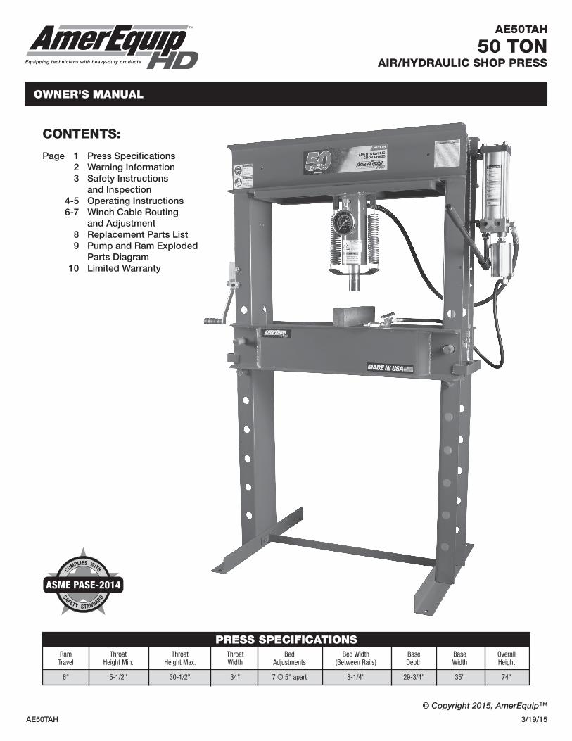
50 TONAIR/HYDRAULIC SHOP PRESS
CONTENTS:
Page 1 Press Specifications 2 Warning Information 3 Safety Instructions and Inspection 4-5 Operating Instructions 6-7 Winch Cable Routing and Adjustment 8 Replacement Parts List 9 Pump and Ram Exploded Parts Diagram 10 Limited Warranty
© Copyright 2015, AmerEquip™
TM
Equipping technicians with heavy-duty products
Ram Throat Throat Throat Bed Bed Width Base Base Overall Travel Height Min. Height Max. Width Adjustments (Between Rails) Depth Width Height
6" 5-1/2" 30-1/2" 34" 7 @ 5" apart 8-1/4" 29-3/4" 35" 74"
PRESS SPECIFICATIONS
SAFETY STANDARD
COMPLIES WITH
ASME PASE-2014

AE50TAH 2 3/19/15
WARNINg INfORmATION
This is the safety alert symbol. It is used to alert you to potential personal injury hazards. Obey all safety messages that follow this symbol to avoid possible injury or death.
IMPORTANT: READ THESE INSTRUCTIONS BEFORE OPERATING
BEFORE USING THIS DEVICE, READ THIS MANUAL COMPLETELY AND THOROUGHLY. UNDERSTAND ITS OPERATING PROCEDURES, SAFETY WARNINGS AND MAINTENANCE REQUIREMENTS.
It is the responsibility of the owner to make sure all personnel read this manual prior to using the device. It is also the responsibility of the device owner to keep this manual intact and in a convenient location for all to see and read. If the manual or product labels are lost or not legible, contact AmerEquip™ for replacements. If the operator is not fluent in English, the product and safety instructions shall be read to and discussed with the operator in the operator's native language by the purchaser/owner or his designee, making sure that the operator comprehends its contents.
THE NATURE OF HAZARDOUS SITUATIONS
The use of shop presses and their accessories is subject to certain hazards that cannot be prevented by mechanical means, but only by the exercise of intelligence, care, and common sense. It is therefore essential to have owners and personnel involved in the use and operation of the equipment who are careful, competent, trained, and qualified in the safe operation of the equipment and its proper use. Examples of hazards are components being pressed and breaking resulting in flying parts that are not secured from hitting the operator, the set up in the press is not secure, guards, shields or protective blankets are not used, improperly securing adjustments on the press, overloading and off-center loads.
METHODS TO AVOID HAZARDOUS SITUATIONS
• Read,study,understandandfollowallinstructionsbeforeoperatingthispress. • Priortousemakesurethepressissecurelyanchoredtoaconcretefloor,installedandoperatedinaccordancewithOSHA,state and local safety standards. • Visualinspectionofthepressshouldbemadebeforeuse,checkingforsignsofcrackedwelds,bentbedpins,looseormissing bolts, leaks, or any other structural damage. Corrections must be made before using the press. • Noalterationsshallbemadetothispress. • OperatorsandobserversshallweareyeprotectionthatmeetsANSIZ87.1andOSHAStandards. • Partsbeingpressedmaysplinter,shatter,orbeejectedfromthepressatadangerousrateofspeed.Duetoavarietyofpress applications, it is the press owner’s responsibility to provide adequate guards, eye protection and protective clothing to the press operator. • Alwaysuseabearingshieldwhenpressingbearings. • Keephands,arms,feet,andlegsoutofworkarea.Accidentalslippagecanresultinpersonalinjury. • Removeallloadsfrommovablebolsterbeforeadjustingbolsterheight.Bewareoffallingbolster. • Pressonlyonloadssupportedbymovablebolsterandpressplates.Donotsupportloadsonfloororpressframelegs. • Whenusinganyaccessoriessuchaspressorarborplates,becertaintheyarecenteredonthemovablebolsterandinfullcontact with both sides of the bolster. • Usecautionwhenpositioningworktobepressedtoensuretheitemtobepressedcannotbeejectedatadangerousrateofspeed. • Avoidoff-centerloads.Donotusespacersorextendersbetweenthepressramplungerandtheitembeingpressed.Ifthereisnot enough ram stroke, adjust the height of the movable bolster. • Beforeapplyingload,becertainallmovablebolstersupportingpinsarefullyengaged.Makesuremovablebolsterliftcables(if equipped) are slack before pressing on bolster. • Donotexceedtheratedcapacity.Whenattachmentsandadaptersareused,theratedcapacityofthesystemshallbenogreater than the rated capacity of the lowest-rated component or combination of components that make up the system. • Alwaysuseanaccurateforcegaugetomeasurepressingforce. • Donottamperwiththepressload-limitingdevicesettings. • Donotgonearleaks.Highpressurehydraulicfluidcanpunctureskinandcauseseriousinjury,gangrene,ordeath.Donotuse finger or skin to check for leaks. If injured, seek emergency medical help as immediate surgery is required to remove the fluid. • Releasehydraulicpressurebeforelooseninganyfittings. • Maintainproperhydraulicfluidlevels. • ThisproductmaycontainoneormorechemicalsknowntotheStateofCaliforniatocausecancerandbirthdefectsorother reproductive harm. Wash hands thoroughly after handling. • Failuretounderstandandheedthesemarkingsmayresultinseriousorfatalpersonalinjuryand/orpropertydamage.
WARNING: Indicates a hazardous situation which, if not avoided, could result in death or serious injury.
WARNING
WARNING
WARNING

AE50TAH 3 3/19/15
CONSEQUENCES OF NOT AVOIDING HAZARDOUS SITUATIONS
Failure to read this manual completely and thoroughly, failure to understand its OPERATING INSTRUCTIONS, SAFETY WARNINGS, MAINTENANCEINSTRUCTIONSandcomplywiththem,andfailuretocomplywiththeMETHODSTOAVOIDHAZARDOUS SITUATIONS could cause accidents resulting in serious or fatal personal injury and/or property damage.
WARNINg INfORmATION (CONTINUED)
AE50TAH
50 TONAIR/HYDRAULIC SHOP PRESS
TM
Equipping technicians with heavy-duty products
WARNING
SAFETY INSTRUCTIONS• CHECKYOURLOCAL,STATEANDFEDERALREGULATIONSREGARDINGTHESAFEUSEOFTHISEQUIPMENT.• Yoursafetyistoppriority.Pleasehandleequipmentwithcare.• Fullyretractunitandremoveallitemsfromthepressbedframe.• Supportthepressbed,andremovethepins.• Raiseorlowerbedtodesiredheightandreinstallpresspins.Becertainpinsarefullyengagedintheparallelflangesoftheuprightcolumns.• Positionpressonaflat,level,hardsurface,preferablyconcrete. Make sure all nuts and bolts are tight.• Cleartheareaofbystanders,especiallysmallchildren,beforeusing.• Setthepressbedtotherequiredheight.Thepressismosteffective when the work piece is located 1 inch below the ram’s retracted position. The compression stroke can include the entire 5" working range. • Thepressisdesignedtoexertaforceonanythingwhichispositionedbeneathitsram.Theworkpiececanpopoutfromundertheramat a high rate of speed and injure someone.• PressingBearings:Itisessentialthatyouusethebearingshieldwhenpressingbearingsonoroff.
INSPECTIONVisual inspection of the shop press should be made before each use of the press, checking for damaged, loose or missing parts. Each press must be inspected by an authorized sevice center immediately if subjected to an abnormal load or shock. Any press which appears to be damaged in any way, is found to be badly worn, or operated abnormally must be prevented from being used until necessary repairs are made by an authorized service center. It is recommended that an annual inspection of the press be made by an authorized service center and that any defective parts, missing or damaged warning labels be replaced with AmerEquip™ parts and labels.
SAfETY INSTRUCTIONS AND INSPECTION
AE50TAH 4 3/19/15
AE50TAH
50 TONAIR/HYDRAULIC SHOP PRESS
TM
Equipping technicians with heavy-duty products
OPERATING INSTRUCTIONS
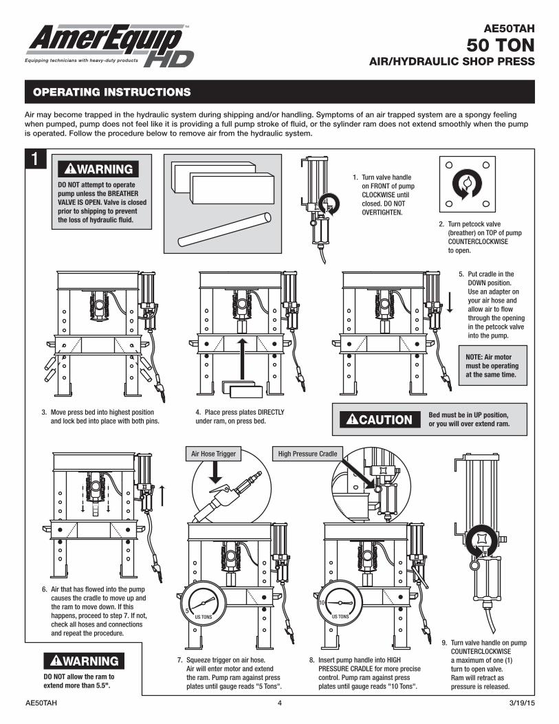
Air may become trapped in the hydraulic system during shipping and/or handling. Symptoms of an air trapped system are a spongy feeling when pumped, pump does not feel like it is providing a full pump stroke of fluid, or the sylinder ram does not extend smoothly when the pump is operated. Follow the procedure below to remove air from the hydraulic system.
1
US TONSUS TONS
WARNING
CAUTION
DO NOT allow the ram to extend more than 5.5".
Bed must be in UP position, or you will over extend ram.
NOTE: Air motor must be operating at the same time.
1. Turn valve handle on FRONT of pump CLOCKWISE until closed. DO NOT OVERTIGHTEN.
3. Move press bed into highest position and lock bed into place with both pins.
6. Air that has flowed into the pump causes the cradle to move up and the ram to move down. If this happens, proceed to step 7. If not, check all hoses and connections and repeat the procedure.
7. Squeeze trigger on air hose. Air will enter motor and extend the ram. Pump ram against press plates until gauge reads "5 Tons".
8. Insert pump handle into HIGH PRESSURE CRADLE for more precise control. Pump ram against press plates until gauge reads "10 Tons".
9. Turn valve handle on pump COUNTERCLOCKWISE a maximum of one (1) turn to open valve. Ram will retract as pressure is released.
4. Place press plates DIRECTLY under ram, on press bed.
Air Hose Trigger High Pressure Cradle
2. Turn petcock valve (breather) on TOP of pump COUNTERCLOCKWISE to open.
5. Put cradle in the DOWN position. Use an adapter on your air hose and allow air to flow through the opening in the petcock valve into the pump.
WARNINGDO NOT attempt to operate pump unless the BREATHER VALVE IS OPEN. Valve is closed prior to shipping to prevent the loss of hydraulic fluid.

AE50TAH 5 3/19/15
2
OPERATINg INSTRUCTIONS (CONTINUED)
AE50TAH
50 TONAIR/HYDRAULIC SHOP PRESS
TM
Equipping technicians with heavy-duty products
WARNING
WARNING
Failure to heed these warnings may result in loss of load, damage to the press and/or failure resulting in property damage, personal or fatal injury. This operating manual contains important details concerning the safe operation of this press. The user must read and understand these details before any use of the press.
This manual must be retained for future reference.
This symbol alerts you to the possibility of serious injury or death if instructions are not followed.
DO NOT attempt to operate pump unless the BREATHER VALVE IS OPEN. Valve is closed prior to shipping to prevent the loss of hydraulic fluid.
1. BEFORE OPERATING PUMP, open petcock valve (breather) located on TOP of pump assembly by turning COUNTERCLOCKWISE.
3. Squeeze air hose trigger until ram comes into contact with item to be pressed.
4. Once ram is in contact with the item to be pressed, insert pump handle into high pressure cradle. Using the high pressure pump moves the ram less with each stroke and requires less effort to apply pressure.
2. CLOSE the valve located on the FRONT of the pump assembly by turning CLOCKWISE. Connect using a 3/8" line. Do not exceed air pressure of 90-120 psig.
Top view of pump
CAUTIONHAND TIGHTEN VALVE ONLY. Excess pressure could damage the valve assembly.
Air Hose Trigger High Pressure Cradle
CAUTIONDO NOT TURN RELEASE VALVE MORE THAN ONE FULL TURN or equipment may be disabled.

AE50TAH 6 3/19/15
3
WINCH CABLE ROUTING AND ADJUSTMENT
AE50TAH
50 TONAIR/HYDRAULIC SHOP PRESS
TM
Equipping technicians with heavy-duty products
Dark Gray - Long CableRight side of press,
under pump assemblyRight side of press
Light Gray - Short Cable
1. Move press bed into LOWEST position so it is resting on top of pins 1 and 2.
3. Thread the BARE end of the LONGER of the two steel cables up and through the pump bracket.
2. Install pre-attached eye bolt on LONGER cable to press bed handle located under pump assembly. DO NOT FULLY TIGHTEN. Center with side of press bed and make sure there is enough room to lower or raise both nuts on eye bolt for precise alignment.
WARNINGDO NOT FULLY TIGHTEN
4. Run the long cable up and OVER BOTH ROLLER BRACKETS and feed into winch. Be sure to thread 12 inches (1 foot) of extra cable through winch.
5. Once winch cable has been threaded, pull excess cable back through winch as shown in diagram above. The cable should be locked tightly around itself with no excess cable left hanging. Operate winch enough to remove slack from longer cable.
6. Mount winch to frame using the provided washers, 1/2" nuts and 1/2"-13 x 1-1/2" bolts.
This end feeds into winch
LONG CABLE top view of press
WARNINGMount winch to frameAFTER threading cable.
Note: Refer to manual from winch manufacturer for detailed instructions on winch assembly and cable threading procedure.
AE50TAH 7 3/19/15
WINCH CABLE ROUTING AND ADJUSTMENT (CONTINUED)
AE50TAH
50 TONAIR/HYDRAULIC SHOP PRESS
TM
Equipping technicians with heavy-duty products
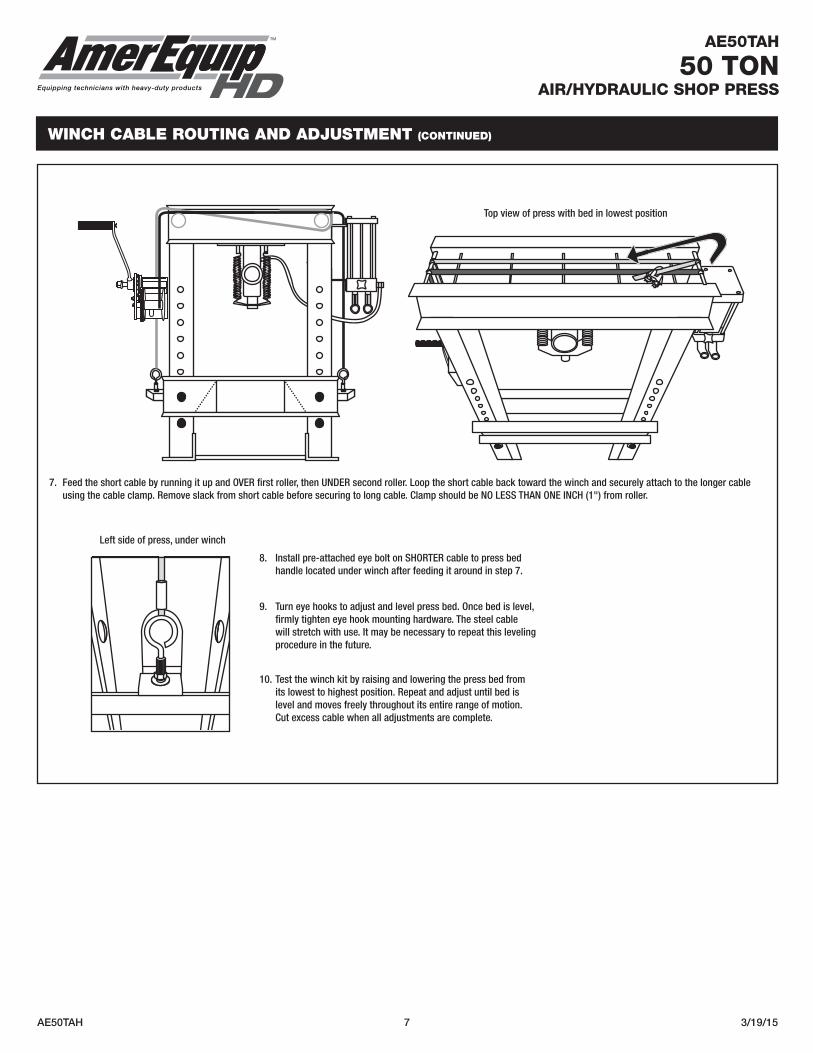
8. Install pre-attached eye bolt on SHORTER cable to press bed handle located under winch after feeding it around in step 7.
9. Turn eye hooks to adjust and level press bed. Once bed is level, firmly tighten eye hook mounting hardware. The steel cable will stretch with use. It may be necessary to repeat this leveling procedure in the future.
10. Test the winch kit by raising and lowering the press bed from its lowest to highest position. Repeat and adjust until bed is level and moves freely throughout its entire range of motion. Cut excess cable when all adjustments are complete.
7. Feed the short cable by running it up and OVER first roller, then UNDER second roller. Loop the short cable back toward the winch and securely attach to the longer cable using the cable clamp. Remove slack from short cable before securing to long cable. Clamp should be NO LESS THAN ONE INCH (1") from roller.
Top view of press with bed in lowest position
Left side of press, under winch

AE50TAH 8 3/19/15
19
12
15
8
2
1
14
13
3
4
55
18
11
10
55
10
9
8
6
7
20
17
REPLACEMENT PARTS LIST
AE50TAH
50 TONAIR/HYDRAULIC SHOP PRESS
TM
Equipping technicians with heavy-duty products
Air/Hydraulic Shop Press with Winch
ITEM NO. ITEM NO. DESCRIPTION QTY. 1 RSCBP1214 Ram Spring 2 2 Press Bed 1 3 Press Frame 1 4 Ram Frame 1 5 RSCBP1225 Press Pin 4 6 RS310012 Pushing Adapter 1 7 RSBS1 Bearing Shield 1 8 RSCBP1205 Press Plate 2 9 RSCBP1211 Press Feet 2 10 RSCBP1212 Z Bar 1 11 RSCBP1209 Pump Handle 1 12 RS50AOPAM Pump (with Air Motor) 1 13 RSCBP1202GG Ram (includes gauge) 1 14 RSCBP1206G Liquid Filled Gauge 1
ITEM NO. ITEM NO. DESCRIPTION QTY. 15 RSCBP1204 Hose and Fitting 1 16 RSCBP1217 Seal Kit for Pump and Ram (not shown) 1 17 RS40MPPHK Press Hardware Kit 1 set 1/2"-13 x 1-1/2" Hex Head Bolt 10 1/2" Nut 10 Washer 10 18 RSAAMO2 Air Motor (shown with pump) 1 19 RS4050WCH Winch 1 20 RSWHK Winch Hardware Kit 1 set Cable Clamp 1 1/2"-13 x 1-1/2" Hex Head Bolt 2 1/2" Nut 2 Washer 2 Short Cable (includes eye bolt) 1 Long Cable (includes eye bolt) 1
**Pump and Ram Assembly includes pump, ram, gauge and hose and fitting (item numbers: 12 -15)

AE50TAH 9 3/19/15
PUMP AND RAM EXPLODED PARTS DIAGRAM
AE50TAH
50 TONAIR/HYDRAULIC SHOP PRESS
TM
Equipping technicians with heavy-duty products
8.886"
9.113"
10
9
15
1
7
6
4
8
5
3
1111
1
14
13
12
3
2
7
21
17
30
16
1
2
28
14
1
25
2411
1327
10
31
32
6
20
4
23
28
25
241028
13
29
21
8
26 24
12 3
5
RAm ITEM NO. DESCRIPTION QTY. 1 Base Weldment 1 2 Plug 1 3 Polypak Seal (Parker) 2 4 1/2-13 x 2 Hex HD C-S GR 2 Zinc 1 5 Piston 1 6 O-Ring (Parker) 1 7 Rod 1 8 Retaining Ring Int. 3.5 NOM 1 9 Piston Guide 1 10 Retractor Plate 1 11 Spring 2 12 Fitting Gauge 1.75 1 13 Gauge 1 14 90˚ Elbow 1/4 NPTF to -6 JIC 1 15 Hose Hydraulic 41 1/2 LG 7/16-20 JICF 1
PUmP ITEM NO. DESCRIPTION QTY. 1 Tank 1 2 Tie Rod 4 3 Air Adapter 1 4 1/2" Piston Body 1 5 Air Motor 1 6 1/2" Piston 1 7 1/4" MNPT Pressure Plug 1 8 Pump Body 1 9 Pump Lid 1 10 Pump Bracket 2 11 Valve Assembly 1 12 Pivot Pin 2 13 5/16" Steel Ball 5 14 Brass Drain Cock 1 16 Hydraulic Hose 41-1/2" L 7/16-20 JICF 1 17 7/16-14 Fin Hex Nut Zinc 4 20 O-Ring 121 * 3-1/2" Seal 2 23 3-3/16" Seal 1 24 SHCS 7/16 14 x 1/2" 4 25 SHCS 7/16 14 x 3/4" 4 26 Light Spring 2 27 Heavy Spring 2 28 7/16" Split Lock Washer 6 29 Pump Filter 1 30 Pump Fitting 1/4" MNPT 7/16" JICF 1 31 7/8" Grip 1 32 Handle for Pump 1 33 O-Ring 1
*
*
*
**
**
**
*
See Replacement Parts List for parts available separately.Parts with (*) are only available in Seal Kit, part number RSCBP1217. Individual parts pictured are components of the Seal Kit, RSCBP1217.
# 6 (Ram)QTY: 1
# 19 (Pump)QTY: 1
# 33 (Pump)(O-Ring for # 11 Valve Assembly on Pump)QTY: 1
# 20 (Pump)QTY: 1
# 22 (Pump)QTY: 1
# 26 (Pump)QTY: 2
# 3 (Ram)(Poly Pak - Note: Only the upper seal normally needs replacement)QTY: 1
# 21 (Pump)QTY: 2
# 13 (Pump)QTY: 5
# 23 (Pump)QTY: 1
# 27 (Pump)QTY: 2

AE50TAH 10 3/19/15
LIMITED WARRANTY
AE50TAH
50 TONAIR/HYDRAULIC SHOP PRESS
TM
Equipping technicians with heavy-duty products
AMEREQUIP™ WARRANTS TO ITS CUSTOMERS THAT THE COMPANY’S AMEREQUIP™ BRANDED PRODUCTS ARE FREE FROM DEFECTS IN WORKMANSHIP AND MATERIALS. AmerEquip™ will repair or replace its AmerEquip™ branded products which fail to give satisfactory service due to defective workmanship or materials, based upon the terms and conditions of the following described warranty plans attributed to that specific product.
This product carries a TWO-YEAR warranty. During this warranty period, AmerEquip™ will repair or replace at our option any part or unit which proves to be defective in material or workmanship.
Other important warranty informationThis warranty does not cover damage to equipment or tools arising from alteration, abuse, misuse, damage and does not cover any repairs or replacement made by anyone other than AmerEquip™ or its authorized warranty service centers. The foregoing obligation is AmerEquip's sole liability under this or any implied warranty and under no circumstances shall we be liable for any incidental or consequential damages.
NOTE: Some states do not allow the exclusion or limitation of incidental or consequential damages, so the above limitation or exclusion may not apply to you.
Return equipment or parts to an authorized service center, transportation prepaid. Be certain to include your name and address, evidence of the purchase date, and description of the suspected defect. If you have any questions about warranty service, please write to AmerEquip™. This warranty gives you specific legal rights and you may also have other rights which vary from state to state.
Repair kits and replacement parts are available for many of AmerEquip™ products regardless of whether or not the product is still covered by a warranty plan.
SHIPPING ADDRESS:AmerEquip™315 Hawkins Rd.Travelers Rest, South Carolina 29690
MAILING ADDRESS:AmerEquip™P.O. Box 1233Travelers Rest, South Carolina 29690


