President Air Motors - Find...
28
306–982 Rev. Z Supersedes Rev . Y First choice when quality counts.t INSTRUCTIONS-PARTS LIST INSTRUCTIONS This manual contains important warnings and information. READ AND KEEP FOR REFERENCE. PresidentR Air Motors See your pump instruction manual for Maximum Working Pressure. Model 205–647, Series L For in-line mounting, medium-pressure oil pump Model 206–078, Series L For in-line mounting, high-pressure grease pump Model 205–038, Series M For stanchion tube mounting Model 207–352, Series F For divorced mounting Model 222–772, Series F For divorced mounting Table of Contents Warnings 2 . . . . . . . . . . . . . . . . . . . . . . . . . . . . . . . . . . . . . . Installation 5 . . . . . . . . . . . . . . . . . . . . . . . . . . . . . . . . . . . . Operation 7 . . . . . . . . . . . . . . . . . . . . . . . . . . . . . . . . . . . . . Service 8 . . . . . . . . . . . . . . . . . . . . . . . . . . . . . . . . . . . . . . . Parts Drawings and Parts LIsts Model 205–647 14 . . . . . . . . . . . . . . . . . . . . . . . . . . . . . Model 206–078 16 . . . . . . . . . . . . . . . . . . . . . . . . . . . . . Model 205–038 18 . . . . . . . . . . . . . . . . . . . . . . . . . . . . . Model 207–352 20 . . . . . . . . . . . . . . . . . . . . . . . . . . . . . Model 222–772 22 . . . . . . . . . . . . . . . . . . . . . . . . . . . . . Accessories 24 . . . . . . . . . . . . . . . . . . . . . . . . . . . . . . . . . . Mounting Hole Layouts 25 . . . . . . . . . . . . . . . . . . . . . . . . . Dimensional Drawing 25 . . . . . . . . . . . . . . . . . . . . . . . . . . Technical Data 26 . . . . . . . . . . . . . . . . . . . . . . . . . . . . . . . . Graco Standard Warranty 28 . . . . . . . . . . . . . . . . . . . . . . Graco Phone Number 28 . . . . . . . . . . . . . . . . . . . . . . . . . . Model 207–352 Shown GRACO INC. P.O. BOX 1441 MINNEAPOLIS, MN 55440–1441 http://www.graco.com ECOPYRIGHT 1997, GRACO INC. Graco Inc. is registered to I.S. EN ISO 9001
Transcript of President Air Motors - Find...

306–982Rev. Z
Supersedes Rev . YFirst choice whenquality counts.�
INSTRUCTIONS-PARTS LIST
INSTRUCTIONS
This manual contains importantwarnings and information.READ AND KEEP FOR REFERENCE.
President � Air MotorsSee your pump instruction manual for Maximum Working Pressure.
Model 205–647, Series LFor in-line mounting, medium-pressure oil pump
Model 206–078, Series LFor in-line mounting, high-pressure grease pump
Model 205–038, Series MFor stanchion tube mounting
Model 207–352, Series FFor divorced mounting
Model 222–772, Series FFor divorced mounting
Table of ContentsWarnings 2. . . . . . . . . . . . . . . . . . . . . . . . . . . . . . . . . . . . . . Installation 5. . . . . . . . . . . . . . . . . . . . . . . . . . . . . . . . . . . . Operation 7. . . . . . . . . . . . . . . . . . . . . . . . . . . . . . . . . . . . . Service 8. . . . . . . . . . . . . . . . . . . . . . . . . . . . . . . . . . . . . . . Parts Drawings and Parts LIsts
Model 205–647 14. . . . . . . . . . . . . . . . . . . . . . . . . . . . . Model 206–078 16. . . . . . . . . . . . . . . . . . . . . . . . . . . . . Model 205–038 18. . . . . . . . . . . . . . . . . . . . . . . . . . . . . Model 207–352 20. . . . . . . . . . . . . . . . . . . . . . . . . . . . . Model 222–772 22. . . . . . . . . . . . . . . . . . . . . . . . . . . . .
Accessories 24. . . . . . . . . . . . . . . . . . . . . . . . . . . . . . . . . . Mounting Hole Layouts 25. . . . . . . . . . . . . . . . . . . . . . . . . Dimensional Drawing 25. . . . . . . . . . . . . . . . . . . . . . . . . . Technical Data 26. . . . . . . . . . . . . . . . . . . . . . . . . . . . . . . . Graco Standard Warranty 28. . . . . . . . . . . . . . . . . . . . . . Graco Phone Number 28. . . . . . . . . . . . . . . . . . . . . . . . . .
Model 207–352 Shown
GRACO INC. P.O. BOX 1441 MINNEAPOLIS, MN 55440–1441http://www.graco.com
�COPYRIGHT 1997, GRACO INC.Graco Inc. is registered to I.S. EN ISO 9001

� �������
SymbolsWarning Symbol
WARNINGThis symbol alerts you to the possibility of seriousinjury or death if you do not follow the instructions.
Caution Symbol
CAUTIONThis symbol alerts you to the possibility of damage toor destruction of equipment if you do not follow theinstructions.
WARNINGEQUIPMENT MISUSE HAZARD
Equipment misuse can cause the equipment to rupture or malfunction and result in serious injury.
� This equipment is for professional use only.
� Read all instruction manuals, tags, and labels before operating the equipment.
� Use the equipment only for its intended purpose. If you are not sure, call your Graco distributor.
� Do not alter or modify this equipment.
� Check equipment daily. Repair or replace worn or damaged parts immediately.
� Do not exceed the maximum working pressure stated on the equipment or in the Technical Datafor your equipment. Do not exceed the maximum working pressure of the lowest rated componentin your system.
� Use fluids and solvents which are compatible with the equipment wetted parts. Refer to the Tech-nical Data section of all equipment manuals. Read the fluid and solvent manufacturer’s warnings.
� Handle hoses carefully. Do not pull on hoses to move equipment.
� Route hoses away from traffic areas, sharp edges, moving parts, and hot surfaces. Do not exposeGraco hoses to temperatures above 66�C (150�F) or below –40�C (–40�F).
� Wear hearing protection when operating this equipment.
� Do not move or lift pressurized equipment.
� Comply with all applicable local, state, and national fire, electrical, and safety regulations.
� Never exceed 180 psi (1.2 MPa, 12 bar) air pressure to the motor, and never exceed the statedmaximum working pressure of the pump or the lowest rated component in your system. Refer toyour separate pump instruction manual.
� Be sure that all spray/dispensing equipment and accessories are rated to withstand the maximumair and fluid working pressures of this system. Do not exceed the maximum working pressure ofany component or accessory used in the system.

��������
WARNINGINJECTION HAZARD
Spray from the gun, leaks or ruptured components can inject fluid into your body and cause extremelyserious injury, including the need for amputation. Fluid splashed in the eyes or on the skin can alsocause serious injury.
� Fluid injected into the skin is a serious injury. The injury may look like just a cut, but it is a seriousinjury. Get immediate medical attention.
� Do not point the dispensing valve at anyone or any part of the body.
� Do not put your hand or fingers over the end of the dispensing valve.
� Do not stop or deflect leaks with your hand, body, glove or rag.
� Use only extensions and no-drip tips that are designed for use with your dispensing valve.
� Tighten all fluid connections before operating the equipment.
� Check the hoses, tubes, and couplings daily. Replace worn or damaged parts immediately. Do notrepair high pressure couplings; you must replace the entire hose.
MOVING PARTS HAZARD
Moving parts can pinch or amputate your fingers.
� Keep clear of all moving parts when starting or operating the pump.
� Before checking or servicing the equipment, follow the Pressure Relief Procedure on page 6 toprevent the equipment from starting unexpectedly.

� �������
WARNINGFIRE AND EXPLOSION HAZARD
Improper grounding, poor ventilation, open flames or sparks can cause a hazardous condition and re-sult in a fire or explosion and serious injury.
� Ground the equipment and the object being sprayed. Refer to Grounding on page 5.
� If there is any static sparking or you feel an electric shock while using this equipment, stop spray-ing immediately . Do not use the equipment until you identify and correct the problem.
� Provide fresh air ventilation to avoid the buildup of flammable fumes from solvents or the fluidbeing sprayed.
� Keep the spray area free of debris, including solvent, rags, and gasoline.
� Before operating this equipment, electrically disconnect all equipment in the spray area.
� Before operating this equipment, extinguish all open flames or pilot lights in the spray area.
� Do not smoke in the spray area.
� Do not turn on or off any light switch in the spray area while spraying or while operating if fumesare present.
� Do not operate a gasoline engine in the spray area.
TOXIC FLUID HAZARD
Hazardous fluid or toxic fumes can cause serious injury or death if splashed in the eyes or on the skin,inhaled, or swallowed.
� Be sure that all fluids and solvents used are chemically compatible with the wetted parts shown inthe Technical Data section of your pump manual. Always read the manufacturer’s literature beforeusing fluid or solvent in your pump.
� Know the specific hazards of the fluid you are using.
� Store hazardous fluid in an approved container. Dispose of hazardous fluid according to all local,state and national guidelines.
� Always wear protective eyewear, gloves, clothing and respirator as recommended by the fluid andsolvent manufacturer.
United States Government safety standards have been adopted under the Occupational Safety and Health Act. Youshould consult these standards – particularly the General Standards, Part 1910, and the Construction Standards,Part 1926.

��������
InstallationGeneral Information
NOTE: Reference numbers and letters in parenthesesin the text refer to the callouts in the figures and theparts drawing.
NOTE: Always use Genuine Graco Parts andAccessories, available from your Graco distributor.
Grounding
WARNINGFIRE AND EXPLOSION HAZARDBefore operating the pump, ground thesystem as explained below. Also readthe section FIRE OR EXPLOSION HAZ-ARD on page 4.
� Pump: Use a ground wire and clamp as shown inFig. 1. Loosen the grounding lug locknut (A) andwasher (B). Insert one end of a 12 ga (1.5 mm�)minimum ground wire (C) into the slot in lug (D) andtighten the locknut securely. Connect the other endof the wire to a true earth ground. Order partnumber 103–538 Grounding Clamp and 208–950Grounding Wire.
� Air, and fluid hoses: Use only electricallyconductive hoses.
� Air compressor: Follow manufacturer’srecommendations.
� Spray gun and dispensing valve: Ground throughconnection to a properly grounded fluid hose andpump.
� Object being sprayed: Follow your local code.
� Solvent pails used when flushing: Follow your localcode. Use only metal pails, which are conductive,placed on a grounded surface. Do not place the pailon a nonconductive surface, such as paper orcardboard, which interrupts the groundingcontinuity.
� To maintain grounding continuity when flushing orrelieving pressure, hold a metal part of the spraygun firmly to the side of a grounded metal pail, thentrigger the gun.
����
Fig. 1
C
A
DB

� �������
InstallationPressure Relief Procedure
WARNINGINJECTION HAZARDFluid under high pressure can be in-jected through the skin and cause serious injury. To reduce the risk of an
injury from injection, splashing fluid, or movingparts, follow the Pressure Relief Procedurewhenever you
� Are instructed to relieve the pressure� Stop spraying� Check or service any of the system equipment� Install or clean the spray tips
1. Engage the spray gun/dispensing valve safetylatch.
2. Shut off the air to the motor.
3. Close the bleed-type master air valve (required inyour system).
4. Disengage the gun/valve safety latch.
5. Hold a metal part of the gun/valve firmly to the sideof a grounded metal pail, and trigger the gun/valveto relieve pressure.
6. Engage the gun/valve safety latch.
7. Open the pump drain valve (required in yoursystem), having a container ready to catch thedrainage.
8. Leave the drain valve open until you are ready tospray/dispense again.
If you suspect that the spray tip/nozzle or hose iscompletely clogged, or that pressure has not been fullyrelieved after following the steps above, very slowlyloosen the tip guard retaining nut or hose end couplingand relieve pressure gradually, then loosen completely,then clear the tip/nozzle or hose.
A bleed-type master air valve is required in yoursystem to reduce the risk of serious bodily injuryfrom moving parts if you are adjusting or repairingthe air motor.
The bleed-type master air valve relieves air trappedbetween this valve and the motor after the airregulator is shut off. Trapped air can cause themotor and pump to cycle unexpectedly. Install thevalve between the pump air inlet and the airregulator within easy reach of the pump.
WARNING
Moving parts can pinch or amputate your fingers orother body parts. When the pump is operating, thepriming piston (located at the pump intake) and theair motor piston (located behind the air motorplates) move. Never Operate the pump with the airmotor plates removed, and keep your fingers andhands away from the priming piston. See MovingParts Hazard on page 3.
WARNING

��������
OperationNOTE: See your separate pump manual for detailedoperation instructions.
Restarting a Stalled Air Motor
CAUTIONNever exceed 180 psi (1.2 MPa, 12 bar) air supplypressure to the air motor. Exceeding this pressuremay cause the air motor to stall with the air transfervalves stuck at mid position, making the air motorinoperative.
To reseat the air transfer valves and restart a stalledair motor, relieve the air supply pressure to the motorby closing the bleed-type master air valve. If the airtransfer valves fail to reseat, screw the cap nut (F) outof the cylinder (G), pull up on the trip rod (H) andscrew the cap nut back into the cylinder. See Fig. 2.Be sure the air supply pressure is less than 180 psi(1.2 MPa, 12 bar) before opening the bleed-typemaster air valve.
� �������
ServiceServicing the Air Motor
Before you Start
� Be sure you have all necessary parts on hand. AirMotor Repair Kit 207–385 includes repair parts forthe motor. Pump Repair Kit 239–320 includesrepair parts for the pump. Use all the parts in thekits for the best results. Parts included in the kitsare marked with asterisks (*) or a dagger (�) in thetext and drawings. See the parts list and drawingfor your pump (pages 14 to 22) for furtherinformation.
� Two accessory tools should be used. Paddedpliers, 207–579 is used to grip the trip rod withoutdamaging its surface. Gauge, 171–818 , is used toensure the proper clearance between the poppetsand seat of the transfer valve. See Accessories onpage 24 for ordering.
Disassembly
1. Flush the pump. Follow the Pressure ReliefProcedure W arning, at left, before proceeding.
2. Disconnect the air hose from the motor. Ifnecessary, disconnect the motor from the pump.Clamp the air motor base in a vise.
3. Manually push up on the piston rod to move thepiston assembly to the top of its stroke. Unscrewthe cylinder cap nut (F) from the cylinder (G). Pullup on the cap nut. Grip the trip rod (H) withpadded pliers 207–579 and screw the cap nut offthe trip rod. See Fig. 2.
CAUTIONDo not damage the plated surface of the trip rod.Damaging the surface of the trip rod can result inerratic air motor operation. Use the special paddedpliers, 207–579, to grasp the rod.
4. Remove the eight screws (Z) holding the cylinder(G) to the base (J). Carefully pull the cylinderstraight up off the piston. See Fig. 2.
CAUTIONTo avoid damaging the cylinder wall, ALWAYS lift thecylinder straight up off of the piston. Never tilt thecylinder as it is being removed.
Always keep fingers clear of the toggle assemblies(E), to avoid pinching or amputating them. SeeFig. 3.
WARNING
5. Use a screwdriver to push down on the trip rodyoke (K) and snap the toggle assemblies (E)down. See Fig. 3. Remove the lockwires (L) fromthe adjusting nuts (M and Q) of the transfer valves(N). Screw the top nuts (M) off. Screw the valvestems (O) out of the grommets (P) and loweradjusting nuts (Q). Take the valve poppets (R) offthe stems and squeeze them firmly to check forcracks.
Fig. 2
G
Z
J
BB
HHold trip rod with
padded pliers
207–579, to prevent
damage to rod
F
��������
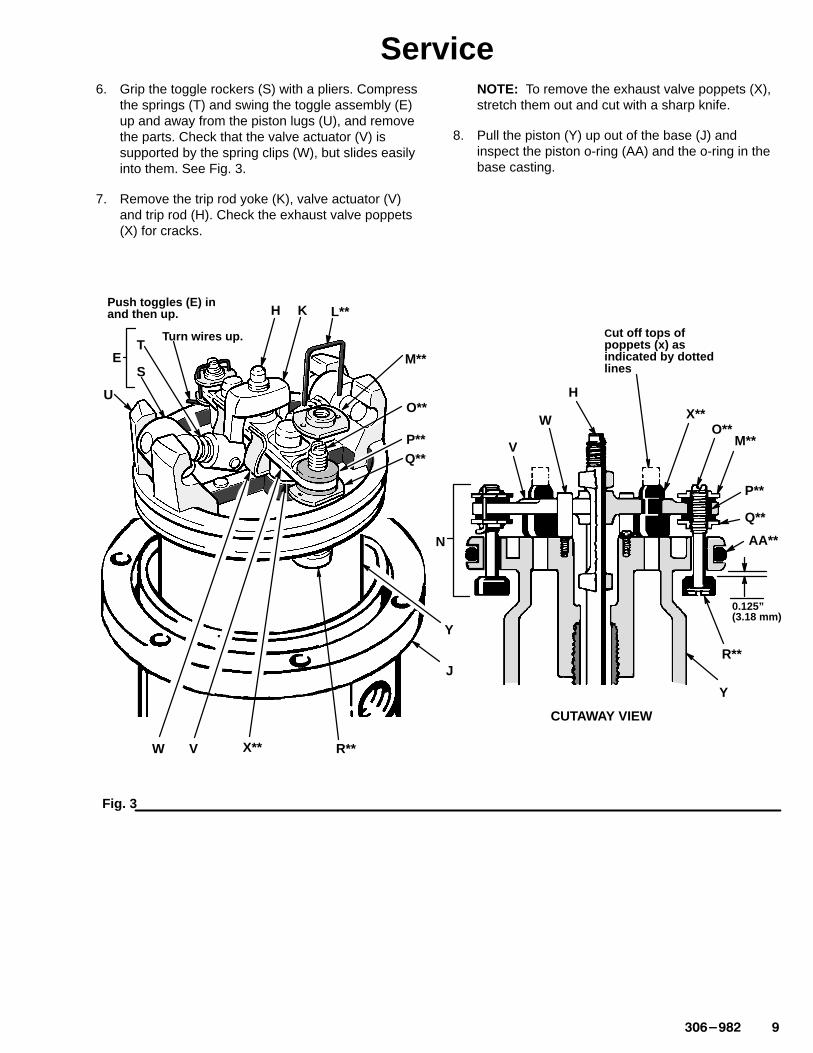
Service6. Grip the toggle rockers (S) with a pliers. Compress
the springs (T) and swing the toggle assembly (E)up and away from the piston lugs (U), and removethe parts. Check that the valve actuator (V) issupported by the spring clips (W), but slides easilyinto them. See Fig. 3.
7. Remove the trip rod yoke (K), valve actuator (V)and trip rod (H). Check the exhaust valve poppets(X) for cracks.
NOTE: To remove the exhaust valve poppets (X),stretch them out and cut with a sharp knife.
8. Pull the piston (Y) up out of the base (J) andinspect the piston o-ring (AA) and the o-ring in thebase casting.
Cut off tops ofpoppets (x) as indicated by dottedlines
0.125” (3.18 mm)
CUTAWAY VIEW
Fig. 3
E
Push toggles (E) in and then up.
Turn wires up.
U
H K L**
M**
O**
P**
Y
J
T
S
W X**V
Q**
R**
H
W
V
X**O**
M**
P**
Q**
AA**
Y
R**
N

�� �������
ServiceReassembly
1. Clean all the parts carefully in a compatible solventand inspect for wear or damage. Use all the repairkit parts during reassembly and replace other partsas necessary.
2. Check the polished surfaces of the piston, pistonrod and cylinder wall for scratches or wear. Ascored rod will cause premature packing wear andleaking.
3. Lubricate all parts with a light, waterproof grease.
4. Be sure the o-rings are in place. Slide the pistonrod down through the throat bearing and lower thepiston (Y) into the air motor base (J).
5. Pull the exhaust valve poppets (X**) into the valveactuator (V) and clip off the top part shown withdotted lines. See Fig. 3.
6. Install the transfer valve poppets (R**) onto thevalve stems (O**), then reassemble the valvestems (O**), bottom adjusting nuts (Q**),grommets (P**), and top adjusting nuts (M**) onthe piston (Y). Assemble the trip rod (H), valveactuator (V), trip rod yoke (K) and toggleassemblies (E) on the piston. See Fig. 3.
7. Before installing the lockwires (L**) in the adjustingnuts (M** and Q**), use the special gauge171–818 to adjust the transfer valve (N) so there is0.145 in. (3.68 mm) clearance between thepoppets (R**) and the piston (Y) when the toggleassemblies are in the down position. See Fig. 3.
8. Snap the toggle assemblies (E) to the up position.Reinstall the cylinder (G) and cap nut (F).Reassemble the air motor to the displacementpump.
9. Before remounting the pump, connect an air hoseand run the pump slowly, at about 40 psi(0.28 MPa, 2.8 bar) to ensure that it operatessmoothly.
10. Reconnect the ground wire before regularoperation of the pump.

���������
ServiceThroat Packing Service for In-Line Pump Model 205–647
The piston in the air motor, located behind the airmotor plates, moves when air is supplied to themotor. Moving parts can pinch or amputate yourfingers or other body parts. Therefore, neveroperate the pump with the air motor platesremoved.
WARNING
NOTE: See Fig. 4 on page 12 and the Parts Drawingon page 14.
1. Clamp the pump in a vise and unscrew thedisplacement cylinder (CC) from the air motorbase (J). Pull the displacement cylinder away fromthe air motor until the cotter pin (DD) whichsecures the displacement pump connecting rod tothe air motor piston rod (FF) is visible. See Fig. 4.
2. Remove the cotter pin (DD) and unscrew the pumpconnecting rod (EE) from the air motor piston rod(FF). See Fig. 4. Remove the cylinder (G) from theair motor base (J) as described underDisassembly on page 8.
3. Remove one louvered air exhaust plate (BB) andunscrew the throat packing nut (HH), using aspanner wrench or a 0.22 in. (5.6 mm) diameterrod. See Fig. 4. Remove the spacer and packingfrom the base and packing nut. Clean the throatpacking area in the base and the packing nut.Clean and inspect all parts and replace asnecessary.
4. Lubricate the packings, piston rod and pistonflange with a light waterproof grease. Reinstall thespacer and packing in the base and packing nut.Be sure the lips of the v-packings face down. SeeDetail B. Screw the packing nut loosely into thebase. Carefully slide the piston rod down throughthe throat packing and lower the piston into thebase. Tighten the packing nut securely. Reinstallthe plate (BB) and cylinder (G). Reassemble theair motor to the displacement pump.
CAUTIONWhen reinstalling cotter pin (DD), always spread andflatten the pin (both the head and prongs) around therod to within a 1 in. (25 mm) total diameter. SeeDetail A of Fig. 4.
�� �������
Service
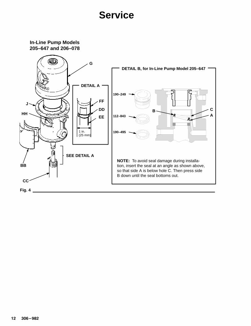
Fig. 4
HH
BB
CC
J
G
SEE DETAIL A
FF
DD
EE
1 in.(25 mm)
DETAIL A
NOTE: To avoid seal damage during installa-tion, insert the seal at an angle as shown above,so that side A is below hole C. Then press sideB down until the seal bottoms out.
CA
190–249
B112–843
190–495
DETAIL B, for In-Line Pump Model 205–647
In-Line Pump Models205–647 and 206–078

���������
ServiceThroat Packing Service for In-Line Pump Model 206–078
The piston in the air motor, located behind the airmotor plates, moves when air is supplied to themotor. Moving parts can pinch or amputate yourfingers or other body parts. Therefore, neveroperate the pump with the air motor platesremoved.
WARNING
See Fig. 4 on page 12 and the Parts Drawing onpage 16.
1. Clamp the pump in a vise and unscrew thedisplacement cylinder (CC) from the air motorbase (J). Pull the displacement cylinder away fromthe air motor until the cotter pin (DD) whichsecures the displacement pump connecting rod tothe air motor piston rod (FF) is visible. See Fig. 4.
2. Remove the cotter pin (DD) and unscrew the pumpconnecting rod (EE) from the air motor piston rod(FF). See Fig. 4. Remove the cylinder (G) from theair motor base (J) as described underDisassembly on page 8.
3. Remove one louvered air exhaust plate (BB) andunscrew the throat packing nut (HH), using aspanner wrench or a 0.22 in. (5.6 mm) diameterrod. See Fig. 4.
4. Remove the packing nut (45�), male and femaleglands (47�, 48�), v-packings (49�), washer(44�), bearing (46�), retainer (24�), wiper (22�),o-ring (23�), u-cup (25�), and washer (26�) fromthe base.
5. Clean the throat packing area in the base and thepacking nut. Clean and inspect all parts, andreplace as necessary.
6. Lubricate the packings, piston rod and pistonflange with a light waterproof grease.
7. Install the washer (26�) into the base. Assemblethe packing (25�) and the wiper (22�) into theretainer (24�). Install the o-ring (23�) onto theretainer, and insert the retainer assembly into thebase.
NOTE: Make sure the packing (25�) lips facedown, and make sure the wiper (22�) lips face up.
8. Insert the bearing (46�) and the washer (44�) intothe base. Assemble the female gland (48�),v-packings (49�), and the male gland (47�) intothe packing nut (45�).
9. Reinstall the spacer and packing in the base andpacking nut (45�). Screw the packing nut into thebase, and tighten it securely. Carefully slide thepiston rod (FF) down through the throat packing,and lower the piston into the base. Reinstall theplate (BB) and cylinder (G). Reassemble the airmotor to the displacement pump.
10. Torque the outlet adapter (42) to 45 to 55 ft-lb (61to 75 N-m).
CAUTIONWhen reinstalling cotter pin (DD), always spread andflatten the pin (both the head and prongs) around therod to within a 1 in. (25 mm) total diameter. SeeDetail A of Fig. 4.
�� ������
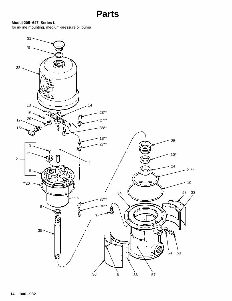
PartsModel 205–647, Series Lfor in-line mounting, medium-pressure oil pump
12
3
*4
5
6
7
8
*9
10*
13 14
15
16
17
18**
19**20
21**24
25
27**
27**
28**
29
30**
31
32
33
34
35
36
33
37**
38**
5354
57
58

��������
PartsModel 205–647, Series Lfor in-line mounting, medium-pressure oil pump
Ref No. Part No. Description Qty
1 207–150 TRIP ROD 12 207–391 PISTON
includes items 3 to 5 (also includes207–385 repair kit when orderedas a replacement part) 1
3 102–975 .SCREW, rd hd mach; 6–32 x 1/4” 24 158–361* .CLIP, spring 25 .BARE PISTON (not sold separately) 16 100–078 SCREW, hex head; 8–32 x 3/8” . 207 101–578 SCREW, hex head Nylock;
8–32 x 3/8” . 88 150–647 GASKET; copper 19 156–698* O-RING; Buna–N 110 112–843* PACKING, block, V 113 158–359 ACTUATOR, valve 114 158–360 YOKE, rod, trip 115 158–362 PIN, toggle 216 158–364 ROCKER, toggle 217 167–585 SPRING, helical compression 218 158–367** GROMMET; rubber 219 158–377 SEAL, flat ring; nitrile rubber 120 158–378** SEAL, o-ring; nitrile rubber 121 158–379** SEAL, o-ring; nitrile rubber 124 190–495 SPACER, throat 125 190–249 NUT, packing 127 160–261** NUT, adjusting 428 160–618** LOCKWIRE, transfer valve 229 160–623 ARM, toggle 2
Ref No. Part No. Description Qty
30 160–896** STEM, valve 231 161–435 NUT, cylinder cap 132 162–629 CYLINDER, motor, air 133 178–270 PLATE, muffler 234 164–924 BASE, motor, air 135 164–925 ROD, piston 136 177–844 PLATE, identification 137 170–708** POPPET, valve; urethane 238 170–709** POPPET, valve; urethane 253 104–029 LUG, grounding 154 104–582 WASHER, tab 157 180–233 LABEL, warning 258� 177–843 PLATE, warning 1
* Recommended spare parts to keep on hand.
** Included in Repair Kit 207–385. Must be purchased separately.
� If users of this equipment do not read English, youmay order one of the following labels to apply toyour air motor. Apply the label over the matchinglabel on the air motor plate for good visibility. Donot cover the air exhaust holes. Order the labelsfree of charge directly from Graco. Toll free:1–800–367–4023.
German 290–467French 290–466Spanish 290–468
�� �������
Parts
12
3
*4
5
7
8
*9
1314
15
16
17
18**
**20
27**
27**
28**
29
30**
31
32
36
37**
38**
58
Model 206–078, Series Lfor in-line mounting, high-pressure grease pump
4155
5150
4240
52
56
48�
������
46�
22�
45�
23�
24�
25�
26�
44�
47�
49�
21**
19
33
54 53
3357
6
� Torque to 45 to 55 ft-lb (61 to 75 N-m).
�
��������
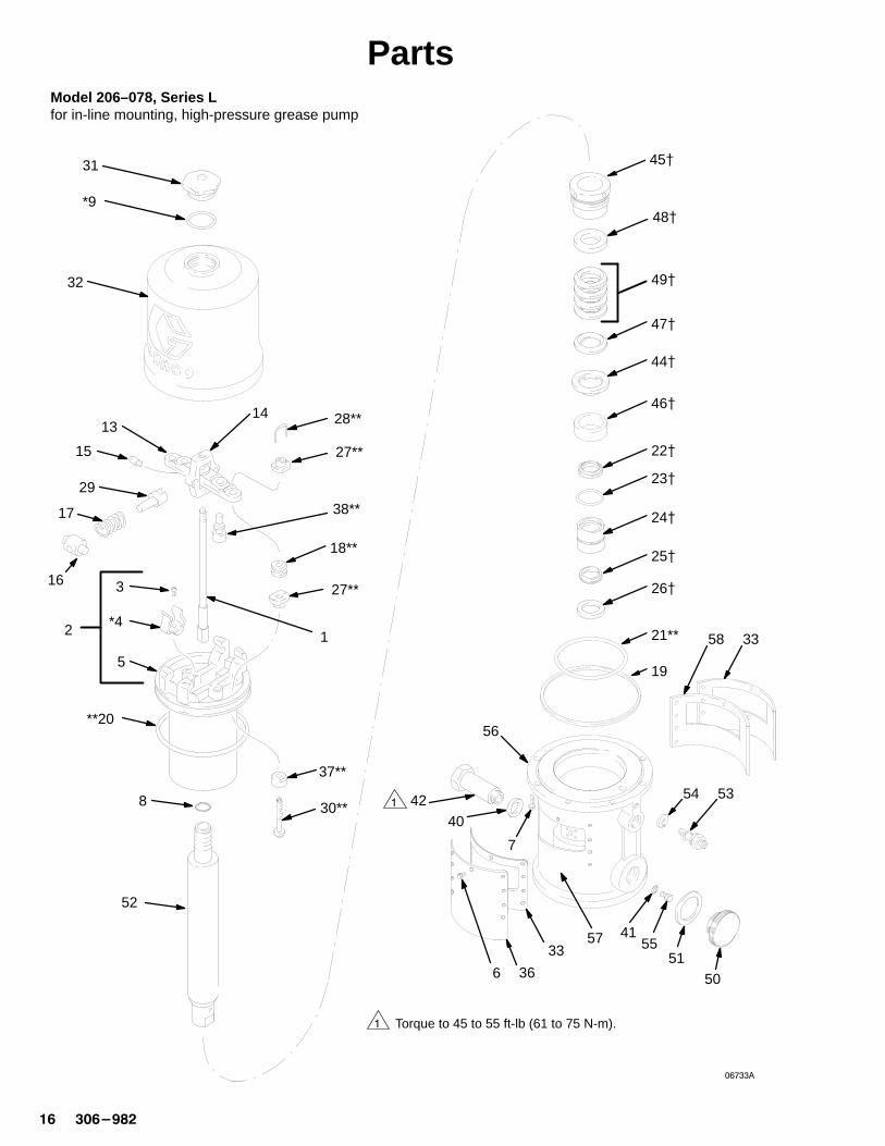
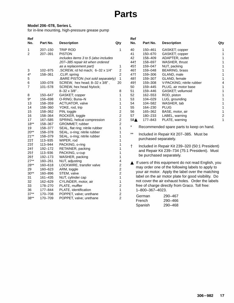
PartsModel 206–078, Series Lfor in-line mounting, high-pressure grease pump
Ref No. Part No. Description Qty
1 207–150 TRIP ROD 12 207–391 PISTON
includes items 3 to 5 (also includes207–385 repair kit when orderedas a replacement part) 1
3 102–975 .SCREW, rd hd mach; 6–32 x 1/4” 24* 158–361 .CLIP, spring 25 .BARE PISTON (not sold separately) 16 100–078 SCREW, hex head; 8–32 x 3/8” . 207 101–578 SCREW, hex head Nylock;
8–32 x 3/8” . 88 150–647 GASKET; copper 19* 156–698 O-RING; Buna–N 113 158–359 ACTUATOR, valve 114 158–360 YOKE, rod, trip 115 158–362 PIN, toggle 216 158–364 ROCKER, toggle 217 167–585 SPRING, helical compression 218** 158–367 GROMMET; rubber 219 158–377 SEAL, flat ring; nitrile rubber 120** 158–378 SEAL, o-ring; nitrile rubber 121** 158–379 SEAL, o-ring; nitrile rubber 122� 113–935 WIPER, rod 123� 113–944 PACKING, o-ring 124� 192–172 RETAINER, packing 125� 113–936 PACKING, u-cup 126� 192–173 WASHER, packing 127** 160–261 NUT, adjusting 428** 160–618 LOCKWIRE, transfer valve 229 160–623 ARM, toggle 230** 160–896 STEM, valve 231 161–435 NUT, cylinder cap 132 162–629 CYLINDER, motor, air 133 178–270 PLATE, muffler 236 177–844 PLATE, identification 137** 170–708 POPPET, valve; urethane 238** 170–709 POPPET, valve; urethane 2
Ref No. Part No. Description Qty
40 150–461 GASKET; copper 141 150–670 GASKET; copper 142 158–409 ADAPTER, outlet 144� 158–697 WASHER, thrust 145� 159–047 NUT, packing 146� 159–048 BEARING, brass 147� 159–306 GLAND, male 148� 159–307 GLAND, female 149� 159–308 V-PACKING; nitrile rubber 450 159–445 PLUG, air motor base 151 159–446 GASKET; vellumoid 152 162–553 ROD, piston 153 104–029 LUG, grounding 154 104–582 WASHER, tab 155 164–230 PLUG 156 165–362 BASE, motor, air 157 180–233 LABEL, warning 258� 177–843 PLATE, warning 1
* Recommended spare parts to keep on hand.
** Included in Repair Kit 207–385. Must be purchased separately.
� Included in Repair Kit 239–320 (50:1 President)and Repair Kit 239–734 (75:1 President). Mustbe purchased separately.
� If users of this equipment do not read English, youmay order one of the following labels to apply toyour air motor. Apply the label over the matchinglabel on the air motor plate for good visibility. Donot cover the air exhaust holes. Order the labelsfree of charge directly from Graco. Toll free:1–800–367–4023.
German 290–467French 290–466Spanish 290–468
�� �������
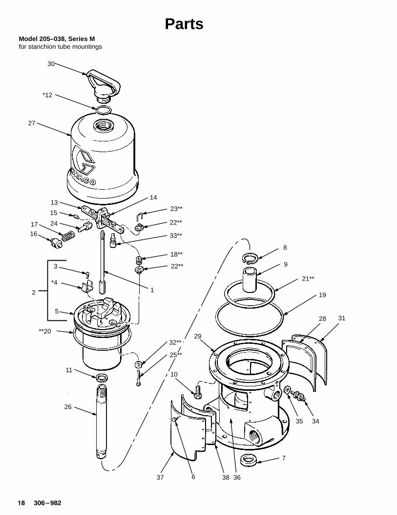
Parts
12
3
*4
5
6
1314
15
1617
18**
19
**20
21**
22**
22**
23**
24
33**
Model 205–038, Series Mfor stanchion tube mountings
30
*12
27
11
32**
25**
10
26
8
9
28 31
35 34
7
363837
29
���������
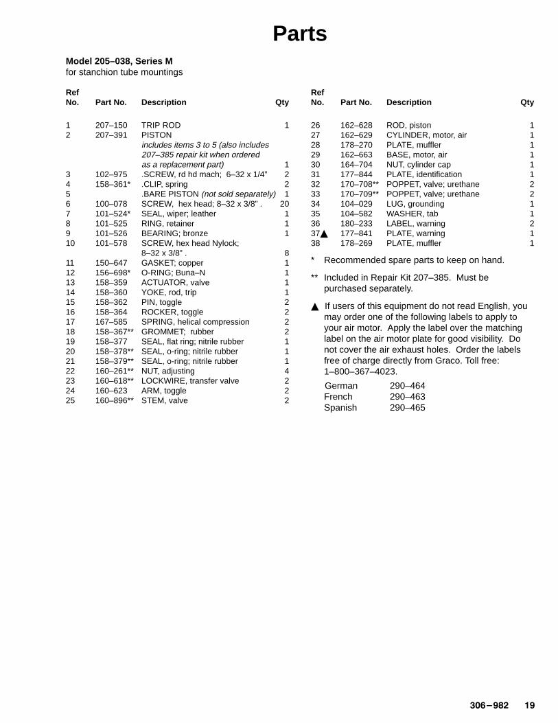
PartsModel 205–038, Series Mfor stanchion tube mountings
Ref No. Part No. Description Qty
1 207–150 TRIP ROD 12 207–391 PISTON
includes items 3 to 5 (also includes207–385 repair kit when orderedas a replacement part) 1
3 102–975 .SCREW, rd hd mach; 6–32 x 1/4” 24 158–361* .CLIP, spring 25 .BARE PISTON (not sold separately) 16 100–078 SCREW, hex head; 8–32 x 3/8” . 207 101–524* SEAL, wiper; leather 18 101–525 RING, retainer 19 101–526 BEARING; bronze 110 101–578 SCREW, hex head Nylock;
8–32 x 3/8” . 811 150–647 GASKET; copper 112 156–698* O-RING; Buna–N 113 158–359 ACTUATOR, valve 114 158–360 YOKE, rod, trip 115 158–362 PIN, toggle 216 158–364 ROCKER, toggle 217 167–585 SPRING, helical compression 218 158–367** GROMMET; rubber 219 158–377 SEAL, flat ring; nitrile rubber 120 158–378** SEAL, o-ring; nitrile rubber 121 158–379** SEAL, o-ring; nitrile rubber 122 160–261** NUT, adjusting 423 160–618** LOCKWIRE, transfer valve 224 160–623 ARM, toggle 225 160–896** STEM, valve 2
Ref No. Part No. Description Qty
26 162–628 ROD, piston 127 162–629 CYLINDER, motor, air 128 178–270 PLATE, muffler 129 162–663 BASE, motor, air 130 164–704 NUT, cylinder cap 131 177–844 PLATE, identification 132 170–708** POPPET, valve; urethane 233 170–709** POPPET, valve; urethane 234 104–029 LUG, grounding 135 104–582 WASHER, tab 136 180–233 LABEL, warning 237� 177–841 PLATE, warning 138 178–269 PLATE, muffler 1
* Recommended spare parts to keep on hand.
** Included in Repair Kit 207–385. Must be purchased separately.
� If users of this equipment do not read English, youmay order one of the following labels to apply toyour air motor. Apply the label over the matchinglabel on the air motor plate for good visibility. Donot cover the air exhaust holes. Order the labelsfree of charge directly from Graco. Toll free:1–800–367–4023.
German 290–464French 290–463Spanish 290–465

�� �������
Parts
18**
19
**20
21**
22**
22**
23**24
27
25**
28
Model 207–352, Series Ffor divorced mountings
26
*13
3017
16
14 15
34**
7
*8
9
6
33**
12
29
11
32
1includesitems 2 to 4
38
1031 28 37
36 35
5

���������
PartsModel 207–352, Series Ffor divorced mountings
Ref No. Part No. Description Qty
1 205–529 PACKING NUTincludes items 2 to 4 1
2 101–524* .SEAL, wiper; leather 13 101–526 .BEARING; bronze 14 164–701 .NUT, packing 15 207–150 TRIP ROD 16 207–391 PISTON
includes items 7 to 9 (also includes207–385 repair kit when orderedas a replacement part) 1
7 102–975 .SCREW, rd hd mach; 6–32 x 1/4” 28 158–361* .CLIP, spring 29 .BARE PISTON (not sold separately) 110 100–078 SCREW, hex head; 8–32 x 3/8” . 2011 101–578 SCREW, hex head Nylock;
8–32 x 3/8” . 812 150–647 GASKET; copper 113 156–698* O-RING; Buna–N 114 158–359 ACTUATOR, valve 115 158–360 YOKE, rod, trip 116 158–362 PIN, toggle 217 158–364 ROCKER, toggle 218 158–367** GROMMET; rubber 219 158–377 SEAL, flat ring; nitrile rubber 120 158–378** SEAL, o-ring; nitrile rubber 121 158–379** SEAL, o-ring; nitrile rubber 122 160–261** NUT, adjusting 423 160–618** LOCKWIRE, transfer valve 224 160–623 ARM, toggle 225 160–896** STEM, valve 2
Ref No. Part No. Description Qty
26 161–435 NUT, cylinder cap 127 162–629 CYLINDER, motor, air 128 178–270 PLATE, muffler 229 166–235 ROD, piston 130 167–585 SPRING, helical compression 231 177–844 PLATE, identification 132 168–656 BASE, motor, air 133 170–708** POPPET, valve; urethane 234 170–709** POPPET, valve; urethane 235 104–029 LUG, grounding 136 104–582 WASHER, tab 137 180–233 LABEL, warning 238� 177–843 PLATE, warning 1
* Recommended spare parts to keep on hand.
** Included in Repair Kit 207–385. Must be purchased separately.
� If users of this equipment do not read English, youmay order one of the following labels to apply toyour air motor. Apply the label over the matchinglabel on the air motor plate for good visibility. Donot cover the air exhaust holes. Order the labelsfree of charge directly from Graco. Toll free:1–800–367–4023.
German 290–467French 290–466Spanish 290–468
�� �������
Parts
18**
19
**20
21**
22**
22**
23**24
27
25**
28
26
*13
3017
16
14 15
34**
7
*8
9
6
33**
12
29
11
32
38
1031 28 37
36 35
Model 222–772, Series Ffor divorced mountings
1includesitems 2 to 4
5

���������
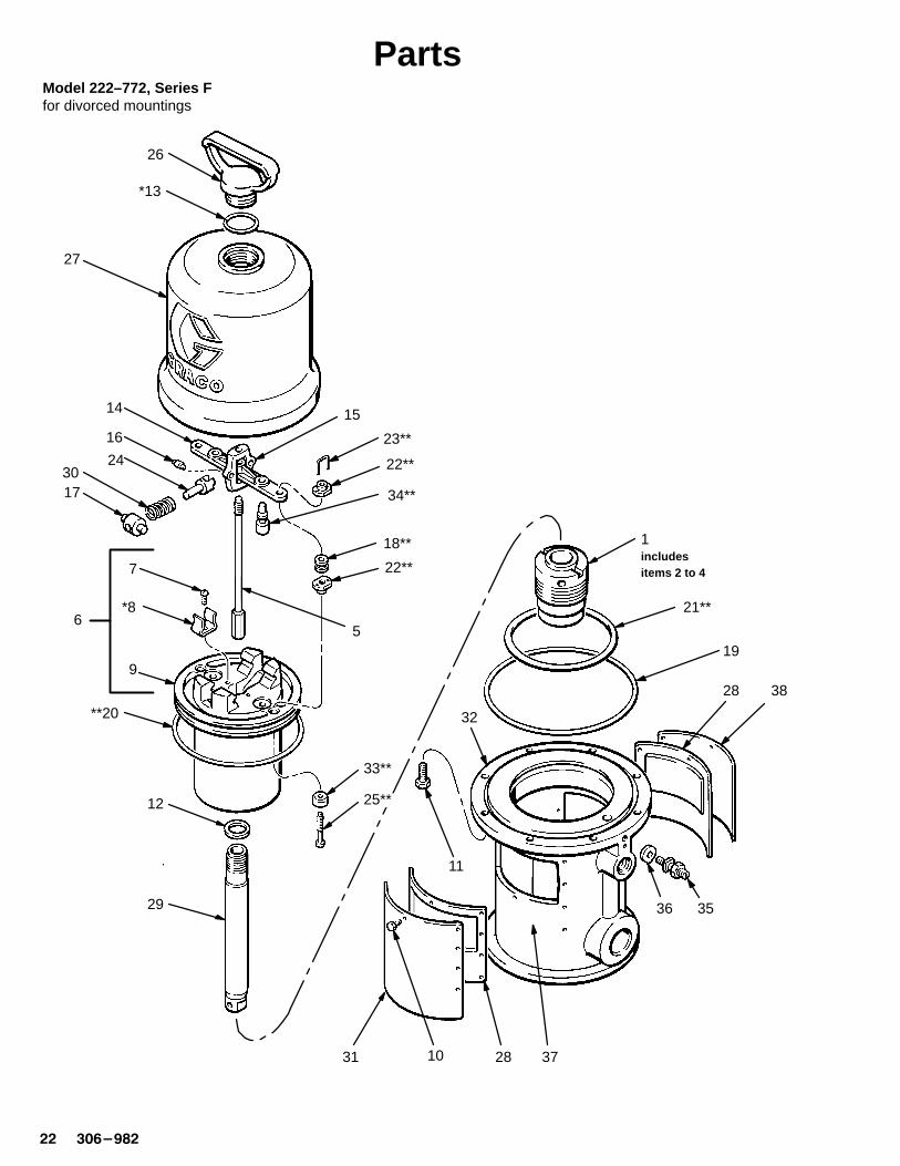
PartsModel 222–772, Series Ffor divorced mountings
Ref No. Part No. Description Qty
1 205–529 PACKING NUTincludes items 2 to 4 1
2 101–524* .SEAL, wiper; leather 13 101–526 .BEARING; bronze 14 164–701 .NUT, packing 15 207–150 TRIP ROD 16 207–391 PISTON
includes items 7 to 9 (also includes207–385 repair kit when orderedas a replacement part) 1
7 102–975 .SCREW, rd hd mach; 6–32 x 1/4” 28 158–361* .CLIP, spring 29 .BARE PISTON (not sold separately) 110 100–078 SCREW, hex head; 8–32 x 3/8” . 2011 101–578 SCREW, hex head Nylock;
8–32 x 3/8” . 812 150–647 GASKET; copper 113 156–698* O-RING; Buna–N 114 158–359 ACTUATOR, valve 115 158–360 YOKE, rod, trip 116 158–362 PIN, toggle 217 158–364 ROCKER, toggle 218 158–367** GROMMET; rubber 219 158–377 SEAL, flat ring; nitrile rubber 120 158–378** SEAL, o-ring; nitrile rubber 121 158–379** SEAL, o-ring; nitrile rubber 122 160–261** NUT, adjusting 423 160–618** LOCKWIRE, transfer valve 224 160–623 ARM, toggle 225 160–896** STEM, valve 2
Ref No. Part No. Description Qty
26 164–704 NUT, cylinder cap 127 162–629 CYLINDER, motor, air 128 178–270 PLATE, muffler 229 166–235 ROD, piston 130 167–585 SPRING, helical compression 231 177–844 PLATE, identification 132 184–120 BASE, motor, air 133 170–708** POPPET, valve; urethane 234 170–709** POPPET, valve; urethane 235 104–029 LUG, grounding 136 104–582 WASHER, tab 137 180–233 LABEL, warning 238� 177–843 PLATE, warning 1
* Recommended spare parts to keep on hand.
** Included in Repair Kit 207–385. Must be purchased separately.
� If users of this equipment do not read English, youmay order one of the following labels to apply toyour air motor. Apply the label over the matchinglabel on the air motor plate for good visibility. Donot cover the air exhaust holes. Order the labelsfree of charge directly from Graco. Toll free:1–800–367–4023.
German 290–467French 290–466Spanish 290–468

�� �������
AccessoriesMust be purchased separately.
Grounding Clamp 103–538Ground W ire 208–950
12 ga (1.5 mm�),25 ft (7.6 m) long
Bleed-Type Master Air V alve (Required)300 psi (2.1 MPa, 21 bar) MAXIMUM WORKINGPRESSURE
Relieves air trapped in the air line between the pumpair inlet and this valve when closed.107–141 3/4 npt(m) inlet x 3/4 npt(f) outlet107–142 1/2 npt(m) inlet x 1/2 npt(f) outlet
Air Line Filter
106–148 3/8” npt inlet and outlet106–149 1/2” npt inlet and outlet
250 psi (1.74 MPa, 17.4 bar) MAXIMUM WORKINGPRESSURE
Padded Pliers 207–579
Use to grip trip rod during air motor servicing, to preventdamage to rod.
Valve Stem Gauge 171–818
Use to check transfer valve clearance during air motorservicing.
Muffler Kit 214–873
Replaces existing motor muffler to reduce noise and oilmist emissions. Includes separate manual 307–361.

���������
4.38” (111.3 mm) dia.
5” (127 mm)2.5” (64 mm)
0.28” (7.2 mm) dia.
161–322 GASKET
45�
45�
45�
4” (102 mm)
2.5”(64 mm)
2.5”(64 mm)
1” (25 mm)radius
three0.34” (8.6 mm)dia. holes on6.38” (162.1 mm)bolt circle
1/4–20 holes
gasket 161–096
two0.31” (7.9mm)dia. holeson 5” (127mm)bolt circle 45�
0.88” (22.4 mm) dia.
3.25” (82.6 mm) DIA.
2.09”(53.1 mm)
3-Tie-Rod Pumps
2-Stanchion-T ube Pumps
In-Line Pumps
Mounting HoleLayouts
14.75” (375 mm)Models205–647206–078207–352
16.45” (418 mm)Models205–038222–772
7.25”(184.2 mm)diameter
1/2nptairinlet
DimensionalDrawing

�� �������
Technical DataMaximum inbound air pressure 180 psi (1.2 MPa, 12 bar). . . . . . . . . . . . . . . . . . . . . . . . . . . . . . . . . . . . . . . . . . . . . . . . . . . Effective piston area 14 sq. in. (90 cm�). . . . . . . . . . . . . . . . . . . . . . . . . . . . . . . . . . . . . . . . . . . . . . . . . . . . . . . . . . . . . . . . . . . Effective piston diameter 4.25 in. (108 mm). . . . . . . . . . . . . . . . . . . . . . . . . . . . . . . . . . . . . . . . . . . . . . . . . . . . . . . . . . . . . . . . Stroke 4 in. (102 mm). . . . . . . . . . . . . . . . . . . . . . . . . . . . . . . . . . . . . . . . . . . . . . . . . . . . . . . . . . . . . . . . . . . . . . . . . . . . . . . . . . Air valves Transfer: nitrile rubber. . . . . . . . . . . . . . . . . . . . . . . . . . . . . . . . . . . . . . . . . . . . . . . . . . . . . . . . . . . . . . . . . . . . . . . . .
Exhaust: urethaneValve mechanism balanced, detented. . . . . . . . . . . . . . . . . . . . . . . . . . . . . . . . . . . . . . . . . . . . . . . . . . . . . . . . . . . . . . . . . . . . Seal Nitrile rubber. . . . . . . . . . . . . . . . . . . . . . . . . . . . . . . . . . . . . . . . . . . . . . . . . . . . . . . . . . . . . . . . . . . . . . . . . . . . . . . . . . . . . . Weight approx. 19 lb (8.6 kg). . . . . . . . . . . . . . . . . . . . . . . . . . . . . . . . . . . . . . . . . . . . . . . . . . . . . . . . . . . . . . . . . . . . . . . . . . . . * Sound level at 180 psi (1.2 MPa, 12 bar), 25 cycles per minute 98 dBa. . . . . . . . . . . . . . . . . . . . . . . . . . . . . . . . . . . . . . * Sound power level at 180 psi (1.2 MPa, 12 bar), 25 cycles per minute 113 dBa. . . . . . . . . . . . . . . . . . . . . . . . . . . . . . .
* Tested in accordance with ISO 3744.
Manual Change SummaryThis manual went from Rev. Y to Rev. Z to list the separate repair kits, 239–320 and 239–734, that are available forModel 206–078. See Parts, page 17.

���������
Notes

�� �������
Graco Standard W arranty Graco warrants all equipment manufactured by Graco and bearing its name to be free from defects in material and workmanship on thedate of sale by an authorized Graco distributor to the original purchaser for use. With the exception of any special, extended, or limitedwarranty published by Graco, Graco will, for a period of twelve months from the date of sale, repair or replace any part of the equipmentdetermined by Graco to be defective. This warranty applies only when the equipment is installed, operated and maintained inaccordance with Graco’s written recommendations.
This warranty does not cover, and Graco shall not be liable for general wear and tear, or any malfunction, damage or wear caused byfaulty installation, misapplication, abrasion, corrosion, inadequate or improper maintenance, negligence, accident, tampering, orsubstitution of non-Graco component parts. Nor shall Graco be liable for malfunction, damage or wear caused by the incompatibility ofGraco equipment with structures, accessories, equipment or materials not supplied by Graco, or the improper design, manufacture,installation, operation or maintenance of structures, accessories, equipment or materials not supplied by Graco.
This warranty is conditioned upon the prepaid return of the equipment claimed to be defective to an authorized Graco distributor forverification of the claimed defect. If the claimed defect is verified, Graco will repair or replace free of charge any defective parts. Theequipment will be returned to the original purchaser transportation prepaid. If inspection of the equipment does not disclose any defectin material or workmanship, repairs will be made at a reasonable charge, which charges may include the costs of parts, labor, andtransportation.
THIS WARRANTY IS EXCLUSIVE, AND IS IN LIEU OF ANY OTHER W ARRANTIES, EXPRESS OR IMPLIED, INCLUDING BUTNOT LIMITED TO WARRANTY OF MERCHANTABILITY OR WARRANTY OF FITNESS FOR A PARTICULAR PURPOSE.
Graco’s sole obligation and buyer’s sole remedy for any breach of warranty shall be as set forth above. The buyer agrees that no otherremedy (including, but not limited to, incidental or consequential damages for lost profits, lost sales, injury to person or property, or anyother incidental or consequential loss) shall be available. Any action for breach of warranty must be brought within two (2) years of thedate of sale.
Graco makes no warranty, and disclaims all implied warranties of merchantability and fitness for a particular purpose in connectionwith accessories, equipment, materials or components sold but not manufactured by Graco. These items sold, but not manufacturedby Graco (such as electric motors, switches, hose, etc.), are subject to the warranty, if any, of their manufacturer. Graco will providepurchaser with reasonable assistance in making any claim for breach of these warranties.
In no event will Graco be liable for indirect, incidental, special or consequential damages resulting from Graco supplying equipmenthereunder, or the furnishing, performance, or use of any products or other goods sold hereto, whether due to a breach of contract,breach of warranty, the negligence of Graco, or otherwise.
FOR GRACO CANADA CUSTOMERSThe parties acknowledge that they have required that the present document, as well as all documents, notices and legal proceedingsentered into, given or instituted pursuant hereto or relating directly or indirectly hereto, be drawn up in English. Les partiesreconnaissent avoir convenu que la rédaction du présente document sera en Anglais, ainsi que tous documents, avis et procéduresjudiciaires exécutés, donnés ou intentés à la suite de ou en rapport, directement ou indirectement, avec les procedures concernées.
Graco Phone NumberTO PLACE AN ORDER , contact your Graco distributor, or call this number to identify the distributor closest to you:
1–800–367–4023 Toll Free
All written and visual data contained in this document reflects the latest product information available at the time of publication.Graco reserves the right to make changes at any time without notice.
Sales Offices: Minneapolis, Detroit, Los AngelesForeign Offices: Belgium, Canada, England, Korea, France, Germany, Hong Kong, Japan
GRACO INC. P.O. BOX 1441 MINNEAPOLIS, MN 55440–1441http://www.graco.com
PRINTED IN U.S.A. 306–982 November 1968, Revised February 1998