President 4-Ball Pumps - Graco® 4-Ball Pumps 3A3383C EN Air ... a template. Use either of the two...
22
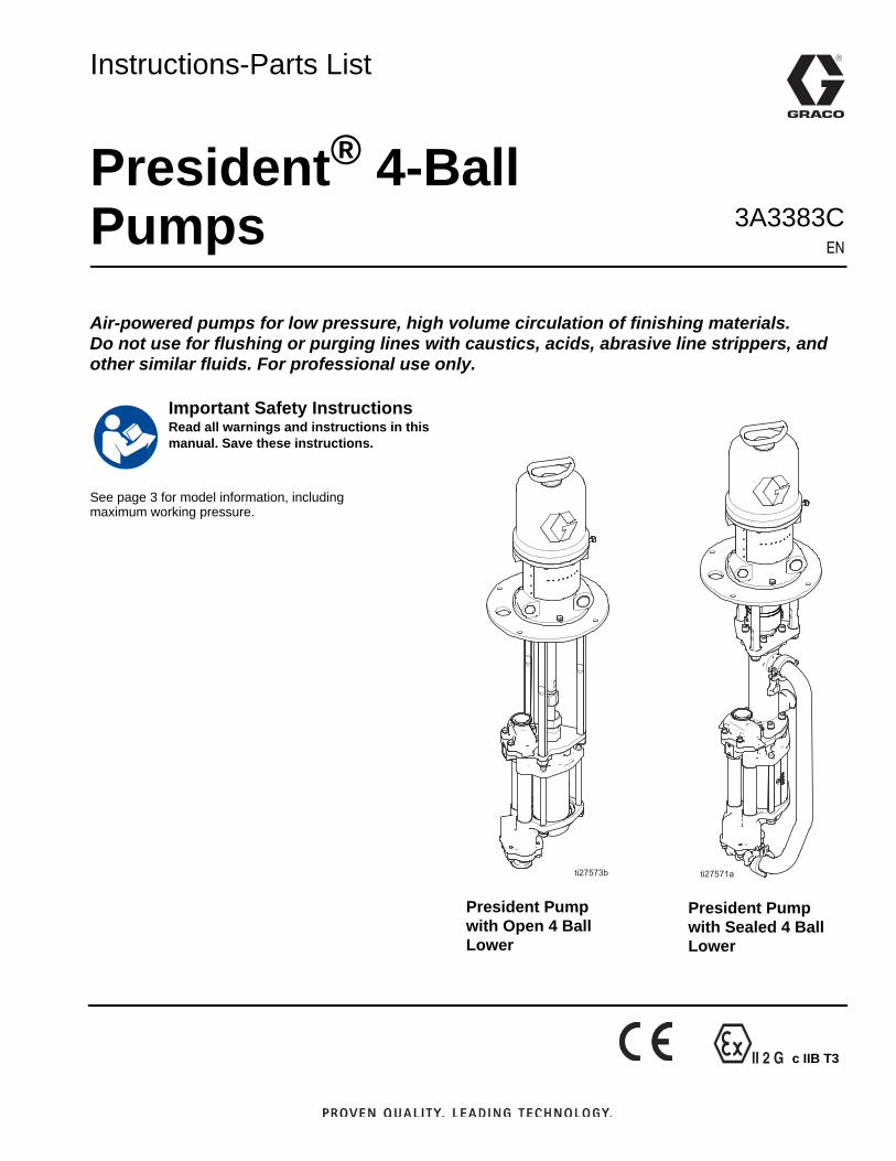
II 2 G c IIB T3 Instructions-Parts List President ® 4-Ball Pumps 3A3383C EN Air-powered pumps for low pressure, high volume circulation of finishing materials. Do not use for flushing or purging lines with caustics, acids, abrasive line strippers, and other similar fluids. For professional use only. See page 3 for model information, including maximum working pressure. Important Safety Instructions Read all warnings and instructions in this manual. Save these instructions. President Pump with Open 4 Ball Lower President Pump with Sealed 4 Ball Lower
Transcript of President 4-Ball Pumps - Graco® 4-Ball Pumps 3A3383C EN Air ... a template. Use either of the two...
II 2 G c IIB T3
Instructions-Parts List
President® 4-Ball Pumps 3A3383C
EN
Air-powered pumps for low pressure, high volume circulation of finishing materials.Do not use for flushing or purging lines with caustics, acids, abrasive line strippers, and other similar fluids. For professional use only.
See page 3 for model information, includingmaximum working pressure.
Important Safety InstructionsRead all warnings and instructions in this manual. Save these instructions.
President Pump with Open 4 Ball Lower
President Pump with Sealed 4 Ball Lower
2 3A3383C
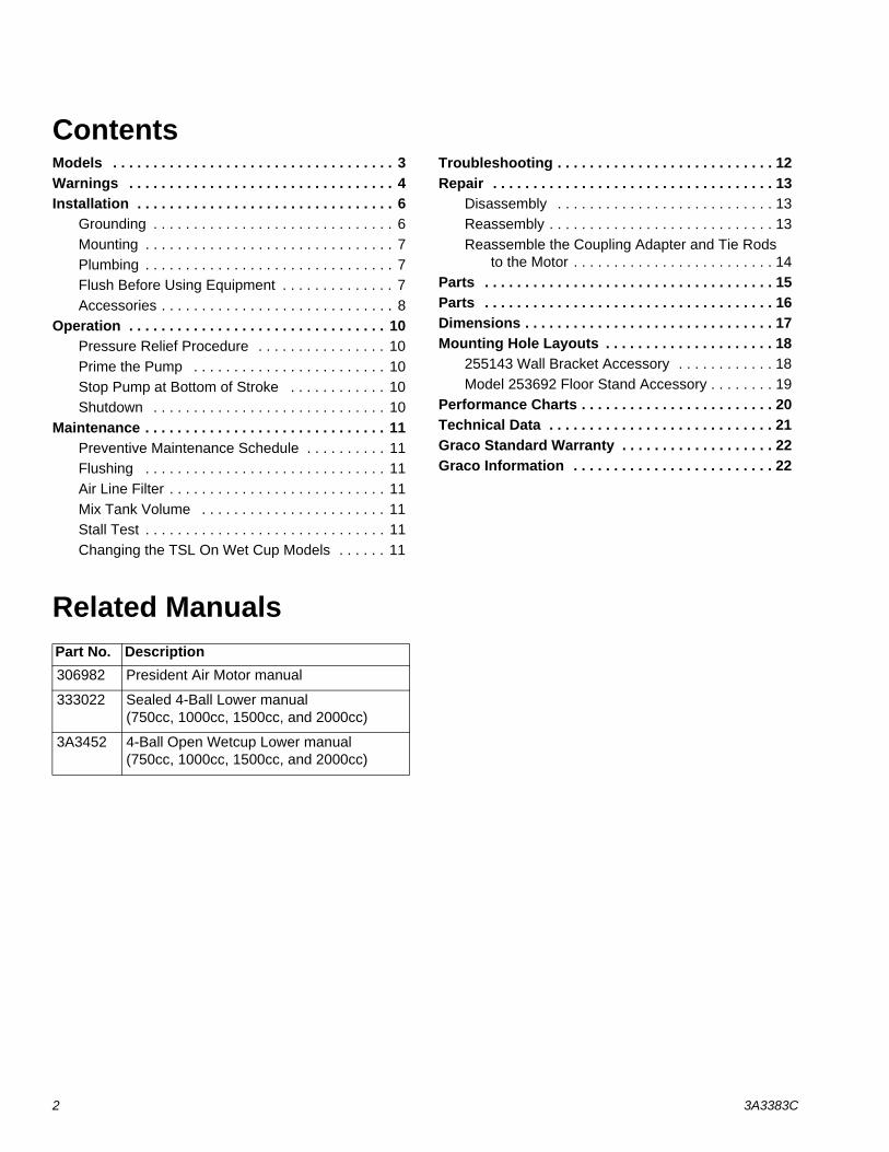
Contents Models . . . . . . . . . . . . . . . . . . . . . . . . . . . . . . . . . . . 3Warnings . . . . . . . . . . . . . . . . . . . . . . . . . . . . . . . . . 4Installation . . . . . . . . . . . . . . . . . . . . . . . . . . . . . . . . 6
Grounding . . . . . . . . . . . . . . . . . . . . . . . . . . . . . . 6Mounting . . . . . . . . . . . . . . . . . . . . . . . . . . . . . . . 7Plumbing . . . . . . . . . . . . . . . . . . . . . . . . . . . . . . . 7Flush Before Using Equipment . . . . . . . . . . . . . . 7Accessories . . . . . . . . . . . . . . . . . . . . . . . . . . . . . 8
Operation . . . . . . . . . . . . . . . . . . . . . . . . . . . . . . . . 10Pressure Relief Procedure . . . . . . . . . . . . . . . . 10Prime the Pump . . . . . . . . . . . . . . . . . . . . . . . . 10Stop Pump at Bottom of Stroke . . . . . . . . . . . . 10Shutdown . . . . . . . . . . . . . . . . . . . . . . . . . . . . . 10
Maintenance . . . . . . . . . . . . . . . . . . . . . . . . . . . . . . 11Preventive Maintenance Schedule . . . . . . . . . . 11Flushing . . . . . . . . . . . . . . . . . . . . . . . . . . . . . . 11Air Line Filter . . . . . . . . . . . . . . . . . . . . . . . . . . . 11Mix Tank Volume . . . . . . . . . . . . . . . . . . . . . . . 11Stall Test . . . . . . . . . . . . . . . . . . . . . . . . . . . . . . 11Changing the TSL On Wet Cup Models . . . . . . 11
Troubleshooting . . . . . . . . . . . . . . . . . . . . . . . . . . . 12Repair . . . . . . . . . . . . . . . . . . . . . . . . . . . . . . . . . . . 13
Disassembly . . . . . . . . . . . . . . . . . . . . . . . . . . . 13Reassembly . . . . . . . . . . . . . . . . . . . . . . . . . . . . 13Reassemble the Coupling Adapter and Tie Rods
to the Motor . . . . . . . . . . . . . . . . . . . . . . . . . 14Parts . . . . . . . . . . . . . . . . . . . . . . . . . . . . . . . . . . . . 15Parts . . . . . . . . . . . . . . . . . . . . . . . . . . . . . . . . . . . . 16Dimensions . . . . . . . . . . . . . . . . . . . . . . . . . . . . . . . 17Mounting Hole Layouts . . . . . . . . . . . . . . . . . . . . . 18
255143 Wall Bracket Accessory . . . . . . . . . . . . 18Model 253692 Floor Stand Accessory . . . . . . . . 19
Performance Charts . . . . . . . . . . . . . . . . . . . . . . . . 20Technical Data . . . . . . . . . . . . . . . . . . . . . . . . . . . . 21Graco Standard Warranty . . . . . . . . . . . . . . . . . . . 22Graco Information . . . . . . . . . . . . . . . . . . . . . . . . . 22
Related Manuals Part No. Description306982 President Air Motor manual
333022 Sealed 4-Ball Lower manual (750cc, 1000cc, 1500cc, and 2000cc)
3A3452 4-Ball Open Wetcup Lower manual (750cc, 1000cc, 1500cc, and 2000cc)
Models
3A3383C 3
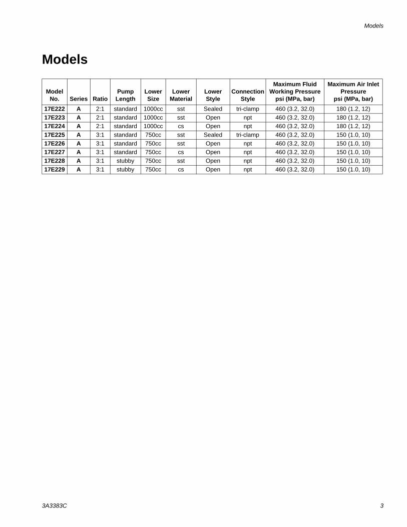
Models
Model No. Series Ratio
Pump Length
Lower Size
Lower Material
Lower Style
Connection Style
Maximum Fluid Working Pressure
psi (MPa, bar)
Maximum Air Inlet Pressure
psi (MPa, bar)
17E222 A 2:1 standard 1000cc sst Sealed tri-clamp 460 (3.2, 32.0) 180 (1.2, 12)17E223 A 2:1 standard 1000cc sst Open npt 460 (3.2, 32.0) 180 (1.2, 12)17E224 A 2:1 standard 1000cc cs Open npt 460 (3.2, 32.0) 180 (1.2, 12)17E225 A 3:1 standard 750cc sst Sealed tri-clamp 460 (3.2, 32.0) 150 (1.0, 10)17E226 A 3:1 standard 750cc sst Open npt 460 (3.2, 32.0) 150 (1.0, 10)17E227 A 3:1 standard 750cc cs Open npt 460 (3.2, 32.0) 150 (1.0, 10)17E228 A 3:1 stubby 750cc sst Open npt 460 (3.2, 32.0) 150 (1.0, 10)17E229 A 3:1 stubby 750cc cs Open npt 460 (3.2, 32.0) 150 (1.0, 10)
Warnings
4 3A3383C
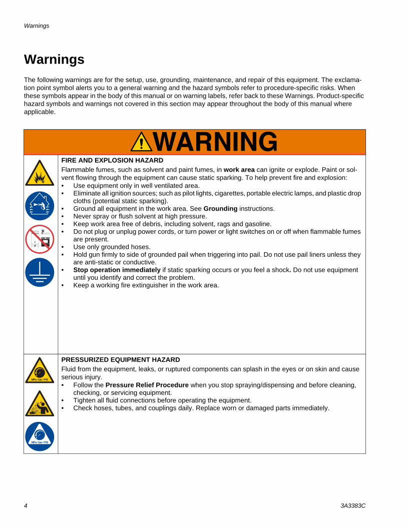
WarningsThe following warnings are for the setup, use, grounding, maintenance, and repair of this equipment. The exclama-tion point symbol alerts you to a general warning and the hazard symbols refer to procedure-specific risks. When these symbols appear in the body of this manual or on warning labels, refer back to these Warnings. Product-specific hazard symbols and warnings not covered in this section may appear throughout the body of this manual where applicable.
FIRE AND EXPLOSION HAZARDFlammable fumes, such as solvent and paint fumes, in work area can ignite or explode. Paint or sol-vent flowing through the equipment can cause static sparking. To help prevent fire and explosion:• Use equipment only in well ventilated area.• Eliminate all ignition sources; such as pilot lights, cigarettes, portable electric lamps, and plastic drop
cloths (potential static sparking). • Ground all equipment in the work area. See Grounding instructions.• Never spray or flush solvent at high pressure.• Keep work area free of debris, including solvent, rags and gasoline.• Do not plug or unplug power cords, or turn power or light switches on or off when flammable fumes
are present.• Use only grounded hoses.• Hold gun firmly to side of grounded pail when triggering into pail. Do not use pail liners unless they
are anti-static or conductive.• Stop operation immediately if static sparking occurs or you feel a shock. Do not use equipment
until you identify and correct the problem.• Keep a working fire extinguisher in the work area.
PRESSURIZED EQUIPMENT HAZARDFluid from the equipment, leaks, or ruptured components can splash in the eyes or on skin and cause serious injury.• Follow the Pressure Relief Procedure when you stop spraying/dispensing and before cleaning,
checking, or servicing equipment. • Tighten all fluid connections before operating the equipment.• Check hoses, tubes, and couplings daily. Replace worn or damaged parts immediately.
Warnings
3A3383C 5
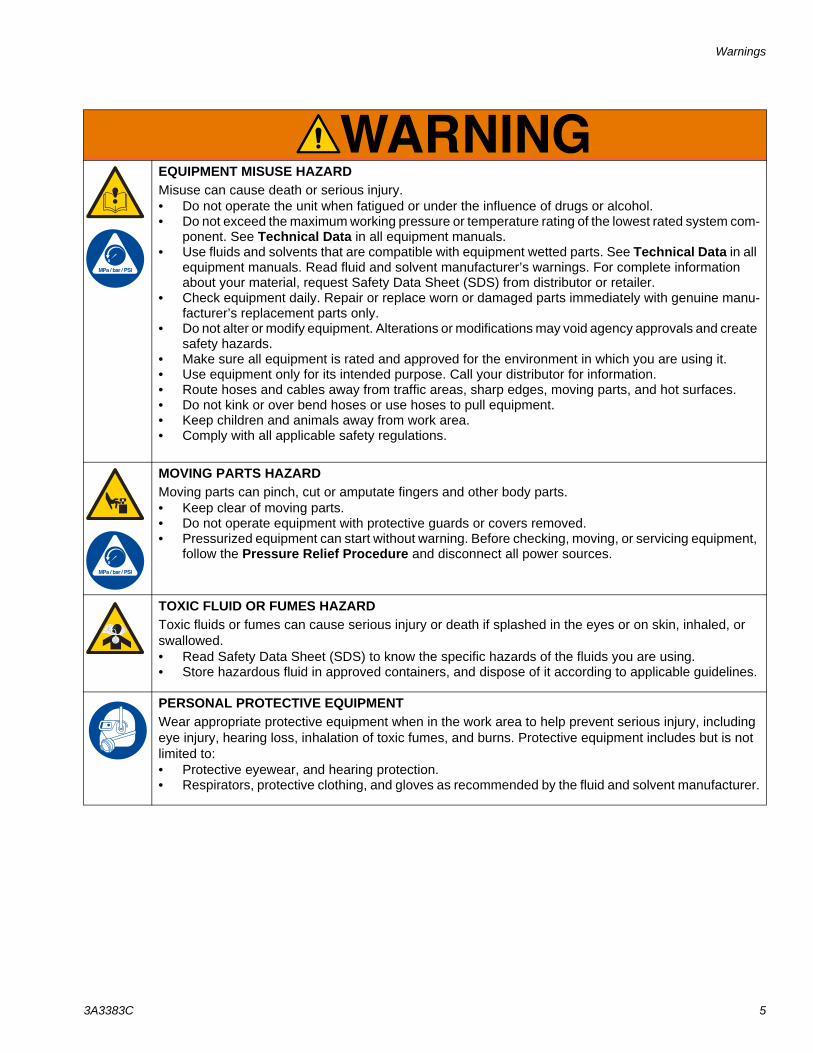
EQUIPMENT MISUSE HAZARDMisuse can cause death or serious injury.• Do not operate the unit when fatigued or under the influence of drugs or alcohol.• Do not exceed the maximum working pressure or temperature rating of the lowest rated system com-
ponent. See Technical Data in all equipment manuals.• Use fluids and solvents that are compatible with equipment wetted parts. See Technical Data in all
equipment manuals. Read fluid and solvent manufacturer’s warnings. For complete information about your material, request Safety Data Sheet (SDS) from distributor or retailer.
• Check equipment daily. Repair or replace worn or damaged parts immediately with genuine manu-facturer’s replacement parts only.
• Do not alter or modify equipment. Alterations or modifications may void agency approvals and create safety hazards.
• Make sure all equipment is rated and approved for the environment in which you are using it.• Use equipment only for its intended purpose. Call your distributor for information.• Route hoses and cables away from traffic areas, sharp edges, moving parts, and hot surfaces.• Do not kink or over bend hoses or use hoses to pull equipment.• Keep children and animals away from work area.• Comply with all applicable safety regulations.
MOVING PARTS HAZARDMoving parts can pinch, cut or amputate fingers and other body parts.• Keep clear of moving parts.• Do not operate equipment with protective guards or covers removed.• Pressurized equipment can start without warning. Before checking, moving, or servicing equipment,
follow the Pressure Relief Procedure and disconnect all power sources.
TOXIC FLUID OR FUMES HAZARDToxic fluids or fumes can cause serious injury or death if splashed in the eyes or on skin, inhaled, or swallowed.• Read Safety Data Sheet (SDS) to know the specific hazards of the fluids you are using.• Store hazardous fluid in approved containers, and dispose of it according to applicable guidelines.
PERSONAL PROTECTIVE EQUIPMENTWear appropriate protective equipment when in the work area to help prevent serious injury, including eye injury, hearing loss, inhalation of toxic fumes, and burns. Protective equipment includes but is not limited to:• Protective eyewear, and hearing protection. • Respirators, protective clothing, and gloves as recommended by the fluid and solvent manufacturer.
Installation
6 3A3383C
Installation
Grounding
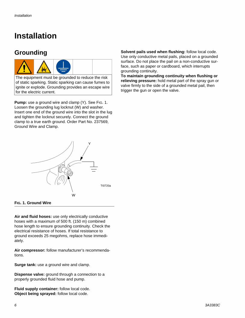
Pump: use a ground wire and clamp (Y). See FIG. 1. Loosen the grounding lug locknut (W) and washer. Insert one end of the ground wire into the slot in the lug and tighten the locknut securely. Connect the ground clamp to a true earth ground. Order Part No. 237569, Ground Wire and Clamp.
Air and fluid hoses: use only electrically conductive hoses with a maximum of 500 ft. (150 m) combined hose length to ensure grounding continuity. Check the electrical resistance of hoses. If total resistance to ground exceeds 25 megohms, replace hose immedi-ately.
Air compressor: follow manufacturer’s recommenda-tions.
Surge tank: use a ground wire and clamp.
Dispense valve: ground through a connection to a properly grounded fluid hose and pump.
Fluid supply container: follow local code.Object being sprayed: follow local code.
Solvent pails used when flushing: follow local code. Use only conductive metal pails, placed on a grounded surface. Do not place the pail on a non-conductive sur-face, such as paper or cardboard, which interrupts grounding continuity.To maintain grounding continuity when flushing or relieving pressure: hold metal part of the spray gun or valve firmly to the side of a grounded metal pail, then trigger the gun or open the valve.
The equipment must be grounded to reduce the risk of static sparking. Static sparking can cause fumes to ignite or explode. Grounding provides an escape wire for the electric current.
FIG. 1. Ground Wire
TI0720a
W
Y
Installation
3A3383C 7
Mounting
Stand MountOrder Part No. 253692 Pump Stand Kit (accessory). Mount the pump in the pump stand and secure with the four screws and lock washers supplied in the kit.
See Mounting Hole Layouts on page 18. Secure the stand to the floor with M19 (5/8 in.) bolts which engage at least 152 mm (6 in.) into the concrete floor to prevent the pump from tipping.
Wall MountOrder Part No. 255143 Wall Bracket Kit (accessory).
1. Ensure the wall is strong enough to support the weight of the pump assembly and accessories, fluid, hoses, and stress caused during pump operation.
2. Ensure that the mounting location has sufficient clearance for easy operator access.
3. Position the wall bracket at a convenient height, ensuring that there is sufficient clearance for the fluid connection line and for servicing the lower.
4. Drill four 7/16 in. (11 mm) holes using the bracket as a template. Use either of the two mounting hole groupings in the bracket. See Mounting Hole Lay-outs, page 18.
5. Bolt the bracket securely to the wall using bolts and washers designed to hold in the wall’s construction.
6. Attach the pump assembly to the mounting bracket.
7. Connect air and fluid hoses.
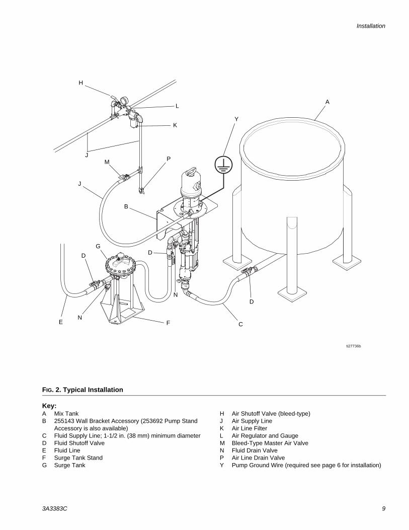
PlumbingSee FIG. 2. Install a fluid shutoff valve (D) between the mix tank (A) and the pump.
When using a stainless steel pump, use stainless steel plumbing to maintain a corrosion-resistant system.
Flush Before Using EquipmentThe equipment was tested with lightweight oil, which is left in the fluid passages to protect parts. To avoid con-taminating your fluid with oil, flush the equipment with a compatible solvent before using the equipment. See Flushing, page 11.
Installation
8 3A3383C
AccessoriesInstall the following accessories in the order shown in FIG. 2, using adapters as necessary.
Air Line• Bleed-type master air valve (M): required in your
system to relieve air trapped between it and the air motor when the valve is closed.
• Pump air regulator (L): to control pump speed and outlet pressure. Locate close to the pump.
• Air line filter (K): removes harmful dirt and mois-ture from compressed air supply.
• Second bleed-type air valve (H): isolates air line accessories for servicing. Locate upstream from all other air line accessories.
Fluid Line• Fluid filter: with a 60 mesh (250 micron) stainless
steel element to filter particles from the fluid as it leaves the pump.
• Fluid drain valve (N): required in your system, to relieve fluid pressure in the hose and gun.
• Fluid shutoff valve (D): shuts off fluid flow.
Trapped air can cause the pump to cycle unexpect-edly, which could result in serious injury from splash-ing or moving parts. Be sure the valve is easily accessible from the pump and located downstream from the air regulator. Be sure the air bleed hole points away from the operator.
To help prevent fluid over pressurization, do not exceed the maximum air inlet pressure rating to the air motor (see page 2). If you can apply more than the maximum air input pressure to the system, install a safety relief valve between the bleed-type master air valve and the air motor. The safety relief valve must be set to open if the air inlet pressure to the motor exceeds the motor rating.
Installation
3A3383C 9
Key:A Mix TankB 255143 Wall Bracket Accessory (253692 Pump Stand
Accessory is also available)C Fluid Supply Line; 1-1/2 in. (38 mm) minimum diameterD Fluid Shutoff ValveE Fluid LineF Surge Tank StandG Surge Tank
H Air Shutoff Valve (bleed-type)J Air Supply LineK Air Line FilterL Air Regulator and GaugeM Bleed-Type Master Air ValveN Fluid Drain ValveP Air Line Drain ValveY Pump Ground Wire (required see page 6 for installation)
FIG. 2. Typical Installation
A
B
F
G
D
H
M
K
L
N
D
CE
PJ
Y
J
N
D
Operation
10 3A3383C
Operation
Pressure Relief ProcedureFollow the Pressure Relief Procedure when-ever you see this symbol.
1. Close the bleed-type master air valve (M).
2. Open the dispensing valve, if used.
3. Open all fluid drain valves (N) in the system, having a waste container ready to catch drainage. Leave drain valve(s) open until you are ready to pump again.
Prime the Pump1. Fill the wet cup with Throat Seal Liquid (TSL).
NOTE: Sealed 4 ball lowers with bellows do not require TSL.
NOTE: During operation the TSL level in the wet cup will fluctuate slightly at pump changeover.
2. Close pump air regulator (L) by turning knob coun-terclockwise reducing pressure to zero. Close bleed-type air valve (M). Also verify that all drain valves (N) are closed.
3. Connect air line (J) to bleed type air valve (M).
4. Check that all fittings throughout system are tight-ened securely.
5. Connect the fluid supply line (C) from the mix tank shutoff valve (D) to the pump.
6. Connect the fluid line (E) to the pump outlet.
7. Open bleed-type air valve (M). Slowly turn pump air regulator (L) clockwise, increasing pressure until pump starts.
8. Cycle pump slowly until all air is pushed out and pump and hoses are fully primed.
9. Close the fluid shutoff valve (D) downstream of the pump. The pump should stall against pressure.
NOTE: In a circulation system, the pump operates con-tinuously until the power supply is shut off. In a direct-supply system, the pump starts when the dis-pense valve is opened, and stops when the dispense valve is closed.
Stop Pump at Bottom of Stroke
Relieve the pressure when you stop the pump for any reason. Stop the pump on the down stroke, before the air motor changes over.
Shutdown
Follow the Pressure Relief Procedure, page 10.
Always flush the pump before the fluid dries on the dis-placement rod. See Flushing on page 11.
This equipment stays pressurized until pressure is manually relieved. To help prevent serious injury from splashing fluid and moving parts, follow the Pressure Relief Procedure when you stop spraying and before cleaning, checking, or servicing the equipment.
NOTICE
Failure to stop the pump at the bottom of its stroke allows fluid to dry on the piston rod, which can dam-age the throat seal.
Maintenance
3A3383C 11
Maintenance
Preventive Maintenance ScheduleThe operating conditions of your particular system determine how often maintenance is required. Establish a preventive maintenance schedule by recording when and what kind of maintenance is needed, and then determine a regular schedule for checking your system. Your maintenance schedule should include the follow-ing:
Flushing
• Flush before changing colors, before fluid can dry in the equipment, at the end of the day, before storing, and before repairing equipment.
• Flush at the lowest pressure possible. Check con-nectors for leaks and tighten as necessary.
• Flush with a fluid that is compatible with the fluid being dispensed and the equipment wetted parts.
Air Line FilterDrain and clean as necessary.
Mix Tank VolumeDo not let the mix tank run dry. When the tank is empty, the pump demands more power as it tries to suck in some fluid. This causes the pump to run too fast, which can seriously damage the pump.
Stall TestPerform a stall test periodically to ensure the piston seal is in good working condition and prevent system pres-surization:
Close the fluid shutoff valve (D) closest to the pump on the down stroke and be sure that the pump stalls. Open the fluid shutoff valve to restart the pump. Close the fluid shutoff valve (D) closest to the pump on the upstroke and be sure that the pump stalls.
Stop the pump on the down stroke, before the air motor changes over.
Changing the TSL On Wet Cup ModelsOn Wet Cup Models check the condition of the TSL and the level in the wet cup every week, minimum. TSL should be changed at least every month.
To avoid fire and explosion, always ground equipment and waste container. To avoid static sparking and injury from splashing, always flush at the lowest pos-sible pressure.
NOTICE
Do not allow the pump to run quickly for a long period of time as this may damage the seal.
NOTICE
Failure to stop the pump at the bottom of its stroke allows fluid to dry on the piston rod, which can dam-age the throat seal when the pump is restarted.
Troubleshooting
12 3A3383C
Troubleshooting
Problem Cause Solution
Pump output low on both strokes. Restricted air supply lines. Clear any obstructions; be sure all shutoff valves are open; increase pressure, but do not exceed maximum working pres-sure.
Exhausted fluid supply. Refill and reprime pump.
Clogged fluid outlet line, valves, etc. Clear.
Worn piston packing. Replace. See lower manual.
Pump output low on only one stroke. Held open or worn ball check valves. Check and repair.
Worn piston packings. Replace. See lower manual.
No output. Improperly installed ball check valves. Check and repair.
Pump operates erratically. Exhausted fluid supply. Refill and reprime pump.
Held open or worn ball check valves. Check and repair.
Worn piston packing. Replace. See lower manual.
Pump will not operate. Restricted air supply lines. Clear any obstructions; be sure all shut off valves are open; increase pressure, but do not exceed maximum working pressure.
Exhausted fluid supply. Refill and reprime pump.
Clogged fluid outlet line, valves, etc. Clear.
Damaged air motor. See air motor manual.
Fluid dried on piston rod. Disassemble and clean pump. See lower manual. In future, stop pump at bottom of stroke.
Repair
3A3383C 13
Repair
Disassembly
1. Follow the Pressure Relief Procedure, page 10.
2. Disconnect the hoses from the lower and plug the ends to prevent fluid contamination.
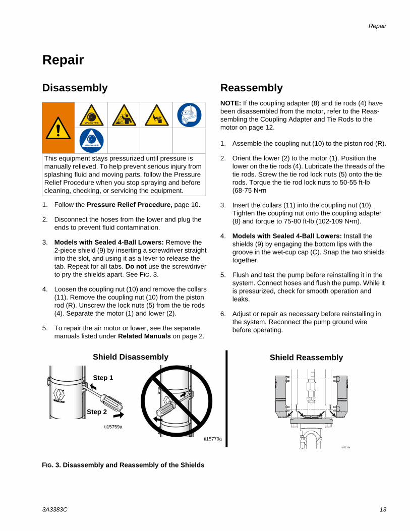
3. Models with Sealed 4-Ball Lowers: Remove the 2-piece shield (9) by inserting a screwdriver straight into the slot, and using it as a lever to release the tab. Repeat for all tabs. Do not use the screwdriver to pry the shields apart. See FIG. 3.
4. Loosen the coupling nut (10) and remove the collars (11). Remove the coupling nut (10) from the piston rod (R). Unscrew the lock nuts (5) from the tie rods (4). Separate the motor (1) and lower (2).
5. To repair the air motor or lower, see the separate manuals listed under Related Manuals on page 2.
ReassemblyNOTE: If the coupling adapter (8) and tie rods (4) have been disassembled from the motor, refer to the Reas-sembling the Coupling Adapter and Tie Rods to the motor on page 12.
1. Assemble the coupling nut (10) to the piston rod (R).
2. Orient the lower (2) to the motor (1). Position the lower on the tie rods (4). Lubricate the threads of the tie rods. Screw the tie rod lock nuts (5) onto the tie rods. Torque the tie rod lock nuts to 50-55 ft-lb (68-75 N•m
3. Insert the collars (11) into the coupling nut (10). Tighten the coupling nut onto the coupling adapter (8) and torque to 75-80 ft-lb (102-109 N•m).
4. Models with Sealed 4-Ball Lowers: Install the shields (9) by engaging the bottom lips with the groove in the wet-cup cap (C). Snap the two shields together.
5. Flush and test the pump before reinstalling it in the system. Connect hoses and flush the pump. While it is pressurized, check for smooth operation and leaks.
6. Adjust or repair as necessary before reinstalling in the system. Reconnect the pump ground wire before operating.
This equipment stays pressurized until pressure is manually relieved. To help prevent serious injury from splashing fluid and moving parts, follow the Pressure Relief Procedure when you stop spraying and before cleaning, checking, or servicing the equipment.
FIG. 3. Disassembly and Reassembly of the Shields
ti15759a
Shield Disassembly
ti15770a
Shield Reassembly
Step 1
Step 2
Repair
14 3A3383C
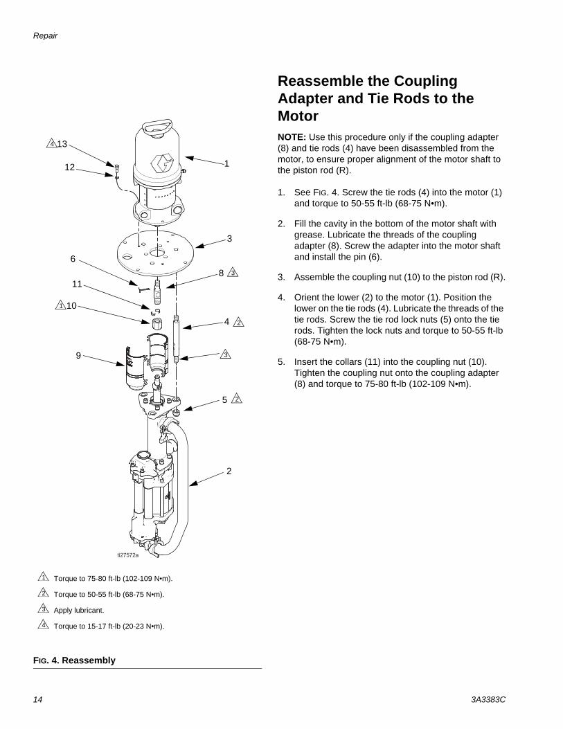
Reassemble the Coupling Adapter and Tie Rods to the MotorNOTE: Use this procedure only if the coupling adapter (8) and tie rods (4) have been disassembled from the motor, to ensure proper alignment of the motor shaft to the piston rod (R).
1. See FIG. 4. Screw the tie rods (4) into the motor (1) and torque to 50-55 ft-lb (68-75 N•m).
2. Fill the cavity in the bottom of the motor shaft with grease. Lubricate the threads of the coupling adapter (8). Screw the adapter into the motor shaft and install the pin (6).
3. Assemble the coupling nut (10) to the piston rod (R).
4. Orient the lower (2) to the motor (1). Position the lower on the tie rods (4). Lubricate the threads of the tie rods. Screw the tie rod lock nuts (5) onto the tie rods. Tighten the lock nuts and torque to 50-55 ft-lb (68-75 N•m).
5. Insert the collars (11) into the coupling nut (10). Tighten the coupling nut onto the coupling adapter (8) and torque to 75-80 ft-lb (102-109 N•m).
FIG. 4. Reassembly
1
9
2
11
3
10
8
5
4
6
13
12
Torque to 75-80 ft-lb (102-109 N•m).
Torque to 50-55 ft-lb (68-75 N•m).
Apply lubricant.
Torque to 15-17 ft-lb (20-23 N•m).
1
2
3
4
4
2
2
3
3
1
Parts
3A3383C 15
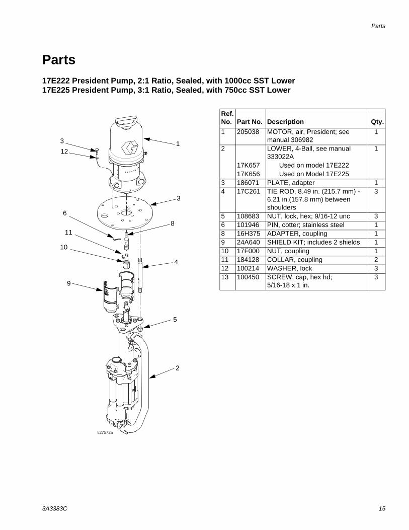
Parts17E222 President Pump, 2:1 Ratio, Sealed, with 1000cc SST Lower17E225 President Pump, 3:1 Ratio, Sealed, with 750cc SST Lower
1
9
2
11
3
10
8
5
4
6
3
12
Ref. No. Part No. Description Qty.1 205038 MOTOR, air, President; see
manual 3069821
2 LOWER, 4-Ball, see manual 333022A
1
17K657 Used on model 17E22217K656 Used on Model 17E225
3 186071 PLATE, adapter 14 17C261 TIE ROD, 8.49 in. (215.7 mm) -
6.21 in.(157.8 mm) between shoulders
3
5 108683 NUT, lock, hex; 9/16-12 unc 36 101946 PIN, cotter; stainless steel 18 16H375 ADAPTER, coupling 19 24A640 SHIELD KIT; includes 2 shields 110 17F000 NUT, coupling 111 184128 COLLAR, coupling 212 100214 WASHER, lock 313 100450 SCREW, cap, hex hd;
5/16-18 x 1 in. 3
Parts
16 3A3383C
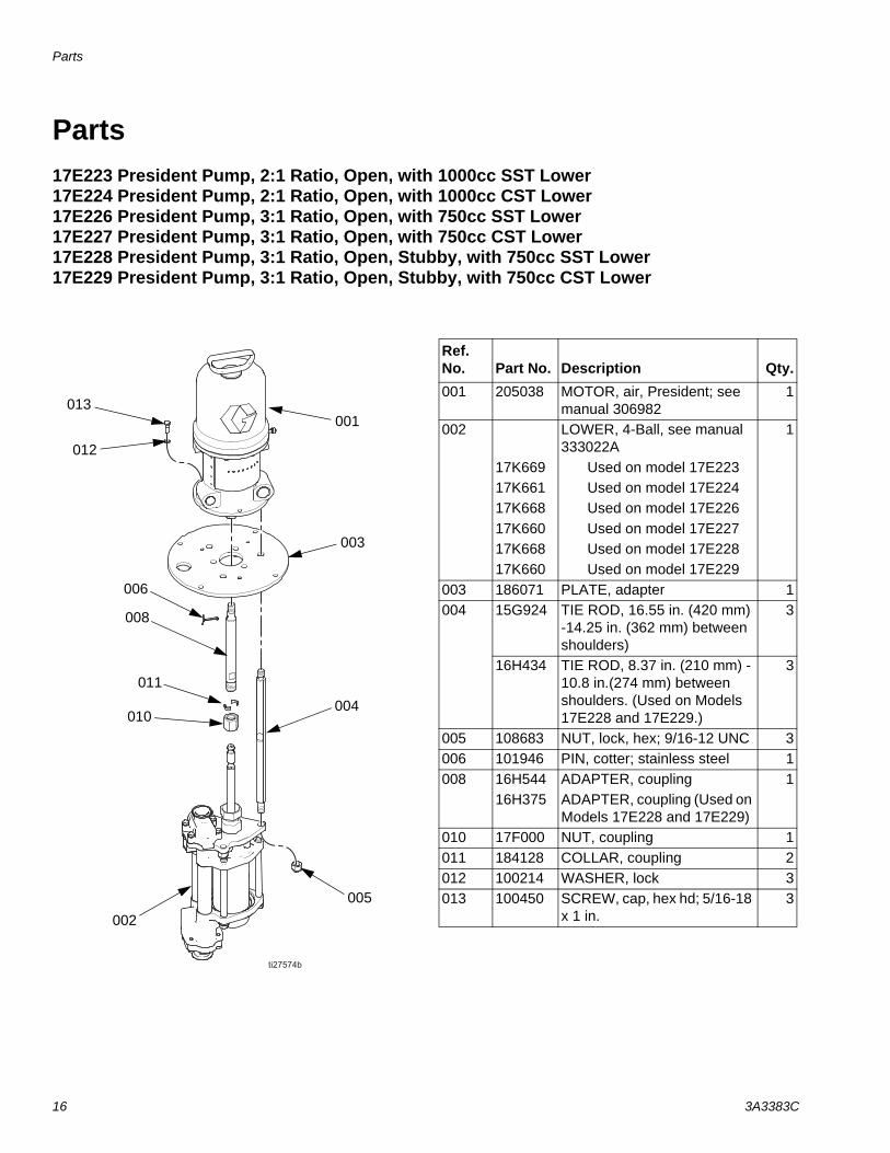
Parts17E223 President Pump, 2:1 Ratio, Open, with 1000cc SST Lower 17E224 President Pump, 2:1 Ratio, Open, with 1000cc CST Lower17E226 President Pump, 3:1 Ratio, Open, with 750cc SST Lower17E227 President Pump, 3:1 Ratio, Open, with 750cc CST Lower17E228 President Pump, 3:1 Ratio, Open, Stubby, with 750cc SST Lower17E229 President Pump, 3:1 Ratio, Open, Stubby, with 750cc CST Lower
001
002
011
003
004
008
005
010
006
013
012
Ref. No. Part No. Description Qty.001 205038 MOTOR, air, President; see
manual 3069821
002 LOWER, 4-Ball, see manual 333022A
1
17K669 Used on model 17E22317K661 Used on model 17E22417K668 Used on model 17E22617K660 Used on model 17E22717K668 Used on model 17E22817K660 Used on model 17E229
003 186071 PLATE, adapter 1004 15G924 TIE ROD, 16.55 in. (420 mm)
-14.25 in. (362 mm) between shoulders)
3
16H434 TIE ROD, 8.37 in. (210 mm) - 10.8 in.(274 mm) between shoulders. (Used on Models 17E228 and 17E229.)
3
005 108683 NUT, lock, hex; 9/16-12 UNC 3006 101946 PIN, cotter; stainless steel 1008 16H544 ADAPTER, coupling 1
16H375 ADAPTER, coupling (Used on Models 17E228 and 17E229)
010 17F000 NUT, coupling 1011 184128 COLLAR, coupling 2012 100214 WASHER, lock 3013 100450 SCREW, cap, hex hd; 5/16-18
x 1 in. 3
Dimensions
3A3383C 17
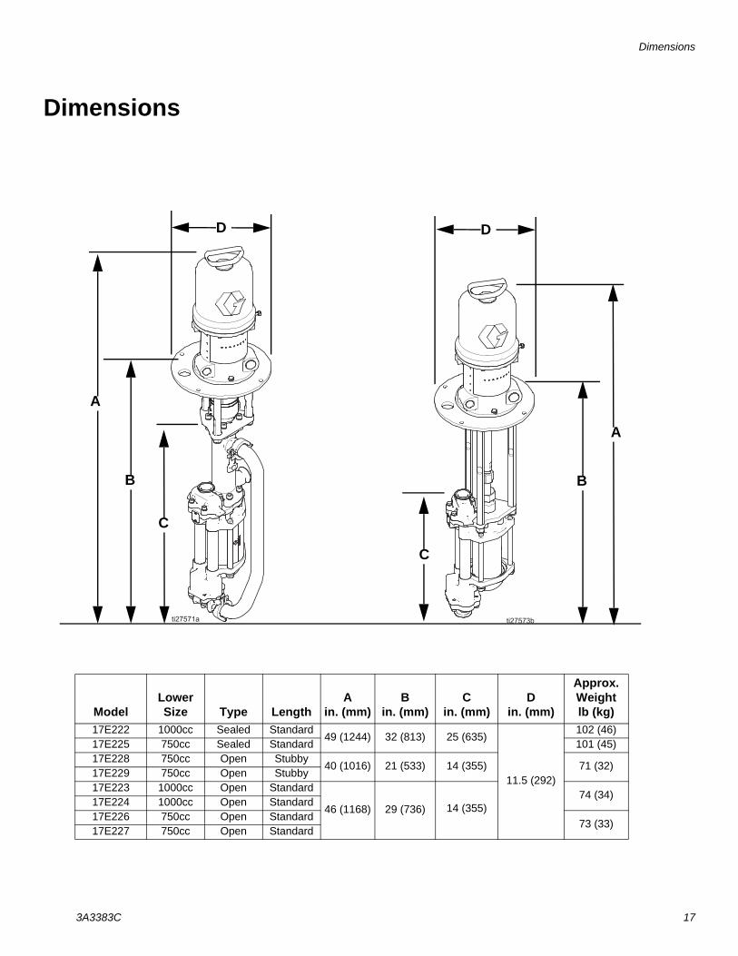
Dimensions
A
B
C
D
A
B
C
D
ModelLower Size Type Length
Ain. (mm)
Bin. (mm)
Cin. (mm)
Din. (mm)
Approx. Weightlb (kg)
17E222 1000cc Sealed Standard49 (1244) 32 (813) 25 (635)
11.5 (292)
102 (46)17E225 750cc Sealed Standard 101 (45)17E228 750cc Open Stubby
40 (1016) 21 (533) 14 (355) 71 (32)17E229 750cc Open Stubby17E223 1000cc Open Standard
46 (1168) 29 (736) 14 (355)74 (34)
17E224 1000cc Open Standard17E226 750cc Open Standard
73 (33)17E227 750cc Open Standard
Mounting Hole Layouts
18 3A3383C
Mounting Hole Layouts
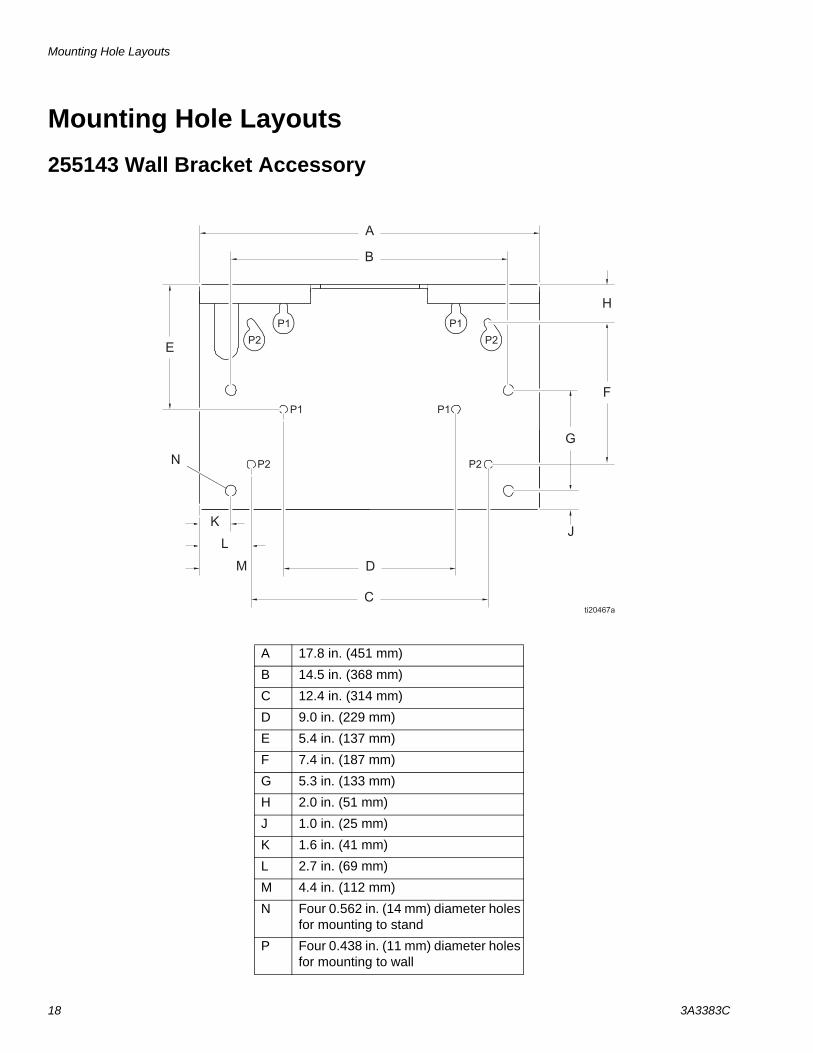
255143 Wall Bracket Accessory
A 17.8 in. (451 mm)
B 14.5 in. (368 mm)
C 12.4 in. (314 mm)
D 9.0 in. (229 mm)
E 5.4 in. (137 mm)
F 7.4 in. (187 mm)
G 5.3 in. (133 mm)
H 2.0 in. (51 mm)
J 1.0 in. (25 mm)
K 1.6 in. (41 mm)
L 2.7 in. (69 mm)
M 4.4 in. (112 mm)
N Four 0.562 in. (14 mm) diameter holes for mounting to stand
P Four 0.438 in. (11 mm) diameter holes for mounting to wall
Mounting Hole Layouts
3A3383C 19
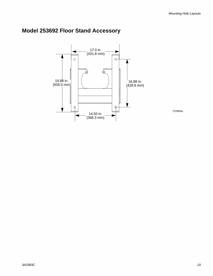
Model 253692 Floor Stand Accessory
16.88 in. (428.8 mm)
14.50 in. (368.3 mm)
17.0 in. (431.8 mm)
19.88 in. (505.0 mm)
TI15859a
Performance Charts
20 3A3383C
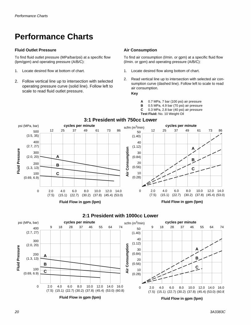
Performance Charts Fluid Outlet Pressure
To find fluid outlet pressure (MPa/bar/psi) at a specific flow (lpm/gpm) and operating pressure (A/B/C):
1. Locate desired flow at bottom of chart.
2. Follow vertical line up to intersection with selected operating pressure curve (solid line). Follow left to scale to read fluid outlet pressure.
Air Consumption
To find air consumption (l/min. or gpm) at a specific fluid flow (l/min. or gpm) and operating pressure (A/B/C):
1. Locate desired flow along bottom of chart.
2. Read vertical line up to intersection with selected air con-sumption curve (dashed line). Follow left to scale to read air consumption.Key
A 0.7 MPa, 7 bar (100 psi) air pressureB 0.5 MPa, 4.9 bar (70 psi) air pressure C 0.3 MPa, 2.8 bar (40 psi) air pressure Test Fluid: No. 10 Weight Oil
3:1 President with 750cc Lower
500(3.5, 35)
A
B
A
B
C
Flui
d P
ress
ure
psi (MPa, bar)
300(2.0, 20)
200(1.3, 13)
100(0.69, 6.9)
Air
Con
sum
ptio
n
40(1.12)
C
0
30(0.84)
20(0.56)
10(0.28)
scfm (m3/min)50
(1.40)
2.0(7.5)
6.0(22.7)
10.0(37.8)
14.0(53.0)
4.0(15.1)
8.0(30.2)
12.0(45.4)
Fluid Flow in gpm (lpm)
0 2.0(7.5)
6.0(22.7)
10.0(37.8)
14.0(53.0)
4.0(15.1)
8.0(30.2)
12.0(45.4)
Fluid Flow in gpm (lpm)
400(2.7, 27)
2:1 President with 1000cc Lower
400(2.7, 27)
2.0(7.5)
6.0(22.7)
10.0(37.8)
14.0(53.0)
4.0(15.1)
8.0(30.2)
12.0(45.4)
A
B
A
B
CFlui
d P
ress
ure
psi (MPa, bar)
300(2.0, 20)
200(1.3, 13)
100(0.69, 6.9)
0
Fluid Flow in gpm (lpm)
Air
Con
sum
ptio
n
40(1.12)
C
0
30(0.84)
20(0.56)
10(0.28)
16.0(60.8)
50(1.40)
2.0(7.5)
6.0(22.7)
10.0(37.8)
14.0(53.0)
4.0(15.1)
8.0(30.2)
12.0(45.4)
Fluid Flow in gpm (lpm)
16.0(60.8)
scfm (m3/min)
12 25 37 49 61 73 86cycles per minute
12 25 37 49 61 73 86cycles per minute
9 18 28 37 46 55 64cycles per minute
749 18 28 37 46 55 64cycles per minute
74
Technical Data
3A3383C 21
Technical Data
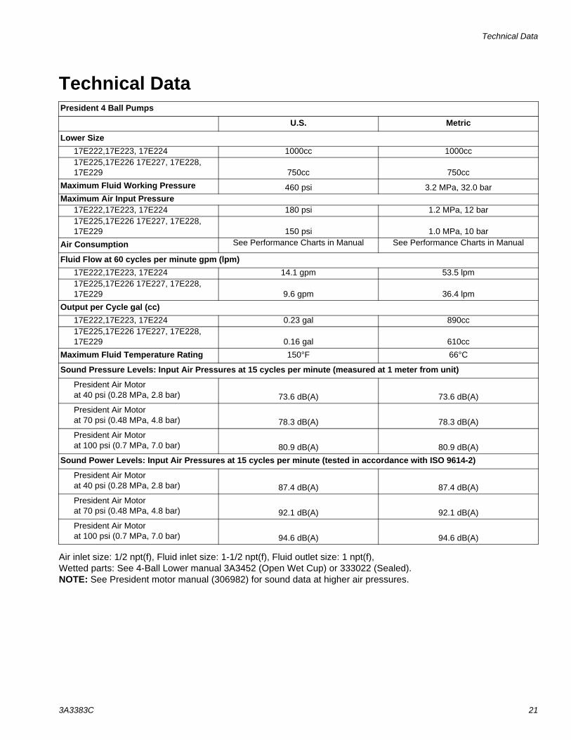
Air inlet size: 1/2 npt(f), Fluid inlet size: 1-1/2 npt(f), Fluid outlet size: 1 npt(f), Wetted parts: See 4-Ball Lower manual 3A3452 (Open Wet Cup) or 333022 (Sealed).NOTE: See President motor manual (306982) for sound data at higher air pressures.
President 4 Ball Pumps
U.S. Metric
Lower Size17E222,17E223, 17E224 1000cc 1000cc17E225,17E226 17E227, 17E228, 17E229 750cc 750cc
Maximum Fluid Working Pressure 460 psi 3.2 MPa, 32.0 barMaximum Air Input Pressure
17E222,17E223, 17E224 180 psi 1.2 MPa, 12 bar 17E225,17E226 17E227, 17E228, 17E229 150 psi 1.0 MPa, 10 bar
Air Consumption See Performance Charts in Manual See Performance Charts in Manual
Fluid Flow at 60 cycles per minute gpm (lpm)17E222,17E223, 17E224 14.1 gpm 53.5 lpm17E225,17E226 17E227, 17E228, 17E229 9.6 gpm 36.4 lpm
Output per Cycle gal (cc)17E222,17E223, 17E224 0.23 gal 890cc17E225,17E226 17E227, 17E228, 17E229 0.16 gal 610cc
Maximum Fluid Temperature Rating 150°F 66°C
Sound Pressure Levels: Input Air Pressures at 15 cycles per minute (measured at 1 meter from unit)
President Air Motorat 40 psi (0.28 MPa, 2.8 bar) 73.6 dB(A) 73.6 dB(A)
President Air Motorat 70 psi (0.48 MPa, 4.8 bar) 78.3 dB(A) 78.3 dB(A)
President Air Motorat 100 psi (0.7 MPa, 7.0 bar) 80.9 dB(A) 80.9 dB(A)
Sound Power Levels: Input Air Pressures at 15 cycles per minute (tested in accordance with ISO 9614-2)
President Air Motorat 40 psi (0.28 MPa, 2.8 bar) 87.4 dB(A) 87.4 dB(A)
President Air Motorat 70 psi (0.48 MPa, 4.8 bar) 92.1 dB(A) 92.1 dB(A)
President Air Motorat 100 psi (0.7 MPa, 7.0 bar) 94.6 dB(A) 94.6 dB(A)

All written and visual data contained in this document reflects the latest product information available at the time of publication. Graco reserves the right to make changes at any time without notice.
Original instructions. This manual contains English. MM 3A3383
Graco Headquarters: MinneapolisInternational Offices: Belgium, China, Japan, Korea
GRACO INC. AND SUBSIDIARIES • P.O. BOX 1441 • MINNEAPOLIS MN 55440-1441 • USA
Copyright 2015, Graco Inc. All Graco manufacturing locations are registered to ISO 9001.www.graco.com
Revision C, July 2017
Graco Standard WarrantyGraco warrants all equipment referenced in this document which is manufactured by Graco and bearing its name to be free from defects in material and workmanship on the date of sale to the original purchaser for use. With the exception of any special, extended, or limited warranty published by Graco, Graco will, for a period of twelve months from the date of sale, repair or replace any part of the equipment determined by Graco to be defective. This warranty applies only when the equipment is installed, operated and maintained in accordance with Graco’s written recommendations.
This warranty does not cover, and Graco shall not be liable for general wear and tear, or any malfunction, damage or wear caused by faulty installation, misapplication, abrasion, corrosion, inadequate or improper maintenance, negligence, accident, tampering, or substitution of non-Graco component parts. Nor shall Graco be liable for malfunction, damage or wear caused by the incompatibility of Graco equipment with structures, accessories, equipment or materials not supplied by Graco, or the improper design, manufacture, installation, operation or maintenance of structures, accessories, equipment or materials not supplied by Graco.
This warranty is conditioned upon the prepaid return of the equipment claimed to be defective to an authorized Graco distributor for verification of the claimed defect. If the claimed defect is verified, Graco will repair or replace free of charge any defective parts. The equipment will be returned to the original purchaser transportation prepaid. If inspection of the equipment does not disclose any defect in material or workmanship, repairs will be made at a reasonable charge, which charges may include the costs of parts, labor, and transportation.
THIS WARRANTY IS EXCLUSIVE, AND IS IN LIEU OF ANY OTHER WARRANTIES, EXPRESS OR IMPLIED, INCLUDING BUT NOT LIMITED TO WARRANTY OF MERCHANTABILITY OR WARRANTY OF FITNESS FOR A PARTICULAR PURPOSE.
Graco’s sole obligation and buyer’s sole remedy for any breach of warranty shall be as set forth above. The buyer agrees that no other remedy (including, but not limited to, incidental or consequential damages for lost profits, lost sales, injury to person or property, or any other incidental or consequential loss) shall be available. Any action for breach of warranty must be brought within two (2) years of the date of sale.
GRACO MAKES NO WARRANTY, AND DISCLAIMS ALL IMPLIED WARRANTIES OF MERCHANTABILITY AND FITNESS FOR A PARTICULAR PURPOSE, IN CONNECTION WITH ACCESSORIES, EQUIPMENT, MATERIALS OR COMPONENTS SOLD BUT NOT MANUFACTURED BY GRACO. These items sold, but not manufactured by Graco (such as electric motors, switches, hose, etc.), are subject to the warranty, if any, of their manufacturer. Graco will provide purchaser with reasonable assistance in making any claim for breach of these warranties.
In no event will Graco be liable for indirect, incidental, special or consequential damages resulting from Graco supplying equipment hereunder, or the furnishing, performance, or use of any products or other goods sold hereto, whether due to a breach of contract, breach of warranty, the negligence of Graco, or otherwise.
FOR GRACO CANADA CUSTOMERSThe Parties acknowledge that they have required that the present document, as well as all documents, notices and legal proceedings entered into, given or instituted pursuant hereto or relating directly or indirectly hereto, be drawn up in English. Les parties reconnaissent avoir convenu que la rédaction du présente document sera en Anglais, ainsi que tous documents, avis et procédures judiciaires exécutés, donnés ou intentés, à la suite de ou en rapport, directement ou indirectement, avec les procédures concernées.
Graco InformationFor the latest information about Graco products, visit www.graco.com.For patent information, see www.graco.com/patents.
TO PLACE AN ORDER, contact your Graco distributor or call to identify the nearest distributor.Phone: 612-623-6921 or Toll Free: 1-800-328-0211 Fax: 612-378-3505