Presented by: Kenneth J. Thornton, P.G. PENNDOT … · Presented by: Kenneth J. Thornton, ... 6...
52
Tarrtown Bridge Project Overview Presented by: Presented by: Kenneth J. Thornton, P.G. Kenneth J. Thornton, P.G. PENNDOT SEM Program Office PENNDOT SEM Program Office Apex
Transcript of Presented by: Kenneth J. Thornton, P.G. PENNDOT … · Presented by: Kenneth J. Thornton, ... 6...
Tarrtown Bridge Project Overview
Presented by:Presented by:
Kenneth J. Thornton, P.G.Kenneth J. Thornton, P.G.PENNDOT SEM Program OfficePENNDOT SEM Program Office
Apex

PENNDOT-PADEP Collaboration
First scrap tire recycling project in PA.First scrap tire recycling project in PA.750,000 tires (7,500 tons) used750,000 tires (7,500 tons) usedScrap tires from 4 community collection Scrap tires from 4 community collection days, river sweeps, 6 abandoned tire piles, days, river sweeps, 6 abandoned tire piles, PADEP consent ordersPADEP consent ordersShredded tires used as lightweight Shredded tires used as lightweight geotechnical fill (50 1b/ftgeotechnical fill (50 1b/ft33))Joint funding provided by PADEPJoint funding provided by PADEP

Project Stakeholders
PENNDOT Engineering District 10PENNDOT Engineering District 10PENNDOT Central Office / ApexPENNDOT Central Office / ApexPADEPPADEPPADEP Waste Tire Pile Grant RecipientsPADEP Waste Tire Pile Grant RecipientsAllegheny Energy, Watershed OrganizationsAllegheny Energy, Watershed OrganizationsWestern PA CountiesWestern PA CountiesA&L Construction (Bridge Contractor)A&L Construction (Bridge Contractor)Power Contracting (Shredding)Power Contracting (Shredding)

Tarrtown Project Locations
Bridge Site
Shredding Site

PADEP Cochran Site (250,000 tires)Initial Conditions

PADEP Cochran Site (250,000 tires)Remediation Completed
After removal activity, site owner responsible for landscaping
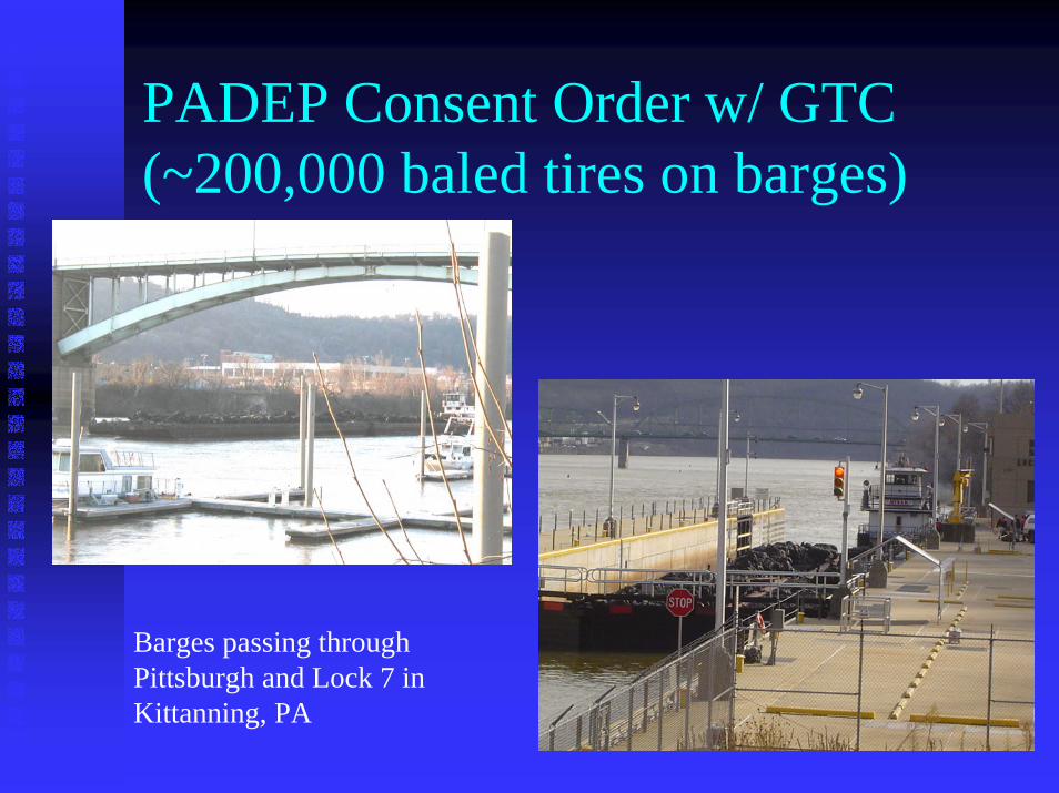
PADEP Consent Order w/ GTC (~200,000 baled tires on barges)
Barges passing throughPittsburgh and Lock 7 in Kittanning, PA

GTC baled tires recycled at TarrtownBaled tires unloaded and ready for transport to shredding site for de-baling and shredding.
Each bale contains approximately 100 tires.

PENNDOT Tire Shredding SiteTarrtown, Armstrong County
For processing & stockpiling 750,000 tires, approx. 6 acres was required
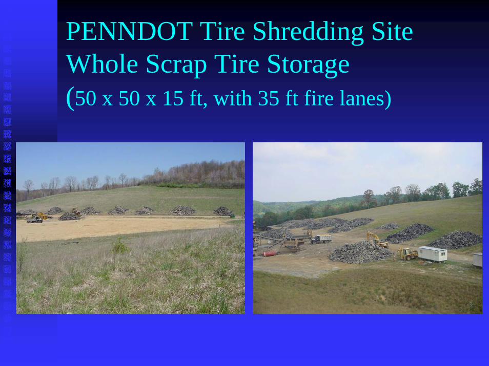
PENNDOT Tire Shredding SiteWhole Scrap Tire Storage(50 x 50 x 15 ft, with 35 ft fire lanes)

Project specifications
Tire ShredsTire ShredsLength Length GradationGradationDeleterious materialsDeleterious materialsFree SteelFree SteelExposed SteelExposed Steel
EmbankmentEmbankmentInstrumentationInstrumentation
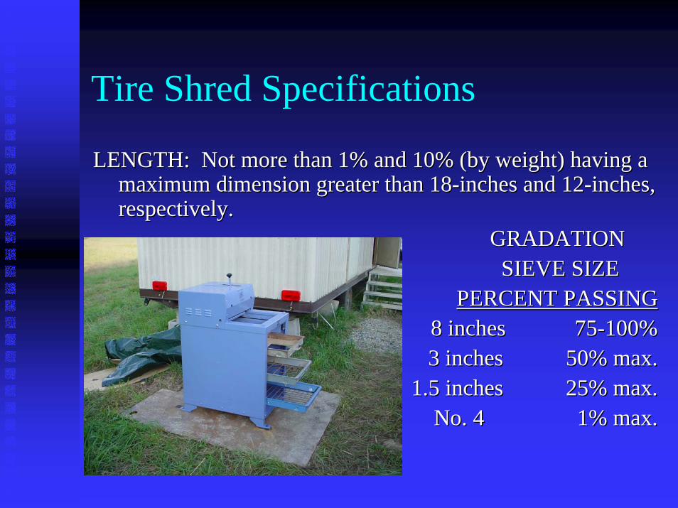
Tire Shred Specifications
LENGTH: Not more than 1% and 10% (by weight) having a LENGTH: Not more than 1% and 10% (by weight) having a maximum dimension greater than 18maximum dimension greater than 18--inches and 12inches and 12--inches, inches, respectively.respectively.
GRADATION GRADATION SIEVE SIZESIEVE SIZE
PERCENT PASSINGPERCENT PASSING8 inches8 inches 7575--100%100%3 inches3 inches 50% max.50% max.
1.5 inches1.5 inches 25% max.25% max.No. 4No. 4 1% max.1% max.
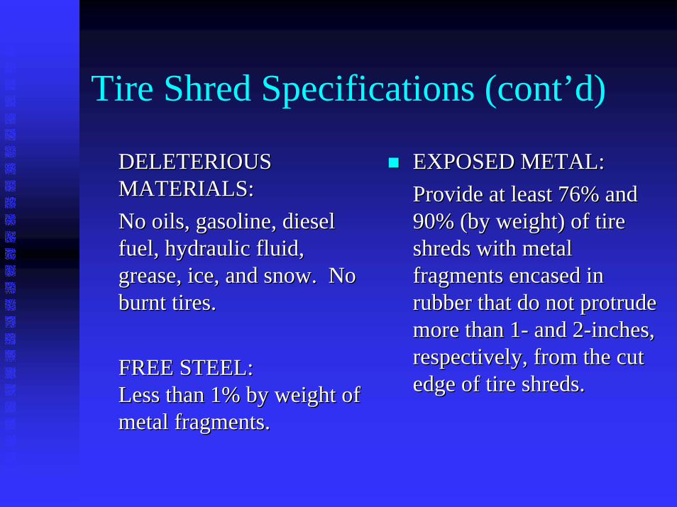
Tire Shred Specifications (cont’d)
DELETERIOUS DELETERIOUS MATERIALS: MATERIALS: No oils, gasoline, diesel No oils, gasoline, diesel fuel, hydraulic fluid, fuel, hydraulic fluid, grease, ice, and snow. No grease, ice, and snow. No burnt tires.burnt tires.
FREE STEEL:FREE STEEL:Less than 1% by weight of Less than 1% by weight of metal fragments.
EXPOSED METAL: EXPOSED METAL: Provide at least 76% and Provide at least 76% and 90% (by weight) of tire 90% (by weight) of tire shreds with metal shreds with metal fragments encased in fragments encased in rubber that do not protrude rubber that do not protrude more than 1more than 1-- and 2and 2--inches, inches, respectively, from the cut respectively, from the cut edge of tire shreds.edge of tire shreds.
metal fragments.

Unloading-Grapple excavatorsTo minimize soil inclusion with scrap tires, during handling and processinggrapple attachments are preferred.

Unloading-Grapple loaders
Custom grapple attachmentFor loaders.

De-rimming
Lead counter weights removed from rims prior to recycling rims as scrap metal.

Tire Shredding EquipmentThe PennDOT-approved tire shred requires a process not a single machine, in much the same way as approved aggregates require crushing, screening, washing, quality control, etc.
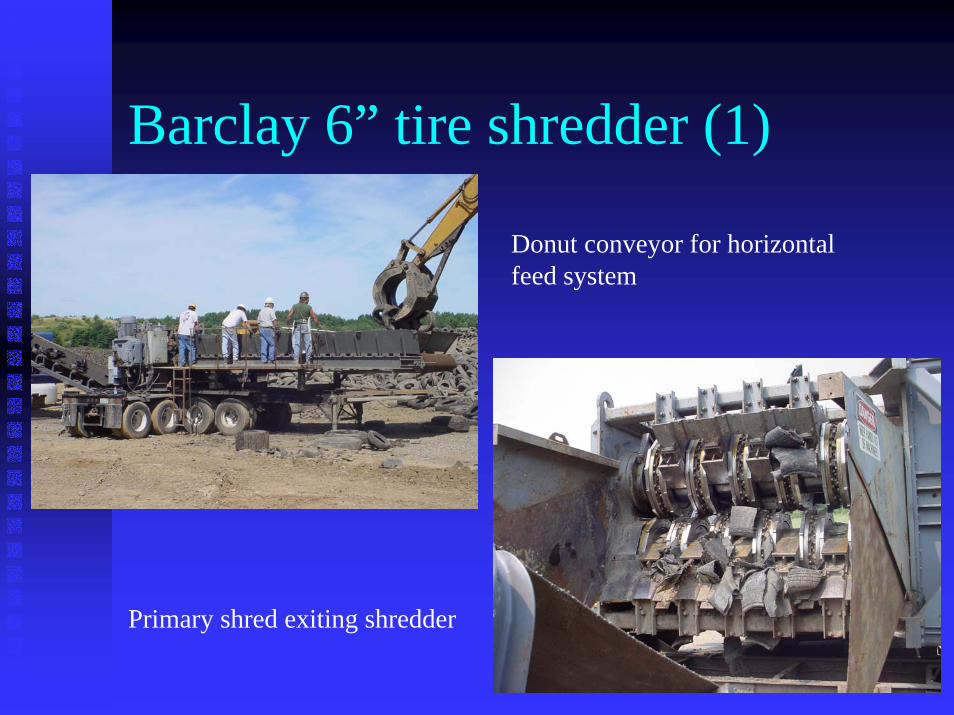
Barclay 6” tire shredder (1)
Donut conveyor for horizontalfeed system
Primary shred exiting shredder

Barclay 6” tire shredder (2)Track system for horizontal feed system
Water cooling of blades may be necessary when tires are dry

Tri-C 3.69” tire shredder
Tri-C has star-wheel feeders to prevent bridging. Teeth are notched and hooked.

Oversize Tire Shred Recycle

Flower wheel classifier (1)
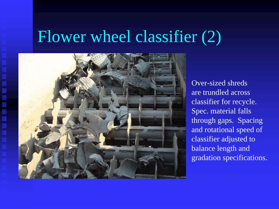
Flower wheel classifier (2)
Over-sized shreds are trundled acrossclassifier for recycle.Spec. material falls through gaps. Spacing and rotational speed ofclassifier adjusted to balance length andgradation specifications.

1.5’ Trommel ScreenTrommel screen removes free steel, soil, leaves and other fine debris

FaultyTire Shreds
Length, free, exposed steel

Approved Tire Shreds
Clean cuts most desirable outcome

PENNDOT Tire Shredding SiteTire Shred Stockpiles(300 x 50 x 15 ft, with 25 ft fire lanes)

Tarrtown Bridge SiteBridge Site Aerial Photograph
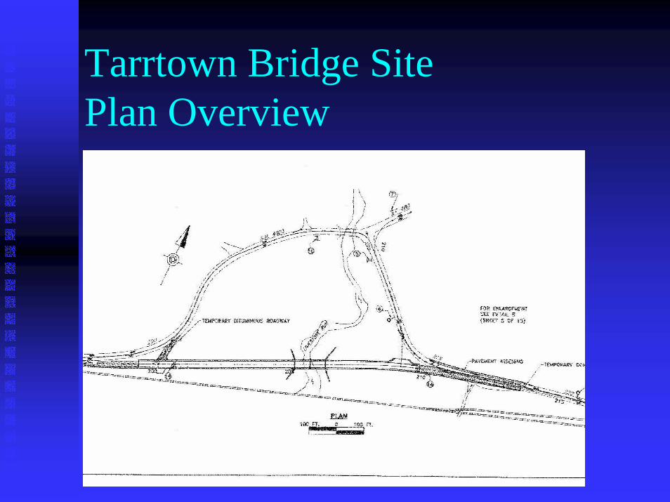
Tarrtown Bridge SitePlan Overview

Tarrtown Bridge SitePre-construction Conditions
Limestone Creek. Very soft soils—SPT weight of hammer

Tarrtown Bridge SiteCross Section
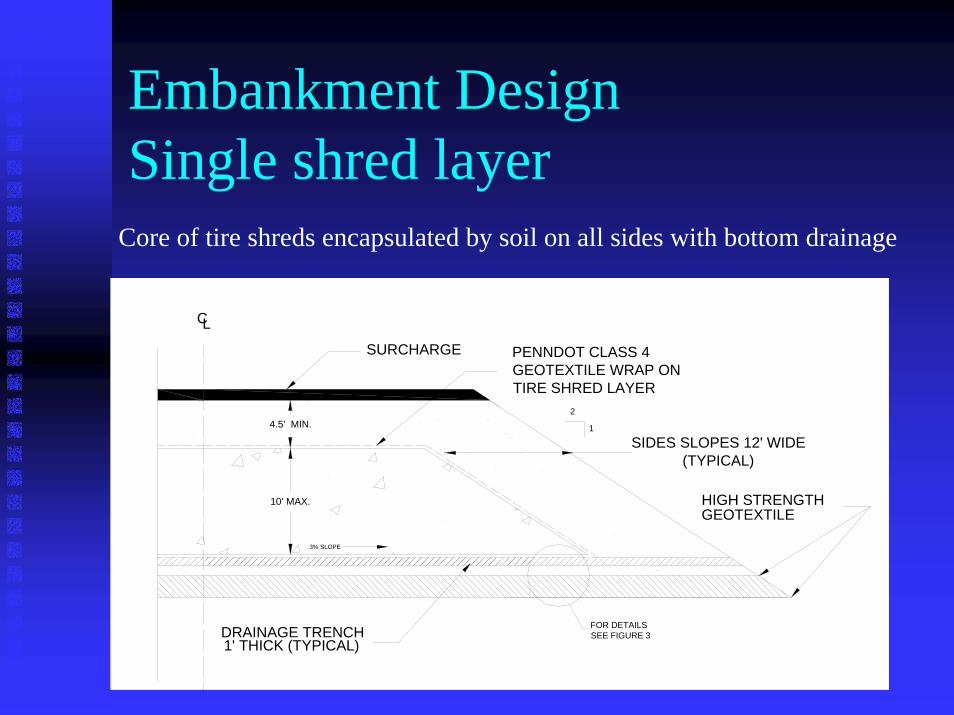
Embankment DesignSingle shred layer
10' MAX.
DRAINAGE TRENCH1' THICK (TYPICAL)
C
SIDES SLOPES 12' WIDE(TYPICAL)
3% SLOPE
4.5' MIN.
SURCHARGE
GEOTEXTILE
PENNDOT CLASS 4GEOTEXTILE WRAP ON TIRE SHRED LAYER
FOR DETAILSSEE FIGURE 3
2
1
L
HIGH STRENGTH
Core of tire shreds encapsulated by soil on all sides with bottom drainage

Embankment DesignDual shred layer
10' MAX.
DRAINAGE TRENCH1' THICK (TYPICAL)
C
SIDES SLOPES 12' WIDE(TYPICAL)
3% SLOPE
SURCHARGE
GEOTEXTILE
PENNDOT CLASS 4GEOTEXTILE WRAP ON TIRE SHRED LAYERS (TYPICAL)
10' MAX.
4.5' MIN.
3' MIN.
2
1
3% SLOPE
L
FOR DETAILSSEE FIGURE 3
HIGH STRENGTH
Same as single layer system, but with interlayer of soil

Embankment Instrumentation•Vertical Inclinometers with settlement magnets•Total Pressure Cells (TPCs) •Piezometers•Thermistors•Settlement Plates
Instrumentation plan relatively sophisticated to allow for potential rollout in a variety of configurations. Alarm system installed due to very poor foundations conditions even with using tire shreds

Instrumentation- Plan Overview
F
F F
F
F
F
F
F
F
STATION
204+25
(207+50)
STATION
204+00
(208+00)
STATION
204+50
(207+00)
STATION
204+60
(206+90)
EDGE OF
(TYPICAL)
ABUTMENT 1
INCLINOMETER LOCATION(TYPICAL)
DRAINAGE TRENCHSEE FIGURE 3
CABLETRENCH
AUTOMATED DATA LOGGER (ADL)SEE NOTE 2 AND FIGURE 3 TPC CABLE IN PVC
CONDUIT IN ABUTMENT
TOTAL PRESSURE CELLS (TPC's)
PIEZOMETERLOCATION(TYPICAL)
CONNECTOR TRENCH
9"
FILL
CONNECTOR TRENCH FROM ADL POLE TO CABLE TRENCH
(ABUTMENT 2)
ROW 1
ROW 2
ROW 3
ROW 4
ROW 5STATION
204+40
(207+10)
ROAD CENTERLINE
SETTLEMENT PLATE
STATION
204+10
W1 (W9)
W2(W10)
W3 (W11)
W4(W12)
W5 (W13)
W6I6 (I16)
W7I7 (I17)
W8I8 (I18)
I9 (I19)
I10 (I20)
I1 (I11)
I2 (I12)
I3 (I13)
I4 (I14)
I5 (I15)
(TYPICAL)

Instrumentation- Cross-Section
10' MAX.
DRAINAGE TRENCH1' THICK (TYPICAL)
C
3% SLOPE
4.5' MIN.
1/6 W
1/3 H
2/3 H
1/3 W
DATUM MAGNETS
INCLINOMETER
2
1
L
BEDROCK
PIEZOMETER 10' OFFSET FROM INCLINOMETER
1/6 W1/3 W1/3 H
EXISTING SOIL

Inclinometers & Base Magnets (Grouted in Bedrock)
Double magnets grouted in bedrock on inclinometer to establish base fixity (zero reference frame).

Spring Leaf (Spider) Magnets
Retracted arms released once positioned at desired elevation in foundation.
Arms lock magnet intofoundation soil, allowing magnet to slide down inclinometer as foundation settles.

Plate Magnets
2 x 2 ft. plate magnets installed at base of embankment and soil-tire shred interfaces
Plate magnets used to differentiate embankment compression (tire shred layers) from consolidation of foundation.

Piezometers & ThermistorsWater Pressure (psi or kPa)
Temperature (°C or °F)
Cable lengths custom made

Instrumentation- Abutments
4.5' SOIL FILL (MIN.)
TIRE SHRED LAYER
3' SOIL FILL
TIRE SHRED LAYER
2' SOIL FILL
WORKING MAT
4.5' SOIL FILL (MIN.)
TIRE SHRED LAYER
WORKING MAT
2' SOIL FILL
POSITIONTPCs AT
MIDPOINT OF EACH LAYER
POSITION TPCs3.33 FEET
ON CENTER
ELEVATION 792 FEET (ABOVE SEA LEVEL)
ABUTMENT 1 (WEST)
ABUTMENT 2 (EAST)
POSITION TPCs AT
MIDPOINT OF EACH LAYER(ELEVATION
791)
(10 FEET) (10 FEET)
TYPICAL INSTRUMENTATION FOR BRIDGE ABUTMENTS
P1
P2
P3
P4
P5
P6
P7
P8
P9
P10

Total Pressure Cells (introduction)
Measures soil pressure (psi or kPa) against abutments
Pa (lbs/ft) = 0.5 Ka γ H2
Ka (-) = tan2 (45+φ/2)
Tires predicted to be 30% less!
Measures temperature of fill at abutments

Total Pressure Cells (installation)
Embedded and calibrated in 1 x 1 ft. concrete pads
Flush-mounted on abutmentformwork facing fill.

Total Pressure Cells (protective conduit)
Main conduit trunk protects TPC sensors & routes cables to data logger.
Conduit exiting base of wing wall below final grade.

Total Pressure Cells (installed)Completed abutment& wingwalls
Exposed TPC awaitingfill placement.
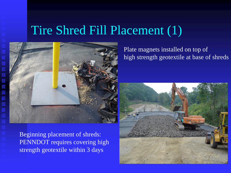
Tire Shred Fill Placement (1)Plate magnets installed on top of high strength geotextile at base of shreds
Beginning placement of shreds:PENNDOT requires covering high strength geotextile within 3 days

Tire Shred Fill Placement (2)Tire shreds unloaded & spread across geotextilewith excavator.
Method Compaction Specification:6 passes with >20,000 lb roller.
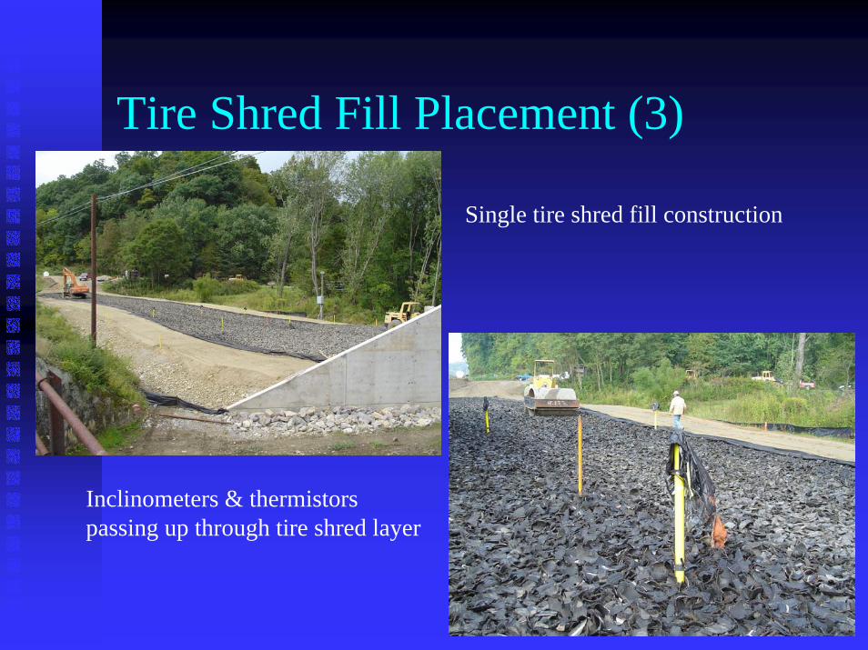
Tire Shred Fill Placement (3)
Single tire shred fill construction
Inclinometers & thermistorspassing up through tire shred layer

Tire Shred Fill Placement (4)
TPC in abutment being buried
Spider magnet installed in tire shred fill
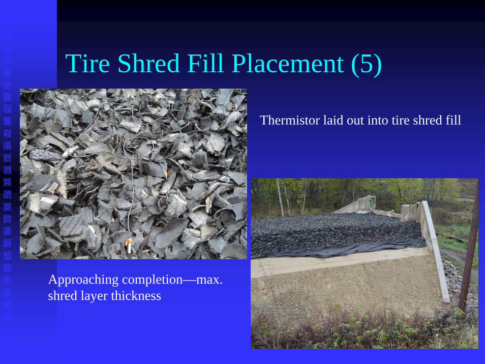
Tire Shred Fill Placement (5)
Thermistor laid out into tire shred fill
Approaching completion—max.shred layer thickness

Tire Shred Fill Placement (6)Inspection Issues: localized oil contamination (drippings) from excavator—impacted shreds removed
Inspection shows excessive mud being tracked into tire shred fill

For More InformationJim LellockPENNDOT Engineering District 10-0Bridge Unit2550 Oakland Ave.Indiana, PA 15071(724) 357-2441 tel(724) 357-1905 [email protected]