Presented by H.Schmickler - cas.web.cern.ch · PDF fileIEC 61204-3 ( replaced IEC-60478-3)...
57
Usage of DSP and in large scale power converter installations (LHC)* Presented by H.Schmickler Seminar prepared for the CAS on Digital Signal Processing Sigtuna (Sweden), June 2007 A CERN power converter is everybody else’s power supply
-
Upload
nguyentuyen -
Category
Documents
-
view
221 -
download
11
Transcript of Presented by H.Schmickler - cas.web.cern.ch · PDF fileIEC 61204-3 ( replaced IEC-60478-3)...

Usage of DSP and in large scale power converter installations (LHC)*
Presented by H.Schmickler
Seminar prepared for the CAS on Digital Signal Processing
Sigtuna (Sweden), June 2007
A CERN power converter is everybody else’s power supply

Contents
The main features of the LHCOne of the problems of the LHC:Persistent current decays and « Snapback » of the multi-pole components of the magnetic fieldThe specifications of the power convertersThe solution- hardware- software, the control algorithm

Contents
The main features of the LHCOne of the problems of the LHC:Persistent current decays and « Snapback » of the multi-pole components of the magnetic fieldThe specifications of the power convertersThe solution- hardware- software, the control algorithm

Key features of the LHC
• Protons and Ions• 450 GeV to 7 TeV: SPS is already there • High luminosity:
– Many bunches: 2808 bunches per beam– High beam currents – Small beam size at the interaction points
• Two rings:– Got to keep the beam apart– 2 in 1 dipole design
• LEP tunnel: might as well use that → B ≈ 8.4 T• High field: Superconducting magnets for the most part with dipoles
and lattice quadrupoles working at 1.9 K – superfluid helium (30 kTons cold mass; 90 Tons of Helium)
• Two high luminosity experiments• Two more specialised experiments (Ions and b physics) – lower
luminosity
We want to produce high luminosity at high energy so we can discover the Higgs, supersymmetry and other exciting stuff.


Atlas

CMS

Alice

LHCb

7 TeV beam in the LEP tunnel (100 GeV)
ep
emvB ==ρ
]/[][2998.01
cGeVpTB
peB ×
==ρ
3101.512322 −×===π
ρθ l
[ ] Tl
cGeVpTB 33.82998.03.14
7000101.52998.0
]/[ 3
=×
××=
××
=−θ
1232 magnets to get us round in a circle
Needs superconducting magnets

LHC - dipole
B +J -J

LHC - quadrupole
Two intersecting ellipses, rotated by 90°, generate a perfect quadrupole fields

Name Quantity Purpose
MSCB 376 Combined chromaticity/ closed orbit correctors
MCS 2464 Dipole spool sextupole for persistent currents at injection
MCDO 1232 Dipole spool octupole/decapole for persistent currents
MO 336 Landau octupole for instability control
MQT 256 Trim quad for lattice correction
MCB 266 Orbit correction dipoles
MQM 100 Dispersion suppressor quadrupoles
MQY 20 Enlarged aperture quadrupoles
Corrector Circuits
Contents
The main features of the LHCOne of the problems of the LHC:Persistent current decays and « Snapback » of the multi-pole components of the magnetic fieldThe specifications of the power convertersThe solution- hardware- software, the control algorithm

ΔB
+Jc-Jc MDCStrand
Filament
Cable
In order to generate 8,33 T in the dipoles, about 11.000 Amperes have to flow in the superconducting cable

Eddy Currents
⊗ dB/dt
resistive contact Rcat cross-over point
induced eddy currents in the loop I ∝ -dB/dt and I ∝ 1/Rc
superconductingpath in the strands
⊗ dB/dt
resistive contact Rcat cross-over point
induced eddy currents in the loop I ∝ -dB/dt and I ∝ 1/Rc
superconductingpath in the strands
Courtesy of L. Bottura - CERN

Snapback
0
1
2
3
4
5
0 500 1000 1500
time from beginning of injection (s)
b3 (u
nits
@ 1
7 m
m)
500
700
900
1100
1300
1500
dipo
le c
urre
nt (A
)
snap-back
decay

Effect of Snap-back in LHCAn uncorrected snap-back (of the expected magnitude) will cause in LHC:
Δb1(MB)=2.6 → ΔQ = 0.026 vs. 0.003
Δb2(MQ)=1.7 → ΔQ = 5.4 10–3 Δb2 =0.009 vs. 0.003
Δb3(MB)=3.3 → Δξ = 52 Δb3 = 172 vs. 1
Value vs. tolerance
(source: O. Bruening, CERN)

• Decay of persistent currents & snap-back – large variations in multipole errors– unacceptable effect on key beam parameters
• Strong dependence on magnetic history• Strategy:
– Reproducibility • well defined operational cycle• full recycle in case of problems• feed-forward of experience
– Multipole factory:• magnetic measurements• models of multipole behaviour which can take
into account powering history • on-line magnetic measurements
– Feedback on beam based measurements
Dynamic Effects problem

Baseline cycle
0
2000
4000
6000
8000
10000
12000
-3000 -2500 -2000 -1500 -1000 -500 0 500 1000 1500 2000
Time [s]
MB
cur
rent
0
1
2
3
4
5
6
7
8
9
B [T
]
Preinjection plateau
Ramp down
Start ramp
Injection
Beam dump
Physics PreparePhysics
Ramp down ≈ 18 MinsPre-Injection Plateau 15 Mins
Injection ≈ 15 MinsRamp ≈ 28 Mins
Squeeze < 5 MinsPrepare Physics ≈ 10 Mins
Physics 10 - 20 Hrs
In the normal operations the LHC will perform a standard
cycle which will be more-or-less set in stone.

Contents
The main features of the LHCOne of the problems of the LHC:Persistent current decays and « Snapback » of the multi-pole components of the magnetic fieldThe specifications of the power convertersThe solution- hardware- software, the control algorithm
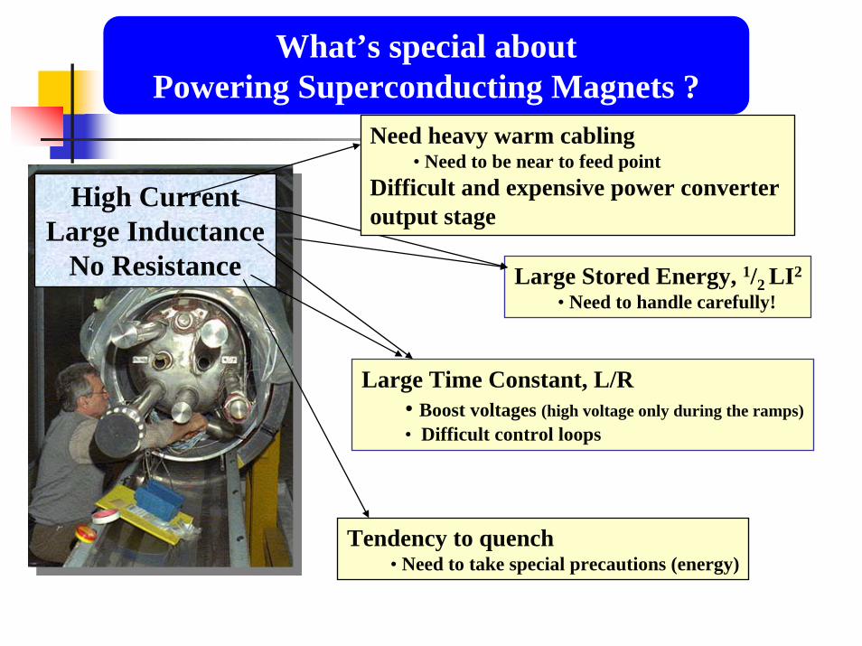
High Current Large Inductance
No Resistance
Large Time Constant, L/R• Boost voltages (high voltage only during the ramps)• Difficult control loops
Tendency to quench• Need to take special precautions (energy)
What’s special about Powering Superconducting Magnets ?
Large Stored Energy, 1/2 LI2
• Need to handle carefully!
Need heavy warm cabling• Need to be near to feed point
Difficult and expensive power converter output stage

LHC : 1232 SC Main Dipole magnetsLHC : 1232 SC Main Dipole magnets
One circuit or several circuits ?
Magnet inductance : L = 108 mH
Ltotal=1232 * 0.108 = 133 HRamp: LdI/dt = 1330V
Discharge (quench; 120 A/s): ≅ 16kV
Nominal current 11.8 kAStored Energy = 9.3 GJ
Ultimate current = 13kAStored Energy = 11.3 GJ

Sector 1
5
DC Power feed
3
Oct
ant
DC Power
2
4 6
8
7LHC27 km Circumference
Powering Sector:
154 dipole magnetsabout 50 quadrupolestotal length of 2.9 km
Powering Subsectors:
• long arc cryostats• triplet cryostats• cryostats in matching section
Powering Subsectors allow for progressive Hardware Commissioning - 2 years before beam
LHC Powering in 8 Sectors
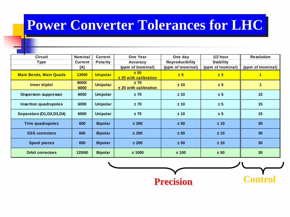
Power Converter Tolerances for LHCPower Converter Tolerances for LHC
Precision Control
Inner triplet 8000/ 6000
Unipolar ± 70 ± 20 with calibration
± 10 ± 5 1
Dispersion suppressor 6000 Unipolar ± 70 ± 10 ± 5 15
Insertion quadrupoles 6000 Unipolar ± 70 ± 10 ± 5 15
Separators (D1,D2,D3,D4) 6000 Unipolar ± 70 ± 10 ± 5 15
Trim quadrupoles 600 Bipolar ± 200 ± 50 ± 10 30
SSS correctors 600 Bipolar ± 200 ± 50 ± 10 30
Spool pieces 600 Bipolar ± 200 ± 50 ± 10 30
Orbit correctors 120/60 Bipolar ± 1000 ± 100 ± 50 30
Circuit Nominal Current One Year One day 1/2 hour ResolutionType Current Polarity Accuracy Reproducibility Stability
(A) (ppm of Inominal) (ppm of Inominal) (ppm of Inominal) (ppm of Inominal)
Main Bends, Main Quads 13000 Unipolar ± 50 ± 20 with calibration
± 5 ± 3 1

LHC Power Converters
Number of Converters: > 1700Total Current :1860 kA
Steady State Input : 63 MWPeak Input : 85 MVW
Underground volume ≅ 1700 m3Surface volume ≅ 300 m3
Number of Converters: > 1700Total Current :1860 kA
Steady State Input : 63 MWPeak Input : 85 MVW
Underground volume ≅ 1700 m3Surface volume ≅ 300 m3

Performance :-High current with high precision (accuracy, reproducibility,stability, resolution) and large dynamics-current range (for 1-quadrant converter: from 1% to 100%)- a lot of 4-quadrant converters (energy from magnets)- tracking : Need to track from sector to sector- voltage ripple and perturbation rejection
LHC Powering Challenges :LHC Powering Challenges :
Installation (LEP infrastructure) and Operation:- volume (a lot of converter shall be back-to-back)- weight (difficult access) => modular approach- Repairability and rapid exchange of different parts- radiation for [±60A,±8V] converters- losses extraction : high efficiency (>80%) , water cooling (90% of the losses)- High reliability (MTBF > 100’000 h)- EMC : very close to the others equipment ; system approach

Contents
The main features of the LHCOne of the problems of the LHC:Persistent current decays and « Snapback » of the multi-pole components of the magnetic fieldThe specifications of the power convertersThe solution- hardware- software, the control algorithm

WorldFIP 2.5Mb/s
Overview – A Power Converter
Terminalor PC
RS2329.6Kbaud
FunctionGenerator/Controller
VoltageSource
CircuitCurrentMeasurement

Digital domain
Overview – Analogue Regulation
Traditional Method used for PS, SPS and LEP
Iref Vout
Iout
VoltageSource
Traditional analogue regulation suffers from serious limitations:
•Inaccurate for very slow circuits (superconducting magnets)
•Simple analogue control suffers from dynamic errors
•Accuracy depends upon current transducer and DAC
VrefF(s)DAC

Vref Vout
Iout
VoltageSource
Digital domain
New method for LHC
Overview – Digital Regulation
Iref
Digital regulation has been chosen for LHC because:
•It accommodates all circuit time constants (0.1 – 20000 s)
•Advanced digital control algorithm can eliminate dynamic errors
•Accuracy depends “only” upon current transducer and ADC
T(z-1) 1/S(z-1) DAC
R(z-1) ADC

Controller Hardware Overview
Twin Processor16 bit micro-controller (MC68HC16Z1 @ 16 MHz)32 bit floating point DSP (TMS320C32 @ 32 MHz)
Radiation toleranceError detection and correction on all SRAMMultiple watchdogs including power cycling
WorldFIP 2.5Mb/s
RS2329.6Kbaud
FunctionGenerator/Controller
VoltageSource

DSP Applications: LHC FGC
LHC Function Generator/Controller project:
•2000 units, mostly for power converter control.
•Motorola MC68HC16Z1 chosen a main processor.
•Significant floating point maths requirement.
•TI TMS320C32 DSP chosen as a co-processor.
TMS320C32MC68HC16Z1FGC designed and built by CERN; series production of~2000 pieces

~1800
Overview – System Architecture
GatewayGatewayGatewayGatewayUp to 30 Digital Controllers
Per WorldFIP fieldbus~100
App
App App App
App
LHCControls
LAN

System Software Overview
GatewayGatewayGatewayGateway
App
App App App
App
Application SoftwareLanguage: JavaGUI: Swing
Gateway SoftwareRTOS: LynxOSLanguages: C, C++Tools: GNUCommunications
Middleware: CORBA Real-time: UDP
Controller SoftwareMicro-controller
RTOS: NanOS (1.2KB)Languages: C, AssemblerTools: Metrowerks
DSPRTOS: NoneLanguages: C, AssemblerTools: Texas Instruments
Offline SoftwareScripting: PERLDefinition files: XMLDatabase: ORACLEDoc: HTML

Now a closer look ……. at the system components

CurrentTransducer
DCCT
FunctionGenerator
Current loop
Vref
Mag
netsPower Part
(Voltage Source)
AC Mains Supply
Iref
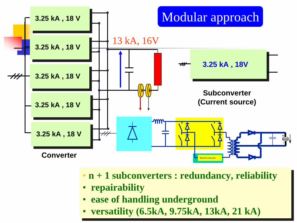
Subconverter(Current source)
3.25 kA , 18V
Reactive network
+
-
• n + 1 subconverters : redundancy, reliability• repairability• ease of handling underground• versatility (6.5kA, 9.75kA, 13kA, 21 kA)
• n + 1 subconverters : redundancy, reliability• repairability• ease of handling underground• versatility (6.5kA, 9.75kA, 13kA, 21 kA)
13 kA, 16V
Converter
3.25 kA , 18 V
3.25 kA , 18 V
3.25 kA , 18 V
3.25 kA , 18 V
3.25 kA , 18 V
Modular approach

Iout(sub-converter) 200A/V
Vref
Vout (Converter)
Converter Operation during a subconverter failure
ΔI < 10 ppm of Imax on magnet(s) with L > 0.1 H
Example: [6kA,8V] converter : (3+1) x [2kA,8V] subconverters
One subconverter failure
2 kA , 8 V
2 kA , 8 V
2 kA , 8 V
2 kA , 8 V
6 kA, 8V

Emission :IEC 61204-3 ( replaced IEC-60478-3) (CISPR 11 ; EN 55011)
Emission :IEC 61204-3 ( replaced IEC-60478-3) (CISPR 11 ; EN 55011)
EMC : ELECTROMAGNETIC COMPATIBILITY
IEC 61000-4-4
Norms for the power converters :
Immunity : IEC 61000 - 4 : Burst 61000 - 4 - 4 Surge 61000- 4 - 5
Immunity : IEC 61000 - 4 : Burst 61000 - 4 - 4 Surge 61000- 4 - 5
COMPATIBILITY : Emission - Immunity IEC 61204 -3

EMC conducted noise: Common Mode Emissions (9 kHz - 30 MHz) DC- Side
[±600A, ±40V]at 600A, 39V
[6kA, 8V]at 6kA, 8V

CurrentTransducer
DCCT
FunctionGenerator
Current loop
Vref
Mag
netsPower Part
(Voltage Source)
AC Mains Supply
Power Interlock Controller
Cooling System
WorldFIP(Iref)

- Highest performance - state of the art- Separate Head and electronics chassis 19” rack mounting.- Fitted with Calibration Windings- Temperature-controlled environment in the Accelerator.- Full testing and calibration at CERN on a 20kA Test Bed.
- Highest performance - state of the art- Separate Head and electronics chassis 19” rack mounting.- Fitted with Calibration Windings- Temperature-controlled environment in the Accelerator.- Full testing and calibration at CERN on a 20kA Test Bed.
DCCTs (13kA)

600A
120A
DCCTs
4kA to 8kA

CurrentTransducer
DCCT
FunctionGenerator
Current loop
Vref
Mag
netsPower Part
(Voltage Source)
AC Mains Supply
Power Interlock Controller
Cooling System
WorldFIP(Iref)

FrequencyDivider
T 1/Syref(k)
k.Ts
ADC
Power Party(t)
DAC
Antialiasing
filter÷ k Digital
FilterR
Ts
Over sampling
Digital controller
Tracking RegulationTracking and Regulation with
independent objectives
Digital current loop : RST algorithm

( )211 −− z
RST CONTROLLER DESIGN
Tracking:To get a good tracking of the reference (no lagging error, no overshoot), the transfer function that the controller must achieve between the reference iref* and the output im* is:
1*
* −= zirefim
Regulation:According to the LHC cycle, the bandwidth for the closed-loop system is chosen fB
CL
∈[0.1Hz,1Hz]. The regulation is defined by the pole placement with a natural frequency wcl∈[0.628rad/s, 6.28rad/s] and with a damping factor greater than 1. To ensure a zero steady-state error when the reference is constant, the transfer function 1/S(z-1) must contain two integrators .
TMS320C32MC68HC16Z1

iref* vref*T(z-1) 1/S(z-1)
R(z-1) im*
+-
z-1B(z-1)A(z-1)
Process
p*
+
+ 1
1
.....
**
−
−
+=
zBRSATBz
irefim
1....
**
−+=
zBRSASA
pim
Tracking:
Regulation:
R.S.T

SummarySummary
T 1/Syref(k)
k.Ts
ADC
Systemy(t)
DAC
Antialiasing
filter÷ k
FrequencyDivider
DigitalFilterR
Ts
Oversampling
System model ?fCL
B (tr) , Q (M) ?
Ts ?
Based on fOLB and power of the actuator : choice of the
closed-loop performance [fCLB (tr) and Q (M) ]
Robustness ; fCLB / fOL
B (Internal saturation : controlability)
fs (sampling frequency) : choice based on the fCLB
fs = 1/Ts = (6 to 25) * fCLB
Discrete model H(z-1) at Ts
Digital controller

760,00
760,40
760,80
761,20
761,60
0 2 4 6 8 10 12 14 16 18 20Seconds
Amps
ImeasIref
LHC dipole circuit ramp (0-20s)
50 ppm
Parabolic acceleration = 0.009 A/s2

LHC dipole circuit ramp (0-4s)
759,98
760,00
760,02
760,04
760,06
0 1 2 3 4Seconds
Amps
ImeasIref
2 ppm

11790
11800
11810
11820
11830
11840
11850
1615 1620 1625 1630 1635Seconds
Amps
ImeasIref
LHC dipole circuit ramp (last 15s)
2000 ppm
Parabolic deceleration = 0.5 A/s2

11799,2
11799,6
11800,0
11800,4
1615,5 1615,6 1615,7Seconds
Amps
ImeasIref
LHC dipole circuit ramp (200ms)
50 ppm

11849,6
11849,7
11849,8
1628,7 1629,2 1629,7 1630,2Seconds
Amps
ImeasIref
LHC dipole circuit ramp (last 1s)
10 ppm

0,000
0,002
0,004
0,006
0,008
0,010
1615 1620 1625 1630 1635Seconds
AmpsRMS Error
Control Algorithm RMS Error
1 ppm

Quick Summary:
The LHC represents many technological challengesOne challenge is cost effective time synchronous control of 1700 power converters with very high precision…plus radiation resistanceThe challenge is met with a CERN built system based on floating point DSPs

Thanks to:
Freddy Bordry, Quentin King; Luca Bottura and Mike Lamont for their slides
To you for listening!

![[XLS]mams.rmit.edu.aumams.rmit.edu.au/urs1erc4d2nv1.xlsx · Web view0. 0. 0. 0. 0. 0. 0. 0. 0. 0. 0. 0. 0. 0. 0. 0. 0. 0. 0. 0. 0. 0. 0. 0. 0. 0. 0. 0. 0. 0. 0. 0. 0. 0. 0. 0. 0.](https://static.fdocuments.in/doc/165x107/5ab434027f8b9a0f058b8cff/xlsmamsrmitedu-view0-0-0-0-0-0-0-0-0-0-0-0-0-0-0-0-0-0-0.jpg)


![[XLS] · Web view0 0 7/31/2018 10/16/2017 0 0 39 40 41 42 43 0 2 0 0 0 0 2 0 0 0 0 2 0 0 0 0 1 0 0 0 0 2 0 0 0 0 1 0 0 0 0 2 0 0 0 0 2 0 0 0 0 2 0 0 0 0 2 0 0 0 0 2 0 0 0 0 2 0 0](https://static.fdocuments.in/doc/165x107/5afad2057f8b9a32348e4124/xls-view0-0-7312018-10162017-0-0-39-40-41-42-43-0-2-0-0-0-0-2-0-0-0-0-2-0.jpg)