Presented by G4: Erik Church Steve Nyquist Michael Grady Jennifer Miller H ighway A utomation S...
32
Presented by G4: Erik Church Steve Nyquist Michael Grady Jennifer Miller Highway Automation Simulation Kit Electronically Locating Lines
-
date post
21-Dec-2015 -
Category
Documents
-
view
216 -
download
0
Transcript of Presented by G4: Erik Church Steve Nyquist Michael Grady Jennifer Miller H ighway A utomation S...

Presented by G4:Erik Church
Steve NyquistMichael GradyJennifer Miller
Highway Automation Simulation Kit Electronically Locating Lines

Project Goals
• Design and build a car that will model an automated highway system
• The car must stay on a line and avoid collisions
• Stay within a $200 limit• Optimally, the car will go wicked fast• Generate a course geared towards
sophomores that will reproduce similar results
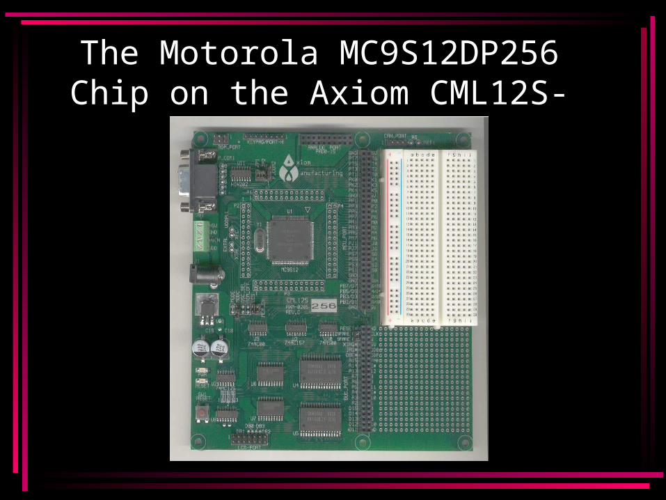
The Motorola MC9S12DP256 Chip on the Axiom CML12S-DP256
Board
Why use the CML12S-DP256?
• Two 8 Channel Analog-To-Digital Converters
• Eight Pulse Width Modulation Channels
• Numerous I/O Pins• Coded in Assembly Language
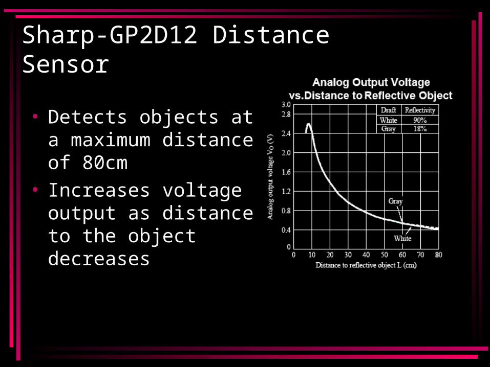
Sharp-GP2D12 Distance Sensor
• Detects objects at a maximum distance of 80cm
• Increases voltage output as distance to the object decreases
Tape Detection
• We used IR Emitters and Detectors to locate the tape
• Dark colors absorb IR while bright colors reflect it
• IR is emitted toward the floor• Tile floor reflects IR back to the detector
while the tape absorbs it– If an IR detector reads high IR it is over the
floor– If an IR detector reads low IR it is over the
tape
IR Emitter and Phototransistor
• IR Emitter: Jameco id#112150• IR Phototransistor: Jameco id#112168• Paired an emitter with each phototransistor• Benefits to using two components:
– Cheaper (8 emitters/ 8 detectors $3.04)• Disadvantages:
– Needed an addition breadboard
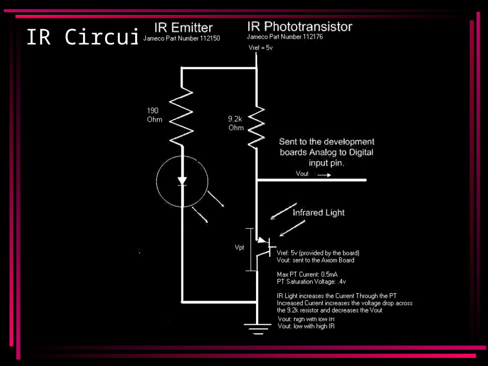
IR Circuit
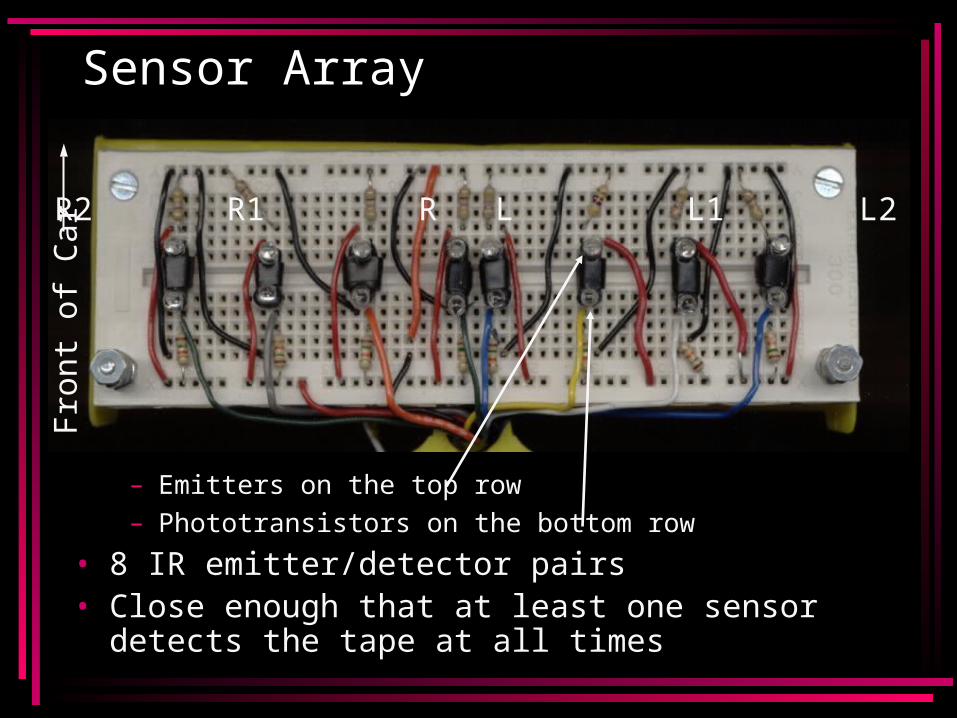
Sensor Array
– Emitters on the top row– Phototransistors on the bottom row
• 8 IR emitter/detector pairs• Close enough that at least one sensor detects
the tape at all times
R3 R2 R1 R L L1 L2 L3
Fro
nt o
f C
ar
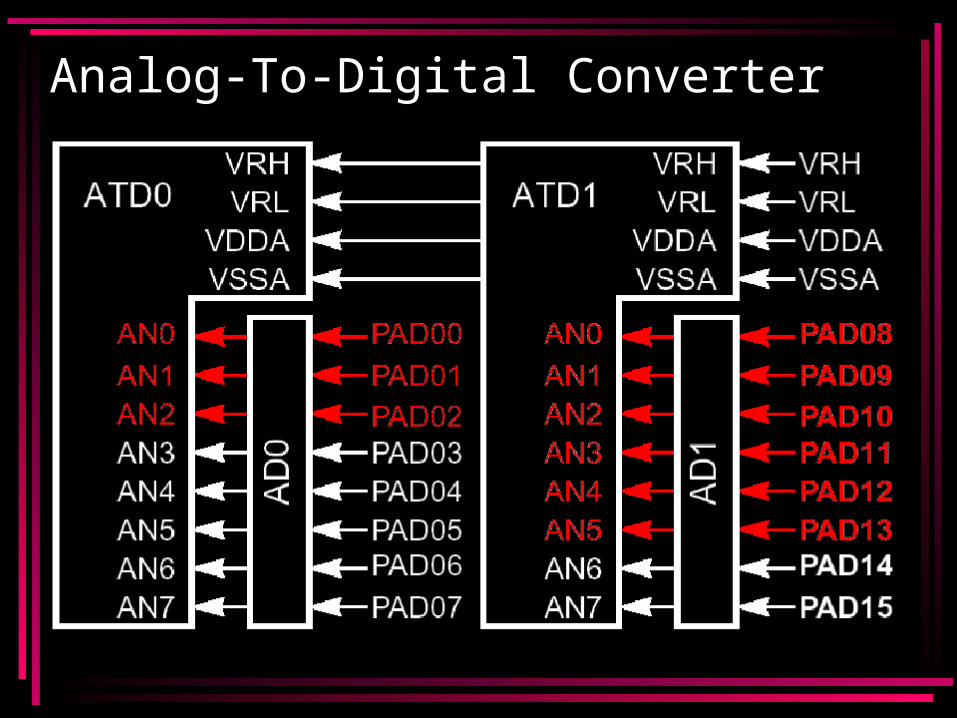
Analog-To-Digital Converter
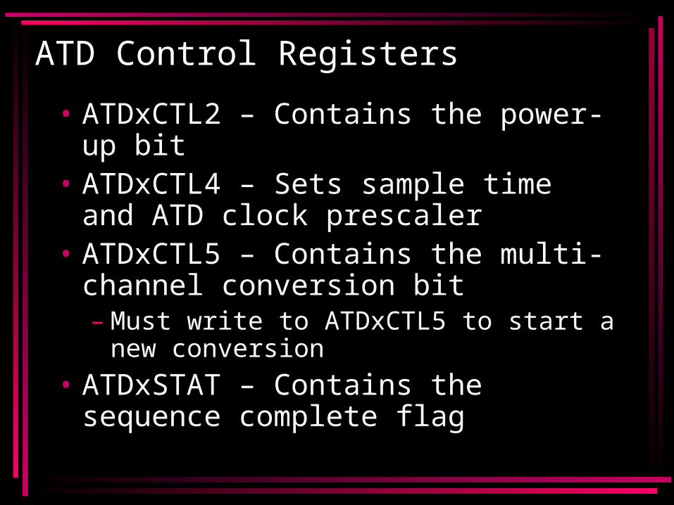
ATD Control Registers
• ATDxCTL2 – Contains the power-up bit
• ATDxCTL4 – Sets sample time and ATD clock prescaler
• ATDxCTL5 – Contains the multi-channel conversion bit– Must write to ATDxCTL5 to start a
new conversion• ATDxSTAT – Contains the sequence
complete flag
How to Read the ATD
• Once the sequence is complete, simply load ADRxy, where x is the ATD and y is the pin.
• Example: To read the last pin of ATD1, load ADR17.
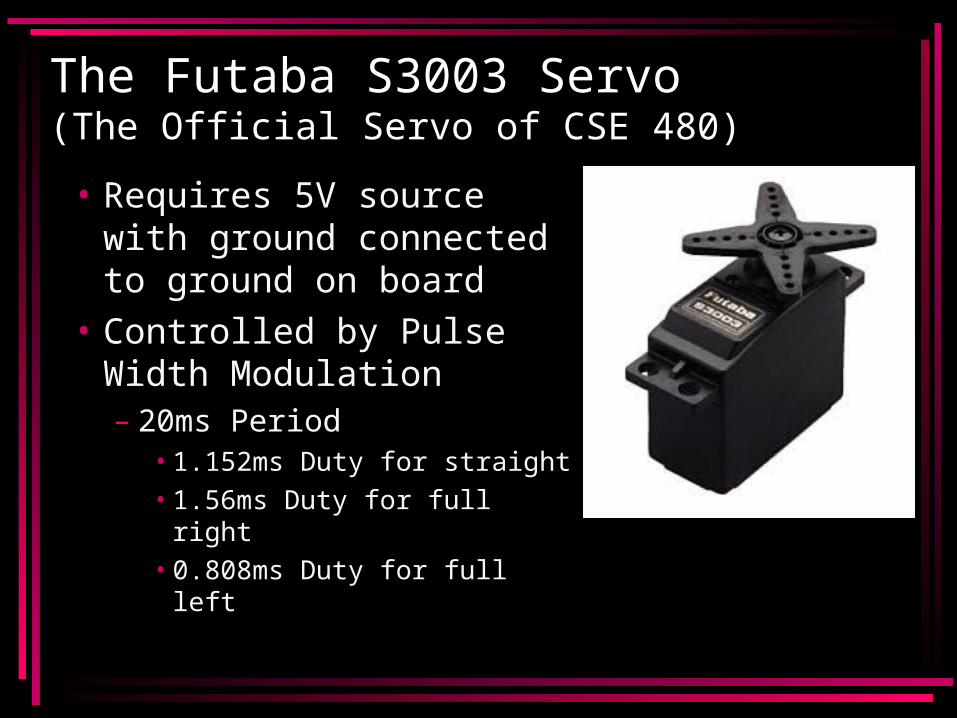
The Futaba S3003 Servo(The Official Servo of CSE 480)
• Requires 5V source with ground connected to ground on board
• Controlled by Pulse Width Modulation– 20ms Period
• 1.152ms Duty for straight• 1.56ms Duty for full right• 0.808ms Duty for full left
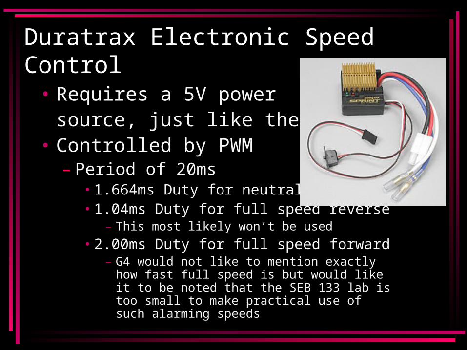
Duratrax Electronic Speed Control
• Requires a 5V power source, just like the servo
• Controlled by PWM– Period of 20ms
• 1.664ms Duty for neutral• 1.04ms Duty for full speed reverse
– This most likely won’t be used
• 2.00ms Duty for full speed forward– G4 would not like to mention exactly how
fast full speed is but would like it to be noted that the SEB 133 lab is too small to make practical use of such alarming speeds
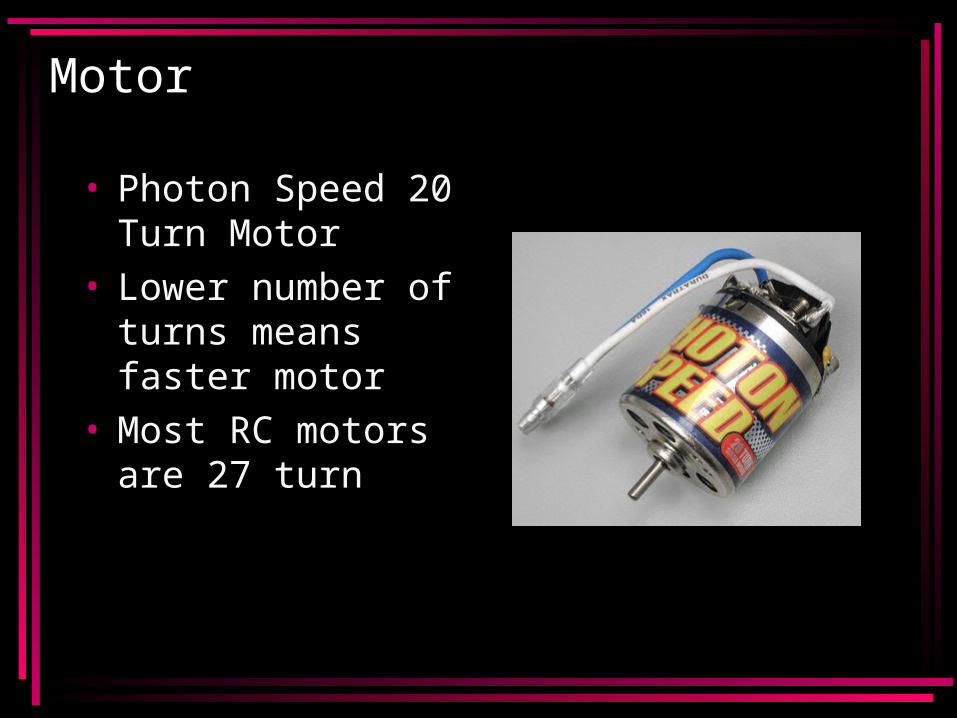
Motor
• Photon Speed 20 Turn Motor
• Lower number of turns means faster motor
• Most RC motors are 27 turn
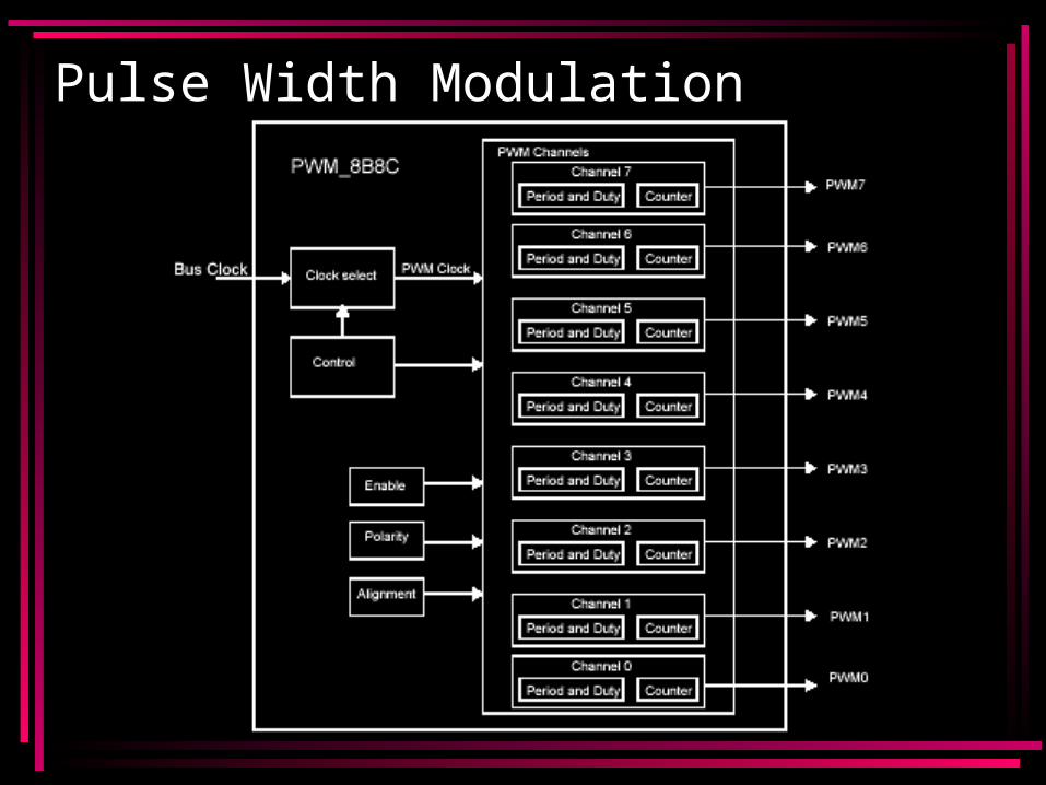
Pulse Width Modulation
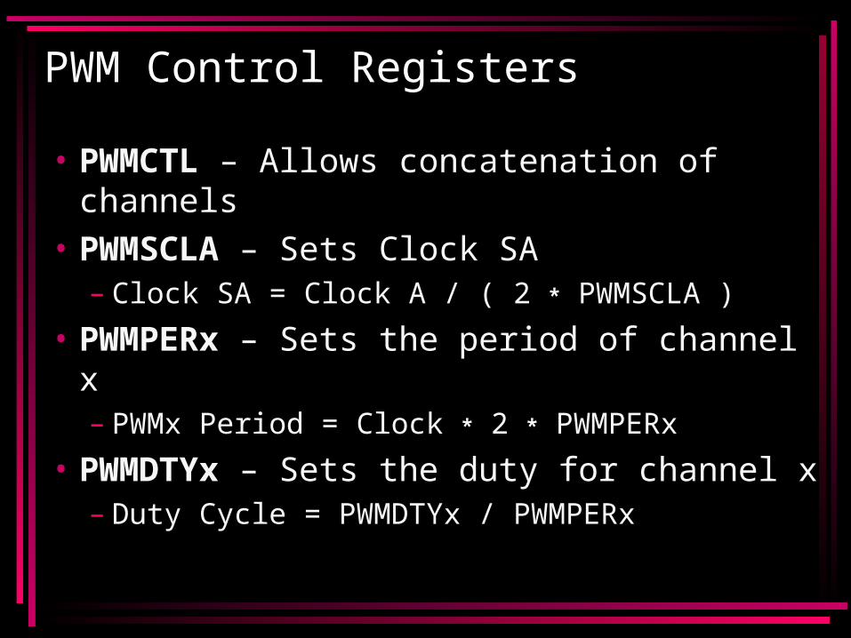
PWM Control Registers
• PWMCTL – Allows concatenation of channels
• PWMSCLA – Sets Clock SA– Clock SA = Clock A / ( 2 * PWMSCLA )
• PWMPERx – Sets the period of channel x– PWMx Period = Clock * 2 * PWMPERx
• PWMDTYx – Sets the duty for channel x– Duty Cycle = PWMDTYx / PWMPERx
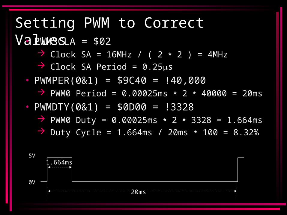
Setting PWM to Correct Values• PWMSCLA = $02
Clock SA = 16MHz / ( 2 * 2 ) = 4MHz Clock SA Period = 0.25s
• PWMPER(0&1) = $9C40 = !40,000 PWM0 Period = 0.00025ms * 2 * 40000 = 20ms
• PWMDTY(0&1) = $0D00 = !3328 PWM0 Duty = 0.00025ms * 2 * 3328 = 1.664ms Duty Cycle = 1.664ms / 20ms * 100 = 8.32%
5V
0V
20ms
1.664ms
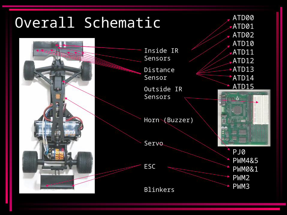
Overall Schematic
Inside IR Sensors
Distance Sensor
Outside IR Sensors
Horn (Buzzer)
Servo
ESC
Blinkers
ATD00 ATD01 ATD02 ATD10 ATD11 ATD12 ATD13 ATD14 ATD15
PJ0 PWM4&5 PWM0&1 PWM2 PWM3
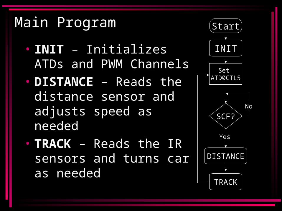
Main Program
• INIT – Initializes ATDs and PWM Channels
• DISTANCE – Reads the distance sensor and adjusts speed as needed
• TRACK – Reads the IR sensors and turns car as needed
Start
INIT
Set ATD0CTL5
SCF?
DISTANCE
TRACK
No
Yes
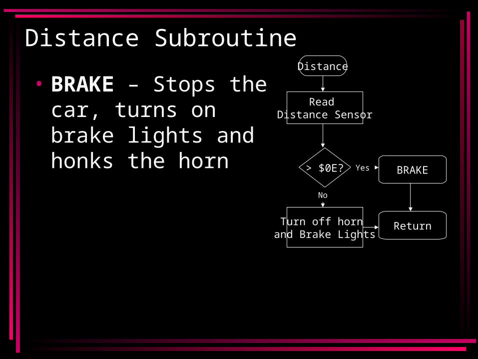
Distance Subroutine
• BRAKE – Stops the car, turns on brake lights and honks the horn
Distance
Read Distance Sensor
> $0E?
Turn off horn and Brake Lights
BRAKE
Return
Yes
No
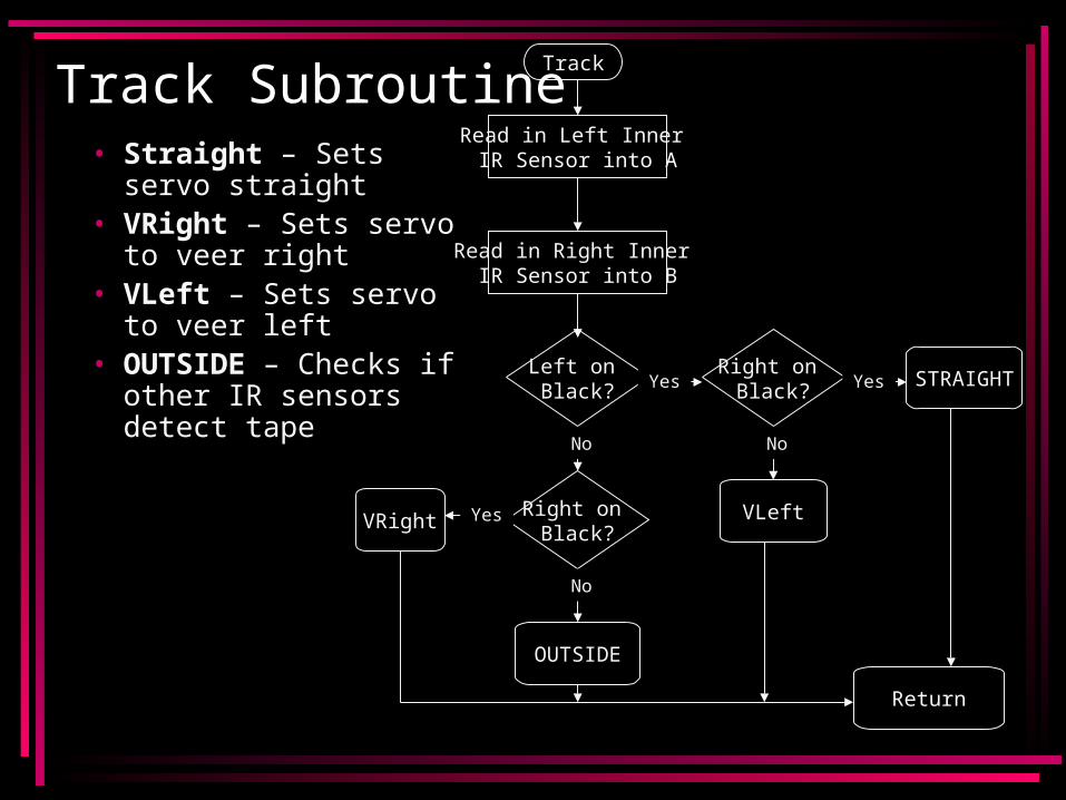
• Straight – Sets servo straight
• VRight – Sets servo to veer right
• VLeft – Sets servo to veer left
• OUTSIDE – Checks if other IR sensors detect tape
Track SubroutineTrack
Read in Left Inner IR Sensor into A
Read in Right Inner IR Sensor into B
Left on Black?
Right on Black?
Right on Black?
OUTSIDE
VRight VLeft
STRAIGHTYesYes
Yes
NoNo
No
Return
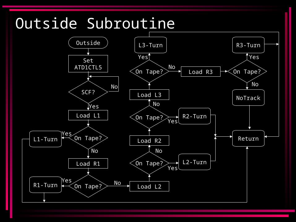
Outside SubroutineOutside
Set ATD1CTL5
SCF?
Load L1
On Tape?
Load R1
On Tape?
L1-Turn
Load L2
On Tape?
R1-Turn
R2-Turn
L2-Turn
Load R2
On Tape?
Load L3
On Tape?
R3-TurnL3-Turn
Load R3 On Tape?
NoTrack
Return
No
No
No
No
No
No
No
Yes
Yes
Yes
Yes
Yes
Yes Yes
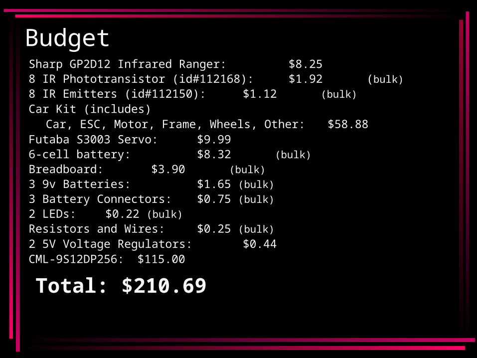
Budget Sharp GP2D12 Infrared Ranger: $$$8.258 IR Phototransistor (id#112168): 0$$1.92 (bulk)
8 IR Emitters (id#112150): 0$$1.12 (bulk)
Car Kit (includes)Car, ESC, Motor, Frame, Wheels, Other: $$58.88
Futaba S3003 Servo: $$$9.996-cell battery: $$$8.32 (bulk)
Breadboard: $$$3.90 (bulk)
3 9v Batteries: $$$1.65 (bulk)
3 Battery Connectors: $$$0.75 (bulk)
2 LEDs: $$$0.22 (bulk)
Resistors and Wires: $$$0.25 (bulk)
2 5V Voltage Regulators: $$$0.44 CML-9S12DP256: $115.00
Total: $210.69
Things We Could Have Changed
• Use Rechargeable Batteries• Utilize the LCD and Keypad that
came with the DP256 board• Use Better Distance Sensor/Better
Braking System• Use Better Horn
Ideal Car For Sophomore Design
• OOPIC board: Sophomores will already know VB from CSE141
• Create their own frame on Campus: More educational than ordering a kit
• Select motor based on requirements of car
• H-Bridge instead of ESC: Cheaper• Separate IR emitter/detector

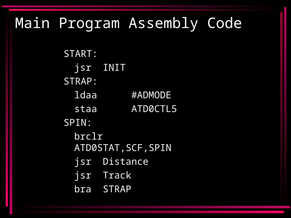
Main Program Assembly Code
START:
jsr INIT
STRAP:
ldaa #ADMODE
staa ATD0CTL5
SPIN:
brclr ATD0STAT,SCF,SPIN
jsr Distance
jsr Track
bra STRAP
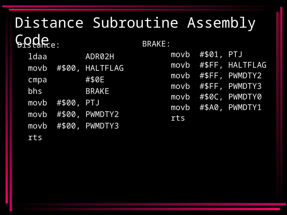
Distance Subroutine Assembly CodeDistance:
ldaa ADR02H
movb #$00, HALTFLAG
cmpa #$0E
bhs BRAKE
movb #$00, PTJ
movb #$00, PWMDTY2
movb #$00, PWMDTY3
rts
BRAKE:movb #$01, PTJmovb #$FF, HALTFLAGmovb #$FF, PWMDTY2movb #$FF, PWMDTY3movb #$0C, PWMDTY0movb #$A0, PWMDTY1rts
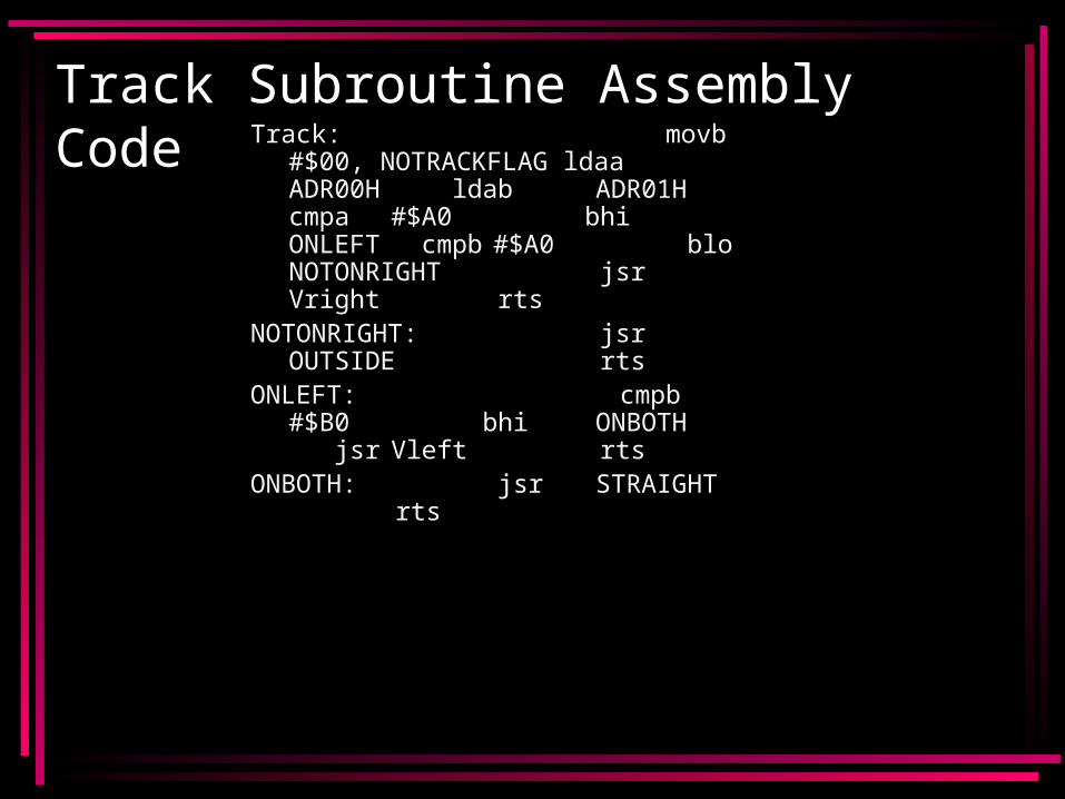
Track Subroutine Assembly CodeTrack:
movb #$00, NOTRACKFLAG ldaa ADR00H ldab
ADR01H cmpa#$A0 bhi
ONLEFT cmpb #$A0 blo NOTONRIGHT jsr Vright
rtsNOTONRIGHT:
jsr OUTSIDE rts
ONLEFT: cmpb #$B0
bhiONBOTH jsrVleft rts
ONBOTH: jsr STRAIGHT rts
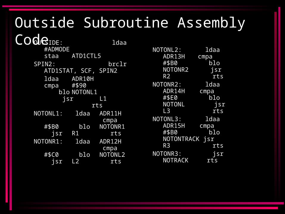
Outside Subroutine Assembly CodeOUTSIDE:
ldaa #ADMODE staaATD1CTL5
SPIN2: brclrATD1STAT, SCF, SPIN2ldaa ADR10H cmpa #$90
blo NOTONL1 jsr L1
rts
NOTONL1: ldaaADR11H cmpa #$B0 blo NOTONR1 jsrR1 rts
NOTONR1: ldaaADR12H cmpa #$C0 blo NOTONL2 jsrL2 rts
NOTONL2: ldaaADR13H
cmpa #$B0 blo NOTONR2 jsr R2 rts
NOTONR2: ldaaADR14H
cmpa #$E0 blo NOTONL jsr L3 rts
NOTONL3: ldaaADR15H
cmpa #$B0 bloNOTONTRACK jsrR3 rts
NOTONR3: jsrNOTRACK
rts
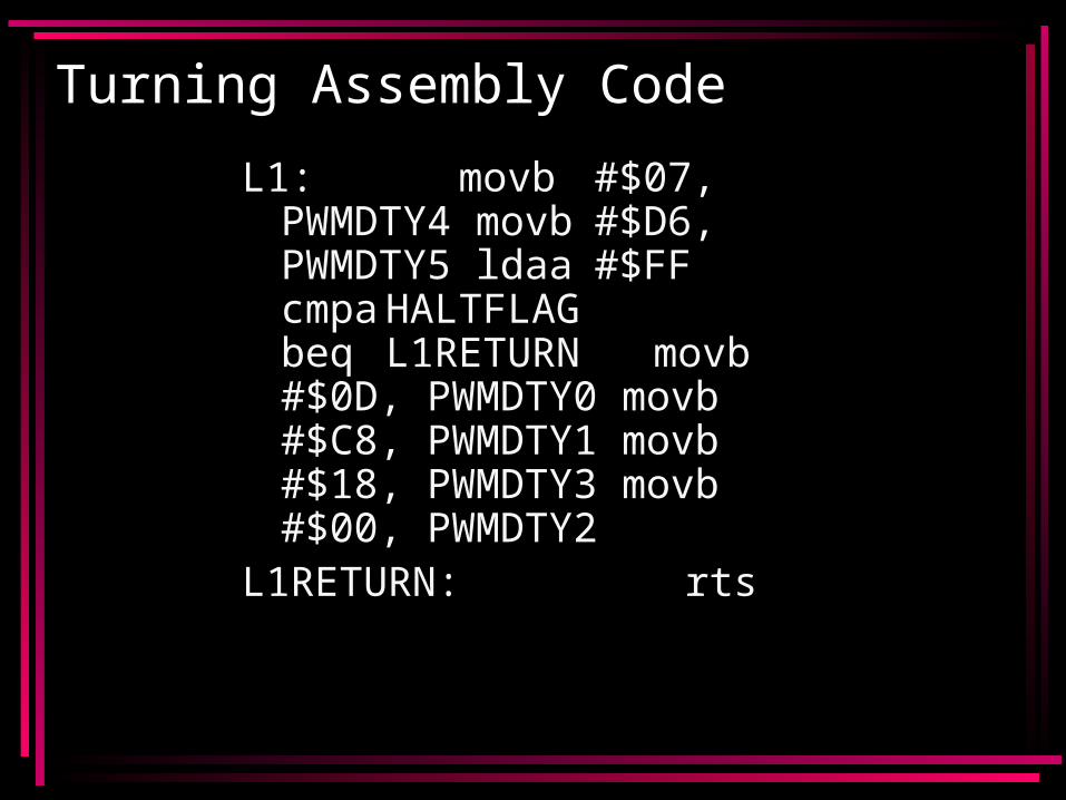
Turning Assembly Code
L1: movb#$07, PWMDTY4 movb#$D6, PWMDTY5 ldaa#$FF cmpaHALTFLAG beq L1RETURN movb#$0D, PWMDTY0 movb#$C8, PWMDTY1 movb#$18, PWMDTY3 movb#$00, PWMDTY2
L1RETURN: rts