Presented at the 92nd Convention 1992 March 24-27 Vienna
42
Ambisonic Decoders for HDTV [2TM1.03] Preprint 33_5 GERZON, Michael A.; Technical Consultant, Oxford, United Kingdom BARTON, Geoffrey J.; Trifield Productions Ltd._ London, United Kingdom Presented at the 92nd Convention 1992 March 24-27 Vienna Thispreprinthasbeen reproducedfromtheauthor'sadvance manuscript,withoutediting,correctionsorconsiderationbythe Review Board. TheAES takesno responsibility for the contents. Additionalpreprintsmay beobtainedbysendingrequestand remittancetotheAudioEngineeringSociety,60 East42nd Street, New York,New York 10165-2520, USA. All rightsreserved.Reproductionofthispreprint,oranyportion thereof,isnot permittedwithoutdirectpermissionfromthe Journalof theAudioEngineeringSociety. AN AUDIO ENGINEERING SOCIETY PREPRINT
Transcript of Presented at the 92nd Convention 1992 March 24-27 Vienna

Ambisonic Decoders for HDTV [2TM1.03]Preprint 33_5
GERZON, Michael A.;
Technical Consultant, Oxford, United KingdomBARTON, Geoffrey J.;Trifield Productions Ltd._ London, United Kingdom
Presented atthe 92nd Convention1992 March 24-27Vienna
Thispreprinthasbeen reproducedfromtheauthor'sadvancemanuscript,withoutediting,correctionsorconsiderationby theReviewBoard. TheAES takesno responsibilityforthecontents.
Additionalpreprintsmay be obtainedby sendingrequestandremittanceto theAudioEngineeringSociety,60 East42ndStreet,New York,New York10165-2520, USA.
All rightsreserved.Reproductionof thispreprint,or anyportionthereof,is not permittedwithoutdirectpermissionfromtheJournalof theAudioEngineeringSociety.
AN AUDIO ENGINEERING SOCIETY PREPRINT

- I -
Ambisonic Decoders for HDTV
Michael A. Gerzon
Technical Consultant, 57 Juxon St., Oxford OX2 6I_, U.K.
Geoffrey J. Barton
rrifleld Productions Ltd, ]5 Kings Exchange, Tileyard Rd., London N7 9AH, U.K.
Abstract
A new generation of ambisonic decoding technology optlmlsedfor use with TV and HDTV is described. Based on B-format
encoding plus optional supplementary channels, the new
decoders give enhanced frontal stage image stability, sothat on-screen sounds are more aligned with on-screen
visual images. The signal processing architecture of thenew decoders differs from earlier designs, and is discussed
in the paper, along with a detailed discussion of the
psychoacoustic requirements to ensure optimum subjective
localisation quality around a 360 ° surround sound stage.
1. INTRODUCTION
In the 1970's and early 1980's, a reproduction technology was developed
for surround-sound, based on maximising the number of auditory
localisation cues produced by loudspeakers, called "Ambisonics". This
technology is surveyed in ref. [!] and references therein. However,
that technology, although it works extremely well, has some limitations
when applied to the special needs of sound with High Definition
Television (HDTV). Essentially, the problem is that earlier Ambisonicsystems gave frontal-stage images whose apparent position varied
with respect to the frontal speakers as the listener moved from one
side of the listening area to the other, which results in a mismatch
between the sound and associated visual images.
However, Ambisonics has some unique virtues, because it is based on
making the maximum possible number of auditory localisation cuesconsistent with one another. Because of this, it tends to be robust
under conditions of "abuse", such as technical misadjustments, speaker
misplacements and such things as chairs in front of loudspeakers. It
is also capable of convincing illusions of direction around a full
360 © azimuthal stage, including side positions. Also, importantly,the mutual consistency of different localisation cues leads to very
low listening fatigue, giving a subjectively enhanced qualityof sound.
This paper describes a new generation of decoders, based on the same
psychoacoustic criteria as earlier Ambisonic decoders, that retain these
virtues while giving markedly improved frontal-stage image stabilityfor use with HI)TV.

- 2 -
These new decoders use a quite different architecture to that used with
earlier decoders. Like earlier Ambisonic decoders, they use a
frequency-dependent decoding algorithm to satisfy different auditorylocalisation mechanisms below and above 700 Hz. Unlike the earlier
decoders, these decoders can be used wlth i_regular 5- and 6-speaker
layouts (such as those shown in figs. 1 to 4) desired for use withHDTV, where one or two front centre speakers are used in addition to
a wider rectangle or trapezium of loudspeakers.
The psychoacoustic requirements of ambisonic decoding can be formulated
as a set of equations on loudspeaker feeds, and this paper describes
the ambisonic decoding equations and the underlying psychoacoustictheory.
In the past, solutions to these equations were only known for a
restricted variety of loudspeaker layouts, including squares, rectangles,
regular polygons, and layouts consisting of a number of pairs of
loudspeakers diametrically opposed to one another (see [2]). Thesedecoders were based on using a matrix fed by pressure and velocity
signals, whereby the pressure and velocity signals were subject to
"shelf filters" with differing gains at low and high frequencies totake account of different auditory localisatlon mechanisms in those
frequency ranges. Despite efforts of the first author (MAG) during
the last 20 years, he had been unable to find such solutions for the
less regular speaker layouts such as those of figs 1%o 4. The second
author (GJB) had used empirical means of investigating Ambisonics forcinema auditorium use, and in the course of discussions, provided the
novel step that allowed the first author to compute detailed solutions
for nonregular loudspeaker layouts.
Although nearly all the detailed mathematical and analytic work reportedin thls paper is due to the first author, the key insight that made
this work possible came from this novel step, which essentially lay in
the observation that it was not neccessary for the reproduced pressure
signal from an ambisonic decoder to be a shelf-filtered version of asingle signal, but that it could be a signal whose directional
sensitivity to encoded sounds ("polar diagram") itself varied with
frequency.
The new decoders not only satisfy the ambisonic decoding equations for a
far greater variety of speaker layouts than did the old, but they also
allow considerably improved results, wlth a far greater range of
design options for the tradeoffs and compromises involved in design
work. This paper discusses the architecture of the new decoders, outlines
the design methodology and tradeoffs, and gives an analysis of the
performance of some of these new decoders.
It has to be said that the mathematical analysis and design of such
decoders for irregular speaker layouts is very tedious and messy. Not
only are the ambisonic decoding equations themselves very nonlinear,which means that the solution involves solving a system of simultaneous
nonlinear equations, but it also turns out that the desired solutions
lie quite close to "singularities" in these equations, which means that
- 3 -
normal methods of numerically solving such equations do not work unless
one is very close to the desired solution at the start of the solution.This moans that an initial search of the solution space is required.
We have in fact found analytic methods of solving the ambisonic decoding
equations, but these result in a solution procedure that requires
several pages of mathematics just to describe even in the5-speaker case , so that we shall not give it in this paper, and even
then the decoder optimisation still suffers from the fact that the
optimum is very near singularities.
This phenomenon that desirable directional decoders lie near singularities
in a solution space appears to be a general one, first encountered bythe first author in connection with the computation of optimum
"upconversion" decoders for reproducing nl-speaker stereo via a greate_number of stereo speakers [3], and in practice moans that solutions takea lot of tedious work to derive. However, once arrived at, the resulting
solutions appear to be extremely stable to conditions of mild abuse,
such as small alterations of speaker layout shape, which have littleeffect on the reproduced localisation quality.
In this paper, we shall mainly concentrate on decoders working fromB-format, and various enhancements of B-format, described in a
companion paper [4] on transmission systems for HI/FV sound.
The paper starts with a survey of B-format directional encoding of sound,
and its operational aspects, including the "forward dominance"transformation of B-format signals, which turns out to be of key
importance in the design of decoders for irregular speaker layoutsfor reasons we shall describe.
After describing B-format, we shall then sunmlarise the psychoacoustic
theory, based on ref. [2], but with a fair amount of interpretative
material specific to the design trade-offs in ambisonic decoders. Weshall then describe the basic architecture used, and summarise aspects
of the design procedure and tradeoffs.
We shall describe thecalculated performance of some example solutions
for various 5- and 6-speaker layouts, to illustrate the virtues andtradeoffs of the new solutions, which turn out to have markedly
improved frontal image stability.
We shall then introduce "enhanced" B-formats, also described in the
paper [4] in connection with HI)TV transmission s_stems, and show how
these can be used in the new type of ambisonic decoder to provide a yet
further improvement in the stability of frontal images.
The outcome of this work is a new generation of ambisonic decoders that,even in their most basic B-format form, are much better suited to use
with TV and HDTV than previous decoders, using one or more extra
loudspeakers near the TV screen. Moreover, these new decoders are asuitable basis for further enhancement by the addition of extra channels
to B-format. These enhancements are closely related to the work reported

- 4 -
in [3] and [5-7] on multispeaker stereo, and are also the basis of the
transmission hierarchy for HI)TV reported in ref. [4].
Reference [8]_ although dating back to the quadraphonic era, is a useful
introduction to the basic design aims of ambisonic systems.
2. B FORMAT
B format is one of a number of signal formats suggested [10 ] in the
early days of Ambisonics to represent surround sound fields, and was
intended specifically as a studio production format from which encoded
signals for surround-sound transmission could be derived.
We shall adopt the convention shown in figure 5 for sound reproduction
in the horizontal plane, with an x-axis pointing in the forward direction
and a y-axis pointing in the due left direction, and the azimuth angleof arrival of a sound is measured as an angle Q measured anticlockwise
from the x-axis. Thus a due front sound has azimuth Q equal to 0©,a due back sound has azimuth ]80 © , a due left sound has azimuth +90 © and
a due right sound has azimuth -90 © . The left speaker of a standard
stereo speaker layout subtending 60© angle at the listener has azimuth+30 © and the right speaker has azimuth -30 ° .
B format encodes horizontal sounds into 3 signals W, X and Y, where W
is an "ormlidirectional" signal encoding sounds from all azimuths with
equal gains equ_l to one, X is a signal encoding sounds from azimuth Qwith a gain 2_ cosQ , giving a forward-facing "figure-of-eight"
polar diagram with forward g_in_/2 , and Y is a signal encoding soundsfrom azimuth Q with a gain 25sinQ , giving a leftward-facing "figure-
-of-eight'' polar diagram with leftward gain v'2. Figure 6 shows the
horizontal polar diagrams of the B-format signals. B-format can also
be extended to full-sphere directional signals by adding a fourth
upward-pointing Z "figure-of-eight" signal with upward gain _/2, as shown
in figure 7, although we do not emphasise such with-height systems in
this paper; see [1].
The sound field microphone [13,14,15] is a one-point microphone system
capable of encoding a live directional sound field around the microphone
directly into B-format signals W, X, Y and Z. Such Sound Field
microphones are currently con_nercially available from AMS as the AMSMark IV SoundField microphone or the AMS ST250 microphone.
It is also possible to produce horizontal B-format signals by usinga B-format panpot, which feeds an input signal directly to the W output
with gain 1, and uses a 360 ° sine/cosine panpot with an additional gain
_/_ to feed the respective Y and × outputs. A unit providing eight
channels of B-format panning, capable of being cascaded with additional
units to provide more input channels is cormnercially available fromAudio+Design, as is a B-format converter unit which converts the
channel strips of conventional stereo mixers with constant power stereo
panpots into B-format, using the channel strip panpot plus group
selection and an auxiliary feed on each strip to perform B-format panning.
This technology is detailed in refs. [9] and [10]; other appropriate

- 5 -
B-format production technologies are described in [11], developed bythe IBA, and [12].
Thus B-format production technology exists for creating B-format signalsboth from live sound fields and from panned monophonic signals. One
of the most useful aspects of the B-format representation of surroundsound signals is that it allows manipulation of a B-format sound field
into a modified B-format sound field by subsequent signal manipulation.
For example, the whole soundfield can be rotated anticlockwis_by an
angle Q' by producing the new B-format signals:
W' = W
X' = XcosQ' - Y sinQ'
Y' = XsinQ'+ YcosQ' (l)
s_ that the W' signal still bas gain 1, the X' signal has gain25[cosQcosQ'-sinQsinQ'] = 2_cos(Q+Q') and the Y' signal has gainL22[cosQslnQ' +sinQcosQ'] = 25sin(Q+Q') for an original azimuth g,
giving B-format signals with a modified azimuth Q+Q'. Such rotation
controls are implemented both in the Audio+Design B-format panningunit [9] and in the sound field microphone control unit [13].
While such rotation control has many uses, particularly in centeringa B-format sub-mix in a desired direction within an overall B-format
mix, there is another kind of B-format to B-format manipulation that
is more important to the purposes of HDTV production and reproduction,termed forward dominance, which requires a little explanation.
Because sin2Q + cos2Q = 1 for all angles Q, one has for B-format
signals containing a sound from a direction azimuth Q
2W2 = X2 +y2 (2)
and conversely, anysignal gains W, X and Y satisfying equ. (2) are
B-format signals for some direction azimuth Q. It is virtuallyself-evldent that rotated B-format signals still satisfy equ. (2);what is less evident is that there are other linear transformations of
a highly nontrivial nature of B-format signals that also satisfy equ.(2) after transformation. These transformations, which apply both to
horizontal and full-sphere B-format, are technically known as Lorentztransformations. These occur in the theory of special relativity and
so have been exhaustively studied, for example see ref. [16].
For our purposes, we only need consider one particular kind of Lorentztransformation of B-format signals, namely the one given by
w' = ½(_+h-1)w + 8-½(_-_-1)x
x' = ½(_+h-t)x + 2-½(_-N-t)w
y,= y , (3)
where _ is a real parameter having any desired positive value. Weleave it as an exercise in elementary algebra for the reader to verify
that if equ. (2) is satisfied for B-format signals W, X and Y, then it

- 6 -
is also satisfied by the transformed B-format signals W', X' and Y' ofequations (3).
It is easily verified direct fro_ equs. (3) that a due-front B-formatsound with W, X, Y gains of 1, 25 and 0 respectively is transformedinto one with a gain _ times larger, whereas a due-rear sound with
original gazns 1, -2z and 0 respectively are transformed into a due
rear sound with gain %-1. Thus the so-called forward dominance
transformation of equ. (3) increases front sound gain by a factor _ ,
whereas it alters rear sound gains by an inverse factor 1/_ , and
the relative gain of front to that of back sounds is altered by a factor_2, which allows the relative gain of reproduction of rear sounds to bemodified to reduce (or increase) their relative contribution.
This use of forward dominance control is important in various
applications of B-format to HUI_. In a production application, it can
be used to de-emphasise sounds from the rear of a sound field microphonewhile still giving a true B-format output; such dominance control has
been provided in the control units of the AMS SoundField microphone.
However, it can also be used in different reproduction modes relying
on B-format input signals to de-emphasise rear sounds. In particular,the new B-format Ambisonic surround-sound decoders described in this
paper give excessive gain for rear sounds, which can be compensated for
by a judicious application of a compensating forward dominance.
Besides altering the front-to-rear level balance, forward dominance
also alters the directional distribution and azimuths of/sounds (otherthan those at due front and rear directions). Figure 8 shows the effect
of forward dominance with _= 2_. Without going into the detailed
analysis, it can be shown that an original azimuth Q is transformed
into a new azimuth 9' given by the equation
+ cosQ :'
cosg' - 1 +_cosO ' (4a)
where
= (%2 _ 1)/(%2 + 1). (4b)
If %_ 1, then all directions are moved towards the front, and if _< 1,all directions are moved towards the back by the forward dominance
transformation of equ. (3). The width of a narrow stage around duefront is multiplied by a factor 1/% , and of a narrow stage around the
back is multiplied by a factor _ , as shown in figure 8, by thistransformation, so that forward dominance is a kind of B-format "width
control" that narrows the front stage as it widens the rear stage, or
vice-versa. The relative front-to-back amplitude gain _, expressedin decibels, is termed the "dominance gain", so that _ = 25 is said
to have a dominance gain of + 6.021 dB. This dominance gain causes
images at the sides (azimuths +90 © ) to move forward by an angle of
sin-1½ = 19.47 ° in.the B-formaT sound stage, via equs. (4).

- 7 -
3. DIRECTIONAL PSYCHOACOUSTICS
It is difficult to explain methods of Ambisonic reproduction withoutsome indication of the theoretical methods used to model directional
localisation of sounds. The mathematical methods used have been
described in several of the author's previous papers. A nonmathematical
account was given in [17], and the theory's mathematical details weregiven in [ I], and a good summary of the theoretical framework was
recently given in ref. [3], section 5. Since Ambisonic decoders for
360 © directional reproduction require a different set of design criteria
from the frontal-stage stereo systems described in ref. [3], we
repeat some of the theory here in a skeletal outline adapted to our
present needs.
The localisation given by signals emerging with different gains gifrom different loudspeakers around a listener can be related to
physical quantities measured at the listener location. In particular,it can be shown that localisation given at low frequencies by interaural
phase localisation theories below about 700Hz is determined by thevector given by dividing the overall acoustical vector velocity gain of
a reproduced sound at the listener by the acoustical pressure gain at the
listener. The resulting vector, for natural sound sources, has length
one and points at the direction of the sound source. For sounds
reproduced from several loudspeakers, the length rV of this vectorshould ideally be as close to 1 as possible, especially for sounds
intended to be near azimuths _90 °, and the azimuth direction QV of this
vector is an indication of the apparent sound direction.
Between about 700 Hz and about 4 kHz (and these figures are merely rather
fuzzy indications), and also for noncentral listeners hearing mutually
phase-incoherent sound arrivals from different speakers below 700 Hz,
localisation is determined by that vector which is the ratio of the
vector sound-intensity gain to the acoustical energy gain of areproduced sound. Again, for natural sound sources, this vector would
have length one and point to the sound source. For reproduced sounds,
the length rE of this vector should be as close to one as possible(it can never exceed 1) for maximum stability of the image under listener
movement, and its direction azimuth QE is an indication of the apparentdirection of the image.
These vector quantities can be computed from a knowledge of the gains giwith which a sound source is fed to each of the loudspeakers, as follows.Suppose one has n loudspeakers all at equal distances from the listening
position; let the i'th loudspeaker be at azimuth Qi and reproduce asound with gain gi' (_ile the theory can be developed for complex gains
gi, see [2 ,3 ], we here assume that gi is real for simplicity). Theacoustical pressure gain is then simply the sum
n
P=_ gi (5)i=l
of the individual speaker gains. The velocity gain is the vector sum
of the n vectors with respective lengths gi pointing towards azimuth Qi(i.e. towards the associated loudspeaker), which has respective x-

- 8 -
and y-componentsn
Vx = _ gicosOi (6x)i=l
andn
Vy= _ gisingi. (6y)i=l
By dividing this velocity gain vector by the presure gain P, one obtains
a velocity localisation vector of length rV _ 0 pointing in direction
azimuth QV , where
rvcos0v = Vx/P ('Tx)
rV sin QV = Vy/P . (Ty)
QV is reined the velocity vector localisation azimuth, or Makitalocalisation azimuth, and is the apparent direction of a sound at iowfrequencies if one turns one's head to face the apparent direction.
rV is reined the velocity vector magnitude and ideally equals one for
single natural sound sources. The two quantities QV and rv are indicativeof apparent localisation direction and quality according to low-frequency
interaural phase localisatlon theories, with deviations of rv from itsideal value of one indicative of image instability under head rotations,
and poor imaging quality particularly to the two sides of a listener.
A similar procedure is used according to energy theories of localisation,
but with the square gi 2 of the gain from each speaker replacing the gain
gl' The overall reproduced energy gain isn
E = _ gi2 (8)i=l
and the sound-intensity gain is the vector sum of those vectors
pointing to the i'th speaker with length gi 2, which has x- and y-components
n
Ex = _ gi2cosOi (9x)i=l
andn
Ey= _ gi2sinOi. (9y)i=l
By dividing this sound-intensity gain vector by the overall energy gain E,
one obtains an energy localisation vector of length rE _ 0 pointingtowards the direction azimuth QE, where
rE cosO E = EX/E (10x)
rE slnQ E = Ey/E . (10y)
QE is reined the enerqyvector localisation azimuth, and is _oadlyindicative of the apparent localisation direction either between 700 Hzand around 4 kHz, or at lower frequencies in the case that the sounds
arrive in a mutually incoherent fashion at the listener from the n
loudspeakers.

- 9-
rE is te]?med the energy vector maqnitude of the localisation, and isindicative of the stability of localisation of images either in the
frequency range VO0 Hz to 4 kHz or at lower frequencies under
conditions of phase-incoherence of sound arrivals. As before with rV, the
the ideal value fo]: a single sound source is equal to 1. Because rE is
the average (with positive coefficients gi2/(_gi2)) of n vectors of length1, it is only equal to 1 if all sound comes from a single speaker.
Generally rE is less than 1, and the quantity 1-rE is roughly proportionalto the degree of image movement as a listener moves his/her head.
Ideally, fo]: on-screen sounds with HDTV, one would like 1-r E _< 0.02,but one finds that typically fo]: central stereo images with 2-speaker
stereo that 1-r E = 0. 134, and fo]: surround-sound systems that 1-r E liesbetween 0.25 and 0.5 .
Fo]: frontal stage stereo systems subtending relatively narrow angles
(say with stage widths of less than 60o), it is found that the value of
rV is no]: critical providing that it lies between say 0.8 and 1.2, but
that the value of rE is an important predictor of image stability. Fo]:surround sound systems aiming to produce images at each side of a listener,
however, making rv equal one accurately at low frequencies becomes much
more important, since the iow-frequency localisation cue is one of thefew cues that can be made correct fo]: such side-stage images, and the
accuracy of such localisation depends critically on the accuracy of rv.
It has thus been found that the localisation criteria fo]: front-stage
stereo and fo]: surround sound are somewhat different in their practicaltrade offs.
Fo]: all methods of reproduction, it has been found that it is desirable
that the two localisation azimuths QV and QE should be broadly equal, sothat any decoding method should ideally be designed to produce speaker
feed gains gi for all localisation azimuths such that
QV=OE (11)
at least for frequencies up to around 3½ or 4 kHz. This ensures that
different auditory localisation mechanisms give broadly the same
apparent reproduced azimuth, especially in those frequency ranges in whichmore than one mechanism is operative. Equation (11), which is an equation
]:elating the quantities givia equs. (5) to (10), can be written in thefo].-m
_xVy= EyVx , (i2)
and is seen in general to be cubic in the gains gl- If _iuations (11)or (12) are satisfied, there is a tendency fo]: illusory phantom images
to sound more sharp and precise than if QV and 0E differ substantially.
However, sharpness is not the same as image stability, and additional
requirements on rV and rE are necessary fo]: optimum imaging stability.
Fo]."surround sound systems, it is highly desirable, under domestic scalelistening conditions, that
rv = i (i3)
for all reproduced azimuths at low frequencies, typically under 400 Hz,
- 10-
at a central listening location. However, above 400 Hz, it is instead
desirable that the value of rE be maximlsed. _ith some exceptions, itis generally not possible to desig_ a reproduction system to be such
as simultaneously to maximise rE in all ]:eproduced directions, so that
in practice, some design trade off is made between the values of rE indifferent reproduced directions. In general, fo]: surround-sound
systems, rE above 400 Hz is designed to be larger across a frontal stagethan in side and rear directions, but not to the extent that side and
rear sounds become intolerably unstable.
The optimisation of rE above about 400 Hz is partly a matte]: of designskill and experience obtained over a period of years, but some of this
skill can be codified as informal rules of thumb. It is generally
highly undesirable that 1-r E should vary markedly in value fo]: soundsat only slightly different azimuths, since such variations will cause
some sounds to be much more unstable than other nearby ones. In general,
it is desirable that r E be maximised at the due front azimuth or
across a frontal stage, and it is desirable that the values of rEin other directions vary smoothly.
A decode]: or reproduction system fo]: 360 © surround sound is defined to
be Ambisonic if, for a central listening position, it is designed suchthat
(i) the equations (11) or (12) are satisfied at least up to a]:ound 4 kHz,
such that the reproduced azimuth QV = QE is substantially unchanged withfrequency,
(ii) at low frequencies, say below around 400 Hz, equation (13) issubstantially satisfied for all reproduced azimuths, and
(iii) at mid/high frequencies, say between around 700 Hz and 4 kHz,
the energy vector magnitude rE is substantially maximised across aslarge a part of the 360 © sound stage as possible.
In large reproduction environments, such as auditoria, it is unlikelythat a listener will be within several wavelengths of a central listening
seat; under these conditions, the requirement of equ. (13) is desirably
not satisfied, although it is still found that satisfying equs. (11) or
(12) gives useful improvements in phantom image quality, fo]: reasonstoo involved to be gone into here.
The Ambisonic decoding equations (11) to (13), plus the requirement fo]:
maximising rE above 400 Hz, are in general a highly nonlinear system ofequations. Prior-a]:t solutions to these equations involved the use
of loudspeaker layouts with a ]:ather high degree of synmlet]_, e.g. regular
polygons, rectangles, or involving diametrically opposite pairs of
louspeakers [ 2 ,18,1], but the new solutions reported in this paperapply to much less syrm_etrical speaker layouts.
- 11 -
However, the main novelty of the methods of this paper versus previouslyknown Ambisonic decoders is not in the use of irregular speaker layouts.
In all prior art Ambisonic decoders (see [ 2 ],[18], [1] ), the decoding
matrix was frequency dependent so as to ensure that rV = 1 at low
frequencies and that rE was larger at high frequencies, but all suchmatrices had the special property that the pressure signal P had exactly
the same directional gain pattern (as a function of encoded azimuth Q)
at low and high frequencies, apart from a simple adjustment of overall
gain with frequency. In this paper, by contrast, we for the firsttime will consider frequency-dependent decoders satisfying the Ambisonic
decoding equations where the directional gain pattern of the pressure
signal P varies with frequency. Typically, for decoders having better
front-stage than back-stage image stability, the back-sound gain
divided by front-sound gain for the pressure signal will have a smallervalue at low frequencies (for which rV typically equals ]) than at
higher frequencies (for which typically rE is maximised with a greater
value for front stage sounds than for back stage sounds).
The realisation that the directional gain pattern of the pressure signal
P, i.e. for layouts of speakers at identical distances, the sum of
the speaker feed signals, can be varied with frequency while still
giving solutions of the Ambisonic decoding equations gives an extradegree of freedom in optimising the results of Ambisonic decoders. In
particular, at high frequencies, it can be used to make rV varysubstantially with encoding azimuth Q, rather than to be substantiallyconstant with azimuth as it was in earlier prior-art Ambisonic decoders.
Over a decade of experience in designing Ambisonic decoders has
suggested two rules-of-thumb in obtaining good high-frequency designs.
The first rule of thumb is that when rE is maximised, it is found that
rE substantially equals rV, so that the best high frequency designs willtend to be such that rvvaries with encoding azimuth Q according to
the same general pattern as rE , insofar as this is possible. In general
rE varies with direction with higher harmonic components than rv, sothat only rarely can rE and rv have exactly the same values for allazimuths, but a fairly close matching of the two quantities generally
gives best high frequency results.
The other rule of thumb is that the overall reproduced energy gain E
tends to be largest when rE is smallest, and vice-versa. This isunfortunate insofar as it emphasises the contribution of those directionsthat are least well localised. Thus, in designing decoders in which rE
is maximised across the frontal stage/ it is generally desirable to
modify the encoded directional signal by means such as forward dominanceof B-format signals to increase the relative gains of frontal sounds to
compensate such decoder gain loss. In general, such modifications will
alter the reproduced azimuth so that it no longer equals the encodedazimuth Q, but such modifications in practice will not be so large as
to introduce gross directional distortions in the reproduced sound image.
It is in general desirable that, even if QV = QE does not precisely equal
encoding azimuth Q, one should ensure that the decoded azimuth QV = QEdoes not vary substantially with frequency (at least up to around 3% kHz),
so as to avoid frequency-dependent image smearing.

- 12-
4. ENHANCED B-FOR_T AMBISONIC DECODERS
The aim of this section is to describe a new gene]rat{on of B-fo[nnat
Ambisonic decoders with improved frontal-stage image stability. Figures1 to 4 show typical speaker layouts that we shall consider fo]: 360 °'surround-sound reproduction. Figure 1 shows a rectangular speaker
layout using left-back LB, left-front LF, right-front RF and right-back
RB speakers at repective azimuths 180°-4, 4, -4 and -180o+4, supplemented
by an extra centre-front CF loudspeaker. Figure 2 shows a simila]:5-speaker layout, except that now the azimuth angles +-_F of the front
pair differs from that 180° + _B of the rear pail:, so that the LB, LF,
RF and RB speakers fo]_n a trapezium layout.
Figures 3 and 4 show similar ]rectangle and trapezium speaker layouts
respectively, but this time supplemented by a frontal pair of
speakers CL and CR at respective azimuths +_C and -_C'
There is already a long-known Ambisonic decode]: fo]: B-fo].nnat fo].-the
zl-speaker rectangular layout shown in figs. 1 or 3, described in ]:efs.
[1], [ 2 ], [18] and [12], fo]: which QV = QE = O fo]: all encoded azimuthsQ. However, this decoder has identical rE fo]: due front and due back
sounds above about 400 Hz, and fo)' square loudspeaker layouts has rEe_]ual to 0.7071 in all directions, which is not adequate fo]: frontal-
stage sounds fo]: use with TV. However, it is possible to show that
fo]' the rectangular layouts of figs. 1 and 3, there are other Ambisonic
decoders that feed the additional frontal speakers so as to increase rE
for front-stage sounds, at the expense of slightly decreasing rE at thesides and rear.
Although the speaker layouts of figs. 1 to 4 lack a high degree of
syrmnetry, they are still left/right syrmnetrical, i.e. syn_netricalunder reflection about the forward direction. We assume here that we
are considering a left/right symmetric speaker layout in which all
speakers lie at the same distance from a listener. We seek to find for
the various speaker layouts of this kind those real left/right syllm_tricallinear combinations of the B-format signals W, X and Y such that the
equations
Ov:eE:O (14)are satisfied for all encoding azimuths Q in the 360° sound stage.
Having found all such solutions, the next step is to find among those
solutions ones with rV = 1 for low frequencies and those with maximised
rE at higher frequencies, and to use a frequency-dependent matrix toimplement these two matrices in a frequency-dependent manner as anAmbisonic decoder. The method of solution we now describe works for
quite general left/right s_tric speaker layouts, although the numericaldetails of the solution process can be extremely messy in particular
cases, requiring the use of powerful computing facilities.

- 13-
In order to take advantage of left/right syrmnetry, it is convenient to
express the speaker feed signals illustrated in figures 1 bo 4 in sumand difference form as follows:
LF = MF + SF
RE = MF - SE
LB = MB + SB
RB = MB - SB
CL = CF + SC
cR = cF -sc . (15)
Because of the left/right syr_netry requirement, at any frequency one
can write the signals CF , SC , MF, SF, MB and SB in terms of B-format i_the following form:
SC = kC Y
SF = kF Y
SB = kB Y ,
CF = acW + bcX
MF = aFW + bF×
MB = aBW - bBX , (16)
where kc, kF, kB, aC , aF, aB , b C, bF, bB are real coefficients (whichtypically will all be positive, excepting kC which may be zero).
Figure 9 shows the general architecture of an Ambisonic decoder for thespeaker layouts of figs. 3 to 4, based on equs. (15). At the B-format
input, there is provided optionally a forward-dominance adjustment
according to equs. (3) so that the relative front/back gain balance anddirectional distribution of sounds can be adjusted. Each of the 3
resulting B-format signals is then passed into a phase compensated
band-splitting filter arrangement, such that the phase responses of the
two output signals is substantially identical. Typically for domesticlistening applications, the crossover frequency of the phase-compensated
bandsplitting filters will be around 400 Hz, and the sum of iow and high
frequency outputs will be equal to the original signal passed through anall-pass network with the same phase response. For example, the low-pass
filters in fig. 9 might be the result of cascading two RC or digital
first order low-pass filters with low frequency gain 1, and the high-passfilters might be the result of cascading two first order high pass
filters with the same time constants, with high frequency gain ofminus one; these filters sum to a first order all-pass with the same
time constant, and have identical phase responses.

- 14-
The low-frequency B-format signals resulting are fed to a low-frequency
decoding matrix to implement equations (16) for coefficients appropriate
below 400 Hz (typically ensuring that rv = ]), and the high-frequencyB-format signals are fed to a second high-frequency decoding matrix to
implement equations (16) for a second set of coefficients appropriate
to the higher frequencies at which rE is to be maximised. The resulting
low and high frequency signals CF , Sc (where it exists), MF, SF, MB
and SB are then summed together and fed to output sum and differencematrices to provide speaker feed signals suitable for the speaker layouts
of figures 1 to 4. In the case of 5-speaker layouts such as those of figs.
1 or 2, or in the case of 6-speaker layouts in the case that CL = C R = CF,the SC signals path and the top sum-and-difference matrix in figure 9may be omitted.
The use of phase compensation (i.e. phase matching) of the bandsplittingfilters in figure 9 is found to be highly desirable for surround sound
decoders, since any "phasiness" errors due to relative phase shifts
between signal components are magnified by the large 360 © angulardistribution of sounds, although in some cases, the use of filters that
are not phase matched may prove acceptable. It is also clear that the
architecture of fig. 9 can be extended to 3 or more frequency bands by
using a three-band phase-splitting arrangement with three decoding
matrices, so as to optimlse localisation quality separately in three or
more bands. Typically a three band decoder might have crossover
frequencies at 400 Hz and at or around 5 to 7 kHz so as to optimise
localisation in the pinna-colouration frequency region above about 5 kHz[17].
Besides possibly implementing forward dominance and overall gain adjust-
ments, the decoding matrices in figure 9 will, in general, have matrix
coefficients that vary with the speaker layout in use, so that a typicalAmbisonic decoder implemented as in figure 9 will have a means of causing
the matrix ceoefficients to be altered in response to the measured or
assumed speaker layout shape and angles shown in figs. 1 to 4. This
may be done by a microprocessor software adjustment of coefficients,
or by manual adjustment means.
The next section describes how the coefficients of the decoding matrix
(16) may be determined for a particular layout shape.

- 15 -
5- SOLVING AMBISONIC DECODING EQUATIONS
We illustrate the method of finding the general left/right symmetric
B-format decoder solution to equations (14) with reference to a decoder
for the 5-speaker layout of figure 2, assuming speaker feed signals of
the form given by equs. (]5) with (16). A direct computation using
equs. (5), (6), (8) and (9), yields from equs. (15)
P = CF + 2MF + 2MB (17a)
Vx = CF + 2MFCOS_F- 2MBCOS6B (17b)
Vy = 2SFsin_F + 2SBsin_B (17c)
E = CF2 + 2(MF2 + SF2 + MB2 + SB2) (18a)
Ex = CF2 + 2(MF2 +SF2)COS_F - 2(MB2 +SB2)COS_B (18b)
Ey = 4MFSFsin_F + 4MBSBsin_B , (18c)
where, by a slight abuse of notation, we use the same symbols torepresent the gains of signals for a given encoding azimuth Q as we do to
indicate the signals themselves.
The quantities P, Vx and V v of equs. (17) are all left/right syr_netricreal linear combinations °F W, X and Y. In particular, from equs. (7),
the requirement that QV = © as in equ. (14) implies that
Vx : Vy= X :Y , (19a)
so that we may putL
Vx = 2zgX (19b)
Vy= 2½gy (19c)
where g is an overall gain factor. In order to simplify the equations
following, we may set
g = 1 (19d)
so as to avoid repeating a lot of factors g in the analysis; however, itwill be necessary to multiply the overall decoder coefficients thus
obtained in equs. (16) by an overall gain g afterwards, in order to
obtain a desired overall gain of reproduction. In particular, it isdesirable to match the gains of low and high frequency ambisonic
decoding matrices so as to ensure a flat overall frequency response.
The method of solution of the system of equations (17) to (19) with
equation (12), which gives the desired signals (16) for the decoder
of figure 9 can be stmmarised as follows, although we shall not givethe full details here, since they are very lengthy.
First we substitute equations (17) to (19) into equation (12), and
put SF = kFY and SB = kBY throughout from equs. (I6). This gives
an equation both sides of which are factored by Y, which factor canthen be discarded. The resulting equations can then be expressed
·entirely in terms Df the signals MF, MB , X and W by substitutionsfrom equs. (17) and (19), yielding an equation quadratic in these four
- 16 -
signals.
By a process of solving quadratic equations in the coefficients, it is
then possible to express this quadratic equation in MF, MB, X, Was the equality of two quadratic expressions, each of which can be
factored into two linear expressions, on one side of the equationthese being linear combinations of W and X, and on the other side
these being linear combinations of NF, MB and X. This factorisationmakes use of the equ. (2) to eliminate y2 by expressing it in terms
of W 2 and X2. This factorisatlon process is the most complicated partof the solution process.
These equations are then solved by setting one factor on each side toequal a multiple (which can be chosen at will) of one fac%or on the
other. The other factors on each side are then equal to each other
also, which gives a system of two linear equations in MF, NB , X and W.
These can then be solved for MF and N B in terms of X and W, and thenthe other signals in equs. (16) can be found by substitutions from
equs. (17) and (19).
This whole process is quite complicated, and gives solutions in terms
of arbitrary predetermined kF and the multiple C in the factorisation
chosen at will. (kB turns out to be determined by kF via equs. (17)and (19)).
A similar, and even more complicated, solution process involving
factorisations of quadratic expressions in signals, has been found for
speaker layouts with 6 or more speakers, and an explicit solution
algorithm written for the 5- and 6-speaker cases. In the 6 speaker case,the solution involves 3 predetermined variables rather than the 2 of
the 5-speaker case (involving a choice of kC as well), and 5 and6 predetermined variables for the respective 7- and 8-speaker case.
It turns out that, arising from the various factorisations and quadratic
equations in the solution process, there is more than one family ofsolutions - four different families in the 5-speaker case. Of these
families, one has markedly better-performing decoders (measured by
largeness of rE) than the others. However, the complications of the
solution process do not end with the selection of the appropriatesigns and factorisations to give the best family of solutions.
The values of the predetermined parameters kF and C (in the 5-speakercase) need to be chosen to yield the "best" low and high frequency
solutions. The "best" low frequency solution is that that gives rV = 1in all directions Q, i.e. that solution for which P = 2W. The only
problem here is that it turns out that, even within the "best" family
of solutions, for any given speaker layout angles _F and _B (see fig. 2),
there are either no values of the parameters kF and C for which aP = 2W solution exists (in which case no fully ambisonic decoder atlow frequencies is possible), or else there are two such values of
the predetermined parameters for which P = 2W.
In the former case (no rv = 1 solution), one can only find that
- 17 -
solution with the highest possible value of rV for low frequency use.In the latter case, it turns out that one of the two rv = 1 solutions
has a markedly better r E performance than the other, and care must betaken that this solution is found. The process of finding the solution
is complicated by the fact that all the good solutions lie within a
very tiny range of values of the parameter k F, all very close to avalue of kF that leads to singular (non-real) behaviour in the
solutions. Thus, to locate values of the parameters kF and C thatyield good solutions, one first of all has to locate the "singular"
values of kF and then search nearby.
The finding of high-frequency solutions is complicated by the fact that
they involve a tradeoff of rE among different directions, so that it is
impossible completely to justify one tradeoff as being superior toanother. After extended investigations, we have provisionally decided
on those solutions having the following two properties for high frequencyuse:
(i) a solution such that P = 8½W + bpX for some real constant bp,and
(ii) such that an azimuth Q = 0o (front-centre) sound gives zero
output from the LB and RB speakers.Condition (1) ensures that rv = 0.7071 for azimuth +--90° sounds, the same
value as for the optimum high-frequency square-layout 4-speaker B-formatdecoder [2], [18]. Condition (ii) helps ensure that the important
front-centre "dialogue" position does not suffer from rear speaker
crosstalk, which helps ensure good results even in a large auditoriumsituation.
Even in the high frequency case, one finds that there are two sets of
xralues of the predetermined parameters kF and C that satisfy conditions(i) and (ii), and care must be taken to choose the one giving the
largest value of rE.
As the reader must have realised, finding the optimum low and high
frequency solutions to a given speaker layout, although involving no
mathematics more advanced than algebra and the solution of quadratic
equations, is a quite lengthy and tedious process, even with computeraids, because of the multiple families of solutions and the need to
search in the parameter space for the best solutions. Methods of finding
the solutions for given arbitrary values of the speaker angles _F and _Bsuitable for use in consumer decoders need to be relatively fast andautomatic, and methods involving interpolation from solutions for known
layouts may be used. We have computed a "grid" of solutions for use
in such an interpolation procedures.
Once the low and high-frequency solutions satisfying O = QV = QE forB-format have been determined, one then needs to match their reproducedenergy gains by adjusting the constant g mentioned in connection with
equs. (19), so as to ensure a flat frequency response. One also needs
to check the localisation parameters rv, rE, QV and QE in the crossoverregion between the Iow and high frequency bands to ensure that this
is still satisfactory. In practice, the localisation azimuths QV andQEin the crossover region differ from Q only by a small fraction of a

- 18 -
degree and the gain varies only by a small fraction of a dB, so that
the crossover region causes no problems in performance, but this
should be checked anew for every new design in case an exception
to this good behaviour arises.
In table 1, we llst the parameters of one particular solution, that
for a 5-speaker layout for which _F = 45°, _B = 50o, with values of
the "psychoacoustic parameters" rv, rE and gain of reproduction in
dB. It will be seen that rE is largest at the front and smallest atthe back. By way of comparison, a conventional 4-speaker B-format
ambisonic decoder has rV = 1 and rE = 0.6667 at low frequencies in
all directions, and rV = rE = 0.7071 at high frequencies in alldirections. It will be seen that the decoder of table 1 gives
significantly enhanced frontal-satge image stability (i.e. larger
rE ) than the 4-speaker decoder, and also that rV and rE roughlytrack in value at high frequencies as azimuth varies, which we have
found to be highly desirable if the value of rE is to be maximised.
An unfortunate side-effect in this decoder, however, is that the
poorly localised rear-stage sounds are reproduced almost 4 dB louderthan the more important and better-localised frontal stage sounds.By preceedlng the decoder with a forward dominance transformation (3),
or by incorporating such a forward dominance transformation within
the decoding matrix coefficients ac , aF, aB , bC, bF, bB, kC , kF, kB ,one can compensate for this front/back gain imbalance.

- 19-
6. DECODER PERFORMANCE
As with previous ambisonic decoders, the actual subjective performance
of the new decoders varies considerably according to the shape of thespeaker layout used, with "long thin" layouts giving better front and
back localisation but poorer side localisatlon stability, and "wide"
speaker layouts giving better side but poorer front and back localisationstability.
In this section we show the results of studies of decoders for various
5-speaker (and one 6-speaker) layouts, to show what the localisation
parameter tradeoffs are. All the decoders listed have been adjustedso that (i) low and high-frequency reproduced energy gains arematched for a flat frequency response, and (ii) forward dominance,
which alters reproduced azimuths of sounds, has been applied toequallse front and rear stage reproduced gains.
Table 2 lists a range of low- and high-frequency designs for 9 different
5-speaker layouts computed by the methods of sections 6 and 7,
including forward dominance to compensate for front/rear gain variations
and a gain adjustment of the high frequency decoder to ensure that ithas the same gain at reproduced azimuths _ 45© as the low frequency
decoder. The cases _F = 35°' 450 and 55© and _B -_F = 50, 0° and -]0 ©are listed. Because both the low and high frequency decoder matrices
are chosen according to "objective" criteria, it is possible to use
quadratic interpolation to derive 5-speaker Ambisonic decoders for
other intermediate values of._F and _B - _F ·
It has been found, however, that low-frequency rv = 1 solutions do not
exist for all angles _F, _B' For example, for the values _F = 35°,
6B = 55°, there is no rV = 1 solution. In general, such low frequency
solutions are found to exist for _B _ _F , but in general, _B cannotbe more than about 10% or 15% larger than 6F before an rv = 1 solution
can no longer be found. In cases where the rV = 1 solution does notexist, one should seek to use a low frequency solution having as large
a value of rv as is possible if this still gives a greater rV than at
high frequencies.
The attainable value of rE at high frequencies for front stage sound isclearly enhanced by the use of the 5-speaker decoder, as seen in table 2,
as compared to similar 4-speaker rectangle decoders, than]cs to the
significant output from the C F speakers, with rE typically being increased
from 0.7071 for a square layout to around 0,835 when a CF speaker isadded. This almost halves the desgree of image movement for front
stage sounds. It will be seen that the value of rE at the sides and
back is not drastically reduced, although the average value for rE
over the whole 360 ° .stage is not increased, and in fact is slightlyreduced.
- 20 -
Thus, although the value of rE at the front is not brought up toideal values very close to 1, the use of a 5-speaker Ambisonic decoder
provides an improved image stability, as compared to previous designs
[1], without giving an unacceptable loss of the rest of the surround
sound 360° stage. Thus a 5-speaker Ambisonic decoder designed as inthis paper matches TV use a great deal better than earlier decoders,
and makes good use of just three transmission channels, although
there is still a need for enhancing front-stage results by adding extratransmision channel signals.
The use of six speakers gives a further improvement of rE at the front,improving image stability further, while still giving reasonable values
of rE (typically around 0.6) around the rest of the sound stage, asthe Ambisonic decoder solution listed in table 3 illustrate. The
degree of frontal stage image movement of the 6-speaker decoder istypically only 40°/0of that encountered with 4-speaker decoders. Where
possible, the use of six speakers is preferable to five in terms of
frontal image stability.
7 . SUPPLEMENTARY AMBISONIC CHANNELS
While the 5- and 6-speaker B-format decoders give greatly improved
frontal-stage image stability without much loss of image stability
around the rest of the sound stage, the further improvements in frontalstage image stability required for HDTV require the use of more than
three signals, and the question arises as to how additional signals can
be added to B-format so as to give improved rE across the frontal stage,preferably using the speakers already used for 5- or 6-speaker decoding.
Moreover, these additional signals should continue to work well as the
shape of speaker layout is altered to fit into different room shapes.
One approach would simply be to suplement the B-format signals by
separate signals conveying 3 or 4-speaker stereo to just the frontal
speakers, using the methods discussed in refs. [3, 5-7 ] for frontal
stage stereo. Unfortunately, this would imply the use of six transmission
channels to feed the 5-speaker layouts of figs. l and 2 or sevenchannels to feed the layouts of figs. 3 or 4 - i.e. more channels than
loudspeakers.
This problem arises because of the need to adapt the way signals aredecoded according to the speaker layout used, and the way that 360 °
surround-sound Ambisonic decoding varies with layout is very different
from the way that, say, 3-speaker stereo signals are varied (if at all).
Thus, while the 5-speaker feeds for a particular speaker layout mightsuppress one channel's worth of a six-channel B-format plus 3-channel
stereo transmission's information, the information being suppressedvaries according to the speaker layout, making the transmission of theextra channel's worth of information non-redundant.
We have sought a compromise approach, whereby the Ambisonic ability to
adapt to give optimal decoded results via a variety of speaker layoutsis retained, but where most of the advantages of having additional
frontal stereo channels are retained in terms of improved frontal

- 21 -
image stability. The aim is to use the minimum possible number of
additional channels to obtain as much of the improved stability as
possible without the necessity of transmitting three additional
channels. It turns out that the new 5- and 6-speaker decoders
described above provide a far better basis for such a structured
frontal-stage enhancement of frontal stage image stability by adding
extra audio channels than did prior-art X-speaker Ambisonic decoders forB-format.
At the very simplest, one can add one additional channel signal, denoted
by E which incorporates a feed signal, with gain one, intended tobe fed only to a centre-front loudspeaker. Such an isolated centre
front signal has been found to be important in film and HIIFV
applications in that typically dialogue and other sounds from the centre
of the screen area are more important than any other directions, and
experiments in using Ambisonics plus a front-centre speaker feed by oneauthor (GJB)(unpublished) have confirmed that such a method works well
in cinema applications. However, having only a single sound position
that is highly stable is rather inflexible and unsubtle for many
applications.
Nevertheless, such an added E channel, in combination with B-format
signals can yield useful benefits. A second added channel F can be
used largely to cancel front-to-rear stage crosstalk (which is largely
due to the Y signal) and to widen the frontal stage, thereby giving,in combination with E and the 3 B-format signals, a frontal stage
reproduction closely approximating 3-channel frontal stereo. Any sounds
assigned to such a high-stability frontal stage should also be
encoded conventionally into the 3 B-format signals so that users
discarding the E and F signals will still get B-format reDroductionincorDoratinq those sounds.
These considerations make us propose an enhanced B-format, comprising
(up to) five signals W, X, Y, E and F for studio production applications
in horizontal surround-sound with enhanced frontal image stability. As shownin figs. 6 and 10, and discussed also in ref. [4], this encodes signals from
azimuth Q into the five channels with respective gains:
W with gain 1
X with gain 2½cosQ
Y with gain 2½sinQ
E with gain ke(1 - 3.25(] - cosQ)) for /QI _ QS
and gain 0 for {Q[ > QS
F with gain 2½kf sinQ for IQ1 _ QS '
and gain -2½kgsinO for 1180°-Q I f QB, and gain 0 otherwise,
where QS is a frontal stage half width, typically between 60 © and 70 ° ,QB is a rear stage half width, typically around 70° , and the gains ke, kf
and tkg may be chosen between zero (for pure B-format) and one (for repro-duction effect purely from the front or rear stages). The coefficient -2.25 may be subjected to slight changes in value ,between 3 and 3½; the
value suggested is a provisional proposal.

- 22 -
Enhanced B-format thus allows, by variations of the gains k e and kf(which should preferably be roughly equal), the assignation of frontal
stage sounds anywhere between pure B format and pure frontal stage
po stioning. As a production format, it allows reproduction in a largevariety of different modes, as is shown in ref. [4].
For Ambisonic reproduction via 5 or 6 loudspeakers, figure 11 shows
a typical architecture for decoding enhanced B-format signals,
incorporating an Ambisonic decoding algorit.hm as described earlier
for pure B-format signals. Across the frontal stage for ke = kf = 1,
it will be seen that F = Y and it will further be seen that forfront centre sounds, W E and X = 2_E. Thus the signals
W-E
x -2_mand
Y - F (7-1)
equal zero and cancel for due front sounds, and Y - F continues to
cancel across the rest of the frontal stage, whereas, as Q increases
towards 60© and the gain of E falls to zero and then becomes negative,
the other two of the signals of equ. (7-1)become large, but in amanner that causes very little output from rear speakers.
Thus the first step in an Enhanced B-format Ambisonic decoder is to
derive the "cancelled" signals of equ. (7-1) to feed a conventional 5- or 6-
(or greater) speaker B-format Ambisonic decoder, and to take the E
signal and to feed it with an appropriately chosen gain via a
phase-compensating all-pass network (to match the filter networks
in the Ambisonic decoder) to feed centre front loudspeakers directly.
For azimuth zero sounds with ke = 1, this gives ideal localisationof centre front sounds. For sounds at other azimuths, the change of
the sign of E's gain to_ards the edges of the frontal stage meanthat the directly fed E signal now tends to cancel the centre-front
speaker feeds deriving from the output of the B-format Ambisonic
decoder, leaving largely just the front left and right speaker feeds.
if one then provides the frontal speakers with a multiple of the Fsignal (passed though another phase-compensating all-pass network)
as a left/right difference signal, the width of this largely frontal
stage reproduction can be given a desired degree of left/rightseparation.
By this means, the architecture of figure 1l, with intial "cancellation"
of the enhancement channnels E and F from the B-format signals before
these are Ambisonically decoded, and the provision of direct speakerfeed signals, via phase compensation networks, from E and F, can
provide substantially conventional 3-speaker stereo from frontal-stage
sounds with ke = kf = 1, with relatively low crosstalk onto rearspeakers, provided tha_ the Ambisonic decoder design is a type having
additional frontal stage speakers of the kind described above such as
in figures 6 to 10. The cancellation by E of a central speaker feed
- 23 -
for encoded azimuths near _ 60 © can be adjusted for a given decoder
design by a careful choice of the direct spaeker feed gains of the E
signal. In particular, while figure 1] shows the E and F signals as
being simply fed forward and mixed into the CF , SC and SF signal pathsin a manner that is (apart from phase compensation) independent of
frequency, in a practical design, a judicious feed of a small amount of
E signal to the M F and M B signal paths, and of the F signal to the SBsignal path in small amounts, possibly with a frequency dependence in
the gain, can yield a small but useful improvement in the overall
performance of front-stage stereo sounds.
It will thus be seen that the diagram of figure 11 illustrates the
structure of an enhanced B-format decoder only in its most basic form,
and that slightly more complex direct feeds of the E and F signals,
with the dominant components feeding respectively CF and SC and SF maybe used to optimise front-stage performance, possibly using gains thatvary somewhat with frequency.
In typical 5-speaker decoders, it is found that the gain of the E signal
fed to CF is typically around gE = 2, and the gain gF of the F signal fed
to SF is typically around 1 to ensure broadly "discrete" frontal3-speaker stereo. These figures vary somewhat with the Ambisonic
decoder design and speaker layout.
The function of the E signal is to increase the "separateness" of
the frontal speaker feeds, especially that of centre-front, whereas the
F signal has the effect of cancelling out the left/right difference
signal from the rear speakers and increasing it at the front, therebyconveting signals from true Ambisonic surround-sound signals to ones
dominantly reproduced from a frontal stage.
The gains ke and kf that give predominantly discrete speaker feeds at thefront are around 1, and if one wishes to keep rear speaker levels low for
frontal stage sounds, it is desirable to put kf = 1. However, in general,
an improved localisation quality of phantom front-stage images is
typically achieved not with ke = 1, but with ke having a value near 0.4 or
0.5, as is shown by computed values of QV and QE for decoders of theform of figure 11.
The design of the best direct gains for the E and F signals for each
B-format Ambisonic decoding design, for each speaker layout, is a matter
of subjective tradeoffs of different aspects of frontal-stage locali-
sation quality by the designer, and does not form a strict part ofthe system standards for enhanced B-format, but rather a decoding option
that may be varied within quite wide limits. It is, of course,
necessary to ensure that reasonable results can be obtained, and the
basic architecture of fig. 11 based on the 5- or 6-speaker AmbisonicB-format decoders described in sections 4 and 5 of this
paper, or its minor modifications suggested above, does broadly
achieve the desired result of enhanced frontal-stage image stabilty verysimilar to the useof separate frontal-stage stereo transmission channels,
while still incorporating full B-format surround sound signals in aneconomical manner.

- 24 -
While the above has explained how the decoder of fig. 11 uses the
additional channels E and F to provide an essentially "discrete"
frontal stage for sounds with azimuth Q of magnitude less than QS,the same method also reduces rear-to-front stage crosstalk for rear
stage azimuths Q such that \180°-Q_QB when kb has a value near 1.This is because subtraction of F from Y as in equs. (7-1) in such a rear
stage has the effect of doubling the amplitude gain of Y, and thereby
increasing the magnitude of the difference signals SC, SF and SB infigure 11 by a factor 2, rather than cancelling them out. The addition
of F to the front stage difference signal SF thereby largelycancels out the contribution of F and Y to the frontal stage, while
increasing its contribution to the rear stage, thereby reducingrear-to-front crosstalk.
Thus the overall effect of a five- or 6-speaker ambisonic decoder
supplied with the enhancement channels E and F is to allow effectively
discrete front and rear stages to be achieved, with enhanced stability
of front-centre sounds. By reducing ke, kf and kb to near zero, thedecoder automatically reverts to true B-format decoding, so that one
can freely mix 3-channel B-format material in with effectively"discrete" stages.
In ref. [4], the use of these enhanced B-formats to provide a completesystem hierarchy for transmission of HDTV surround sound is discussed,
and it was there shown that a method of transmission compatible with
existing "3:2" stereo systems was possible, which also supported
ambisonic formats. In total, the 5-channel transmission hierarchyof ref. [4] supports 11 directional encoding modes in a fully
mutually compatible fashion, including 4 "ambisonic" azimuthal encodingmodes and 7 conventional "front stage" plus "rear stage" stereo modes.
This hierarchy would not have been possible to formulate without the
new 5- and 6-speaker ambisonic B-format decoders described in this paper,because the use of the supplementary E and F channels only gives
sensible results when added to a basic 5- or 6-speaker B-format
ambisonic decoder. The enhancement does not work correctly withpreviously-known 4-speaker decoders.
8. FURTHER DEVELOPMENTS
At the time of writing of this paper, a prototype B-format decoder ofthe kind described in this paper has been designed and built, using
analog technology with digitally-controlled decoder coefficients, but no
extended series of listening tests has yet been completed.
Experience over nearly two decades has given a high degree of confidence
in the interpretation of the psychoacoustic locallsation theory used
in this paper, but fine details of design may still be influenced bylistening trials.
The design methods of this paper can also be applied to directional
encoding systems other than B-format, most notably to 2-channel surroundsound encoding systems such as stereo and UHJ to enhance frontal image
stability, although such decoders are expected to perform less well than

- 25 -
those operating from B-format. At present, however, there is no detailedexperience with such 2-channel decoders, and design work on such
decoders has not yet begun.
However, it is expected that in due course, once the formidable
computational design work has been done (and this will be aided by the
availability of advanced symbolic manipulation software packages such
as Mathematica or Mai2_ to reduce the drudgery of the mathematics),such decoders may lead to significant enhancements in performance from
the large libraries of UHJ [1] ambisonic recordings now in record
company catalogues, thereby extendingthe life of older ambisonic formats.
There is still a need to provide quick algorithms to compute coefficients
in the ambisonic decoding matrices as a function of speaker layout shape.Each decoder described in table 2 of this paper took about 5 hours of
design work using computer aids, due to the need to do manual searches
of singularities and optimisations, whereas a consumer decoder will need
its"layout controls" to compute the optimum coefficients in not more
than a few seconds. Fast layout control algorithms are currently under
development, and we are confident of solving this problem, at least for5 and 6- speaker B-format decoders, in the near future by refining
methods we have already devised.
There is also a need to comprehensively survey possible 6-speaker decodersolutions. While the general solution algorithm has been found, the
! amount of work required to survey all reasonable 6-speaker layouts islarge, and again, more efficient algorithms (and better mathematicalsoftware) is expected to expldite this task. Our initial survey of a
few 6-speaker solutions has indicated that they offer a significant
improvement in performance for TV applications as compared to 5-speaker
decoders, giving significantly better frontal image stability.
Although these decoders are still a little way off frombeing realisable
as consumer products, mainly for the reasons just described, we are
already in a position to evaluate the performance of the new generationof decoders in HI)TV applications, and expect to be able to move on to
the consumer design phase in the forseeable future, certainly in time
for the mass marketing of HDTV technology.
The future is also expected to see the detailed investigations of decoders
using 7, 8 and 9 speakers for large auditorium and cinema use, and ofperiphonic (full sphere) decoders for with height reproduction with
improved frontal image stability. The new decoding technology should not
only improve domestic results in TV applications, but also allowbetter
ambisonic results in large auditorium applications than the prior
technology.
9. CONCLUSIONS
This paper has described a new generation of ambisonic decoders using5 or 6 speakers, with the additional speakers being placed close to the
front of the sound stage to provide improved frontal image stability.
Working from the B-format 3-channel azimuthal directional encoding, such

- 26 -
decoders provide significantly improved results in connection with TV
sound, particularly in providing improved diretional matching of soundswith associated visual images, as comapred to older B-format decoding
technology via 4 loudspeakers.
These new decoders depart from the "shelf filtering" architecture of
older ambisonic decoders, since in general, no decoder of the old
architecture exists which can be applied to the 5- and 6-speaker
layouts appropriate to HITi_. The new architecture involves decoderswhose reproduced pressure signal has a polar pattern to encoded azimuthal
sounds that varies with frequency, unlike older decoders.
The new decoders not only involve a novel architecture, but also make
use of the forward dominance transformation of B-format signals in
order to restore what would otherwise be an imbalance in the gainsof front and rear stage reproduced sounds. This leads to a slight
narrowing of the reproduction of the frontal B-format sound stage,but in a manner that helps improve artistic compatibility with other
reproduction modes for the same signal.
The use of "enhancement" channels added to B-format to improve front and
rear stage stability even further has been described, based on the new
decoders with supplementary signal feeds. Such enhancement channels also
allow the development of a comprehensive hierarchical transmission
system (described in ref. [4]) for HDTV sound which incorporates allthe main known formats up to 3:2 stereo as well as ambisonic formats
in a mutually compatible way.
The design method for the new decoders has been outlined, with all thefundamental theory given, but the detailed mathematical derivations
have only been summarised, without details, because of their great
complexity. However, the main design tradeoffs and procedures havebeen described, with a detailed tabulation of the likely subjective
performance of ambisonic B-format decoders via a variety of speaker
layouts.
The improved results of the new decoders, based on a novel suggestion bythe second author (GJB),make ambisonics, with all its subjective advantages
over non-psychoacoustic approaches to surround sound, an attractive option
both for sound only and for use with future HIYln;transmissions. In
particular, the existance of a 3-channel surround-sound option greatly
enhances the operational flexibility of _ sound systems, as well as
offering a more satisfying sound quality.
Patent note
Some of the methods described in this paper are the subject of patent
applications.

- 27 -
REFERENCES
[1] M.A. Gerzon, "Ambisonics in Multlchannel Broadcastlng and Video",
J. Audio Eng. Soc., vol. 33 no. !l, pp. 859-873 (1985 Nov.)
[2] M.A. Gerzon, "General Metatheory of Auditory Localisation",Preprinted at the 92nd Audio Engineering Convention, Vienna
(1992 Mar.) - republication of privately circulated 1977 paper.
[3] M.A. Gerzon, "0ptimumReproductlon Matrices for Multispeaker Stereo",
Preprint 3180, 91st Audio Engineering Society Convention, NewYork (1991 Oct.)
[4] M.A. Gerzon, "Hierarchical System of Surround Sound Transmission for
HDTV", to be presented at the 92nd Audio Engineering SocietyConvention, Vienna (1992 March)
[5] M.A. Gerzon,"Hierarchical Transmission System for Multispeaker
Stereo", Preprint 3299, 91st Audio Engineering Society Convention,New York (199l Oct.)
[6] M. Gerzon, "Production Approaches to Multlspeaker Stereo", Studio
Sound (1992 April/May) to be published
[7] M.A. Gerzon, "Problems of Upward and Downward Compatibility inMultichannel Stereo Systems", to be published
[8] M.A. Gerzon, "Criteria for Evaluating Surround-Sound Systems", J.
Audio Eng. Soc., vol. 25 no. 6, pp. 400-408 (1977 June)
[9] M.A. Gerzon & G.J. Barton, "Ambisonic Surround-Sound Mixing forMultltrack Studios", Conference paper C1009, 2nd AES International
Conference "The Art and TechnoloGy of Recording", Anaheim,
California (1984 May 11-14)
[10] R. Elen, "Ambisonic Mixing - An Introduction", Studio Sound,
vol. 25 no. 9, pp. 40-2,44,46 (1983 Sept.)[11] C.P. Daubney, "Surround Sound: An Operational Insight", IBA
Tech. Rev. no. 14 pp. 52-56 (1983 June) reprinted in Studio
Sound, vol. 24 no. 8, pp. 52-4, 56, 58 (1982 Aug.)[12] M. Gerzon, "Ambisonics Part Two: Studio Techniques", Studio Sound,
vol. 17 no. 8, pp. 24, 26, 28-30 (1975 Aug.)
[13] K. Farrar, "Soundfield Microphonone", Wireless World, vol. 85,
pp. 48-50 (1979 Oct.) and pp. 99-103 (1979 Nov.)[14_ J.H. Smith,
[15] M.A. Gerzon, "The Design of Precisely Coincident Microphone Arrays
for Stereo and Surround Sound", Proc. 50th Audio EngineeringSociety Convention, London (1975 March)
[16] I.M. Gelfand, R.A. Minlos & Z. Ya Shapiro, "Representations of
the Rotation and Lorentz Groups and Their Applications", The
Macmillan Company, New York, 1963[17] M.A. Gerzon, "Surround Sound Psycoacoustics", Wireless World,
vol. 80, pp. 483-486 (1974 Dec.)[18] M.A. Gerzon, British Patents 1,494,751 , 1,494,752 , 1,550,627 ,
and 2.073,556. Corresponding U.S. Patents: 3,997,725 ,
4,086,433 , 4,081,606 , and 4,414,430 .

- 28 -
TABLES
LOW frequency decoder desiqn_ 5-speakers, _F = 45°, _B = 500
k F = 0.50527 , C = 1.13949
C F = 0.34190 W + 0.23322 X, MF = 0.26813 W + 0.38191 X, SF = 0.50527 Y
M B = 0.56092 W - 0.49852 X, SB = 0.45666 Y
decoder performance:
Q=QV=QE rV dB rE LB LF CF RF RB
0 1.0000 2.551 0.7494 -0.144I 0.8082 0.6717 0.8082 -0.1441
15 1.0000 2.641 0.7396 0.0471 0.9748 0.6605 0.6049 -0.2872
45 1.0000 3.246 0.6807 0.5191 1.1553 0.5751 0.1448 -0.3943
60 1.0000 3.645 0.6481 0.7677 1.1570 0.5068 -0.0806 -0.3509
90 1,0000 4.386 0.6017 1.2067 0.9827 0.3419 -0.4464 -0.0849
135 1.0000 5.065 0.5815 1.5161 0.39t5 0.1087 -0.6190 0.6028
180 1.0000 5.255 0.5832 ].2659 -0.2720 0.0121 -0.2720 1.2659
High frequency decoder desiqn 5 speakers, _F = 45°, _B = 50o
k F = 0.54094 , C = 0.93050
CF = 0.38324W + 0.37228X, MF = 0.44022W + 0.23386X, SF = 0.54094Y
M B = 0.78238W - 0.55322X, SB = 0.42374Y
decoder performance:
Q=QV=QE rv dB rE LB LF CF RF RB
0 0.8158 3.046 0.8273 0 0.7709 0.9097 0.7709 0
15 0.8115 3.175 0.8t48 0.1818 0.9577 0.8918 0.5617 -0.128445 0.7806 4.029 0.7431 0.6529 1.2150 0,7555 0.1331 -0.1946
60 0.7576 4.585 0.7059 0.9102 1.2681 0,6465 -0.0569 -0.1278
90 0.7071 5.620 0.6550 1.3816 1.2052 0,3832 -0.3248 0.1831135 0.6462 6.625 0.6306 1.7593 0.7473 0,01t0 -0.3346 0.9919
180 0.6240 6.938 0.6294 1.5648 0.1095 -0,1432 0.1095 ]..5648
Table 1 Example of 5-speaker Ambisonic decoder design according to the
methods of section 5, for the speaker layout of figure 2 with _F = 45oand _B = 50°, including values of psychoacoustic localisation
parameters, overall energy gain in dB and speaker feed gains. High
frequency front/back gain imbalance can be compensated by 3.893 dBforward dominance before decoding, and high frequency decoder can be
matched in gain to low frequency decoder at azimuth OV = QE = 450 bya 0.784 dB gain reduction of the high frequency decoder.

- 29-
LOW frequencies _F = 35°, 6B = 25o
kF = 0.73675, C = 0.90593, forward dominance = 3.8636 dB, gain = 0 dB
Hiqh frequencies _F = 35°, 6B = 25o
kF = 0.74762, C = 0.80803, forward dominance = 3.8636 dB, gain = -0.4217 dB
psychoacoustic analysis
low frequencies high frequencies
0 QV=QE rV rE dB rv rE dB
0 0.00 1.0000 0.9009 3.820 0.8952 0.9120 3.868
15 12.03 1.0000 0.8319 4.130 0.8900 0.8512 4.16245 36.69 1.0000 0.5424 5.705 0.8504 0.5912 5.699
60 49.61 1.0000 0.4399 6.379 0.8186 0.4988 6.388
90 77.36 1.0000 0.3447 6.837 0.7412 0.4190 6.983
135 125.29 1.0000 0.4405 4.820 0.6306 0.5192 5.699180 180.00 1.0000 0.8384 1.586 0.5843 0.7567 3.868
Table 2a 5-speaker Ambisonic decoder design for _F = 35°, _B = 25o./
Low frequencies _F = 35°, _B = 350
kF = 0.63701, C = 1.00206, forward dominance = 4.1113 dB, gain = 0 dB
Hiqh frequencies 6F = 35o, 6B = 35o
k F = 0.65584, C = 0.83708, forward dominance = 4.1113 dB, gain = -0.5188 dB
psychoacoustic analysis:
low frequencies high frequencies
0 QV=QE rV rE dB rV rE dB
0 0.00 1.0000 0.8686 3.928 0.8853 0.8915 3.865
15 11.86 1.0000 0.8251 4.118 0.8806 0.8527 4.057
45 36.21 1.0000 0.6].22 5.155 0.8443 0.6633 5.127
60 49.00 1.0000 0.5227 5.626 0.8147 0.5847 5.64290 76.56 1.0000 0.4317 5.899 0.7418 0.5102 6.103
135 124.62 1.0000 0.5225 4.175 0.6345 0.5916 5.127180 180.00 1.0000 0.8087 1.860 0.5886 0.7561 3.865
Table 2b 5-speaker Ambisonic decoder design for _F = 350, _B = 35°'

- 30 -
Low frequencies _F = 35°, 6B = 40o
kF = 0.59675, C = 1.20337, fo_ard dominance = 4.2769 dB, gain = 0 dB
High frequencies CF = 35°, CB = 40o
kF = 0.62175, C = 0.86543, forward dominance = 4.2769 dB, gain = -0.5464 dB
psychoacoustic analysis:
low frequencies high frequencies
0 QV=QE rv rE dB rV rE dB
0 0.00 1.0000 0.8471 4.153 0.8803 0.8812 3.949
15 I1.75 1.0000 0.8150 4.283 0.8758 0.8511 4.098
45 35.89 1.0000 0.6431 5.017 0.8412 0.6946 4.956
60 48.58 1.0000 0.5619 5.358 0.8129 0.6244 5.384
90 76.03 1.0000 0.4681 5.519 0.7424 0.5523 5.773
135 124.17 1.0000 0.5185 4.060 0.6367 0.6136 4.956
180 180.00 1.0000 0.6908 2.339 0.5908 0.7368 3.949
Table 2c 5-speaker Ambisonic decoder design for _F TM 35°, _B = 40°'
Low frequencies _F = 45o, 6B = 35o
kF = 0.58727, C = 0.91902, forward dominance = 3.1].69 dB, gain = 0 dB
Hiqh frequencies _F = 45°, 6B = 35o
kF = 0.60353, C = 0.85140, forward dominance = 3.1169 dB, gain = -0.7244 dB
psychoacoustic analysis:
low frequencies high frequencies
Q QV=QE rv rE dB rV rE dB
0 0.00 1.0000 0.8214 3.834 0.8284 0.8535 3.844
15 t2.56 1.0000 0.7946 3.953 0.8250 0.8306 3.957
45 38.19 1.0000 0.6495 4.627 0.7991 0.7045 4.619
60 51.52 1,0000 0.5809 4.946 0.7780 0.6439 4.96090 79.77 1.0000 0.5077 5.108 0.7260 0.5785 5.277
135 127.27 1.0000 0.5872 3.817 0.6495 0.6300 4.619
180 180.00 1.0000 0.7678 2.354 0.6168 0.7273 3.844
Table 2d 5-speaker Ambisonic decoder design for _F = 45o, _B = 35o

- 31 -
Low frequencies 6F = _B = 6 = 45o
kF = 0.52936, C = 1.00589, fo_ard dominance = 3.5692 dB, gain = 0 dB
Hiqh frequencies _F = _B = _ = 45o
kF = 0.55707, C = 0.89149, fonvard dominance = 3.5692 dB, gain = -0.7857 dB
psychoacoustic analysis:
low frequencies high frequencies
Q QV=QE rv rE dB rV rE dB
0 0.00 1.0000 0.777] 4.169 0.8194 0.8349 4.027
15 12.24 1.0000 0.7645 4.213 0.8165 0.8226 4.083
45 37.28 1.0000 0.6869 A.468 0.7937 0.7472 4.426
60 50.36 l.O000 0.6432 4.579 0.7749 0.7046 4.612
90 78.31 1.0000 0.5860 4.535 0.7273 0.6457 4.79]
135 126.08 1.0000 0.6113 3.637 0.6543 0.6435 4.426180 180.00 1.0000 0.6810 2.839 0.6219 0.6742 4.027
Table 2e 5-speaker Ambisonic decoder design for _F = _B = _ = 450'
Low frequencies _F = 45°, 6B = 50o
kF = 0.50527, C = 1.13949, forward dominance = 3.8929 dB, gain = 0 dB
High frequencies _F = 45o, _B = 50o
kF = 0.54094, C = 0.93050, forward dominance = 3.8929 dB, gain = -0.7838 dB
psychoacoustic analysis:
low frequencies high frequencies
Q QV=QE rV rE dB rV rE dB
0 0.00 1.0000 0.7494 4.497 0.8158 0.8273 4.208
15 12.01 1.0000 0.7430 4.502 0.8131 0.8]92 4.239
45 36.63 1.0000 0.6996 4.513 0.7918 0.7655 4.429
60 49.54 1.0000 0.6705 4.489 0.7740 0.7313 4.536
90 77.27 1.0000 0.6177 4.309 0.7285 0.6724 4.640135 125.21 1.0000 0.5824 3.710 0.6567 0.6325 4.429
180 ]80.00 1.0000 0.5832 3.308 0.6240 0.6294 4.208
Table 2f 5-speaker Ambisonic decoder design for 6F = 45°, 6B = 50o.

- 32-
Low frequencies 6F = 55°, 6B = 45o
kF = 0.50933, C = 0.92862, forward dominance = 2.2870 dB, gain = 0 dB
Hiqh frequencies _F = 55°, _B = 45o
kF = 0.53280, C = 0.89997, foncard dominance = 2.2870 dB, gain = -1.0511 dB
psychoacoustic analysis:
low frequencies high frequencies
Q QV=QE rV rE dB rv rE dB
0 0.00 1.0000 0.7185 4.036 0.7509 0.7882 3.961
15 13.17 1.0000 0.7146 4.044 0.7497 0.7834 3.976
45 39.91 1.0000 0.6889 4.087 0.7402 0.7507 4.071
60 53.69 1.0000 0.6724 4.095 0.7324 0.7286 4.125
90 82.48 1.0000 0.6463 4.021 0.7125 0.6881 4.178
135 129.42 1.0000 0.6412 3.675 0.6819 0.6564 4.071
180 180.00 t.0000 0.6516 3.435 0.6682 0.6515 3.961
Table 2q 5-speaker Ambisonic decoder design for _F = 55o, _B = 45o
Low frequencies MF = _B = M = 55o
k F = 0.47329, C = 1.01391, forward dominance = 3.0674 dB, gain = 0 dB
High frequencies _F = _B = _ = 55o
kF = 0.51350, C = 0.94696, fon_,ard dominance = 3.0674 dB, gain = -1.0292 dB
psychoacoustic analysis:
low frequencies high frequencies
Q QV=QE rV rE dB rV rE dB
0 0.00 1.0000 0.6613 4.702 0.7455 0.7770 4.399
15 12.59 1.0000 0.6658 4.649 0.7445 0.7775 4.374
45 38.29 1.0000 0.6954 4.281 0.7369 0.7763 4.208
60 51.64 1.0000 0.7112 4.035 0.7304 0.7684 4.109
90 79.94 1.0000 0.7080 3.675 0.7135 0.7227 4.007
135 127.40 1.0000 0.5943 3.841 0.6857 0.6040 4.208
180 180.00 1.0000 0.5225 4.129 0.6725 0.5439 4.399
Table 2h 5-speaker Ambisonic decoder design for _F = _B = _ = 55o

- 33 -
LOW frequencies _F = 55o, 6B = 60o
kF = 0.45808, C = 1.13695, forward dominance = 3.6033 dB, gain = 0 dB
High frequencies 6F = 55°, _B = 60o
kF = 0.50892, C = 0.99169, forward _ominance = 3.6033 dB, gain = -0.9719 dB
psychoacoustic analysis:
low frequencies high frequencies
Q QV=QE rV rE dB rv rE dB
0 0.00 1.0000 0.6259 5.227 0.7441 0.7742 4.732
15 12.21 1.0000 0.6337 5.142 0.7433 0.7766 4.688
45 37.21 1.0000 0.6890 4.531 0.7363 0.7872 4.392
60 50.27 1.0000 0.7231 4.116 0.7303 0.7843 4.212
90 78.20 1.0000 0.7300 3.550 0.7144 0.7295 4.024
135 ].25.99 1.0000 0.5327 4.093 0.6870 0.5581 4.392
180 180.00 1.0000 0.4251 4.694 0.6736 0.4745 4.732
Table 2i 5-speaker Ambisonic decoder design for _F = 550, _B = 60o
Low frequencies _ = 45o, 6C = 15°
k = 0.08476, C' = 0.53306, kC = 0
Hiqh frequencies 6 = 45o, _C = 15°
k = 0.2, C' = 1.04567, kc = 0
psychoacoustic analysis
j _ low frequencies high frequencies
Q=QV=QE rV rE dB rv rE dB
0 1.0000 0.8084 0.954 0.8540 0.8708 1.44915 1.0000 0.7730 1.219 0.843I 0.8400 1.763
45 1.0000 0.6171 2.697 0.7687 0.7047 3.562
60 1.0000 0.5629 3.458 0.7180 0.6551 4.560
90 1.0000 0.5297 4.489 0.6194 0.6068 6.197%
135 1.0000 0.6087 4.782 0.5187 0.6003 7.602
180 1.0000 0.6877 4.574 0.4860 0.6070 8.012
Table 3 example of 6-speaker Ambisonic decoder design with _ = 45 © ,
_C = 15° and k C = 0, without forward dominance or gain adjustments.

CFF1
LS<_. R8Figure 1. 5-speaker rectangle plus centre-front speaker layout for
ambisonic decoding.
_c_
1
Figure 2. 5-speaker trapezium plus centre-front speaker layout forambisonic decoding.
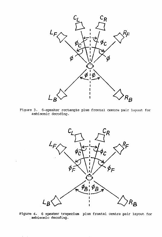
CL CR
Figure 3. 6-speaker rectangle plus frontal centre pair layout forambisonic decoding.
__ Z__
L_<>/ ! _>_Figure 4. 6 speaker trapezium plus frontal centre pair layout for
ambisonic decoding.

×
\
\
\
\
\
\
\
y< x
Figure 5. x- and y- rectangular coordinate conventions and azimuth
angle convention used in this paper.
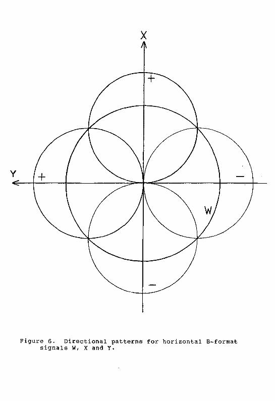
×
¥ +
Figure 6. Directional patterns for horizontal B-format
signals W, X and Y.

upZ
fronfX
?,,! \
\ b J'"' /I /,, --vt-Y-J-.. j
_' ... I / I /×_. % \_
Nt \ /,,/ '/
¥
toff
Figure 7. Directional polar patterns for full-sphereB-format signals W, X, Y, Z

f
Figure 8. Alterations of reproduced azimuth caused by6 dB forward dominance.

e_,lsumANOI-,CLlor
FREOUENGY,.gumAND [-_LF
-- DECODING -- DIFFERENCE}.->Ri:MATRIX
-- SUM AND
__ DIFFERENCE
y PHASE-COI_IPENSATEDBAND-SPLIT
HIGH*
FR£QUEIVOY
D£CODIh'O_4ATRIA'
Figure 9 . Architecbure of B-format ambisonic decoder for the speaker layouts of figs. 1 to 4.
E GAIN
i
I I I/ I 1
-IGC" -90: V 90' 180°
--1 8
F GAIN
' '-180 ° -90 ° 90 ° 8 o
1
Figure 10. Gain as a function of direction azimuth 0 for
the signals E (fig.lOa and F (fig.lOb) for QS = 600,
O B = 70 © and k e = kf = k b = 1.

CF
w sc _:) _isuMAND_cL, _ .)____DIFFERENCE_-.,.CROR CF5-OR6-MF
x -5_EAKE_ _ _uMAND_L_
y //(_ DECODERMB ' SUm AND _LBSB ,.DIFFERENCEI >RB
PHASE
CO/dPE//SAT/ONgEE IAu_l _- g,b,--
'1ALL'PASSI t' %FF
Figure 11. Decoder for enhanced Ambisonic B-format signals, showing input "cancellation"followed by direct feeds to the outputs. Simplified schematic.
J