Presented at CORROSION/2000 Paper No. 00626 · PDF filePresented at CORROSION/2000 Paper No....
15
Presented at CORROSION/2000 Paper No. 00626 Copyrighted © by NACE International Corrosion Testing Laboratories, Inc. 60 Blue Hen Drive, Newark, DE 19713 ANT-NEST CORROSION – DIGGING THE TUNNELS Richard A. Corbett Corrosion Testing Laboratories, Inc. 60 Blue Hen Drive Newark, DE 19713 Peter Elliott Corrosion and Materials Consultancy, Inc. P.O. Box 37 Colts Neck, NJ 07722 ABSTRACT Approximately 10% of all preliminary failures of copper tubes used in the HVAC industry are the direct result of ant-nest corrosion on a worldwide scale. This unusual form of localized corrosion has been detected in new tubes from some manufacturers, as well as early in service (i.e., less than one year). Laboratory studies have replicated service failures. The sources of the corrosive species that promote this form of attack are considered. Key words: Ant nest, formicary, pitting, copper, micro-tunnels, organic acids, formic acid, heat exchangers, air conditioning, lubricating fluids INTRODUCTION This is the continuing saga into a very insidious form of corrosion apparently limited to refrigeration grade copper (i.e., DHP copper, UNS C12200) although other forms of attack, similar in appearance, have been observed in other alloys. (1 – 5) This very localized attack is known as “ant-nest corrosion” (a.k.a. formicary corrosion). A previous review of this phenomenon (6) describes the mechanism where the copper base-metal oxidizes to form copper oxides and copper carboxylates (primarily copper formate). The literature provides several attempts to classify the morphology of ant-nest corrosion (6, 7) although no individual pattern has been identified. Laboratory studies (7, 9 - 14) have been successful in replicating ant-nest corrosion found in the field using carboxylic acids, hydrochloro- solvents, and petroleum- and water-based drawing and finning
Transcript of Presented at CORROSION/2000 Paper No. 00626 · PDF filePresented at CORROSION/2000 Paper No....
Presented at CORROSION/2000 Paper No. 00626 Copyrighted © by NACE International Corrosion Testing Laboratories, Inc. 60 Blue Hen Drive, Newark, DE 19713
ANT-NEST CORROSION – DIGGING THE TUNNELS
Richard A. Corbett
Corrosion Testing Laboratories, Inc. 60 Blue Hen Drive Newark, DE 19713
Peter Elliott
Corrosion and Materials Consultancy, Inc. P.O. Box 37
Colts Neck, NJ 07722
ABSTRACT Approximately 10% of all preliminary failures of copper tubes used in the HVAC industry are the direct result of ant-nest corrosion on a worldwide scale. This unusual form of localized corrosion has been detected in new tubes from some manufacturers, as well as early in service (i.e., less than one year). Laboratory studies have replicated service failures. The sources of the corrosive species that promote this form of attack are considered. Key words: Ant nest, formicary, pitting, copper, micro-tunnels, organic acids, formic acid, heat exchangers, air conditioning, lubricating fluids
INTRODUCTION This is the continuing saga into a very insidious form of corrosion apparently limited to refrigeration grade copper (i.e., DHP copper, UNS C12200) although other forms of attack, similar in appearance, have been observed in other alloys. (1 – 5) This very localized attack is known as “ant-nest corrosion” (a.k.a. formicary corrosion). A previous review of this phenomenon (6) describes the mechanism where the copper base-metal oxidizes to form copper oxides and copper carboxylates (primarily copper formate). The literature provides several attempts to classify the morphology of ant-nest corrosion (6, 7) although no individual pattern has been identified. Laboratory studies (7, 9 - 14) have been successful in replicating ant-nest corrosion found in the field using carboxylic acids, hydrochloro- solvents, and petroleum- and water-based drawing and finning
Presented at CORROSION/2000 Paper No. 00626 Copyrighted © by NACE International Corrosion Testing Laboratories, Inc. 60 Blue Hen Drive, Newark, DE 19713
lubricants. Case studies reported in the past two years suggest that this form of attack continues to be a problem in the heating, ventilation and air conditioning (HVAC) industry. (6, 15) It is reiterated that approximately 10% of all preliminary failures of copper tubes used in the HVAC industry are the direct result of ant-nest corrosion on a worldwide scale. (6, 9, 16, 17)
This paper reviews not only the current understanding of the mechanism of attack but cites new case studies including a thorough investigation into the cause of over 160 crates of new copper condenser and evaporator tubes that were affected by this form of attack.
MECHANISM REVIEW Residual organic compounds that remain on copper tubes during production and fabrication into chiller units, are able to advance to ant-nest corrosion only with the simultaneous presence of moisture, air and the decomposition of the organics to acids. It is concluded that the mechanism of the ant-nest corrosion is a modified pitting process involving a very small pit (termed a “micro-anode”) where the copper base-metal oxidizes and dissolves according to: Cuº Cu+ + e- (1) In the presence of carboxylic acid (e.g., formic acid) the copper ions react to form an unstable copper (I) complex: Cu+ + HCOO- Cu(CHOO) (2) This species is further oxidized to form a copper (II) carboxylate (e.g., copper (II) formate) and copper (I) oxide (cuprite): 4 Cu(CHOO) + ½ O2 2 Cu(CHOO)2 + Cu2O (3) Copper (II) formate has a monoclinic crystalline form and is blue in color. Micro-cracks develop and radiate outward within the pit due to the wedging effect of the deposited copper (I) and copper (II) complexes. The micro-cracks expose more surfaces of copper and the process proceeds within the micro-crack to give the copper (I) complex according to: Cu(CHOO)2 + Cuº 2 Cu(CHOO) (4) Thereon, reactions 3 and 4 repeat over and over until tunnels are formed leading to ultimate through-wall penetration. If, however, there is any disruption in the presence of the basic three components (i.e., moisture, air and organic acid), then the micro-cell mechanism shuts down and ant-nest corrosion ceases to propagate. Therefore, a tube may be infected with ant-nest corrosion but failure has not resulted in a leak.
Presented at CORROSION/2000 Paper No. 00626 Copyrighted © by NACE International Corrosion Testing Laboratories, Inc. 60 Blue Hen Drive, Newark, DE 19713
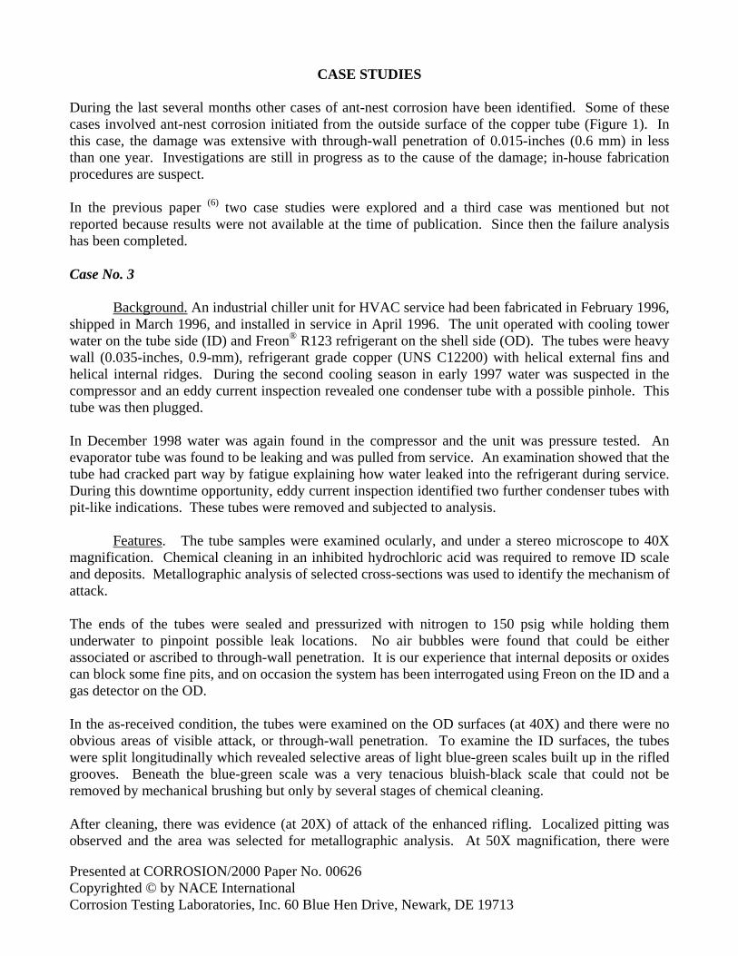
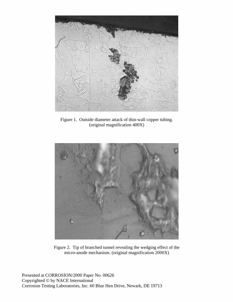
CASE STUDIES During the last several months other cases of ant-nest corrosion have been identified. Some of these cases involved ant-nest corrosion initiated from the outside surface of the copper tube (Figure 1). In this case, the damage was extensive with through-wall penetration of 0.015-inches (0.6 mm) in less than one year. Investigations are still in progress as to the cause of the damage; in-house fabrication procedures are suspect. In the previous paper (6) two case studies were explored and a third case was mentioned but not reported because results were not available at the time of publication. Since then the failure analysis has been completed. Case No. 3
Background. An industrial chiller unit for HVAC service had been fabricated in February 1996, shipped in March 1996, and installed in service in April 1996. The unit operated with cooling tower water on the tube side (ID) and Freon® R123 refrigerant on the shell side (OD). The tubes were heavy wall (0.035-inches, 0.9-mm), refrigerant grade copper (UNS C12200) with helical external fins and helical internal ridges. During the second cooling season in early 1997 water was suspected in the compressor and an eddy current inspection revealed one condenser tube with a possible pinhole. This tube was then plugged. In December 1998 water was again found in the compressor and the unit was pressure tested. An evaporator tube was found to be leaking and was pulled from service. An examination showed that the tube had cracked part way by fatigue explaining how water leaked into the refrigerant during service. During this downtime opportunity, eddy current inspection identified two further condenser tubes with pit-like indications. These tubes were removed and subjected to analysis.
Features. The tube samples were examined ocularly, and under a stereo microscope to 40X magnification. Chemical cleaning in an inhibited hydrochloric acid was required to remove ID scale and deposits. Metallographic analysis of selected cross-sections was used to identify the mechanism of attack. The ends of the tubes were sealed and pressurized with nitrogen to 150 psig while holding them underwater to pinpoint possible leak locations. No air bubbles were found that could be either associated or ascribed to through-wall penetration. It is our experience that internal deposits or oxides can block some fine pits, and on occasion the system has been interrogated using Freon on the ID and a gas detector on the OD. In the as-received condition, the tubes were examined on the OD surfaces (at 40X) and there were no obvious areas of visible attack, or through-wall penetration. To examine the ID surfaces, the tubes were split longitudinally which revealed selective areas of light blue-green scales built up in the rifled grooves. Beneath the blue-green scale was a very tenacious bluish-black scale that could not be removed by mechanical brushing but only by several stages of chemical cleaning. After cleaning, there was evidence (at 20X) of attack of the enhanced rifling. Localized pitting was observed and the area was selected for metallographic analysis. At 50X magnification, there were
Presented at CORROSION/2000 Paper No. 00626 Copyrighted © by NACE International Corrosion Testing Laboratories, Inc. 60 Blue Hen Drive, Newark, DE 19713
numerous pit indications. All pit locations were within the bluish-black scale that covered random areas of the tube’s interior surfaces. At high magnification (200X) the cross-sectional examination revealed branched tunnels within the metal. The tunnels were partially filled with a monoclinic, bluish colored product. At 2000X magnification, the tips of the tunnels revealed the wedging effect of the “micro-anode” mechanism (Figure 2). The maximum depth of the pits was 0.010-inches (0.4 mm), or about 25% of the through-wall thickness.
Considerations. On rare occasions, such as this case, a blue-green corrosion product covers the fine pits associated with ant-nest corrosion. Otherwise, the appearance of the corrosion product is common to the classical pitting and corrosion of copper. This investigation concluded that ant-nest corrosion was present along the entire tube lengths and that probably all condenser tubes in the unit were affected. The reason why the depth of pitting was minimal was due to the short time frame between tube manufacture, fabrication and service start-up, i.e., less than two months. Often there are several months between fabrication and start-up where the infestations of ant-nest corrosion initiate and propagate under moist air storage conditions. Although there was no evidence of a through-wall penetration in the condenser tubes, the possibility of leakage due to ant-nest corrosion is believed to be 50% within one year of service, but drops off to about 10% after three years. The reason for this trend in ant-nest corrosion probability is believed to be that the corrosion species (carboxylic acids) are flushed out of the pits during service. However, the remaining voids could entrap other corrosion species that can further propagate pitting damage. Replacement of the tubes becomes an economic and customer relations’ issue that can only be addressed by the chiller manufacturer. The recommendation to pull random tubes for analysis to determine if the ant-nest pits are propagating will be assessed during the year 2000 winter shutdown.
LABORATORY STUDIES
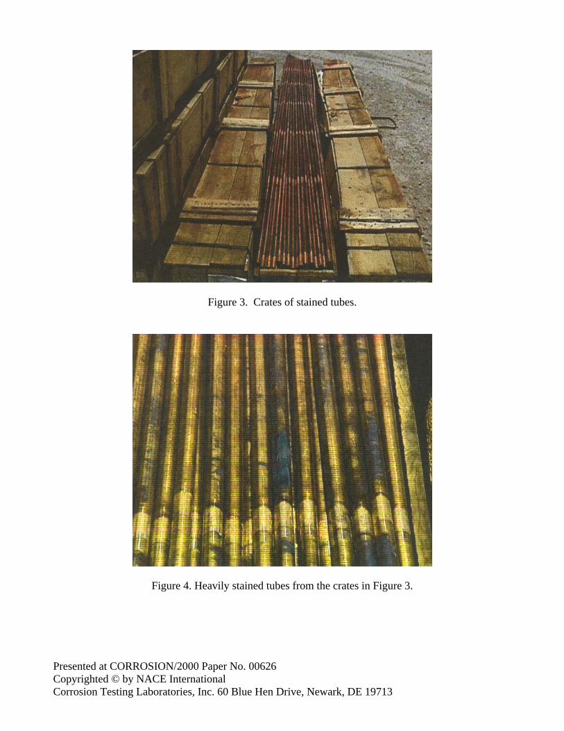
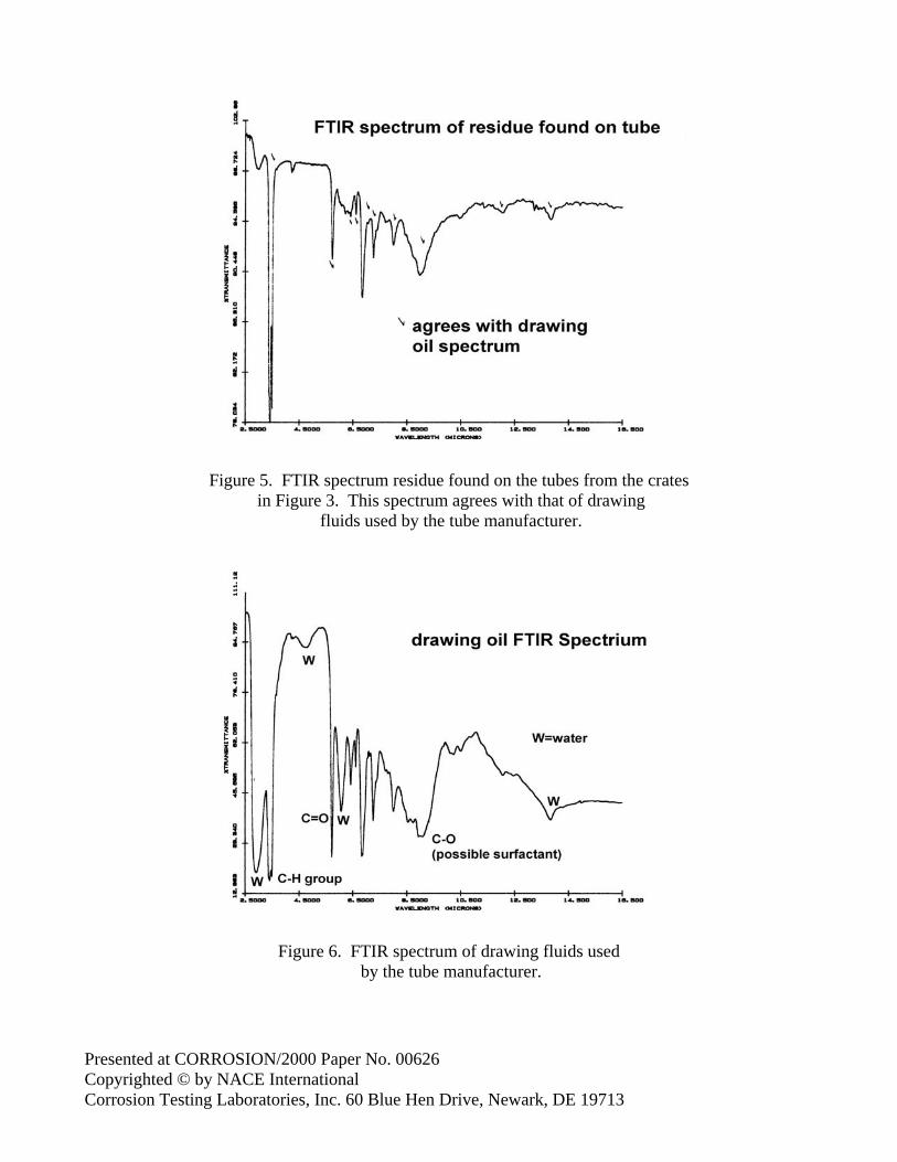
Service Failure One hundred sixty five (165) crates of finned copper tubes had been shipped from the tube manufacturer approximately two weeks prior to opening the boxes at a chiller fabricator. During the interim period, the crates were stored under cover in a warehouse. Upon opening the crates it became obvious that something was amiss. Instead of being bright and shiny, the tubes were heavily stained along their entire length (Figures 3 and 4). The stains ranged in color from bluish-green to brown and black. Several random tubes were selected to identify the composition of the stains. The outside surfaces were wire brushed and the dust collected for Fourier Transformation Infrared (FTIR) analysis. The spectra agreed with the textbook reference for copper (II) carbonate (basic), but also showed traces of hydrocarbon material. To resolve the hydrocarbon issue, the OD surfaces of the tubes were washed with chloroform to dissolve any organics prior to examination using FTIR. The resultant infrared spectra showed a good correlation of bands that agreed with the drawing oil (mostly ester with some long-chain hydrocarbon functionality) and finning lubricant (a complex mixture of materials including water, ester and long-chain hydrocarbons, plus some glycol and/or ethylene oxide materials [surfactants]) used by the tube manufacturer (Figures 5 and 6).
Presented at CORROSION/2000 Paper No. 00626 Copyrighted © by NACE International Corrosion Testing Laboratories, Inc. 60 Blue Hen Drive, Newark, DE 19713
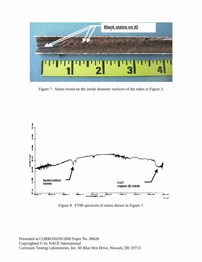
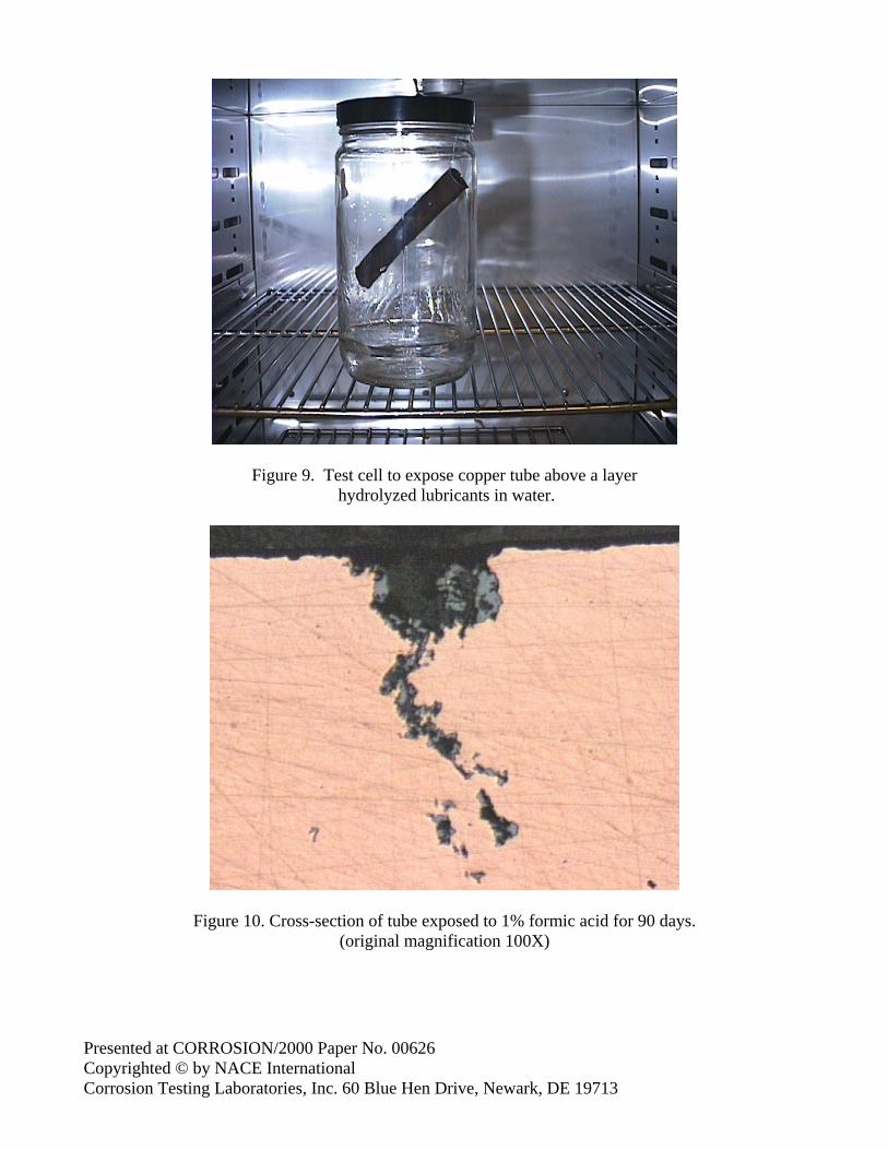
The inside tube surfaces were also stained (Figure 7), but unlike the OD stains, these stains were all black and were predominately located in valleys of the internal rifling. A small amount of potassium bromide (KBr) was placed over the spots inside the tube, and the black material was scraped loose, mixing with the KBr for FTIR analysis. The resultant spectra identified some hydrocarbon bands as well as identifying the bulk of the product as copper (II) oxide (Figure 8). It was concluded that much of the contaminant on the tube’s OD was copper carbonate with a small residual of the drawing and finning lubricants. It was discovered that the copper tube manufacturer had recently changed its water source to well water high in carbon dioxide content, which is known to aggressively attack copper, often forming a copper carbonate scale. The finning lubricant was a water-soluble, ester–based oil. These oils are known to be able to decompose (hydrolyze) to carboxylic acids (e.g. formic, acetic, etc.) A sample was analyzed for total acid content and was found to approximately 23% acidic. An on-site review of the procedures used for finning the copper tubes found that during the last stages of manufacture the tubes were bundled and soaked in a vat of hot water to remove the water soluble finning and drawing lubricants. The water bath was infrequently changed out during the production of these 165 crates of tubes and the residual finning and drawing oils were not completely removed from the tubes. Laboratory Simulations Laboratory studies have been carried out replicating the works of Hamamoto, et al. (10), Takahashi, et al (11) and Notoya (13, 18, 19). The corrodents examined included 1% formic acid as the control, two finning and two drawing lubricants, plus as-received stained tubes from several of the 165 crates with the black deposits on the ID. Mixing 190mL of lubricant with 10mL of deionized water and heat refluxed at 176°C for 100 hrs thermally decomposed the lubricants. The copper tubes were smooth on the OD with internal rifling on the ID, had a wall thickness of 0.030-inches (0.76-mm) and were 4-inches (100-mm) in length. The stained tubes were cut to length and left in the as-received condition. The copper tubes were suspended above 100mL of water containing 10ml of hydrolyzed lubrication oils in an airtight one-quart (0.95L), screw lid jar in a constant temperature oven (Figure 9). The tubes did not come into direct contact with the test solution but were suspended above it with Teflon® thread. The as-received tubes were suspended above deionized water. Oxygen is one of the three ingredients required for ant-nest corrosion; therefore the atmosphere above the solution was charged with ozone prior to sealing the test jar. This procedure would ensure and adequate supply of oxygen to the humid atmospheres knowing that the ozone is short-lived before decomposing to oxygen. Notoya (20) has reported that temperatures above ambient are conducive to accelerated attack and that thermal cycling is even more severe. For the experiments carried out, the temperatures were changed from 25°C to 40°C on an 8 hour / 16 hour cycle. This attempted to replicate extreme warehouse storage condition for manufactured and fabricated tubes. The exposure period was 90 days, after which time the tubes were split longitudinally and examined under a microscope at 40X magnification.
Presented at CORROSION/2000 Paper No. 00626 Copyrighted © by NACE International Corrosion Testing Laboratories, Inc. 60 Blue Hen Drive, Newark, DE 19713
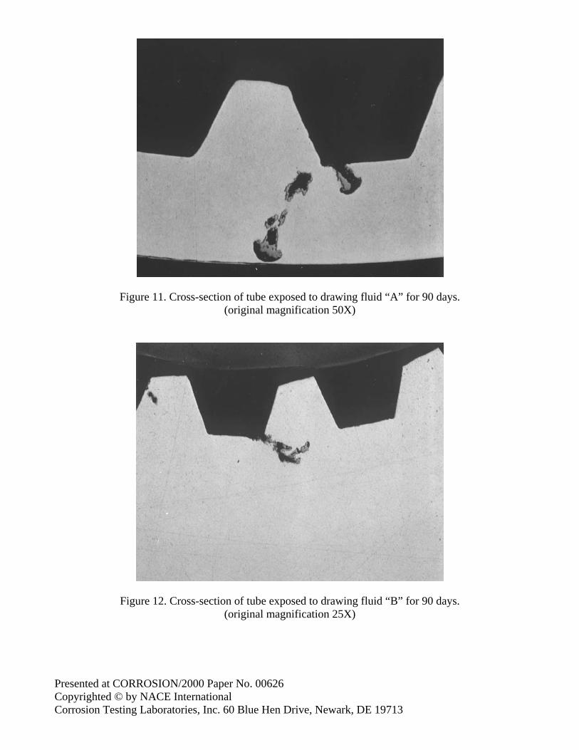
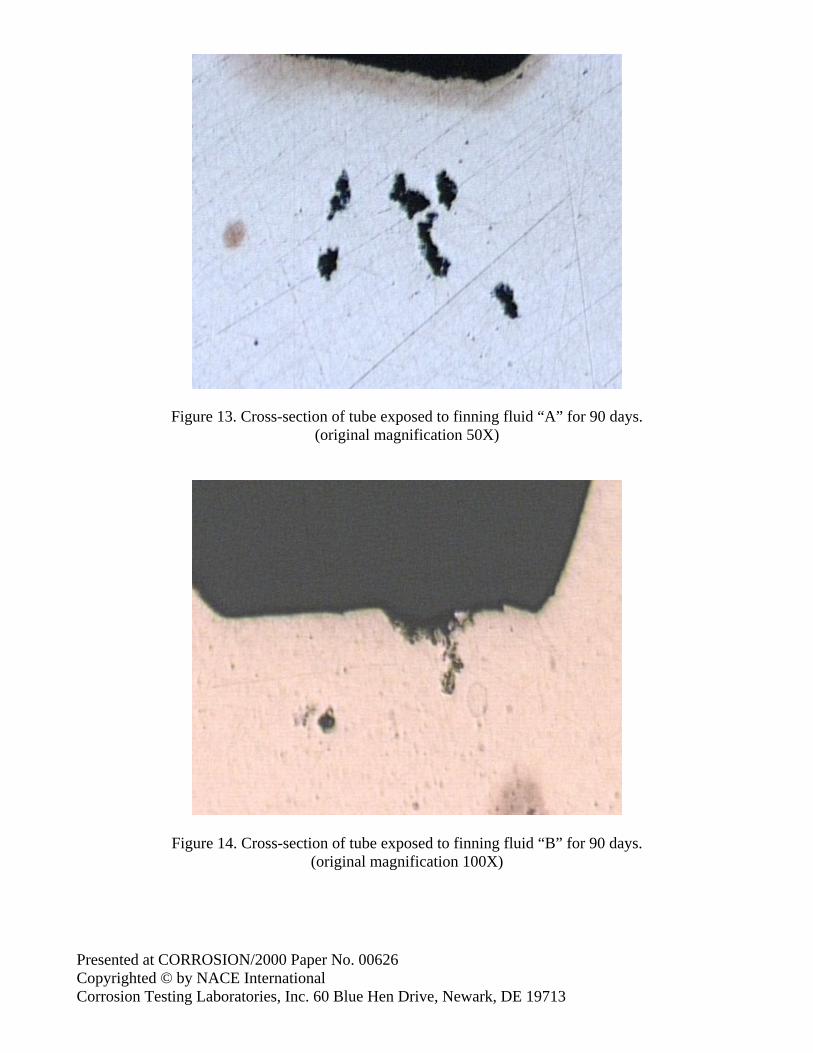
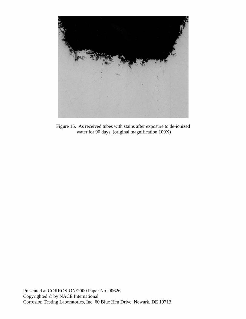
Results. Surface staining occurred on all tests copper samples. The coloration varied from dark purple to dark blue-green to blue-gray to black. The as-received tubes had tarnished to a light brown patina, however the black stains remained. Cross-sections of the tubes after exposure revealed localized attack. In the formic acid, the presence of branched tunnels was obvious (Figure 10). In the drawing fluids, one tube had circular pits only (Figure 11) while the other had branched tunnels (Figure 12). In the finning fluids, both tubes had branched tunnels (Figures 13 and 14). The as-received tubes displayed the beginnings of branched tunnels (Figure 15).
DISCUSSION Once considered to be a strange and unusual type of localized pitting, the type of corrosion observed during this investigation is known as “ant-nest” or “formicary” corrosion due to its unique morphology. Pits created by this type of corrosion are so fine that they are not visible to the un-aided eye. Only discoloration of a bluish gray to black scale might be recognizable around the pits. Our studies and those of others have cautioned that ant-nest corrosion arises because of the presence of undesirable organic species (notably carboxylic acids) on copper tube surfaces. ASTM B 743(21) calls for certain minimum cleanliness levels for refrigeration or air conditioning grades of copper tube. Typically, the inside tube surface shall be sufficiently clean so that when the ID is washed with a suitable solvent (redistilled chloroform or trichlorethylene) the residue remaining upon evaporation of the solvent shall be less than 0.0035 g/ft2 (0.038 g/m2) of the interior surface. There have been several developments in the area of drawing and finning lubricants, notably the advent of water-based synthetic fluids and those that are described as self-evaporative (or semi-evaporative) oils that require no further post-cleaning. Lubricant manufacturers proclaim the use of alternative fluids to solvent cleaners, including free-rinsing oils, water-soluble oils and self/semi-evaporative oils. Such fluids are apparently industry-proven and are compatible with vapor degreasing solvents and Freon, etc. However, self-evaporating lubricating oils have been implicated in causing “ant-nest” corrosion (12, 22) and the effectiveness of surface cleaning warrants further study. It may also be noted that materials that react with water to form carboxylic acids include trichloroethane, trichloroethylene, methylene chloride and carbon tetrachloride, which are commonly used as cleaning solvents. Further, borofluoride-soldering fluxes and/or hydrogen fluoride fumes or other fluorides with refrigerant gases can all be air-oxidized to carboxylic acids. When ant-nest corrosion is identified, it is just as important to determine whether changes were made in the use of fabrication fluids as it is to fully determine the history of the tubes, from manufacture, storage, and transport to ultimate fabrication.
REFERENCES 1. I. LeMay, N. O. Beltran, “Metallography and Corrosion,” Proc. Metallography and Corrosion
Symposium, NACE (1986): p 119. 2. R. A. Corbett, W. S. Morrison, D. F. Bickford, Materials Performance, 26, 2 (1987): p. 40.
Presented at CORROSION/2000 Paper No. 00626 Copyrighted © by NACE International Corrosion Testing Laboratories, Inc. 60 Blue Hen Drive, Newark, DE 19713
3. M. J. Esmacher, Materials Performance, 26, 5 (1987): p. 17. 4. F. H. Seels, Materials Performance, 26, 5 (1987): p. 29. 5. J. T. Welz, J. C. Tverberg, Materials Performance, 37, 5 (1998): p. 66. 6. P. Elliott, R. A. Corbett, CORROSION/99, paper number 99342, (Houston, TX: NACE
International, 1999). 7. S. Yamauchi, K. Nagata, S. Sato, M. Shimono, Journal Of The Japanese Copper and Brass
Research Association 22 (1983): p 132, also Sumitomo Light Metal Technical Reports, 25, 1 (1984): p. 1.
8. Japanese Petroleum Society: Collected Photographs of Corrosion Morphology, Revised Edition (1968): p. 189.
9. T. Notoya, T. Hamamoto, K. Kawano, Sumitomo Light Metal Technical Reports, 30, 3 (1989): p. 9.
10. T. Hamamoto, M. Imai, Sumitomo Light Metal Technical Reports, 33, 4 (1991): p. 23. 11. T. Takahashi, et. al., Journal of the Japan Copper and Brass Research Association, 31 (1992): p.
135. 12. Miyafuji, et. al., Journal of the Copper and Brass Research Association, 33 (1994): p. 7. 13. H. Baba, T. Kodama, Corrosion Engineering (Japan) 44, 4 (1995): p. 279. 14. T. Notoya, Zairya-to-Kankyo, 46 (1997): p. 731. 15. G. Tetley, M. Heidenreich, K. Smith, Air Conditioning, Heating & Refrigeration News, 203, 13
(1998): p. 5 (personnel communication G. Tetley). 16. T. Notoya, Corrosion Engineering, 39 (1990): p. 353. 17. G. Isobe, et. al., NACE Corrosion Asia, paper 106 (1992). 18. T. Notoya, T. Hamamoto, K. Kawano, Corrosion Engineering (Japan), 37, 2 (1988): p. 1. 19. T. Notoya, Materials Performance, 32, 5 (1993): p. 53. 20. T. Notoya, Corrosion and Prevention/97, paper number 002, (Brisbane, Australia, 1997). 21. Annual Book of ASTM Standards, volume 02.01 (Conshohocken, PA). 22. R. S. Lenox, P. A. Hough, ASHRAE Journal, 11 (1995): p. 50.
Presented at CORROSION/2000 Paper No. 00626 Copyrighted © by NACE International Corrosion Testing Laboratories, Inc. 60 Blue Hen Drive, Newark, DE 19713
Figure 1. Outside diameter attack of thin-wall copper tubing. (original magnification 400X)
Figure 2. Tip of branched tunnel revealing the wedging effect of the micro-anode mechanism. (original magnification 2000X)
Presented at CORROSION/2000 Paper No. 00626 Copyrighted © by NACE International Corrosion Testing Laboratories, Inc. 60 Blue Hen Drive, Newark, DE 19713
Figure 3. Crates of stained tubes.
Figure 4. Heavily stained tubes from the crates in Figure 3.
Presented at CORROSION/2000 Paper No. 00626 Copyrighted © by NACE International Corrosion Testing Laboratories, Inc. 60 Blue Hen Drive, Newark, DE 19713
Figure 5. FTIR spectrum residue found on the tubes from the crates in Figure 3. This spectrum agrees with that of drawing
fluids used by the tube manufacturer.
Figure 6. FTIR spectrum of drawing fluids used by the tube manufacturer.
Presented at CORROSION/2000 Paper No. 00626 Copyrighted © by NACE International Corrosion Testing Laboratories, Inc. 60 Blue Hen Drive, Newark, DE 19713
Figure 7. Stains found on the inside diameter surfaces of the tubes in Figure 3.
Figure 8. FTIR spectrum of stains shown in Figure 7.
Black stains on ID s rface
Presented at CORROSION/2000 Paper No. 00626 Copyrighted © by NACE International Corrosion Testing Laboratories, Inc. 60 Blue Hen Drive, Newark, DE 19713
Figure 9. Test cell to expose copper tube above a layer hydrolyzed lubricants in water.
Figure 10. Cross-section of tube exposed to 1% formic acid for 90 days. (original magnification 100X)
Presented at CORROSION/2000 Paper No. 00626 Copyrighted © by NACE International Corrosion Testing Laboratories, Inc. 60 Blue Hen Drive, Newark, DE 19713
Figure 11. Cross-section of tube exposed to drawing fluid “A” for 90 days. (original magnification 50X)
Figure 12. Cross-section of tube exposed to drawing fluid “B” for 90 days. (original magnification 25X)
Presented at CORROSION/2000 Paper No. 00626 Copyrighted © by NACE International Corrosion Testing Laboratories, Inc. 60 Blue Hen Drive, Newark, DE 19713
Figure 13. Cross-section of tube exposed to finning fluid “A” for 90 days. (original magnification 50X)
Figure 14. Cross-section of tube exposed to finning fluid “B” for 90 days. (original magnification 100X)
Presented at CORROSION/2000 Paper No. 00626 Copyrighted © by NACE International Corrosion Testing Laboratories, Inc. 60 Blue Hen Drive, Newark, DE 19713
Figure 15. As received tubes with stains after exposure to de-ionized water for 90 days. (original magnification 100X)