Presentation of the DriveLab Board Opal-RT Real-time institute 2009.
15
esentation of the DriveLab Boar Opal-RT Real-time institute 2009
-
Upload
alvin-parks -
Category
Documents
-
view
213 -
download
0
Transcript of Presentation of the DriveLab Board Opal-RT Real-time institute 2009.

Presentation of the DriveLab Board
Opal-RT Real-time institute 2009

Content
•DriveBoard description
Opal-RT Real-time institute 2009

DriveBoard description
The drives board which we use in the Electric Drives Laboratory has been designed to enable us to perform a variety of experiments on AC/DC machines.
The main features of the board are:
• Two completely independent 3-phase PWM inverters for complete simultaneous control of two machines• 42 V dc-bus voltage to reduce electrical hazards• Digital PWM input channels for real-time digital control• Complete digital/analog Real-Time system powered by Opal-RT Technologies
Opal-RT Real-time institute 2009

Driveboard description
Opal-RT Real-time institute 2009

DriveBoard Description

DriveBoard Description
Opal-RT Real-time institute 2009

DriveBoard description
Opal-RT Real-time institute 2009

DriveBoard description -Inverters
Opal-RT Real-time institute 2009
Each 3-phase inverter uses MOSFETs as switching devices. The 3-phase outputs of the first inverter are marked A1 (D-6 in Fig. 1.2), B1 (E-6 in Fig. 1.2), C1 (F-6 in Fig. 1.2) and those of the second inverter are marked A2 (I-6 in Fig. 1.2), B2 (K-6 in Fig. 1.2), C2 (L-6 in Fig. 1.2).

DriveBoard description -Inverters
Opal-RT Real-time institute 2009
DriveBoard description –Signal Supply
Opal-RT Real-time institute 2009
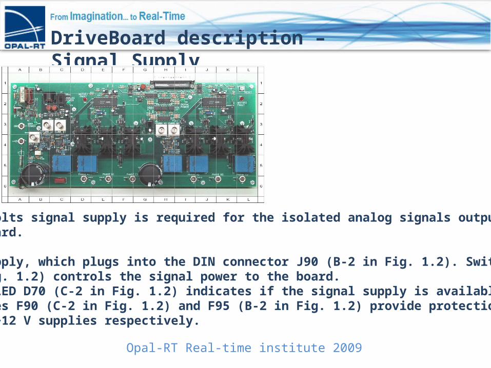
Each ±12 volts signal supply is required for the isolated analog signals output form the drives board.
A power supply, which plugs into the DIN connector J90 (B-2 in Fig. 1.2). Switch S90 (C-2 in Fig. 1.2) controls the signal power to the board. The green LED D70 (C-2 in Fig. 1.2) indicates if the signal supply is available to the board. Fuses F90 (C-2 in Fig. 1.2) and F95 (B-2 in Fig. 1.2) provide protection for the +12 V and −12 V supplies respectively.

DriveBoard description –Voltage measurement
Opal-RT Real-time institute 2009
Test points are provided to observe the inverter output voltages. BNC connector VOLT DC (B-4in Fig. 1.2) has been provided to sense the DC bus voltage.
To measure the DC bus voltage
• Connect a BNC cable to VOLT DC BNC connector.• The scaling factor of input voltage is 1/10.

DriveBoard description –Current measurement
Opal-RT Real-time institute 2009
LEM sensors are used to measure the output current of the inverters. Only A and B phase currents are sensed. The C phase current can then be calculated using the current relationship Ia+Ib+Ic = 0,assuming that there is no neutral connection for the machines.
The calibration of the current sensor is such that for 1 A current flowing through the current sensor, output is 0.5 V.

DriveBoard description –Current measurement
Opal-RT Real-time institute 2009
To measure the output current of phase A of inverter 1,Connect BNC connector to CURR A1 (B-3 in Fig. 1.2).To measure the output current of phase B of inverter 1,Connect BNC connector to CURR B1 (C-3 in Fig. 1.2).To measure the output current of phase A of inverter 2,Connect BNC connector to CURR A2 (H-3 in Fig. 1.2).To measure the output current of phase B of inverter 2,• Connect BNC connector to CURR B2 (I-3 in Fig. 1.2).

DriveBoard description –Component location
Opal-RT Real-time institute 2009

37 Pin DSUB Connectors