Presentation Electronic pressure sensors Osi For control ... · For control circuits type XML F...
46
30386-EN_Ver5.4.fm/2 Schneider Electric Presentation 4 Electronic pressure sensors 4 Nautilus ® Universal Osiconcept ® For control circuits type XML F Electronic pressure sensors type XML F are used for pressure control of hydraulic oils, fresh water, sea water, air and corrosive fluids, between - 1 and 600 bar. b Osiconcept : simplicity of setting-up Electronic pressure sensors type XML F are characterised by their ceramic pressure measuring cell. 1 Large 4-digit display indicating programming codes, parameter values or the measured pressure. 2 LED indicators for pressure unit of measurement selected (direct reading of bar or psi). 3 LED indicator(s) for providing status of pressure switch output(s). 4 Ergonomic keys for configuring the product via the scrolling menu. 5 Excellent resistance to overpressures. 6 Memorisation and possibility of reading pressure peaks within the installation. v Three menus enable the user to : - configure (“PROG” menu) the various functions of the unit (access to all the parameters of the product), - perform (“USER” menu) diagnostic operations and, for pressure switches, to set the switching point pressure values, - read (“READ” menu) all the configuration details, together with the values set in the “PROG” and “USER” menus. b Pressure sensors XML FpppD2p1p have a 4…20 mA or 0…10 V analogue output. In addition to having a manual diagnostic function (see below), they also incorporate a remote diagnostic function : a digital input connected, for example, to a PLC enables remote activation of the sensor’s test function. When the sensor is operating correctly, the analogue output must, when testing, be close to 50% of the sensor size (12 mA or 5 V). b Universal sensors XML FpppD2p2p are pressure switches with an adjustable differential, for regulation between 2 thresholds, featuring a solid state output (programmable both for NPN or PNP and NO or NC) and a 4…20 mA or 0…10 V analogue output. They incorporate the manual diagnostic function (see below). b Pressure switches XML FpppD2p3p are dual stage switches, with adjustable differential for each threshold, featuring 2 solid state outputs (programmable both for NPN or PNP and NO or NC). They incorporate the manual diagnostic function (see below). b Pressure switches for a.c. control XML-FpppE2p4p are switches with adjustable differential, for regulation between 2 thresholds, featuring an a 2.5 A output relay (programmable for NO or NC). They incorporate the manual diagnostic function (see below). Sensors type XML-F feature : b Various configurable functions v For the display - pressure unit of measurement (bar or psi), - response time (slow : display refreshes in 1% steps of the unit's size, normal : display refreshes in 0.5% steps of the unit's size or fast : display refreshes every 10 ms. v For the analogue output : - response time (adjustable from 5 to 500 ms, in steps of 1 ms), - maximum pressure of the output curve (adjustable from 75 to 125% of the unit's size). v For each solid state output : - PNP or NPN logic, - NO or NC contact, - time delay both on trip and on reset (adjustable from 0 to 50 s, in steps of 1 s), - response time (adjustable from 5 to 500 ms, in steps of 1 ms). v For the a.c. output via relay : - NO or NC contact, - time delay both on trip and on reset (adjustable from 0 to 50 s, in steps of 1 s), - response time (adjustable from 5 to 500 ms, in steps of 1 ms). b Manual diagnostic function enabling : - checking correct operation of sensor, - reading the value of the maximum pressure peak that has occurred since the last reset to zero and also, deleting this value for a fresh reset. Presentation Enter Menu Bar Psi Output 1 Output 2 1 6 5 4 2 3 Functions
Transcript of Presentation Electronic pressure sensors Osi For control ... · For control circuits type XML F...

30386-EN_Ver5.4.fm/2 Schneider Electric
Presentation 4 Electronic pressure sensors 4
Nautilus® Universal Osiconcept®For control circuits type XML F
Electronic pressure sensors type XML F are used for pressure control of hydraulic oils, fresh water, sea water, air and corrosive fluids, between - 1 and 600 bar.b Osiconcept : simplicity of setting-upElectronic pressure sensors type XML F are characterised by their ceramic pressure measuring cell.
1 Large 4-digit display indicating programming codes, parameter values or the measured pressure.
2 LED indicators for pressure unit of measurement selected (direct reading of bar or psi).
3 LED indicator(s) for providing status of pressure switch output(s).4 Ergonomic keys for configuring the product via the scrolling menu.5 Excellent resistance to overpressures.6 Memorisation and possibility of reading pressure peaks within the installation. v Three menus enable the user to :
- configure (“PROG” menu) the various functions of the unit (access to all the parameters of the product),
- perform (“USER” menu) diagnostic operations and, for pressure switches, to set the switching point pressure values,
- read (“READ” menu) all the configuration details, together with the values set in the “PROG” and “USER” menus.
b Pressure sensors XML FpppD2p1p have a 4…20 mA or 0…10 V analogue output. In addition to having a manual diagnostic function (see below), they also incorporate a remote diagnostic function : a digital input connected, for example, to a PLC enables remote activation of the sensor’s test function. When the sensor is operating correctly, the analogue output must, when testing, be close to 50% of the sensor size (12 mA or 5 V). b Universal sensors XML FpppD2p2p are pressure switches with an adjustable differential, for regulation between 2 thresholds, featuring a solid state output (programmable both for NPN or PNP and NO or NC) and a 4…20 mA or 0…10 V analogue output. They incorporate the manual diagnostic function (see below).b Pressure switches XML FpppD2p3p are dual stage switches, with adjustable differential for each threshold, featuring 2 solid state outputs (programmable both for NPN or PNP and NO or NC). They incorporate the manual diagnostic function (see below).b Pressure switches for a.c. control XML-FpppE2p4p are switches with adjustable differential, for regulation between 2 thresholds, featuring an a 2.5 A output relay (programmable for NO or NC). They incorporate the manual diagnostic function (see below).
Sensors type XML-F feature :b Various configurable functionsv For the display
- pressure unit of measurement (bar or psi),- response time (slow : display refreshes in 1% steps of the unit's size,
normal : display refreshes in 0.5% steps of the unit's size or fast : display refreshes every 10 ms.v For the analogue output :
- response time (adjustable from 5 to 500 ms, in steps of 1 ms),- maximum pressure of the output curve (adjustable from 75 to 125% of the unit's
size).v For each solid state output :
- PNP or NPN logic,- NO or NC contact,- time delay both on trip and on reset (adjustable from 0 to 50 s, in steps of 1 s),- response time (adjustable from 5 to 500 ms, in steps of 1 ms).
v For the a.c. output via relay :- NO or NC contact,- time delay both on trip and on reset (adjustable from 0 to 50 s, in steps of 1 s),- response time (adjustable from 5 to 500 ms, in steps of 1 ms).
b Manual diagnostic function enabling :- checking correct operation of sensor,- reading the value of the maximum pressure peak that has occurred since the last
reset to zero and also, deleting this value for a fresh reset.
Presentation
Enter
Menu
Bar
Psi
Output 1
Output 2
16
5
4
2
3
Functions

30386-EN_Ver5.4.fm/3Schneider Electric
Characteristics 4 Electronic pressure sensors 4
Nautilus® Universal Osiconcept®For control circuits type XML F
Environment characteristicsConforming to standards e,
IEC/EN 60947-1, IEC/EN 60947-5-1, EN 50081, EN 50082, EN 61000-6-2, EN 61000-4-2/3/4/5/6/8/11
Product certifications UL, CSAProtective treatment Standard version “TC”
Ambient air temperature Operation - 25…+ 80 °C (d.c. models)
- 25…+ 75 °C (a.c. models)Fluids or products controlled Hydraulic oils, air, fresh water, sea water, corrosive fluids, from - 15 to + 80 °CComponent materials of switchin contact with the fluid
Stainless steel fluid entry type AISI 303, viton seal
Operating position All positions
Vibration resistance 5 gn (25…200 Hz) and 35 gn (60…2000 Hz), conforming to IEC 68-2-6
Shock resistance 50 gn, conforming to IEC 68-2-27Electrical protection Against reverse polarity, short-circuit, overload and connection faults
Resistance to electromagnetic interference
Electrostatic discharges Standard EN 61000-4-2 contact 4kV Air 8 kVRadiated electromagnetic fields
Standard EN 61000-4-3 10 V/m
Fast transients Standard EN 61000-4-4 2 kV
Shock waves Standard EN 61000-4-5 (AC) 1 kV, (DC) 0.5 kVConducted disturbances, induced by radio-frequency fields
Standard EN 61000-4-6 10 V
Degree of protection IP 67 conforming to IEC/EN 60529, NEMA 4/6/12/13
Operating rate < 50 HzOutput response time Adjustable from 5 to 500, in steps of 1 ms
Service life Millions of operating cycles > 10
Drift Of the zero point < ± 0.1 % of the measuring range/°C
Of the sensitivity < ± 0.03 % of the measuring range/°C
Precision Analogue output � 0.6 % of the measuring range, output offset < 200 mVDigital output � 0.6 % of the measuring range
Repeat accuracy � 0.5 % of the measuring range
Display response time Adjustable. 3 options : - slow (1% of the unit's size), - normal (0.5% of the unit's size) or - fast (refreshed every 10 ms)
Fluid connections G 1/4 A (1/4" BSP female) conforming to NF E 03-004 and ISO 7, 1/4" NPT female or SAE 7�16-20UNF, depending on model
Electrical connections M12, “Snap-C” compatible, connector or SAE 7/8-16UN connector, depending on model

30387-EN_Ver3.3.fm/2 Schneider Electric
- 0,25 bar4 mA - 0 V
- 0,50 0,250
20 mA - 10 V
12 mA - 5 V
-1
PH
PB
Time
-1
-0,5
bar
2 1
-0,97bar
0-0,5 -0,05
-0,08
1 Maximum differential2 Minimum differential
Vacuum �
Adjustable value
Falli
ng p
ress
ure
Rising pressure
Accessories :page 30339/2
Dimensions :page 30339/3
Schemes :page 30339/3
Electronic pressure sensors 4
Nautilus®, type XML-FSize - 1 bar (- 14.5 psi)
(1) Vacuum sensors with adjustable differential for regulation between 2 thresholds. Solid state output and analogue output.(2) Fluids controlled : hydraulic oils, fresh water, sea water, air, corrosive fluids, from - 15 to + 80 °C. Component materials of sensor in contact with the fluid,see page 30386/3.
Type Analogue sensorsUniversal sensors with adjustable differ-ential. Solid state and analogue outputs (1)
Adjustable range of switching – - 0.08…- 1 bar (- 1.16…- 14.5 psi)point (PB) (Falling pressure)
Analogue output 4-20 mA 0-10 V 4-20 mA 0-10 V
References
Fluid connection 1/4" BSP female XML-FM01D2015 XML-FM01D2115 XML-FM01D2025 XML-FM01D2125(2)
1/4" NPT female XML-FM01D2016 XML-FM01D2116 XML-FM01D2026 XML-FM01D2126
SAE 7/16-20UNF XML-FM01D2019 XML-FM01D2119 XML-FM01D2029 XML-FM01D2129
Weight (kg) 0.480 0.480 0.480 0.480
Complementary characteristics not shown under general characteristics (page 30386/3)
Possible differential – Min. at low and high setting : 0.03 bar (0.44 psi) (add to PB to give PH) Max. at low setting : 0.95 bar (13.77 psi)Max. permissible accidental pressure 3 bar (43.5 psi)
Destruction pressure 5 bar (72.5 psi)
Rated supply voltage c 24 V
Voltage limits c 17…33 V
Current consumption 80 mA 80 mA
Output – Programmable NPN or PNP and NO or NCAdjustable time delay on trip and on reset
Time delay – from 0 to 50 s, in steps of 1 second
Switching capacity – 200 mA
Analogue output 4…20 mA or 0…10 V, depending on model. Maximum signal level adjustable between - 0.25 & 0.25 bar (- 3.62 & 3.62 psi)
Electrical connection M12, 4 contact, male connector. For suitable female connectors and extension cables, see page 30339/2Analogue output curve Vacuum sensor operating curves
References,characteristics 0

30387-EN_Ver3.3.fm/3Schneider Electric
PH1
PH2
PB2
PB1
-1
-0,5
bar
2 1
-0,97bar
0-0,5 -0,05
-0,08
PH
PB
1 Maximum differential2 Minimum differential
Fal
ling
pres
sure
Rising pressure
��Adjustable value
Time
Vacuum
� Adjustable value
Time
Vacuum
Electronic pressure sensors 4
Nautilus®, type XML-FSize - 1 bar (- 14.5 psi)
Vacuum switch operating curves
(1) Vacuum switches with adjustable differential for regulation between 2 thresholds. Relay output.(2) Vacuum switches with 2 adjustable stages and adjustable differential for each threshold. Solid state outputs.(3) Fluids controlled : hydraulic oils, fresh water, sea water, air, corrosive fluids, from - 15 to + 80 °C. Component materials of sensor in contact with the fluid,see page 30386/3.
Type Vacuum switches with adjustabledifferential and relay output (1)
Dual stage adjustable vacuum switcheswith solid state outputs (2)
Adjustable range of switching - 0.08…- 1 bar (-1.16…- 14.5 psi) - 0.08…- 1 bar (-1.16…- 14.5 psi)point(s) (PB or PB1 & PB2)(Falling pressure)
References
Fluid connection 1/4" BSP female XML-FM01E2045 XML-FM01D2035(3)
1/4" NPT female XML-FM01E2046 XML-FM01D2036
SAE 7/16-20UNF XML-FM01E2049 XML-FM01D2039
Weight (kg) 0.590 0.480
Complementary characteristics not shown under general characteristics (page 30386/3)
Possible differential (add to : Min. at low and high setting : 0.03 bar (0.44psi) For each stage:- PB to give PH Max. at low setting : 0.95 bar (13.77 psi) Min. at low and high setting : 0.03 bar (0.44psi)- PB1 & PB2 to give PH1 & PH2) Max. at low setting : 0.95 bar (13.77 psi)Max. permissible accidental pressure 3 bar (43.5 psi)
Destruction pressure 5 bar (72.5 psi)
Rated supply voltage a 120 V c 24 V
Voltage limits a 102…132 V c 17…33 V
Current consumption 32 mA 80 mA
Output Relay Programmable NPN or PNP and NO or NC
Time delay Adjustable time delay on trip and on reset from 0 to 50 s, in steps of 1 second
Switching capacity 2.5 A, AC-15, C300 (120 V - 1.5 A) 200 mASAE 7/8-16UN, 5 contact, male connector. For suitable M12, 4 contact, male connector. For suitable female
Electrical connection female extension cables, see page 30339/2. connectors and extension cables, see page 30339/2.
(curve for each stage for dual stage vacuum switches) Vacuum switches with relay output Dual stage vacuum switches
References,characteristics (continued) 0
Accessories :page 30339/2
Dimensions :page 30339/3
Schemes :page 30339/3

30397-EN_Ver2.2.fm/2 Schneider Electric
Electronic pressure sensors 4
Nautilus®, type XML-FRating 1 bar (14.5 psi)
(1) Pressure switches with adjustable difference for regulation between 2 thresholds, with solid-state output and analogue output.(2) Type of fluids monitored: hydraulic fluids, fresh water, seawater, air, corrosive fluids, from - 15 to + 80 °C. Component materials of sensor in contact with thefluid, see page 30386/3.
Type Analogue sensorsUniversal sensors with adjustable differ-ential. Solid state and analogue outputs (1)
High point (PH) adjustment range – 0.08…1 bar (1.16…14.5 psi) (Increasing pressure)
Analogue output 4-20 mA 0-10 V 4-20 mA 0-10 V
References
Hydraulic connection
1/4" gas female XML-F001D2015 XML-F001D2115 XML-F001D2025 XML-F001D2125
(2) 1/4" NPT female XML-F001D2016 XML-F001D2116 XML-F001D2026 XML-F001D2126
SAE 7/16-20UNF XML-F001D2019 XML-F001D2119 XML-F001D2029 XML-F001D2129
Weight (kg) 0.480 0.480 0.480 0.480
Complementary characteristics (page 30386/3)
Feasible difference – Min. at bottom and top of range: 0.03 bar (0.44 psi)to be subtracted from PH to obtain PB Max. at top of range: 0.95 bar (13.77 psi)Max. permissible accidental pressure 4 bar (58 psi)
Minimum breaking pressure 6 bar (87 psi)
Rated supply voltage c 24 V
Voltage limits c 17…33 V
Current consumption 80 mA 80 mAOutput – Programmable, NPN or PNP, on opening “O” or on closing
“C”Time delay – On closing or opening, adjustable from 0 to 50 s, in steps of 1
secondSwitching capacity – 200 mAAnalogue output 4…20 mA or 0…10 V, depending on model. Signal maximum level adjustable between 0.75 and 1.25 bar (10.88 and
18.12 psi)
Electrical connection By M12 connector, male, 4 contacts. Adaptable female connectors and extension cables, see page 30339/2Analogue output curve Pressure switch operating curves
0,75 bar4 mA - 0 V
0,5 1,251
20 mA - 10 V
12 mA - 5 V
0
1
0,08
0,05 0,97bar
0,5
bar
0 0,5
21
1 Maximum differential2 Minimum differential
Decreasing pressure
Incr
easi
ng p
ress
ure
PH
PB
Pressure
Time � Adjustable value
References, characteristics 0
Accessories:page 30339/2
Dimensions:page 30339/3
Diagrams:page 30339/3

30397-EN_Ver2.2.fm/3Schneider Electric
Electronic pressure sensors 4
Nautilus®, type XML-FRating 1 bar (14.5 psi)
Pressure switch operating curves
(1) Pressure switches with adjustable difference for regulation between 2 thresholds, with output relay.(2) Adjustable 2-stage pressure switches and difference adjustable at each threshold, with solid-state outputs.(3) Type of fluids monitored: hydraulic fluids, fresh water, seawater, air, corrosive fluids, from - 15 to + 80 °C. Component materials of sensor in contact with thefluid, see page 30386/3.
Units
Adjustment range of upper point(s) (PH or PH1 and PH2) (Increasing pressure)
0.08…1 bar (1.16…14.5 psi) 0.08…1 bar (1.16…14.5 psi)
References
Hydraulic 1/4" gas female XML-F001E2045 XML-F001D2035connection(3) 1/4" NPT female XML-F001E2046 XML-F001D2036
SAE 7/16-20UNF XML-F001E2049 XML-F001D2039
Weight (kg) 0.590 0.480
Complementary characteristics (page 30386/3)
Feasible difference to be subtracted Min. at bottom and top of range: 0.03 bar (0.44 psi) For each stage:- from PH to obtain PB Max. at top of range: 0.95 bar (13.77 psi) Min. at bottom and top of range: 0.03 bar (0.44 psi)- from PH1 and PH2 to obtain PB1 and PB2
Max. at top of range: 0.95 bar (13.77 psi)
Max. permissible accidental pressure
4 bar (58 psi)
Minimum breaking pressure 6 bar (87 psi)
Rated supply voltage a 120 V c 24 V
Voltage limits a 102…132 V c 17…33 V
Current consumption 32 mA 80 mA Output Relay Programmable, NPN or PNP, on opening “O” or on
closing “C”
Time delay On closing or opening, adjustable from 0 to 50 s, in steps of 1 secondSwitching capacity 2.5 A, AC-15, C300 (120 V - 1.5 A) 200 mAElectrical connection By SAE 7/8-16UN connector, male, 5 contacts.
Adaptable female extension cables, see page 30339/2 By M12 connector, male, 4 contacts. Adaptable female connectors and extension cables, see page 30339/2
(curve for each stage for 2-stage pressure switches) Pressure switches with output relay 2-stage pressure switches
1
0,08
0,05 0,97bar
0,5
0 0,5
21
1 Maximum differential2 Minimum differential
Decreasing pressure
Incr
easi
ng p
ress
ure
PH
PB
Pressure
Time � Adjustable value
PH2
PH1
PB1
PB2
Pressure
Time � Adjustable value
References, characteristics (continued) 0
Accessories:page 30339/2
Dimensions:page 30339/3
Diagrams:page 30339/3
Dual stage adjustable pressure switches with solid state outputs (2)
Pressure switches with adjustable differential and relay output (1)

30388-EN_Ver3.3.fm/2 Schneider Electric
PH
PB
1 1,9 bar4 mA - 0 V
3,1
20 mA - 10 V
12 mA - 5 V
0 2,5
2,5
0,20
0,12 2,42 bar
1
bar
0 1
21
2
2
References,characteristics 0
1 Maximum differential2 Minimum differential
Falling pressure
Ris
ing
pres
sure
Pressure
Time
Accessories :page 30339/2
Dimensions :page 30339/3
Schemes :page 30339/3
Electronic pressure sensors 4
Nautilus®, type XML-FSize 2.5 bar (36.25 psi)
(1) Pressure sensors with adjustable differential for regulation between 2 thresholds. Solid state output and analogue output.(2) Fluids controlled : hydraulic oils, fresh water, sea water, air, corrosive fluids, from - 15 to + 80 °C. Component materials of sensor in contact with the fluid,see page 30386/3.
Type Analogue sensors Universal sensors with adjustable differ-ential. Solid state and analogue outputs (1)
Adjustable range of switching – 0.20…2.5 bar (2.9…36.25 psi)point (PH) (Rising pressure)
Analogue output 4-20 mA 0-10 V 4-20 mA 0-10 V
References
Fluid connection 1/4" BSP female XML-F002D2015 XML-F002D2115 XML-F002D2025 XML-F002D2125(2)
1/4" NPT female XML-F002D2016 XML-F002D2116 XML-F002D2026 XML-F002D2126
SAE 7/16-20UNF XML-F002D2019 XML-F002D2119 XML-F002D2029 XML-F002D2129
Weight (kg) 0.480 0.480 0.480 0.480
Complementary characteristics not shown under general characteristics (page 30386/3)
Possible differential – Min. at low and high setting : 0.08 bar (1.09 psi) (subtract from PH to give PB) Max. at high setting : 2.38 bar (34.51 psi)Max. permissible accidental pressure 10 bar (145 psi)
Destruction pressure 15 bar (217.5 psi)
Rated supply voltage c 24 V
Voltage limits c 17…33 V
Current consumption 80 mA 80 mA
Output – Programmable NPN or PNP and NO or NCAdjustable time delay on trip and on reset
Time delay – from 0 to 50 s, in steps of 1 second
Switching capacity – 200 mA
Analogue output 4…20 mA or 0…10 V, depending on model. Maximum signal level adjustable between 1.9 & 3.1 bar (27.5 & 44.9 psi)
Electrical connection M12, 4 contact, male connector. For suitable female connectors and extension cables, see page 30339/2Analogue output curve Pressure sensor operating curves
� Adjustable value

30388-EN_Ver3.3.fm/3Schneider Electric
PH
PB
PH2
PH1
PB1
PB2
2,5
0,20
0,12 2,42 bar
1
bar
0 1
21
2
2
Ris
ing
pres
sure
Falling pressure
Pressure
Time
Pressure
Time
Electronic pressure sensors 4
Nautilus®, type XML-FSize 2.5 bar (36.25 psi)
Pressure switch operating curves
(1) Pressure switches with adjustable differential for regulation between 2 thresholds. Relay output.(2) Pressure switches with 2 adjustable stages and adjustable differential for each threshold. Solid state outputs.(3) Fluids controlled : hydraulic oils, fresh water, sea water, air, corrosive fluids, from - 15 to + 80 °C. Component materials of sensor in contact with the fluid,see page 30386/3.
Type Pressure switches with adjustable differential and relay output (1)
Dual stage adjustable pressure switches with solid state outputs (2)
Adjustable range of switching 0.20…2.5 bar (2.9…36.25 psi) 0.20…2.5 bar (2.9…36.25 psi)point(s) (PH or PH1 & PH2)(Rising pressure)
References
Fluid connection 1/4" BSP female XML-F002E2045 XML-F002D2035(3)
1/4" NPT female XML-F002E2046 XML-F002D2036
SAE 7/16-20UNF XML-F002E2049 XML-F002D2039
Weight (kg) 0.590 0.480
Complementary characteristics not shown under general characteristics (page 30386/3)
Possible differential (subtract from : Min. at low and high setting : 0.08 bar (1.09 psi) For each stage :- PH to give PB Max. at high setting : 2.38 bar (34.51 psi) Min. at low and high setting : 0.08 bar (1.09 psi)- PH1 & PH2 to give PB1 & PB2) Max. at high setting : 2.38 bar (34.51 psi)Max. permissible accidental pressure 10 bar (145 psi)
Destruction pressure 15 bar (217.5 psi)
Rated supply voltage a 120 V c 24 V
Voltage limits a 102…132 V c 17…33 V
Current consumption 32 mA 80 mA
Output Relay Programmable NPN or PNP and NO or NC
Time delay Adjustable time delay on trip and on reset from 0 to 50 s, in steps of 1 second
Switching capacity 2.5 A, AC-15, C300 (120 V - 1.5 A) 200 mASAE 7/8-16UN, 5 contact, male connector. For suitable M12, 4 contact, male connector. For suitable female
Electrical connection female extension cables, see page 30339/2 connectors and extension cables, see page 30339/2
(curve for each stage for dual stage pressure switches) Pressure switches with relay output Dual stage pressure switches
References,characteristics (continued) 0
Accessories :page 30339/2
Dimensions :page 30339/3
Schemes :page 30339/3
1 Maximum differential2 Minimum differential
� Adjustable value
� Adjustable value

30389-EN_Ver3.3.fm/2 Schneider Electric
PH
PB
7,5 bar4 mA - 0 V
5 12,510
20 mA - 10 V
12 mA - 5 V
0
10
0,8
0,5 9,7 bar
5
bar
0 5
21
1 Maximum differential2 Minimum differential
Falling pressure
Pressure
Time
Accessories :page 30339/2
Dimensions :page 30339/3
Schemes :page 30339/3
Electronic pressure sensors 4
Nautilus®, type XML-FSize 10 bar (145 psi)
(1) Pressure sensors with adjustable differential for regulation between 2 thresholds. Solid state output and analogue output.(2) Fluids controlled : hydraulic oils, fresh water, sea water, air, corrosive fluids, from - 15 to + 80 °C. Component materials of sensor in contact with the fluid,see page 30386/3.
Type Analogue sensorsUniversal sensors with adjustable differ-ential. Solid state and analogue outputs (1)
Adjustable range of switching – 0.8…10 bar (11.6…145 psi) point (PH) (Rising pressure)
Analogue output 4-20 mA 0-10 V 4-20 mA 0-10 V
References
Fluid connection 1/4" BSP female XML-F010D2015 XML-F010D2115 XML-F010D2025 XML-F010D2125(2)
1/4" NPT female XML-F010D2016 XML-F010D2116 XML-F010D2026 XML-F010D2126
SAE 7/16-20UNF XML-F010D2019 XML-F010D2119 XML-F010D2029 XML-F010D2129
Weight (kg) 0.480 0.480 0.480 0.480
Complementary characteristics not shown under general characteristics (page 30386/3)
Possible differential – Min. at low and high setting : 0.3 bar (4.4 psi) (subtract from PH to give PB) Max. at high setting : 9.5 bar (137.75 psi)Max. permissible accidental pressure 40 bar (580 psi)
Destruction pressure 60 bar (870 psi)
Rated supply voltage c 24 V
Voltage limits c 17…33 V
Current consumption 80 mA 80 mA
Output – Programmable NPN or PNP and NO or NCAdjustable time delay on trip and on reset
Time delay – from 0 to 50 s, in steps of 1 second
Switching capacity – 200 mA
Analogue output 4…20 mA or 0…10 V, depending on model. Maximum signal level adjustable between 7.5 & 12.5 bar (108.75 & 181.25 psi)
Electrical connection M12, 4 contact, male connector. For suitable female connectors and extension cables, see page 30339/2Analogue output curve Pressure sensor operating curves
References,characteristics 0
� Adjustable value
Ris
ing
pres
sure
30389-EN_Ver3.3.fm/3Schneider Electric
PH
PB
PH2
PH1
PB1
PB2
10
0,8
0,5 9,7 bar
5
bar
0 5
21
1 Maximum differential2 Minimum differential
Ris
ing
pres
sure
Falling pressure
Pressure
Time
Pressure
Time
Electronic pressure sensors 4
Nautilus®, type XML-FSize 10 bar (145 psi)
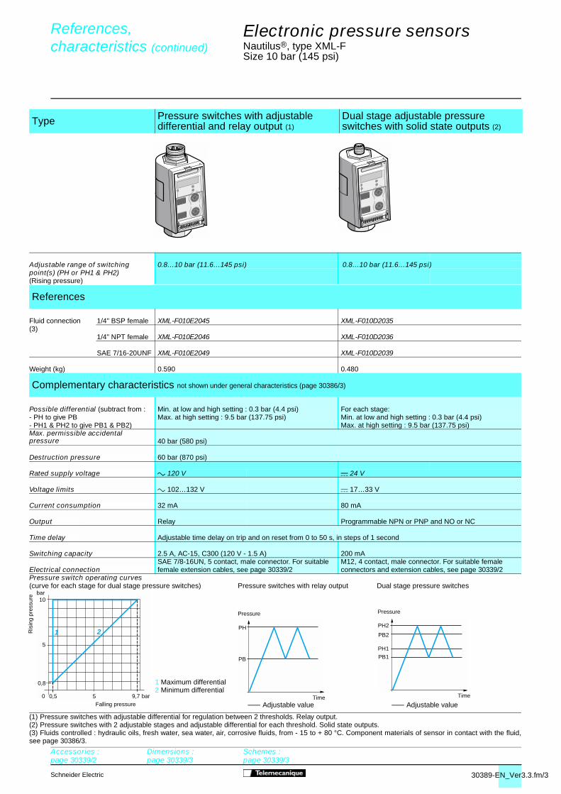
Pressure switch operating curves
(1) Pressure switches with adjustable differential for regulation between 2 thresholds. Relay output.(2) Pressure switches with 2 adjustable stages and adjustable differential for each threshold. Solid state outputs.(3) Fluids controlled : hydraulic oils, fresh water, sea water, air, corrosive fluids, from - 15 to + 80 °C. Component materials of sensor in contact with the fluid,see page 30386/3.
Type Pressure switches with adjustable differential and relay output (1)
Dual stage adjustable pressure switches with solid state outputs (2)
Adjustable range of switching 0.8…10 bar (11.6…145 psi) 0.8…10 bar (11.6…145 psi)point(s) (PH or PH1 & PH2)(Rising pressure)
References
Fluid connection 1/4" BSP female XML-F010E2045 XML-F010D2035(3)
1/4" NPT female XML-F010E2046 XML-F010D2036
SAE 7/16-20UNF XML-F010E2049 XML-F010D2039
Weight (kg) 0.590 0.480
Complementary characteristics not shown under general characteristics (page 30386/3)
Possible differential (subtract from : Min. at low and high setting : 0.3 bar (4.4 psi) For each stage:- PH to give PB Max. at high setting : 9.5 bar (137.75 psi) Min. at low and high setting : 0.3 bar (4.4 psi)- PH1 & PH2 to give PB1 & PB2) Max. at high setting : 9.5 bar (137.75 psi)Max. permissible accidental pressure 40 bar (580 psi)
Destruction pressure 60 bar (870 psi)
Rated supply voltage a 120 V c 24 V
Voltage limits a 102…132 V c 17…33 V
Current consumption 32 mA 80 mA
Output Relay Programmable NPN or PNP and NO or NC
Time delay Adjustable time delay on trip and on reset from 0 to 50 s, in steps of 1 second
Switching capacity 2.5 A, AC-15, C300 (120 V - 1.5 A) 200 mASAE 7/8-16UN, 5 contact, male connector. For suitable M12, 4 contact, male connector. For suitable female
Electrical connection female extension cables, see page 30339/2 connectors and extension cables, see page 30339/2
(curve for each stage for dual stage pressure switches) Pressure switches with relay output Dual stage pressure switches
References,characteristics (continued) 0
Accessories :page 30339/2
Dimensions :page 30339/3
Schemes :page 30339/3
� Adjustable value
� Adjustable value

30390-EN_Ver3.3.fm/2 Schneider Electric
PH
PB
1610 bar4 mA - 0 V
20 mA - 10 V
12 mA - 5 V
0 12 20 15,5
16
1,28
0,8 bar
10
bar
0 10
21
1 Maximum differential2 Minimum differential
Falling pressure
Ris
ing
pres
sure
Pressure
Time
Accessories :page 30339/2
Dimensions :page 30339/3
Schemes :page 30339/3
Electronic pressure sensors 4
Nautilus®, type XML-FSize 16 bar (232 psi)
(1) Pressure sensors with adjustable differential for regulation between 2 thresholds. Solid state output and analogue output.(2) Fluids controlled : hydraulic oils, fresh water, sea water, air, corrosive fluids, from - 15 to + 80 °C. Component materials of sensor in contact with the fluid,see page 30386/3.
Type Analogue sensors
Adjustable range of switching – 1.28…16 bar (18.56…232 psi) point (PH) (Rising pressure)
Analogue output 4-20 mA 0-10 V 4-20 mA 0-10 V
References
Fluid connection 1/4" BSP female XML-F016D2015 XML-F016D2115 XML-F016D2025 XML-F016D2125(2)
1/4" NPT female XML-F016D2016 XML-F016D2116 XML-F016D2026 XML-F016D2126
SAE 7/16-20UNF XML-F016D2019 XML-F016D2119 XML-F016D2029 XML-F016D2129
Weight (kg) 0.480 0.480 0.480 0.480
Complementary characteristics not shown under general characteristics (page 30386/3)
Possible differential – Min. at low and high setting: 0.48bar (6.96 psi) (subtract from PH to give PB) Max. at high setting: 15.2 bar (220.4 psi)Max. permissible accidental pressure 64 bar (928 psi)
Destruction pressure 96 bar (1392 psi)
Rated supply voltage c 24 V
Voltage limits c 17…33 V
Current consumption 80 mA 80 mA
Output – Programmable NPN or PNP and NO or NCAdjustable time delay on trip and on reset
Time delay – from 0 to 50 s, in steps of 1 second
Switching capacity – 200 mA
Analogue output 4…20 mA or 0…10 V, depending on model. Maximum signal level adjustable between 12 & 20 bar (174 & 290 psi)
Electrical connection M12, 4 contact, male connector. For suitable female connectors and extension cables, see page 30339/2Analogue output curve Pressure sensor operating curves
References,characteristics 0
Universal sensors with adjustable differ-ential. Solid state and analogue outputs (1)
� Adjustable value

30390-EN_Ver3.3.fm/3Schneider Electric
PH
PB
PH2
PH1
PB1
PB2
15,5
16
1,28
0,8 bar
10
bar
0 10
21
1 Maximum differential2 Minimum differential
Ris
ing
pres
sure
Falling pressure
Pressure
Time
Pressure
Time
Electronic pressure sensors 4
Nautilus®, type XML-FSize 16 bar (232 psi)
Pressure switch operating curves
(1) Pressure switches with adjustable differential for regulation between 2 thresholds. Relay output.(2) Pressure switches with 2 adjustable stages and adjustable differential for each threshold. Solid state outputs.(3) Fluids controlled : hydraulic oils, fresh water, sea water, air, corrosive fluids, from - 15 to + 80 °C. Component materials of sensor in contact with the fluid,see page 30386/3.
Type Pressure switches with adjustable differential and relay output (1)
Dual stage adjustable pressure switches with solid state outputs (2)
Adjustable range of switching 1.28…16 bar (18.56…232 psi) 1.28…16 bar (18.56…232 psi)point(s) (PH or PH1 & PH2)(Rising pressure)
References
Fluid connection 1/4" BSP female XML-F016E2045 XML-F016D2035(3)
1/4" NPT female XML-F016E2046 XML-F016D2036
SAE 7/16-20UNF XML-F016E2049 XML-F016D2039
Weight (kg) 0.590 0.480
Complementary characteristics not shown under general characteristics (page 30386/3)
Possible differential (subtract from : Min. at low and high setting: 0.48 bar (6.96 psi) For each stage:- PH to give PB Max. at high setting: 15.2 bar (220.4 psi) Min. at low and high setting: 0.48 bar (6.96 psi)- PH1 & PH2 to give PB1 & PB2) Max. at high setting: 15.2 bar (220.4 psi)Max. permissible accidental pressure 64 bar (928 psi)
Destruction pressure 96 bar (1392 psi)
Rated supply voltage a 120 V c 24 V
Voltage limits a 102…132 V c 17…33 V
Current consumption 32 mA 80 mA
Output Relay Programmable NPN or PNP and NO or NC
Time delay Adjustable time delay on trip and on reset from 0 to 50 s, in steps of 1 second
Switching capacity 2.5 A, AC-15, C300 (120 V - 1.5 A) 200 mASAE 7/8-16UN, 5 contact, male connector. For suitable M12, 4 contact, male connector. For suitable female
Electrical connection female extension cables, see page 30339/2 connectors and extension cables, see page 30339/2
(curve for each stage for dual stage pressure switches) Pressure switches with relay output Dual stage pressure switches
References,characteristics (continued) 0
Accessories :page 30339/2
Dimensions :page 30339/3
Schemes :page 30339/3
� Adjustable value
� Adjustable value

30391-EN_Ver3.3.fm/2 Schneider Electric
PH
PB
10 18,8 bar4 mA - 0 V
31,2
20 mA - 10 V
12 mA - 5 V
0 25
25
2
1,2 24,2 bar
10
bar
0 10
21
20
20
Ris
ing
pres
sure
1 Maximum differential2 Minimum differential
Falling pressure
Pressure
Time
Accessories :page 30339/2
Dimensions :page 30339/3
Schemes :page 30339/3
Electronic pressure sensors 4
Nautilus®, type XML-FSize 25 bar (362.5 psi)
(1) Pressure sensors with adjustable differential for regulation between 2 thresholds. Solid state output and analogue output.(2) Fluids controlled : hydraulic oils, fresh water, sea water, air, corrosive fluids, from - 15 to + 80 °C. Component materials of sensor in contact with the fluid,see page 30386/3.
Type Analogue sensors Universal sensors with adjustable differ-ential. Solid state and analogue outputs (1)
Adjustable range of switching – 2…25 bar (29…362.5 psi)point (PH) (Rising pressure)
Analogue output 4-20 mA 0-10 V 4-20 mA 0-10 V
References
Fluid connection 1/4" BSP female XML-F025D2015 XML-F025D2115 XML-F025D2025 XML-F025D2125(2)
1/4" NPT female XML-F025D2016 XML-F025D2116 XML-F025D2026 XML-F025D2126
SAE 7/16-20UNF XML-F025D2019 XML-F025D2119 XML-F025D2029 XML-F025D2129
Weight (kg) 0.480 0.480 0.480 0.480
Complementary characteristics not shown under general characteristics (page 30386/3)
Possible differential – Min. at low and high setting : 0.75 bar (10.9 psi) (subtract from PH to give PB) Max. at high setting : 23.8 bar (345.1 psi)Max. permissible accidental pressure 100 bar (1450 psi)
Destruction pressure 150 bar (2175 psi)
Rated supply voltage c 24 V
Voltage limits c 17…33 V
Current consumption 80 mA 80 mA
Output – Programmable NPN or PNP and NO or NCAdjustable time delay on trip and on reset
Time delay – from 0 to 50 s, in steps of 1 second
Switching capacity – 200 mA
Analogue output 4…20 mA or 0…10 V, depending on model. Maximum signal level adjustable between 18.8 & 31.2 bar (272.6 & 452.4 psi)
Electrical connection M12, 4 contact, male connector. For suitable female connectors and extension cables, see page 30339/2Analogue output curve Pressure sensor operating curves
References,characteristics 0
� Adjustable value

30391-EN_Ver3.3.fm/3Schneider Electric
PH
PB
PH2
PH1
PB1
PB2
25
2
1,2 24,2 bar
10
bar
0 10
21
20
20
1 Maximum differential2 Minimum differential
Ris
ing
pres
sure
Falling pressure
Accessories :page 30339/2
Dimensions :page 30339/3
Schemes :page 30339/3
Pressure
Time
Pressure
Time
Electronic pressure sensors 4
Nautilus®, type XML-FSize 25 bar (362.5 psi)
Pressure switch operating curves
(1) Pressure switches with adjustable differential for regulation between 2 thresholds. Relay output.(2) Pressure switches with 2 adjustable stages and adjustable differential for each threshold. Solid state outputs.(3) Fluids controlled : hydraulic oils, fresh water, sea water, air, corrosive fluids, from - 15 to + 80 °C. Component materials of sensor in contact with the fluid,see page 30386/3.
Type
Adjustable range of switching 2…25 bar (29…362.5 psi) 2…25 bar (29…362.5 psi)point(s) (PH or PH1 & PH2)(Rising pressure)
References
Fluid connection 1/4" BSP female XML-F025E2045 XML-F025D2035(3)
1/4" NPT female XML-F025E2046 XML-F025D2036
SAE 7/16-20UNF XML-F025E2049 XML-F025D2039
Weight (kg) 0.590 0.480
Complementary characteristics not shown under general characteristics (page 30386/3)
Possible differential (subtract from : Min. at low and high setting : 0.75 bar (10.9 psi) For each stage :- PH to give PB Max. at high setting : 23.8 bar (345.1 psi) Min. at low and high setting : 0.75 bar (10.9 psi)- PH1 & PH2 to give PB1 & PB2) Max. at high setting : 23.8 bar (345.1 psi)Max. permissible accidental pressure 100 bar (1450 psi)
Destruction pressure 150 bar (2175 psi)
Rated supply voltage a 120 V c 24 V
Voltage limits a 102…132 V c 17…33 V
Current consumption 32 mA 80 mA
Output Relay Programmable NPN or PNP and NO or NC
Time delay Adjustable time delay on trip and on reset from 0 to 50 s, in steps of 1 second
Switching capacity 2.5 A, AC-15, C300 (120 V - 1.5 A) 200 mASAE 7/8-16UN, 5 contact, male connector. For suitable M12, 4 contact, male connector. For suitable female
Electrical connection female extension cables, see page 30339/2 connectors and extension cables, see page 30339/2
(curve for each stage for dual stage pressure switches) Pressure switches with relay output Dual stage pressure switches
References,characteristics (continued) 0
Pressure switches with adjustable differential and relay output (1)
Dual stage adjustable pressure switcheswith solid state outputs (2)
� Adjustable value
� Adjustable value

30392-EN_Ver3.2.fm/2 Schneider Electric
PH
PB
10
30
10
40
3,2
2 38,8 bar
20
20
bar
0
1
30
2
10 20 30 bar4 mA - 0 V
40
20 mA - 10 V
12 mA - 5 V
0 50
Pressure
Falling pressure
1 Maximum differential2 Minimum differential
Ris
ing
pre
ssur
e
Time
Accessories :page 30339/2
Dimensions :page 30339/3
Schemes :page 30339/3
Electronic pressure sensors 4
Nautilus®, type XML-FSize 40 bar (580 psi)
(1) Pressure sensors with adjustable differential for regulation between 2 thresholds. Solid state output and analogue output.(2) Fluids controlled : hydraulic oils, fresh water, sea water, air, corrosive fluids, from - 15 to + 80 °C. Component materials of sensor in contact with the fluid,see page 30386/3.
Type Analogue sensorsUniversal sensors with adjustable differ-ential. Solid state and analogue outputs (1)
Adjustable range of switching – 3.2…40 bar (46.4…580 psi)point (PH) (Rising pressure)
Analogue output 4-20 mA 0-10 V 4-20 mA 0-10 V
References
Fluid connection 1/4" BSP female XML-F040D2015 XML-F040D2115 XML-F040D2025 XML-F040D2125(2)
1/4" NPT female XML-F040D2016 XML-F040D2116 XML-F040D2026 XML-F040D2126
SAE 7/16-20UNF XML-F040D2019 XML-F040D2119 XML-F040D2029 XML-F040D2129
Weight (kg) 0.500 0.500 0.500 0.500
Complementary characteristics not shown under general characteristics (page 30386/3)
Possible differential – Min. at low and high setting : 1.2 bar (17.4 psi) (subtract from PH to give PB) Max. at high setting : 38 bar (551 psi)Max. permissible accidental pressure 160 bar (2320 psi)
Destruction pressure 240 bar (3480 psi)
Rated supply voltage c 24 V
Voltage limits c 17…33 V
Current consumption 80 mA 80 mA
Output – Programmable NPN or PNP and NO or NCAdjustable time delay on trip and on reset
Time delay – from 0 to 50 s, in steps of 1 second
Switching capacity – 200 mA
Analogue output 4…20 mA or 0…10 V, depending on model. Maximum signal level adjustable between 30 & 50 bar (435 & 725 psi)
Electrical connection M12, 4 contact, male connector. For suitable female connectors and extension cables, see page 30339/2Analogue output curve Pressure sensor operating curves
References,characteristics 0
� Adjustable value

30392-EN_Ver3.2.fm/3Schneider Electric
PH
PB
PH2
PH1
PB1
PB2
10
30
10
40
3,2
2 38,8 bar
20
20
bar
0
1
30
2
1 Maximum differential2 Minimum differential
Ris
ing
pres
sure
Falling pressure
Accessories :page 30339/2
Dimensions :page 30339/3
Schemes :page 30339/3
Pressure
Time
Pressure
Time
Electronic pressure sensors 4
Nautilus®, type XML-FSize 40 bar (580 psi)
Pressure switch operating curves
(1) Pressure switches with adjustable differential for regulation between 2 thresholds. Relay output.(2) Pressure switches with 2 adjustable stages and adjustable differential for each threshold. Solid state outputs.(3) Fluids controlled : hydraulic oils, fresh water, sea water, air, corrosive fluids, from - 15 to + 80 °C. Component materials of sensor in contact with the fluid,see page 30386/3.
Type Pressure switches with adjustable differential and relay output (1)
Dual stage adjustable pressure switches with solid state outputs (2)
Adjustable range of switching 3.2…40 bar (46.4…580 psi) 3.2…40 bar (46.4…580 psi)point(s) (PH or PH1 & PH2)(Rising pressure)
References
Fluid connection 1/4" BSP female XML-F040E2045 XML-F040D2035(3)
1/4" NPT female XML-F040E2046 XML-F040D2036
SAE 7/16-20UNF XML-F040E2049 XML-F040D2039
Weight (kg) 0.610 0.500
Complementary characteristics not shown under general characteristics (page 30386/3)
Possible differential (subtract from : Min. at low and high setting : 1.2 bar (17.4 psi) For each stage :- PH to give PB Max. at high setting : 38 bar (551 psi) Min. at low and high setting : 1.2 bar (17.4 psi)- PH1 & PH2 to give PB1 & PB2) Max. at high setting : 38 bar (551 psi)Max. permissible accidental pressure 160 bar (2320 psi)
Destruction pressure 240 bar (3480 psi)
Rated supply voltage a 120 V c 24 V
Voltage limits a 102…132 V c 17…33 V
Current consumption 32 mA 80 mA
Output Relay Programmable NPN or PNP and NO or NC
Time delay Adjustable time delay on trip and on reset from 0 to 50 s, in steps of 1 second
Switching capacity 2.5 A, AC-15, C300 (120 V - 1.5 A) 200 mASAE 7/8-16UN, 5 contact, male connector. For suitable M12, 4 contact, male connector. For suitable female
Electrical connection female extension cables, see page 30339/2 connectors and extension cables, see page 30339/2
(curve for each stage for dual stage pressure switches) Pressure switches with relay output Dual stage pressure switches
References,characteristics (continued) 0
� Adjustable value
� Adjustable value

30393-EN_Ver3.3.fm/2 Schneider Electric
PH
PB
20 52,5 bar4 mA - 0 V
87,5
20 mA - 10 V
12 mA - 5 V
0 70
70
5,6
3,5 67,9 bar
50
bar
0 50
21
20
20
1 Maximum differential2 Minimum differential
Ris
ing
pres
sure
Pressure
Time � Adjustable value
Accessories :page 30339/2
Dimensions :page 30339/3
Schemes :page 30339/3
Electronic pressure sensors 4
Nautilus®, type XML-FSize 70 bar (1015 psi)
(1) Pressure sensors with adjustable differential for regulation between 2 thresholds. Solid state output and analogue output.(2) Fluids controlled : hydraulic oils, fresh water, sea water, air, corrosive fluids, from - 15 to + 80 °C. Component materials of sensor in contact with the fluid,see page 30386/3.
Type Analogue sensors Universal sensors with adjustable differ-ential. Solid state and analogue outputs (1)
Adjustable range of switching – 5.6…70 bar (81.2…1015 psi)point (PH) (Rising pressure)
Analogue output 4-20 mA 0-10 V 4-20 mA 0-10 V
References
Fluid connection 1/4" BSP female XML-F070D2015 XML-F070D2115 XML-F070D2025 XML-F070D2125(2)
1/4" NPT female XML-F070D2016 XML-F070D2116 XML-F070D2026 XML-F070D2126
SAE 7/16-20UNF XML-F070D2019 XML-F070D2119 XML-F070D2029 XML-F070D2129
Weight (kg) 0.500 0.500 0.500 0.500
Complementary characteristics not shown under general characteristics (page 30386/3)
Possible differential – Min. at low and high setting : 2.1 bar (30.5 psi) (subtract from PH to give PB) Max. at high setting : 66.5 bar (964.2 psi)Max. permissible accidental pressure 280 bar (4060 psi)
Destruction pressure 420 bar (6090 psi)
Rated supply voltage c 24 V
Voltage limits c 17…33 V
Current consumption 80 mA 80 mA
Output – Programmable NPN or PNP and NO or NCAdjustable time delay on trip and on reset
Time delay – from 0 to 50 s, in steps of 1 second
Switching capacity – 200 mA
Analogue output 4…20 mA or 0…10 V, depending on model. Maximum signal level adjustable between 52.5 & 87.5 bar (761.3 & 1268.7 psi)
Electrical connection M12, 4 contact, male connector. For suitable female connectors and extension cables, see page 30339/2Analogue output curve Pressure sensor operating curves
References,characteristics 0
Falling pressure

30393-EN_Ver3.3.fm/3Schneider Electric
PH
PB
PH2
PH1
PB1
PB2
70
5,6
3,5 67,9 bar
50
bar
0 50
21
20
20
1 Maximum differential2 Minimum differential
Ris
ing
pres
sure
Falling pressure
Accessories :page 30339/2
Dimensions :page 30339/3
Schemes :page 30339/3
� Adjustable value
Pressure
Time �
Adjustable value
Pressure
Time
Electronic pressure sensors 4
Nautilus®, type XML-FSize 70 bar (1015 psi)
Pressure switch operating curves
(1) Pressure switches with adjustable differential for regulation between 2 thresholds. Relay output.(2) Pressure switches with 2 adjustable stages and adjustable differential for each threshold. Solid state outputs.(3) Fluids controlled : hydraulic oils, fresh water, sea water, air, corrosive fluids, from - 15 to + 80 °C. Component materials of sensor in contact with the fluid,see page 30386/3.
Type Pressure switches with adjustabledifferential and relay output (1)
Dual stage adjustable pressure switches with solid state outputs (2)
Adjustable range of switching 5.6…70 bar (81.2…1015 psi) 5.6…70 bar (81.2…1015 psi)point(s) (PH or PH1 & PH2)(Rising pressure)
References
Fluid connection 1/4" BSP female XML-F070E2045 XML-F070D2035(3)
1/4" NPT female XML-F070E2046 XML-F070D2036
SAE 7/16-20UNF XML-F070E2049 XML-F070D2039
Weight (kg) 0.610 0.500
Complementary characteristics not shown under general characteristics (page 30386/3)
Possible differential (subtract from : Min. at low and high setting : 2.1 bar (30.5 psi) For each stage :- PH to give PB Max. at high setting : 66.5 bar (964.2 psi) Min. at low and high setting : 2.1 bar (30.5 psi)- PH1 & PH2 to give PB1 & PB2) Max. at high setting : 66.5 bar (964.2 psi)Max. permissible accidental pressure 280 bar (4060 psi)
Destruction pressure 420 bar (6090 psi)
Rated supply voltage a 120 V c 24 V
Voltage limits a 102…132 V c 17…33 V
Current consumption 32 mA 80 mA
Output Relay Programmable NPN or PNP and NO or NC
Time delay Adjustable time delay on trip and on reset from 0 to 50 s, in steps of 1 second
Switching capacity 2.5 A, AC-15, C300 (120 V - 1.5 A) 200 mASAE 7/8-16UN, 5 contact, male connector. For suitable M12, 4 contact, male connector. For suitable female
Electrical connection female extension cables, see page 30339/2 connectors and extension cables, see page 30339/2
(curve for each stage for dual stage pressure switches) Pressure switches with relay output Dual stage pressure switches
References,characteristics (continued) 0

30394-EN_Ver3.3.fm/2 Schneider Electric
PH
PB
75 bar4 mA - 0 V
50 125100
20 mA - 10 V
12 mA - 5 V
0
100
8
5 97 bar
50
bar
0 50
21
1 Maximum differential2 Minimum differential
Falling pressure
Ris
ing
pres
sure
Pressure
Time
Electronic pressure sensors 4
Nautilus®, type XML-FSize 100 bar (1450 psi)
(1) Pressure sensors with adjustable differential for regulation between 2 thresholds. Solid state output and analogue output.(2) Fluids controlled : hydraulic oils, fresh water, sea water, air, corrosive fluids, from - 15 to + 80 °C. Component materials of sensor in contact with the fluid,see page 30386/3.
Type Analogue sensors Universal sensors with adjustable differ-ential. Solid state and analogue outputs (1)
Adjustable range of switching – 8…100 bar (116…1450 psi)point (PH) (Rising pressure)
Analogue output 4-20 mA 0-10 V 4-20 mA 0-10 V
References
Fluid connection 1/4" BSP female XML-F100D2015 XML-F100D2115 XML-F100D2025 XML-F100D2125(2)
1/4" NPT female XML-F100D2016 XML-F100D2116 XML-F100D2026 XML-F100D2126
SAE 7/16-20UNF XML-F100D2019 XML-F100D2119 XML-F100D2029 XML-F100D2129
Weight (kg) 0.500 0.500 0.500 0.500
Complementary characteristics not shown under general characteristics (page 30386/3)
Possible differential (subtract from PH to give PB)
– Min. at low and high setting : 3 bar (43.5 psi) Max. at high setting : 95 bar (1377.5 psi)
Max. permissible accidental pressure 400 bar (5800 psi)
Destruction pressure 600 bar (8700 psi)
Rated supply voltage c 24 V
Voltage limits c 17…33 V
Current consumption 80 mA 80 mA
Output – Programmable NPN or PNP and NO or NCAdjustable time delay on trip and on reset
Time delay – from 0 to 50 s, in steps of 1 second
Switching capacity – 200 mA
Analogue output 4…20 mA or 0…10 V, depending on model. Maximum signal level adjustable between 75 & 125 bar (1087.5 & 1812.5 psi)
Electrical connection M12, 4 contact, male connector. For suitable female connectors and extension cables, see page 30339/2Analogue output curve Pressure sensor operating curves
References,characteristics 0
Accessories :page 30339/2
Dimensions :page 30339/3
Schemes :page 30339/3
Adjustable value

30394-EN_Ver3.3.fm/3Schneider Electric
PH
PB
PH2
PH1
PB1
PB2
100
8
5 97 bar
50
bar
0 50
21
Accessories :page 30339/2
Dimensions :page 30339/3
Schemes :page 30339/3
1 Maximum differential2 Minimum differential
Ris
ing
pres
sure
Falling pressure
Electronic pressure sensors 4
Nautilus®, type XML-FSize 100 bar (1450 psi)
Pressure switch operating curves
(1) Pressure switches with adjustable differential for regulation between 2 thresholds. Relay output.(2) Pressure switches with 2 adjustable stages and adjustable differential for each threshold. Solid state outputs.(3) Fluids controlled : hydraulic oils, fresh water, sea water, air, corrosive fluids, from - 15 to + 80 °C. Component materials of sensor in contact with the fluid,see page 30386/3.
Type Pressure switches with adjustable differential and relay output (1)
Dual stage adjustable pressure switches with solid state outputs (2)
Adjustable range of switching 8…100 bar (116…1450 psi) 8…100 bar (116…1450 psi)point(s) (PH or PH1 & PH2)(Rising pressure)
References
Fluid connection 1/4" BSP female XML-F100E2045 XML-F100D2035(3)
1/4" NPT female XML-F100E2046 XML-F100D2036
SAE 7/16-20UNF XML-F100E2049 XML-F100D2039
Weight (kg) 0,610 0.500
Complementary characteristics not shown under general characteristics (page 30386/3)
Possible differential (subtract from:- PH to give PB- PH1 & PH2 to give PB1 & PB2)
Min. at low and high setting : 3 bar (43.5 psi)Max. at high setting : 95 bar (1377.5 psi)
For each stage :Min. at low and high setting : 3 bar (43.5 psi)Max. at high setting : 95 bar (1377.5 psi)
Max. permissible accidental pressure 400 bar (5800 psi)
Destruction pressure 600 bar (8700 psi)
Rated supply voltage a 120 V c 24 V
Voltage limits a 102…132 V c 17…33 V
Current consumption 32 mA 80 mA
Output Relay Programmable NPN or PNP and NO or NC
Time delay Adjustable time delay on trip and on reset from 0 to 50 s, in steps of 1 second
Switching capacity 2,5 A, AC-15, C300 (120 V - 1,5 A) 200 mA
Electrical connectionSAE 7/8-16UN, 5 contact, male connector. For suitable female extension cables, see page 30339/2
M12, 4 contact, male connector. For suitable female connectors and extension cables, see page 30339/2.
(curve for each stage for dual stage pressure switches) Pressure switches with relay output Dual stage pressure switches
References,characteristics (continued) 0
0
Pressure
Time
Pressure
TimeAdjustable valueAdjustable value

30335-EN_Ver3.3.fm/2 Schneider Electric
PH
PB
160100 bar4 mA - 0 V
20 mA - 10 V
12 mA - 5 V
0 120 200 155,2
160
12,8
8 bar
100
0 100
21
Time
Pressure
Adjustable valueFalling pressure
1 Maximum differential2 Minimum differential
Electronic pressure sensors 4
Nautilus®, type XML-FSize 160 bar (2320 psi)
(1) Pressure sensors with adjustable differential for regulation between 2 thresholds. Solid state and analogue outputs.(2) Fluids controlled : hydraulic oils, fresh water, sea water, air, corrosive fluids, from - 15 to + 80 °C. Component materials of sensor in contact with the fluid,see page 30386/3.
Type Analogue sensors Universal sensors with adjustable differ-ential. Solid state and analogue outputs (1)
Adjustable range of switching – 12.8…160 bar (185.6…2320 psi)point (PH) (rising pressure)
Analogue output 4-20 mA 0-10 V 4-20 mA 0-10 V
References
Fluid connection 1/4" BSP female XML-F160D2015 XML-F160D2115 XML-F160D2025 XML-F160D2125(2)
1/4" NPT female XML-F160D2016 XML-F160D2116 XML-F160D2026 XML-F160D2126
SAE 7/16-20UNF XML-F160D2019 XML-F160D2119 XML-F160D2029 XML-F160D2129
Weight (kg) 0.590 0.590 0.590 0.590
Complementary characteristics not shown under general characteristics (page 30386/3)
Possible differential – Min. at low and high setting : 4.8 bar (69.6 psi) (subtract from PH to give PB) Max. at high setting : 152 bar (2204 psi)Max. permissible accidental pressure 640 bar (9280 psi)
Destruction pressure 960 bar (13,920 psi)
Rated supply voltage c 24 V
Voltage limits c 17…33 V
Current consumption 80 mA 80 mA
Output – Programmable NPN or PNP and NO or NCAdjustable time delay on trip and on reset
Time delay – from 0 to 50 s, in steps of 1 second
Switching capacity – 200 mA
Analogue output 4…20 mA or 0…10 V, depending on model. Maximum signal level adjustable between 120 & 200 bar (1740 & 2900 psi)
Electrical connection M12, 4 contact, male connector. For suitable female connectors and extension cables, see page 30339/2Analogue output curve Pressure sensor operating curves
References, characteristics 0
Accessories :page 30339/2
Dimensions :page 30339/3
Schemes :page 30339/3
Ris
ing
pres
sure
bar

30335-EN_Ver3.3.fm/3Schneider Electric
PH
PB
PH2
PH1
PB1
PB2
155,2
160
12,8
8 bar
100
bar
0 100
21
Falling pressure
Ris
ing
pres
sure
Adjustable value
Pressure
Time Adjustable value
Pressure
Time
1 Maximum differential2 Minimum differential
Accessories :page 30339/2
Dimensions :page 30339/3
Schemes :page 30339/3
Electronic pressure sensors 4
Nautilus®, type XML-FSize 160 bar (2320 psi)
Pressure switch operating curves
(1) Pressure switches with adjustable differential for regulation between 2 thresholds. Relay output.(2) Pressure switches with 2 adjustable stages and adjustable differential for each threshold. Solid state outputs.(3) Fluids controlled : hydraulic oils, fresh water, sea water, air, corrosive fluids, from - 15 to + 80 °C. Component materials of sensor in contact with the fluid,see page 30386/3.
Type Pressure switches with adjustabledifferential and relay output (1)
Dual stage adjustable pressure switcheswith solid state outputs (2)
Adjustable range of switching 12.8…160 bar (185.6…2320 psi) 12.8…160 bar (185.6…2320 psi)point(s) (PH or PH1 & PH2)(rising pressure)
References
Fluid connection 1/4" BSP female XML-F160E2045 XML-F160D2035(3)
1/4" NPT female XML-F160E2046 XML-F160D2036
SAE 7/16-20UNF XML-F160E2049 XML-F160D2039
Weight (kg) 0.700 0.590
Complementary characteristics not shown under general characteristics (page 30386/3)
Possible differential (subtract from : Min. at low and high setting : 4.8 bar (69.6 psi) For each stage :- PH to give PB Max. at high setting : 152 bar (2204 psi) min. at low and high setting : 4.8 bar (69.6 psi)- PH1 & PH2 to give PB1 & PB2) max. at high setting : 152 bar (2204 psi)Max. permissible accidental pressure 640 bar (9280 psi)
Destruction pressure 960 bar (13,920 psi)
Rated supply voltage a 120 V c 24 V
Voltage limits a 102…132 V c 17…33 V
Current consumption 32 mA 80 mA
Output Relay Programmable NPN or PNP and NO or NC
Time delay Adjustable time delay on trip and on reset from 0 to 50 s, in steps of 1 second
Switching capacity 2.5 A, AC-15, C300 (120 V - 1.5 A) 200 mASAE 7/8-16UN, 5 contact, male connector. For suitable M12, 4 contact, male connector. For suitable female
Electrical connection female extension cables, see page 30339/2 connectors and extension cables, see page 30339/2
(curve for each stage for dual stage pressure switches) Pressure switches with relay output Dual stage pressure switches
References, characteristics (continued) 0

30336-EN_Ver3.3.fm/2 Schneider Electric
PH
PB
100 187 bar4 mA - 0 V
312
20 mA - 10 V
12 mA - 5 V
0 250
250
20
12,5 242,5 bar
100
bar
0 100
21
200
200
Accessories :page 30339/2
Dimensions :page 30339/3
Schemes :page 30339/3
1 Maximum differential2 Minimum differential
Falling pressure
Pressure
Time Adjustable value
Electronic pressure sensors 4
Nautilus®, type XML-FSize 250 bar (3625 psi)
(1) Pressure sensors with adjustable differential for regulation between 2 thresholds. Solid state and analogue outputs.(2) Fluids controlled : hydraulic oils, fresh water, sea water, air, corrosive fluids, from - 15 to + 80 °C. Component materials of sensor in contact with the fluid,see page 30386/3.
Type Analogue sensors Universal sensors with adjustable differ-ential. Solid state and analogue outputs (1)
20…250 bar (290…3625 psi)Adjustable range of switching –point (PH) (rising pressure)
Analogue output 4-20 mA 0-10 V 4-20 mA 0-10 V
References
Fluid connection 1/4" BSP female XML-F250D2015 XML-F250D2115 XML-F250D2025 XML-F250D2125(2)
1/4" NPT female XML-F250D2016 XML-F250D2116 XML-F250D2026 XML-F250D2126
SAE 7/16-20UNF XML-F250D2019 XML-F250D2119 XML-F250D2029 XML-F250D2129
Weight (kg) 0.590 0.590 0.590 0.590
Complementary characteristics not shown under general characteristics (page 30386/3)
Possible differential – Min. at low and high setting : 7.5 bar (108.8 psi) (subtract from PH to give PB) Max. at high setting : 237.5 bar (3443.7 psi)Max. permissible accidental pressure 1000 bar (14,500 psi)
Destruction pressure 1500 bar (21,750 psi)
Rated supply voltage c 24 V
Voltage limits c 17…33 V
Current consumption 80 mA 80 mA
Output – Programmable NPN or PNP and NO or NCAdjustable time delay on trip and on reset
Time delay – from 0 to 50 s, in steps of 1 second
Switching capacity – 200 mA
Analogue output 4…20 mA or 0…10 V, depending on model. Maximum signal level adjustable between 187 & 312 bar (2711 & 4524 psi)
Electrical connection M12, 4 contact, male connector. For suitable female connectors and extension cables, see page 30339/2Analogue output curve Pressure sensor operating curves
References, characteristics 0
Ris
ing
pres
sure

30336-EN_Ver3.3.fm/3Schneider Electric
PH
PB
PH2
PH1
PB1
PB2
250
20
12,5 242,5 bar
100
bar
0 100
21
200
200
Ris
ing
pres
sure
Falling pressure
Time
Adjustable valueTime
Electronic pressure sensors 4
Nautilus®, type XML-FSize 250 bar (3625 psi)
Pressure switch operating curves
(1) Pressure switches with adjustable differential for regulation between 2 thresholds. Relay output.(2) Pressure switches with 2 adjustable stages and adjustable differential for each threshold. Solid state outputs.(3) Fluids controlled : hydraulic oils, fresh water, sea water, air, corrosive fluids, from - 15 to + 80 °C. Component materials of sensor in contact with the fluid,see page 30386/3.
Type Pressure switches with adjustable differential and relay output (1)
Dual stage adjustable pressure switches with solid state outputs (2)
Adjustable range of switching 20…250 bar (290…3625 psi) 20…250 bar (290…3625 psi)point(s) (PH or PH1 & PH2)(rising pressure)
References
Fluid connection 1/4" BSP female XML-F250E2045 XML-F250D2035(3)
1/4" NPT female XML-F250E2046 XML-F250D2036
SAE 7/16-20UNF XML-F250E2049 XML-F250D2039
Weight (kg) 0.700 0.590
Complementary characteristics not shown under general characteristics (page 30386/3)
Possible differential (subtract from : Min. at low and high setting : 7.5 bar (108.8 psi) For each stage :- PH to give PB Max. at high setting : 237.5 bar (3443.7 psi) min. at low and high setting : 7.5 bar (108.8 psi)- PH1 & PH2 to give PB1 & PB2) max. at high setting : 237.5 bar (3443.7 psi)Max. permissible accidental pressure 1000 bar (14,500 psi)
Destruction pressure 1500 bar (21,750 psi)
Rated supply voltage a 120 V c 24 V
Voltage limits a 102…132 V c 17…33 V
Current consumption 32 mA 80 mA
Output Relay Programmable NPN or PNP and NO or NC
Time delay Adjustable time delay on trip and on reset from 0 to 50 s, in steps of 1 second
Switching capacity 2.5 A, AC-15, C300 (120 V - 1.5 A) 200 mASAE 7/8-16UN, 5 contact, male connector. For suitable M12, 4 contact, male connector. For suitable female
Electrical connection female extension cables, see page 30339/2 connectors and extension cables, see page 30339/2
(curve for each stage for dual stage pressure switches) Pressure switches with relay output Dual stage pressure switches
Pressure Pressure
References, characteristics (continued) 0
Accessories :page 30339/2
Dimensions :page 30339/3
Schemes :page 30339/3
Adjustable value
1 Maximum differential2 Minimum differential

30337-EN_Ver3.3.fm/2 Schneider Electric
PH
PB
100 200 300 bar4 mA - 0 V
400
20 mA - 10 V
12 mA - 5 V
0 500
100
300
100
400
32
20 388 bar
200
200
bar
0
1
300
2
1 Maximum differential2 Minimum differential
Falling pressure
Ris
ing
pres
sure
Pressure
Time
Electronic pressure sensors 4
Nautilus®, type XML-FSize 400 bar (5800 psi)
(1) Pressure sensors with adjustable differential for regulation between 2 thresholds. Solid state and analogue outputs.(2) Fluids controlled : hydraulic oils, fresh water, sea water, air, corrosive fluids, from - 15 to + 80 °C. Component materials of sensor in contact with the fluid,see page 30386/3.
Type Analogue sensors Universal sensors with adjustable differ-ential. Solid state and analogue outputs (1)
Adjustable range of switching – 32…400 bar (464…5800 psi) point (PH) (rising pressure)
Analogue output 4-20 mA 0-10 V 4-20 mA 0-10 V
References
Fluid connection 1/4" BSP female XML-F400D2015 XML-F400D2115 XML-F400D2025 XML-F400D2125(2)
1/4" NPT female XML-F400D2016 XML-F400D2116 XML-F400D2026 XML-F400D2126
SAE 7/16-20UNF XML-F400D2019 XML-F400D2119 XML-F400D2029 XML-F400D2129
Weight (kg) 0.590 0.590 0.590 0.590
Complementary characteristics not shown under general characteristics (page 30386/3)
Possible differential – Min. at low and high setting : 12 bar (174 psi) (subtract from PH to give PB) Max. at high setting : 380 bar (5510 psi)Max. permissible accidental pressure 1200 bar (17,400 psi)
Destruction pressure 1800 bar (26,100 psi)
Rated supply voltage c 24 V
Voltage limits c 17…33 V
Current consumption 80 mA 80 mA
Output – Programmable NPN or PNP and NO or NCAdjustable time delay on trip and on reset
Time delay – from 0 to 50 s, in steps of 1 second
Switching capacity – 200 mA
Analogue output 4…20 mA or 0…10 V, depending on model. Maximum signal level adjustable between 300 & 500 bar (4350 & 7250 psi)
Electrical connection M12, 4 contact, male connector. For suitable female connectors and extension cables, see page 30339/2Analogue output curve Pressure sensor operating curves
References, characteristics 0
Accessories :page 30339/2
Dimensions :page 30339/3
Schemes :page 30339/3
� Adjustable value

30337-EN_Ver3.3.fm/3Schneider Electric
PH
PB
PH2
PH1
PB1
PB2
100
300
100
400
32
20 388 bar
200
200
bar
0
1
300
2
1 Maximum differential2 Minimum differential
Ris
ing
pres
sure
Falling pressure
Pressure
Time
Pressure
Time
Electronic pressure sensors 4
Nautilus®, type XML-FSize 400 bar (5800 psi)
Pressure switch operating curves
(1) Pressure switches with adjustable differential for regulation between 2 thresholds. Relay output.(2) Pressure switches with 2 adjustable stages and adjustable differential for each threshold. Solid state outputs.(3) Fluids controlled : hydraulic oils, fresh water, sea water, air, corrosive fluids, from - 15 to + 80 °C. Component materials of sensor in contact with the fluid,see page 30386/3.
Type
Adjustable range of switching 32…400 bar (464…5800 psi) 32…400 bar (464…5800 psi)point(s) (PH or PH1 & PH2)(rising pressure)
References
Fluid connection 1/4" BSP female XML-F400E2045 XML-F400D2035(3)
1/4" NPT female XML-F400E2046 XML-F400D2036
SAE 7/16-20UNF XML-F400E2049 XML-F400D2039
Weight (kg) 0.700 0.590
Complementary characteristics not shown under general characteristics (page 30386/3)
Possible differential (subtract from : Min. at low and high setting : 12 bar (174 psi) For each stage :- PH to give PB Max. at high setting : 380 bar (5510 psi) min. at low and high setting : 12 bar (174 psi)- PH1 & PH2 to give PB1 & PB2) max. at high setting : 380 bar (5510 psi)Max. permissible accidental pressure 1200 bar (17,400 psi)
Destruction pressure 1800 bar (26,100 psi)
Rated supply voltage a 120 V c 24 V
Voltage limits a 102…132 V c 17…33 V
Current consumption 32 mA 80 mA
Output Relay Programmable NPN or PNP and NO or NC
Time delay Adjustable time delay on trip and on reset from 0 to 50 s, in steps of 1 second
Switching capacity 2.5 A, AC-15, C300 (120 V - 1.5 A) 200 mASAE 7/8-16UN, 5 contact, male connector. For suitable M12, 4 contact, male connector. For suitable female
Electrical connection female extension cables, see page 30339/2 connectors and extension cables, see page 30339/2
(curve for each stage for dual stage pressure switches) Pressure switches with relay output Dual stage pressure switches
References, characteristics (continued) 0
Pressure switches with adjustable differential and relay output (1)
Dual stage adjustable pressure switches with solid state outputs (2)
Accessories :page 30339/2
Dimensions :page 30339/3
Schemes :page 30339/3
� Adjustable value
� Adjustable value

30338-EN_Ver3.3.fm/2 Schneider Electric
PH
PB
200 450 bar4 mA - 0 V
750
20 mA - 10 V
12 mA - 5 V
0 600
600
48
30 582 bar
200
bar
0 400
21400
200
1 Maximum differential2 Minimum differential
Falling pressure
Ris
ing
pres
sure
Pressure
Time
Accessories :page 30339/2
Dimensions :page 30339/3
Schemes :page 30339/3
Electronic pressure sensors 4
Nautilus®, type XML-FSize 600 bar (8700 psi)
(1) Pressure sensors with adjustable differential for regulation between 2 thresholds. Solid state and analogue outputs.(2) Fluids controlled : hydraulic oils, fresh water, sea water, air, corrosive fluids, from - 15 to + 80 °C. Component materials of sensor in contact with the fluid,see page 30386/3.
Type Analogue sensors Universal sensors with adjustable differ-ential. Solid state and analogue outputs (1)
Adjustable range of switching – 48…600 bar (696…8700 psi)point (PH) (rising pressure)
Analogue output 4-20 mA 0-10 V 4-20 mA 0-10 V
References
Fluid connection 1/4" BSP female XML-F600D2015 XML-F600D2115 XML-F600D2025 XML-F600D2125(2)
1/4" NPT female XML-F600D2016 XML-F600D2116 XML-F600D2026 XML-F600D2126
SAE 7/16-20UNF XML-F600D2019 XML-F600D2119 XML-F600D2029 XML-F600D2129
Weight (kg) 0.590 0.590 0.590 0.590
Complementary characteristics not shown under general characteristics (page 30386/3)
Possible differential – Min. at low and high setting : 18 bar (261 psi) (subtract from PH to give PB) Max. at high setting : 570 bar (8265 psi)Max. permissible accidental pressure 1200 bar (17,400 psi)
Destruction pressure 1800 bar (26,100 psi)
Rated supply voltage c 24 V
Voltage limits c 17…33 V
Current consumption 80 mA 80 mA
Output – Programmable NPN or PNP and NO or NCAdjustable time delay on trip and on reset
Time delay – from 0 to 50 s, in steps of 1 second
Switching capacity – 200 mA
Analogue output 4…20 mA or 0…10 V, depending on model. Maximum signal level adjustable between 450 & 750 bar (6525 & 10,875 psi)
Electrical connection M12, 4 contact, male connector. For suitable female connectors and extension cables, see page 30339/2Analogue output curve Pressure sensor operating curves
References, characteristics 0
� Adjustable value

30338-EN_Ver3.3.fm/3Schneider Electric
PH
PB
PH2
PH1
PB1
PB2
600
48
30 582 bar
200
bar
0 400
21400
200
1 Maximum differential2 Minimum differential
Ris
ing
pres
sure
Falling pressure
Pressure
Time
Pressure
Time
Electronic pressure sensors 4
Nautilus®, type XML-FSize 600 bar (8700 psi)
Pressure switch operating curves
(1) Pressure switches with adjustable differential for regulation between 2 thresholds. Relay output.(2) Pressure switches with 2 adjustable stages and adjustable differential for each threshold. Solid state outputs.(3) Fluids controlled : hydraulic oils, fresh water, sea water, air, corrosive fluids, from - 15 to + 80 °C. Component materials of sensor in contact with the fluid,see page 30386/3.
Type Pressure switches with adjustable differential and output relay (1)
Dual stage adjustable pressure switches with solid state outputs (2)
Adjustable range of switching 48…600 bar (696…8700 psi) 48…600 bar (696…8700 psi)point(s) (PH or PH1 & PH2)(rising pressure)
References
Fluid connection 1/4" BSP female XML-F600E2045 XML-F600D2035(3)
1/4" NPT female XML-F600E2046 XML-F600D2036
SAE 7/16-20UNF XML-F600E2049 XML-F600D2039
Weight (kg) 0.700 0.590
Complementary characteristics not shown under general characteristics (page 30386/3)
Possible differential (subtract from : Min. at low and high setting : 18 bar (261 psi) For each stage :- PH to give PB Max. at high setting : 570 bar (8265 psi) min. at low and high setting : 18 bar (261 psi)- PH1 & PH2 to give PB1 & PB2) max. at high setting : 570 bar (8265 psi)Max. permissible accidental pressure 1200 bar (17,400 psi)
Destruction pressure 1800 bar (26,100 psi)
Rated supply voltage a 120 V c 24 V
Voltage limits a 102…132 V c 17…33 V
Current consumption 32 mA 80 mA
Output Relay Programmable NPN or PNP and NO or NC
Time delay Adjustable time delay on trip and on reset from 0 to 50 s, in steps of 1 second
Switching capacity 2.5 A, AC-15, C300 (120 V - 1.5 A) 200 mASAE 7/8-16UN, 5 contact, male connector. For suitable M12, 4 contact, male connector. For suitable female
Electrical connection female extension cables, see page 30339/2 connectors and extension cables, see page 30339/2
(curve for each stage for dual stage pressure switches) Pressure switches with relay output Dual stage pressure switches
References, characteristics (continued) 0
Accessories :page 30339/2
Dimensions :page 30339/3
Schemes :page 30339/3
� Adjustable value
� Adjustable value

30339-EN_Ver6.2.fm/2 Schneider Electric
References 4 Electronic pressure sensors 4
Nautilus® Universal Osiconcept®, type XML FAccessories and replacement parts
Replacement partsDescription Reference Weight
kgTransparent cover with legends XML ZL007 0.020
Sealing gasket All sizes (XML F) XML ZL010 0.015
AccessoriesDescription Length of
cableReference Weight
kgFixing bracket – XML ZL008 0.037
Cooler for versions with1/4" BSP fluid connection (2)Usage temperature : 150 °C max. for the fluid, 50 °C for the ambient air
– XML ZL009 0.370
Pre-wired M12, straight, female connectors
2 m XZ CP1141L2 0.115
5 m XZ CP1141L5 0.27010 m XZ CP1141L10 0.520
Pre-wired M12, elbowed, female connectors
2 m XZ CP1241L2 0.1155 m XZ CP1241L5 0.27010 m XZ CP1241L10 0.520
Pre-wired 7/8" 16UN, straight, female connectors
2 m XZ CP1764L2 0.185
5 m XZ CP1764L5 0.46010 m XZ CP1764L10 0.900
M12 “Snap-C”, straight, female connector (1)
– XZ CC12FDM40V 0.520
M12-M12 jumper cableswith straight male connector, for splitter box
Straight female connector
1 m XZ CR1511041C1 0.065
2 m XZ CR1511041C2 0.095
Elbowed female connector
1 m XZ CR1512041C1 0.0652 m XZ CR1512041C2 0.095
(1) Connector incorporating IDCs (Insulation Displacement Connectors) for simple and quick direct, in-line, connection to cable, without the need of a screwdriver or soldering iron.
(2) Available with other hydraulic connections : 1/4" NPT and SAE 7/16 20 UNF.
XML ZL007
XZ CP1141Lp XZ CP1241Lp
XZ CP1764Lp XZ CC12FDM40V
XZ CR1511041Cp XZ CR1512041Cp
XML ZL010 XML ZL008XML ZL009
XML ZL010

30339-EN_Ver6.2.fm/3Schneider Electric
Dimensions, schemes 4
Electronic pressure sensors 4
Nautilus® Universal Osiconcept®, type XML FAccessories and replacement parts
DimensionsXML ZL009 XML FpppD2ppp
(1) Female fluid entryXML FpppD2pp5 : G 1/4 AXML FpppD2pp6 : 1/4" NPTXML FpppD2pp9 : SAE 7/16 20UNF
XML ZL008
XML FpppE2ppp
(1) Female fluid entryXML FpppE2pp5 : G 1/4 AXML FpppE2pp6 : 1/4" NPTXML FpppE2pp9 : SAE 7/16 20UNF
XML ZL010
Connector schemes (pressure sensor connector pin view)XML FpppD201p, FpppD211p
XML FpppD202p, FpppD212p
XML FpppD203p XML FpppE204p
G1/
4
G1/
4
1627
114
138
8815
129 14
2
113
10
58 46
27(1)
M12 x 1
Ø4,4
58
17
49,6
20
4,2
10
12,45
Ø31,2
21
9,63
138
8815
164
119
16
58 46
27(1)
7/8" 16 UN
Ø14 2
1,5
Ø19
1 2
4 3
+
–Calibration shunt
Analogue output
1 2
4 3
+
–Solid state output
Analogue output
1 2
4 3
+
–1st stage solid state output
Analogue output
43
2
5 1Relay output

30365-EN_Ver4.3.fm/2 Schneider Electric
����������������������������
����������������������������
�������������
���������������������
��������
�������
5
1
2
3
4
7
6
2
Presentation, principle 0
Electronic pressure sensors 4
Nautilus® type XML-E
XML-E pressure switches and analogue pressure sensors are characterised by their use of ceramic technologymeasuring load cells.
1 Threaded fluid entry
2 Sealing gaskets
3 Measuring load cell (ceramic technology)
4 Electronic card
5 Electrical connector
6 Adjustment potentiometer for switching point PH
7 Adjustment potentiometer for switching point PB
XML-E pressure switches incorporate a solid state NPN or PNP N/C output.Two potentiometers enable the setting of the PH (rising pressure) and PB (falling pressure) switching points.
XML-E analogue pressure sensors provide a 4 to 20 mA analogue output which is proportional to the measuring range.
A digital display unit can be directly plugged-in between themale and female DIN 43650A connectors.The display may be adjusted to enable reading from anydirection (360° orientation both vertically and horizontally).Simple unrestricted positioning of the display unit + sensor+ connector (can be rotated through 360°).
Presentation
(rising pressure).Only applicable to pressure switches
(falling pressure).Only applicable to pressure switches
Operating principle

30365-EN_Ver4.3.fm/3Schneider Electric
Electronic pressure sensors 4
Nautilus® type XML-E
Environment characteristics
Conforming to standards e, EN 50081, EN 50082
Product certifications UL, CSA
Protective treatment Standard version “TC”
Ambient air temperature °C Operation : - 15…+ 80
Fluids or products controlled Hydraulic oils, air, fresh water, sea water, corrosive fluids : - 15…+ 80 °C
Component materials of switch in contact with fluid
Stainless steel fluid entry type AISI 303, viton gasket
Operating position All positions
Vibration resistance 5 gn (25…200 Hz) and 35 gn (60…2000 Hz)
Shock resistance 50 gn
Electrical protection Protected against reverse polarity, short-circuit and overload
Degree of protection IP 65 conforming to IEC/EN 60529
Operating rate Hz 50
Response time ms < 5
Service life Oper. > 10 millioncycles
Drift Of the zero point : < ± 0.05 % of the measuring range/°COf the sensitivity : < ± 0.015 % of the measuring range/°C
Precision < ± 0.5 % of the measuring range
Fluid connections G 1/4 A (BSP male) conforming to NF E 03-004, ISO 7
Electrical connections DIN 43650A or M12 connector
Characteristics 0

30366-EN_Ver5.3.fm/2 Schneider Electric
Electronic pressure sensors 4
Nautilus®, type XML-E Sensors without display (1)
Sizes - 1 to 25 bar (- 14.5 to 362.5 psi)
Output curves
Units With analogue output, fluid connection 1/4" BSP male
Pressure range 0…- 1 bar (0…- 14.5 psi) 0…1 bar (0…14.5 psi)
Electrical connector type DIN 43650A M12 DIN 43650A M12
References
Fluids controlled (2)
Hydraulic oils, fresh water, XML-EM01U1C21 XML-EM01U1D21 XML-E001U1C21 XML-E001U1D21sea water, air, corrosive fluids,from - 15 to + 80 °C
Weight (kg) 0,250 0,300 0,250 0,300
Complementary characteristics not shown under general characteristics (page 30365/3)
Max. permissible accidental pressure 1 bar (14.5 psi) 2 bar (29 psi)
Destruction pressure 2 bar (29 psi) 3 bar (43.5 psi)
Rated supply voltage c 24 V
Voltage limits c 11…33 V
Output Analogue, 4…20 mA. 2-wire type
Current consumption < 20 mA
Electrical connection XML-EpppU1C21 : DIN 43650A, 4-pin male connector. For suitable female connector, see page 30368/2XML-EpppU1D21 : M12, 5-pin male connector. For suitable extension cables, see page 30368/2
(1) Optional digital display for sensor, see page 30368/2.(2) Component materials of sensor in contact with the fluid, see page 30365/3.
Other versions Analogue pressure sensors with fluid connection 1/4" NPTF.Please consult your Regional Sales Office.
8116
39
8116
38
8116
45
8116
38
Is (mA)
-1 0 P (bar)-0,8 -0,2-0,4-0,6
20
16
12
8
4
8116
37
0,2 0,80,60,4
Is (mA)20
16
8
12
40 1 P (bar)
8116
36
References, characteristics 0
Accessories :page 30368/2
Dimensions :page 30368/3
Schemes :page 30368/3

30366-EN_Ver5.3.fm/3Schneider Electric
4
.
With analogue output, fluid connection 1/4" BSP male
0…10 bar (0…145 psi) 0…25 bar (0…362.5 psi)
DIN 43650A M12 DIN 43650A M12
XML-E010U1C21 XML-E010U1D21 XML-E025U1C21 XML-E025U1D21
0.250 0.300 0.250 0.300
20 bar (290 psi) 50 bar (725 psi)
30 bar (435 psi) 75 bar (1087.5 psi)
c 24 V
c 11…33 V
Analogue, 4…20 mA. 2-wire type
< 20 mA
XML-EpppU1C21 : DIN 43650A, 4-pin male connector. For suitable female connector, see page 30368/2XML-EpppU1D21 : M12, 5-pin male connector. For suitable extension cables, see page 30368/2
8116
39
8116
44
8116
45
8116
44
2 864
Is (mA)20
16
8
12
40 10 P (bar)
8116
41
5 201510
Is (mA)20
16
8
12
40 25 P (bar)
8116
40
0

30366-EN_Ver5.3.fm/4 Schneider Electric
Electronic pressure sensors 4
Nautilus®, type XML-E Sensors without display (1)
Sizes 60 to 600 bar (870 to 8700 psi)
Output curves
Units With analogue output, fluid connection 1/4" BSP male
Pressure range 0…60 bar (0…870 psi) 0…100 bar (0…1450 psi)
Electrical connector type DIN 43650A M12 DIN 43650A M12
References
Fluids controlled (2)
Hydraulic oils, fresh water, XML-E060U1C21 XML-E060U1D21 XML-E100U1C21 XML-E100U1D21sea water, air, corrosive fluids,from - 15 to + 80 °C
Weight (kg) 0.270 0.320 0.270 0.320
Complementary characteristics not shown under general characteristics (page 30365/3)
Max. permissible accidental pressure 120 bar (1740 psi) 200 bar (2900 psi)
Destruction pressure 180 bar (2610 psi) 300 bar (4350 psi)
Rated supply voltage c 24 V
Voltage limits c 11…33 V
Output Analogue, 4…20 mA. 2-wire type
Current consumption < 20 mA
Electrical connection XML-EpppU1C21 : DIN 43650A, 4-pin male connector. For suitable female connector, see page 30368/2XML-EpppU1D21 : M12, 5-pin male connector. For suitable extension cables, see page 30368/2
(1) Optional digital display for sensor, see page 30368/2.(2) Component materials of sensor in contact with the fluid, see page 30365/3.
Other versions Analogue pressure sensors with fluid connection 1/4" NPTF.Please consult your Regional Sales Office.
8116
39
8116
38
8116
45
8116
44
10 4030 5020
Is (mA)20
16
8
12
40 60 P (bar)
8116
43
20 806040
Is (mA)20
16
8
12
40 100 P (bar)
8116
42
References, characteristics (continued) 0
Accessories :page 30368/2
Dimensions :page 30368/3
Schemes :page 30368/3

30366-EN_Ver5.3.fm/5Schneider Electric
4
.
With analogue output, fluid connection 1/4" BSP male
0…250 bar (0…3625 psi) 0…600 bar (0…8700 psi)
DIN 43650A M12 DIN 43650A M12
XML-E250U1C21 XML-E250U1D21 XML-E600U1C21 XML-E600U1D21
0.270 0.320 0.270 0.320
500 bar (7250 psi) 1200 bar (17.400 psi)
750 bar (10.875 psi) 1800 bar (26.100 psi)
c 24 V
c 11…33 V
Analogue, 4…20 mA. 2-wire type
< 20 mA
XML-EpppU1C21 : DIN 43650A, 4-pin male connector. For suitable female connector, see page 30368/2XML-EpppU1D21 : M12, 5-pin male connector. For suitable extension cables, see page 30368/2
8116
39
8116
38
8116
45
8116
44
50 200150100
Is (mA)20
16
8
12
40 250P (bar)
8116
47
100 400300 500200
Is (mA)20
16
8
12
40 600 P (bar)
8116
46
00

30367-EN_Ver6.3.fm/2 Schneider Electric
8116
50
8116
49
8116
57
8116
56
0bar
bar0 -0,2-0,05
-0,4 -0,6 -0,8-0,98
-0,2
-0,07
-0,4
-0,6
-0,8
-1
1 2
bar
bar0 0,20,05
0,4 0,6 0,80,98
0,07
1
1 2
0,8
0,6
0,4
0,2
0
References, characteristics 0
Accessories :page 30368/2
Dimensions :page 30368/3
Schemes :page 30368/3
Rising pressure
1 Maximum differential2 Minimum differential
Ris
ing
pres
sure
Falling pressure
Fal
ling
pres
sure
Electronic pressure sensors 4
Nautilus®, type XML-EVacuum and pressure switches without display (1), with adjustable differential, for regulation between two thresholdsSizes -1 to 25 bar (-14.5 to 362.5 psi)
.
Units With solid state output, fluid connection 1/4" BSP male
Adjustable range of switchingpoint (PH) (rising pressure) (2) -0.07...-1 bar (-1.015...-14.5 psi) 0.07...1 bar (1.015...14.5 psi)
Electrical connector type DIN 43650A M12 DIN 43650A M12
References
Type ofFluids controlled (3) output
Hydraulic oils, fresh water, NPN XML-EM01U1C31 XML-EM01U1D31 XML-E001U1C31 XML-E001U1D31sea water, air, corrosive fluids,from - 15 to +80°C PNP XML-EM01U1C41 XML-EM01U1D41 XML-E001U1C41 XML-E001U1D41
Weight (kg) 0.250 0.300 0.250 0.300
Complementary characteristics not shown under general characteristics (page 30365/3)
Possible Min. at low setting 0.02 bar (0.29 psi) 0.02 bar (0.29 psi)differential
Min. at high setting 0.02 bar (0.29 psi) 0.02 bar (0.29 psi)
Max. at high setting 0.95 bar (13.77 psi) (max. differential at low setting) 0.95 bar (13.77 psi)
Max. permissible accidental pressure 1 bar (14.5 psi) 2 bar (29 psi)
Destruction pressure 2 bar (29 psi) 3 bar (43.5 psi)
Rated supply voltage c 24 V
Voltage limits c 11...33 V
Output Solid state, NPN or PNP, N/CSwitching capacity 100 mACurrent consumption < 15 mAElectrical connection XML-EpppU1Cp1 : DIN 43650A, 4-pin male connector. For suitable female connector, see page 30368/2
XML-EpppU1Dp1 : M12, 5-pin male connector. For suitable extension cables, see page 30368/2Operating curves
(1) Optional digital display for sensor, see page 30368/2.(2) For vacuum switches (size - 1 bar) : operating range of switching point (PB), falling pressure.(3) Component materials of sensor in contact with the fluid, see page 30365/3.
Other versions Pressure and vacuum switches with fluid connection 1/4" NPTFPlease consult your Regional Sales Office.

30367-EN_Ver6.3.fm/3Schneider Electric
81
1650
8116
49
8116
57
8116
56
bar
bar0 20,5
4 6 89,8
0,7
10
8
6
4
2
0
21
bar
bar0 51,25
10 15 2024,5
1,75
5
25
10
15
20
0
21Ris
ing
pres
sure
Falling pressure Falling pressure
Ris
ing
pres
sur e
4
With solid state output, fluid connection 1/4" BSP male
0.7…10 bar (10.15…145 psi) 1.75…25 bar (25.38…362.5 psi)
DIN 43650A M12 DIN 43650A M12
XML-E010U1C31 XML-E010U1D31 XML-E025U1C31 XML-E025U1D31
XML-E010U1C41 XML-E010U1D41 XML-E025U1C41 XML-E025U1D41
0.250 0.300 0.250 0.300
0.2 bar (2.9 psi) 0.5 bar (7.25 psi)
0.2 bar (2.9 psi) 0.5 bar (7.25 psi)
9.5 bar (137.7 psi) 23.75 bar (344.37psi)
20 bar (290 psi) 50 bar (725 psi)
30 bar (435 psi) 75 bar (1087.5 psi)
c 24 V
c 11…33 V
Solid state, NPN or PNP, N/C100 mA< 15 mAXML-EpppU1Cp1 : DIN 43650A, 4-pin male connector. For suitable female connectors, see page 30368/2XML-EpppU1Dp1 : M12, 5-pin male connector. For suitable extension cables, see page 30368/2
0

30367-EN_Ver6.3.fm/4 Schneider Electric
8116
50
8116
49
8116
57
8116
56
bar
bar0 50403020103 58,8
4,2
10
20
30
40
50
60
0
1 2
bar
bar0 205
40 60 8098
7
20
100
40
60
80
0
1 2
Electronic pressure sensors 4
Nautilus®, type XML-EPressure switches without display (1), with adjustable differential, for regulation between two thresholdsSizes 60 to 600 bar (870 to 8700 psi).
Operating curves
Units With solid state output, fluid connection 1/4" BSP male
Adjustable range of switchingpoint (PH) (rising pressure) (2) 4.2…60 bar (60.9…870 psi) 7…100 bar (101.5…1450 psi)
Electrical connector type DIN 43650A M12 DIN 43650A M12
References
Type ofFluids controlled (3) output
Hydraulic oils, fresh water, NPN XML-E060U1C31 XML-E060U1D31 XML-E100U1C31 XML-E100U1D31sea water, air, corrosive fluids,from - 15 to + 80 °C PNP XML-E060U1C41 XML-E060U1D41 XML-E100U1C41 XML-E100U1D41
Weight (kg) 0.270 0.320 0.270 0.320
Complementary characteristics not shown under general characteristics (page 30365/3)
Possible Min. at low setting 1.2 bar (17.4 psi) 2 bar (29 psi)differential
Min. at high setting 1.2 bar (17.4 psi) 2 bar (29 psi)
Max. at high setting 57 bar (826.5 psi) 95 bar (1377.5 psi)
Max. permissible accidental pressure 120 bar (1740 psi) 200 bar (2900 psi)
Destruction pressure 180 bar (2610 psi) 300 bar (4350 psi)
Rated supply voltage c 24 V
Voltage limits c 11…33 V
Output Solid state, NPN or PNP, N/CSwitching capacity 100 mACurrent consumption < 15 mAElectrical connection XML-EpppU1Cp1 : DIN 43650A, 4-pin male connector. For suitable female connector, see page 30368/2
XML-EpppU1Dp1 : M12, 5-pin male connector. For suitable extension cables, see page 30368/2
(1) Optional digital display for sensor, see page 30368/2.(2) For vacuum switches (size - 1 bar) : operating range of switching point (PB), falling pressure.(3) Component materials of sensor in contact with the fluid, see page 30365/3.
Other versions Pressure and vacuum switches with fluid connection 1/4" NPTF.Please consult your Regional Sales Office.
References, characteristics (continued) 0
Accessories :page 30368/2
Dimensions :page 30368/3
Schemes :page 30368/3
Ris
ing
pres
sure
Falling pressure
1 Maximum differential2 Minimum differential
Ris
ing
pres
sure
Falling pressure

30367-EN_Ver6.3.fm/5Schneider Electric
81
1650
8116
49
8116
57
8116
56
bar
17,5
50
250
100
150
200
0
1 2
bar0 5012,5
100 150 200245
bar
bar0 50040030020010030 588
42
100
200
300
400
500
600
0
1 2
Ris
ing
pres
sure
Falling pressure
Ris
ing
pres
sure
Falling pressure
4
With solid state output, fluid connection 1/4" BSP male
17.5…250 bar (253.7…3625 psi) 42…600 bar (609…8700 psi)
DIN 43650A M12 DIN 43650A M12
XML-E250U1C31 XML-E250U1D31 XML-E600U1C31 XML-E600U1D31
XML-E250U1C41 XML-E250U1D41 XML-E600U1C41 XML-E600U1D41
0.270 0.320 0.270 0.320
5 bar (72.5 psi) 12 bar (174 psi)
5 bar (72.5 psi) 12 bar (174 psi)
237.5 bar (3443.7 psi) 570 bar (8265 psi)
500 bar (7250 psi) 1200 bar (17,400 psi)
750 bar (10,875 psi) 1800 bar (26,100 psi)
c 24 V
c 11…33 V
Solid state, NPN or PNP, N/C100 mA< 15 mAXML-EpppU1Cp1 : DIN 43650A, 4-pin male connector. For suitable female connector, see page 30368/2XML-EpppU1Dp1 : M12, 5-pin male connector. For suitable extension cables, see page 30368/2
0

30368-EN_Ver4.3.fm/2 Schneider Electric
Electronic pressure sensors 4
Nautilus®, type XML-EAccessories
Accessories
Description Pressure range Reference Weightkg
Digital display units -1…0 bar XML-EZM01 0.100for analogue pressuresensors(Plugs-in between male 0…1 bar XML-EZ001 0.100and female connectors)
0…10 bar XML-EZ010 0.100
0…25 bar XML-EZ025 0.100
0…60 bar XML-EZ060 0.100
0…100 bar XML-EZ100 0.100
0…250 bar XML-EZ250 0.100
0…600 bar XML-EZ600 0.100
Connection accessories
Description Length Reference Weightof cable kg
Female connector type DIN 43650A – XZ-CC43FCP40B 0.035
Jumper cables 1 m XZ-CR1523062K1 0.080with DIN 43650A connector one end,straight M12 male connector other endfor splitter boxes
2 m XZ-CR1523062K2 0.110
Pre-wired connectors 2 m XZ-CP1164L2 0.115with straight M12 female connector
5 m XZ-CP1164L5 0.270
10 m XZ-CP1164L10 0.520
Pre-wired connectors 2 m XZ-CP1264L2 0.115with elbowed M12 female connector
5 m XZ-CP1264L5 0.270
10 m XZ-CP1264L10 0.520
References 0
XZ-CC43FCP40B
XZ-CP1164Lp
XZ-CP1264Lp
XML-EZpppp

30368-EN_Ver4.3.fm/3Schneider Electric
42
26
��
�
�
�
�
�
�
�
�
�
�
�
�
�
�
�
�
�
�
�
�
�
�
�
�
�
�
�
�
�
��
�
�
�
�
�
�
�
�
�
�
�
�
�
�
�
�
�
�
�
�
�
�
�
�
�
�
�
�
�
�
�
�
�
�
�
��
�
�
�
�
�
�
�
�
�
�
�
�
�
�
�
�
�
�
�
�
�
�
�
�
�
�
�
�
���
��
�
�
�
�
�
�
�
�
�
�
�
�
�
�
�
�
�
�
�
�
�
�
�
�
�
�
�
�
�
�
�
12
ØØ 4
0
10 a12
ØØ 4
0
50
10 a 36
a +
22 (1
)
3
2
1
–
+
4 2
1/BN
3/BU–
+YG
3
2
1
–
+
2/WH4
1/BN
3/BU–
+YG
3
1
4
1
524
3
2
1
–
+
2/WH4
1/BN
3/BU–
+YG
Ø 40
50
36
66
51,5
Electronic pressure sensors 4
Nautilus®, type XML-E
Digital display unitsXML-EZppp
XZ-CR1523062Kp
Dimensions
XML-EpppU1C21, XML-U1C31 XML-EpppU1D31
XML-E a XML-E aM01, 001, 010, 025 65 M01, 001, 010, 025 65060, 250, 600 75 060, 250, 600 75Ø : G 1/4 A (BSP male) Ø : G 1/4 A (BSP male)
(1) a = 65 or 75 (see above)
Wiring schemes
Analogue pressure sensors (sensor connector pin view) Electronic pressure switches (switch connector pin view)XML-EpppU1C21 XML-EpppU1D21 XML-EpppU1C31 XML-EpppU1D31
Jumper cables - DIN 43650A female and straight M12 male connectors XML-EpppU1C41 XML-EpppU1D41
Dimensions, schemes 0
References :pages 30366/2 to 30367/5

30340-EN_Ver3.2.fm/2 Schneider Electric
1 1
3
PH2
PH1
PB2
PB1
2 24 3 4
Adjustable differential
Adjustable differential
1 2 1 22 1 2 1
4...20 mAor 0...10 V
Signal
Operating range Pressure
Electronic pressure sensors 4
Nautilus®
For control circuits
The function of analogue pressure sensors is the control and measurementof pressure or vacuum levels in hydraulic or pneumatic systems.They transform the pressure into an electrical signal which is proportional tothe pressure measured.Their high precision makes them suitable for all industrial applicationsrequiring pressure/vacuum display, control or regulation.Being very robust, they are equally suitable for applications involving highoperating rates.
The function of electronic pressure and vacuum switches is the control orregulation of pressure or vacuum levels in hydraulic or pneumatic systems.They transform the pressure change into a digital output signal when thepreset pressure or vacuum points are reached. The very wide adjustmentrange for the setting points characterises these electronic switches.The robustness of the switches, together with their excellent adherence tothe set values over a period of time, make them ideal for applicationsinvolving high operating rates.In addition, the high repeat accuracy and fast response time of theseswitches make them equally suitable for applications requiring accuratepressure regulation and monitoring.
Universal sensors are electronic pressure and vacuum switches whichinclude an analogue output, identical to that of the sensors.
The electrical signal from the pressure transmitter (signal proportional to thepressure being monitored) is amplified, calibrated and output as a standard4 to 20 mA or 0 to 10 V (depending on model) analogue signal.
Designed for regulation between 2 thresholds (adjustable differential), theseswitches have a switching point on rising pressure (PH) and a switching pointon falling pressure (PB), both of which can be set independently.The difference (differential) between the two setting points can be little orconsiderable, thus enabling small or large differentials to be set.Being electronic, the switches have no mechanical moving parts.
Operating principle with solid state NC outputs
Dual stage pressure switches
Pressure switches Vacuum switcheswith digital output with digital output
1 Output on 1 Output on2 Output off 2 Output off
Adjustable valuePH1 = high point 1st stage PB1 = low point 1st stagePH2 = high point 2nd stagePB2 = low point 2nd stage1 Output 1st stage on2 Output 1st stage off3 Output 2nd stage on4 Output 2nd stage off
General 0
Sensors
Pressure and vacuum switches
Sensors
Pressure and vacuum switches
Universal sensors
TimePHAdjustable differential
Time
Pressure
Adjust. differential
Pressure
Time
Function
Operating principle
PH = high pointPB = low point
Adjustablevalue
Vacuum
PH
PBPB

30340-EN_Ver3.2.fm/3Schneider Electric
t°
t°
t°t°
Electronic pressure sensors 4
Nautilus®
For control circuits
The measuring range (M.R.) of a pressure sensor corresponds to thedifference between the upper and lower values measured by the pressuretransmitter. It is comprised between 0 bar and the pressure corresponding tothe size of the sensor.
The operating range of a sensor corresponds to its measuring range. Withinthis range, its analogue output signal varies between 4 and 20 mA or 0 and10 V and is proportional to the measured pressure.The operating range of a pressure or vacuum switch is the differencebetween the minimum low point (PB) and the maximum high point (PH) settingvalues.
This comprises linearity, hysteresis, repeat accuracy and setting tolerances.It is expressed as a % of the measuring range (M.R.) of the pressuretransmitter (% M.R.).
The linearity is the maximum deviationbetween the real transmitted curve andthe ideal curve.
The hysteresis is the maximum devia-tion between the rising pressure curveand the falling pressure curve.
The repeat accuracy is the maximumdrift encountered at varying pressuresunder given conditions.
The setting tolerances are the manu-facturer's tolerances regarding the zeropoint and sensitivity (gradient of outputsignal curve from pressure transmitter).
The precision of a pressure sensor is always susceptible to variation due tothe operating temperature.
Zero point driftThis is proportional to the temperatureand is expressed as % M.R. / °C.
Sensitivity driftThis is proportional to the temperatureand is expressed as % M.R. / °C.
General (continued) 0
Operating range
Measuring range
Signal
Pressure
Signal
Pressure
Signal
Pressure
Signal
Pressure
Signal
Pressure
Signal
Pressure
Signal
Pressure
Terminology
Precision
Temperature drift

30340-EN_Ver3.2.fm/4 Schneider Electric
Electronic pressure sensors 4
Nautilus®
For control circuits
The upper pressure setting at which the output of the electronic pressure or vacuum switch changes state on rising pressure.
The lower pressure setting at which the output of the electronic pressure or vacuum switch changes state on falling pressure.
The difference between the high point (PH) setting and low point (PB) setting.The low point can be set at the values indicated on the operating curves shown on the product pages.
The variation of the operating point of the pressure or vacuum switch between several successive operations.
Pressure sensors and pressure switchesThis is the maximum value of the operating range.Vacuum sensors and vacuum switchesThis is the minimum value of the operating range.
The maximum pressure (excluding pressure surges) that the sensor can occasionally withstand without permanent damage.
The pressure value which if exceeded is likely to cause serious damage to the sensor, i.e. leaking, bursting, component failure, etc.
The supply voltage and load resistance of the sensor must be selected according to the formula:
R load = (U supply min. = 11 V for XML-E and 17 V for XML-F)
General (continued) 0
Switching pointon rising pressure (PH)
Switching pointon falling pressure(PB)
Differential
Repeat accuracy
Size
Max. permissibleaccidentalpressure
Destructionpressure
U supply - U supply min. 0.02 A
Terminology(continued)
Load resistance of sensors

30340-EN_Ver3.2.fm/5Schneider Electric
Electronic pressure sensors 4
Nautilus®
For control circuits
Pressure sensors type XML-F (see page 30386/2) feature numerous configuration possibilities with regards to thedisplay (response time, choice of bar or psi units of measurement), analogue output signal operation (maximum signaloutput adjustable between 75% and 125% of the units size), solid state output operation (PNP or NPN, NO or NC,time delay on opening or on closing, response time) and status signalling (see below).A diagnostic function is incorporated which enables verification, at any time, of the sensors correct operation (seebelow) and also, to provide information regarding pressure peak values.
All XML-F pressure sensors incorporate a diagnostic function which can beused, at any time, to check the correct operation of the unit. It comprises aninternal system which enables automatic monitoring of all the sensor circuits,including the ceramic pressure measuring load cell.For all models, this function is manually activated and the result of the test isindicated on the display (DONE or ERR).For analogue sensors, this function can also be remotely activated via adigital input connected to a PLC, thus enabling automatic verification withoutthe need of intervention by an operator. In this instance, the self-test alsogenerates an analogue output signal which is equivalent to 50% of thesensors size (12 mA or 5 V) which, in turn, can be verified by the PLC. The sensor can be considered as defective if the difference between thesignal transmitted and the standard theoretical value is too great.
XML-F pressure and vacuum switches feature status LED indicators for thedigital outputs. Indication can be configured for 2 modes:- “hysteresis” mode: indicator illuminated when output activated (output off forNC configuration or output on for NO configuration),- “window” mode: indicator illuminated when the pressure being measured isbetween the high and low set point values.
Size selection is made according to the maximum pressure of the system to be controlled.
Select a size whereby the nominal pressure is higher than the maximumpressure of the system.
The precision and repeat accuracy are expressed as a percentage of themeasuring range and better detection is achieved when the size of the sensoris close to that of the maximum pressure of the system to be controlled. As ageneral rule, avoid working towards the bottom limit of the measuring range.
The minimum differential for each switch size is 2% for XML E and 3% forXML F of its operating range.
Maximum pressure of system = 11 barPH = 7 barPB = 6 bar2 alternative choices :XML-p010ppppp (10 bar) orXML-p025ppppp (25 bar)Advantages :XML-p010ppppp : maximum repeat accuracy and precisionXML-p025ppppp : withstand to overpressure
General (continued) 0
XML-F pressure sensorfeatures
Self-test function (calibration shunt)
Operational status signalling
Size selection
Adherenceto pressure
PrecisionRepeat accuracy
Minimum differen-tial of a pressure or vacuum switch
Selection examplefor a pressure switch


![[GIJRV-2006-2007]Tema2-Bases de Datos XML - KybeleGIJRV-2006... · Tamino XML Server y X-Hive Extensiones de BD para XML ... (basada en tipos) Control de versiones ... Control de](https://static.fdocuments.in/doc/165x107/5a7aac287f8b9a49588b4e8c/gijrv-2006-2007tema2-bases-de-datos-xml-gijrv-2006tamino-xml-server-y-x-hive.jpg)