presentation describing the - STMicroelectronics
42
Hello, and welcome to this presentation describing the STM32MP1 platform boot. 1
Transcript of presentation describing the - STMicroelectronics
Hello, and welcome to this presentation describing the STM32MP1 platform boot.
1
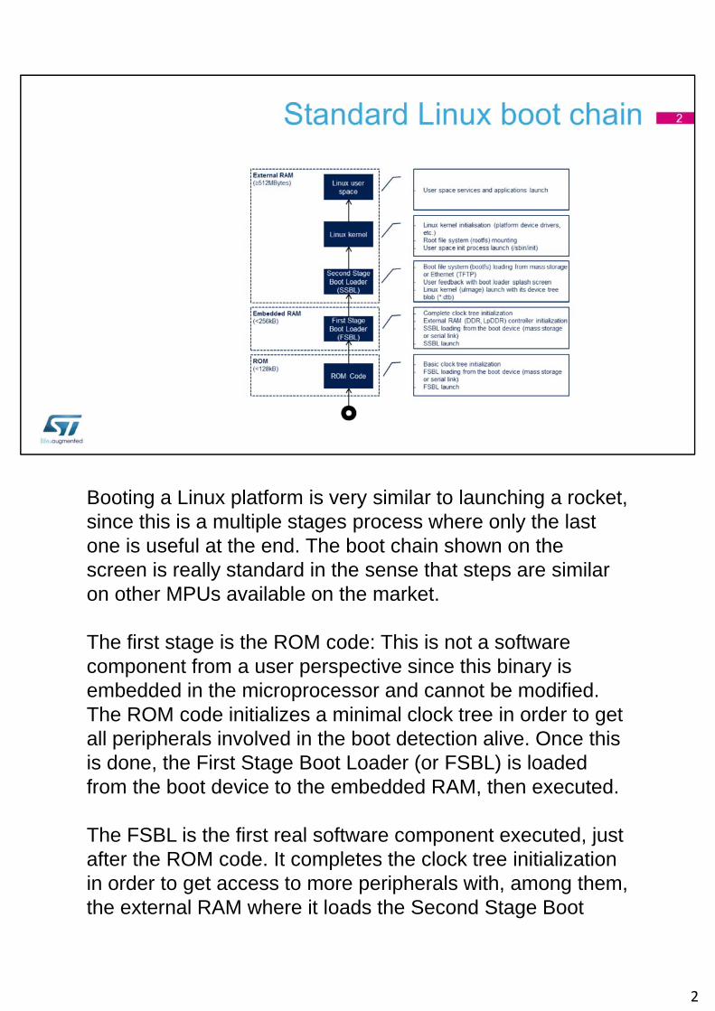
Booting a Linux platform is very similar to launching a rocket, since this is a multiple stages process where only the last one is useful at the end. The boot chain shown on the screen is really standard in the sense that steps are similar on other MPUs available on the market.
The first stage is the ROM code: This is not a software component from a user perspective since this binary is embedded in the microprocessor and cannot be modified. The ROM code initializes a minimal clock tree in order to get all peripherals involved in the boot detection alive. Once this is done, the First Stage Boot Loader (or FSBL) is loaded from the boot device to the embedded RAM, then executed.
The FSBL is the first real software component executed, just after the ROM code. It completes the clock tree initialization in order to get access to more peripherals with, among them, the external RAM where it loads the Second Stage Boot
2
Loader (or SSBL) before execution.
The most famous SSBL used all around the world is U-Boot. Its mission is to load the Linux kernel into the external RAM from a given boot device among the ones supported by the ROM code or even other ones like the Ethernet, for instance. The SSBL has a quite large features set and it is also often used to display an image during the start up process, that is called the splash screen. The “boot file system” or “bootfs” contains most of the binaries needed by U-Boot: The splash screen image, the Linux kernel and the device tree blob that contains all initialization data given to Linux kernel.
The last action from U-Boot is a jump to Linux kernel entry point… and Linux is then alive ! The kernel starts by initializing all its device drivers then it mounts the “root file system” or “rootfs”, that contains all the user space applications and libraries.
The user space switch is realized when Linux kernel creates the “init” process, that launches the services and applications stored in the rootfs.
This figure shows the typical sizes of the successive memories embedding the boot chain components, from few hundreds of kilo bytes for the internal memories and up to several hundreds of mega bytes for the external memories.
2
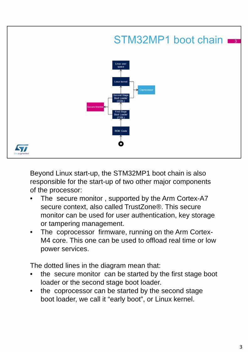
Beyond Linux start-up, the STM32MP1 boot chain is also responsible for the start-up of two other major components of the processor:• The secure monitor , supported by the Arm Cortex-A7
secure context, also called TrustZone®. This secure monitor can be used for user authentication, key storage or tampering management.
• The coprocessor firmware, running on the Arm Cortex-M4 core. This one can be used to offload real time or low power services.
The dotted lines in the diagram mean that:• the secure monitor can be started by the first stage boot
loader or the second stage boot loader.• the coprocessor can be started by the second stage
boot loader, we call it “early boot”, or Linux kernel.
3
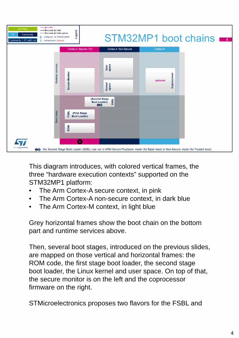
This diagram introduces, with colored vertical frames, the three “hardware execution contexts” supported on the STM32MP1 platform:• The Arm Cortex-A secure context, in pink• The Arm Cortex-A non-secure context, in dark blue• The Arm Cortex-M context, in light blue
Grey horizontal frames show the boot chain on the bottom part and runtime services above.
Then, several boot stages, introduced on the previous slides, are mapped on those vertical and horizontal frames: the ROM code, the first stage boot loader, the second stage boot loader, the Linux kernel and user space. On top of that, the secure monitor is on the left and the coprocessor firmware on the right.
STMicroelectronics proposes two flavors for the FSBL and
4
SSBL on STM32MP1: one puts the SSBL on secure side whereas the second one runs it in non-secure side. This is the meaning of the arrow in the SSBL box and those two options are further described in the following slides.
4
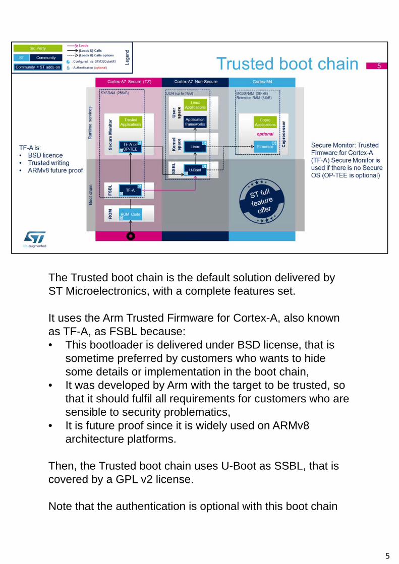
The Trusted boot chain is the default solution delivered by ST Microelectronics, with a complete features set.
It uses the Arm Trusted Firmware for Cortex-A, also known as TF-A, as FSBL because:• This bootloader is delivered under BSD license, that is
sometime preferred by customers who wants to hide some details or implementation in the boot chain,
• It was developed by Arm with the target to be trusted, so that it should fulfil all requirements for customers who are sensible to security problematics,
• It is future proof since it is widely used on ARMv8 architecture platforms.
Then, the Trusted boot chain uses U-Boot as SSBL, that is covered by a GPL v2 license.
Note that the authentication is optional with this boot chain
5
so it can run on any STM32MP1 security variant, having or not the Secure boot option.
OP-TEE secure OS is optional and can only be used to run Trusted Applications on STM32MP1 platforms. Otherwise, TF-A Secure Monitor, so called sp_min, is used to implement the minimum set of secure services expected to support the platform.
5
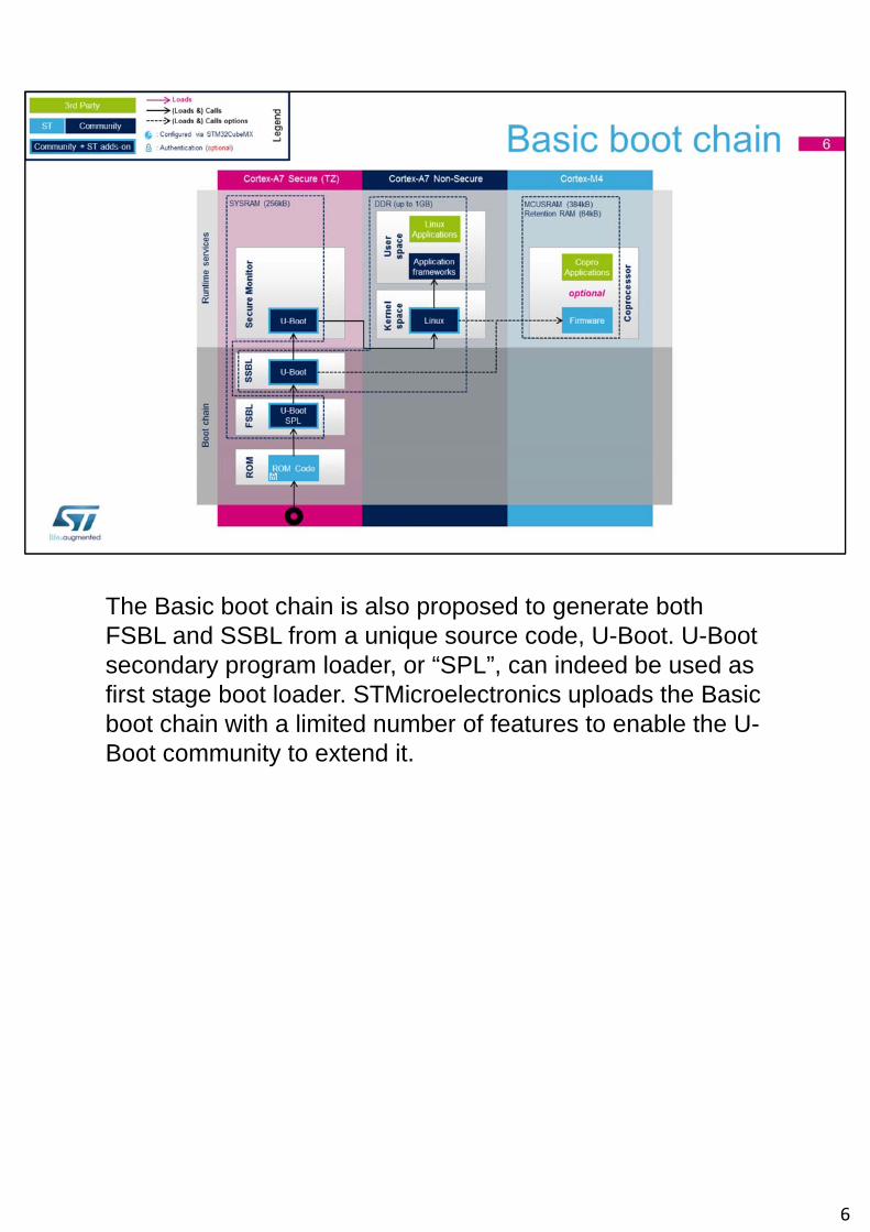
The Basic boot chain is also proposed to generate both FSBL and SSBL from a unique source code, U-Boot. U-Boot secondary program loader, or “SPL”, can indeed be used as first stage boot loader. STMicroelectronics uploads the Basic boot chain with a limited number of features to enable the U-Boot community to extend it.
6
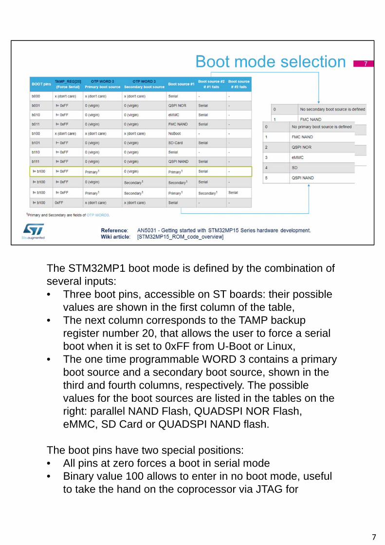
The STM32MP1 boot mode is defined by the combination of several inputs:• Three boot pins, accessible on ST boards: their possible
values are shown in the first column of the table,• The next column corresponds to the TAMP backup
register number 20, that allows the user to force a serial boot when it is set to 0xFF from U-Boot or Linux,
• The one time programmable WORD 3 contains a primary boot source and a secondary boot source, shown in the third and fourth columns, respectively. The possible values for the boot sources are listed in the tables on the right: parallel NAND Flash, QUADSPI NOR Flash, eMMC, SD Card or QUADSPI NAND flash.
The boot pins have two special positions:• All pins at zero forces a boot in serial mode• Binary value 100 allows to enter in no boot mode, useful
to take the hand on the coprocessor via JTAG for
7
firmware development without Linux
Let’s consider the example highlighted in green: To configure your board to always boot on SD card, that is the primary source number 4 in the table on the right, then write 4 as the primary boot source in OTP WORD 3. If the ROM code does not succeed to boot on the SD card, then it falls back to a serial boot as the secondary boot source is virgin in OTP.
The tables in this slide are copied from the ST Wiki article given in the bottom of this slide, so you can easily find them later on.
7
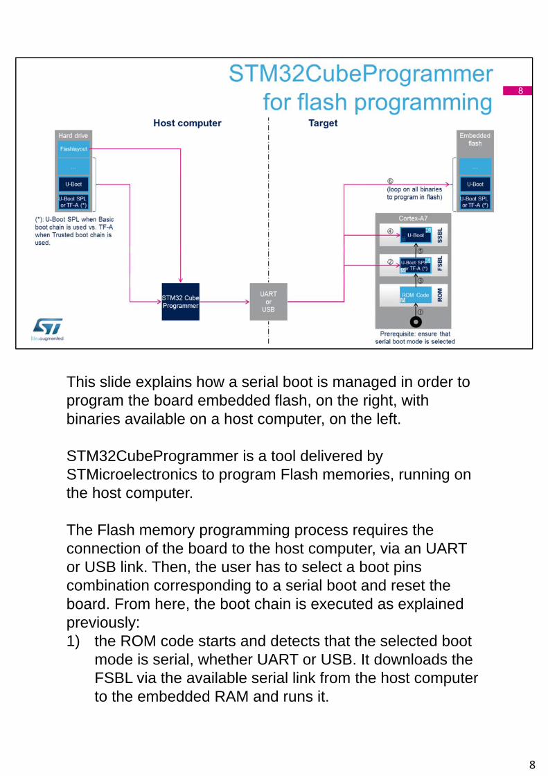
This slide explains how a serial boot is managed in order to program the board embedded flash, on the right, with binaries available on a host computer, on the left.
STM32CubeProgrammer is a tool delivered by STMicroelectronics to program Flash memories, running on the host computer.
The Flash memory programming process requires the connection of the board to the host computer, via an UART or USB link. Then, the user has to select a boot pins combination corresponding to a serial boot and reset the board. From here, the boot chain is executed as explained previously:1) the ROM code starts and detects that the selected boot
mode is serial, whether UART or USB. It downloads the FSBL via the available serial link from the host computer to the embedded RAM and runs it.
8
2) The FSBL does the same to get the SSBL from the host computer and copy it to the DDR for execution.
3) The SSBL asks for the Flashlayout to the host computer. The Flashlayout contains a textual description of the expected flash memory mapping, partition per partition.
4) The boot chain remains in a loop in SSBL until the end of the flash programming process, following the instructions from the Flashlayout.
When this sequence is finished, the user can change the boot pins to select the freshly programmed flash as boot device and reset its board to boot on it.
8
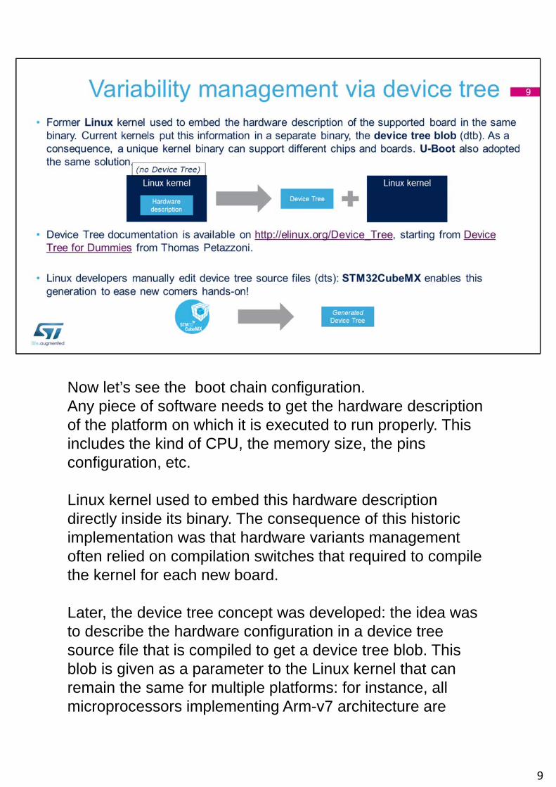
Now let’s see the boot chain configuration.Any piece of software needs to get the hardware description of the platform on which it is executed to run properly. This includes the kind of CPU, the memory size, the pins configuration, etc.
Linux kernel used to embed this hardware description directly inside its binary. The consequence of this historic implementation was that hardware variants management often relied on compilation switches that required to compile the kernel for each new board.
Later, the device tree concept was developed: the idea was to describe the hardware configuration in a device tree source file that is compiled to get a device tree blob. This blob is given as a parameter to the Linux kernel that can remain the same for multiple platforms: for instance, all microprocessors implementing Arm-v7 architecture are
9
supported with a unique Linux kernel configuration that is called multi_v7_config.
U-Boot adopted the same device tree concept and Arm follows the same trend in TF-A, so STMicroelectronics widely uses the device tree for all platform configuration data, including DDR configuration.
Linux developers are manually editing the device tree. On the other hand, STMicroelectronics customers are widely using the STM32CubeMX tool to configure the STM32Cube firmware for STM32 microcontrollers. So it has been decided to extend the tool with a DDR tuning function and make it able to generate the device tree for STM32MP1microprocessors to configure the internal peripherals. This should ease the move from the MCU world to the MPU one for people who are discovering the Linux environment.
9
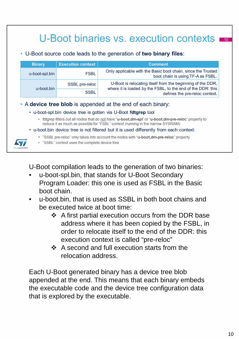
U-Boot compilation leads to the generation of two binaries:• u-boot-spl.bin, that stands for U-Boot Secondary
Program Loader: this one is used as FSBL in the Basic boot chain.
• u-boot.bin, that is used as SSBL in both boot chains and be executed twice at boot time: A first partial execution occurs from the DDR base
address where it has been copied by the FSBL, in order to relocate itself to the end of the DDR: this execution context is called “pre-reloc”
A second and full execution starts from the relocation address.
Each U-Boot generated binary has a device tree blob appended at the end. This means that each binary embeds the executable code and the device tree configuration data that is explored by the executable.
10
U-Boot device tree embeds two special properties:• “u-boot,dm-spl” that stands for “U-Boot Driver Model -
Secondary Program Loader”• “u-boot,dm-pre-reloc” that stands for “U-Boot Driver
Model – pre relocation”
Let’s see how they are used…
Since U-Boot SPL is executed in the internal RAM that has a limited size, the device tree blob needs to be filtered in order to remove nodes that are useless in the FSBL context. This is done using the “fdtgrep” U-Boot tool, that removes all nodes that do not have “u-boot,dm-spl” or “u-boot,dm-pre-reloc” from the dtb file.
u-boot.bin does not have this memory size constraint but it would be wasting time to do too many initialization steps in the “pre-reloc” context. That is why U-Boot is only taking into account the “u-boot,dm-pre-reloc” tagged nodes while running in the “pre-reloc” context whereas all nodes are taken into account after the “pre-reloc” phase.
10
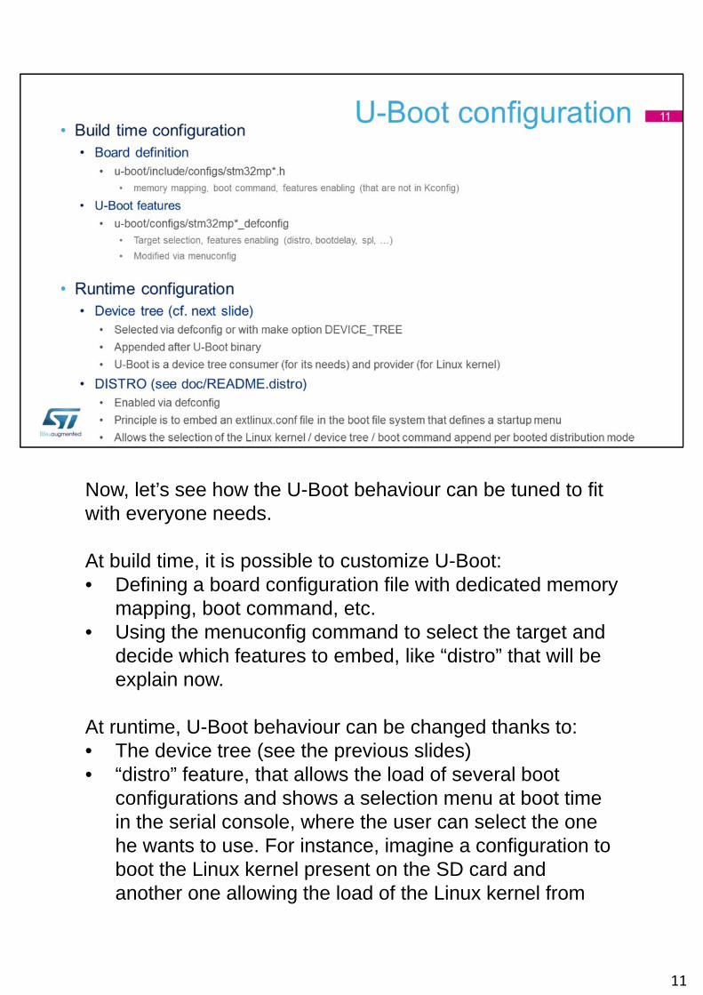
Now, let’s see how the U-Boot behaviour can be tuned to fit with everyone needs.
At build time, it is possible to customize U-Boot:• Defining a board configuration file with dedicated memory
mapping, boot command, etc.• Using the menuconfig command to select the target and
decide which features to embed, like “distro” that will be explain now.
At runtime, U-Boot behaviour can be changed thanks to:• The device tree (see the previous slides)• “distro” feature, that allows the load of several boot
configurations and shows a selection menu at boot time in the serial console, where the user can select the one he wants to use. For instance, imagine a configuration to boot the Linux kernel present on the SD card and another one allowing the load of the Linux kernel from
11
the network, directly from the developer host computer where it was compiled.
11
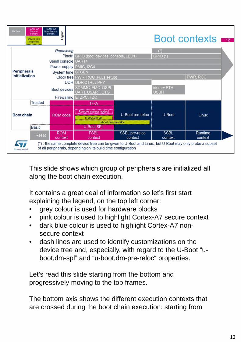
This slide shows which group of peripherals are initialized all along the boot chain execution.
It contains a great deal of information so let’s first start explaining the legend, on the top left corner:• grey colour is used for hardware blocks• pink colour is used to highlight Cortex-A7 secure context• dark blue colour is used to highlight Cortex-A7 non-
secure context• dash lines are used to identify customizations on the
device tree and, especially, with regard to the U-Boot “u-boot,dm-spl” and “u-boot,dm-pre-reloc“ properties.
Let’s read this slide starting from the bottom and progressively moving to the top frames.
The bottom axis shows the different execution contexts that are crossed during the boot chain execution: starting from
12
the reset, there are the ROM context, the FSBL, the SSBL pre-reloc and the SSBL after relocation that finally leads to the runtime context where Linux is running.
Just above is the mapping of the Trusted and Basic boot chains components on top of those contexts, with the coverage of the “u-boot,dm-spl” and “u-boot,dm-pre-reloc“ properties. Since TF-A does not have anything equivalent to U-Boot fdtgrep tool, the only way to optimize its device tree size is to remove useless nodes directly in the dts files.
The upper part of this slide shows the peripherals initialization order, beyond the ROM code context:• The firewalling consists in defining which peripheral can
be used by which context so it is setup very early, by the FSBL.
• The FSBL supports the same set of boot devices as the ROM code, whereas the SSBL extends this list with USB Host and Ethernet.
• The DDR controller initialization is applied by the FSBL and remains visible in the pre-reloc context since it contains the DDR size, used to perform the relocation.
• The clock tree is one of the primary configuration applied by the FSBL. It may eventually be modified at runtime, later on.
• The system time for the Cortex-A7 generic timer is provided by STGEN, that is initialized in the FSBL.
• The power supplies are provided by the external PMIC, that is controlled via I2C4 on ST boards. So both are first initialized in the FSBL and updated all along the application needs at runtime.
• The UART4 is used as serial console from all contexts on ST boards.
• The GPIOs are progressively initialized by each context, step by step.
12
• All the other peripherals are initialized by U-Boot or Linux when needed.
12
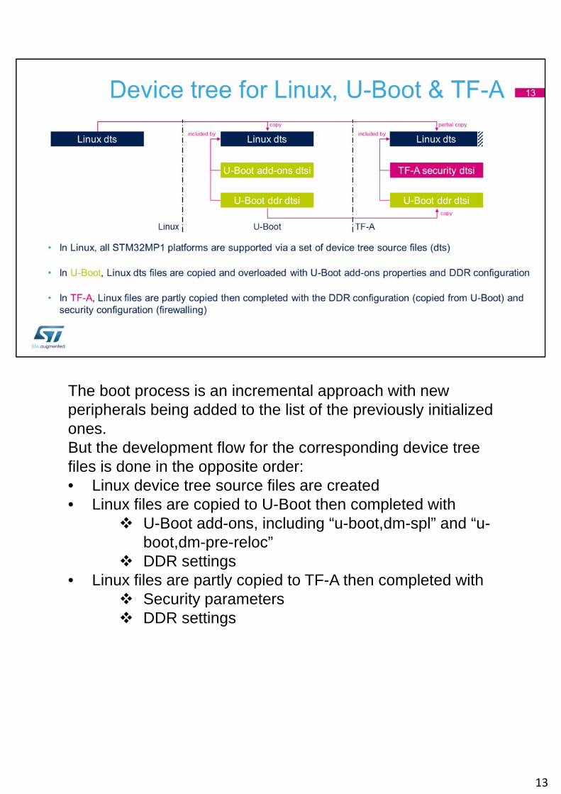
The boot process is an incremental approach with new peripherals being added to the list of the previously initialized ones.But the development flow for the corresponding device tree files is done in the opposite order:• Linux device tree source files are created• Linux files are copied to U-Boot then completed with
U-Boot add-ons, including “u-boot,dm-spl” and “u-boot,dm-pre-reloc”
DDR settings• Linux files are partly copied to TF-A then completed with
Security parameters DDR settings
13
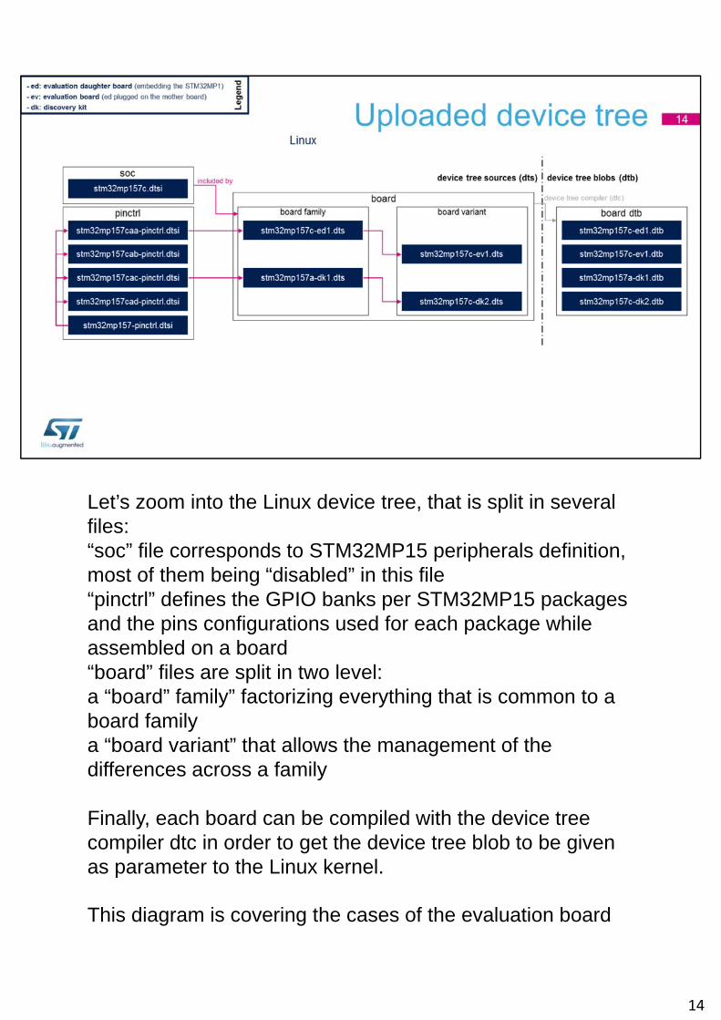
Let’s zoom into the Linux device tree, that is split in several files:“soc” file corresponds to STM32MP15 peripherals definition, most of them being “disabled” in this file“pinctrl” defines the GPIO banks per STM32MP15 packages and the pins configurations used for each package while assembled on a board“board” files are split in two level:a “board” family” factorizing everything that is common to a board familya “board variant” that allows the management of the differences across a family
Finally, each board can be compiled with the device tree compiler dtc in order to get the device tree blob to be given as parameter to the Linux kernel.
This diagram is covering the cases of the evaluation board
14
“ev1” and the discovery kit “dk2”. Those boards are variants of the evaluation daughter board “ed1” and the discovery kit “dk1”.
STMicroelectronics maximizes the use of open source software and the upload to communities. So all those device tree files are uploaded to Linux repository and this is also true for the two upcoming slides, for U-Boot and TF-A.
14
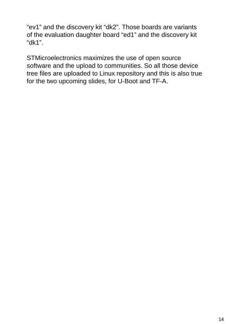
Starting from a set of Linux device tree files, this diagram shows what files are added in U-Boot, mainly to do some overlay with U-Boot “u-boot,dm-spl” and “u-boot,dm-pre-reloc” properties but also for the DDR controller initialization.
On the right, the build process generates u-boot.dtb and u-boot-spl.dtb files for each board.
15
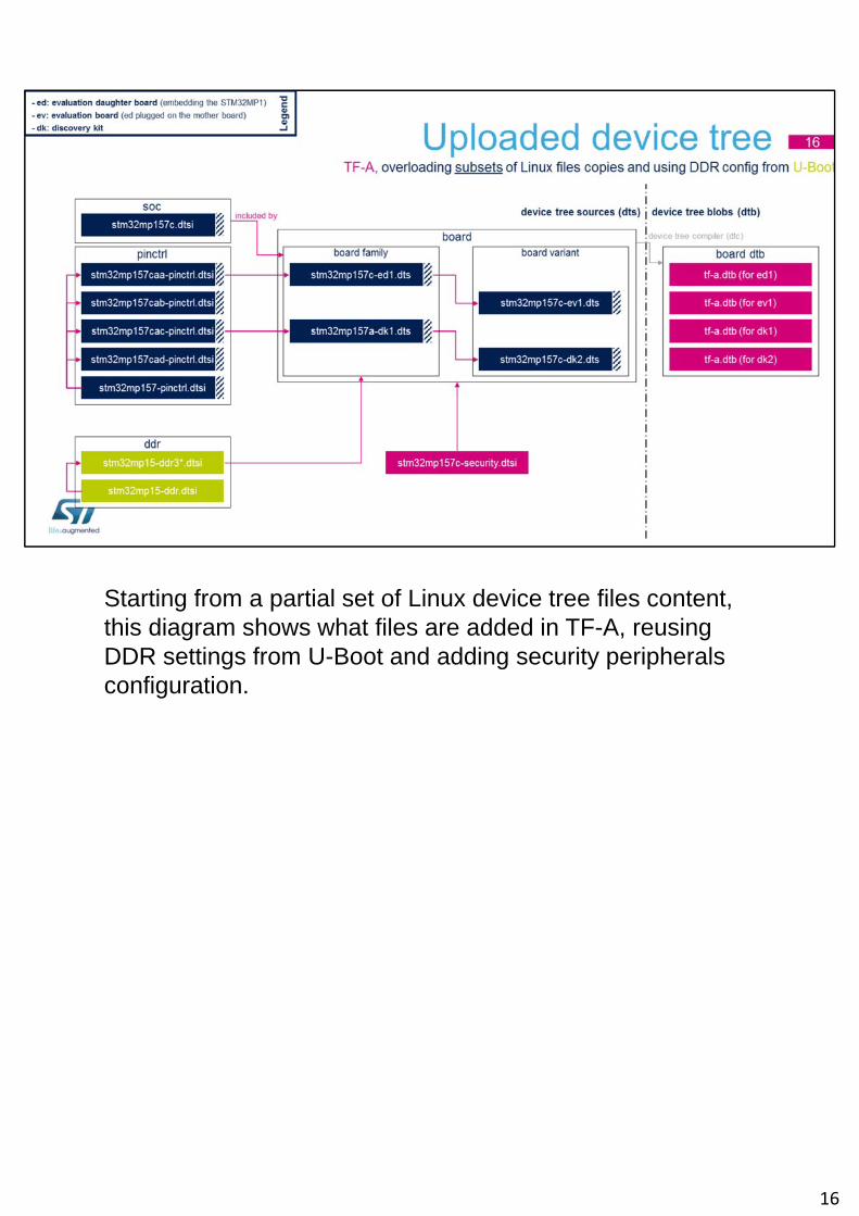
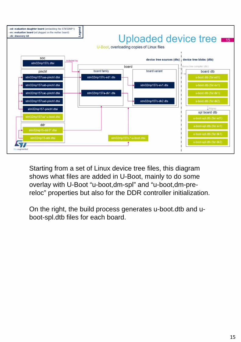
Starting from a partial set of Linux device tree files content, this diagram shows what files are added in TF-A, reusing DDR settings from U-Boot and adding security peripherals configuration.
16
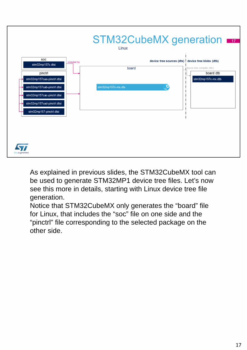
As explained in previous slides, the STM32CubeMX tool can be used to generate STM32MP1 device tree files. Let’s now see this more in details, starting with Linux device tree file generation.Notice that STM32CubeMX only generates the “board” file for Linux, that includes the “soc” file on one side and the “pinctrl” file corresponding to the selected package on the other side.
17
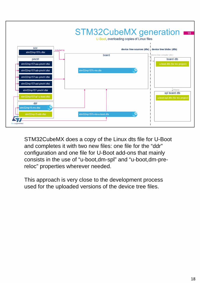
STM32CubeMX does a copy of the Linux dts file for U-Boot and completes it with two new files: one file for the “ddr” configuration and one file for U-Boot add-ons that mainly consists in the use of “u-boot,dm-spl” and “u-boot,dm-pre-reloc” properties wherever needed.
This approach is very close to the development process used for the uploaded versions of the device tree files.
18
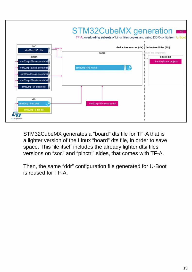
STM32CubeMX generates a “board” dts file for TF-A that is a lighter version of the Linux “board” dts file, in order to save space. This file itself includes the already lighter dtsi files versions on “soc” and “pinctrl” sides, that comes with TF-A.
Then, the same “ddr” configuration file generated for U-Boot is reused for TF-A.
19
To boot properly, the right boot device must be selected via the boot pins or the OTP boot source. The selected boot flash must then be properly partitioned to allow the ROM code booting on it.This section shows how the ROM code is looking for the FSBL binary in the selected flash. It also describes the complete flash memory mapping that is implemented in the STMicroelectronics OpenSTLinux distribution.
20
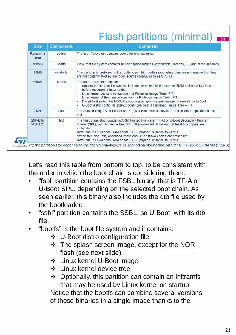
Let’s read this table from bottom to top, to be consistent with the order in which the boot chain is considering them:• “fsbl” partition contains the FSBL binary, that is TF-A or
U-Boot SPL, depending on the selected boot chain. As seen earlier, this binary also includes the dtb file used by the bootloader.
• “ssbl” partition contains the SSBL, so U-Boot, with its dtbfile.
• “bootfs” is the boot file system and it contains: U-Boot distro configuration file, The splash screen image, except for the NOR
flash (see next slide) Linux kernel U-Boot image Linux kernel device tree Optionally, this partition can contain an initramfs
that may be used by Linux kernel on startupNotice that the bootfs can combine several versions of those binaries in a single image thanks to the
21
Flattened Image Tree format, that is out of scope of this training
• “vendorfs” file system is used to store third parties binaries to ensure that they cannot be contaminated by unwished licences, such as GPL v3, that are used in the “rootfs”.
• “rootfs” file system contains all user space binaries, so mainly kernel modules, executables and libraries. This is usually the biggest partition, that can be up to 800MB wide.
• “userfs” file system contains user data and STMicrolectronics examples.
21
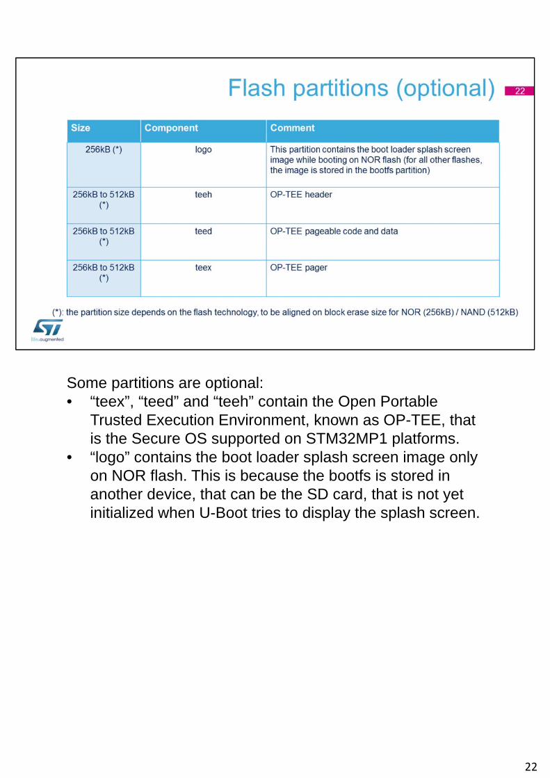
Some partitions are optional:• “teex”, “teed” and “teeh” contain the Open Portable
Trusted Execution Environment, known as OP-TEE, that is the Secure OS supported on STM32MP1 platforms.
• “logo” contains the boot loader splash screen image only on NOR flash. This is because the bootfs is stored in another device, that can be the SD card, that is not yet initialized when U-Boot tries to display the splash screen.
22
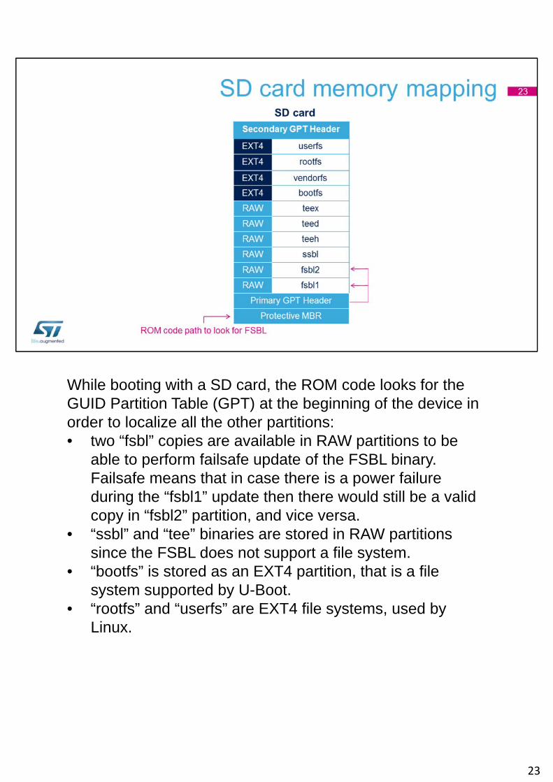
While booting with a SD card, the ROM code looks for the GUID Partition Table (GPT) at the beginning of the device in order to localize all the other partitions:• two “fsbl” copies are available in RAW partitions to be
able to perform failsafe update of the FSBL binary. Failsafe means that in case there is a power failure during the “fsbl1” update then there would still be a valid copy in “fsbl2” partition, and vice versa.
• “ssbl” and “tee” binaries are stored in RAW partitions since the FSBL does not support a file system.
• “bootfs” is stored as an EXT4 partition, that is a file system supported by U-Boot.
• “rootfs” and “userfs” are EXT4 file systems, used by Linux.
23
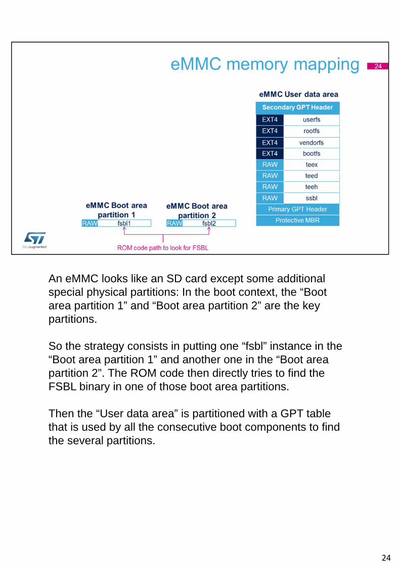
An eMMC looks like an SD card except some additional special physical partitions: In the boot context, the “Boot area partition 1” and “Boot area partition 2” are the key partitions.
So the strategy consists in putting one “fsbl” instance in the “Boot area partition 1” and another one in the “Boot area partition 2”. The ROM code then directly tries to find the FSBL binary in one of those boot area partitions.
Then the “User data area” is partitioned with a GPT table that is used by all the consecutive boot components to find the several partitions.
24
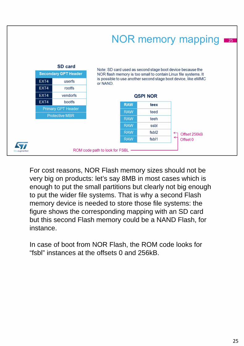
For cost reasons, NOR Flash memory sizes should not be very big on products: let’s say 8MB in most cases which is enough to put the small partitions but clearly not big enough to put the wider file systems. That is why a second Flash memory device is needed to store those file systems: the figure shows the corresponding mapping with an SD card but this second Flash memory could be a NAND Flash, for instance.
In case of boot from NOR Flash, the ROM code looks for “fsbl” instances at the offsets 0 and 256kB.
25
NAND Flash memory is the cheaper Flash technology that exists but it is also the most complex to manage !
Being cheaper implies that it is widely used…
… and, on the other hand, it is important to understand the physical organisation of a NAND flash and the two main defects that make it harder to play with:• On physical side, a NAND flash is split in “blocks” that
are themselves split in “pages”. Each page contains a “user area” where the data is stored and a “spare area” used to store meta data.
• First kind of defect: some blocks may be bad. Over time, some of them becomes bad during the product life, due to wearing, but some of them are already bad out of production. A special tag in the spare area is used to identify factory bad blocks.
• Second kind of defect: due to physical phenomenon such
26
as electrical leakage or read disturb effect, some bits may toggle in pages. So error detection and correction mechanisms are needed in order to overcome this issue, storing the Error Correction Code in the spare area.
Now, let’s consider the software to manage the NAND flash:• Any piece of software must be able to detect and correct
errors in the pages. This is mandatory.• A software not able to manage a bad block replacement
strategy simply uses a “skip bad block” method, that consists in jumping to the next block when a bad block is met.
• A first level of bad block management comes with the MTD, meaning Memory Technology Device, that allows the management of bad blocks inside the MTD volumes. MTD does not allow the mitigation of the wearing issues. This is why the binaries contained in MTD partitions need to be there in several copies.
• The ultimate level of management for the NAND Flash is offered by the Unsorted Block Image that exposes a perfect volume via logical blocks to the upper layers. The UBI is then managing the translation to valid physical blocks and takes care about the wear levelling, so no need to duplicate data inside UBI volumes and UBI File System that are defined inside.
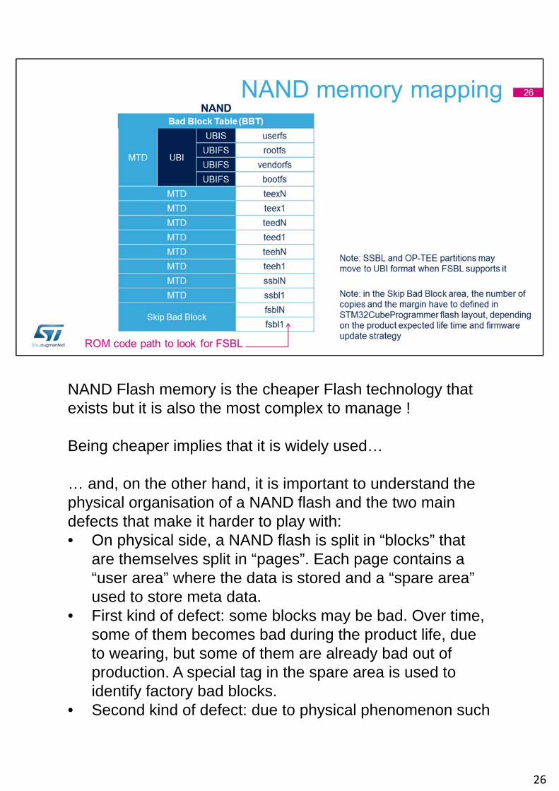
This being said, the diagram above can now be understood:• The ROM code uses the “skip bad block” strategy to look
for a valid fsbl instance starting from the offset 0 in the NAND flash.
• ssbl and tee partitions are stored in multiple copies inside independent MTD volumes.
• bootfs, rootfs and userfs are defined as UBIFS partitions inside a common MTD volume.
26

The slide is an overview of the image signature and authentication process as it is used on STM32 MPUs.As a prerequisite, here are the minimal acronyms to know for a correct understanding:• A payload is a binary file on which a cryptographic
operation is done.• ECDSA256 stands for Elliptic Curve Digital Signature
Algorithm with 256 bits keys pair. It is an asymmetric cryptographic algorithm able to encrypt a payload via a 256 bits Private key then decrypt it via the corresponding 512 bits Public key.
• SHA256 means Secure Hash Algorithm generating a 256 bits hash from an input payload.
• It is a common practise to store a Public key hash in order to check the Public key integrity, later on.
• A Signature is made of the cryptographic hash of a payload containing the initial payload to authenticate plus the Public key. A signature is often called HMAC,
27
standing for Hashed Message Authentication Code.
Thanks to refer to cryptographic documentation and training for further information.
This diagram explains the complete flow that is put in place to perform FSBL binary authentication with the ROM code:1) First of all, the “Key generator” tool is used on host side
to generate an ECDSA keys pair, so a “Private key” and the corresponding “Public key”. The tool also generates a “Public key hash” via a SHA256 operation.
2) “STM32CubeProgrammer” includes an “OTP burning tool” that can be used to write the “Public key hash” into the STM32MP1 BSEC non volatile memory.
3) The “Signing tool” is used on host side to compute the SHA256 hash of the FSBL payload plus the “Public key” and the file “Header”.
4) This hash is encrypted with ECDSA256 using the “Private key” to get the payload “Signature”. The “Signing tool” finally generates a signed file, containing the “Payload”, the “Public key”, the “Header” and the “Signature”. This signed file is the one used by “STM32CubeProgrammer” to populate the embedded flash.
5) When the STM32MP1 target is reset, the ROM code starts by computing the SHA256 hash of the “Public key” available in the signed file. Then, it compares this hash with the one stored in the STM32MP1 BSEC non volatile memory: if it is different, the authentication process fails. Otherwise, it continues…
6) The ROM code computes the SHA256 of the FSBL payload plus the “Public key” and the file “Header”. It compares this hash to the value resulting from the decrypted “Signature” with the “Public key” that has just been authenticated: if the comparison fails, then the
27
authentication process fails. Otherwise, the authentication is successful and the ROM code goes on with the boot process.
27