Presentation Control relays - Schneider Electric · The range of RH plug-in control relays with...
21
The range of RH plug-in control relays with single socket type common to all models and standard front face includes the following models of 5 A relays with 4 C/O contacts, for a.c. and d.c. control: instantaneous relays, mechanical latching relays (memory relays), time delay relays, fleeting contact relays, flashing relays, sequencer step module. The RH relay is designed to provide true miniaturisation, combining minimum installation size with: ensured dielectric strength for hard-wired equipment, standard pattern contact points compatible with automatic wiring methods, direct accessibility to connection points when wiring. The highly versatile RH range offers numerous mounting and wiring possibilities for use in a wide variety of automation equipment installations. The vibration resistance (severity 55 A conforming to IEC 68-2-6) quoted on pages 28002/2 and 28002/5 are for back wired sockets clipped onto a rigid plate, or for front wired sockets screwed onto a rigid panel. The range Miniaturisation Vibration resistance Control relays RH plug-in relays Presentation Characteristics : pages 28002/2 to 28002/9 References : pages 28003/2 to 28003/5 Dimensions, schemes : pages 28004/2 to 28004/5 Instantaneous relay Latching relay Fleeting contact relay
Transcript of Presentation Control relays - Schneider Electric · The range of RH plug-in control relays with...

Presentation
pages 28002/2 to 28002/9 pages 28003/2 to 28003/5
Control relaysRH plug-in relays
The range of RH plug-in control relays with single socket type common to all models and standard front face includes thefollowing models of 5 A relays with 4 C/O contacts, for a.c. and d.c. control:
/ instantaneous relays,
/ mechanical latching relays (memory relays),
/ time delay relays,
/ fleeting contact relays,
/ flashing relays,
/ sequencer step module.
The RH relay is designed to provide true miniaturisation, combining minimum installation size with:
/ ensured dielectric strength for hard-wired equipment,
/ standard pattern contact points compatible with automatic wiring methods,
/ direct accessibility to connection points when wiring.
The highly versatile RH range offers numerous mounting and wiring possibilities for use in a wide variety of automationequipment installations.
The vibration resistance (severity 55 A conforming to IEC 68-2-6) quoted on pages 28002/2 and 28002/5 are for backwired sockets clipped onto a rigid plate, or for front wired sockets screwed onto a rigid panel.
The range
Miniaturisation
Vibration resistance
Characteristics : References : Dimensions, schemes :
Instantaneous relay
Latching relay
Fleeting contact relay
pages 28004/2 to 28004/5

Presentation
pages 28002/2 to 28002/9 pages 28003/2 to 28003/5
Plug-in relays RH control relays
1
3
2
2
4
5
6
1
2
2
The front of all RH relays have a standard appearance.
The self-adhesive function legend is placed at the top. This legend can be madeup and positioned by the user as required.The hinged flap 1 has three functions:- acts as an extractor pull tab,- provides protection against dust and accidental adjustment of settings acces-sible on the front face: operator, indicators, etc,- sealing 2 of these active components if necessary.In operation, the flap must always be down.
The active components differ according to the relay function, ie:/ for instantaneous and latching relays:
/ for time delay, fleeting contact and flashing relays:
All RH relays have the same type of base, with outlets evenly spaced at 7.62 mmintervals, both vertically and horizontally.This triple 2.54 mm module allows:- the use of automatic wiring methods,- the establishment of leakage paths, so ensuring a dielectric strength of 2500V with the relay wired.Also, the outlets are protected female sockets which makes it possible:- to provide mechanical protection for these outlets during transport andinstallation,- to incorporate within the relay (a plug-in and replaceable component) all activecomponents, including plug-in connection clips (note that inside the relay, eachcontact carrier plate and its corresponding output connection clip are in onepiece, with no soldered joins),- to keep within the socket (a fixed and wired component) only very simple maleconductor components, which makes these sockets very reliable.
RH relays clip securely into their socket.They are released by pressing the release tabs with a screwdriver or a finger. The relay can then be removed by simply pulling the extractor pull tab 1.If the relay is accidentally released, it must be fully extracted before beingclipped back into place.
The normal mounting position, with front face vertical and extractor pull tabpointing down is shown in the figure above.The label gives the wiring scheme for the device together with other information(type, rating, voltage, etc).Mounting the relay in any other position has virtually no effect on its operatingcharacteristics.
Front face
- manual operator 3,- mechanical state indicator 3,
- timing range selector switch 4, display 5,- 1 or 2 relay state indicators 6.
Base
Locking the relay into the socket
RH relay operating position
Characteristics : References : Dimensions, schemes :
pages 28004/2 to 28004/5
Presentation
pages 28002/2 to 28002/9 pages 28003/2 to 28003/5
Plug-in relays RH control relays
X
Z+
A+
C
E1 E2 E3 E4
12 1411
F2
F1 F3
22 2421
C
X
Z+
A+
C
E1 E2 E3 E4
12 14 11
F2
F1 F3
22 24 21
The analysis of an industrial process generally involves breaking it down intoa succession of clearly defined basic tasks or actions, performed in a set order(opening a valve, for example, followed by starting a mixer, etc.).
The end of one operation generally establishes the start of the next operation.The RH sequencer is a simple way of controlling this type of process. Acting asthe backbone of the automated system, it consists of a series of "step modules",one for each step in the sequential process.
Each "step module" in the sequencer consists of :
/ an RHK-412 mechanical latched relay, with d.c. coil,/ a special socket, RHZ-42. The sockets clip onto a 35 mm rail and also plug
into each other sideways, so providing electrical connection between them-selves.
The sequencer is therefore made up of one or more rows, as required, ofmodules which plug and clip together to form the internal basic scheme of thesequencer, without any need for wiring between sockets.
The latching relay in each module comprises :/ 2 internal switching contacts,/ 2 changeover operating contacts.
When the step module is activated, the energising coil actuates these 4contacts :/ one of the internal switching contacts deactivates the previous module;/ the other internal switching contact supplies the validation circuit for the next
module,/ the 2 operating changeover contacts are available for switching actions
associated with the step (motors, etc.).
Supply terminalThe following polarities must be complied with :/ Z+ : general reset./ A+ : + supply to the sequencer./ C : - supply.All Z+, A+ and C terminals in a horizontal row of step modules are electricallyconnected to each other.
Control terminalsBetween E1 and E4, wiring of energisation condition(s).E2, E3 : spare terminals.For logic connections required between non-adjacent modules :F1 = Sends reset instruction “n”,F2 = Sends validation instruction “n”,F3 and X = Receives reset instruction,E1 = Receives validation instruction.Terminal X is equivalent to terminal F3 but introduces a non-return diode,located in the socket, into the wired reset circuit. It is used in certain circuits, inparticular for the step preceding a jump of one or more steps.Please consult the technical manual on the "RH Electrical Sequencer" for moredetailed information.
RH sequencer
Sequencer composition
Step module scheme
Socket RHZ-42 Terminal marking
Validation from previous module
Reset
Supply
De-energisationof previous module
Energisationcoil
De-energisation coil
2 changeover operating contacts
2 internalswitching contacts
Validation from previous module
De-energisationfrom previous module
De-energisation
Energisation condition
Characteristics : References : Dimensions, schemes :
RHZ-42 RHK-412/
pages 28004/2 to 28004/5

Definitions
pages 28002/2 to 28002/9 pages 28003/2 to 28003/5
Plug-in relaysRH control relays
In
0.63In
The time taken for the current to establish within a load, switched by an RH relaycontact for example, depends on the time constant for this load, or moreprecisely for the whole of the circuit.
With d.c. control, this is the ensured value of the current broken in a resistive orinductive circuit, with a given time constant, at a voltage U and for a specifiednumber of operating cycles.
It is also often expressed as power broken in W (it is in fact a fictitious power inVA = the product of I before breaking, multiplied by U at the contact terminalsafter breaking).
With a.c. control, this is the value in amps of the current broken in a resistive orinductive circuit, for a given power factor (cos ϕ), at a voltage U and for aspecified number of operating cycles.
It is also often expressed in VA.
For each variable quantity, and within a permissible variation range, this isexpressed as % drift of the time delay per unit variation in the variable quantity(or for the total permissible variation range).
RH relays, all models
Time constant This is the ratio L/R, expressed in milliseconds, between the inductance and the resistance of a load.
Breaking The breaking time with d.c. control depends on the time constant of the circuitand also on the opening distance of the switching contact : the inductive energy(1/2 Li2) is in fact dissipated in the arc which appears at the contact terminals.With a.c. control, breaking occurs when the current passes through zero.When a contact opens, an overvoltage is crated t its terminals; the higher theinductance of the circuit and the faster the contact opens, the higher theovervoltage (u = L.di/dt).
Variable quantities All quantities (ambient temperature, supply voltage...) whose variations arelikely to affect operation of the relay.
Rated thermal current The highest value of current (rms value for a.c.) which a closed contact cansustain continuously, under the conditions specified by the manufacturer,without its temperature rise exceeding the limits given in the standards.
Making current The highest value of current (rms value for a.c.) which a contact is capable of makingonto.
RH time delay relays
Repeat accuracy Repeat accuracy defines the variation in time delays obtained on a single relay,for a series of successive operating cycles, without modifying the setting and atrated conditions for temperature, voltage, etc
Setting accuracy This is the maximum ensured differential between the time delay set and thetime delay actually obtained, under normal conditions. This differential isexpressed as a % of the time delay per unit variation in the variable quantity(or for the total permissible variation range).
Time delay / The time delay- at switch-off or- On-delay or- on energisationstarts as soon as supply to the control circuit is switched on.
Reset time Minimum time required between the end of one time delay cycle and the start of the next.
Characteristics : References : Dimensions, schemes :
time makingconstant =
Ltime
R
/ The time delay- at switch-off or- Off-delay or- on de-energisationstarts as soon as supply to thecontrol circuit is switched off.
Breaking current according to the numberof operating cycles
Stability according to variationsin variable quantities
pages 28004/2 to 28004/5

Characteristics
pages 28001/2 to 28001/5 page 28003/2
Plug-in relays RH control relaysInstantaneous (RHN) and latching (RHK)
Type RHN RHK
Environment
Classification Standard version EDF, BV, USSR
Conforming to standards Standard version IEC 255, NF C 45-250, VDE 0435, BS 4794
Product approvals Standard version CSA, ASE, UR CSA, ASE, UR
Protective treatment Standard version “TC” “TC”
Rated insulation voltage V 250 250
Dielectric strength (relay “wired”) V 2500 2500
Ambient air temperature Storage °C - 40…+ 70 - 40…+ 70around the device
Operation (Conforming to 1C of IEC 255) °C - 5…+ 40 - 5…+ 40
Permissible for operation between 0.85 and 1.1 Un °C - 25…+ 60 - 25…+ 60
Operating positions Any Any
Vibration resistance Conforming to NF C 20-616 and IEC 68-2-6 Severity 55 A 6 g (10…55 Hz) 6 g (10…55 Hz)
Shock resistance Conforming to NF C 20-608Severity 50 A 50 g - 11ms 30 g - 11ms
Contact characteristics
Number of contacts 4 C/O 4 C/O
Rated thermal current For temperature ≤ 40 °C A 5 (RHN-41//) 5 (RHK-41//)
1 (RHN-42//) 1 (RHK-42//)
Minimum switching capacity At U min : 1 V or I min : 10 mA mVA 150 (RHN-41//) 150 (RHK-41//)
At U min : 1 V or I min : 1 mA mVA 50 (RHN-42//) 50 (RHK-42//)
Bounce time Maximum duration of a bounce ≤ 2 ms ms ≤ 10 ≤ 10
Volt drop For 3 A at 24 V mV ≤ 100 ≤ 100
Average resistance of contacts Socket + relay at 20 °C mΩ 30 30
Changeover time a.c. control circuit De-energising/Energising ms 0.5…6 0.5…6
Energising/De-energising ms 1…3 1…3
d.c. control circuit De-energising/Energising ms 1.2…4 1.2…4
Energising/De-energising ms 1…4 1…4
Presentation : References : Dimensions, schemes :
pages 28004/2 to 28004/5
Characteristics
pages 28001/2 to 28001/5 page 28003/2
Plug-in relays RH control relaysInstantaneous (RHN) and latching (RHK)
Type RHN RHK
Control circuit characteristics
Average consumption Coil n° 1 Coil n° 2at 20 °C a.c. control Inrush VA 4.5 6 2.5
Holding VA 2.5 3.5 1.3
d.c. control Inrush or W 1.6 1.6 2.9Holding
Permissible voltage variation Conforming to 1 C of IEC 255 0.8…1.1 Uc 0.8…1.1 Uc
Drop-out voltage d.c. control 0.10…0.3 Uc 0.10…0.3 Uc
a.c. control 0.15…0.5 Uc 0.15…0.5 Uc
Cos ϕ (a.c. control) Inrush 0.6 0.6
Holding 0.7 0.7
L/R (d.c. control) L/R, magnetic circuit Open ms 12 12
Closed ms 15 15
Other characteristics
Mechanical life (at Uc) In millions of operating cycles 20 10
Maximum operating rate In operating cycles per second 6 2
Operating time Between coil energisation and a.c. control ms 2…15 5…17(at rated voltage and at 20 °C) making of N/O contact
d.c. control ms 10…20 12…22
Between coil de-energisation and a.c. control ms 1.2…12 –making of N/C contact
d.c. control ms 2…7 –
Between energisation of trip a.c. control ms – 8…16coil and making of N/C contact
d.c. control ms – 10…14
Minimum pulse duration For latching or tripping of ms – ≥ 50RHK latch relay
Presentation : References : Dimensions, schemes :
pages 28004/2 to 28004/5
pages 28001/2 to 28001/5 page 28003/3 et 28003/4
Characteristics (continued)
Plug-in relays RH control relaysTime delay (RHT or RHR), fleeting contact (RHE or RHD), flashing (RHC)Presentation : References : Dimensions, schemes :
Type RHT, RHR RHE, RHD RHC
Environment
Classification Standard version EDF, BV, USSR
Conforming to standards Standard version IEC 255, NF C 45-250, VDE 0435
Product approvals Standard version CSA, ASE CSA, ASE CSA, ASE
Protective treatment Standard version “TC” “TC” “TC”
Rated insulation voltage V 250 250 250
Overvoltage protection Conforming to IEC 255-5 3 kV, 0.5 Joule 3 kV, 0.5 Joule 3 kV, 0.5 Joule
Dielectric strength, relay “wired” V 2500 2500 2500
Ambient air temperature Storage °C - 40…+ 70 - 40…+ 70 - 40…+ 70around the device
Operation (Conforming to 1 C of IEC 255) °C - 5…+ 40 - 5…+ 40 - 5…+ 40
Permissible for operation between 0.85 and 1.1 Un °C - 25…+ 60 - 25…+ 60 - 25…+ 60
Operating positions Any Any Any
Vibration resistance Conforming to NF C 20-616 Severity 55 A 6 g (10…55 Hz) 6 g (10…55 Hz) 6 g (10…55 Hz)and IEC 68-2-6
Shock resistance Conforming to NF C 20-608 Severity 50 A 50 g - 11 ms 50 g - 11 ms 50 g - 11 ms
Contact characteristics
Number of contacts 4 C/O 4 C/O 4 C/O
Rated thermal current For temperature ≤ 40 °C A 5 (RH/-41//) 5 (RH/-41//) 5 (RHC)1 (RH/-42//) 1 (RH/-42//)
Minimum switching capacity At U min: 1 V or I min: 10 mA mVA 150 (RH/-41//) 150 (RH/-41//) 150 (RHC)
At U min: 1 V or I min: 1 mA mVA 50 (RH/-42//) 50 (RH/-42//) –
Bounce time Maximum duration of bounce ≤ 2 ms ms ≤ 10 ≤ 10 ≤ 10
Volt drop For 3 A at 24 V mV ≤ 100 ≤ 100 ≤ 100
Average resistance Socket + relay at 20 °C mΩ 30 30 30
Changeover time a.c. control circuit De-energising/Energising ms 0.5…6 0.5…6 0.5…6
Energising/De-energising ms 1…3 1…3 1…3
d.c. control circuit De-energising/Energising ms 1.2…4 1.2…4 1.2…4
Energising/De-energising ms 1…4 1…4 1…4
pages 28004/2 to 28004/5

Characteristics
pages 28001/2 to 28001/5 page 28003/3 and 28003/4
Plug-in relays RH control relaysTime delay (RHT or RHR), fleeting contact (RHE or RHD), flashing (RHC)
(1) % of the maximum value of the range selected
Type RHT, RHR RHE, RHD RHC
Control circuit characteristics
Average consumption at 20 °C Output state 1 a.c. control VA 2.9 2.9 2.9
d.c. control W 2.5 2.5 2.5
For 220 V a.c. VA 3.5 3.5 3.5
Permissible voltage variation Conforming to 1 C of IEC 255 0.8…1.1 Uc 0.8…1.1 Uc 0.8…1.1 Uc
External control contact Type (only) Mechanical Mechanical Mechanical
Other characteristics
Mechanical life (at Uc) In millions of operating cycles 20 20 20
Status indication During time delay period (Green LED) Illuminated – –
On making of on-delay contacts (Red LED) Illuminated Illuminated Illuminated
Time delay (adjustable by 3 setting ranges Normal Long – –potentiometer on front face) (selected by switch on front face)
s 0.2…3 1.25…24 – –
s 1.5…30 12.5…240 – –
15…300 s 2…4 min – –
Repeat accuracy ± 1 % – –
Setting accuracy (1) Normal time delay ± 15 % – –
Long time delay ± 20 % – –
Reset time ms ≤ 100 – –
Stability Temperature (range : - 5…+ 40 °C) 0.14 % – –to influence quantities per °C around 20 °C
Voltage (range : 0.8…1.1 Uc) ms ± 20 – –for extreme limits
Immunity to During time delay period ms Up to 10 – –micro-breaks
After time delay period ms Up to 2 – –
Fleeting contacts Fleeting contact time ms – 200 –
Tolerance ms – - 20…+ 100 –
Response time at Uc ms – 10…30 (RHE) –and at 20 °C ms 35…65 (RHD)
Flashing relay Adjustable by potentiometer – – 0.5…5 orsymmetrical contact time on front face 2…30
Presentation : References : Dimensions, schemes :
pages 28004/2 to 28004/5
Characteristics (continued)
pages 28001/2 to 28001/5 page 28003/5
Plug-in relays RH control relaysSockets and termination adaptor for front wiring
Sockets
Type RHZ-11 RHZ-12 RHZ-13
Cabling With 2.8 x 0.5 tags for With 0.8 x 1.6 x 22 mm pins With 0.8 x 0.8 x 4.3 mm solder pinssoldering or for wire-wrap or termi-point for printed circuit boardFaston connectors at 7.62 (3 x 2.54 mm) centres at 7.62 (3 x 2.54 mm) centres
Rated thermal current A 5 5 5
Dielectric strength V 2500 2500 2500
Protection against Yes Yes Yesdirect finger contact
Function marking facility Using three AB1-R or AB1-G clip-in characters or AB1-SA1 blank clip-in legend plate
Relay-socket locking By simply clipping in the relay.To release, press the 2 red locking tabs.Warning : if accidentally released, the relay must be fully extracted before being clipped back into place.
Cabling capacity Solder tags, flexible cable 3 connections max. per termi- On all printed circuit boards1 x 1.5 mm2 or 2 x 1 mm2 point pin, flexible cable 2.54 mm pitch, see page 28004/2
Faston connector, flexible cable AWG I max Side cover allows cleaning products1 x 1.5 mm2 or 2 x 0.34 at 1 mm2 22 5 A to drain awayn socket resistant to
24 3 A these products26 2.4 A
Solder tags, rigid cable Wire-wrap, rigid cable2 x 1 mm2 AWG I max
20 7.5 A22 5 A24-26 2.4 A
Termination adaptor
Type RHZ-15
Wiring
Front Screw clamp terminals with 8 mm connector plates
Back Double tags for soldering or 2.8 x 0.5 Faston connectors and 0.8 x 1.6 x 22 mm pins for wire-wrap or termi-point
Cabling capacity Screw clamp terminals : 1 or 2 x 1.5 mm2 or 1 x 2.5 mm2
for flexible or rigid cable
Tags and wire wrap or termi-point pins :see above RHZ-11 and RHZ-12
Rated thermal current A 5
Dielectric strength V 2500
Marking facility Using three AB1-R or AB1-G clip-in characters per terminal
Presentation : References : Dimensions, schemes :
pages 28004/2 to 28004/5
pages 28001/2 to 28001/5 page 28003/5
Characteristics
Plug-in relays RH control relaysSockets and termination adaptors for front wiringPresentation : References : Dimensions, schemes :
Sockets
Type RHZ-21 RHZ-22 RHZ-24 RHZ-42
Cabling Screw clamp Double tags for Faston Double tags for Faston Single tags for Fastonterminals connectors 2.8 x 0.5 connectors 4.8 x 0.8 connectors 2.8 x 0.5
Rated thermal current A 5 5 5 5
Dielectric strength V 2500 2500 2500 2500
Protection against Yes Yes Yes Yesdirect finger contact
Function marking facility Using 4 clip-in characters AB1-R or AB1-G blank clip-in legend plate AB1-SA1
Relay-socket locking By simply clipping in the relay.To release, press the 2 red locking tabs.Warning : If accidentally released, the relay must be fully extracted before being clipped back into place.
Cabling capacity mm2 Flexible or solid cable Flexible cable Flexible cable Flexible cable2 x 2.5 max 2 x 1.5 max 2 x 1.5 max 2 x 1.5 max2 x 0.5 min 2 x 0.34 min 2 x 0.34 min 2 x 0.34 min
Termination adaptor
Type RHZ-25
Wiring
Bottom connection Screw clamp terminals with 8 mm connector plates
Centre connection Double tags for soldering or 2.8 x 0.5 mm Faston connectors
Top connection Single pins, 0.8 x 1.6 x 22 mmfor wire-wrap or termi-point, maximum of 3 connections.
Cabling capacity Screw terminals, flexible or rigid cable1 or 2 x 0.5 to 1.5 mm2 or 1 x 2.5 mm2
Tags, flexible cable1 or 2 x 0.34 to 1 mm2 or 1 x 1.5 mm 2 , rigid cable 1 or 2 x 1 mm2
Faston connectors, flexible cable1 or 2 x 0.34 to 1.5 mm2 or 1 x 1.5 mm2
Wire-wrap pins, rigid cable Termi-point pins, flexible cable
AWG I max AWG I max20 7.5 A 22 5A22 5 A 24 3 A24-26 2.4 A 26 2.4 A
Rated thermal current A 5
Dielectric strength V 2500
Function marking facility Using 4 clip-in characters AB1-R or AB1-G per terminal
pages 28004/2 to 28004/5

Characteristics (continued)
pages 28001/2 to 28001/5 pages 28003/2 to 28003/5
Plug-in relays RH control relays
2
1
00 1 2 3 4 5 6
24 V
127 V
220 V
48 V
2
1
00 0,5 1 1,5 2
L/R = 40
24 V48 V
125 V
3
2
1
00 1 2 3 4 5 6
24 V
127 V
48 V
220 V
3
2
1
00 1 2 3 4
L/R = 0
4
5
24 V48 V125 V
1,5
0,5
00 0,5 1 1,5 2
1 24 V
48 V
220 V
127 V
a.c. control
Motor control10 In : cos ϕ = 0.7 and in : cos ϕ = 0.4
Curves at 1200 operating cycles/hour
d.c. control
(1) Number of operating cycles according to current broken
Electrical life of normal contacts
Curves at 1 operating cycle/second Curves at 1 operating cycle/second
Curves at 1 operating cycle/second Curves at 720 operating cycles/hour
Presentation : References : Dimensions, schemes :
Ope
ratin
g cy
cles
(in
mill
ions
) (1
)O
pera
ting
cycl
es (
in m
illio
ns) (1
)O
pera
ting
cycl
es (
in m
illio
ns) (1
)
Current in A
Ope
ratin
g cy
cles
(in
mill
ions
) (1
)
Current in A
Ope
ratin
g cy
cles
(in
mill
ions
) (1
)
Current in A
Current in A
Current in A
pages 28004/2 to 28004/5

Operation
pages 28001/2 to 28001/5 pages 28003/2 to 28003/5
Plug-in relaysRH control relays
t2 200 ms0
1
0
1
t1 2 - 30 s
0,5 - 5 s0
1
0
1
T
0
1
0
1
t1 200 ms0
1
0
1
T
0
1
0
1
Flashing relay RHC
t1 : 20…40 ms
Operating diagrams
Time delay relay Fleeting contact relayRHT on-delay RHE on energisation
T : time delay t1 : 20…40 ms
Time delay relay Fleeting contact relayRHR off-delay RHD on de-energisation
T : time delay t2 : 10 …30 ms
Presentation : References : Dimensions, schemes :
Red LED
input
outputs
input
output
Red LED
input
Red LED
outputs
GreenLED
Red LED
output
output
input
Red LED
input
pages 28004/2 to 28004/5
28003-EN_Ver3.1.fm/2 Schneider Electric
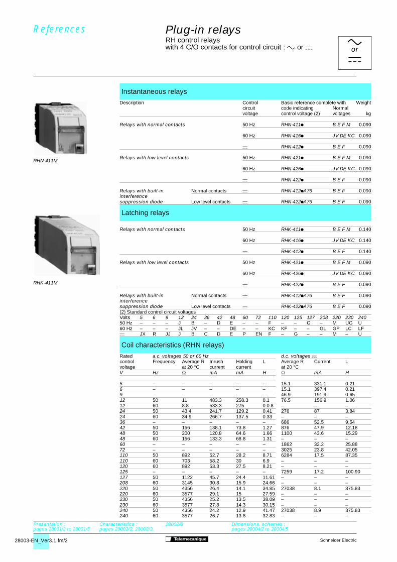
Plug-in relays RH control relayswith 4 C/O contacts for control circuit : a or c
Instantaneous relays
Description Control Basic reference complete with Weightcircuit code indicating Normalvoltage control voltage (2) voltages kg
Relays with normal contacts 50 Hz RHN-411p B E F M 0.090
60 Hz RHN-416p JV DE KC 0.090
c RHN-412p B E F 0.090
Relays with low level contacts 50 Hz RHN-421p B E F M 0.090
60 Hz RHN-426p JV DE KC 0.090
c RHN-422p B E F 0.090
Relays with built-in Normal contacts c RHN-412pA76 B E F 0.090interferencesuppression diode Low level contacts c RHN-422pA76 B E F 0.090
Latching relays
Relays with normal contacts 50 Hz RHK-411p B E F M 0.140
60 Hz RHK-416p JV DE KC 0.140
c RHK-412p B E F 0.140
Relays with low level contacts 50 Hz RHK-421p B E F M 0.090
60 Hz RHK-426p JV DE KC 0.090
c RHK-422p B E F 0.090
Relays with built-in Normal contacts c RHK-412pA76 B E F 0.090interferencesuppression diode Low level contacts c RHK-422pA76 B E F 0.090(2) Standard control circuit voltagesVolts 5 6 9 12 24 36 42 48 60 72 110 120 125 127 208 220 230 24050 Hz – – – J B – D E – – F – – G – M UG U60 Hz – – – JL JV – – DE – – KC KF – – GL GP LC LFc JX R JJ J B C D E P EN F – G – – M – U
Coil characteristics (RHN relays)
Rated a.c. voltages 50 or 60 Hz d.c. voltages ccontrol Frequency Average R Inrush Holding L Average R Current Lvoltage at 20 °C current current at 20 °CV Hz mA mA H mA H
5 – – – – – 15.1 331.1 0.216 – – – – – 15.1 397.4 0.219 – – – – – 46.9 191.9 0.6512 50 11 483.3 258.3 0.1 76.5 156.9 1.0612 60 8.8 533.3 275 0.0.8 – – –24 50 43.4 241.7 129.2 0.41 276 87 3.8424 60 34.9 266.7 137.5 0.33 – – –36 – – – – – 686 52.5 9.5442 50 156 138.1 73.8 1.27 876 47.9 12.1848 50 200 120.8 64.6 1.66 1100 43.6 15.2948 60 156 133.3 68.8 1.31 – – –60 – – – – – 1862 32.2 25.8872 – – – – – 3025 23.8 42.05110 50 892 52.7 28.2 8.71 6284 17.5 87.35110 60 703 58.2 30 6.9 – – –120 60 892 53.3 27.5 8.21 – – –125 – – – – – 7259 17.2 100.90127 50 1122 45.7 24.4 11.61 – – –208 60 3145 30.8 15.9 24.66 – – –220 50 4356 26.4 14.1 34.85 27038 8.1 375.83220 60 3577 29.1 15 27.59 – – –230 50 4356 25.2 13.5 38.09 – – –230 60 3577 27.8 14.3 30.15 – – –240 50 4356 24.2 12.9 41.47 27038 8.9 375.83240 60 3577 26.7 13.8 32.83 – – –
Referencesaorc
RHN-411M
RHK-411M
Presentation : pages 28001/2 to 28001/5
Characteristics : pages 28002/2, 28002/3,
28002/8 Dimensions, schemes :pages 28004/2 to 28004/5

28003-EN_Ver3.1.fm/3Schneider Electric
Plug-in relays RH control relayswith 4 C/O contacts for control circuit : a or c
Time delay relays - On-delay (1)
Description Control Timing Basic reference complete Weightcircuit range with code indicating Normalvoltage control voltage (2) voltages kg
Relays with 12…127 V (3) 0.2…300 s RHT-418p B E F 0.130normal contacts 50 Hz, 60 Hz, c
1.25 s…40 min RHT-4138p B E F 0.130
220 V, 240 V 0.2…300 s RHT-411p M 0.13050 Hz, 60 Hz
1.25 s…40 min RHT-4131p M 0.130
Relays with 12…127 V (3) 0.2…300 s RHT-428p B E F 0.130low level contacts 50 Hz, 60 Hz, c
1.25 s…40 min RHT-4238p B E F 0.130
220 V. 240 V 0.2…300 s RHT-421p M 0.13050 Hz, 60 Hz
1.25 s…40 min RHT-4231p M 0.130
Time delay relays - Off-delay (1)
Relays with 12…127 V (3) 0.2…300 s RHR-418p B E F 0.130normal contacts 50 Hz, 60 Hz, c
1.25 s…40 min RHR-4138p B E F 0.130
220 V, 240 V 0.2…300 s RHR-411p M 0.13050 Hz, 60 Hz
1.25 s…40 min RHR-4131p M 0.130
Relays with 12…127 V (3) 0.2…300 s RHR-428p B E F 0.130low level contacts 50 Hz, 60 Hz, c
1.25 s…40 min RHR-4238p B E F 0.130
220 V, 240 V 0.2…300 s RHR-421p M 0.13050 Hz, 60 Hz
1.25 s…40 min RHR-4231p M 0.130
(1) Relay fitted with interference suppression coil with built-in diode.(2) Standard control circuit voltages.Volts 12 24 42 48 60 72 110 125 127 220 24050 Hz, 60 Hz and c J B D E P EN F G G – –50 Hz and 60 Hz – – – – – – – – – M U(3) These products will not operate on a 12 V.
References
RHT-418E
Presentation : pages 28001/2 to 28001/5
Characteristics : pages 28002/4. 28002/5,
28002/8 and 28002/9 Dimensions, schemes :pages 28004/2 to 28004/5
aorc

28003-EN_Ver3.1.fm/4 Schneider Electric
Plug-in relays RH type PLC relayswith 4 C/O contacts for control circuit a or c current
Pulse on energisation relays (200 ms) (1)
Description Control Basic reference complete Weightcircuit with code indicating Normalvoltage control voltage (2) voltages kg
On energisation
Relays with 12…127 V (3) RHE-418p B E F 0.130normal contacts 50 Hz, 60 Hz, c
220 V, 240 V RHE-411p M 0.13050 Hz, 60 Hz
Relays with 12…127 V (3) RHE-428p B E F 0.130low level contacts 50 Hz, 60 Hz, c
220 V, 240 V RHE-421p M 0.13050 Hz, 60 Hz
On de-energisation
Relays with 12…127 V (3) RHD-418p B E F 0.130normal contacts 50 Hz, 60 Hz, c
220 V, 240 V RHD-411p M 0.13050 Hz, 60 Hz
Relays with 12…127 V (3) RHD-428p B E F 0.130low level contacts 50 Hz, 60 Hz, c
220 V, 240 V RHD-421p M 0.13050 Hz, 60 Hz
Flashing relays (adjustable symmetrical flashing time) (1)
Description Control Basic reference complete Weightcircuit with code indicating Normalvoltage control voltage (2) voltages kg
Relays with 12…127 V (3) 0.5…5 s RHC-418p B E F 0.130normal contacts 50 Hz, 60 Hz, c
2…30 s RHC-4198p B E F 0.130
220 V, 240 V 0.5…5 s RHC-411p M 0.13050 Hz, 60 Hz
2…30 s RHC-4191p M 0.130
(1) Relay fitted with interference suppression coil with built-in diode.(2) Standard control circuit voltages.Volts 12 24 42 48 60 72 110 125 127 220 24050 Hz, 60 Hz and c J B D E P EN F G G – –50 Hz and 60 Hz – – – – – – – – – M U(3) These products will not operate on a 12 V.
References (continued)
RHC-418E
RHE-418E
Presentation : pages 28001/2 to 28001/5
Characteristics : pages 28002/4, 28002/5,
28002/7 and 28002/8 Dimensions, schemes :pages 28004/2 to 28004/5
aorc

28003-EN_Ver3.1.fm/5Schneider Electric
Accessories for back wiring
Description Sold Unit Weightin referencelots of kg
Sockets With 2.8 x 0.5 mm tag for 10 RHZ-11 0.020(Markable soldering or Faston connectorswith3 ABR With 0.8 x 1.6 x 22 mm pins 10 RHZ-12 0.020clip-in for wire wrap or termi-pointcharacters)
With 0.8 x 0.8 x 4.3 mm solder 10 RHZ-13 0.020pins on 7.62 mm centres
Adaptor Back : 4 tags 2.8 x 0.5 mm 1 RHZ-15 0.0254 terminals and 4 pins 0.6 x 1.6 x 22 mmfor "back-front" Front : 4 screw terminals for 2 x 2.5 mm2
connection wires
Hinged For 12 sockets or adaptors 1 RHZ-70 0.450modularChassis For 21 sockets or adaptors 1 RHZ-71 0.500suppliedin kit form For 30 sockets or adaptors 1 RHZ-72 0.600
For 36 sockets or adaptors 1 RHZ-73 0.650(on 19 inch chassis)
Cable For mounting on hinged chassis 10 RHZ-68 0.010clip
Accessories for front wiring
Sockets Screw terminals 1 RHZ-21 0.100(Protected for 2 x 2.5 mm2 wiresagainst directfinger contact With double tags 2.8 x 0.5 1 RHZ-22 0.080and markable for Faston connectorswith 4 AB1clip-in With double tags 4.8 x 0.8 1 RHZ-24 0.085characteristics) for Faston connectors
Socket For making up a sequence 1 RHZ-42 0.080integratedwiring
Termination Top connectors : 4 tags 2.8 x 0.5 mm 1 RHZ-25 0.040adaptor and 4 pins 0.8 x 1.6 x 22 mm4 terminals for Bottom connection : 4 screw terminals (protected againstfront-back" direct finger contact) for 2 x 2.5 mm2 wiresconnection
Mounting For mounting sockets and 10 RHZ-66 0.005adaptor termination adaptors on 4 rail
Accessories for suppressors and for marking
Accessories RC suppressor With flexible cable 10 RHZ-32 0.008forsuppressors for relays
12…220 V With rigid cable 10 RHZ-33 0.008
Accessories Self-adhesive Pack of 1 RHZ-63 0.010for labels 7 x 13 mm 980 labelsmarking
Clip-in Strips of 10 25 AB1-Rp (1) 0.002characters identical numbers identical(3 or 4 maximum) from 0 to 9 strips
Strips of 10 25 AB1-Gp (1) 0.002identical capital identicalletters A to Z strips
(1) To order, replace the • in the reference with the required character.
Plug-in relays RH type PLC relaysAccessories
References
RHZ-15
RHZ-21
RHZ-66
RHZ-11
RHZ-71
RHZ-68
Presentation : pages 28001/2 to 28001/5
Characteristics : pages 28002/6 and 28002/7
Dimensions, schemes :pages 28004/2 to 28004/5
8004 Ver3.00-EN.fm/2 Schneider Electric
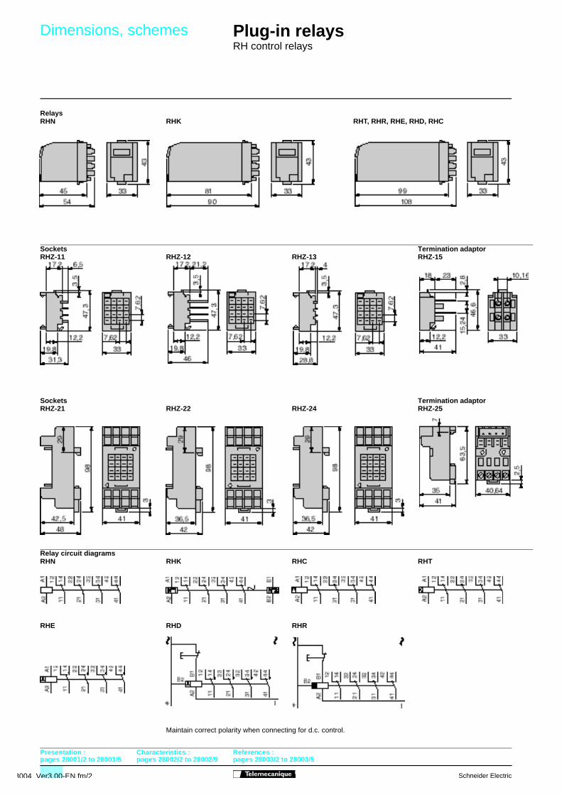
Plug-in relays RH control relays
RelaysRHN RHK RHT, RHR, RHE, RHD, RHC
Sockets Termination adaptorRHZ-11 RHZ-12 RHZ-13 RHZ-15
Sockets Termination adaptorRHZ-21 RHZ-22 RHZ-24 RHZ-25
Relay circuit diagramsRHN RHK RHC RHT
RHE RHD RHR
Maintain correct polarity when connecting for d.c. control.
Dimensions, schemes
Presentation :pages 28001/2 to 28001/5
Characteristics : pages 28002/2 to 28002/9
References : pages 28003/2 to 28003/5

28004 Ver3.00-EN.fm/Schneider Electric
Plug-in relays RH control relaysSockets and termination adaptors for front wiring
RHZ-42Panel mounted
Sockets Clipped directly Clipped onto one DZ5-MB railRHZ-21 RHZ-22, RHZ-24 onto one AM1-DP rail using adaptor RHZ-66Panel mounted Panel mounted
With relay RHN RHK RHT RHR RHE RHD RHCc 82 118 136 136 136 136 136c1 95 131 149 149 149 149 149(1) 110 min
Termination adaptor Clipped directly Clipped onto one DZ5-MB railRHZ-25 onto one AM1-DP rail using adaptor RHZ-66Panel mounted
Mounting the relay on the socketInstant clip-in locking Release by pressing tabs
Mounting
Presentation :pages 28001/2 to 28001/5
Characteristics :pages 28002/6 to 28002/7
References :page 28004/5

8004 Ver3.00-EN.fm/4 Schneider Electric
on slotted plate
Mounting directly on hinged modular chassis RHZ-7p
(1) modular 183
Sockets Termination adaptorRHZ-11 RHZ-12 RHZ-15
Mounted directly Plate cut-out
e : 1 mm (min) to 2 mm (max) e (1) 1 mm 2 mm
With relays RHN RHK RHT to RHC H 35.7 ±0.15 36.7 ±0.15c 57 93 111 (1) plate thickness
RHZ-70 RHZ-71 RHZ-72 RHZ-73a 215 315 415 480a1 155 255 355 420G 200 300 400 465
Presentation :pages 28001/2 to 28001/5
Characteristics :pages 28002/6 to 28002/7
References :page 28003/5
Chassis supporthinge
Cross-section
Plug-in relays RH control relaysSockets and termination adaptors for back wiring
Mounting

28004 Ver3.00-EN.fm/Schneider Electric
RHZ-13
Mounting on printed circuit board
Socket
Plug-in relaysRH control relaysSockets and termination adaptors for back wiring
Mounting
Presentation :pages 28001/2 to 28001/5
Characteristics :pages 28002/6 to 28002/7
References :page 28003/5
1.8 conductor
Ø 2.5 solder padØ 1.3 hole
On all printed circuit boards with pin spacing of 2.54 mm.The 7.62 mm spacing between pins (3 x 2.54 mm) allows space between rows of pins for a 1.8 mm x 70 m conductor with a capacity of 5 A at 240 V a
Socket mounting