Present Status of HBC Stripper Foil...
49
Present Status of HBC Stripper Foil Development Y.Takeda a , M.Oyaizu a , H.Kawakami a , Y.Irie a ,A.Takagi a , HH tt i b KK ki b By Isao.Sugai a , H.Hattori b , K.Kawasaki b T.Spickermann c a) High Energy Accelerator Research Organization (KEK b) Tokyo Institute of Technology c) Los Alamos National Laboratory
Transcript of Present Status of HBC Stripper Foil...
Present Status of HBC Stripper Foil ppDevelopment
Y.Takedaa, M.Oyaizua, H.Kawakamia, Y.Iriea,A.Takagia, H H tt ib K K kib
By Isao.Sugaia,
H.Hattorib, K.KawasakibT.Spickermannc
a) High Energy Accelerator Research Organization (KEK
b) Tokyo Institute of Technologyc) Los Alamos National Laboratory
Talk;
■ Requirement of Stripper Foil for RCS of
Talk;
J-PARC Accelerator
■ Brief history of carbon foil developments
■ Limits of Cluster Carbon Foils made by CADAD MethodMethod
■ Development of HBC-Foils
■ Lifetime Measurements of HBC, Diamond and CM-Foils by using 3.2 MeV Ne+, 650KeV H- and 800MeV
H- Ion Beams■ Summary and Conclusions

Schematic view of J-PARCH drHadron Experimental Facility
Materials and Life S i E i t lScience Experimental
Facility
500m!
Neutrino Experimental Facility
Linac(340m)
3-GeV RCS-Ring(25Hz,1MW)
(340m)50-GeV-Ring(0.75MW)

Schematic layout of the Accelerator Complex ofJ-PARC and Stripper Foil Position

Injection Beam and Stripper Foil Properties of 3GeV ring at J-PARC
Kinetic energy 200 MeV (first stage)400 MeV (second stage)
Beam pulse length 0.5 msRepetition rate 25HzpAverage beam current 0.333mABeam Size 10 mm x 10 mmFoil thickness 200-400 μg/cm2
Foil peak temperature ; >1800K(If average foil hitting number of bunched proton is >17 and
Circulating bunched beam is 8.3x 10¹³/bunch )
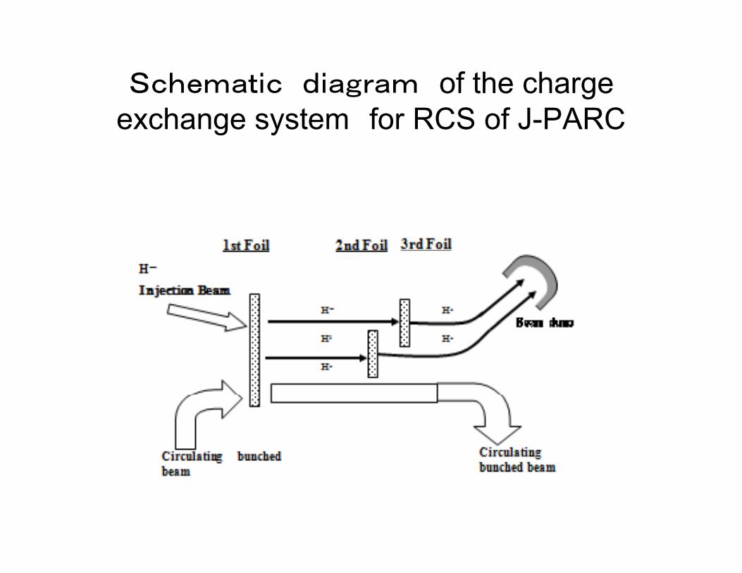
Schematic diagram of the charge exchange system for RCS of J-PARC
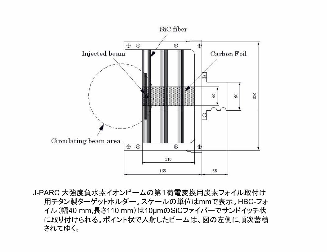
J-PARC 大強度負水素イオンビームの第1荷電変換用炭素フォイル取付け用チタン製ターゲットホルダー。スケールの単位はmmで表示。HBC-フォイル(幅40 mm,長さ110 mm)は10μmのSiCファイバーでサンドイッチ状
に取り付けられる。ポイント状で入射したビームは、図の左側に順次蓄積されてゆく。
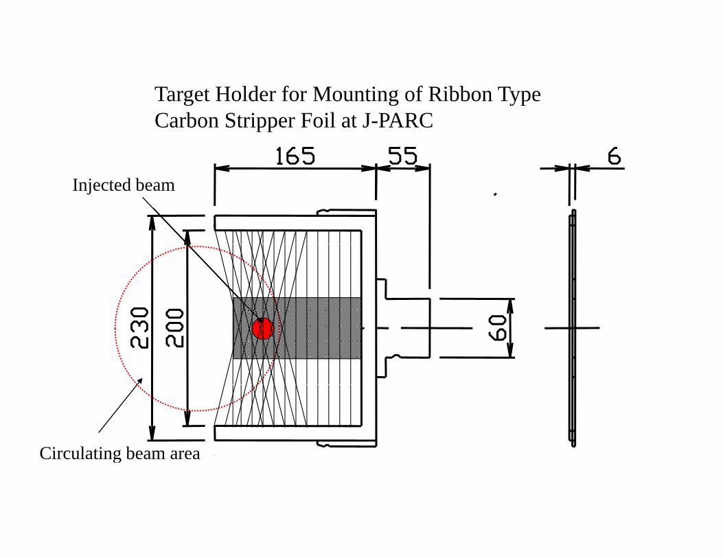
Target Holder for Mounting of Ribbon Typeg g ypCarbon Stripper Foil at J-PARC
Injected beam
Circulating beam areaCirculating beam area
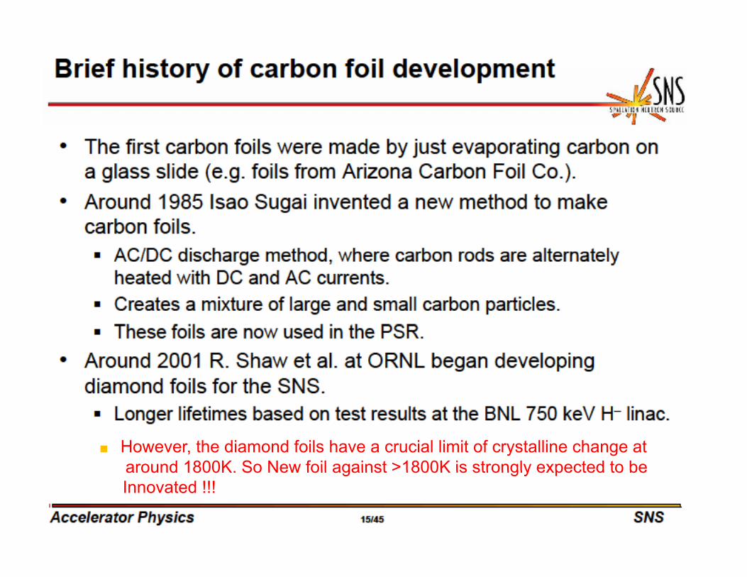
■ However, the diamond foils have a crucial limit of crystalline change at around 1800K So New foil against >1800K is strongly expected to bearound 1800K. So New foil against >1800K is strongly expected to be Innovated !!!
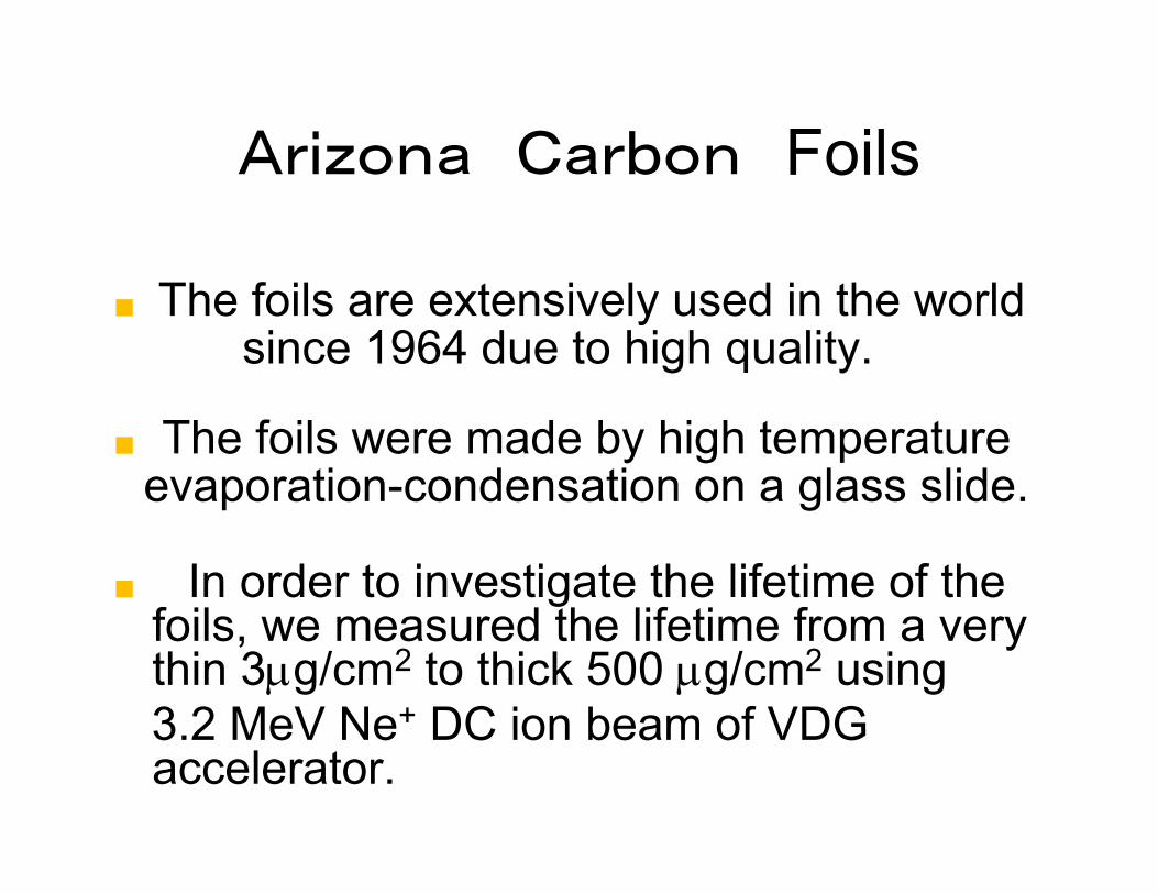
Arizona Carbon FoilsArizona Carbon Foils
■ The foils are extensively used in the worldsince 1964 due to high quality.
■ The foils were made by high temperatureevaporation-condensation on a glass slide.p g
■ In order to investigate the lifetime of the foils e meas red the lifetime from a erfoils, we measured the lifetime from a very thin 3μg/cm2 to thick 500 μg/cm2 using3 2 MeV Ne+ DC ion beam of VDG3.2 MeV Ne DC ion beam of VDG accelerator.
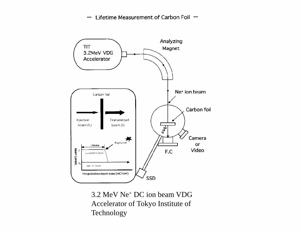
3.2 MeV Ne+ DC ion beam VDG Accelerator of Tokyo Institute of Technology
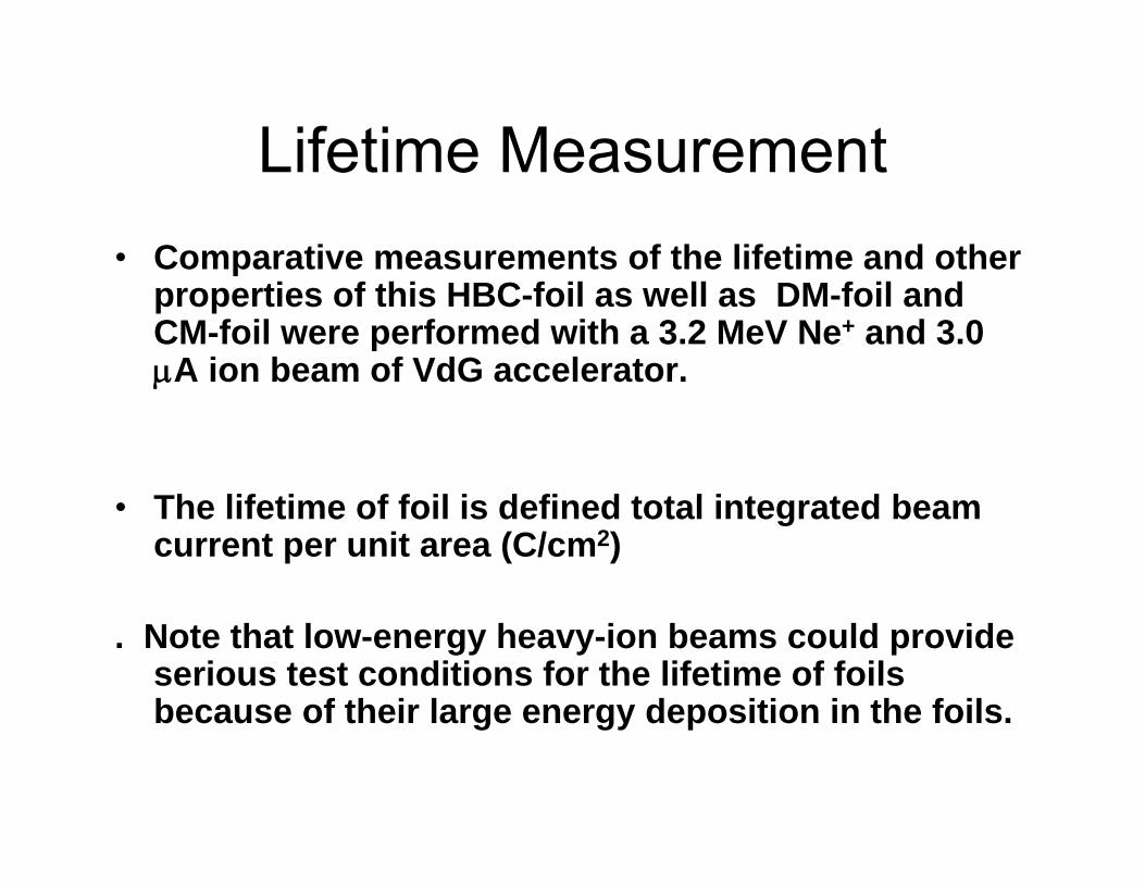
Lifetime MeasurementLifetime Measurement• Comparative measurements of the lifetime and other p
properties of this HBC-foil as well as DM-foil and CM-foil were performed with a 3.2 MeV Ne+ and 3.0 μA ion beam of VdG accelerator.μ
Th lif ti f f il i d fi d t t l i t t d b• The lifetime of foil is defined total integrated beam current per unit area (C/cm2)
. Note that low-energy heavy-ion beams could provide serious test conditions for the lifetime of foils because of their large energy deposition in the foils.because of their large energy deposition in the foils.
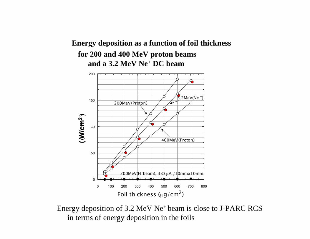
Energy deposition as a function of foil thicknessEnergy deposition as a function of foil thicknessfor 200 and 400 MeV proton beams
and a 3.2 MeV Ne+ DC beam200
150
200
3.2MeV(Ne +)200MeV(Proton)
100
W/c
m2 )
200MeV(Proton)
W/c
m2
)
50
(W 400MeV(Proton)( W
0
0 100 200 300 400 500 600 700 800
Foil thickness (μg/cm2)
200MeV(H -beam), 333 μA /10mmx10mm
Energy deposition of 3.2 MeV Ne+ beam is close to J-PARC RCSin terms of energy deposition in the foils
Foil thickness (μg/cm )

Arizona Carbon Foils fromArizona Carbon Foils from 1μg/cm2 to 500 μg/cm2
Lifetime versus Foil thickness (CM-Foils)

Arizona Foils were found to beArizona Foils were found to be“very short lifetime”
So, we developed a new cluster foil by , p yControlled AC/DC arc
Discharge method (CADAD)Discharge method (CADAD).
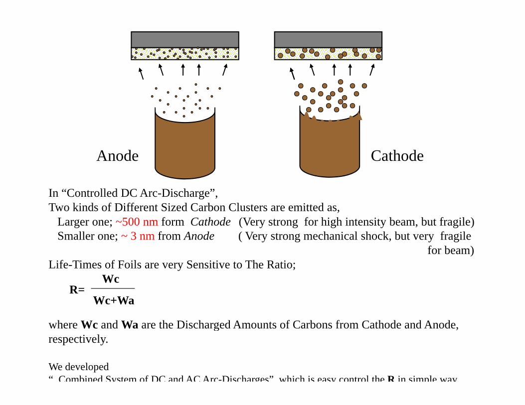
Anode Cathode
In “Controlled DC Arc-Discharge”,Two kinds of Different Sized Carbon Clusters are emitted as,
Larger one; ~500 nm form Cathode (Very strong for high intensity beam, but fragile)Smaller one; ~ 3 nm from Anode ( Very strong mechanical shock, but very fragile
for beam)Life-Times of Foils are very Sensitive to The Ratio;
WcWcR=
Wc+Wa
where Wc and Wa are the Discharged Amounts of Carbons from Cathode and Anode, g ,respectively.
We developed “ Combined System of DC and AC Arc-Discharges” which is easy control the R in simple way

CathodeDC arc-discharge
Anode AC arc-DischargeAnode
DC and AC arc-discharge geometries for Cluster foil tipreparation

Cluster foils on Side GlassCluster foils on Side Glass
■ R=>50%
( R / + )( R= wc / wc + wa)
■ Max,accessible foil thicknessfoil thickness
■ 130±40 μg/cm2
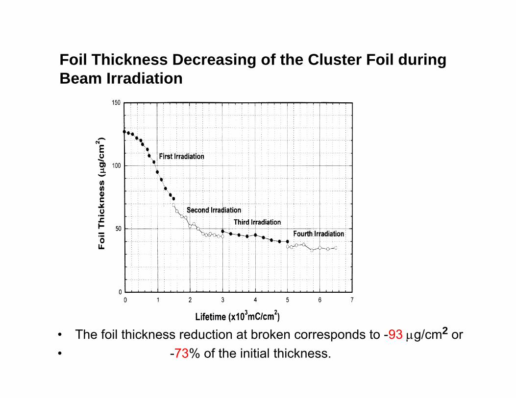
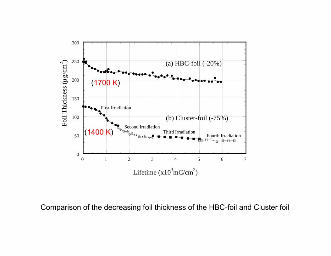
Foil Thickness Decreasing of the Cluster Foil during B I di tiBeam Irradiation
• The foil thickness reduction at broken corresponds to -93 μg/cm2 or • -73% of the initial thickness.

In order to overcome these problems
■ We have tried to mix the graphite rod with foreign atoms like Be,B, Al, Si, etcg
■ Among these, the boron-mixed foil showed especially good results.
■ Here, Stripper foils made by this method, which we can Hybrid Boron mixed Carbon stripper foil
( HBC-foil)
Discovery of HBC-foilDiscovery of HBC foil
I d h blIn order to overcome these problems
■ We have tried to mix the graphite rod with foreign■ We have tried to mix the graphite rod with foreign
atoms like Be, B, Al, Si, etc.A h h b i d f il h d i ll■ Among these, the boron-mixed foil showed especially
good results.■ Here Stripper foils made by this method which we can■ Here, Stripper foils made by this method, which we can
Hybrid Boron mixed Carbon stripper foil( HBC-foil)( C o )

Anode of B(20%)B(20%)
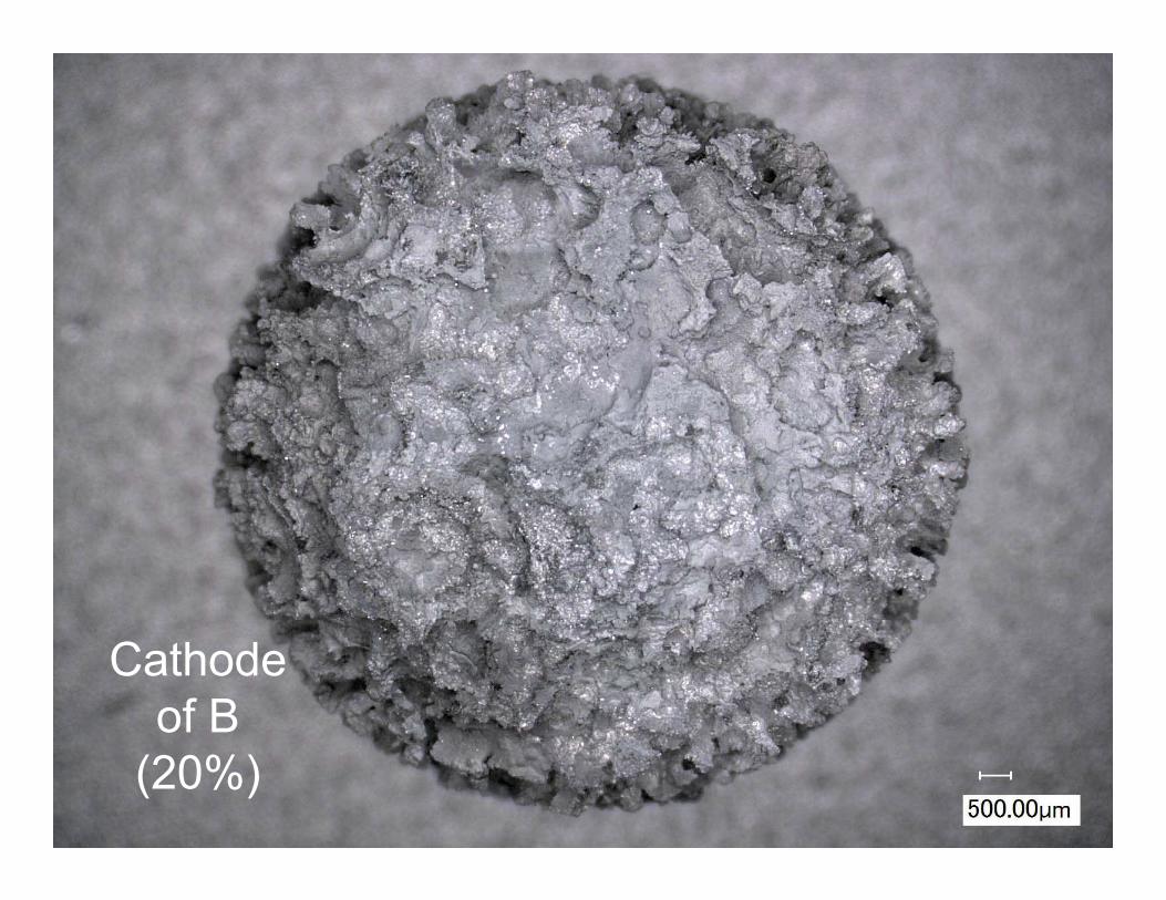
Cathode of B
(20%)
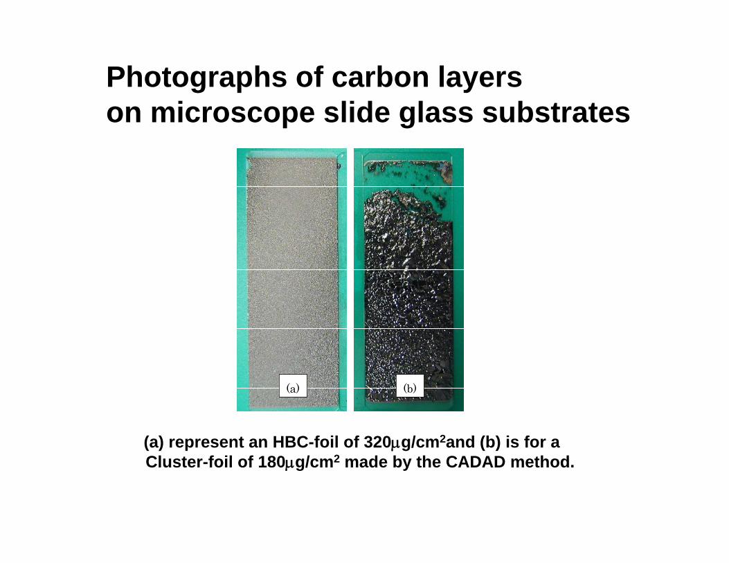
Photographs of carbon layers i lid l b t ton microscope slide glass substrates
(a) (b)
(a) represent an HBC-foil of 320μg/cm2and (b) is for a Cluster foil of 180 g/cm2 made by the CADAD method
(a) (b)
Cluster-foil of 180μg/cm2 made by the CADAD method.

Large area HBC-Foil( FNAL-09/11/12)
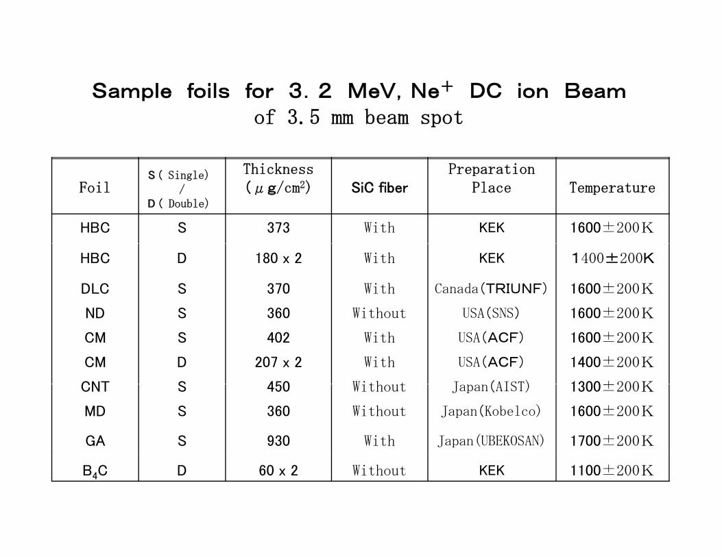
Sample foils for 3.2 MeV,Ne+ DC ion Beamof 3.5 mm beam spot
S ( Si l ) Thickness PreparationFoil
S ( Single)/
Thickness(μg/cm2) SiC fiber
Preparation Place Temperature
D ( Double)
HBC S 373 With KEK 1600±200K
HBC D 180 x 2 With KEK 1400±200K
DLC S 370 With Canada(TRIUNF) 1600±200K
ND S 360 Without USA(SNS) 1600±200KND S 360 Without USA(SNS) 1600±200K
CM S 402 With USA(ACF) 1600±200K
CM D 207 x 2 With USA(ACF) 1400±200K
CNT S 450 With t J (AIST) 1300±200KCNT S 450 Without Japan(AIST) 1300±200K
MD S 360 Without Japan(Kobelco) 1600±200K
GA S 930 With Japan(UBEKOSAN) 1700±200K
B4C D 60 x 2 Without KEK 1100±200K

Photos of HBC
(a)SNS/ORNL-ND-foil: Before (250mC/cm2) After (610mC/cm2)
Photos of HBC,SNS-DM,CM foilsat different stage
of3.2 MeV Ne+
Irradiation(b)ACF-foil: Before (5mC/cm2) After (15 mC/cm2)
Irradiation
(c)Kobelco-MD: Before (60mC/cm2) After(120mC/cm2)
(d)KEK:S-HBC-Before (35000mC/cm2) After(8500 mC/cm2 )
300
200
250μg
/cm
2 ) (a) HBC-foil (-20%)
150
200
Thic
knes
s (μ
First Irradiation
(1700 K)
50
100
Foil
T
(b) Cluster-foil (-75%)Second Irradiation
Third IrradiationFourth Irradiation(1400 K)
00 1 2 3 4 5 6 7
Lifetime (x103mC/cm2)
Comparison of the decreasing foil thickness of the HBC-foil and Cluster foilComparison of the decreasing foil thickness of the HBC foil and Cluster foil

ACF-foil
フォ
SNS-ND-foil
DLC-foil
ォイル名
Kobelco-MD-foil
AIST-CNT-foil
S-HBC-foil
D-HBC-foil
0 2.5 5.0 7.5 10.0 12.5 15.0Lifetime(C/cm2)
Lifetime results of various foils measured with3 2 M V N + i B f 3 0 A 3 5 Φ
Lifetime(C/cm )
a 3.2 MeV, Ne+ ion Beam of 3.0 μA on 3.5 mm Φ
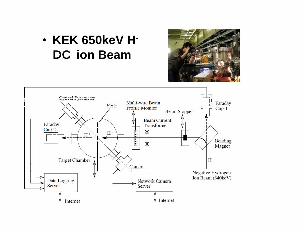
• KEK 650keV H-KEK 650keV HDC ion Beam
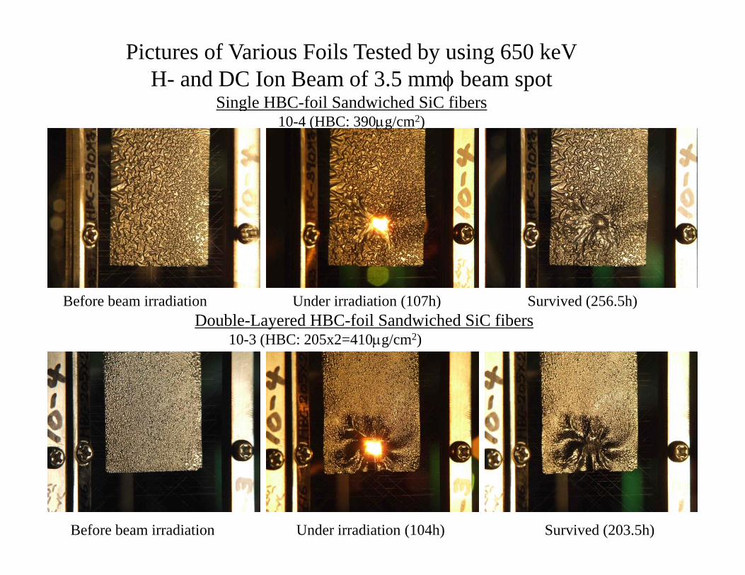
Pictures of Various Foils Tested by using 650 keVH- and DC Ion Beam of 3.5 mmφ beam spot
Single HBC-foil Sandwiched SiC fibersSingle HBC foil Sandwiched SiC fibers10-4 (HBC: 390μg/cm2)
Before beam irradiation Under irradiation (107h) Survived (256.5h)Double-Layered HBC-foil Sandwiched SiC fibersDouble Layered HBC foil Sandwiched SiC fibers
10-3 (HBC: 205x2=410μg/cm2)
Before beam irradiation Under irradiation (104h) Survived (203.5h)

Microcrystalline Diamond Sandwiched SiC fibers for SNSy3-2 (SNS #510: 383μg/cm2)
Before irradiation Under irradiation (6h) back bending (11h)
Irradiation after 3min Under irradiation (5.0h) back bending (14h)
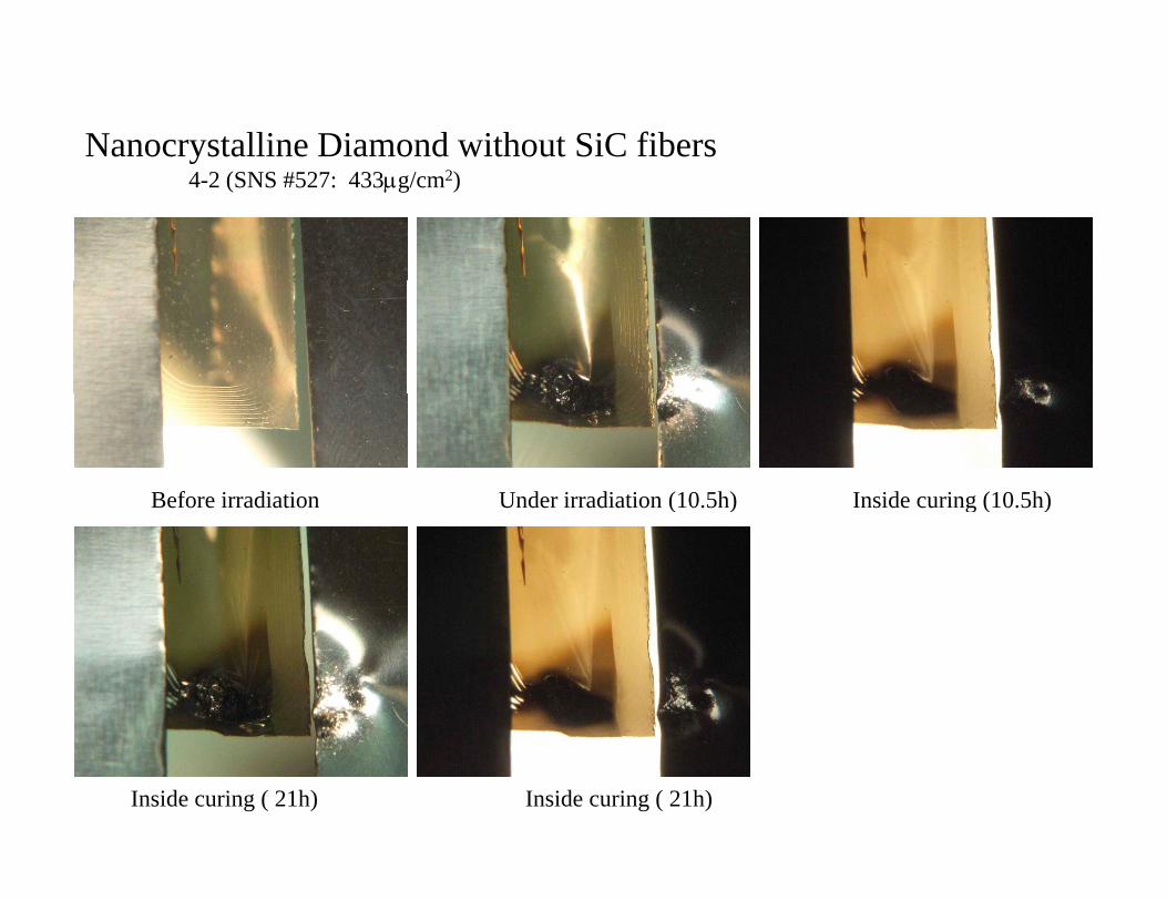
Nanocrystalline Diamond without SiC fibers4-2 (SNS #527: 433μg/cm2)
Before irradiation Under irradiation (10.5h) Inside curing (10.5h)e o e ad at o U de ad at o ( 0.5 ) s de cu g ( 0.5 )
Inside curing ( 21h) Inside curing ( 21h)

Multi-layered DLC for TRIUMFMulti layered DLC for TRIUMF8-5 (TRIUMF Multi-layered DLC: 2.3μm/ 480μg/cm2)
B f i di ti U d i di ti (0 5h) B k (1h)Before irradiation Under irradiation (0.5h) Broken (1h)
Surface image in dark
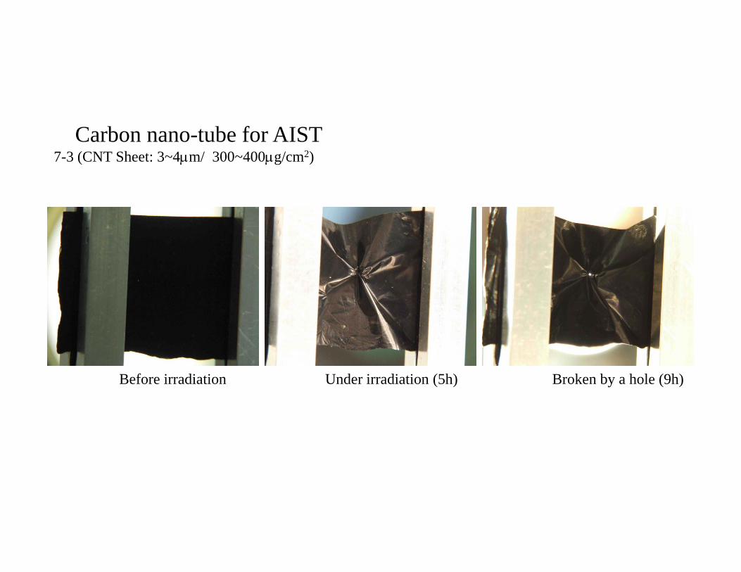
Carbon nano-tube for AIST7-3 (CNT Sheet: 3~4μm/ 300~400μg/cm2)
Before irradiation Under irradiation (5h) Broken by a hole (9h)
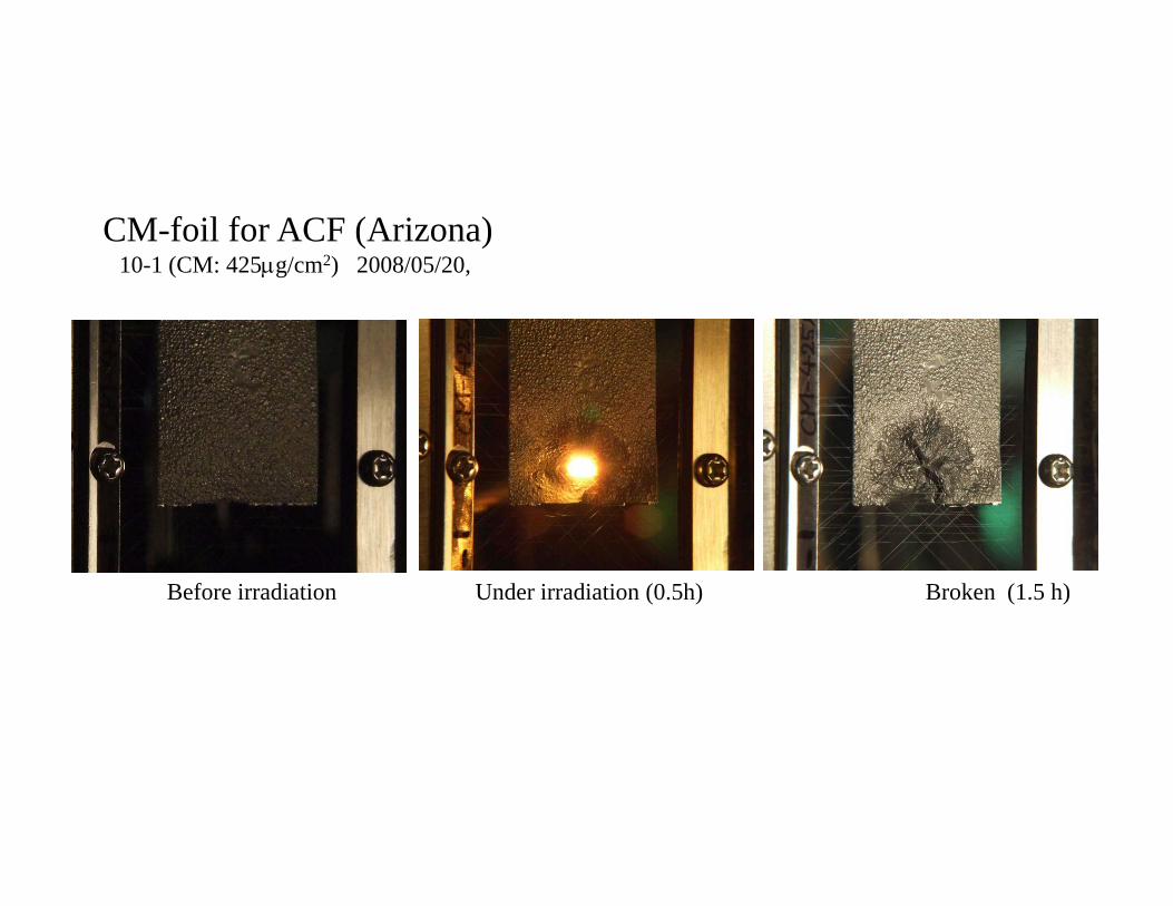
CM-foil for ACF (Arizona)10-1 (CM: 425μg/cm2) 2008/05/20,
Before irradiation Under irradiation (0.5h) Broken (1.5 h)
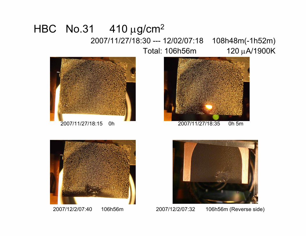
HBC No.31 410 μg/cm2
2007/11/27/18:30 --- 12/02/07:18 108h48m(-1h52m)( )Total: 106h56m 120 μA/1900K
2007/11/27/18:15 0h 2007/11/27/18:35 0h 5m
2007/12/2/07:40 106h56m 2007/12/2/07:32 106h56m (Reverse side)
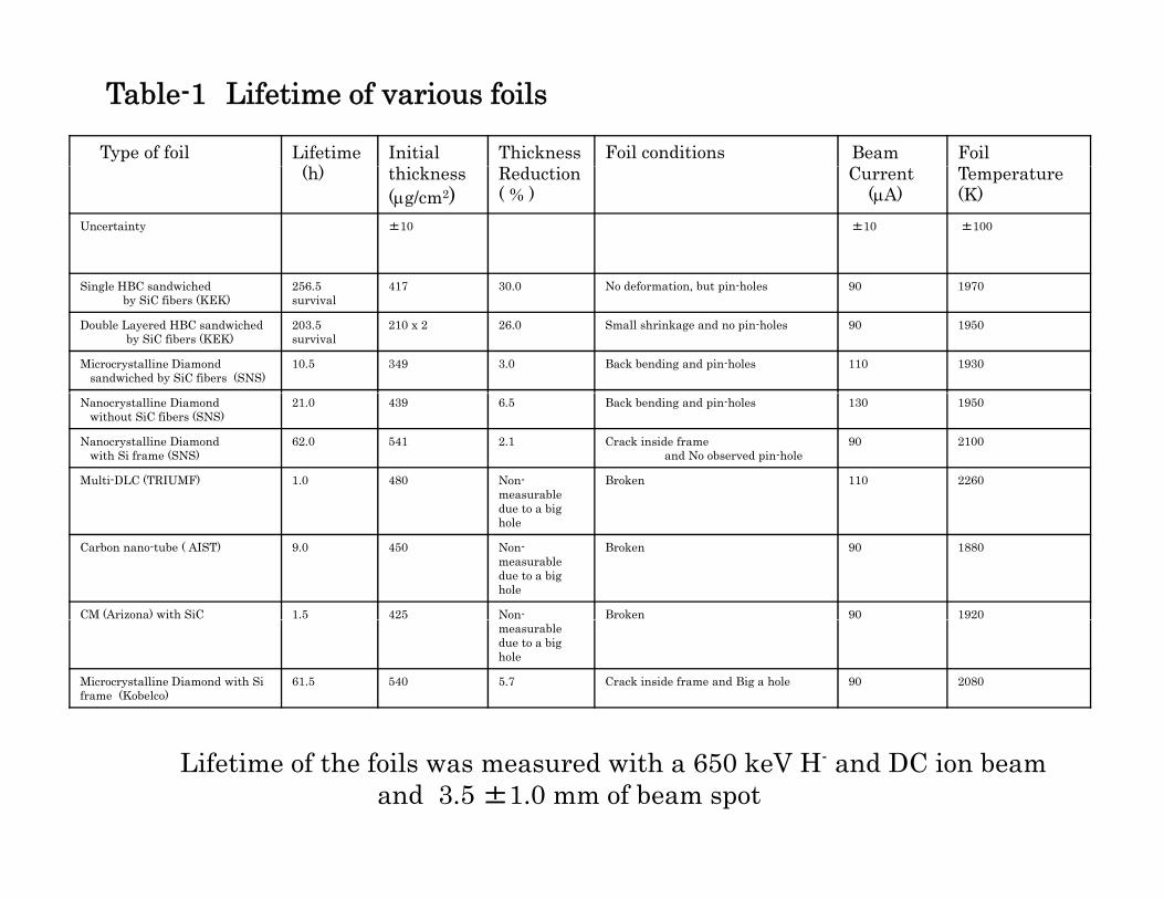
Table-1 Lifetime of various foils
Type of foil Lifetime( )
Initial Thickness Foil conditions Beam Foil(h) thickness
(μg/cm2)Reduction ( % )
Current(μA)
Temperature (K)
Uncertainty ±10 ±10 ±100
Single HBC sandwichedby SiC fibers (KEK)
256.5survival
417 30.0 No deformation, but pin-holes 90 1970
Double Layered HBC sandwiched by SiC fibers (KEK)
203.5survival
210 x 2 26.0 Small shrinkage and no pin-holes 90 1950
Microcrystalline Diamond sandwiched by SiC fibers (SNS)
10.5 349 3.0 Back bending and pin-holes 110 1930
Nanocrystalline Diamondwithout SiC fibers (SNS)
21.0 439 6.5 Back bending and pin-holes 130 1950
Nanocrystalline Diamondwith Si frame (SNS)
62.0 541 2.1 Crack inside frame and No observed pin-hole
90 2100
Multi-DLC (TRIUMF) 1.0 480 Non-measurable d t bi
Broken 110 2260
due to a big hole
Carbon nano-tube ( AIST) 9.0 450 Non-measurable due to a big hole
Broken 90 1880
CM (Arizona) with SiC 1.5 425 Non- Broken 90 1920measurable due to a big hole
Microcrystalline Diamond with Si frame (Kobelco)
61.5 540 5.7 Crack inside frame and Big a hole 90 2080
Lifetime of the foils was measured with a 650 keV H- and DC ion beamand 3.5 ±1.0 mm of beam spot

600
800
1000
(μg/
cm2 ) HBC-Foil: 417μg/cm2
Region
Iradiated by 650 keV H- ions3mm~
S-HBC-Foil:417μg/cm2
(- 30 %)
200
400Th
ickn
ess (
00 5 10 15 20 25
Relative distance (mm)
T
1000
) HBC F il 210 / 2 2
600
800
ss (μ
g/cm
2 ) HBC-Foil: 210μg/cm2x2
3mm~
Region
Iradiated by 650 keV H- ionsD-HBC-Foil:210μg/cm2x2
(-18 %)
200
400
Thic
knes
00 5 10 15 20 25
Relative distance (mm)
( The reduction in thickness of the HBC-foil )
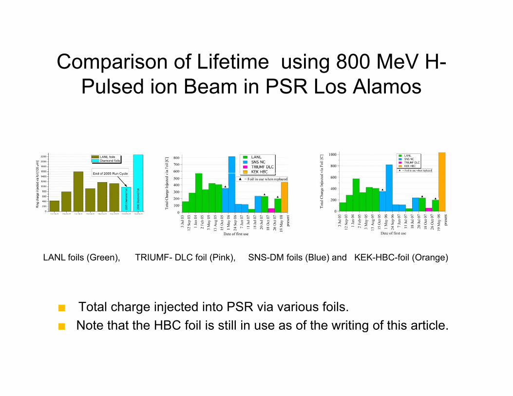
Comparison of Lifetime using 800 MeV H-Pulsed ion Beam in PSR Los Alamos
LANL foils (Green), TRIUMF- DLC foil (Pink), SNS-DM foils (Blue) and KEK-HBC-foil (Orange)
■ Total charge injected into PSR via various foils. Note that the HBC foil is still in use as of the writing of this article■ Note that the HBC foil is still in use as of the writing of this article.
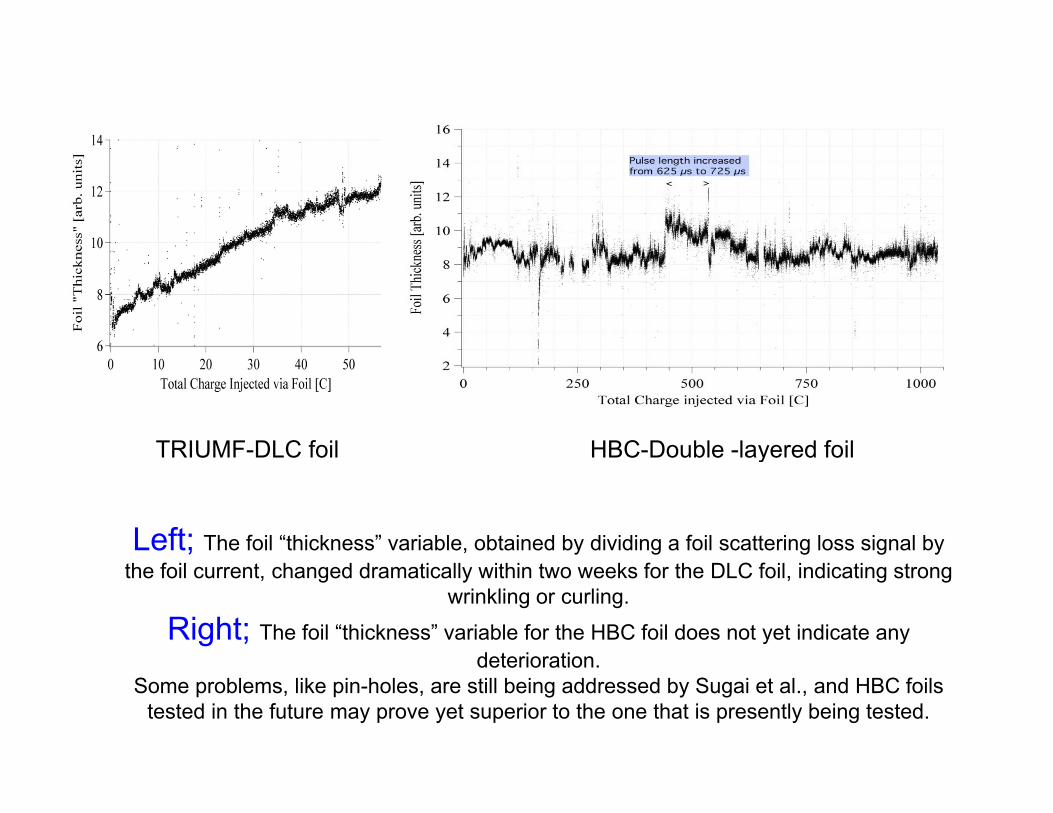
TRIUMF-DLC foil HBC-Double -layered foil
Left; The foil “thickness” variable, obtained by dividing a foil scattering loss signal by
y
the foil current, changed dramatically within two weeks for the DLC foil, indicating strong wrinkling or curling.
Right; The foil “thickness” variable for the HBC foil does not yet indicate any deteriorationdeterioration.
Some problems, like pin-holes, are still being addressed by Sugai et al., and HBC foils tested in the future may prove yet superior to the one that is presently being tested.
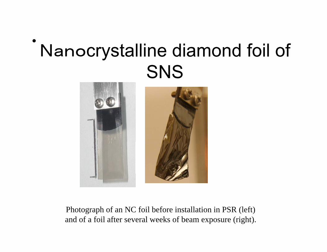
N t lli di d f il f•Nanocrystalline diamond foil of
SNS
Photograph of an NC foil before installation in PSR (left)and of a foil after several weeks of beam exposure (right).
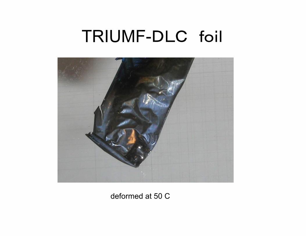
TRIUMF-DLC foil
deformed at 50 C
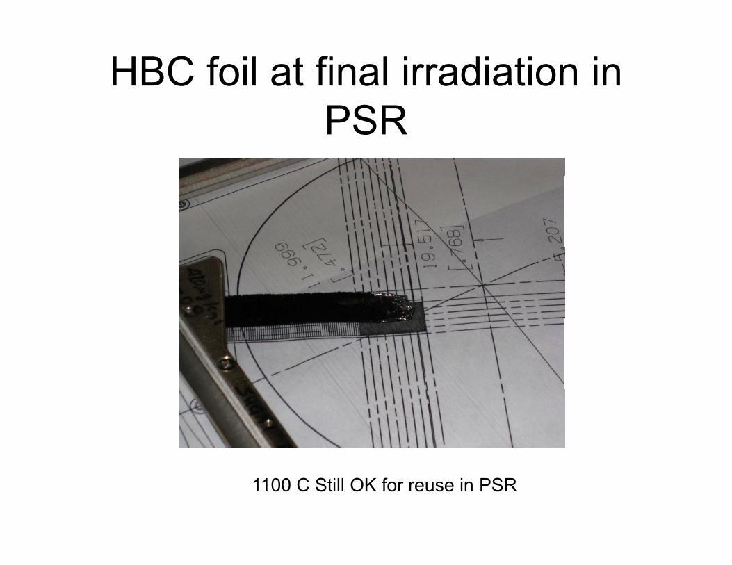
HBC foil at final irradiation in PSR
1100 C Still OK for reuse in PSR

Property of the HBC foilProperty of the HBC foil
in comparison withother forms of carbon Nano andother forms of carbon, Nano and Micro diamond, DLC and CNT
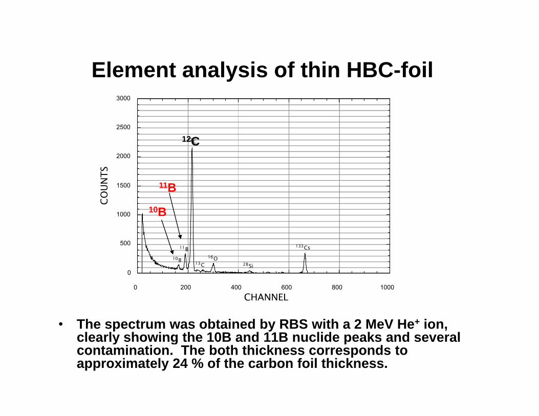
Element analysis of thin HBC-foilElement analysis of thin HBC foil
2500
3000
2000
NTS
12C12C
1000
1500
COUN
10B
11B
0
500
0 200 400 600 800 1000
10B
11B
13C16O
28Si
133Cs
• The spectrum was obtained by RBS with a 2 MeV He+ ion, clearly showing the 10B and 11B nuclide peaks and several
0 200 400 600 800 1000
CHANNEL
clearly showing the 10B and 11B nuclide peaks and several contamination. The both thickness corresponds to approximately 24 % of the carbon foil thickness.

Specific gravity, resistivity and thermal conductivity of HBC foil in comparison
with other forms of carbon
S ifi Th lSample
Specific gravity (g/cm3)
Resistivity(Ω・cm)
ThermalConductivity(w/m・k)
Single crystal of graphite 2.26
10-4perpendicularTo C-axis
Fine grain graphite
1.75-1.9 ~1 parallel toC-axis; 1.5-1.8 x 10⁻³
daiamond 3.5 > 1016 2000
Carbon nano-tube 4.7 × 10⁻⁴ 2000-4000
Boron 2.36 1.5 × 10⁶ 27.4
Boron carbide 2.51 0.5 20
Polygraphite 1.8-2.3 1.4 × 10⁻³ 50-130
ACF-foil 1.94 1.5 × 10⁻² 1.41
Cluster foil 1.85±0.20 1.26 3.95
HBC-foil 1.10 2.34 0.24
DLC-foil 2.5 >109 200

Raman Spectra of DM,CM and HBC-foilsRaman Spectra of DM,CM and HBC foils
0.8
1Data: Raman sp09.data 090526
Diamond (Non irrad.)
0.6
rb. u
nit] Diamond (irrad. by ion beam)
0.4Inte
nsity
[ar
Diamond (irrad. by laser)
0.2
HBC (Non irrad.)
Amorphous C (Irrad. by ion beam)
• The DM-foils are irradiated by ion beam and laser. The CM (amorphous)-foil is
0
1100 1200 1300 1400 1500 1600 1700
Raman Shift [cm-1]Raman sp.09jpeg2.fig
irradiated by only ion beam. In all irradiated foils, we can clearly see broad peaks at around 1580 and 1350 cm-1.
• The DM-foil irradiated by ion beam shows small peak at 1332cm-1, in contrast by laser irradiation.
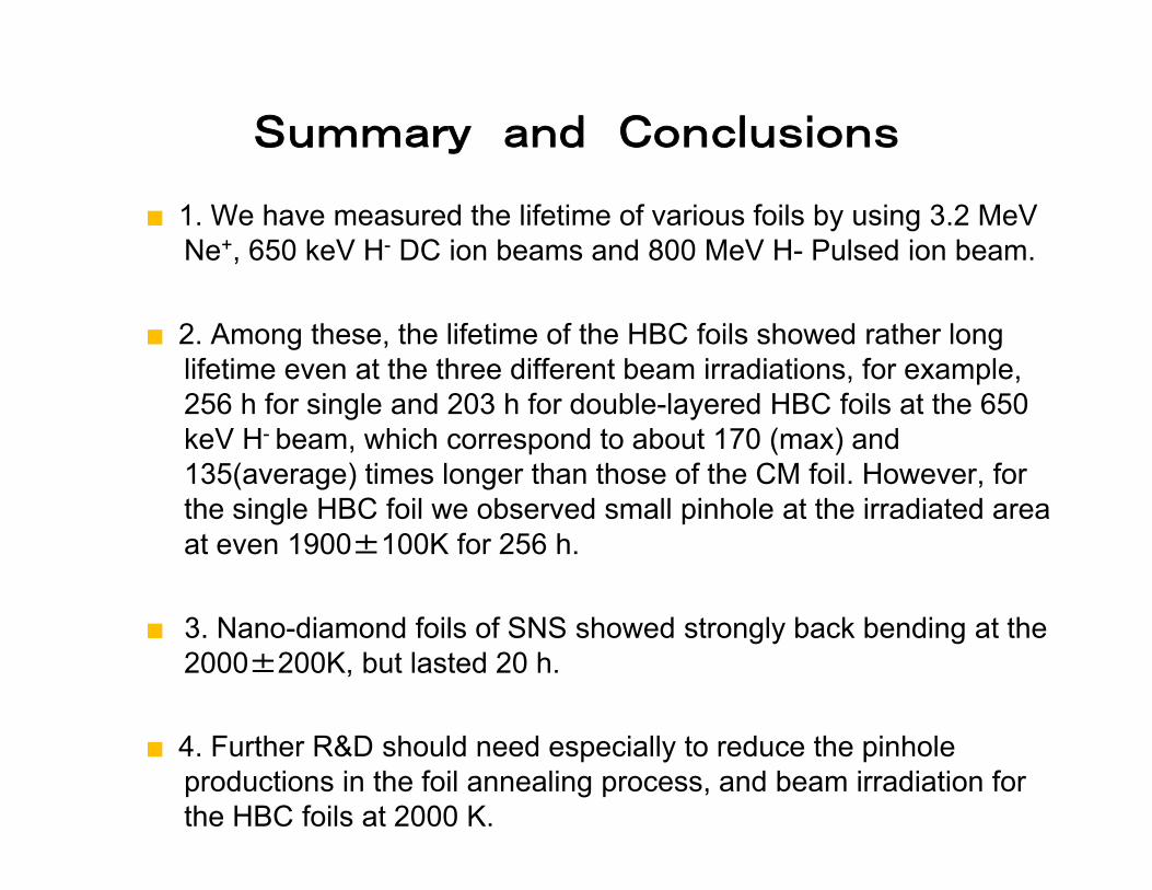
Summary and Conclusions
■ 1. We have measured the lifetime of various foils by using 3.2 MeV Ne+, 650 keV H- DC ion beams and 800 MeV H- Pulsed ion beam.
■ 2. Among these, the lifetime of the HBC foils showed rather long lifetime even at the three different beam irradiations, for example, 256 h for single and 203 h for double-layered HBC foils at the 650 keV H- beam, which correspond to about 170 (max) and 135(average) times longer than those of the CM foil. However, for th i l HBC f il b d ll i h l t th i di t dthe single HBC foil we observed small pinhole at the irradiated area at even 1900±100K for 256 h.
■ 3. Nano-diamond foils of SNS showed strongly back bending at the 2000±200K, but lasted 20 h.
■ 4. Further R&D should need especially to reduce the pinhole productions in the foil annealing process, and beam irradiation for the HBC foils at 2000 K.