prescribed torque. If the STC injectors have€¦ · STC Injector Adjustment (OBC Method): Torque...
16
Batteries can emit explosive gases. To reduce the possibility of personal injury, always ventilate the compartment before servicing the batteries. To reduce the possibility of arcing, remove the negative (-) battery cable first and attach the negative (-) battery cable last. NOTE: Read the entire procedure for overhead adjustment before attempting to perform this operation. Valves and injectors must be correctly adjusted for the engine to operate efficiently. Valve and injector adjustment must be performed using the values listed in this section. CELECT™ Plus Valve and Injector Adjustment Values CELECT™ Plus Injector Adjustment: Bottom plunger, release, and bottom timing plunger. Back out two flats (120 degrees). mm in Overhead Set https://quickserve.cummins.com/qs3/pubsys2/xml/en/procedures/09/09-... 1 of 16 1/11/2017 1:56 PM
Transcript of prescribed torque. If the STC injectors have€¦ · STC Injector Adjustment (OBC Method): Torque...
Batteries can emit explosive gases. Toreduce the possibility of personal injury,always ventilate the compartment beforeservicing the batteries. To reduce thepossibility of arcing, remove the negative (-)battery cable first and attach the negative (-)battery cable last.
NOTE: Read the entire procedure foroverhead adjustment before attempting toperform this operation.
Valves and injectors must be correctly adjustedfor the engine to operate efficiently. Valve andinjector adjustment must be performed usingthe values listed in this section.
CELECT™ Plus Valve and InjectorAdjustment Values
CELECT™ Plus Injector Adjustment:Bottom plunger, release, and bottomtiming plunger. Back out two flats (120degrees).
mm in
Overhead Set https://quickserve.cummins.com/qs3/pubsys2/xml/en/procedures/09/09-...
1 of 16 1/11/2017 1:56 PM

CELECT™ Plus Valve and InjectorAdjustment Values
CELECT™ Plus Injector Adjustment:Bottom plunger, release, and bottomtiming plunger. Back out two flats (120degrees).
mm in
Intake Valve 0.35 0.014
Exhaust Valve 0.68 0.027
Engine brake 0.58 0.023
The preferred method of performing normalvalve and step timing control (STC) injectoroverhead adjustment is to use the outer basecircle (OBC) method, where the crush of theinjector plunger to cup is set by tightening theinjector rocker lever adjusting screw to aprescribed torque. If the STC injectors havebeen removed for cleaning and calibration, or ifnew ReCon injectors are being installed, usethe OBC overhead set procedure.
STC Valve and Injector Adjustment Values
STC Injector Adjustment (OBC Method):Torque to 14 N•m [125 in-lb].
mm in
Intake Valve 0.35 0.014
Exhaust Valve 0.68 0.027
Engine brake 0.58 0.023
Overhead Set https://quickserve.cummins.com/qs3/pubsys2/xml/en/procedures/09/09-...
2 of 16 1/11/2017 1:56 PM

Disconnect the batteries. See equipmentmanufacturer service information.Remove the rocker lever covers. Refer toProcedure 003-011 in Section 3.Remove the engine brakes, if applicable.Refer to Procedure 020-024 in Section 20.
CELECT™ or CELECT™ Plus
All overhead (valve and injector) adjustmentsmust be made when the engine is cold (anystabilized coolant temperature at 60°C [140°F]or below).
NOTE: After an engine rebuild or any majorrepair where the injector setting must bedisturbed, set all the valves and injectors.
CELECT™ Plus injectors will provideacceptable engine performance with lash(OBC) anywhere from 0.51 to 2.04 mm [0.020to 0.080 in]. The procedure for CELECT™ Plusinjector reset will produce lash between 0.51and 0.74 mm [0.020 and 0.029 in]. Under
Overhead Set https://quickserve.cummins.com/qs3/pubsys2/xml/en/procedures/09/09-...
3 of 16 1/11/2017 1:56 PM

normal operation, there is never a reason toadjust CELECT™ Plus injectors for excessivelash between scheduled maintenance intervals.
Tighten the rocker lever shaft capscrews.
Torque Value: 156 n.m [115 ft-lb]
Tighten the rocker lever housing capscrews inthe sequence illustrated (1 through 6).
Tighten the rocker lever housing capscrews inthe sequence illustrated (7 and 8).
Torque Value:Capscrews 1 Through 6
115 n.m [85 ft-lb]1.
Torque Value:Capscrews 7 and 8
47 n.m [35 ft-lb]1.
Tighten the injector hold down capscrews.
Torque Value: 41 n.m [30 ft-lb]
Overhead Set https://quickserve.cummins.com/qs3/pubsys2/xml/en/procedures/09/09-...
4 of 16 1/11/2017 1:56 PM

Do not pull or pry on the fan to manuallyrotate the engine. To do so can damage thefan blades. Damaged fan blades can causepremature fan failures which can result inserious personal injury or property damage.
The valve set marks are located on theaccessory drive pulley. The marks align with apointer on the gear cover.
Use the accessory drive shaft to rotate thecrankshaft.
The crankshaft rotation is clockwise whenviewed from the front of the engine.
The cylinders are numbered from the front endof the engine.
The engine firing order is 1-5-3-6-2-4.
Each cylinder has three rocker levers. Therocker lever nearest to the center of the housingis the intake lever.
Exhaust rocker lever (1)Injector rocker lever (2)Intake rocker lever (3)
The two levers closest to the center of eachrocker housing are the intake rocker levers. Thetwo levers closest to the ends of the rockerhousing are the exhaust levers.
Overhead Set https://quickserve.cummins.com/qs3/pubsys2/xml/en/procedures/09/09-...
5 of 16 1/11/2017 1:56 PM

The valves and the injectors on the samecylinder are adjusted at the same index markon the accessory drive pulley.
One pair of valves and one injector are adjustedat each pulley index mark before rotating theaccessory drive to the next index mark.
Two crankshaft revolutions are required toadjust all of the valves and injectors.
CELECT™ Plus Engines
Injector and Valve Adjustment Sequence
Bar Engine inDirection ofRotation
PulleyPosition
Set Cylinder
Injector Valve
Start A 1 1
Advance to B 5 5
Advance to C 3 3
Advance to A 6 6
Advance to B 2 2
Advance to C 4 4
Firing Order: 1-5-3-6-2-4
Rotate the accessory drive in the direction ofengine rotation. The accessory drive will rotateclockwise , on a right hand engine, whenlooking at the front of the engine. Align the "A"or "1-6 VS" mark on the accessory drive pulleywith the pointer on the gear cover.
Overhead Set https://quickserve.cummins.com/qs3/pubsys2/xml/en/procedures/09/09-...
6 of 16 1/11/2017 1:56 PM
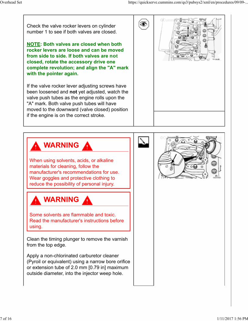
Check the valve rocker levers on cylindernumber 1 to see if both valves are closed.
NOTE: Both valves are closed when bothrocker levers are loose and can be movedfrom side to side. If both valves are notclosed, rotate the accessory drive onecomplete revolution; and align the "A" markwith the pointer again.
If the valve rocker lever adjusting screws havebeen loosened and not yet adjusted, watch thevalve push tubes as the engine rolls upon the"A" mark. Both valve push tubes will havemoved to the downward (valve closed) positionif the engine is on the correct stroke.
When using solvents, acids, or alkalinematerials for cleaning, follow themanufacturer's recommendations for use.Wear goggles and protective clothing toreduce the possibility of personal injury.
Some solvents are flammable and toxic.Read the manufacturer's instructions beforeusing.
Clean the timing plunger to remove the varnishfrom the top edge.
Apply a non-chlorinated carburetor cleaner(Pyroil or equivalent) using a narrow bore orificeor extension tube of 2.0 mm [0.79 in] maximumoutside diameter, into the injector weep hole.
Overhead Set https://quickserve.cummins.com/qs3/pubsys2/xml/en/procedures/09/09-...
7 of 16 1/11/2017 1:56 PM
If the entire overhead is to be reset, everyinjector is to be sprayed at this time.
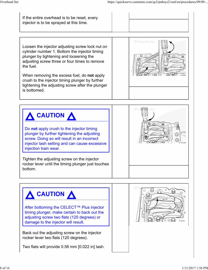
Loosen the injector adjusting screw lock nut oncylinder number 1. Bottom the injector timingplunger by tightening and loosening theadjusting screw three or four times to removethe fuel.
When removing the excess fuel, do not applycrush to the injector timing plunger by furthertightening the adjusting screw after the plungeris bottomed.
Do not apply crush to the injector timingplunger by further tightening the adjustingscrew. Doing so will result in an incorrectinjector lash setting and can cause excessiveinjection train wear.
Tighten the adjusting screw on the injectorrocker lever until the timing plunger just touchesbottom.
After bottoming the CELECT™ Plus injectortiming plunger, make certain to back out theadjusting screw two flats (120 degrees) ordamage to the injector will result.
Back out the adjusting screw on the injectorrocker lever two flats (120 degrees).
Two flats will provide 0.56 mm [0.022 in] lash.
Overhead Set https://quickserve.cummins.com/qs3/pubsys2/xml/en/procedures/09/09-...
8 of 16 1/11/2017 1:56 PM

The specification is 0.50 to 0.74 mm [0.020 to0.029 in] lash.
Hold the adjusting screw and tighten the locknut.
Torque Value: 65 n.m [50 ft-lb]
After setting the injector on a given cylinder, setthe valves on the same cylinder.
With the "A" set mark aligned with the pointeron the gear cover and both valves closed oncylinder number 1, loosen the lock nuts on theintake and the exhaust valve adjusting screws.
Select a feeler gauge for the correct valve lashspecification.
Valve Lash Specifications
Intake Exhaust
0.35 mm [0.014 in] 0.68 mm [0.027 in]
Insert the feeler gauge between the top of thecrosshead and the rocker lever pad.
Overhead Set https://quickserve.cummins.com/qs3/pubsys2/xml/en/procedures/09/09-...
9 of 16 1/11/2017 1:56 PM
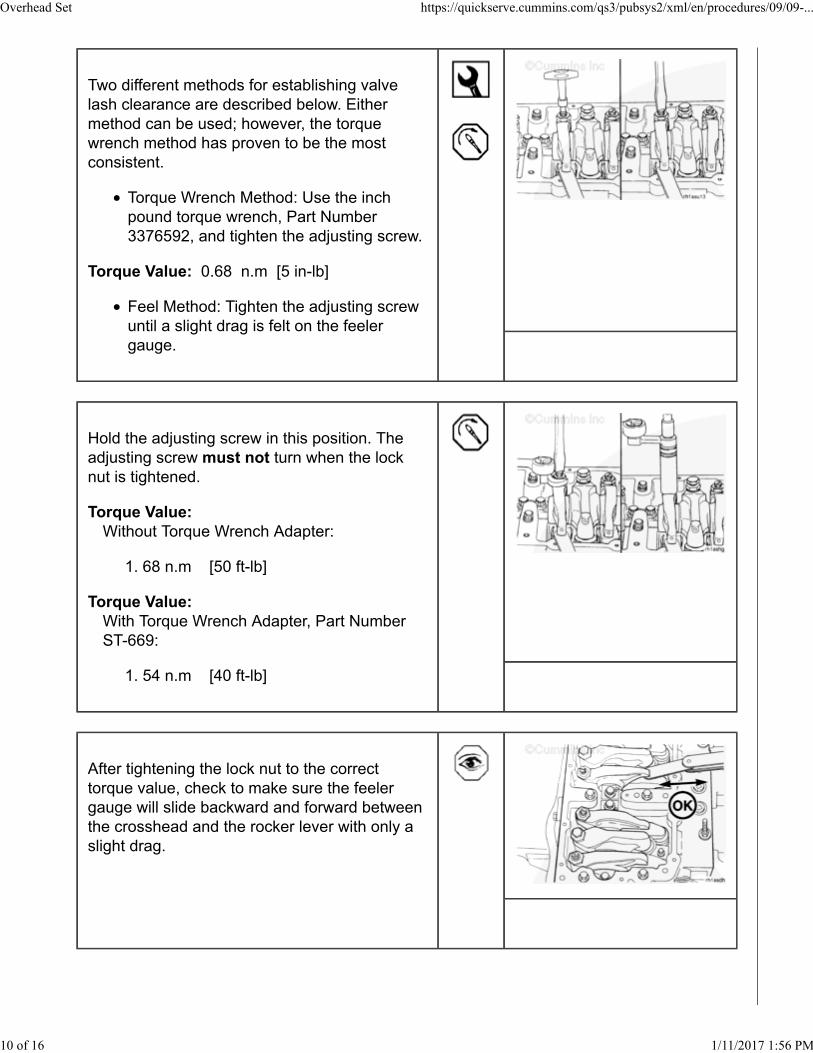
Two different methods for establishing valvelash clearance are described below. Eithermethod can be used; however, the torquewrench method has proven to be the mostconsistent.
Torque Wrench Method: Use the inchpound torque wrench, Part Number3376592, and tighten the adjusting screw.
Torque Value: 0.68 n.m [5 in-lb]
Feel Method: Tighten the adjusting screwuntil a slight drag is felt on the feelergauge.
Hold the adjusting screw in this position. Theadjusting screw must not turn when the locknut is tightened.
Torque Value:Without Torque Wrench Adapter:
68 n.m [50 ft-lb]1.
Torque Value:With Torque Wrench Adapter, Part NumberST-669:
54 n.m [40 ft-lb]1.
After tightening the lock nut to the correcttorque value, check to make sure the feelergauge will slide backward and forward betweenthe crosshead and the rocker lever with only aslight drag.
Overhead Set https://quickserve.cummins.com/qs3/pubsys2/xml/en/procedures/09/09-...
10 of 16 1/11/2017 1:56 PM

If using the feel method, attempt to insert afeeler gauge that is 0.03 mm [0.001 in] thickerbetween the crosshead and the rocker leverpad. The valve lash is not correct when athicker feeler gauge will fit.
After adjusting the injector on cylinder number 1and the valves on cylinder number 1, rotate theaccessory drive and align the next valve setmark with the pointer.
Adjust the appropriate injector and valvesfollowing the Injector and Valve AdjustmentSequence in the table below.
Repeat the process to adjust all injectors andvalves correctly.
CELECT™ Plus Engines
Injector and Valve Adjustment Sequence
Bar Engine inDirection ofRotation
PulleyPosition
Set Cylinder
Injector Valve
Start A 1 1
Advance to B 5 5
Advance to C 3 3
Advance to A 6 6
Advance to B 2 2
Overhead Set https://quickserve.cummins.com/qs3/pubsys2/xml/en/procedures/09/09-...
11 of 16 1/11/2017 1:56 PM

CELECT™ Plus Engines
Injector and Valve Adjustment Sequence
Bar Engine inDirection ofRotation
PulleyPosition
Set Cylinder
Injector Valve
Advance to C 4 4
Firing Order: 1-5-3-6-2-4
STC
Loosen the lock nut on the injector adjustingscrew on the cylinder number 5.
An overtightened setting on the injectoradjusting screw will produce increased stresson the injector train and the camshaft injectorlobes, which can result in engine damage.
Use a dial type torque wrench to tighten theinjector rocker lever adjusting screw to thespecified torque. If the screw causes chatteringduring setting, repair the screw and lever asrequired.
Hold the torque wrench in a position that allowsthe direct view of the dial. This is to make
Overhead Set https://quickserve.cummins.com/qs3/pubsys2/xml/en/procedures/09/09-...
12 of 16 1/11/2017 1:56 PM

certain that the reading on the dial is accurate.
Torque Value: 14 n.m [125 in-lb]
Hold the adjusting screw in this position. Theadjusting screw must not turn when the locknut is tightened. Tighten the lock nut.
Torque Value: 65 n.m [50 ft-lb]
With the “B” mark aligned with the pointer onthe gear cover and both valves closed oncylinder number 5, loosen the locknuts on theintake and the exhaust valve adjusting screws.
Select a feeler gauge for the correct valve lashspecification.
Valve Lash Specifications
mm inIntake 0.35 NOM [0.014]Exhaust 0.68 NOM [0.027]
Insert the feeler gauge between the top of thecrosshead and the rocker lever nose.
Overhead Set https://quickserve.cummins.com/qs3/pubsys2/xml/en/procedures/09/09-...
13 of 16 1/11/2017 1:56 PM

Two different methods for establishing valvelash clearance are described below. Eithermethod can be used: however, the torquewrench method has proven to be the mostconsistent.
Torque Wrench Method
Use the inch-pound torque wrench, PartNumber 3376592 or equivalent, (normallyused to set preload on STC injectors), andtighten the adjusting screw.
Torque Value: 0.56 to 0.68 n.m [5 to 6 in-lb]
Feel Method
Hold the adjusting screw in this position.The adjusting screw must not turn whenthe locknut is tightened. Tighten thelocknut.
Torque Value:With torque wrench adapter, Part Number3163196 or equivalent:
55 n.m [40 ft-lb]1.
Torque Value:Without torque wrench adapter:
65 n.m [50 ft-lb]1.
After tightening the locknut to the correct torquevalue, check to make sure the feeler gauge willslide backward and forward between thecrosshead and the rocker lever with only aslight drag.
Overhead Set https://quickserve.cummins.com/qs3/pubsys2/xml/en/procedures/09/09-...
14 of 16 1/11/2017 1:56 PM
If using the feel method, attempt to insert afeeler gauge that is 0.03 mm [0.001 in] thickerbetween the crosshead and the rocker leverpad. The valve lash is not correct when athicker feeler gauge will fit.
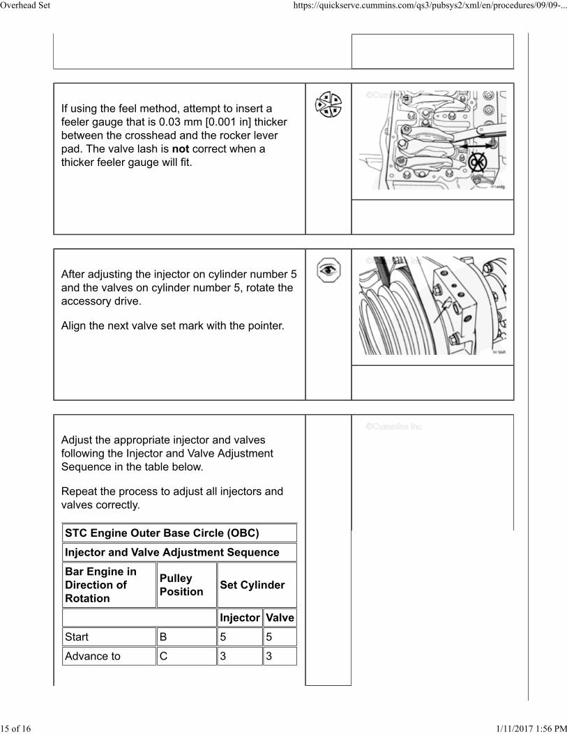
After adjusting the injector on cylinder number 5and the valves on cylinder number 5, rotate theaccessory drive.
Align the next valve set mark with the pointer.
Adjust the appropriate injector and valvesfollowing the Injector and Valve AdjustmentSequence in the table below.
Repeat the process to adjust all injectors andvalves correctly.
STC Engine Outer Base Circle (OBC)
Injector and Valve Adjustment Sequence
Bar Engine inDirection ofRotation
PulleyPosition
Set Cylinder
Injector Valve
Start B 5 5
Advance to C 3 3
Overhead Set https://quickserve.cummins.com/qs3/pubsys2/xml/en/procedures/09/09-...
15 of 16 1/11/2017 1:56 PM
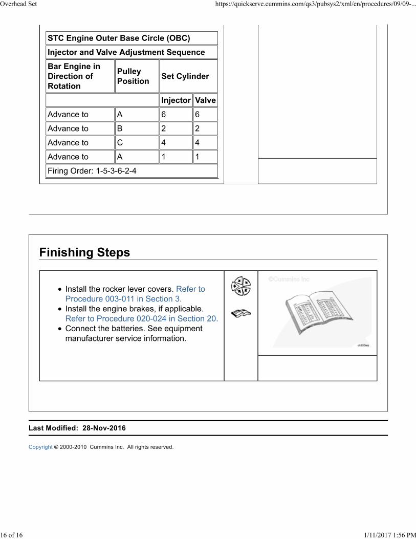
STC Engine Outer Base Circle (OBC)
Injector and Valve Adjustment Sequence
Bar Engine inDirection ofRotation
PulleyPosition
Set Cylinder
Injector Valve
Advance to A 6 6
Advance to B 2 2
Advance to C 4 4
Advance to A 1 1
Firing Order: 1-5-3-6-2-4
Install the rocker lever covers. Refer toProcedure 003-011 in Section 3.Install the engine brakes, if applicable.Refer to Procedure 020-024 in Section 20.Connect the batteries. See equipmentmanufacturer service information.
Last Modified: 28-Nov-2016
Copyright © 2000-2010 Cummins Inc. All rights reserved.
Overhead Set https://quickserve.cummins.com/qs3/pubsys2/xml/en/procedures/09/09-...
16 of 16 1/11/2017 1:56 PM