Preprint 13-050
7
SME Annual Meeting Feb. 24 - 27, 2013, Denver, CO 1 Copyright © 2013 by SME Preprint 13-050 UPDATES ON GEARED VS GEARLESS DRIVE SOLUTIONS FOR GRINDING MILLS R. Kalra, CITIC-HIC Pty Ltd, Sydney, NSW, Australia J. Jiangang, CITIC Heavy Industries Co., Ltd, Luoyang, Henan, China I. Druce, CITIC-HIC Pty Ltd, Sydney, NSW, Australia M. Rauscher, CITIC-HIC Pty Ltd, Sydney, NSW, Australia ABSTRACT The current paper looks at evaluating the merits of large geared mills versus gearless driven mills by evaluating the following factors: The capability of currently available systems in terms of power and mill diameter Efficiency in terms of overall electrical power consumed vs mechanical output power Capital cost Running costs Cooling requirements in terms of air versus water cooling Installation and delivery time World’s largest geared drive – 2x8500kW – Wushan, China (operating) Among the many reasons that geared drives on large SAG mills are not favoured, is due to not having an efficient variable speed drive option (60 to 80% critical speed), which is required for process reasons. As technological advances have occurred quite rapidly in recent years, this paper uses the latest data in applying these comparisons and attempts to dispel some of the myths regarding Slip Energy Recovery (SER) and variable frequency drive technology on twin pinion drive systems. Early attempts to provide load sharing on twin pinion drives used primitive electronics which have since been developed to eliminate the problems encountered in earlier attempts. In particular, torque pulsations between the twin motors have been overcome using a higher number of devices (pulses) and better electronics. With successful operation of 2 x 6.5MW (Phu Kham, Laos) and three 2 x 7MW units under manufacture (Pascu Lama) and a further 40 projects worldwide, energy efficient Hyper Synchronous SER drives are now mature and ready for use on 2 X 10MW dual drive mills. Speed variation required is in the range of +/- 15% of synchronous motor speeds. VVVF drive packages from ABB and Siemens are also available for 2 x 10MW in low and high speed options. Dual hydraulic inching drives provide a much safer and convenient operation with the added advantage of locked charge detection. INTRODUCTION Over the last several years, one of the biggest decisions that face the customers has been what type of drive system best suits their particular application. There has been a great deal of confusion particularly in terms of efficiency, durability, availability and value for money. This paper attempts to clear up this confusion using accurate information obtained from our own recent projects. HISTORY Girth gear drives have been, and continue to be, the primary method of driving SAG mills, Ball mills and other rotating elements. Several thousand grinding mills have been manufactured and have been in operation for the last century. The gearless drive came into the minerals industry in 1980 and as per their reference lists, Siemens have approximately 60 installations and ABB have approximately 85. The reasons why these gearless drives on mills came about in the late 1970’s is because of SAG mills requiring variable speed and the limitations of material of construction and the heavy manufacturing capabilities at the time. Girth gears have been going through enormous improvements over time following the use of FEA, casting software like MAGMA (using full ring risers with solidifications & cooling), ultrasonic testing and special materials of construction with improvement of hardness to 325BHN. Forged steel with ASTM standard materials and ultrasonic testing have improved the overall gear-set design capability. Some consultants have the view that the gear drive is limited in power. Mr Craig Denecki (Falk Milwaukee) in his paper, presented at the 1996 SAG mill conference, provided details of the then largest gear drive in operation on a SAG mill (34ft x 18ft) at Escondida 13.4MW, which began operation in 1995. The reason for not having larger gear drives was due to the limitation of gear manufacturers not having access to larger single piece special alloy castings. To the benefit of consumers CITIC HIC has now overcome this limitation and mine operators can now consider more cost effective larger gear driven mills. The World’s largest gear driven mill (manufactured at CITIC HIC) is now operating at Wushan Phase II (Ball Ø7.9m x 13.6m – 17MW- 2x8500kW) Figure 1. Gearless Mill Drive. DESIGN Materials of construction - gear & pinion Based on over 50 years of casting, heat treatment, machining, gear cutting and feedback from operating equipment, CITIC HIC have three different Chrome, Nickel and Molybdenum cast steel materials of construction. This cast material provides sufficient hardness in the root of the teeth and satisfies the strength requirements. Rolled forgings & plates are not preferred due to the grain structure aligned in the rolling direction. Castings provide an isotropic structure (not directional). The optimum design of the girth gear geometry considered by the design engineering team includes questions on material properties, module, pressure & helix angle, tooth width, flank contact pressure, pitch circle
Transcript of Preprint 13-050
SME Annual MeetingFeb. 24 - 27, 2013, Denver, CO
1 Copyright © 2013 by SME
Preprint 13-050
UPDATES ON GEARED VS GEARLESS DRIVE SOLUTIONS FOR GRINDING MILLS
R. Kalra, CITIC-HIC Pty Ltd, Sydney, NSW, AustraliaJ. Jiangang, CITIC Heavy Industries Co., Ltd, Luoyang, Henan, China
I. Druce, CITIC-HIC Pty Ltd, Sydney, NSW, AustraliaM. Rauscher, CITIC-HIC Pty Ltd, Sydney, NSW, Australia
ABSTRACT
The current paper looks at evaluating the merits of large gearedmills versus gearless driven mills by evaluating the following factors:
The capability of currently available systems in terms ofpower and mill diameter
Efficiency in terms of overall electrical power consumed vsmechanical output power
Capital cost Running costs Cooling requirements in terms of air versus water cooling Installation and delivery time World’s largest geared drive – 2x8500kW – Wushan, China
(operating)
Among the many reasons that geared drives on large SAG millsare not favoured, is due to not having an efficient variable speed driveoption (60 to 80% critical speed), which is required for processreasons. As technological advances have occurred quite rapidly inrecent years, this paper uses the latest data in applying thesecomparisons and attempts to dispel some of the myths regarding SlipEnergy Recovery (SER) and variable frequency drive technology ontwin pinion drive systems. Early attempts to provide load sharing ontwin pinion drives used primitive electronics which have since beendeveloped to eliminate the problems encountered in earlier attempts.In particular, torque pulsations between the twin motors have beenovercome using a higher number of devices (pulses) and betterelectronics. With successful operation of 2 x 6.5MW (Phu Kham, Laos)and three 2 x 7MW units under manufacture (Pascu Lama) and afurther 40 projects worldwide, energy efficient Hyper SynchronousSER drives are now mature and ready for use on 2 X 10MW dual drivemills. Speed variation required is in the range of +/- 15% ofsynchronous motor speeds. VVVF drive packages from ABB andSiemens are also available for 2 x 10MW in low and high speedoptions. Dual hydraulic inching drives provide a much safer andconvenient operation with the added advantage of locked chargedetection.
INTRODUCTION
Over the last several years, one of the biggest decisions that facethe customers has been what type of drive system best suits theirparticular application. There has been a great deal of confusionparticularly in terms of efficiency, durability, availability and value formoney. This paper attempts to clear up this confusion using accurateinformation obtained from our own recent projects.
HISTORY
Girth gear drives have been, and continue to be, the primarymethod of driving SAG mills, Ball mills and other rotating elements.Several thousand grinding mills have been manufactured and havebeen in operation for the last century. The gearless drive came into theminerals industry in 1980 and as per their reference lists, Siemenshave approximately 60 installations and ABB have approximately 85.The reasons why these gearless drives on mills came about in the late1970’s is because of SAG mills requiring variable speed and the
limitations of material of construction and the heavy manufacturingcapabilities at the time. Girth gears have been going through enormousimprovements over time following the use of FEA, casting software likeMAGMA (using full ring risers with solidifications & cooling), ultrasonictesting and special materials of construction with improvement ofhardness to 325BHN. Forged steel with ASTM standard materials andultrasonic testing have improved the overall gear-set design capability.Some consultants have the view that the gear drive is limited in power.Mr Craig Denecki (Falk Milwaukee) in his paper, presented at the 1996SAG mill conference, provided details of the then largest gear drive inoperation on a SAG mill (34ft x 18ft) at Escondida 13.4MW, whichbegan operation in 1995. The reason for not having larger gear driveswas due to the limitation of gear manufacturers not having access tolarger single piece special alloy castings. To the benefit ofconsumers CITIC HIC has now overcome this limitation and mineoperators can now consider more cost effective larger gear drivenmills. The World’s largest gear driven mill (manufactured at CITICHIC) is now operating at Wushan Phase II (Ball Ø7.9m x 13.6m –17MW- 2x8500kW)
Figure 1. Gearless Mill Drive.
DESIGN
Materials of construction - gear & pinionBased on over 50 years of casting, heat treatment, machining,
gear cutting and feedback from operating equipment, CITIC HIC havethree different Chrome, Nickel and Molybdenum cast steel materials ofconstruction. This cast material provides sufficient hardness in the rootof the teeth and satisfies the strength requirements. Rolled forgings &plates are not preferred due to the grain structure aligned in the rollingdirection. Castings provide an isotropic structure (not directional). Theoptimum design of the girth gear geometry considered by the designengineering team includes questions on material properties, module,pressure & helix angle, tooth width, flank contact pressure, pitch circle

SME Annual MeetingFeb. 24 - 27, 2013, Denver, CO
2 Copyright © 2013 by SME
of pinion and axial forces. For mill drives a 25° pressure angle ispreferred as it is approximately 10% stronger than a 20° pressureangle. Also the helix angle is limited to 7.5° to keep control on the axialforces. Spur gears with double meshing pinions drives are notpreferred for large mill drives as a single helical gear has more than50% rating than an equal sized spur gear. A single helical gear isquieter and will last longer than a comparable spur gear because of thehelical action.
Figure 2. Wushan Phase II.
Use of international standards for gear design – AGMA6114 –2006 (metric)
Single helical mill gear set calculations are carried out usingAGMA6114-2006 (metric) design standard. The AGMA6004 – F88standard was released in 1988 which applied to all large spur andhelical gears. For the same drive a calculation in accordance withAGMA6004 permitted increased power transmission by approximately10%. This standard has since been withdrawn and presently the newapplicable standard is AGMA6114 – 2006 (metric). This new AGMAstandard gives very slightly higher power transmission thanAGMA321.05. Adequate operating experience can only be expectedafter 10-15 years. AGMA321.05 1970 standard is still valid today forreference purposes. There are other conditions to consider namelyinstallation, operating, climate and selection of suitable lubricant.
FEA (finite element analysis)Design of the gear under load needs to be supported by a
suitable structure which is attached to the grinding mill body. Hencethe use of FEA is done in-house. This includes evaluation of pinion andtooth deflection under load. This FEA is done on nearly all CITIC HICmills.
Figure 3a. Gear FEA.
Figure 3b. Gear Tooth (Magnified 3a).
Inspection & testing – international standardsCITIC HIC manufacturers over a hundred gear sets every year
and all activities are done in house from casting, forging, heattreatment, carburizing, machining, gear cutting, shop assembly andtransport to ports of exports. This includes inspection and test plans forall major items which follow international ASTM & ISO standards with alarge team of NDT and inspection supervisors for all equipment andcomponents manufactured yearly.
MANUFACTURE
Ten gear cutters available at a single works include 2 x Ø5m, 3 xØ8m, 1 x Ø10m, 1 x Ø12m, 1 x Ø13m and 2 x Ø16m (one in climatecontrol). The gear hobber has the capacity to cut gears as large as16m (52 ft) in diameter and weighing up to 250 tons. The gear width forstraight teeth can be up to 1800mm (70 in). The machine is CNCcontrolled in 6 axis. The most significant advantage of a CNC gearhobbing machine against its traditional mechanical gear hobbingmodels is that the gear cutting production time can be shortenedsignificantly (about 5-10 times faster), because for CNC models, thecarbide tipped hobs with approximately 160 m/min surface speed canbe utilized verses only the 16 m/min HSS-cutters for the traditionalmechanical models. The CNC machines have additional advantagesover mechanical units, for example, the production of gears can beprogrammed and recorded within the CNC control system, which canbe used competitively; manufacturing gears of more complicatedshapes, such as spiral bevel gears; the structure of the machine issimplified and it is easier for operation and maintenance.
Figure 4. 16m CNC Gear Cutter.
SME Annual MeetingFeb. 24 - 27, 2013, Denver, CO
3 Copyright © 2013 by SME
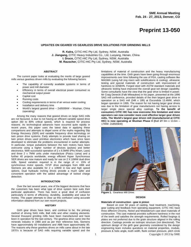
Figure 5. 16m CNC Gear Cutter (Six Axis).
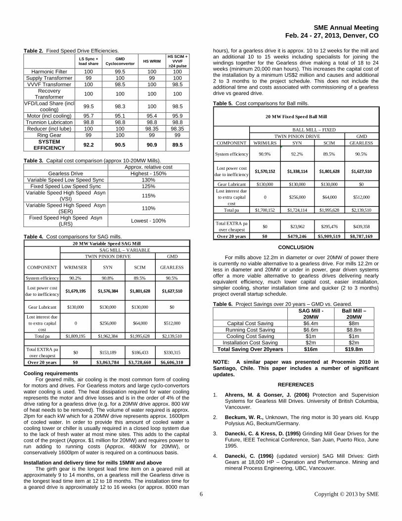
Gear Castings are first run on MAGMA software utilizing full ringrisers for solidification and cooling. Details are shown in figures 6 and7. Using this method requires that the actual metal pour of casting tobe approximately 2.5 times the net weight of the ring gear. Forexample, figure 8 illustrates a molten pour of 375t for a finished weightof a gear of 118t. The full ring gears are normally poured in a singlepiece even though they may be in quarters. This way it ensures thatthe complete gear has the same chemical analysis and it provides aneven hardness when heat treated. Molten pouring capacity is up to600t and hence we can do net gear casting weights of 250t.
Figure 6. Casting Techniques.
Presently the gearless drive is more costly than the completemechanical portion (mill rotating element and accessories supplied bythe mill manufacturers) and hence the customer/consultant needs tohave two parties to deal with from the start of any project. There is aninterface between the mill vendor and the gearless motor supplier.Figure 9 shows the mechanical interface data required to beexchanged with the client being the mediator for any issues. Afteraward to both parties (which must be done at the same time ) there isa time period of up to 6 weeks in getting certified data from Gearlessdrive supplier (Siemens or ABB) before the mill vendor can start theFEA & basic design work which takes a further 6/8 weeks. This is notthe case for mills with geared drive as engineering can commenceimmediately by the mill vendor.
Gearless drive rotating elements are heavier in construction thanan equivalent gear drive grinding mill. The cast heads are heavier with
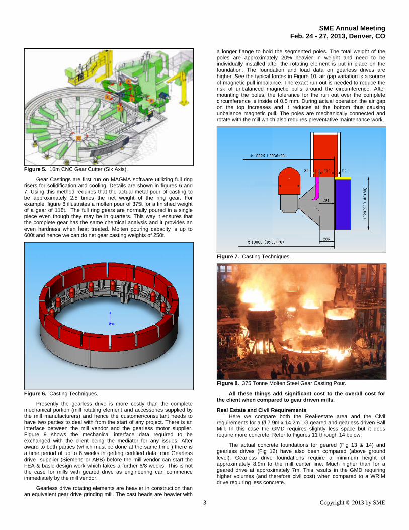
a longer flange to hold the segmented poles. The total weight of thepoles are approximately 20% heavier in weight and need to beindividually installed after the rotating element is put in place on thefoundation. The foundation and load data on gearless drives arehigher. See the typical forces in Figure 10, air gap variation is a sourceof magnetic pull imbalance. The exact run out is needed to reduce therisk of unbalanced magnetic pulls around the circumference. Aftermounting the poles, the tolerance for the run out over the completecircumference is inside of 0.5 mm. During actual operation the air gapon the top increases and it reduces at the bottom thus causingunbalance magnetic pull. The poles are mechanically connected androtate with the mill which also requires preventative maintenance work.
Figure 7. Casting Techniques.
Figure 8. 375 Tonne Molten Steel Gear Casting Pour.
All these things add significant cost to the overall cost forthe client when compared to gear driven mills.
Real Estate and Civil RequirementsHere we compare both the Real-estate area and the Civil
requirements for a Ø 7.9m x 14.2m LG geared and gearless driven BallMill. In this case the GMD requires slightly less space but it doesrequire more concrete. Refer to Figures 11 through 14 below.
The actual concrete foundations for geared (Fig 13 & 14) andgearless drives (Fig 12) have also been compared (above groundlevel). Gearless drive foundations require a minimum height ofapproximately 8.9m to the mill center line. Much higher than for ageared drive at approximately 7m. This results in the GMD requiringhigher volumes (and therefore civil cost) when compared to a WRIMdrive requiring less concrete.

SME Annual MeetingFeb. 24 - 27, 2013, Denver, CO
4 Copyright © 2013 by SME
Figure 9. Force transfer on Gearless Drives.
Figure 10. Gearless Mill Drive Foundation Analysis.
It is true the GMD drive does not require the real-estate for Motor,Pinion and Gearbox Lube systems however this area is easily off-setby the space needed for the GMD E-House.
In summary the Real-estate and Civil requirements of GearedDrive options compared to GMD’s are very similar overall and in mostcases would not form a deciding factor.
RESULTS AND DISCUSSION
Drive system capabilitiesThe largest mills manufactured to date are for the SINO Iron
Project in Western Australia. When fully completed there will be 6 off
28MW, Ø12.2m Variable Speed AG Mills and 6 off 15.6MW, Ø7.9mdual pinion fixed speed Ball mills.
Figure 11. Space Requirement Comparison.
Figure 12. GMD Civil Requirement.
Figure 13. WRIM Civil Requirement.
There is presently the capability to manufacture gearless drivesup to 35MW and present CITIC HIC manufacturing capabilitiesincludes the fabrication of mill shells up to Ø13.7m mill (45ft) with norestrictions on casting and machining for these units.

SME Annual MeetingFeb. 24 - 27, 2013, Denver, CO
5 Copyright © 2013 by SME
Figure 14. LSS Civil Requirement.
Figure 15. Mechanical Interface between Gearless Supplier and MillVendor.
GEAR DESIGN
SAG Mill Ball MillMill Diameter (m) 12.2 8.5
Motor Power (MW) 20 20Motors 2 x 10 MW 2 x 10 MW
Pinion Speeds (rpm) 160 150Mill Speed (rpm) 9.24 11.09
Pinion Gear Pinion GearNumber of teeth 21 344 21 288
Width of teeth (mm) 1080 1070 1080 1070Normal Modulus (mm) 42 42
Tool normal tooth profileangle (degrees)
25 25
Helical Angle (degrees) 7.5 7.5ISO 5 8 5 8Accuracy
Level Number AGMA 12 9 12 9Brinell
Hardness310 300Hardness of
tooth face(BHN) Rockwell
hardness57 57
Durability ≥ 1.75 ≥ 1.75AGMA 6114(min S.F) Strength ≥ 2.5 ≥ 2.75
Durability 2.75 1.81 3.20 1.94Actual SafetyFactor to
AGMA 6114 Strength 2.52 2.52 3.20 2.62
This gives the following mill drive capabilities:
GMD - Ball > 7.9m & SAG/AG > 11.5 m - >20MWDual Pinion - Ball <8.5m & SAG/AG <12.3m up to 20MWSingle Pinion - Ball < 7.4m / SAG/AG < 10.4m <10MW
Comparisons of efficiency in terms of electrical power consumedvs. mechanical output power
The efficiency of the drive system is made up of 2 majorcomponents, mechanical efficiency including the motor losses and theelectrical efficiency including the electrical drive and its supportingcomponents. If comparing only typical losses of the mechanicalcomponents alone it appears Gearless drive solutions outperform theGeared drive solutions however, this advantage changes when overallefficiency is taken into account.
All the below figures detailed in tables 1 through 4 are based onthe averages of documented figures provided by vendors in datasheetsor are derived from published papers (referenced in this paper). Thefollowing is a list of current projects using the various drive optionsreferred above.
Sino Iron – six 12.2m AG – 28MW GMD DrivesSino Iron – six 2x7.8MW Ball – Fixed HS Asynchronous with LRSKonkola Copper – 2.8MW + 5.5MW SAG – Variable HS
Asynchronous with SERKonkola Copper Mines – 3.5MW + 2x5.5MW Ball – Fixed HS
Asynchronous with LRSTISCO – four 2x5.5MW Ball + two 2x6.75MW Ball – Fixed LS
SynchronousJiangxi Copper – 2x5.5MW SAG + 2x5.5MW Ball – Fixed LS
SynchronousMMX (Serra Azul) four Ball Ø7.9m – 2x8250kW WRIMSamarco - Four Balll Ø6.1m – 2 x 4,200kW,Wushan Copper Gold - SAG Ø11m – 2 x 6,325kW, Ball Ø7.9m
LG – 2 x 8,500kW Low Speed Synchronous
Capital CostThe Fixed speed Asynchronous LRS option is the lowest cost
option, Table 4 uses this as a base price for comparison purposes. Thecapital costs are based on literally hundreds of mill estimatesundertaken over many years for project around the globe.
Table 1. Variable Speed Drive Efficiencies.LS Sync +
VVVF>24 pulse
GMDCycloinvertor
HS WRIM +SER
HS SCIM +VVVF
>24 pulse
Harmonic Filter 100 99.5 100 100Supply Transformer 100 100 99 100VVVF Transformer 98.5 98.5 100 98.5
RecoveryTransformer
100 100 99.8 100
VFD (incl cooling) 98.5 98.3 99.5 98.5Motor (incl cooling) 95.7 95.1 95.4 95.9Trunnion Lubricaton 98.8 98.8 98.8 98.8Reducer (incl lube) 100 100 98.35 98.35
Ring Gear 99 100 99 99SYSTEM
EFFICIENCY90.8 90.5 90.2 89.5
Running & Interest CostsThe main running cost by far is power. It can be easily calculated
on a cost per kW (10c per kWh used for comparison basis in belowtables) basis and the relative costs will be proportional to overallsystem efficiency as can be seen in the sample tables below. Girthgear and pinion lubricant have also been considered.
Initial capital cost saving are also significant. Not only in thecapital saving itself but also in terms of the lost interest costs of moreexpensive drive options. It must therefore be considered. Using table 4the lost interest costs for the more expensive drive options over thecheapest for either fixed or variable speed options has beenconsidered using an annual interest rate of 8%. Furthermore theinitial extra capital paid is not recouped and therefore lost, thiscapital loss must be added to the losses detailed below in table 5.
SME Annual MeetingFeb. 24 - 27, 2013, Denver, CO
6 Copyright © 2013 by SME
Table 2. Fixed Speed Drive Efficiencies.
LS Sync +load share
GMDCycloconvertor
HS WRIMHS SCIM +
VVVF>24 pulse
Harmonic Filter 100 99.5 100 100Supply Transformer 99 100 99 100VVVF Transformer 100 98.5 100 98.5
RecoveryTransformer
100 100 100 100
VFD/Load Share (inclcooling)
99.5 98.3 100 98.5
Motor (incl cooling) 95.7 95.1 95.4 95.9Trunnion Lubricaton 98.8 98.8 98.8 98.8Reducer (incl lube) 100 100 98.35 98.35
Ring Gear 99 100 99 99SYSTEM
EFFICIENCY 92.2 90.5 90.9 89.5
Table 3. Capital cost comparison (approx 10-20MW Mills).Approx. relative cost
Gearless Drive Highest - 150%Variable Speed Low Speed Sync 130%
Fixed Speed Low Speed Sync 125%Variable Speed High Speed Asyn
(VSI)115%
Variable Speed High Speed Asyn(SER)
110%
Fixed Speed High Speed Asyn(LRS)
Lowest - 100%
Table 4. Cost comparisons for SAG mills.
GMD
COMPONENT WRIM/SER SYN SCIM GEARLESS
System efficiency 90.2% 90.8% 89.5% 90.5%
Lost power cost
due to inefficiency$1,679,195 $1,576,384 $1,801,628 $1,627,510
Gear Lubricant $130,000 $130,000 $130,000 $0
Lost interest due
to extra capital
cost
0 $256,000 $64,000 $512,000
Total pa $1,809,195 $1,962,384 $1,995,628 $2,139,510
Total EXTRA pa
over cheapest$0 $153,189 $186,433 $330,315
Over 20 years $0 $3,063,784 $3,728,660 $6,606,310
20 MW Variable Speed SAG Mill
SAG MILL – VARIABLE
TWIN PINION DRIVE
Cooling requirementsFor geared mills, air cooling is the most common form of cooling
for motors and drives. For Gearless motors and large cyclo-convertorswater cooling is used. The heat dissipation required for water coolingrepresents the motor and drive losses and is in the order of 4% of thedrive rating for a gearless drive (e.g. for a 20MW drive approx. 800 kWof heat needs to be removed). The volume of water required is approx.2lpm for each kW which for a 20MW drive represents approx. 1600lpmof cooled water. In order to provide this amount of cooled water acooling tower or chiller is usually required in a closed loop system dueto the lack of fresh water at most mine sites. This adds to the capitalcost of the project (Approx. $1 million for 20MW) and requires power torun adding to running costs (Approx. 480kW for 20MW), orconservatively 1600lpm of water is required on a continuous basis.
Installation and delivery time for mills 15MW and aboveThe girth gear is the longest lead time item on a geared mill at
approximately 9 to 14 months, on a gearless mill the Gearless drive isthe longest lead time item at 12 to 18 months. The installation time fora geared drive is approximately 12 to 16 weeks (or approx. 8000 man
hours), for a gearless drive it is approx. 10 to 12 weeks for the mill andan additional 10 to 15 weeks including specialists for joining thewindings together for the Gearless drive making a total of 18 to 24weeks (minimum 20,000 man hours). This increases the capital cost ofthe installation by a minimum US$2 million and causes and additional2 to 3 months to the project schedule. This does not include theadditional time and costs associated with commissioning of a gearlessdrive vs geared drive.
Table 5. Cost comparisons for Ball mills.
GMD
COMPONENT WRIM/LRS SYN SCIM GEARLESS
System efficiency 90.9% 92.2% 89.5% 90.5%
Lost power cost
due to inefficiency$1,570,152 $1,338,114 $1,801,628 $1,627,510
Gear Lubricant $130,000 $130,000 $130,000 $0
Lost interest due
to extra capital
cost
0 $256,000 $64,000 $512,000
Total pa $1,700,152 $1,724,114 $1,995,628 $2,139,510
Total EXTRA pa
over cheapest$0 $23,962 $295,476 $439,358
Over 20 years $0 $479,246 $5,909,519 $8,787,169
20 MW Fixed Speed Ball Mill
BALL MILL – FIXED
TWIN PINION DRIVE
CONCLUSION
For mills above 12.2m in diameter or over 20MW of power thereis currently no viable alternative to a gearless drive. For mills 12.2m orless in diameter and 20MW or under in power, gear driven systemsoffer a more viable alternative to gearless drives delivering nearlyequivalent efficiency, much lower capital cost, easier installation,simpler cooling, shorter installation time and quicker (2 to 3 months)project overall startup schedule.
Table 6. Project Savings over 20 years – GMD vs. Geared.SAG Mill -
20MWBall Mill –
20MWCapital Cost Saving $6.4m $8m
Running Cost Saving $6.6m $8.8mCooling Cost Saving $1m $1m
Installation Cost Saving $2m $2mTotal Saving Over 20years $16m $19.8m
NOTE: A similar paper was presented at Procemin 2010 inSantiago, Chile. This paper includes a number of significantupdates.
REFERENCES
1. Ahrens, M. & Gonser, J. (2006) Protection and SupervisionSystems for Gearless Mill Drives. University of British Columbia,Vancouver.
2. Beckum, W. R., Unknown, The ring motor is 30 years old. KruppPolysius AG, Beckum/Germany.
3. Danecki, C. & Kress, D. (1995) Grinding Mill Gear Drives for theFuture, IEEE Technical Conference, San Juan, Puerto Rico, June1995.
4. Danecki, C. (1996) (updated version) SAG Mill Drives: GirthGears at 18,000 HP – Operation and Performance. Mining andmineral Process Engineering, UBC, Vancouver.

SME Annual MeetingFeb. 24 - 27, 2013, Denver, CO
7 Copyright © 2013 by SME
5. Dreher, M. (1998) The design of large gear tooth systems fordrives in the cement industry. ZKG International No. 6/98Cement-Lime-Gypsum, Vol 51. Joinville.
6. Frank, W. (1996) Gearless Drives Experiences and New/FutureDevelopments. Mineral and Process Engineering, UBC,Vancouver.
7. Kress, D. F. & Hanson, D. L. (1989) Design Concept ThroughOperating Criteria, University of British Columbia, Vancouver.
8. Roper, G., Manueco, C. & Bradley, P. (2006) Application of theHyper Ser Drive to Sag Mills. University of British Columbia,Vancouver.
9. Schachter, N. (1998) Experience with Synchronous and Slip RingInduction Motors Driving Cement Mills. CIMENTEC EngineeringLtd, IEEE Cement Industry.
10. Scheiss Brighton Website - http://www.schiessbrighton.com
11. Thomas, P. D. F. (1989) Development of S.A.G. Mill motorDrives. University of British Columbia, Vancouver.
12. Frank, W. (1989) Design and Application of Gearless Drives.Mineral and Process Engineering, UBC, Vancouver.
13. IES (July 2010), Reference List of Mill Drives supplied byInternational Electronics S.A. Spain Rev.