Preparing for HCFC phase-out: Fundamentals of uses - unido
244
UNITED NATIONS INDUSTRIAL DEVELOPMENT ORGANIZATION Preparing for HCFC phase-out: Fundamentals of uses, alternatives, implications and funding for Article 5 countries
Transcript of Preparing for HCFC phase-out: Fundamentals of uses - unido

UNITED NATIONS INDUSTRIAL DEVELOPMENT ORGANIZATION
Printed in AustriaV.09-83747—August 2009—750
UNITED NATIONS INDUSTRIAL DEVELOPMENT ORGANIZATIONVienna International Centre, P.O. Box 300, 1400 Vienna, AustriaTelephone: (+43-1) 26026-0, Fax: (+43-1) 26926-69E-mail: [email protected], Internet: www.unido.org
Preparing for HCFC phase-out:
Fundamentals of uses, alternatives, implications and funding for Article 5 countries
Preparing for HCFC phase-out: Fundam
entals of uses, alternatives, implications and funding for Article 5 countries


UNITED NATIONS INDUSTRIAL DEVELOPMENT ORGANIZATIONVienna, 2009
Preparing for HCFC phase-out:
Fundamentals of uses, alternatives, implications and funding for
Article 5 countries

The designations employed and the presentation of material in this publication do not imply the expression of any opinion whatsoever on the part of the Secretariat of the United Nations Industrial Development Organization concerning the legal status of any country, territory, city or area, or of its authorities, or concerning the delimitation of its frontiers or boundaries. The opinions, figures and estimates set forth are the respon-sibility of the authors and should not necessarily be considered as reflecting the views or carrying endorsement of UNIDO. The designations, “developed” and “developing” economies are intended for statistical convenience and do not necessarily express a judgment about the stage reached by a particular country or area in the development process. Mention of firm names or commercial products does not imply endorsement by UNIDO.

iii
Foreword
The concept of this guide was developed in response to feedback from representatives of over 30 Article 5 countries who attended a technical workshop on HCFC phase-out, hosted by UNIDO in Vienna in February 2008.
Feedback from the meeting and from general day-to-day communication with a number of UNIDO’s partners indicates that a better understanding of the technical and policy issues relating to HCFC phase-out is needed at the local level to facilitate implementa-tion of phase-out in Article 5 countries.
A wide variety of stakeholders with very different levels of technical knowledge, imple-mentation experience and exposure to the operational mechanisms of the Multilateral Fund will have to be engaged to achieve the phase-out of HCFCs. And although consid-erable experience has already been gained through CFC phase-out activities, the nature and variety of HCFC applications, particularly in the refrigeration and air-conditioning sector, are more complex.
Of course, a very large volume of information, data and commentary is available through a number of official and unofficial sources. However, the volume and range of informa-tion available can be overwhelming to people who are unfamiliar with the subject or who lack technical training. Even people with specific experience in one area of phase-out often lack understanding in other areas.
Most of the information used in this publication is currently available in the public domain, and a list of reference sources is included. Some material has been created spe-cifically for this publication, where it was felt that a clearer explanation could be given.
The principal aim of this guide is to bring together in a single publication a broad range of information and guidance in sufficient detail to make it a useful reference tool for a relatively wide audience. This might include national consultants in Article 5 countries, ozone office staff, industry stakeholders, government representatives and other stake-holders in HCFC phase-out.
Due to the highly technical nature of many of the issues, the guide cannot cover subjects in the level of detail available in specific publications, and it is not therefore intended to be a definitive document. However, it does aim to provide at least a basic understanding of the main technical, policy and tactical issues of HCFC phase-out under the Montreal Protocol.
Neither is the guide designed to be read from cover to cover, although someone new to this issue might find it a reasonable introduction, but rather to be used section by section. Someone familiar with the overall operation of the Multilateral Fund and the Montreal Protocol might want to understand a little more about the applications of HCFCs in refrigeration and air conditioning in order to understand a particular project proposal. On the other hand, a technical specialist familiar with refrigeration and air-conditioning theory might want to understand the basic operating model of the Multi-lateral Fund and what sort of information will be needed by the national ozone unit to compile a phase-out strategy.

iv
With this aim in mind, the publication brings together in a single document a range of background, technical and policy information on the most relevant issues relating to HCFC phase-out in Article 5 countries.
The guide does not replace any of the valuable reference sources from which it draws, but it does bring together some of the most important information in an accessible publication that can be easily distributed. This is not a textbook, but it might be a useful starting point from which users can go on to explore more detailed texts.
Clearly, this guide does not do away with the need for proper evaluation and consulta-tion in relation to HCFC phase-out, but it aims to provide the basic information and concepts required to give non-specialists a general understanding of the subject. It will enable them to follow the technical and policy issues and will assist them in their day-to-day work. It will also enhance their ability to ask the right questions and to seek appropriate further guidance.
This publication contains information available up to November 2008; the need to update it will be reviewed on an ongoing basis.
Refrigerant and foaming-agent names used in this publication
There are very many refrigerants and foaming agents in use at the present time. Some of these are single or pure substances, but many are blends of two or more substances. For consistency in compiling this document, pure substances are referred to in the text using their chemical group name, for example HCFC-22, HFC-134a or HCFC-141b.
Refrigerant blends are referred to by their so-called “R-numbers”, which are interna-tionally recognized classifications for particular mixtures of substances. For example, R-410A, which is a mixture of 50 per cent HFC-32 and 50 per cent HFC-125. The R-numbering system is described in chapter 8. In the data tables in chapter 8, R numbers are used throughout to avoid confusion.

v
AcknowledgementsThis document was drafted by Tamas Grof of UNIDO and Cameron Murdoch of Murdoch-Consulting.
Special thanks go to Lambert Kuijpers, Co-Chair of the Montreal Protocol Technology and Economic Assessment Panel, and the following international consultants: Richard Abrowkwa, Paul Ashford, Ryuchi Oshima and Valerie Smirnoff. Without their technical reviews and advice, this document would not have been possible. Thanks also to Jean Datta for her persistence in editing the document.
In the preparation of this document, the team made full use of the inputs generated dur-ing the Technical Workshop on HCFC phase-out, hosted by UNIDO in February 2008 and the Technical Meeting on HCFC phase-out, 5-6 April 2008, Montreal, Canada, sponsored by the European Commission and hosted by ICF International.
The publication also benefited from relevant information accumulated in the course of preparation and implementation of UNIDO’s ongoing projects funded by the Multilateral Fund for the Implementation of the Montreal Protocol.


vii
Contents
Foreword . . . . . . . . . . . . . . . . . . . . . . . . . . . . . . . . . . . . . . . . . . . . . . . . . . . . . . . . . . .iii
Acknowledgements . . . . . . . . . . . . . . . . . . . . . . . . . . . . . . . . . . . . . . . . . . . . . . . . . . . v
1. Introduction . . . . . . . . . . . . . . . . . . . . . . . . . . . . . . . . . . . . . . . . . . . . . . . . . . . . . 1
1 .1 Damage to the ozone layer . . . . . . . . . . . . . . . . . . . . . . . . . . . . . . . . . . . . . . 1
1 .2 Ozone-depleting potential . . . . . . . . . . . . . . . . . . . . . . . . . . . . . . . . . . . . . . . 2
1 .3 Direct environmental impact . . . . . . . . . . . . . . . . . . . . . . . . . . . . . . . . . . . . . 3
1 .4 Indirect environmental impact . . . . . . . . . . . . . . . . . . . . . . . . . . . . . . . . . . . . 4
2. The Montreal Protocol . . . . . . . . . . . . . . . . . . . . . . . . . . . . . . . . . . . . . . . . . . . . 7
2 .1 Background . . . . . . . . . . . . . . . . . . . . . . . . . . . . . . . . . . . . . . . . . . . . . . . . . 7
2 .2 Assistance for developing countries . . . . . . . . . . . . . . . . . . . . . . . . . . . . . . . 11
2 .3 Implementation of the Montreal Protocol . . . . . . . . . . . . . . . . . . . . . . . . . . . 12
3. Climate change . . . . . . . . . . . . . . . . . . . . . . . . . . . . . . . . . . . . . . . . . . . . . . . . . 17
3 .1 The UNFCCC and the Kyoto Protocol . . . . . . . . . . . . . . . . . . . . . . . . . . . . . . 17
3 .2 Greenhouse gases . . . . . . . . . . . . . . . . . . . . . . . . . . . . . . . . . . . . . . . . . . . . 19
3 .3 Environmental impact of greenhouse gases . . . . . . . . . . . . . . . . . . . . . . . . . 22
3 .4 Overall life-cycle environmental impact . . . . . . . . . . . . . . . . . . . . . . . . . . . . 23
3 .5 Relationship between HCFC phase-out and climate change . . . . . . . . . . . . 27
4. Accelerated phase-out of HCFCs . . . . . . . . . . . . . . . . . . . . . . . . . . . . . . . . . . . . 31
4 .1 Introduction . . . . . . . . . . . . . . . . . . . . . . . . . . . . . . . . . . . . . . . . . . . . . . . . . 31
4 .2 Decision XIX/6 of the Parties to the Montreal Protocol . . . . . . . . . . . . . . . . . 31
4 .3 Decisions of the Executive Committee of the Multilateral Fund . . . . . . . . . . . 32
5. Developing an HCFC phase-out Strategy . . . . . . . . . . . . . . . . . . . . . . . . . . . . . 41
5 .1 Introduction . . . . . . . . . . . . . . . . . . . . . . . . . . . . . . . . . . . . . . . . . . . . . . . . 41
5 .2 Technical feasibility . . . . . . . . . . . . . . . . . . . . . . . . . . . . . . . . . . . . . . . . . . . 41
5 .3 Availability . . . . . . . . . . . . . . . . . . . . . . . . . . . . . . . . . . . . . . . . . . . . . . . . . . 41
5 .4 Local technical capacity and industry practice . . . . . . . . . . . . . . . . . . . . . . . 42
5 .5 Economic viability . . . . . . . . . . . . . . . . . . . . . . . . . . . . . . . . . . . . . . . . . . . . 43
5 .6 Environmental impact . . . . . . . . . . . . . . . . . . . . . . . . . . . . . . . . . . . . . . . . . 44
6. Preparing an HCFC phase-out management plan . . . . . . . . . . . . . . . . . . . . . . 47
6 .1 Introduction . . . . . . . . . . . . . . . . . . . . . . . . . . . . . . . . . . . . . . . . . . . . . . . . . 47
6 .2 Guidelines for HCFC phase-out management plans (HPMPs) . . . . . . . . . . . . 47
6 .3 Funding . . . . . . . . . . . . . . . . . . . . . . . . . . . . . . . . . . . . . . . . . . . . . . . . . . . 51
6 .4 Investment projects . . . . . . . . . . . . . . . . . . . . . . . . . . . . . . . . . . . . . . . . . . . 52
6 .5 Demonstration projects . . . . . . . . . . . . . . . . . . . . . . . . . . . . . . . . . . . . . . . . 53
7. Fundamentals of refrigeration and air conditioning . . . . . . . . . . . . . . . . . . . 55
7 .1 Introduction . . . . . . . . . . . . . . . . . . . . . . . . . . . . . . . . . . . . . . . . . . . . . . . . . 55
7 .2 How do refrigeration and air-conditioning systems work? . . . . . . . . . . . . . . 55
7 .3 Lubricants for refrigeration systems . . . . . . . . . . . . . . . . . . . . . . . . . . . . . . . 61
7 .4 Common types of compressors . . . . . . . . . . . . . . . . . . . . . . . . . . . . . . . . . . 62

viii
7 .5 Refrigerants . . . . . . . . . . . . . . . . . . . . . . . . . . . . . . . . . . . . . . . . . . . . . . . 64
7 .6 Energy consumption . . . . . . . . . . . . . . . . . . . . . . . . . . . . . . . . . . . . . . . . 65
7 .7 Aspects of refrigeration and air-conditioning design . . . . . . . . . . . . . . . . 66
7 .8 Types of air-conditioning systems . . . . . . . . . . . . . . . . . . . . . . . . . . . . . . . 69
7 .9 Heat pumps . . . . . . . . . . . . . . . . . . . . . . . . . . . . . . . . . . . . . . . . . . . . . . . 74
7 .10 Types of refrigeration systems . . . . . . . . . . . . . . . . . . . . . . . . . . . . . . . . . 74
18. Refrigerants . . . . . . . . . . . . . . . . . . . . . . . . . . . . . . . . . . . . . . . . . . . . . . . . . . . 85
8 .1 Brief history . . . . . . . . . . . . . . . . . . . . . . . . . . . . . . . . . . . . . . . . . . . . . . . 85
8 .2 Naming of refrigerants . . . . . . . . . . . . . . . . . . . . . . . . . . . . . . . . . . . . . . 86
8 .3 Development of alternative refrigerants . . . . . . . . . . . . . . . . . . . . . . . . . . 88
8 .4 Safety group classifications . . . . . . . . . . . . . . . . . . . . . . . . . . . . . . . . . . . 90
8 .5 . Types and status of refrigerants . . . . . . . . . . . . . . . . . . . . . . . . . . . . . . . . 92
8 .6 Refrigerants, lubricants and system considerations . . . . . . . . . . . . . . . . . . 94
8 .7 Natural refrigerants . . . . . . . . . . . . . . . . . . . . . . . . . . . . . . . . . . . . . . . . . 99
8 .8 Refrigerant data . . . . . . . . . . . . . . . . . . . . . . . . . . . . . . . . . . . . . . . . . . 103
19. Alternatives for refrigeration and air conditioning . . . . . . . . . . . . . . . . . . 109
9 .1 Introduction . . . . . . . . . . . . . . . . . . . . . . . . . . . . . . . . . . . . . . . . . . . . . 109
9 .2 Overview of HCFC consumption . . . . . . . . . . . . . . . . . . . . . . . . . . . . . . 109
9 .3 General considerations . . . . . . . . . . . . . . . . . . . . . . . . . . . . . . . . . . . . . 110
9 .4 Refrigerant options for new air-conditioning equipment . . . . . . . . . . . . 110
9 .5 Refrigerant options for existing air-conditioning equipment . . . . . . . . . 118
9 .6 Refrigerant options for new commercial refrigeration equipment . . . . . . 121
9 .7 Refrigerant options for existing commercial refrigeration equipment . . . 123
9 .8 Refrigerant options for new industrial refrigeration systems . . . . . . . . . . 125
9 .9 Options for existing industrial systems . . . . . . . . . . . . . . . . . . . . . . . . . . 128
9 .10 Transport refrigeration . . . . . . . . . . . . . . . . . . . . . . . . . . . . . . . . . . . . . 129
10. Good service practice . . . . . . . . . . . . . . . . . . . . . . . . . . . . . . . . . . . . . . . . . . 133
10 .1 Introduction . . . . . . . . . . . . . . . . . . . . . . . . . . . . . . . . . . . . . . . . . . . . . 133
10 .2 Assessing options for existing equipment . . . . . . . . . . . . . . . . . . . . . . . . 133
10 .3 Identification of equipment . . . . . . . . . . . . . . . . . . . . . . . . . . . . . . . . . . 134
10 .4 Refrigerant audit . . . . . . . . . . . . . . . . . . . . . . . . . . . . . . . . . . . . . . . . . . 134
10 .5 Review options . . . . . . . . . . . . . . . . . . . . . . . . . . . . . . . . . . . . . . . . . . . 135
10 .6 Reducing leakage . . . . . . . . . . . . . . . . . . . . . . . . . . . . . . . . . . . . . . . . . 135
10 .7 Retrofilling with a “drop-in” . . . . . . . . . . . . . . . . . . . . . . . . . . . . . . . . . 137
10 .8 Retrofitting with an HFC refrigerant . . . . . . . . . . . . . . . . . . . . . . . . . . . . 138
10 .9 Reducing climatic impact . . . . . . . . . . . . . . . . . . . . . . . . . . . . . . . . . . . . 139
11. Foam fundamentals. . . . . . . . . . . . . . . . . . . . . . . . . . . . . . . . . . . . . . . . . . . . 143
11 .1 Introduction . . . . . . . . . . . . . . . . . . . . . . . . . . . . . . . . . . . . . . . . . . . . . 143
11 .2 Polyurethane . . . . . . . . . . . . . . . . . . . . . . . . . . . . . . . . . . . . . . . . . . . . . 143
11 .3 How polyurethane is made . . . . . . . . . . . . . . . . . . . . . . . . . . . . . . . . . . 144
11 .4 Polyurethane foam . . . . . . . . . . . . . . . . . . . . . . . . . . . . . . . . . . . . . . . . 146
11 .5 Rigid polyurethane foam . . . . . . . . . . . . . . . . . . . . . . . . . . . . . . . . . . . 151

ix
11 .6 Polystyrene . . . . . . . . . . . . . . . . . . . . . . . . . . . . . . . . . . . . . . . . . . . . . . 157
11 .7 Extruded expanded polystyrene foam (XPS) . . . . . . . . . . . . . . . . . . . . . . 159
11 .8 Polyolefin foams . . . . . . . . . . . . . . . . . . . . . . . . . . . . . . . . . . . . . . . . . . 162
12. Alternative blowing agents for foam production . . . . . . . . . . . . . . . . . . . 165
12 .1 Introduction . . . . . . . . . . . . . . . . . . . . . . . . . . . . . . . . . . . . . . . . . . . . . 165
12 .2 Rigid polyurethane foam . . . . . . . . . . . . . . . . . . . . . . . . . . . . . . . . . . . . 165
12 .3 Integral-skin foams . . . . . . . . . . . . . . . . . . . . . . . . . . . . . . . . . . . . . . . . 172
12 .4 Extruded polystyrene . . . . . . . . . . . . . . . . . . . . . . . . . . . . . . . . . . . . . . 172
12 .5 Polyolefin foam . . . . . . . . . . . . . . . . . . . . . . . . . . . . . . . . . . . . . . . . . . 175
12 .6 Methyl formate . . . . . . . . . . . . . . . . . . . . . . . . . . . . . . . . . . . . . . . . . . 176
12 .7 Summary of blowing-agent technology . . . . . . . . . . . . . . . . . . . . . . . . . 177
13. Cost implications of HCFC phase-out . . . . . . . . . . . . . . . . . . . . . . . . . . . . . . 183
13 .1 Background . . . . . . . . . . . . . . . . . . . . . . . . . . . . . . . . . . . . . . . . . . . . . . 183
13 .2 Effect of high costs of HCFC alternatives . . . . . . . . . . . . . . . . . . . . . . . . 184
13 .3 Foam sector costs . . . . . . . . . . . . . . . . . . . . . . . . . . . . . . . . . . . . . . . . . 184
13 .4 Refrigeration sector costs . . . . . . . . . . . . . . . . . . . . . . . . . . . . . . . . . . . 191
14. Phase-out experience from non-Article 5 countries . . . . . . . . . . . . . . . . . . 197
14 .1 HCFC phase-out . . . . . . . . . . . . . . . . . . . . . . . . . . . . . . . . . . . . . . . . . . 197
14 .2 Regulation of HFCs . . . . . . . . . . . . . . . . . . . . . . . . . . . . . . . . . . . . . . . . 198
Appendix A . . . . . . . . . . . . . . . . . . . . . . . . . . . . . . . . . . . . . . . . . . . . . . . . . . . . . . . 199

x
ABBREVIATIONS
CDM Clean Development MechanismCFC ChlorofluorocarbonDX Direct expansionEPS Expanded polystyreneExCom Executive Committee of the Multilateral FundF-gas Fluorinated gasGWP Global warming potentialGHG Greenhouse gasHC HydrocarbonHCFC HydrochlorofluorocarbonHDI Hexamethylene diisocyanateHFC HydrofluorocarbonHPMP HCFC phase-out management planILCIC Indicative list of categories of incremental costsICC Incremental capital costsIOC Incremental operating costsIOS Incremental operating savingsIPDI Isophorone diisocyanateLCCP Life-cycle climate performanceLFL Lower flammability limitLP Liquefied petroleumLPG Liquefied petroleum gasMAC Mobile air conditioningMDI Methyl di-p-phyenylene isocyanateMLF Multilateral FundNOU National ozone unitODP Ozone-depleting potentialODS Ozone-depleting substancePAG Poly alkylene glycolPAO PolyalphaolefinPOE Polyol esterPU PolyurethanePVE PolyvinyletherRMP Refrigerant management planSMEs Small and medium-sized enterprisesTDI Toluene diisocyanateTEWI Total equivalent warming impactTLV-TWA Threshold value—time-weighted averageTPMP Terminal phase-out management planUNFCCC United Nations Framework Convention on Climate ChangeVOC Volatile organic compound VRF Variable refrigerant flowXPS Extruded polystyrene

1
1. Introduction
The issues of ozone depletion and climate change have been at the forefront of the international community’s environmental agenda for several years. It is now generally accepted that man-made chemicals and human activities are having a significant adverse impact on the global climate.
The focus of this guide is to assist Article 5 countries with the phase-out of HCFCs. This is a complex issue with interlinking environmental, economic, technical and social aspects. It is therefore impossible to consider the topic of HCFC phase-out in isolation; an overarching approach is required.
There are several environmental considerations which either influence the selection of an HCFC phase-out strategy or are influenced by the choice of HCFC alternatives. This guide addresses the key policy, environmental and technical issues surrounding HCFC phase-out and the sources of funding available to assist Article 5 countries.
This section provides some background information on the environmental impacts of ozone-depleting substances and the main terms used to describe and define them. The relationship between HCFC phase-out and global warming is discussed further in chapter 4.
1.1 Damage to the ozone layer
Ozone is a naturally occurring but rare gas; its molecules are made up of three atoms of oxygen. Ozone forms in the stratosphere between 10 and 50 kilometres above the earth as incoming ultraviolet radiation breaks molecular oxygen (two atoms) into atomic oxy-gen (a single atom). When a free oxygen atom encounters an oxygen molecule, they may bond to form a molecule of ozone (O3). Ninety per cent of ozone exists in the strato-sphere, the upper atmosphere. Although it is rare, ozone is essential to life on earth. The ozone layer absorbs most of the harmful ultraviolet-B radiation from the sun and filters out lethal UV-C radiation.
The total amount of ozone above the surface of the earth varies with location on time-scales that range from daily to seasonal. The variations are caused by stratospheric winds and the chemical production and destruction of ozone. Total ozone is generally lowest at the equator and highest near the poles because of the seasonal wind patterns in the stratosphere.
It should also be noted that ozone is a “secondary pollutant” resulting from the chemi-cal reaction of primary pollutants (volatile organic compounds) in the presence of sunlight.
In 1985, scientists discovered a hole in the stratospheric ozone layer above the Antarctic. This discovery raised concerns amongst the international scientific community.
High stratospheric clouds are made up of tiny particles of frozen water, which contain chlorine held in inactive compounds such as hydrogen chloride, hydrochloric acid and

Preparing for HCFC phase-out: Fundamentals of uses, alternatives, implications and funding for Article 5 countries2
chlorine nitrate (at temperatures lower than around –85° C.). These compounds do not react with ozone during the darker winter months, but when spring arrives, ultra-violet radiation from the sun acts as a catalyst and causes reactions on the surfaces of the water particles, converting the inactive compounds to reactive chlorine monoxide, which destroys ozone at a very rapid rate. Similar reactions occur with bromine, which destroys ozone at an even greater rate.
The human-produced chemicals which have provided most of the chlorine and bromine for ozone depletion are methyl bromide, methyl chloroform, carbon tetrachloride and families of chemicals known as halons, chlorofluorocarbons (CFCs) and hydrochlo-rofluorocarbons (HCFCs).
The ozone layer over the Antarctic has steadily weakened since measurements started in the 1980s, and in 2003, the size of the ozone hole peaked at around 28 million square kilometres, making it the second largest on record.
Stratospheric ozone depletion is a different issue from that of formation in the lower troposphere of ozone, which is considered an air pollutant. Polluting ozone is a product of the interaction of nitrogen oxides and organic pollutants with the sunlight. The mixture of these chemicals in the atmosphere at the earth’s surface is known as urban “smog”.
Stratospheric ozone depletion is directly related to the issue of climate change. Ozone and some ozone-depleting substances, especially CFCs, are greenhouse gases. Ozone depletion produces an indirect cooling effect, while an abundance of ozone-depleting substances (ODS) results in the warming of the atmosphere. These two climate-forcing mechanisms do not simply offset one another. The interaction between these two proc-esses is more complicated. However, it is well established that the phase-out of CFCs, which have a high global warming potential, has resulted in a significant reduction of CO
2-equivalent emissions.
1.2 Ozone-depleting potential
The amount of damage done to the ozone layer is different for different chemicals. The destructive capacity of a chemical depends (amongst other factors) on the number of chlorine or bromine atoms in a molecule and how long the chemical persists in the atmosphere before being broken down itself. The ozone-depleting potential (ODP) of a chemical is a simple measure of its relative ability to destroy stratospheric ozone. It depends on the percentage of chlorine or bromine atoms in the molecule and the life-time of the compound in the atmosphere.
The ozone-depleting potential is a relative measure and describes how harmful a sub-stance is relative to one of the most commonly used ozone-depleting substances at the time when the Montreal Protocol came into being. This benchmark chemical is chloro-fluorocarbon, CFC-11, which is assigned an ozone-depleting potential (ODP) of 1.0. The ozone-depleting potentials of all other chemicals are assessed in terms of the extent to which they are more or less ozone destructive compared to the same unit mass of CFC-11.

3chapter 1 Introduction
Therefore, a chemical with an ozone-depleting potential of 2.0 is twice as harmful as CFC-11 and a chemical with an ODP of 0.2 is approximately one-fifth as harmful as CFC-11.
1.3 Direct environmental impact
A number of commonly used chemicals have been found to be extremely damaging to the ozone layer (see table 1). Halocarbons are chemicals in which one or more carbon atoms are linked by covalent bonds with one or more halogen atoms (fluorine, chlorine, bromine or iodine). Halocarbons containing bromine usually have much higher ODPs than those containing chlorine because, atom for atom, bromine (Br) is a more effective ozone-destruction catalyst than chlorine (Cl).
Table 1. Examples of ozone depleting potentials
Chemical Common name ODP
Chlorodifluoromethane HCFC-22 0.05
1,1,1 trichloroethane methyl chloroform 0.12
Monochloropentafluoroethane CFC-115 0.60
Trichlorofluoromethane CFC-11 1.00
Carbon tetrachloride carbon tetrachloride 1.10
Bromochlorodifluoromethane Halon 1211 3.00
Bromotrifluoromethane Halon 1301 10.00
Source: Ozone Secretariat Handbook 2006
Many CFCs, HCFCs and HFCs being released into the atmosphere manifest them-selves as effective greenhouse gases because they absorb infrared radiation going out from the earth’s surface. Halocarbons can be much more efficient in absorbing radiant energy than CO
2. Global warming potential (GWP) is used to measure the warming
impact of specific chemicals (see table 2). The GWP is an index comparing the climatic impact of a greenhouse gas with the impact of the same quantity of CO
2 emitted into
the atmosphere over a fixed time horizon. The GWPs of some common halocarbons are shown in the following table.
As an example, 1 kg of refrigerant emissions (R410A) has the same greenhouse impact as about two tons of carbon dioxide, which is the equivalent of running an average vehicle for 10,000 km.
Table 2. Examples of global warming potentials
ChemicalGWP
(100-yr)
CFC-11 4,750*
CFC-12 10,900*
Carbon tetrachloride 1,400*

Preparing for HCFC phase-out: Fundamentals of uses, alternatives, implications and funding for Article 5 countries4
ChemicalGWP
(100-yr)
Halon-1211 1,890*
Halon-1301 7,140*
HCFC-22 1,810*
HFC-23 14,800*
HCFC-141b 725*
HFC-134a 1,430*
R-410A 2,100
R-407C 1,800
* Intergovernmental Panel on Climate Change, fourth assessment report, Working Group 1
1.4 Indirect environmental impact
The environmental impact discussed so far is related to the direct impact on ozone depletion and/or global warming of chemicals released into the atmosphere either naturally or as a result of human activities. For example, methane is released by animals, causing climate impact (natural), and refrigerants can be released during the servicing of equipment (human activity).
In refrigeration and air-conditioning systems, refrigerants can leak during normal operation if the system is not adequately sealed or during maintenance when systems are dismantled or when the system is disposed of at the end of its lifetime.
Similarly, in the production of open-cell foams such as those used for cushioning furni-ture, the blowing agent is released into the atmosphere after the foam has been formed. Once it has been released, the impact caused on the environment is based on the mass of chemical released and its ozone-depletion and global-warming potentials.
However, any system or process that requires an input of energy derived from fossil fuels has an indirect impact on greenhouse gas emissions. This is because burning fuel to generate heat or electricity results in CO
2 emissions, and CO
2 is a major greenhouse
gas.
The indirect impact is particularly important in relation to refrigeration and air- conditioning systems, since these consume significant amounts of electrical power during their lifetimes, which may be more than 20 years. For insulating foams, the contribution to energy-saving is an even more important factor, in view of the potential for even longer lifetimes.
The total environmental impact attributed to refrigeration or air-conditioning systems containing ODSs over their life cycles is therefore a factor of the direct emissions of greenhouse gases and ozone-depleting substances from the equipment and the global-warming impact of electrical energy consumed in their lifetimes, as well as the impact of carbon emissions related to the manufacture, transportation and destruction of plant and chemicals. This is discussed in greater detail in chapter 4.

5chapter 1 Introduction
References
Reference document title Source/Origin
Handbook for the International Treaties for the Protection of the Ozone Layer: The Vienna Convention (1985), The Montreal Protocol (1987). Sixth edition (2003) – ISBN: 92-807-2316-2
UNEP
Climate Change 2007: Synthesis Report: An Assessment of the Intergovernmental Panel on Climate Change
IPCC
IPCC/TEAP, Special Report: Safeguarding the ozone layer and the global climate system
IPCC
World Meteorological Organization, Global Ozone Research and Monitoring Project, Report No. 50, Scientific Assessment of Ozone Depletion: 2006, pursuant to Article 6 of the Montreal Protocol on Substances that Deplete the Ozone Layer, February 2007. From Scientific Assessment of Ozone Depletion: 2006
World Meteorological Organization
(WMO)


7
2. The Montreal Protocol
2.1 Background
The scientific confirmation of the depletion of the ozone layer prompted the interna-tional community to establish a mechanism for cooperation to take action to protect the ozone layer. This was formalized by a treaty called the Vienna Convention for the Protection of the Ozone Layer, which was adopted and signed by 28 countries on 22 March 1985 in Vienna.
This led in September 1987 to the drafting of the Montreal Protocol on Substances that Deplete the Ozone Layer (see table 3). The Protocol was signed by 24 countries and by the European Economic Community and entered into force on 1 January 1989. The treaty states that the Parties to the Montreal Protocol recognize that worldwide emissions of ozone-depleting substances (ODSs) significantly deplete and otherwise modify the ozone layer in a manner that is likely to result in adverse effects on human health and the environment.
At Montreal, a 50 per cent cut by 2000 was decided on. However, this was adjusted only three years later, when full scientific evidence was available.
The First Meeting of the Parties to the Protocol was held in Helsinki in May 1989, and the Parties have met every year since to review progress and discuss amendments resulting from continued research and technical developments.
The provisions of the Protocol include the requirement that the Parties to the Protocol base their future decisions on the current scientific, environmental, technical and eco-nomic information assessed by panels drawn from the worldwide expert communities. The most recent scientific assessment of the current status of the ozone layer is set out in a report published by the World Meteorological Organization (WMO) entitled Scientific Assessment of Ozone Depletion 2006.
Table 3. Amendment to the Montreal Protocol
Treaty / amendmentDate of entry
into forceNo. of countries ratified to date
Vienna Convention 16 September 1987 193
Montreal Protocol 1 January 1989 193
London Amendment 10 August 1992 189
Copenhagen Amendment 14 June 1994 184
Montreal Amendment 10 November 1999 167
Beijing Amendment 25 February 2002 144
Through these amendments, new substances were included in the list of controlled substances and timetables for their phase-out were established.

8 Preparing for HCFC phase-out: Fundamentals of uses, alternatives, implications and funding for Article 5 countries
Due to its widespread adoption and implementation, the Protocol has been hailed as an example of exceptional international cooperation, with former United Nations Secretary-General Kofi Annan quoted as saying that it is “perhaps the single most successful international agreement to date”.
Objectives
The principal aim of the Montreal Protocol is to protect the ozone layer by taking measures to control total global production and consumption of substances that deplete it, with the ultimate objective of eliminating them, based on developments in scientific knowledge and technological information.
The Montreal Protocol is structured around several groups of ozone-depleting sub-stances. The groups of chemicals are classified according to chemical family and are listed in annexes to the Montreal Protocol text. Ozone-depleting substances are therefore sometimes referred to according to the annex in which they are listed in the Montreal Protocol.
Chemicals controlled by the Montreal Protocol
The Montreal Protocol requires the control of nearly 100 chemicals, in several catego-ries. For each group or annex of chemicals, the treaty sets out a timetable for the phase-out of production and consumption of those substances, with the aim of eventually eliminating them completely (see table 4).
The timetable set by the Montreal Protocol applies to consumption of ozone-depleting substances. Consumption is defined as the quantities produced plus those imported, less those quantities exported in any given year. There is also a deduction for verified destruction.
Percentage reductions relate to the designated “base year” for the substance. The Pro-tocol does not forbid the use of existing or recycled controlled substances beyond the phase-out dates.
There are a few exceptions for “essential uses”, where no acceptable substitutes have been found, such as for example, in metered-dose inhalers (MDI) commonly used to treat asthma and other respiratory problems or halon fire-suppression systems used in submarines and aircraft but not in general industry.
Attention was focused initially on chemicals with higher ozone-depleting potentials, including CFCs and halons. The phase-out schedule for HCFCs was more relaxed due to their lower ozone-depleting potentials and because they have also been used as transitional substitutes for CFCs.
The HCFC phase-out schedule was introduced in 1992 for both developed and develop-ing countries, the latter with a freeze in 2015 and a final phase-out by 2030 in developed countries and by 2040 in developing countries. In 2007, the Parties to the Montreal

9chapter 2 The Montreal Protocol
Protocol decided to accelerate notably the HCFC phase-out schedule both for devel-oped and for developing countries.
CFCs
The most commonly used of the chemicals controlled by the Protocol were chlorofluoro-carbons, or CFCs. These chemicals were widely used in a large variety of activities and products, including refrigeration, foams and cleaning of metals. CFCs have been virtually phased out in developed countries, with the remaining uses limited primarily to medical inhalers. By the end of 2007, developing countries had already phased out over 85 per cent of CFC use, and they have until 1 January 2010 to complete the phase-out task.
Halons
In ODP terms, the most aggressive chemical are halons, which are used as fire-fighting agents in a range of applications, from extinguishers to total flooding systems in com-puter rooms. Developed countries have phased out new production of these chemicals, but use from stockpiles still continues for use mainly in aeroplanes and certain military applications. Developing countries have already phased out over 90 per cent of their halon use; total phase-out is scheduled for 2010, except for the case of critical use applications.
Carbon tetrachloride
Another commonly used ozone-depleting substance was carbon tetrachloride, which was used primarily as an industrial cleaning solvent and a process agent in the chemi-cal industry. Developed countries phased out the use of this chemical by 1996, while developing countries have achieved an 85 per cent reduction and are due to achieve total phase-out in 2010. Carbon tetrachloride is also used as a feedstock, but as this use is assumed to result in very small emissions it is not controlled by the Montreal Protocol.
HCFCs
Another commonly used class of ozone-depleting substances, and the largest by number of individual chemicals, is the hydrochlorofluorocarbons, or HCFCs (However, only about six HCFCs are commonly used, with HCFC-22 being the one most used). These chemicals are also known as transitional substances, because they have been used as a replacement for CFCs in some applications (mainly foam). Their use was preferable to that of CFCs due to the fact that they were far less potent in destroying ozone than CFCs. Given the lower ODP and the unavailability of suitable substitutes at that time, the Parties previously (Copenhagen, 1992) agreed to an extended phase-out schedule, with final phase-out in developed countries by 2030 and in developing countries by 2040. These schedules have now been brought forward.
Methyl chloroform
Methyl chloroform was used as an industrial cleaning solvent. This use has been phased out in developed countries, and developing countries had by 2005 achieved a 67 per cent reduction (30 per cent required by the Montreal Protocol) on their way to complete phase-out in 2015.

10 Preparing for HCFC phase-out: Fundamentals of uses, alternatives, implications and funding for Article 5 countries
Methyl bromide
Another widely used ozone-depleting substance is methyl bromide, an agricultural fumigant. This chemical, which was added to the Protocol in 1992, has a wide variety of agricultural uses and has been difficult for some countries to phase out. Developed countries were supposed to phase it out by 2005, but approximately 16 per cent of his-toric use, although declining, is continuing through the Protocol’s critical-use exemp-tion process. In accordance with the Montreal Protocol phase-out schedule, developing countries were to achieve a 20 per cent reduction target by 1 January 2005. By the end of 2006, developing countries had already phased out approximately 55 per cent of this chemical, on their way to a complete phase-out in 2015. Methyl bromide is also used by a large number of countries and for a large number of commodities in trade-related uses referred to as quarantine and pre-shipment applications. This use of methyl bromide is exempt from controls under the Protocol and presents a major challenge to comple-tion of the phase-out through the development and adoption of alternatives for such applications.
Other chemicals
Hydrobromofluorocarbons (HBFCs), bromochloromethane (BCM) and other fully halogenated CFCs were niche chemicals with very small markets. They were generally included in the Protocol as a precaution, to eliminate the possibility that their usage would increase.
Table 4. Summary of Montreal Protocol controls for ozone-depleting substances
Ozone-depleting substancesPhase-out schedule for
developed countriesPhase-out schedule for developing countries
Chlorofluorocarbons (CFCs)annex A, group I
Phased out end of 1995a Total phase-out by 2010
Halonsannex A, group II
Phased out end of 1993 Total phase-out by 2010
Other fully halogenated CFCs annex B, group I
Phased out end of 1995 Total phase-out by 2010
Carbon tetrachlorideannex B, group II
Phased out end of 1995a Total phase-out by 2010
Methyl chloroformannex B, group III
Phased out end of 1995a Total phase-out by 2015
Hydrochlorofluorocarbons (HCFCs)annex C, group I
Freeze from beginning of 1996b
35 % reduction by 200475 % reduction by 201090% reduction by 2015Total phase-out by 2020c
Freeze in 2013 at a base level calculated as the average of 2009 and 2010 consumption levels10 % reduction by 201535 % reduction by 202067.5 % reduction by 2025Total phase-out by 2030d
Hydrobromofluorocarbons (HBFCs)annex C, group II
Phased out end of 1995 Phased out end of 1995
Methyl bromide (horticultural uses)annex E, group I
Freeze in 1995 at 1991 base levele
25 % reduction by 199950 % reduction by 200170 % reduction by 2003Total phase-out by 2005
Freeze in 2002 at average 1995-1998 base levele
20 % reduction by 2005Total phase-out by 2015

11chapter 2 The Montreal Protocol
Ozone-depleting substancesPhase-out schedule for
developed countriesPhase-out schedule for developing countries
Bromochloromethane (BCM). annex C, group III
Phase-out by 2002 Phase-out by 2002
a With the exception of a very small number of internationally agreed essential uses that are considered critical to human health and/or laboratory and analytical procedures. b Based on 1989 HCFC consumption, with an extra allowance (ODP-weighted) equal to 2.8 per cent of 1989 CFC consumption. c Up to 0.5 per cent of base-level consumption can be used until 2030 for servicing existing equip-ment, subject to review in 2015. d Up to 2.5 per cent of base-level consumption can be used until 2040 for servicing existing equip-ment, subject to review in 2025. e All reductions include an exemption for pre-shipment and quarantine uses.
2.2 Assistance for developing countries
In order to facilitate the phase-out of ozone-depleting substances in developing coun-tries, the Montreal Protocol contains special provisions for a more gradual reduction timetable in these countries.
However, the Parties to the Montreal Protocol recognized the difficulties faced by devel-oping countries in terms of the cost of phase-out and the availability of suitable alterna-tive technologies. For this reason, the Multilateral Fund for the Implementation of the Montreal Protocol was established by a decision of the Second Meeting of the Parties in1990 in London.
The Multilateral Fund (MLF) started operating in 1991, its main objective being to assist developing country Parties to comply with the control measures set out in the Protocol.
The criteria for assessing the eligibility of a country for technical and financial assistance are set out in Article 5 of the Montreal Protocol. Developing countries whose annual per capita consumption and production of ozone-depleting substances (ODS) is less than 0.3 kg are deemed eligible for assistance.
Currently, 147 of the 191 Parties to the Montreal Protocol meet these criteria. They are referred to as Article 5 countries.
Contributions to the Multilateral Fund from the industrialized countries, or non-Article 5 countries, are assessed according to the United Nations scale of assessment. The Fund has been replenished seven times (see table 5).
The total budget for the 2008-2011 triennium is US$ 490 million: US$ 73.9 million of that budget is from the 2006-2008 triennium and US$ 16.1 million will be provided from interest accruing to the Multilateral Fund during the 2008-2011 triennium.
Table 5. Contributions to the Multilateral Fund
Period Budget
1991 - 1993 240 (millions of United States dollars)
1994 - 1996 455 (millions of United States dollars)

12 Preparing for HCFC phase-out: Fundamentals of uses, alternatives, implications and funding for Article 5 countries
Period Budget
1997 - 1999 466 (millions of United States dollars)
2000 - 2002 440 (millions of United States dollars)
2003 - 2005 474 (millions of United States dollars)
2006 - 2008 400 (millions of United States dollars)
2008 - 2011 400 (millions of United States dollars)
As at April 2008, the contributions made to the Multilateral Fund by some 49 non-Article 5 countries totalled over US$ 2.3 billion.
2.3 Implementation of the Montreal Protocol
Introduction
The Montreal Protocol embodies the international agreement on the overall scope and timescales for phase-out of ozone-depleting substances (ODS), and the Multilateral Fund, through its Secretariat and the implementing agencies, provides a financial and technical support mechanism. The financial assistance to developing countries covers the agreed incremental costs, which must be determined on the basis of the indicative list of categories of incremental costs (ILCIC) adopted by the Parties to the Montreal Protocol.
However, the implementation of phase-out activities and compliance with phase-out tar-gets is ultimately the responsibility of the governments that are Parties to the Protocol.
One of the principal objectives of the Montreal Protocol and the Multilateral Fund is to facilitate a smooth and sustainable transition from ODS-based technologies to non-ODS technologies without creating local market distortions or increasing social costs resulting from phase-out costs being passed on to the consumer. To achieve this objective, a planned and coordinated approach is required at the national level, and this has led to the establishment in Article 5 countries of national ozone units, which are supported by the Multilateral Fund (institutional strengthening). It is noteworthy that funding of national ozone units was not originally included in the ILCIC.
The role of national ozone units traditionally includes the development of strategy, policy and regulations governing the production, import and consumption of ozone-depleting substances and equipment containing ozone-depleting substances.
The development of a national ODS phase-out strategy is considered a key first step and has become a prerequisite for gaining Multilateral Fund support. This section gives a brief summary of the most recent decisions of the Multilateral Fund regarding HCFC phase-out and provides an overview of some of the related issues and challenges that should be considered when developing policy and strategy at the national level.
13chapter 2 The Montreal Protocol
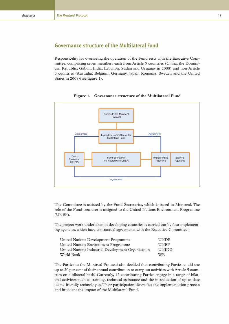
Figure 1. Governance structure of the Multilateral Fund
Parties to the Montreal Protocol
Executive Committee of the Multilateral Fund
Fund Treasurer (UNEP)
Fund Secretariat (co-located with UNEP)
Bilateral Agencies
Implementing Agencies
AgreementAgreement
Agreement
Governance structure of the Multilateral Fund
Responsibility for overseeing the operation of the Fund rests with the Executive Com-mittee, comprising seven members each from Article 5 countries (China, the Domini-can Republic, Gabon, India, Lebanon, Sudan and Uruguay in 2008) and non-Article 5 countries (Australia, Belgium, Germany, Japan, Romania, Sweden and the United States in 2008)(see figure 1).
The Committee is assisted by the Fund Secretariat, which is based in Montreal. The role of the Fund treasurer is assigned to the United Nations Environment Programme (UNEP).
The project work undertaken in developing countries is carried out by four implement-ing agencies, which have contractual agreements with the Executive Committee:
United Nations Development Programme UNDPUnited Nations Environment Programme UNEPUnited Nations Industrial Development Organization UNIDOWorld Bank WB
The Parties to the Montreal Protocol also decided that contributing Parties could use up to 20 per cent of their annual contribution to carry out activities with Article 5 coun-tries on a bilateral basis. Currently, 12 contributing Parties engage in a range of bilat-eral activities such as training, technical assistance and the introduction of up-to-date ozone-friendly technologies. Their participation diversifies the implementation process and broadens the impact of the Multilateral Fund.

14 Preparing for HCFC phase-out: Fundamentals of uses, alternatives, implications and funding for Article 5 countries
Assistance provided to date by the Multilateral Fund (MLF)
Based on the existing global network and programme-development capabilities of the four implementing agencies, the Multilateral Fund has built a capacity enabling it to deliver a programme of up to US$ 200 million annually.
By the end of 2008, the Executive Committee had held 56 meetings (three meetings annually) since the establishment of the Multilateral Fund in 1990.
During these meetings, the Executive Committee has approved the expenditure of over US$ 2.28 billion to support around 5,900 projects and activities in 147 countries, including the preparation of 138 country programmes, technical assistance, training and capacity-building and defrayal of the operating costs of ozone offices in 142 Article 5 countries.
The Multilateral Fund also supports investment projects including the closure of plants producing ozone-depleting substances and the conversion of manufacturing enterprises, large and small, that rely on the use of ozone-depleting substances.
Reporting
The Protocol requires each Party to annually report its production, import and export of each of the chemicals it has committed to phasing out (most countries use no more than four or five of these chemicals).
“Production” is defined as amount produced minus amount destroyed of certain ODSs in a reporting year. “Consumption” is defined as amount of ODSs produced plus imports minus exports. Consumption is a figure calculated from reported amounts of production, imports and exports of a certain ODS in a reporting year. It is not necessarily an amount consumed or usage in the year.
Reports containing data on the production and consumption of ozone-depleting sub-stances by the Parties are reviewed by an Implementation Committee made up of ten Parties from different geographical regions. The Committee assesses the compliance status of countries and makes recommendations to the Meeting of the Parties regarding Parties in non-compliance.
Compliance
Non-compliant Parties participate in the development of plans of action that contain time-specific benchmarks for ensuring their prompt return to compliance.
The Protocol includes trade provisions that preclude Parties from trading in ozone-depleting substances with non-Parties. Related provisions, which have never been explicitly used to preclude trade, have helped the Protocol to achieve near universal participation.

15chapter 2 The Montreal Protocol
Amendments to the Protocol
The Protocol includes a requirement for a regular assessment intended to enable the Parties to make informed decisions on the basis of the most up–to-date information available on science, environmental effects, technology and economics.
The Protocol includes an adjustment provision that enables the Parties to respond to evolving science and accelerate the phase-out of agreed ozone-depleting substances without going through the lengthy formal process of national ratification. It also includes an amendment provision which has facilitated the addition of new chemicals and institutions within the Protocol.
Ongoing development of implementation modality
The rules and procedures governing the implementation of the Montreal Protocol are agreed by the Executive Committee of the Multilateral Fund at its regular meetings, which take place three times a year (see table 6).
Table 6. Recent Executive Committee meetings
Meeting Dates Location
53rd 26 – 30 November 2007 Montreal, Canada
54th 7 – 11 April 2008 Montreal, Canada
55th 14 –18 July 2008 Bangkok, Thailand
56th 8-12 November 2008 Doha, Qatar
57th 30 March – 3 April 2009 Montreal, Canada
Through these meetings, the implementation modality of the Montreal Protocol has evolved to incorporate ongoing developments in technology and experience gained through implementation of ODS phase-out activities around the world.
References
Reference document title Source/Origin
Technical Meeting on HCFC phase-out, 5-6 April 2008, Montreal, Canada, Meeting Minutes
European Commission/ICF
International
Handbook for the International Treaties for the Protection of the Ozone Layer: The Vienna Convention (1985), The Montreal Protocol (1987), Sixth edition (2003) - ISBN: 92-807-2316-2
UNEP

16 Preparing for HCFC phase-out: Fundamentals of uses, alternatives, implications and funding for Article 5 countries
Reference document title Source/Origin
Technology and Economic Assessment Panel: Response to decision XVIII/12, Report of the Task Force on HCFC Issues (with Particular Focus on the Impact of the Clean Development Mechanism) and Emissions Reductions Benefits Arising from Earlier HCFC phase-out and Other Practical Measures, August 2007
UNEP / TEAP
www.unep.fr/ozonaction/
United Nations Environment Programme, Division of Technology, Industry and Economics, OzonAction Branch
UNEP
www.multilateralfund.org/
Multilateral Fund for the Implementation of the Montreal Protocol
Multilateral Fund (MLF)

17
3. Climate change
Some people confuse issues of climate change or “global warming” with the issue of depletion of the ozone layer. These are in fact two separate albeit related issues.
The earth is surrounded by a thin layer of gases, which form the atmosphere. It is the earth’s atmosphere that distinguishes it from other planets in the solar system and cre-ates the conditions necessary for life on land and in the oceans. In particular, it provides oxygen to breathe and maintains surface temperatures which can sustain animal and plant life.
The atmosphere acts to regulate the temperature of the earth by trapping some of the heat that radiates from the sun, but allowing most of it to radiate back into space. The exact composition of the atmosphere dictates how much heat is trapped and how much is radiated.
The composition of the atmosphere has changed over geological time, but at a very slow rate. However, human activities over the last 200 years have measurably changed the composition of the atmosphere through the emission of what are known as greenhouse gases.
Greenhouse gases are gaseous compounds that increase the amount of heat trapped by the atmosphere. The higher the concentration of greenhouse gases in the atmosphere, the higher the earth’s average surface temperature becomes. The rate of global warming (and related climate change) is related to the rate of greenhouse gas emissions.
3.1 The UNFCCC and the Kyoto Protocol
The United Nations Framework Convention on Climate Change (UNFCCC) was agreed in 1992 in Rio de Janeiro and ratified thereafter. Many countries joined the international treaty to begin to consider what could be done to reduce global warming and to work on adaptation strategies to cope with whatever temperature increases are inevitable. More recently, a number of nations approved an addition to the treaty, the Kyoto Protocol, which has more powerful (and legally binding) measures. The UNFCCC secretariat supports all the institutions involved in the international climate change political process.
The Kyoto Protocol
The Kyoto Protocol is an international agreement linked to the United Nations Frame-work Convention on Climate Change. It was adopted in Kyoto, Japan, on 11 December 1997, and entered into force on 16 February 2005. To date, 180 nations have ratified the treaty. The detailed rules for the implementation of the Protocol were adopted at the Seventh Conference of the Parties in Marrakesh in 2001, and are called the “Marrakesh Accords.”

18 Preparing for HCFC phase-out: Fundamentals of uses, alternatives, implications and funding for Article 5 countries
The major feature of the Kyoto Protocol is that it sets binding targets for 37 industri-alized countries and the European Community for reducing greenhouse gas (GHG) emissions. These amount to an average of 5 per cent against 1990 levels over the five-year period from 2008 to 2012. The Protocol did not enter into force until 2001, after an adequate number of ratifications had taken place. To date, the Untied States has not ratified the Kyoto Protocol. The emissions are defined as emissions of six gases (see below) as a total basket.
The major distinction between the Protocol and the Convention is that, while the Con-vention encouraged industrialized countries to stabilize greenhouse gas emissions, the Protocol commits them to do so.
Recognizing that the developed countries are principally responsible for the current high levels of greenhouse gas emissions into the atmosphere as a result of more than 150 years of industrial activity, the Protocol places a heavier burden on developed nations under the principle of “common but differentiated responsibilities.”
The Kyoto mechanisms
Under the Kyoto Protocol, countries must meet their targets primarily through national measures. However, the Kyoto Protocol affords them an additional means of meeting their targets by way of three market-based mechanisms. The Kyoto mechanisms are described below:
Emissions trading
Parties with commitments under the Kyoto Protocol (Annex B Parties) have accepted targets for limiting or reducing emissions. These targets are expressed as levels of allowed emissions, or “assigned amounts,” over the 2008-2012 commitment period. The allowed emissions are divided into “assigned amount units” (AAUs).
Emissions trading, as set out in Article 17 of the Kyoto Protocol (known as the “carbon market”) allows countries that have emission units to spare—emissions permitted them but not “used”—to sell this excess capacity to countries that are over their targets.
Thus, a new commodity was created in the form of emission reductions or removals. Since carbon dioxide is the principal greenhouse gas, people speak simply of trading in carbon. Carbon is now tracked and traded like any other commodity. This is known as the “carbon market.”
The Clean Development Mechanism (CDM)
The Clean Development Mechanism (CDM), defined in Article 12 of the Protocol, allows a country with an emission-reduction or emission-limitation commitment under the Kyoto Protocol (Annex B Party) to implement an emission-reduction project in developing countries. Such projects can earn saleable certified emission reduction (CER) credits, each equivalent to one tonne of CO
2, which can be counted towards
meeting Kyoto targets.

19chapter 3 Climate change
The mechanism stimulates sustainable development and emission reductions, while giv-ing industrialized countries some flexibility in how they meet their emission reduction or limitation targets.
Joint implementation (JI)
The mechanism known as “joint implementation,” defined in Article 6 of the Kyoto Protocol, allows a country with an emission reduction or limitation commitment under the Kyoto Protocol (Annex B Party) to earn emission reduction units (ERUs) from an emission-reduction or emission removal project in another Annex B Party, each equiva-lent to one tonne of CO
2, which can be counted towards meeting its Kyoto target.
Joint implementation offers Parties a flexible and cost-efficient means of fulfilling a part of their Kyoto commitments, while the host Party benefits from foreign investment and technology transfer.
The mechanisms help stimulate green investment and help Parties meet their emission targets in a cost-effective way.
Voluntary carbon market
There is a growing demand for greenhouse gas emission reductions in the United States, Europe and other countries. The voluntary carbon market generally applies to companies, individuals, and other entities and activities, which are not subject to mandatory limitations to offset greenhouse gas emissions.
Companies or governments implement greenhouse gas abating projects including energy efficiency and many other types of projects. The projects create emission reduc-tions (ERs). The owner of the project sells ERs to help finance the project activities.
On the other side, governments, companies or others buy ERs from project activities. Some buy ERs to help satisfy mandatory obligations, others buy ERs to apply toward voluntary commitments to reduce their carbon footprint.
Various standards, certification processes, and emissions registry services exist, but there is no universally accepted standard. Some standards are now widely recognized and accepted as a designation of credibility. Examples include: the Voluntary Gold Standard; the GHG Protocol for Project Accounting; and the Climate, Community and Bio- diversity Project Design Standards.
3.2 Greenhouse gases
The main greenhouse gas is water vapour (H2O), which is responsible for about two-thirds of the natural greenhouse effect. In the atmosphere, water molecules capture the heat that the earth radiates and then re-radiate it in all directions, warming the earth’s surface, before it is eventually radiated back into space. Water vapour in the atmosphere is part of the hydrological cycle, a closed system circulating from the oceans and land

20 Preparing for HCFC phase-out: Fundamentals of uses, alternatives, implications and funding for Article 5 countries
to the atmosphere and back again through evaporation and transpiration, condensation and precipitation. Warmer air can hold much more moisture, so increasing temperatures further intensify climate change.
Other major greenhouse gases are carbon dioxide (CO2), methane (CH4) and nitrous
oxide (N2O) and fluorinated greenhouse gases. These gases are regulated under the Kyoto Protocol.
CFCs and HCFCs are also greenhouse gases, but are regulated by the Montreal Protocol rather than the Kyoto Protocol.
Stratospheric ozone itself is a greenhouse gas. Therefore, ozone depletion has served to mitigate some aspects of climate change, while ozone-layer recovery will add to climate change.
Carbon dioxide
The main contributor to the enhanced (man-made) greenhouse effect is carbon dioxide (CO
2). Globally, it accounts for over 60 per cent of the enhanced greenhouse gas effect.
In industrialized countries, CO2 makes up more than 80 per cent of greenhouse gas
emissions.
There is a finite amount of carbon on earth, which, like water, is part of a cycle—the carbon cycle. This is a very complex system in which carbon moves through the atmos-phere, the terrestrial biosphere and the oceans. Plants absorb CO
2 from the atmosphere
during photosynthesis. They use the carbon to build their tissue, and they release it back into the atmosphere when they die and decompose.
The bodies of animals (and humans) also contain carbon, since they are built from car-bon taken in from plants they eat—or animals that eat plants. This carbon is released as CO
2 when they breathe (respiration) and when they die and decompose. Fossil fuels are
the fossilized remains of dead plants and animals formed over millions of years under certain conditions, and that is why they contain a great deal of carbon. Broadly speaking, coal is the remnant of buried forests, while oil is converted oceanic plant life. (Oceans absorb CO
2 which, in dissolved form, is used by marine life in photosynthesis.)
Many billions of tons of carbon are exchanged naturally each year between the atmos-phere, the oceans and land vegetation. Carbon dioxide levels in the atmosphere appear to have varied less than 10 per cent during the 10,000 years before the Industrial Revolution.
Since 1800, however, concentrations have risen by about 30 per cent, as massive amounts of fossil fuels have been burned to produce energy—mostly in developed countries. Currently, the global population emits more than 25 billion tons of CO
2 into the
atmosphere each year. It is the rate of this emission that is the key challenge.
Recently, European researchers discovered that current concentrations of CO2 in the
atmosphere are higher now than at any time during the past 650,000 years.

21chapter 3 Climate change
Ice cores were extracted at a depth of more than 3 km in the Antarctic ice, which formed hundreds of thousands of years ago. The ice contains air bubbles that provide a history of atmospheric compositions from different ages in the earth’s history. CO
2 can stay in
the atmosphere for 50 to 200 years, depending on how it is recycled back into the land or the oceans.
Methane
The second most important greenhouse gas for the enhanced greenhouse effect is meth-ane (CH4). Since the beginning of the Industrial Revolution, atmospheric methane con-centrations have doubled and contributed some 20 per cent to the enhancement of the greenhouse gas effect. In industrialized countries, methane accounts typically for 15 per cent of greenhouse gas emissions.
Methane is created predominantly by bacteria that feed on organic material in the absence of oxygen. It is therefore emitted from a variety of natural and human- influenced sources, with man-made chemical emissions accounting for the majority. Natural sources include wetlands, termites and oceans. Human-influenced sources include the mining and burning of fossil fuels, livestock husbandry (cattle eat plants that ferment in their stomachs, so they exhale methane and their manure contains it), rice cultivation (flooded paddy fields produce methane, since organic matter in the soil decomposes without sufficient oxygen) and landfills (again, organic waste decomposes without sufficient oxygen).
In the atmosphere, methane traps heat and is 23 times more potent than CO2.
Nitrous oxide
Nitrous oxide (N2O) is released naturally from oceans and rain forests and by bacteria in soils. Human-influenced sources include nitrogen-based fertilizers, burning of fossil fuels and industrial production of chemicals using nitrogen, e.g., in sewage treatment.
In industrialized countries, N2O accounts for around 6 per cent of greenhouse gas emis-sions. Like CO
2 and methane, nitrous oxide is a greenhouse gas whose molecules absorb
heat that is trying to escape into space. N2O is 310 times more potent than CO2.
Since the beginning of the Industrial Revolution, nitrous oxide concentrations in the atmosphere have increased by about 16 per cent and have contributed 4 to 6 per cent to the enhancement of the greenhouse effect.
Fluorinated greenhouse gases
The final group of greenhouse gases is comprised of fluorinated compounds such as hydrofluorocarbons (HFCs), which are used as refrigerants and foam-blowing agents; perfluorocarbons (PFCs), which are emitted during the manufacture of aluminium; and sulphur hexafluoride (SF6), which is used in the electronics industry.
22 Preparing for HCFC phase-out: Fundamentals of uses, alternatives, implications and funding for Article 5 countries
CFCs and HCFCs are also greenhouse gases, but are regulated by the Montreal Protocol rather than by the Kyoto Protocol.
These are the only greenhouse gases that do not occur naturally, but have been developed solely by man for industrial purposes.
Atmospheric concentrations are small; their share in the total of greenhouse gas emissions from industrialized countries is around 1.5 per cent. However, they are extremely powerful; they are 1,000 to 4,000 times more potent than CO
2 and some are
as much as 22,000 times more potent.
HFCs are one of the alternatives to HCFCs in refrigeration, air conditioning and foam blowing. The implications of their powerful greenhouse properties are therefore one factor which must be considered in selecting alternatives and developing phase-out strategies.
3.3 Environmental impact of greenhouse gases
Global warming potential
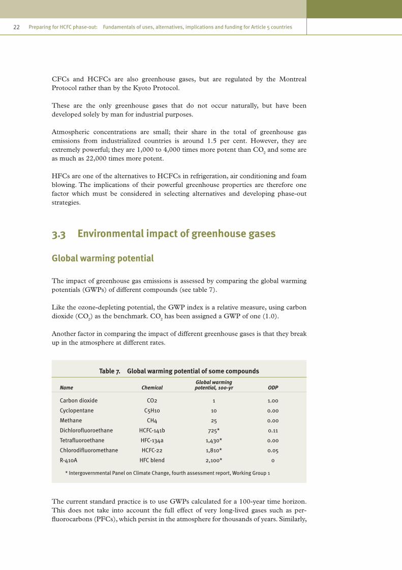
The impact of greenhouse gas emissions is assessed by comparing the global warming potentials (GWPs) of different compounds (see table 7).
Like the ozone-depleting potential, the GWP index is a relative measure, using carbon dioxide (CO
2) as the benchmark. CO
2 has been assigned a GWP of one (1.0).
Another factor in comparing the impact of different greenhouse gases is that they break up in the atmosphere at different rates.
Table 7. Global warming potential of some compounds
Name ChemicalGlobal warming potential, 100-yr ODP
Carbon dioxide CO2 1 1.00
Cyclopentane C5H10 10 0.00
Methane CH4 25 0.00
Dichlorofluoroethane HCFC-141b 725* 0.11
Tetrafluoroethane HFC-134a 1,430* 0.00
Chlorodifluoromethane HCFC-22 1,810* 0.05
R-410A HFC blend 2,100* 0
* Intergovernmental Panel on Climate Change, fourth assessment report, Working Group 1
The current standard practice is to use GWPs calculated for a 100-year time horizon. This does not take into account the full effect of very long-lived gases such as per-fluorocarbons (PFCs), which persist in the atmosphere for thousands of years. Similarly,

23chapter 3 Climate change
integrating over 100 years reduces the assumed contribution of short-lived gases, which last for only part of that period, compared to the impact of CO
2.
Global warming potential can therefore be assessed for different time periods to allow the longer- and shorter-term impact of emissions to be more accurately compared. However, the convention at the present time is to use a 100-year timescale.
Direct and indirect environmental impactAs with ozone-depleting substances, the environmental impact caused by greenhouse gas emissions can occur directly or indirectly, and emissions can take place naturally or as a result of human activities. For example, driving a car powered by gasoline results in direct emissions of CO
2 into the atmosphere through the exhaust from the engine.
Similarly, methane is produced naturally by the decomposition of organic matter in wet-lands or by livestock, and these are examples of direct emissions from natural sources.
Indirect emissions result from the use of electrical energy which is derived from fossil fuels. The impact on greenhouse gas emissions is considered indirect because burning fuel to generate heat or electricity results in CO
2 emissions at the power station and not
at the point of use of the electricity.
Some forms of electricity generation, such as nuclear, hydroelectric, wind and wave, do not result in the release of CO
2. The proportion of electricity generated in this way varies
considerable from country to country. Furthermore, for other forms of generation, the amount of CO
2 released by unit of electricity generated varies depending on the type of
generation (coal, oil, gas, etc.) and the efficiency of the plant. It is therefore impossible to exactly quantify the impact in respect of indirect CO
2 emissions of a certain appli-
cation. However, general assumptions are made on the basis of an average number of kilograms of CO
2 per kWh on a country-by-country, regional or global basis.
Refrigeration and air-conditioning systems which consume significant amounts of electrical power during their lifetimes have a significant indirect environmental impact, as do insulating foams that can save substantial quantities of energy, i.e., reduce CO
2
emissions.
3.4 Overall life-cycle environmental impact
A number of methods of calculating the total effect on global warming have been devel-oped which take into account both the direct and the indirect effects of systems which use and potentially emit greenhouse gases. One such method which is commonly used is the total equivalent warming impact (TEWI) method.
Total equivalent warming impact (TEWI)
The use of TEWI enables designers and contractors to estimate the equivalent CO2
emission into the atmosphere from system leakage (direct emission) and energy consumption (indirect emission).

24 Preparing for HCFC phase-out: Fundamentals of uses, alternatives, implications and funding for Article 5 countries
Based on the high percentage of fossil fuels used in power stations, the average European CO
2 release is around 0.6 kg per kWh of electrical power generated.
Methods of generating power vary, so the global warming impact per kWh will also vary; for example, coal-fired generation will release between 0.6 and 0.8 kg of CO
2 per kWh,
whereas hydro and nuclear power generation has a negligible emission of CO2.
The energy required for the operation of a system has an indirect impact on global warming. The criteria used to estimate the total equivalent warming impact can be summarized as follows:
TEWI = (GWP x La x n) + (Ea x ß x n) (direct) (indirect)
Where:
GWP = global warming potentialLa = leakage rate (kg) per annumn = number of yearsEa = energy consumption (kWh per annum)ß = CO
2 emissions per kWh
TEWI = CO2 (kg)
It is estimated that refrigeration and air-conditioning systems can account for 10 to 20 per cent of total electricity consumption in developed countries.
Research on TEWI has shown that, for most applications, the impact on global warming will be greater from energy consumption than from release of refrigerants.
Current and future technological advances for improving the energy efficiency of refrig-erating and air-conditioning systems will play a decisive role in reducing emissions.
Example of a TEWI calculation
A typical commercial refrigeration system for a cool room comprises a roof-mounted air-cooled condensing unit and two evaporators. The refrigerant selected for the system is R-410A and it contains 50 kg.
The components consuming electricity include:
1 x 6.2kW compressor motor,1 x 0.3 kW condenser fan motor,2 x 0.15 kW evaporator fan motors.
Assumptions:
The average annual refrigerant leakage has been estimated at 10 per cent of the total system volume.
The compressor and condenser fan motors operate for 8 hours each day.

25chapter 3 Climate change
The evaporator fans run around the clock.
Direct global warming impact, calculated for a 20-year time horizon:
Refrigerant GWP: 2,100Estimated annual refrigerant loss: 10 per cent of 50 kg = 5 kgDirect global warming impact for 20 years 2,100 x 5 x 20 = 210,000 kg CO2
Indirect global warming impact, also calculated for a 20-year period:
Daily energy consumption
Compressor and condenser fan motors (6.2+0.3) kW x 8 hours = 52 kWh Evaporator fans: 0.3 kW x 24 hours = 7.2 kWhTotal daily consumption 59.2 kWh
Annual energy consumption 59.2 kWh x 365 days = 21,608 kWhEstimated CO
2 emission per kWh 0.7
Estimated indirect global warming impact: 21,608 x 0.7 x 20 = 302,512 kg CO2
TEWI = leakage + energy consumption 210,000 + 302,512 = 304,612 kg CO2
Life-cycle climate performance (LCCP)
A disadvantage of the TEWI approach is that it does not take into consideration the energy consumed and other emissions related to the manufacture and transportation of the refrigerants or the blowing agents themselves.
The life-cycle climate change performance approach builds on the TEWI approach to provide an holistic approach to estimating all greenhouse gas emissions related to the lifetime operation of a system. Hence, LCCP has become the more accepted methodology.
The life-cycle climate performance (LCCP) approach provides a more accurate estimate of climatic impact in the situation where different alternative fluids such as refrigerants are compared for a given application.
LCCP incorporates all the TEWI factors, and in addition it accounts for the GWP of emitted chemicals used in the process of manufacturing the operating fluids. LCCP also accounts for energy used for production of the operating fluids. The embodied energy is expressed in CO
2-equivalent.
In most cases, manufacturer’s literature quotes annual leakage rates of refrigerants of the order of 4-5 per cent of original charge per year.
However, the actual refrigerant emissions or leakage depend greatly on the standard of installation and the quality and regularity of servicing. It is quite common for poorly maintained systems to consume significantly higher volumes of refrigerants, and qualitative research indicates that 15 per cent of charge is a more realistic figure,

26 Preparing for HCFC phase-out: Fundamentals of uses, alternatives, implications and funding for Article 5 countries
particularly for split systems, where multiple connections and pipe-runs create more opportunities for leaks. Self-contained units manufactured and tested in the factory environment feature negligible leakage rates.
Commercial refrigeration causes more refrigerant emissions of CO2 equivalent than any
other refrigeration application. Centralized systems with long piping circuits have led to large (1,000 to 2,000 kg) refrigerant charges, resulting in large losses when a leak or rupture occurs.
Over the last 10 years, a number of technical improvements have been made to limit refrigerant emissions and their environmental impacts and to reduce the refrigerant charge by developing indirect systems and employing refrigerants with lower GWPs.
It is important to note that refrigerant recovery and recycling and environmentally friendly destruction play an important role in reducing in the life-cycle climate perform-ance of a system, as the overall leakage of a system includes emissions that occur during service and repair.
The following graphs show the LCCP analysis for different refrigerants for a screw chiller and a commercial supermarket system.
Figure 2. LCCP—350-Ton screw chiller
Figure 3. LCCP—Commercial refrigeration (60,000 ft2 supermarket)
10,000,000
8,000,000
6,000,000
4,000,000
2,000,000
0R-22 R-410A
2.9%
97.1%
2.7%
97.3%
Direct CO2 emissions kg CO2e
Indirect CO2 emissions kg CO2e
Refrigerant
LCCP
(Kg
CO2e
)
Source: ADL
25,000,000
20,000,000
15,000,000
10,000,000
5,000,000
0DX Distributed Secondary
loop
50.8
%49
.2%
7%93
%
1.3%
98.7
%
Direct CO2 emissions kg CO2e
Indirect CO2 emissions kg CO2e
Configuration
LCCP
(Kg
CO2e
)
Source: American Refrigeration Institute.

27chapter 3 Climate change
Net environmental impact of insulation foams
In the case of insulation materials for buildings such as polyurethane foam, the environ-mental impact of manufacturing the foam is one factor to be considered, but the overall environmental impact of manufacturing and using foam involves three factors:
Table 8.
Indirect The indirect greenhouse gas emissions associated with the energy used to make the insulation. Referred to often as “embodied or embedded energy”
Negative
Direct The direct impact of losses of the halocarbon blowing agent from the insulation during its manufacture, use, and at the time of disposal
Negative
Indirect The reduction in heating and/or cooling energy used in the building where the insulation is applied and associated reduction of greenhouse gas emissions
Positive
Some experts have claimed that the use of halocarbon-blown foam insulation has a relatively positive impact on climate, with the reduction in emissions related to electrical heating or cooling being greater than the CO
2-equivalent halocarbon emissions.
For typical blowing-agent loss rates and for insulation levels found in high-performance houses, marginal payback times can be in excess of 100 years using halocarbon blow-ing agents, but are only 10–50 years using non-halocarbon blowing agents. With a fixed thickness of insulation, the difference in heating energy savings using insulation with different blowing agents is generally only a few percentage points, in spite of differences in thermal conductivity of up to 66 per cent.
3.5 Relationship between HCFC phase-out and climate change
The choice of an HCFC phase-out technology will have an impact on the environment in a number of ways. Clearly, there will be an environmental benefit related to ozone depletion from the phase-out of ozone-depleting substances, but the global warming impact could be negative, neutral or positive relative to the existing technology depending on a number of factors.
A number of the potential alternatives to HCFCs (HFCs and HFC blends) have higher global warming potentials than HCFCs and their use therefore entails a rise in the direct global warming impact of a system, assuming that leakage rates remain the same. However, direct emissions could be reduced if the amount of HFC used was reduced by reducing leakage.
The other factor to be taken into account is the indirect impact resulting from the energy consumption of the system. If a system is made more energy efficient by using more efficient substitutes, or by changing the operation mode, then fewer CO
2 emissions
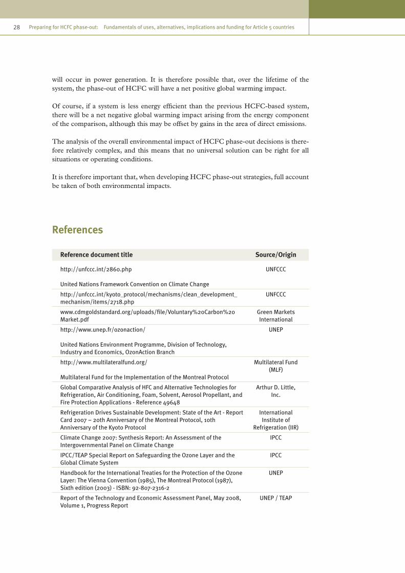
28 Preparing for HCFC phase-out: Fundamentals of uses, alternatives, implications and funding for Article 5 countries
will occur in power generation. It is therefore possible that, over the lifetime of the system, the phase-out of HCFC will have a net positive global warming impact.
Of course, if a system is less energy efficient than the previous HCFC-based system, there will be a net negative global warming impact arising from the energy component of the comparison, although this may be offset by gains in the area of direct emissions.
The analysis of the overall environmental impact of HCFC phase-out decisions is there-fore relatively complex, and this means that no universal solution can be right for all situations or operating conditions.
It is therefore important that, when developing HCFC phase-out strategies, full account be taken of both environmental impacts.
References
Reference document title Source/Origin
http://unfccc.int/2860.php
United Nations Framework Convention on Climate Change
UNFCCC
http://unfccc.int/kyoto_protocol/mechanisms/clean_development_mechanism/items/2718.php
UNFCCC
www.cdmgoldstandard.org/uploads/file/Voluntary%20Carbon%20Market.pdf
Green Markets International
http://www.unep.fr/ozonaction/
United Nations Environment Programme, Division of Technology, Industry and Economics, OzonAction Branch
UNEP
http://www.multilateralfund.org/
Multilateral Fund for the Implementation of the Montreal Protocol
Multilateral Fund (MLF)
Global Comparative Analysis of HFC and Alternative Technologies for Refrigeration, Air Conditioning, Foam, Solvent, Aerosol Propellant, and Fire Protection Applications - Reference 49648
Arthur D. Little, Inc.
Refrigeration Drives Sustainable Development: State of the Art - Report Card 2007 – 20th Anniversary of the Montreal Protocol, 10th Anniversary of the Kyoto Protocol
International Institute of
Refrigeration (IIR)
Climate Change 2007: Synthesis Report: An Assessment of the Intergovernmental Panel on Climate Change
IPCC
IPCC/TEAP Special Report on Safeguarding the Ozone Layer and the Global Climate System
IPCC
Handbook for the International Treaties for the Protection of the Ozone Layer: The Vienna Convention (1985), The Montreal Protocol (1987), Sixth edition (2003) - ISBN: 92-807-2316-2
UNEP
Report of the Technology and Economic Assessment Panel, May 2008, Volume 1, Progress Report
UNEP / TEAP

29chapter 3 Climate change
Reference document title Source/Origin
Report of the Executive Committee of the Multilateral Fund for the Implementation of the Montreal Protocol to the Twentieth Meeting of the Parties - UNEP/OzL.Pro/ExCom/56/63, 24 October 2008
UNEP
DuPont DP-1, Global LCCP Assessment: IEA Conference, 23-24 October 2006, Mary Koban, Senior Technical Service Specialist, DuPont Fluoroproducts
DuPont
World Meteorological Organization, Global Ozone Research and Monitoring Project, Report No. 50, Scientific Assessment of Ozone Depletion: 2006, pursuant to article 6 of the Montreal Protocol on Substances that Deplete the Ozone Layer, February 2007. From Scientific Assessment of Ozone Depletion, 2006
World Meteorological Organization
(WMO)


31
4. Accelerated phase-out of HCFCs
4.1 Introduction
The production and consumption of HCFCs in developing countries, particularly in air conditioning, the refrigeration sector and foam industries, have grown significantly over the past five years, and without action this growth is expected to continue.
Based on 2006 consumption trends, The Multilateral Fund estimates that global pro-duction and consumption of HCFCs could double by 2015, adding to the dual chal-lenges of ozone depletion and climate change. The level of HCFCs and their emissions therefore poses a significant challenge to the reduction of ozone depletion.
In September 2007, the Parties to the Montreal Protocol agreed to accelerate the phase-out of HCFCs, bringing the final phase-out date forward by 10 years for Article 5 countries.
The September 2007 adjustments to the Montreal Protocol oblige Article 5 countries to take action as soon as possible to freeze their baselines in respect of HCFC produc-tion and consumption levels (average consumption and average production for the years 2009-2010) in 2013, and as a first step, to reduce their production and consumption of HCFCs by 10 per cent by 2015.
4.2 Decision XIX/6 of the Parties to the Montreal Protocol
In September 2007, at their Nineteenth Meeting, in Montreal, the Parties agreed in decision XIX/6 to accelerate the phase-out of production and consumption of hydro-chlorofluorocarbons (HCFCs) (see above). The table below shows the accelerated phase-out schedule for Article 5 countries, and the graph shows how this compares to the previous schedule.
Table 9. Revised phase-out schedule for HCFCs in Article 5 countries
Step Year
Baseline 2009-2010
Freeze 2013
10 % reduction 2015
35 % reduction 2020
67.5 % reduction 2025
97.5 % reduction 2030
Average 2.5 % for servicing tail only 2030-2039
100 % 2040

32 Preparing for HCFC phase-out: Fundamentals of uses, alternatives, implications and funding for Article 5 countries
4.3 Decisions of the Executive Committee of the Multilateral Fund
The first meeting of the Executive Committee (ExCom) following adoption of decision XIX/6 was the 53rd meeting; this afforded an opportunity for the Executive Commit-tee to discuss and consider the various issues regarding the practical implementation of decision XIX/6 of the Parties and the work that it would entail. This included the major challenge of developing policies and guidelines and interventions to ensure that Article 5 countries would be able to meet the accelerated HCFC phase-out schedule agreed by the Parties.
Since the Parties to the Montreal Protocol are bound by the Montreal Protocol treaty, the decisions adopted by the Executive Committee effectively determine the objectives of national HCFC phase-out activities and provide the focus of policy, strategy and regulations to be implemented at the national level in order to achieve phase-out within the agreed time frame.
This section provides a summary of the key recent decisions of the Executive Com-mittee that relate to HCFC phase-out in Article 5 countries. Detailed information and downloadable reports of meetings are available from the following sources:
Multilateral Fund (MLF) www.multilateralfund.org/documents.htmwebsite
United Nations Environment http://ozone.unep.org/Meeting_Documents/mop/Programme (UNEP) website
The decisions of the meetings of the Parties and the Executive Committee are numbered according to the number of the meeting at which they were adopted and sequentially according to the agenda of the meeting.
Figure 4. Old and new HCFC phase-out schedules
Page 43 of 216
Since the Parties to the Montreal Protocol are bound by the Montreal Protocol treaty, the decisions adopted by the Executive Committee effectively determine the objectives of national HCFC phase-out activities and provide the focus of policy, strategy and regulations to be implemented at the national level in order to achieve phase-out within the agreed time frame. This section provides a summary of the key recent decisions of the Executive Committee that relate to HCFC phase-out in Article 5 countries. Detailed information and downloadable reports of meetings are available from the following sources:
Multilateral Fund (MLF) website http://www.multilateralfund.org/documents.htm
United Nations Environment Programme (UNEP) website
http://ozone.unep.org/Meeting_Documents/mop/
2008
2010
2013
2015
2019
2022
2025
2029
2032
2040
0%
50%
100%
150%
200%
New schedule Old schedule

33chapter 4 Accelerated phase-out of HCFCs
Eligibility of Article 5 countries for support from the Multilateral Fund
Decision 53/37 (h)
The Executive Committee decided that, in order to receive Multilateral Fund assistance for phasing out the consumption of HCFCs, Article 5 countries must have ratified or acceded to the Copenhagen Amendment of the Montreal Protocol.
Those Article 5 countries with production facilities must have ratified or acceded to the Beijing Amendment of the Montreal Protocol.
The Committee did, however, recognize the delays that some Article 5 countries might face in the ratification or accession processes, and decided to consider providing funding to countries that had not ratified or acceded to the Copenhagen and/or Beijing Amend-ments on a limited basis. Such countries could receive funding for an HCFC survey and preparation of an accelerated HCFC phase-out management plan as long as their gov-ernments committed to ratify or accede to the relevant amendment. No further funding for implementation of activities would be provided until confirmation of ratification or accession had been received.
The guidelines approved for the development of HCFC phase-out management plans also stipulate that Article 5 countries must have in place an appropriate licensing system for HCFCs and HCFC-based equipment as a condition for approving these plans.
HCFC phase-out management plans
Decision 54/39
The Executive Committee approved guidelines for the preparation of HCFC phase-out management plans (HPMPs) and released a funding advance to the implementing agencies to begin HPMP preparations.
The guidelines set out a staged approach that allows the guidelines to be updated as new technologies are developed. The first stage of a country’s HPMP would address achievement of the baseline freeze for HCFCs in 2013 and of the 10 per cent reduction in 2015.
The Committee requested that countries employ the guidelines to develop the first stage of their HPMPs as soon as possible, depending on the availability of resources.
The guidelines also provide an opportunity for countries that choose to implement investment projects in advance of completion of the HPMP, on the understanding that the quantity of HCFC to be phased out under those projects needs to be deducted from the starting point for sustained aggregate reductions in eligible consumption, as set by the HCFC phase-out management plan (HPMP). Countries and implementing agencies were reminded to take account not only of the ozone-depleting potential of HCFCs, but also of the global-warming implications of

34 Preparing for HCFC phase-out: Fundamentals of uses, alternatives, implications and funding for Article 5 countries
alternative substances and technologies, and to exploit any potential financial incentives and opportunities for additional resources (so-called co-financing), in accordance with decision XIX/6.
Given the importance of regulations, legislation and a licensing system covering HCFCs, the funding for HPMP preparation should cover assistance to include HCFC control measures in legislation, regulations and licensing systems, and confirmation that this has been done would be a prerequisite for funding implementation of the HPMP.
Decision 55/13
The Executive Committee approved guidelines and funding for the preparation of HCFC phase-out management plans for Article 5 countries.
The Executive Committee decided that funding for preparatory assistance should be provided to countries to help them prepare HCFC phase-out management plans and that the level of funding would reflect fairness and equity. To that end, the Executive Committee categorized countries based on their reported HCFC consumption.
Further details of funding levels approved for the preparation of HPMPs and invest-ment projects are given in chapter 6. However, it should be noted that countries that have already received funding for the HCFC surveys will have 25 per cent deducted from the fund for preparation of an HPMP, but will have flexibility in utilizing the agreed project preparation funding.
Those countries that had reported zero HCFC consumption should receive US$ 30,000 for the preparation of HPMPs, but could submit requests for additional funding for HPMP preparation if levels of HCFC consumption greater than zero were identified during preparation and subsequently reported under Article 7.
At the 55th meeting of the Executive Committee, funding for the preparation of HPMPs was approved for a large number of Article 5 countries. Some other countries received funding at the 56th meeting. Details of allocations can be found in the reports of the meetings.
Financing of HCFC phase-out
Decision 54/40
The Executive Committee considered a preliminary analysis of all relevant cost consid-erations concerning the financing of HCFC phase-out, including substitute technolo-gies, financial incentives and other environmental benefits and extensively discussed cost considerations of HCFC phase-out.
The Committee agreed that the contact group established to consider the guidelines for the preparation of HPMPs should also address the relevant cost considerations surrounding the financing of HCFC phase-out.

35chapter 4 Accelerated phase-out of HCFCs
The Committee decided to consider, at its 55th meeting in July 2008, a revised version of the HCFC cost consideration document which would take into account any com-ments that members had submitted to the Fund Secretariat by the end of April 2008.
Decision 55/43
The Executive Committee invited bilateral and implementing agencies to prepare and submit project proposals to the Secretariat for various HCFC uses so that the Executive Committee could choose those projects that best demonstrated alternative technologies and facilitated the collection of accurate data on incremental capital cost and incre-mental operating costs or savings, as well as other data relevant to the application of the technologies, on the understanding that the quantity of HCFCs to be phased out under those projects needed to be deducted from the starting point for sustained aggregate reductions in eligible consumption, as set by the HCFC phase-out management plan.
The Executive Committee noted the limited introduction of several of the HCFC alter-native technologies available to date in Article 5 countries, the need to validate them and optimize their use in the light of the local conditions prevailing in Article 5 coun-tries, and the wide variation in costs of replacement equipment and raw materials and, accordingly, decided:
(i) To request the Secretariat to gather technical information related to HCFC phase-out in the aerosols, fire-extinguishers and solvents sectors on an ongoing basis, to review any project in those sectors when submitted and to refer it, as appropriate, for individual consideration by the Executive Committee;
(ii) To consider deferring to its first meeting in 2010 any decision it might wish to take on policies for the calculation of incremental operating costs or sav-ings from HCFC conversion projects, as well as on the establishment of cost-effectiveness thresholds, in order to benefit from the experience gained through review of HCFC phase-out projects as stand-alone projects and/or as compo-nents of HPMPs prior to that meeting.
The Executive Committee agreed that the technical information contained in document UNEP/OzL.Pro/ExCom/55/47 was sufficient to enable preparation, review and submis-sion on a case-by-case basis of a number of stand-alone projects for HCFC phase-out in the foam, refrigeration and air-conditioning sectors.
The Executive Committee also agreed to request the Secretariat to approach other institutions with the objective of identifying individual, regional or multilateral funding mechanisms that might be suitable and compatible as sources for timely co-financing to replenish the Multilateral Fund in order to achieve additional climate benefits, and to provide a further report to a future meeting.
The Executive Committee agreed to consider, at a future meeting, issues relating to whether or not to retire functioning equipment prematurely, once the 2013 and 2015 compliance targets had been addressed.

36 Preparing for HCFC phase-out: Fundamentals of uses, alternatives, implications and funding for Article 5 countries
Assessment of environmental impact
Decision 55/43
The Executive Committee decided to further consider whether an approach of the type outlined in document UNEP/OzL.Pro/ExCom/55/47 provided a satisfactory and trans-parent basis for the prioritization of HCFC phase-out technologies to minimize other impacts on the environment, including on the climate, as originally envisaged in deci-sion XIX/6 of the Nineteenth Meeting of the Parties, and to request the Secretariat to continue with its evaluation in order to report in a more detailed fashion at a subsequent meeting of the Executive Committee.
Current HCFC conversion projects
Decision 55/5
Taking into consideration the information contained in document UNEP/OzL.Pro/ExCom/55/9, on the accelerated phase-out of HCFCs, the Executive Committee decided to urge the countries and the companies involved in ongoing projects for conversion to HCFC-based equipment to consider using the funding approved for conversion to non-HCFC alternatives where possible.
It also decided to request the Fund Secretariat to identify projects where conversion to HCFC-based equipment was still being considered, to assess briefly the feasibility of conversion to non-HCFC alternatives, and to report to the Executive Committee on the matter at the 56th meeting.
Second-stage conversions
Decision 55/43
The Executive committee decided to continue its deliberations on policy relating to sec-ond-stage conversions and determination of the cut-off date for installation of HCFC-based manufacturing equipment, after which incremental costs for the conversion of such equipment would not be eligible for funding, with a view to concluding its consid-eration prior to submission of stand-alone projects, which could commence at the 56th meeting.
HCFC production sector
Decision 55/42
It was generally agreed that the issues identified in relation to the HCFC production sector were extremely complex and differed from those in relation to CFC production, given the effect on other industries, both upstream and downstream. In that context, it was suggested that phase-out strategies should be developed with the involvement of industry.

37chapter 4 Accelerated phase-out of HCFCs
Among other issues highlighted was the need to identify and clarify such elements as linkages to carbon-funding instruments and the repercussions of the use of HCFCs as both controlled substances and feedstocks. The Executive Committee decided that the sub-group on the production sector should not be reconvened at the 55th meeting and that the open-ended contact group should continue to discuss the issues related to the HCFC production sector at the 56th meeting of the Executive Committee, based on document UNEP/OzL.Pro/ExCom/55/45.
Decision 56/64
The Executive Committee continued its discussions on HCFC production sector issues in the open-ended contact group which had initially been set up at the 55th meeting. The contact group was able to make progress and reach consensus on several issues. In preparation for the 57th meeting, the Fund Secretariat was requested to provide a summary of information publicly available on relevant elements of the operation of the clean development mechanism (CDM) and the amounts of HCFC-22 production available for credits as a first step. The Committee also decided to constitute and con-vene the production sector sub-group at the 57th meeting to continue the discussion on HCFC production sector phase-out issues, including: the practices and procedures laid out in decision 19/36; the calculation of HCFC production sector phase-out costs; the encouragement of a synchronized production/consumption phase-out as part of the first HPMP; incentives for early phase-out of HCFC production and/or the provision of disincentives for HCFC production; the requirement for a robust monitoring system, similar to that used for the verification of the carbon tetrachloride (CTC) phase-out, to monitor facilities that had received funding but continued to produce HCFCs for feedstock uses; and other issues. The Executive Committee would consider the issues of cut-off dates [for funding eligibility] for the production sector at a future meeting and the issue of swing plants, i.e., HCFC facilities that used the existing CFC infrastructure, at its 57th meeting.
Demonstration projects
Decision 55/43
The Executive Committee invited bilateral and implementing agencies to submit a lim-ited number of demonstration projects for the conversion of HCFC projects in the refrigeration and air-conditioning subsectors to low-global warming potential (GWP) technologies, to identify all the steps required and to assess their associated costs.
The Executive Committee invited bilateral and implementing agencies, as a matter of urgency, to prepare and submit a limited number of time-specific project proposals involving interested systems houses and/or chemical suppliers for the development, optimization and validation of chemical systems for use with non-HCFC blowing agents on the following basis:
(i) As part of the projects, following the development and validation process, the collaborating systems houses would provide technology transfer and training to a selected number of downstream foam enterprises to complete the phase-out of HCFCs in those enterprises;

38 Preparing for HCFC phase-out: Fundamentals of uses, alternatives, implications and funding for Article 5 countries
(ii) Agencies would collect and report accurate project cost data as well as other data relevant to the application of the technologies;
(iii) In order to be of benefit for the preparation and implementation of the HPMPs, as well as any stand-alone projects, these specific projects would be completed within a period not exceeding 18 months, and a progress report on each of the two implementation phases, as outlined in paragraphs (i) and (ii) above, would be made available to the Executive Committee;
(iv) Bilateral and implementing agencies and relevant collaborating systems houses were encouraged to address the technological issues surrounding prepara-tion and distribution of pre-mixed polyols containing hydrocarbon blowing agents.
Cost structure for determining funding levels for preparation of HCFC investment and associated activities
Decision 56/16
The Executive Committee discussed the remaining aspects of preparation of HCFC phase-out management plans and agreed on a funding structure for the preparation of an overall HPMP in line with the guidelines for HPMPs developed at the 54th meeting (decision 54/39). The Committee defined four components for the HPMP cost struc-ture: (1) assistance for policy and legislation; (2) survey of HCFC use and analysis of data; (3) development and finalization of the HPMP, including its first stage to address the 2013 and 2015 control measures, the latter being akin to a terminal phase-out man-agement plan (TPMP) or a refrigeration service sector plan; and (4) development of investment activities for the HCFC-consuming manufacturing sectors for the first stage of an HPMP, if such activities were necessary.
Funding for the first three elements would be based on a country’s HCFC consump-tion levels for 2007 for all countries except China, in line with decisions taken at the 55th meeting. Funding for project preparation for the fourth element, development of investment activities for the HCFC-consuming manufacturing sectors, would be limited to a maximum level ranging from US$ 100,000 to US$ 400,000, depending on a coun-try’s HCFC consumption for 2007. Funding would be provided for five manufacturing subsectors (air-to-air air-conditioning systems; refrigeration (including all refrigeration, heat pumps and air-conditioning subsectors except air-to-air air-conditioning systems); polyurethane foam; extruded polystyrene (XPS) foam; and solvent uses in manufactur-ing) based on the total number of enterprises to be converted under the first stage of the HPMP in the relevant subsector. The total funding for preparation of subsector plans in each sector should not exceed US$ 150,000.
Criteria were defined for demonstration projects, in accordance with earlier agreements on cost considerations contained in decision 55/43, paragraphs (b) to (f), and a funding structure was agreed based on the number of beneficiaries. Requests for preparation funds would have to include a number of details to enable the Executive Committee to select suitable projects, as described in decision 55/43 (b).

39chapter 4 Accelerated phase-out of HCFCs
The Committee asked the Secretariat to apply the cost structure when assessing the eligibility for funding of the different elements of HPMP preparation, and if necessary to propose to the Executive Committee adjustments to the structure, in particular with regard to investment and associated activities .
References
Reference document title Source/Origin
Report of the Executive Committee of the Multilateral Fund for the Implementation of the Montreal Protocol to the Twentieth Meeting of the Parties: UNEP/OzL.Pro/ExCom/56/63, 24 October 2008
UNEP
Executive Committee of The Multilateral Fund for the Implementation of the Montreal Protocol: fifty-fifth meeting, Bangkok, 14-18 July 2008: UNEP/OzL.Pro/ExCom/55/53, 18 July 2008
UNEP
Executive Committee of the Multilateral Fund for the Implementation of the Montreal Protocol, fifty-sixth meeting, Doha, 8-12 November 2008
UNEP
Executive Committee of the Multilateral Fund for the Implementation of the Montreal Protocol, fifty-fourth meeting, Montreal, 7-11 April 2008
UNEP
Report of the Executive Committee of the Multilateral Fund for the Implementation of the Montreal Protocol to the Twentieth Meeting of the Parties - UNEP/OzL.Pro/ExCom/56/63, 24 October 2008
UNEP


41
5. Developing an HCFC phase-out strategy
5.1 Introduction
At present, there are a number of non-ODP alternatives available for several HCFC uses. However, the suitability of alternatives must be considered in the light of their availability, the maturity of the technologies, cost-effectiveness, energy efficiency, and other environmental considerations including climate. The level of uncertainty regard-ing future technologies for Article 5 countries is therefore relatively high.
On the other hand, the agreement to accelerate the HCFC phase-out requires countries to move quickly to achieve the initial freeze and reduction targets.
The Multilateral Fund has therefore recommended a staged implementation approach to developing HCFC phase-out management plans (HPMPs), whereby the first stage should address all policy and institutional strengthening as well as technical and finan-cial assistance measures required to achieve compliance with the targets of a freeze in 2013 and a 10 per cent reduction by 2015 in all Article 5 countries.
This section introduces the key principles and considerations relating to the develop-ment of an HCFC phase-out strategy and specifically the development of an HCFC phase-out management plan. Specific technical issues are covered in more detail in later sections of this guide.
5.2 Technical feasibility
The current state of alternatives is given in later sections of this guide; however, the technical feasibility of alternative technologies is being established on an ongoing basis. For example, under decision 55/43, bilateral and implementing agencies have been requested by the Multilateral Fund to prepare and submit project proposals involving interested systems houses and chemical suppliers for the development, optimization and validation of chemical systems for use with non-HCFC blowing agents. Similarly, agen-cies have also been asked to submit demonstration projects for the conversion of HCFC projects in the refrigeration and air-conditioning subsectors to technologies with low global warming potential (GWP), to identify all the steps required and to assess their associated costs.
A range of demonstration projects will be undertaken pursuant to this decision, and agencies will collect and report accurate project cost data as well as other data relevant to the application of technologies.
5.3 Availability
Some technologies are already available to replace HCFCs in Article 5 countries, includ-ing long-term and short-term alternatives, which have varying environmental impacts in terms of ozone depletion and climate change.

42 Preparing for HCFC phase-out: Fundamentals of uses, alternatives, implications and funding for Article 5 countries
However, some technologies are currently not yet available or applicable globally. This situation might change as the rate of HCFC phase-out gathers pace.
Availability of technologies can be restricted for practical reasons such as the lack of supply infrastructure for chemicals and materials, or for commercial reasons where intellectual property rights and production licences are controlled by certain chemical companies, making supply prohibitively expensive for certain countries and regions.
In developing the short-term and long-term phase-out strategy, it is therefore very impor-tant to gain an understanding of the technology options currently available to meet the initial freeze and reduction targets, but also to take account of technologies that might not be available at present but could become available in the foreseeable future.
5.4 Local technical capacity and industry practice
In developing a phase-out strategy, it is important that existing and potential future technical capacities and industry standards be assessed.
This is particularly important when considering hydrocarbons (HCs) as potential replacements for HCFCs. Hydrocarbons are flammable, but can and are widely used as refrigerants and foam-blowing agents. However, the safe use of hydrocarbons requires a certain level of technical practice to be in place throughout the industry sector.
Hydrocarbons are widely used in many developed countries and some of the Article 5 countries, but within strictly controlled operating parameters and in industries with mature codes of practice and highly regulated and controlled training and certification schemes for technicians, etc.
In countries with less developed codes and levels of practice, it might be possible to adopt hydrocarbon solutions in specific situations where the operating conditions and service practices are carefully controlled, such as in industrial applications where safety is properly managed and technicians are trained specifically.
In developing long-term HCFC phase-out plans, consideration should also be given to the feasibility of developing technical capacity and industry practice. Where countries would have completed a refrigerant management plan, terminal phase-out management plan (TPMP) or a national phase-out plan (NPP), then, an important factor will be the ability to mobilize and organize existing technical capacity to meet the new phase-out demands.
In countries with relatively well developed technical infrastructure, some further devel-opment of regulations and codes of practice, as well as a suitable training and certifica-tion infrastructure, might make certain technologies more feasible in the medium to long term.
This issue should also be taken into account when assessing the life-cycle environ-mental impact of refrigeration and air-conditioning systems. For example, the use of alternative refrigerants with high GWPs will have a negative impact on climate change

43chapter 5 Developing an HCFC phase-out strategy
if local service and maintenance practice is poor, resulting in high leakage rates. This impact will be reduced where good industry practice and higher levels of technological infrastructure are in place.
These aspects must be considered on a country-by-country basis and even perhaps on a regional basis within countries, where practices in large cities might differ considerably from provincial or rural practices.
A number of enterprises in developing countries have gained considerable experience in dealing with hydrocarbon-based technologies through the implementation of conver-sions of CFC-based manufacturing processes in the refrigeration, foam and aerosol industrial sectors. This experience should be taken into account in developing HCFC phase-out strategies in relation to the choice of technology.
5.5 Economic viability
The issue of economic viability is often the primary concern at the enterprise level. Whilst there might be technical and regulatory incentives to phase out HCFCs, opera-tors are generally reluctant to change if there will be a net negative impact on revenue and profit.
A staged approach to the implementation of HPMPs has the benefit of limiting growth and of eliminating HCFC uses in the near term in areas where substitute technologies are readily available and cost-effective.
Stage one should identify specific activities and projects required to meet the manda-tory phase-out targets until 2015 and to defray their indicative costs, bearing in mind that costs may have to be adjusted in the future once guidelines on incremental costs for HCFC investment projects have been agreed upon.
Cost-effectiveness
In dealing with the phase-out of ozone-depleting substances to date, the Executive Committee has approved cost-effectiveness thresholds for different types of phase-out projects. These thresholds were based on a large volume of historical data on the cost of phasing out 1 ODP kg in the different sectors. The threshold is expressed as a ratio, i.e., project cost in US$ per ODP kg of substance phased out (US$/ODP kg).
It is argued that, since the ODP values of HCFCs are much lower than those of CFCs, the future thresholds in terms of US$ per ODP kg phased out should be higher than those applied to CFC phase-out in the same sectors. One suggestion is to use US$ per kg instead of US$ per ODP kg, as used in the replenishment report.
Only projects with cost-effectiveness ratios equal to or below the approved level were eligible for funding.

44 Preparing for HCFC phase-out: Fundamentals of uses, alternatives, implications and funding for Article 5 countries
Due to lack of experience, at the present time the Executive Committee has not estab-lished appropriate cost-effectiveness thresholds for HCFC projects; however, these are being developed as demonstration projects are approved and implemented. Experience in CFC phase-out will be taken into account. The cost-effectiveness of HCFC phase-out operations is on the 2009 agenda of the Executive Committee.
Additional sources of finance
Decision 53/37 addresses the need to consider financial incentives and opportunities for co-financing. The Executive Committee has, in the past, enabled grant funds from beneficiary enterprises and other financial institutions to be used for co-financing as a means to allow Fund resources to be employed as seed money.
Most recently, the Executive Committee approved chiller demonstration projects on the basis that Fund resources, which were provided on a grant basis, would be co-financed through other funding sources such as the Global Environmental Facility or out of new funds related to climate change or energy conservation, or from other sources.
The funds allocated for the demonstration projects served as seed money allowing coun-tries to gain experience in accessing other non-Multilateral Fund sources of funding.
Alternative forms of incentive programmes, particularly in the end-user sector, have been developed as part of refrigerant management plans and terminal phase-out management plans for CFC phase-out.
HPMPs should therefore address the extent to which the climate change benefits (i.e., net reduction of direct and indirect greenhouse gas emissions) of certain phase-out activities could provide opportunities for co-financing and how such programmes could be implemented. This should include national energy-efficiency initiatives.
The choice of technologies should also take into consideration paragraph 15 of deci-sion XIX/6 to ensure that environmentally safe substitutes and related technologies are transferred to Article 5 countries under fair and most favourable conditions.
5.6 Environmental impact
The choice of HCFC phase-out technology will have an impact on the environment in a number of ways. Clearly there will be an environmental benefit from the phase-out of ozone-depleting substances through the eventual recovery of the stratospheric ozone layer (as explained before, the impact will be positive, but relatively small), but the impact on global warming could be negative, neutral or positive relative to the existing technology depending on a number of factors.
A number (though not all) of the potential alternatives to HCFCs (HFCs and HFC blends) have higher global warming potentials than HCFCs and therefore would bring about a rise in the direct global warming impact of a system, assuming leakage rates remain the same. However, direct emissions could be reduced if systems are made tighter.

45chapter 5 Developing an HCFC phase-out strategy
The other factor to be taken into account is the indirect impact resulting from the energy consumption of the system before and after the HCFC phase-out. If a system becomes more energy efficient, then it will result in fewer CO
2 emissions from power generation.
It is therefore possible that phase-out of HCFC may reduce global warming.
There is evidence of technological developments in recent years resulting in signifi-cant improvement in the energy-efficiency rate (EER) in some non-HCFC refrigeration applications such as centrifugal chillers and air conditioners. Apart from ODS phase-out, the employment of these technologies brings about a reduction in CO
2 emissions.
This might open up an opportunity to combine assistance from the Multilateral Fund with co-financing from dedicated financial environment mechanisms (GEF, CDM), cli-mate investment funds (Clean Technology Fund, Carbon Partnership Fund), voluntary carbon market (Chicago Climate Exchange) and others, if programme timeframes can be synchronized with HCFC phase-out obligations.
Of course, if a system is less energy efficient than the previous HCFC-based system, there will be a negative impact on global warming.
The analysis of the overall environmental impact of HCFC phase-out decisions is there-fore relatively complex, and that means that no universal solution can be right for all situations.
It is therefore important that, when developing HCFC phase-out strategies, full account be taken of other local and national environmental regulations and commitments.
At the 53rd meeting of the Executive committee, it was noted that HCFC phase-out plans should attempt to address overall environmental impact by taking into account climate-change benefits in the selection of alternatives and phase-out strategies.
Therefore, although the current guidelines with respect to cost-effectiveness thresholds are based on ODP values, phase-out plans should also address the potential for max-imizing the benefits of using alternatives that have lower global warming potentials, taking into account energy efficiencies, equipment and climate circumstances.
Some parties have suggested that a conversion policy that would discourage the use of HFC alternatives with high GWPs could be considered. The Multilateral Fund is supporting activities designed to gain further insights in this area, including demonstra-tion projects embodying little or no GWP technology; effective energy conservation measures; establishment of the necessary framework for management, monitoring and awareness-building in the HCFC sectors; and continuing complementary training and capacity-building activities in relevant sectors.
In addition, the Multilateral Fund Secretariat is working on an intermediate climate assessment methodology for technologies based on a ‘functional unit’ approach. This is less specific than the TEWI/LCCP approach outlined in chapter 3, but could pro-vide better insight into the interaction between GWP and energy-related components. Additional consideration may need to be given to adequate storage of banked recovered refrigerants and destruction of recovered refrigerants. These issues are being considered by the Executive Committee of the Multilateral Fund.

46 Preparing for HCFC phase-out: Fundamentals of uses, alternatives, implications and funding for Article 5 countries
The destruction of HCFCs and HFCs should be carried out by a range of certified destruction technologies such as high-temperature incineration, cement kiln, plasma destruction, catalytic destruction, and others. Details of certified technologies are provided in UNEP publications.
References
Reference document title Source/Origin
Refrigeration and Air Conditioning, CFC and HCFC phase-out: Advice on Alternatives and Guidelines for Users
Department for Trade and
Industry, (DTI), UK Government
Draft Guidance Note for Ozone-Depleting Substances, Refrigeration, Air Conditioning and Heat Pumps (CFCs and HCFCs), December 2005
Environmental Protection Agency,
Ireland
Technical Meeting on HCFC phase-out, 5-6 April 2008, Montreal, Canada, Meeting Minutes
European Commission/ICF
International
Refrigeration Drives Sustainable Development: State of the Art - Report Card 2007 – 20th Anniversary of the Montreal Protocol, 10th Anniversary of the Kyoto Protocol
International Institute of
Refrigeration (IIR)
Regulation (EC) No. 842/2006 of the European Parliament and of the Council of 17 May 2006 on certain fluorinated greenhouse gases
Official Journal of the European
Union
Regulation (EC) No. 2037/2000 of the European Parliament and of the Council of 29 June 2000 on substances that deplete the ozone layer
Official Journal of the European
Union
Handbook for the International Treaties for the Protection of the Ozone Layer: The Vienna Convention (1985), The Montreal Protocol (1987), Sixth edition (2003) - ISBN: 92-807-2316-2
UNEP

47
6. Preparing an HCFC phase-out management plan
6.1 Introduction
The overall approach for planning HCFC phase-out in Article 5 Countries, agreed by the Executive Committee, is to develop a detailed plan for meeting the initial freeze and the 10 per cent reduction steps, including selection of the most appropriate currently available technologies, and in parallel to develop an overarching strategy for the entire phase-out process.
It is important to bear in mind that those technologies which might be most appropriate to achieve the short-term phase-out targets might not be the most appropriate ones in the medium to long term when all factors are taken into account.
The long-term strategy should define the overall direction and include a list of key actions the country expects to undertake to achieve the HCFC phase-out.
Such an approach could be outlined in sequential stages that would allow sufficient lead time for remaining policy issues to be resolved at both the Multilateral Fund and the national levels.
Given the existing level of uncertainty regarding the direction of technological develop-ments, a long-term strategy might include options that could be reviewed and amended periodically in the future in line with the actual status of technological development.
However, in some areas where there is already solid experience with some alternatives, phase-out activities may be carried out in the short term in subsectors with already proven substitute technologies. It will also be useful for the international community to carry out some pilot projects to test these technologies and accumulate experience, both for the countries and for the future activities of the Multilateral Fund.
Where pilot projects are planned, they would contribute towards the reduction in HCFC consumption to meet the freeze level in Article 5 countries, and should be presented as part of the overall and short-term strategy within the HPMP.
Stage two of the HPMP plan would address consumption/production of HCFCs beyond the requirements of meeting the freeze and the 10 per cent reduction.
In fact, the preparation of all these plans shows much similarity to the earlier preparation of RMPs and TPMPs.
6.2 Guidelines for HCFC phase-out management plans (HPMPs)
In developing an HPMP, countries and implementing agencies should bear in mind that the objective is to have a document that provides an overall strategy for achieving com-pliance by each Article 5 country concerned and to define specific activities necessary to achieve the control measures envisaged in 2013 and 2015.

48 Preparing for HCFC phase-out: Fundamentals of uses, alternatives, implications and funding for Article 5 countries
The guidelines approved by the Executive Committee (decision 54/39) contain a pre-liminary format and set out standard procedures for the preparation of these plans, while at the same time leaving enough room for countries and agencies to expand and adapt their plans to suit their specific needs.
The following sections provide an overview of these guidelines. The full guidelines for developing HPMPs are included in the appendices to this document and can be found at: www.multilateralfund.org.
General information
This section should include general information, such as the name of the country and its classification in terms of HCFC use, i.e., HCFCs used in servicing only, HCFCs used in servicing and manufacturing and HCFC producer or not.
It should also specify the controlled substances (HCFCs) covered by the measures proposed in the plan, the sectors covered and the duration of the proposal.
General information
(a) A brief country background;
(b) A brief review of activities undertaken so far on CFC phase-out, focusing on lessons learned and how these can be used for the phase-out of HCFCs;
(c) Brief information summarizing the ratification of the Montreal Protocol and its amendments, particularly the Copenhagen, Beijing and Montreal Amendments, including, as necessary, the identification of steps/action plan needed for ratification; and
(d) A brief summary review of projects funded under the Multilateral Fund for CFC compliance and for other substances, including the implementa-tion of RMPs, TPMPs and/or NPPs, where applicable to HCFCs.
Existing policy, legal, regulatory and institutional frameworks
It is important to provide background information on the current regulations relating to ozone-depleting substances in the country, the extent of the existing licensing systems, and whether there are specific regulations that govern the import and export of HCFCs or HCFC-dependent equipment.
Policy Legislation Regulations Institutional framework
(a) A description of the basic ODS legislation and the existing licensing system in place (including, inter alia, how it operates, required licences for import/export, registration of importers/exporters, the existence of a quota system);
(b) Information on how policies related to HCFCs, if any, are being imple-mented at present (e.g., requires registration of importers and a licence to import/export, but no quotas are set);
(c) A description of stakeholder involvement in the policy and regulatory regime. For instance, this component should indicate whether policy interventions such as equipment bans are being considered. In that

49chapter 6 Preparing an HCFC phase-out Management Plan
regard, it should be noted that consultations are needed to ensure the stakeholders’ agreement and buy-in. How these consultations, if any, are undertaken could be described here;
(d) Information on bans of currently controlled ODS-dependent equipment and the relevant regulations for HCFC-dependent equipment, describing how the bans operate or could operate and the time frame for implementation;
(e) A description of other government initiatives in response to the Protocol’s accelerated phase-out of HCFCs; and
(f) A list of any Multilateral Fund CFC projects under which the CFCs have been replaced with HCFCs, including the status of the project and contact details of the enterprise.
Data collection and analysis
Data surveys should be as comprehensive as possible, and should follow the chain of ODS supply from the time when the substance is ordered and imported into the coun-try and passed to distributors, consumers and manufacturers. While it may not be easy to gather information for each facility that uses HCFCs for manufacturing purposes or for each HCFC user, countries are encouraged to provide basic information for known manufacturing establishments using HCFCs and then devise methods of extrapolating data to cover small and medium-sized enterprises (SMEs).This should be based on the actual consumption information gathered as part of the country programme reporting process, and will be essential in developing HPMPs.
Consumption data gathered will need to be verified at plant level prior to approval of stage-one funding or of future stages of the plan.
The plan should describe how data will be collected and stored. It should also describe the methodology for collecting and validating data, including the name of the institutions involved and the sources of data. Countries are encouraged to consider establishing a centralized database maintained by their national ozone unit.
Data sources and references may include, but are not limited to, customs services, indus-try associations, use data from industries, enterprise surveys, and data from compressor manufacturers. Funding should be reduced by 25 per cent for surveys in countries that have already received such funding in order to avoid double counting (decision 55/13).
A review of projects already approved for the conversion from CFCs to HCFCs should provide relevant information such as CFCs phased out and HCFCs phased in.
Further guidance on HCFC surveys is provided in the UNIDO Questionnaire in appendix A.
Data collection
(a) A description of survey methodology and approach;
(b) An HCFC supply scenario: (i) Production (including the identification and description of swing
plants, and a description of new production plants), (ii) Imports, (iii) Exports, (iv) Levels of HCFCs in blends and as feedstock;

50 Preparing for HCFC phase-out: Fundamentals of uses, alternatives, implications and funding for Article 5 countries
(c) HCFC use/consumption: (i) Levels of HCFC consumption, (ii) Sectoral distribution and description of sectors; and
(d) Information on established HCFC infrastructure, looking particularly at those plants that may have been funded under the MLF for conversion to HCFCs, or those plants that have converted on their own. This will assist in establishing information on the extent of HCFC use in the country and the types of potential interventions that may be necessary for phase-out;
(e) Forecasts for HCFC use (refer to the proposed accelerated phase-out schedule for timetable, include unconstrained demand up to baseline date, and beyond);
(f) Validation of data provided in the survey, following existing Executive Committee guidelines; and
(g) Availability of alternatives to HCFCs and prices.
Strategy
The HPMP should describe the overall strategy that will be followed to achieve the targets to attain complete phase-out of HCFCs.
This should include a discussion of policy instruments needed to reduce the supply of HCFCs, such as import quotas and price controls, as well as the country’s plan for their implementation and enforcement. It should also cover the implementation of the short-term alternatives and access to alternative supplies and the steps to be taken to gradually curtail HCFC demand.
The strategy must also give details of how HCFC phase-out plans will be coordi-nated with the country’s climate-change, chemical-management, and energy policies, and identify any national legislation that may prohibit or restrict specific non-HCFC alternatives.
Strategy (a) Description of planned activities: (i) Institutional activities, including industry actions, (ii) Investment projects, and (iii) Capacity-building, including policy analysis and review and
awareness-raising activities necessary; (b) Timetable for implementation, including reductions proposed;
(c) Management of HCFC supply and demand;
(d) Specific activities for the servicing sector;
(e) Specific capacity-building activities for countries without HCFC consump-tion; and
(f) Cost calculation.
Timescales
The strategy should describe a time frame for the implementation of the planned activi-ties based on the country’s actual needs and its current consumption situation. This would also include an assessment of how great a reduction in HCFC consumption can be achieved immediately with little investment but with targeted institutional activities that may be carried out.

51chapter 6 Preparing an HCFC phase-out Management Plan
Refrigeration servicing
For refrigeration servicing, the proposal should describe the strategy to reduce the dependence on HCFCs. This strategy could include measures such as legal and economic incentives and disincentives, training, public-awareness activities, import controls and other sector-specific initiatives.
The Executive Committee has provided assistance for the establishment of national ozone units, development of national legislation and regulations, licensing systems, and recovery and recycling of CFCs.
The HPMPs should also contain a summary review of the implementation of the rel-evant refrigerant management plans, terminal phase-out management plans, national phase-out plans and sectoral phase-out plans and other projects and activities of the Multilateral Fund.
From results gathered during the survey, it should also be possible to establish how the existing system can be used to facilitate HCFC phase-out, and this information should be included as part of the overall phase-out plan.
HCFC recovery and recycling initiatives based on previous experience should also be included, with a view to proposing specific activities taking into account the lessons learned from the past.
A description of additional actions/activities and estimated costs that might be needed to reorient NPPs/TPMPs from focusing on CFCs to addressing HCFCs should also be included.
6.3 Funding
The Executive Committee at its 55th meeting discussed and agreed on the elements of a cost structure for funding the preparation of an overall HPMP in line with decision 54/39. These discussions had been based on document 55/17, annex IV, where the total funding was divided into several components that made up an HPMP as follows:
(a) Assistance for policy and legislation, e.g., to develop new or extend existing legislation regarding HCFCs, products containing HCFCs, quotas and licences;
(b) Survey of HCFC use and analysis of data;
(c) Development and finalization of the HPMP, including its first stage to address the control measures in respect of the targets for 2013 and 2015, the latter being akin to a TPMP or a refrigeration service sector plan; and
(d) Development of investment activities for the manufacturing sectors for the first stage of an HPMP, if such activities are necessary.

52 Preparing for HCFC phase-out: Fundamentals of uses, alternatives, implications and funding for Article 5 countries
At the same meeting, the Executive Committee discussed a funding structure for HPMP preparation which covered only elements (a) to (c) above and approved funding for several countries on this basis.
The funding levels agreed at the 55th meeting are as follows, as reflected in document 56/13:
Table 10.
Group according to consumption patternFunding for above
components (a)-(c)
Countries with zero consumption of HCFCs US$ 30,000
Countries with consumption only of HCFC-22, or consumption below 6 ODP tonnes/year
US$ 85,000
Countries with medium consumption, between 6 ODP tonnes/year and 100 ODP tonnes/year
US$ 150,000
Countries with high consumption, between 100 ODP tonnes/year and 1,200 ODP tonnes/year
US$ 195,000
Countries with a consumption above 1,200 ODP tonnes/year (China only)
Individual consideration
6.4 Investment projects
Based on the HCFC surveys completed for 13 countries and document UNEP/OzL.Pro/ExCom/55/47 (revised analysis of relevant cost considerations surrounding the financing of HCFC phase-out), the Secretariat proposes to define, for the time being, five different manufacturing sectors:
(a) Refrigeration (including chillers); (b) Air-to-air air-conditioning systems; (c) Polyurethane rigid foam; (d) XPS foam; and (e) Solvent uses in manufacturing.
On the basis of these sectors, the Secretariat developed the following structure for the funding of investment activities, taking into account previous levels of project prepara-tion funding for relevant projects, umbrella projects and sector plans, as well as deci-sions on preparation funding for the HPMP adopted at the 55th meeting. The maximum preparation funding for the manufacturing sectors for the preparation of the first stage of an HPMP will be determined by the total number of enterprises to be converted in the relevant sector under the first stage of the HPMP, excluding those enterprises with demonstration projects that may be chosen by the Executive Committee in accordance with decision 55/43.
Table 11.
Number of enterprises covered by investment project Maximum funding
(a) One enterprise to be converted in a manufacturing sector: US$ 30,000
(b) Two enterprises to be converted in a manufacturing sector: US$ 60,000

53chapter 6 Preparing an HCFC phase-out Management Plan
Number of enterprises covered by investment project Maximum funding
(c) Three to 14 enterprises to be converted in a manufacturing sector: US$ 80,000
(d) Fifteen and more enterprises to be converted in a manufacturing sector:
US$ 150,000
(e) The maximum preparation funding for sector plans with perform-ance targets beyond the 2015 control measures can be determined on a case-by-case basis, taking into account the levels established in paragraphs (a) to (d) above.
6.5 Demonstration projects
For demonstration projects, in accordance with decision 55/43, paragraphs (b) to (f), the request for preparation funds should include specification of the country, the sec-tor, a brief description of the project, a statement of the approximate phase-out to be achieved, a reference to the relevant sub-paragraph of decision 55/43, and a descrip-tion of compelling reasons why the Executive Committee should choose this project, as described in decision 55/43, paragraph (b). Funding could be provided up to the following levels:
Table 12.
Number / type of demonstration projects Maximum funding
(a) Stand-alone demonstration projects (55/43) in a manufacturing sector, per project:
US$ 30,000
(b) Umbrella demonstration projects (55/43) with three to 14 benefici-aries in one manufacturing sector, per umbrella project:
US$ 80,000
(c) Demonstration projects addressing 15 or more beneficiaries cannot receive preparation funding for demonstration projects related to decision 55/43, as projects of this size should be part of the HPMP submission preparation.
References
Reference document title Source/Origin
Technical Meeting on HCFC phase-out, 5-6 April 2008, Montreal, Canada, Meeting Minutes
European Commission/ICF
International
Draft guidelines for the preparation of HCFC phase-out management plans incorporating HCFC surveys (decision 53/37 (h)) - UNEP/OzL.Pro/ExCom/54/53, 7 March 2008
UNEP
Report of the Executive Committee of the Multilateral Fund for the Implementation of the Montreal Protocol to the Twentieth Meeting of the Parties: UNEP/OzL.Pro/ExCom/56/63, 24 October 2008
UNEP
Executive Committee of the Multilateral Fund for the Implementation of the Montreal Protocol: fifty-fifth meeting, Bangkok, 14-18 July 2008: UNEP/OzL.Pro/ExCom/55/53 18 July 2008
UNEP

54 Preparing for HCFC phase-out: Fundamentals of uses, alternatives, implications and funding for Article 5 countries
Reference document title Source/Origin
Executive Committee of the Multilateral Fund for the Implementation of the Montreal Protocol, fifty-sixth meeting, Doha, 8-12 November 2008
UNEP
Executive Committee of the Multilateral Fund for the Implementation of the Montreal Protocol, fifty-fourth meeting, Montreal, 7-11 April 2008
UNEP

55
7. Fundamentals of refrigeration and air conditioning
7.1 Introduction
In nature, heat energy always flows naturally from a higher to a lower temperature.
To put it another way, wherever there is a temperature difference between two objects or substances, heat will flow from the object or substance at a higher temperature to the object or substance at a lower temperature. This can be seen in many everyday situations.
For example, a hot cup of tea cools down naturally as the heat in the tea is transferred to the cup and the surrounding air. Eventually, the tea and the cup will reach the same temperature as the surrounding air, and heat transfer will stop as there is no longer a temperature difference between the tea and its surroundings.
Similarly an ice cream will begin to warm up and melt as heat from the surrounding air moves from the air that is at a higher temperature to the ice cream that is at a lower tem-perature. Refrigeration is the process of extracting heat from a space or a substance and moving it somewhere else in order to lower the temperature of the space or substance and to maintain that lower temperature. This means reversing the natural flow of heat and removing heat from a substance or object at a lower temperature to one at a higher temperature.
In a domestic refrigerator, heat is extracted from the space inside the refrigerator cabinet and ejected from the back of the refrigerator into the room where the refrigerator is located. The result is that the temperature of food inside the refrigerator is significantly lower than the temperature of the room, the opposite of what would happen if natural heat flow took place.
In an office air conditioner, heat is extracted from the office space and ejected outside the building into the atmosphere. The result is that the temperature in the office is lower than the temperature outside the building.
The term refrigeration generally refers to an artificial or man-made process for extract-ing heat and lowering temperature, whereas the natural loss or dissipation of heat from objects at a higher temperature is referred to as cooling.
The term air conditioning is generally used to describe systems or appliances that artifi-cially lower the air temperature in a work or living space. However, as the term implies, air-conditioning systems are also used to dehumidify or heat air, depending on the out-side conditions relative to the work or living space. However, this guide is primarily concerned with the refrigeration aspects of air-conditioning systems.
7.2 How do refrigeration and air-conditioning systems work?
Refrigeration and air-conditioning systems are machines or systems of components that remove heat from a space or substance and discharge the heat elsewhere, generally against the natural flow of heat.
56 Preparing for HCFC phase-out: Fundamentals of uses, alternatives, implications and funding for Article 5 countries
The science of cooling
Refrigeration and air-conditioning systems work by employing three important princi-ples that stem from the physical laws that govern the relationship between liquids and gases and in particular determine what happens when a liquid turns into a gas and when a gas turns into a liquid. These so-called phase changes are known as evaporation and condensation.
Principle 1
When a liquid evaporates, it absorbs heat required for the evaporation from its sur-roundings; therefore, an object in contact with an evaporating liquid gives up heat to the liquid and is cooled down.
That is why when we sweat our skin cools down; the energy that is needed for the sweat molecules to evaporate comes from our skin.
The process of evaporation is reversed when heat is removed from a gas; this causes the gas to condense back into a liquid.
Principle 2
Some amount of evaporation will take place in a liquid regardless of the temperature of it surroundings, but the highest rate of evaporation and therefore the maximum cooling effect is achieved when the liquid boils.
For example, if water at room temperature is poured into a heavy metal pan which is also at room temperature, the water will evaporate slowly over a long period of time. This will have a very small cooling effect, as the rate of evaporation is very low and the change in temperature of the container will be unnoticeable.
However, if the same pan is at a temperature of 200°C when water at room temperature is poured in, rapid evaporation will take place and the temperature of the container will fall significantly until all the water has evaporated or until the pan and the water are at the same temperature.
Principle 3
The temperature at which a liquid boils depends on the pressure acting on the liquid; the lower the pressure, the lower the boiling point. For this reason, a kettle of water boils at 100°C at sea level, but the same kettle of water would boil at 65°C at the top of Mount Everest. This is because the air pressure at the top of Everest is much lower than that at sea level.
This principle also applies to the reverse process of condensation, so that the higher the pressure, the higher the temperature at which the vapour can be condensed into liquid.

57chapter 7 Fundamentals of refrigeration and air conditioning
What are refrigeration and air-conditioning systems?
Refrigeration and air-conditioning engineers and designers use these scientific prin-ciples to build systems that move heat from one place to another and thereby reduce the temperature of an object or space. Although these systems vary greatly in size and complexity, they all operate in fundamentally the same way.
Refrigeration and air-conditioning systems bring about the evaporation of a fluid in a certain place where the absorption of heat (cooling) is required. Once evaporated, the fluid is transported to a different place to be condensed back into a liquid, where it rejects heat. The condensed fluid is then returned to the place where it is evaporated to absorb more heat, and so the cycle continues.
The overall result is that heat is moved from the place where the fluid is evaporated to the place where the fluid is condensed.
This cycle might take place in a confined area, such as in a domestic refrigerator, where heat is moved only a very small distance from inside the cabinet to outside the cabinet. In an air-conditioning system for a large building, however, heat has to be moved much greater distances, with the evaporation taking place in rooms and offices and the condensing taking place some distance away, on the roof or outside the building.
Regardless of the separation of the components, the fundamental operation of the system as a whole remains the same.
The fluid used for this process of moving heat from one place to another (sometimes referred to as the working fluid or heat-transfer medium) is called the refrigerant.
Many fluids can be used as refrigerants, but because of the fundamental laws of physics, the cooling effect is greatest when the refrigerant is boiling. This has significant implica-tions for the design of refrigeration systems, because to achieve cooling at low tempera-tures requires liquids that boil at those temperatures and that can be condensed back into liquids at normal temperatures.
For example, to achieve the temperatures required in a normal domestic refrigerator/freezer, a refrigerant with a boiling point of around -20°C and a condensing temperature of around 50°C is required.
Refrigerants are discussed further in chapter 9.
The components of refrigeration or air-conditioning systems
There are many different types of refrigeration and air-conditioning systems, from sim-ple domestic refrigerators and freezers to large cooling systems used in food production and industrial manufacturing. Despite the range of scale and complexity of systems, the basic principles on which they work are the same.

58 Preparing for HCFC phase-out: Fundamentals of uses, alternatives, implications and funding for Article 5 countries
All refrigeration systems use six fundamental components, each of which plays a particular role in the process of moving heat from one place to another.
There are four mechanical or equipment components: the compressor, condenser, expansion device and evaporator; and two principal chemical components: the refrigerant and the oil.
The main mechanical components are linked by refrigerant lines (pipes) to form a circuit around which the refrigerant and oil circulate. Each component performs a step in a cyclical process known as the refrigeration cycle.
Figure 5. Vapour compression refrigeration circuit
Evaporator
Suction line
Liquid receiver
Metering device
CondenserCompressor
Discharge line
liquid line
More complex refrigeration systems incorporate many other components to monitor and control the operation and performance of the systems, and large systems are often formed by connecting multiple compressors, evaporators and condensers in parallel. Larger systems might incorporate a liquid receiver between the condenser and expan-sion device to act as a buffer which ensures that there is always enough refrigerant to serve the evaporator.
Regardless of complexity, however, the fundamental operation of every refrigeration and air-conditioning system is based on these six components.
The vapour compression refrigeration cycle
The vapour compression refrigeration cycle is the most commonly used cycle. However, there are other refrigeration cycles (for example, Stirling and thermo-electric cycles), but these cycles do not use HCFCs and are therefore not considered in this guide.

59chapter 7 Fundamentals of refrigeration and air conditioning
The aim of this section is to explain the components in the most commonly used cycle, as these occur in all HCFC refrigeration systems.
Evaporators
Liquid refrigerant passes into a heat exchanger known as the evaporator. This is gener-ally a long pipe through which the refrigerant flows; it is located in the place where the temperature is to be reduced.
The pressure inside the pipe is such that the refrigerant boils at a low temperature (this is a result of design parameters), absorbing heat in the process and producing a low-pressure vapour.
For example, in a domestic refrigerator, the evaporator is a serpentine-shaped pipe built into the back of the refrigerator or freezer compartment. This is why frost or ice often accumulates inside at the back of the refrigerator, as this surface is the coldest part.
In an office air-conditioning unit, the evaporator is a serpentine or coil of pipe located in the cassette unit mounted on the ceiling or on the wall. Air is blown through the unit and is cooled as it passes over the coil in which the refrigerant is evaporating.
Compressors
The low-pressure refrigerant vapour is drawn out of the evaporator by the compressor. The pipe from the evaporator to the compressor is called the suction line, as it feeds the suction side of the compressor.
The compressor raises the pressure (and temperature) of the refrigerant vapour and discharges the high-pressure vapour to the condenser. The pipe from the compressor to the condenser is known as the discharge or high-pressure line.
Several types of compressors are used in refrigeration and air-conditioning systems. The common types are reciprocating (piston and cylinder), rotary scroll or screw compressor designs.
In a domestic refrigerator, the compressor is housed in a black metal casing at the rear of the unit attached to the base. In an office air-conditioning unit, the compressor or compressors will be located in a separate machine room or possibly outside the building or on the roof.
Condensers
The high-pressure vapour from the compressor carrying the heat from the evapora-tor and heat added by the compressor passes into the condenser. This is another heat exchanger where heat is ejected from the refrigerant into the atmosphere.
Since the pressure of the refrigerant vapour in the condenser is much higher than that in the evaporator, its boiling temperature or condensing temperature will also be higher (see principle 3).The system is designed so that the pressure in the condenser corresponds to a refrigerant condensing temperature which is higher than ambient temperatures.

60 Preparing for HCFC phase-out: Fundamentals of uses, alternatives, implications and funding for Article 5 countries
In other words, the refrigerant’s condensing temperature is higher than that of the sur-rounding air. The refrigerant in the condenser therefore condenses back into a liquid and rejects heat to the surrounding air in the process.
In actual practice, the condenser cools the refrigerant somewhat below the condensing temperature; this is referred to as sub-cooling. This improves the efficiency of the cycle, since it reduces the amount of refrigerant liquid that has to evaporate into a gas in the expansion valve in order to reduce the temperature and pressure of the liquid entering the evaporator. This phenomenon is important to improve system performance.
In a domestic refrigerator, the condenser is the black serpentine pipe attached to the rear of the unit above the compressor. As refrigerant from the compressor passes through the long length of pipe, it condenses, giving out heat into the room. This is why the back of the refrigerator generally feels warm to the touch.
In an office air-conditioning unit, the condenser or condensers, together with the com-pressor, will be located somewhere outside the building so that the heat given off by the condensation process is ejected to the outside air. It is very common to see condensers on the outside walls of buildings and on roofs. They generally contain a fan which blows air across the condenser coil. This allows the coils to be smaller than they would have to be if they relied on natural ventilation.
Expansion devices
The liquid refrigerant then passes back to the evaporator.
However, before entering the evaporator, the pressure of the refrigerant must be reduced to the evaporator pressure in order to allow the refrigerant to boil at low temperature.
For this reason, an expansion device is placed in the line between the condenser and the evaporator, close to the evaporator. The pipe from the condenser to the expansion device is called the liquid line, as it contains liquid refrigerant.
The process of reducing the refrigerant pressure in the expansion device is often referred to as “throttling”. The expansion device can be a manually or automatically controlled valve, an orifice plate or a simple capillary tube.
The low pressure liquid refrigerant then passes into the evaporator, where it boils, absorbing heat from the cold space. This completes the cycle, and heat has been moved from the place that is at a low temperature to the place that is at a higher temperature, and so the cycle continues.
In a domestic refrigerator, the expansion device can be a simple restriction in the form of a capillary tube of properly calculated length, or a “crimp” in the pipe between the condenser and the evaporator.
In an office air-conditioning unit, the expansion device is a valve known as a thermo-static expansion valve, or TEV. This is located in the cassette unit in the office with the evaporator. This type of expansion device modulates the flow of liquid refrigerant into the evaporator according to the air temperature that is desired in the room.

61chapter 7 Fundamentals of refrigeration and air conditioning
Refrigerants
The refrigerant is a key component of any refrigeration or air-conditioning system. It is the “heat transfer fluid”; it absorbs heat on one side of the circuit (in the evaporator) and rejects heats to the atmosphere on the other side of the circuit (in the condenser).
The thermodynamic properties of a refrigerant determine what can be achieved by a refrigeration or air-conditioning system. This includes:
• The evaporating temperature or the lowest temperature that can theoretically be reached;
• The efficiency of the system or how much electrical power is required per amount of cooling;
• The environment in which the system can operate; the maximum local ambient temperature at which the system can provide adequate cooling (related to condenser performance).
Heat transfer only occurs where a temperature difference exists. The temperature differ-ence also depends on the design of the heat exchanger. The refrigerant has to be evapo-rated at a temperature lower than the desired temperature of the space being cooled because heat transfer is not 100 per cent efficient.
The chemical properties of a refrigerant determine its compatibility with other materials and therefore also determine what other components in the system are made of, includ-ing the condenser, evaporator and seals, pipes, gaskets and the oil.
The chemical properties of the refrigerant also dictate any safety considerations which must be taken into account in the design and operation of the system. These are prima-rily the toxicity and the flammability of the refrigerant. More information on types of refrigerant and their application is given in section 7.10.
7.3 Lubricants for refrigeration systems
Oil is an essential element of any refrigeration or air-conditioning system. It is there to lubricate the moving parts of the compressor, which would otherwise not function.
Compressors contain a reservoir of oil which is drawn into the moving parts, but as the oil is also required at the point of seal between the high-pressure side and the low- pressure side, a certain amount passes the seal point and circulates around the system with the refrigerant. When a system is in steady operation, the oil and refrigerant effectively circulate around the system together.
The oil has a considerable impact on the design of the system because it coats the inside of all of the components; this has an effect on the heat-transfer efficiency in the evapora-tor and condenser and can affect the operation of the expansion device.
The oil also changes the thermodynamic properties of the pure refrigerant, and so the system design must be based on the thermodynamic properties of the refrigerant oil mixture.

62 Preparing for HCFC phase-out: Fundamentals of uses, alternatives, implications and funding for Article 5 countries
The chemical properties of the oil are therefore also extremely important from the point of view of compatibility of the oil with the materials and with the refrigerant, but also as they determine how easily the oil and refrigerant mix. Good miscibility is essential to ensure smooth operation of the system.
7.4 Common types of compressors
The compressor is at the heart of the vapour compression refrigeration cycle, and the availability of efficient, durable and economical compressors is essential to the refrigeration and air-conditioning industry.
The differing physical properties of refrigerants mean that the volume of refrigerant, com-pression ratio and discharge pressures vary from system to system. This makes different types of compressors more or less suitable for different applications and refrigerants.
The main types of refrigeration compressors are piston or reciprocating compressors, screw compressors and scroll, rotary vane and centrifugal compressors.
In general terms, scroll compressors are the most efficient, whilst reciprocating com-pressors provide the highest output pressures and can be used also for heavy industrial purposes.
Reciprocating or piston compressors
These compressors achieve high pres-sure levels and are used for commercial purposes and for domestic refrigerators (small reciprocation compressors). Piston compressors are also known as reciprocating compressors.
A reciprocating compressor uses the reciprocating action of a piston inside a cylinder to compress refrigerant. As the piston moves downward, a vacuum is created inside the cylinder. Because the pressure above the intake valve is greater than the pressure below it, the intake valve is forced open and refrigerant is sucked into the cylinder. After the piston reaches its bottom position, it begins to move upward. The intake valve closes, trapping the refrigerant inside the cylinder. As the piston contin-ues to move upward, it compresses the refrigerant, increasing its pressure. At a certain point, the pressure exerted by the refrigerant forces the exhaust valve to open and the compressed refrigerant flows out of the cylinder. Once the piston reaches it topmost position, it starts moving downward again and the cycle is repeated.
Screw compressors
Screw compressors use a pair of helical rotors. As the rotors rotate, they intermesh, alternately exposing and closing off interlobe spaces at the ends of the rotors. When an
UNIDO: Preparing for HCFC Phase-Out
Page 72 of 216
The oil also changes the thermodynamic properties of the pure refrigerant, and so the system design must be based on the thermodynamic properties of the refrigerant oil mixture.
The chemical properties of the oil are therefore also extremely important from the point of view of compatibility of the oil with the materials and with the refrigerant, but also as they determine how easily the oil and refrigerant mix. Good miscibility is essential to ensure smooth operation of the system.
7.4 Common types of compressors
The compressor is at the heart of the vapour compression refrigeration cycle, and the availability of efficient, durable and economical compressors is essential to the refrigeration and air-conditioning industry.
The differing physical properties of refrigerants mean that the volume of refrigerant, compression ratio and discharge pressures vary from system to system. This makes different types of compressors more or less suitable for different applications and refrigerants. The main types of refrigeration compressors are piston or reciprocating compressors, screw compressors and scroll, rotary vane and centrifugal compressors. In general terms, scroll compressors are the most efficient, whilst reciprocating compressors provide the highest output pressures and can be used also for heavy industrial purposes. 7.4.1 Reciprocating or piston compressors
Bank of Reciprocating Compressors
Compressor Pistons
Bank of reciprocating compressors

63chapter 7 Fundamentals of refrigeration and air conditioning
interlobe space at the intake end opens up, refrigerant is sucked into it. As the rotors continue to rotate, the refriger-ant becomes trapped inside the interlobe space and is forced along the length of the rotors. The volume of the interlobe space decreases and the refrigerant is compressed. The compressed refrigerant exists when the interlobe space reaches the other end (male and female) inside a sealed chamber.
The effectiveness of this mechanism is dependent on close-fitting clearances between the helical rotors and the chamber for sealing of the compression cavities.
Scroll compressors
In a scroll compressor, refrigerant is compressed by two offset spiral disks that are nested together. The upper disk is stationary, while the lower disk moves in an orbital fashion. The orbiting action of the lower disk inside the stationary disk creates sealed spaces of varying volume.
Refrigerant is sucked in through inlet ports at the perimeter of the scroll.
A quantity of refrigerant becomes trapped in one of the sealed spaces. As the disk orbits, the enclosed space containing the refrig-erant is transferred toward the centre of the disk and its volume decreases. As the volume decreases, the refrigerant is com-pressed. The compressed refrigerant is discharged through a port at the centre of the upper disk. Scroll compressors are quiet, smooth-operating units with the highest efficiency ratio of all compressor types.
They are commonly used in automobile air-conditioning systems and commercial refrigeration.
Scroll compressors have a lower rate of leakage and are more efficient than others.
Centrifugal compressors
Centrifugal compressors use the rotating action of an impeller wheel to exert centrifu-gal force on refrigerant inside a round chamber (volute). Refrigerant is sucked into the impeller wheel through a large circular intake and flows between the impellers. The
Compressor screws
Scroll compressor

64 Preparing for HCFC phase-out: Fundamentals of uses, alternatives, implications and funding for Article 5 countries
impellers force the refrigerant outward, exerting centrifugal force on the refriger-ant. The refrigerant is pressurized as it is forced against the sides of the volute.
Centrifugal compressors are well suited to compressing large volumes of refriger-ant to relatively low pressures; they have commonly been used for large central chiller installations using CFC-11 or its replacement refrigerant. The compres-sive force generated by an impeller wheel is small, so chillers that use centrifugal compressors usually employ more than one impeller wheel, arranged in series. Centrifugal compressors are desirable for their simple design and few moving parts.
Although there are other types of refrigeration compressors, they are very uncommon.
7.5 Refrigerants
There are many types of refrigerant in common use.
By far the most common HCFC used as a refrigerant is HCFC-22 (also known as R-22). It accounts for around 97 per cent of the total HCFC consumption in the refrigeration and air-conditioning sector in Article 5 countries, according to the recent assessment of the Multilateral Fund.
Most residential and commercial air-conditioning equipment has traditionally operated on HCFC-22.
Large air-conditioning systems or chillers use either high- or low-pressure refrigerants, depending on the application of the chiller and therefore the evaporating temperatures required. Chillers use HCFC-22, but traditionally centrifugal chillers used CFC-11 and CFC-12). Low-pressure chillers have traditionally used CFC-11, whilst high- pressure chillers use HCFC-22 (R-22) and CFC-12 (R-12). There have also been CFC-12 chillers.
HCFC-123 has been used to replace CFC-11 in low-pressure refrigerants, but it will now have to be phased out in line with the accelerated schedule. However, due to its very low GWP (76), relatively low ODP (0.02 – 0.06), and high energy efficiency, this refrigerant is not considered in some countries as a first priority for phasing out.
The refrigerant alternatives for high-pressure chillers (HCFC-22) are HFCs, HFC blends and ammonia. Some of these options can be applied to existing equipment with minor modifications to the systems. Others can only be used with new equipment designed for the specific refrigerant blend.
Intake
Output
Centrefugal compressor

65chapter 7 Fundamentals of refrigeration and air conditioning
Refrigerants for commercial and industrial refrigeration systems are selected on the basis of the evaporating temperature required in the system. The thermodynamic characteristics of HCFC-22 (R-22) make it suitable for a wide range of applications in commercial and industrial refrigeration systems, as it can be used in a wide range of temperature applications.
HCFCs are also used to make a large number of refrigerant blends that have been used to replace CFC refrigerants since the implementation of the Montreal Protocol. HCFC-124 and HCFC-142b are used to make HCFC blends that have been used as CFC replacements.
The focus of phase-out activities in Article 5 countries will be dominated by the replace-ment of HCFC-22, as this represents 97 per cent of all HCFC refrigerants used in these countries.
7.6 Energy consumption
Energy consumption of refrigeration and air conditioning
The vapour compression refrigeration cycle requires energy to compress the refrigerant from evaporator to condenser pressure.
Although it is feasible to power refrigeration systems in a number of ways, the vast majority of systems are powered by electrical energy.
Systems also incorporate fans to circulate air through evaporator coils and condensers, and some systems incorporate pumps which circulate secondary cooling fluids. These pumps and fans also consume electrical power.
The power consumption of a refrigeration or air-conditioning system is an important factor to consider when assessing the environmental impact of the system as a whole, as electricity generation is one of the main sources of CO
2 emissions. It also represents a
significant operating cost.
Energy efficiency
The fundamental laws of fluids, the basic refrigeration cycle and the principal compo-nents described above are the building blocks of any refrigeration or air-conditioning system.
The challenge faced by engineers and designers is to develop the most efficient and effective systems possible that are also commercially competitive in terms of the purchase price and the operating and maintenance costs.

66 Preparing for HCFC phase-out: Fundamentals of uses, alternatives, implications and funding for Article 5 countries
In addition to the physical and engineering constraints determined by thermodynamics and the properties and costs of materials, further constraints and challenges arise from the growing volume of environmental legislation that increasingly governs the use of chemicals and sets minimum energy-efficiency standards.
Energy efficiency is therefore one of the major drivers in refrigeration design today, and considerable research and development is taking place in this field.
The overall efficiency of a refrigeration or air-conditioning system is therefore the useful cooling produced, divided by the total amount of energy consumed:
Efficiency =Useful cooling obtained (kW)
Electrical energy consumed (kW)
7.7 Aspects of refrigeration and air-conditioning design
Terminology
The process of refrigeration is the removal of heat from a cooler substance or space and its movement to a warmer substance or space. As described previously, the refrigeration cycle works because fluids absorb heat from their surroundings when they evaporate, and this principle is at the heart of the refrigeration cycle.
In everyday terms, however, people tend to think of refrigeration as the supply of “cooling” to a substance or space or the lowering of the temperature of a substance or space. Similarly, engineers talk about cooling condensers, although strictly speaking, condensers reject heat from the refrigerant, which warms the air or liquid around it.
The language used to describe refrigeration and air-conditioning systems is relatively technical in nature; detailed system design is outside the scope of this guide, which focuses on fundamentals. However, some basic design concepts are summarized below to help identify systems.
The aim of this section is to explain the fundamentals of the refrigeration and air- conditioning process. However, the concept of supplying “cooling” is readily under-stood and is used in the text of this guide in that sense.
Air-cooled and liquid-cooled systems
Refrigerant condensers can be cooled (or made to reject heat) by air or by a liquid, typi-cally water. Water-cooled systems flow water over the condenser coils to remove heat from the refrigerant, and air-cooled condensers rely on air circulation to remove heat from the coils. Most air-cooled condensers incorporate a fan which increases the air flow over the condenser surface.

67chapter 7 Fundamentals of refrigeration and air conditioning
Water-cooled condensers can be located in plant rooms inside the building or outside, but air-cooled condensers must be located outside.
Direct and indirect cooling
In the basic refrigeration cycle, the evaporator is located in the place where cooling is required. The outside of the evaporator becomes cold and this cools a substance in contact with it.
In a small air-conditioning unit, the air is blown directly over the evaporator coil in the unit. In a domestic refrigerator, the evaporator at the back of the cabinet or below the shelves is in direct contact with the space it is cooling. Both of these appli-cations are defined as direct cooling.
The term direct expansion, or DX, coil is often used to describe a heat exchanger or cooling coil in which refrigerant evapo-rates and which is in direct contact with the air being cooled.
There are situations where, for reasons of convenience, efficiency, safety or economy, it is not appropriate to locate the evaporator where the cooling is required. In this case, fluid in secondary circuits is cooled by the evaporator and is pumped to the place where cooling is required; a second heat exchanger is therefore needed to provide the cooling at the point of use. The fluid used in the secondary circuit is called a coolant or a secondary fluid and is not a refrigerant.
This tends to be the case for larger central refrigeration systems (e.g., in supermarkets) and air-conditioning systems (e.g., in hospitals or office buildings), where it is more effi-cient to distribute cooling over long distances using secondary fluids than to use large volumes of refrigerant.
The term indirect cooling is therefore used to describe systems where the refrigerant evaporator cools fluid in a secondary cooling circuit which in turn supplies cooling to the point of use.
Central and distributed systems
If air conditioning or refrigeration is required in several places within a medium-sized or a large area or building, these requirements can be met either by installing distrib-uted individual systems wherever there is a cooling requirement or by installing a large central system and distributing the cooling. This approach is often more economical, convenient or safer.
Direct expansion coil

68 Preparing for HCFC phase-out: Fundamentals of uses, alternatives, implications and funding for Article 5 countries
In practice, this generally means locating large plant items, including the compressors, heat exchangers, pumps, etc., in dedicated machine rooms and distributing cooling using secondary circuits as described above.
Depending on the range of applications and temperature requirements on a single site, more than one central system might be installed. For example, a factory might have a central system for air conditioning and a second central system providing cooling for manufacturing processes.
Application of chillers in refrigeration systems
A chiller is a machine that incorporates a refrigeration system and a heat exchanger specifically designed to cool or chill a secondary cooling fluid that can be distributed to various locations to provide cooling. Generally, the secondary cooling fluid is water with additives such as corrosion inhibitors and antifreezing agents such as glycol.
Chillers are very commonly used to provide air conditioning in medium- to large-sized buildings, including hotels, large office buildings, shopping malls, hospitals and public buildings. Chillers are also used to provide cooling process cooling in the manufacturing or processing of goods, food and chemicals.
Most chillers are designed for indoor operation, and are located in central plant rooms; however, they can also be placed outside or on roofs in weatherproof housings.
Chillers are precision machines with high initial capital costs and high running costs, so great care is needed in their selection and maintenance.
Air-off or water-off temperature
The term “air-off” or “water-off” temperature refers to the temperature achieved by the air leaving a cooling coil of an air-conditioning system or the temperature of the water (or other fluid) as it leaves a chiller or other refrigeration heat exchanger. These parameters are very important in designing and controlling more complex systems.
The air-off or water-off temperature will never be as low as the evaporating tempera-ture, since heat exchangers are not 100 per cent efficient. In fact, the water-off or air-off temperature is generally significantly higher.
Similarly, air-on or water-on temperature describes the temperature of the air or water as it returns to the heat exchanger. In an air conditioner, this is slightly higher than the temperature of the room or the temperature of the air being drawn into the cooling coil. For a chiller, this is the temperature of the water when it returns from the secondary heat exchanger, having absorbed heat from the point of cooling.
Knowing these temperatures as well as the volume and flow-rate of water or air that is being cooled allows the actual cooling load to be calculated.

69chapter 7 Fundamentals of refrigeration and air conditioning
Cooling capacity (rating)
The cooling capacity of an air-conditioning system is the rate at which it can remove heat energy from the substance or space being cooled. The rate of energy transfer is also referred to as power. The standard metric unit of power is the kW; however, three different unit systems are commonly used to denote the capacity of a system:
Rating system Unit of energy
kW (standard unit of power) 1kW = 1,000 joules per second
BTU/hour (British Thermal Unit) 1,000 BTU/hr = 0.293kW
Ton of refrigeration 1 ton = 12,000 BTU/hr = 3.5168 kW
A BTU is defined as the amount of heat required to raise the temperature of one pound of liquid water by one degree Fahrenheit.
Calorie (symbol: cal) is the amount of heat (energy) required to raise the temperature of one gram of water by 1°C (1 cal ≈ 4.18 J).
The term “ton of refrigeration” was originally derived from the cooling capacity of a ton of ice.
Design performance and actual performance The performance of air-conditioning or refrigeration systems is determined by a number of operating parameters. As described previously, the condensing and evaporating tem-peratures achievable in a system dictate where it can operate and the temperature range it can serve.
Many other parameters will affect the actual amount of useful cooling that is obtained from a system. These include the design of the heat exchangers in the evaporator and condenser and the volumes and flow-rates of air or water being cooled.
The theoretical or design parameters of a system are only what a system can or should be capable of. In small or self-contained systems, it is easy to accurately predict the performance of a system. However, the bigger and more complex a system is, the more difficult it becomes to accurately predict its actual performance.
Detailed knowledge and experience are therefore necessary in order to design large air-conditioning and refrigeration systems, and equally important, skilled technicians and engineers are required to commission them.
7.8 Types of air-conditioning systems
Introduction The vast majority of air-conditioning systems are electrically driven vapour- compression systems, where air in the space to be cooled is drawn over a coil containing the evaporating refrigerant.

70 Preparing for HCFC phase-out: Fundamentals of uses, alternatives, implications and funding for Article 5 countries
There are many varieties of air conditioners ranging in size from 2.0 kW to several hun-dred kW, with refrigerant charges roughly proportional to capacity.
Table 14. Categories of air-conditioning systems
Category Field of application
Small self-contained systems* Single-room cooling
Split systems (non-ducted) Residential and commercial
Split systems (ducted) Residential and commercial
Packaged air conditioners (ducted) Commercial
*Window-mounted and through-the-wall air conditioners
Nearly all air-cooled air conditioners and heat pumps manufactured prior to 2000 used HCFC-22 as the refrigerant. Since then, many non-Article 5 countries have been mov-ing to non-ODP alternatives ahead of their Montreal Protocol commitment dates. It is estimated that approximately 94 per cent of the installed-unit population currently uses HCFC-22 as the refrigerant (Multilateral Fund Secretariat, Technical Options Committee, 2006).
Air-cooled air conditioners and heat pumps generally fall into four distinct categories, based primarily on capacity or application. They come in several different forms and styles, depending on the size required and where it is to be installed:
Small self-contained air conditioners
Small self-contained air conditioners are small-capacity air conditioners in which all the refrigeration-system components are contained within a single package.
These products have cooling capacities typically ranging from 1 to 11 kW, with an average refrigerant charge of 0.25 kg per kW of cooling capacity. The majority of small self-contained air conditioners historically have used HCFC-22 refriger-ant. The overall average charge is estimated to be 0.75kg. (Multilateral Fund Secretariat, Technical Options Committee, May 2008 update)
There are three main configurations: window-mounted, wall-mounted (through-the-wall) or portable. With window- and wall-mounted units, the evaporator is located on the inside of the room and the condenser is located outside; the components are con-nected through a hole in the wall or window. Portable air conditioners are typically mounted on wheels and can be moved from one room to another. The condenser is cooled by air taken from the room and is exhausted to the outside through a flexible
hose which can be placed in an open window.
Basic window air conditioner

71chapter 7 Fundamentals of refrigeration and air conditioning
Small self-contained air conditioners are designed to heat or cool single rooms or small offices. They are a common sight in many countries and can be seen on the sides of many buildings in towns and cities.
These units are manufactured and charged typically in large plants with quality control and leak tests, leading to low leakage rates on the order of 2-3 per cent of the initial charge per year.
Recent data suggests that the global market for these types of air conditioners is declining in favour of split air conditioners.
Split air conditioners (non-ducted)
Split air conditioners are one of the most commonly encountered forms of air conditioning in many parts of the world. They are found in many places and often in homes, offices and small commercial premises.
Unlike small self-contained units, the components of split systems are, as the name suggests, separated. One or more evaporator units are located in the room being cooled, whilst the compressor and condenser are located outside and are connected to the evaporator units via refrigerant lines. The term ductless or non-ducted simply means that the room air is cooled in the room by the fan coil rather than being cooled elsewhere and ducted into the room through vents or grills.
The indoor units which contain the evaporator coil and a fan to circulate the room air through the coil are often referred to as fan-coil units or simply fan-coils. There is generally one fan-coil unit for each conditioned room. The compressor and condenser are generally mounted together and are referred to as condenser units.
Small ductless split air conditioners rated below around 7 kW with a single indoor fan-coil are often referred to as split room air conditioners or mini-splits. Small or mini-split air conditioners are used in homes, small commercial premises and offices where a sin-gle room is to be air conditioned. The fan-coil units can be floor-standing, wall-mounted or concealed.
Larger ductless split systems use exactly the same approach as mini-splits, but involve multiple fan-coil units and possi-ble multiple condenser units. These sys-tems are suitable for larger installations, where more than one room is to be air-conditioned, and for commercial premises such as restaurants, doctors’ surgeries and medium-sized shops and offices.
Wall mounted fan coil unit and external condenser
(Split air conditioner)
Ceiling mounted fan coil unit

72 Preparing for HCFC phase-out: Fundamentals of uses, alternatives, implications and funding for Article 5 countries
Different styles of fan-coil units can be used in different rooms.
The term multi-split refers to larger systems, where multiple indoor units are connected to a bank of outdoor condensing units, located either on the roof or in a central plant room serving a larger area or a whole building. This approach is often used for larger premises, such as medium-sized office buildings, where perhaps a dozen or more indoor units serve separate living or working spaces.
The vast majority of non-ducted air conditioners manufactured prior to 2000 used HCFC-22 refrigerant with an average HCFC-22 charge of approximately 0.25 to 0.30 kg per kW of cooling capacity. The global average HCFC-22 charge is estimated to be about 1.2 – 1.3 kg per system.
These systems are normally produced in large manufacturing plants as well, with the associated quality control and leak tests. However, the systems are installed on site using pre-charged lines and connectors, which often leads to a higher average leak rate for these systems compared to self-contained units.
Non-ducted split air conditioners use hermetic rotary, scroll or reciprocating compressors.
Split air conditioners (ducted)
Ducted air-conditioning systems supply cooled or conditioned air to multiple rooms in a building using a network of ventilation ducts that are built into the fabric of the building. Ducts often run horizontally in ceiling voids and vertically in wall cavities or specially constructed service shafts.
In split-ducted air conditioning, the evaporators or cooling coils are located in the air ducts instead of in the room where the cooling is required. Central fans draw air through the duct network, and it is cooled as it passes through the cooling coils.
The condensing units (compressor/condenser) are located outside the building or on the roof, and are connected to the cooling coils by flexible refrigerant lines. Generally, a single condensing unit will serve several cooling coils.
Ducted split systems are typically found in large residential buildings, where the air ducts supply each room or small zones within commercial or institutional buildings. Residential systems generally use the same duct system to supply heating to rooms during the winter months.
The refrigerating capacity of such systems is generally between 5 and 18 kW, and the average system has a capacity of around 11 kW and contains around 3.25 kg of HCFC-22.
The drive for greater energy efficiency in many countries has led to new system designs with increased heat-exchanger surface areas. As a consequence, the refrigerant charge per kW of cooling capacity must also be increased.
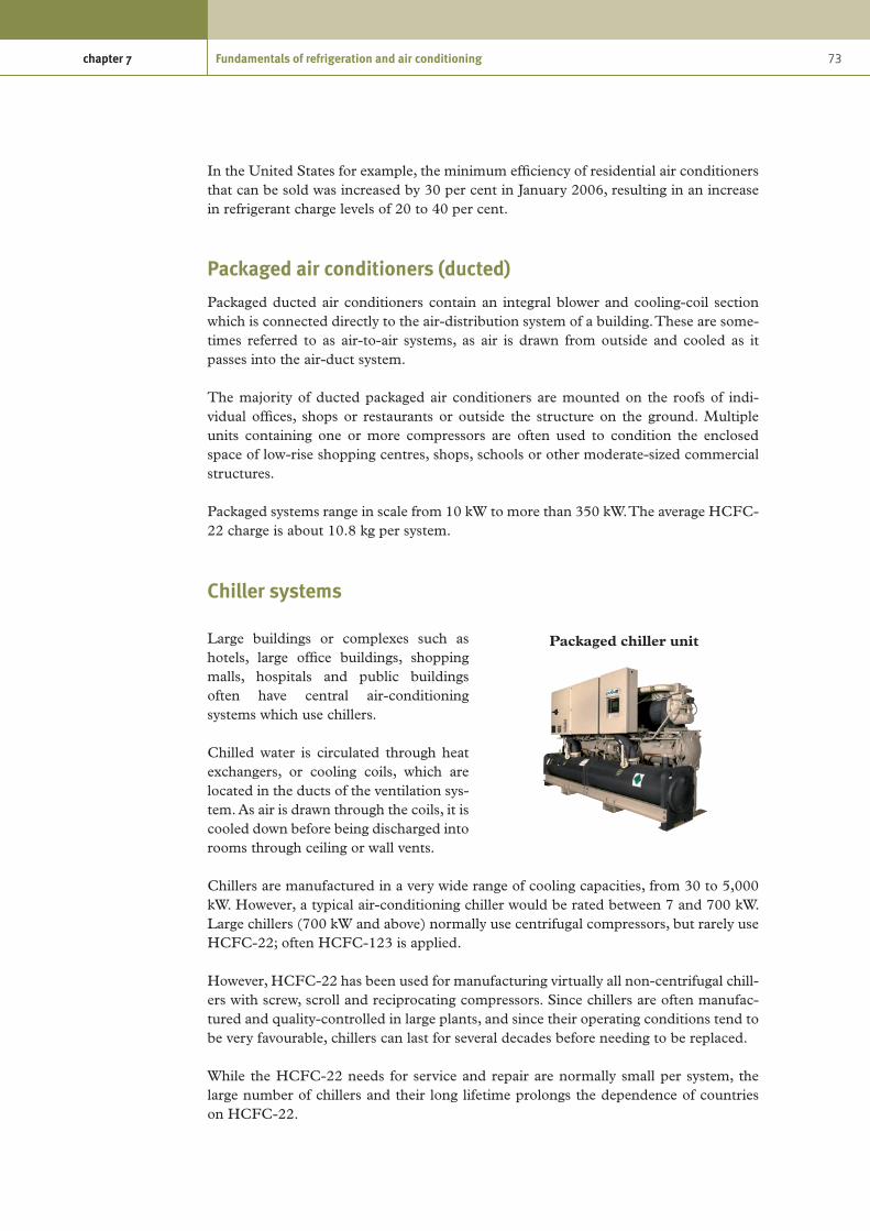
73chapter 7 Fundamentals of refrigeration and air conditioning
In the United States for example, the minimum efficiency of residential air conditioners that can be sold was increased by 30 per cent in January 2006, resulting in an increase in refrigerant charge levels of 20 to 40 per cent.
Packaged air conditioners (ducted)
Packaged ducted air conditioners contain an integral blower and cooling-coil section which is connected directly to the air-distribution system of a building. These are some-times referred to as air-to-air systems, as air is drawn from outside and cooled as it passes into the air-duct system.
The majority of ducted packaged air conditioners are mounted on the roofs of indi-vidual offices, shops or restaurants or outside the structure on the ground. Multiple units containing one or more compressors are often used to condition the enclosed space of low-rise shopping centres, shops, schools or other moderate-sized commercial structures.
Packaged systems range in scale from 10 kW to more than 350 kW. The average HCFC-22 charge is about 10.8 kg per system.
Chiller systems
Large buildings or complexes such as hotels, large office buildings, shopping malls, hospitals and public buildings often have central air-conditioning systems which use chillers.
Chilled water is circulated through heat exchangers, or cooling coils, which are located in the ducts of the ventilation sys-tem. As air is drawn through the coils, it is cooled down before being discharged into rooms through ceiling or wall vents.
Chillers are manufactured in a very wide range of cooling capacities, from 30 to 5,000 kW. However, a typical air-conditioning chiller would be rated between 7 and 700 kW. Large chillers (700 kW and above) normally use centrifugal compressors, but rarely use HCFC-22; often HCFC-123 is applied.
However, HCFC-22 has been used for manufacturing virtually all non-centrifugal chill-ers with screw, scroll and reciprocating compressors. Since chillers are often manufac-tured and quality-controlled in large plants, and since their operating conditions tend to be very favourable, chillers can last for several decades before needing to be replaced.
While the HCFC-22 needs for service and repair are normally small per system, the large number of chillers and their long lifetime prolongs the dependence of countries on HCFC-22.
Packaged chiller unit

74 Preparing for HCFC phase-out: Fundamentals of uses, alternatives, implications and funding for Article 5 countries
Table 14.
Chiller type Capacity range (kW)
Scroll and reciprocating water-cooled 7 - 1,600
Screw water-cooled 140 - 2,275
Positive displacement air-cooled 35 - 1,760
Centrifugal water-cooled 210 - 30,000
Centrifugal air-cooled 420 - 1,150
7.9 Heat pumps
Heat pumps are systems that can use the principles of the refrigeration cycle in reverse to extract heat from a source at a lower temperature and move it to a source at a higher temperature. Instead of the evaporator side of the system being in the place that requires cooling, the condenser side of the system is in the place that requires heat.
For example, a domestic heat pump extracts heat from the outside air during the winter months and rejects it inside a room which is at a higher temperature. The condenser rejects heat inside and the evaporator absorbs heat outside. In this example, heat moves in the opposite direction from that of an air conditioner in the summer, which extracts heat from a room and rejects it to the outside air, which is warmer than the room. In both these situations, the system moves heat in the opposite direction to that which would occur naturally.
Most heat pumps are designed to provide air-off or water-off temperatures of 43ºC to 60ºC, depending on the design of the system.
Although some systems are configured for heating only, reverse-cycle heat pumps use an electrically operated reversing valve to change the direction of refrigerant flow within the system so that the system is able to deliver both heating and cooling as desired. Heat pumps can therefore be used to supply cooling in the winter and heating in the summer. This is particularly useful in countries which have relatively high seasonal temperature variations.
Heat pumps can be more efficient than traditional heating systems, as the quantity of heat provided is more than the power consumed to run the system. Modern systems also allow a significant quantity of the electrical energy that drives the heat pump to be returned to the building as useful heat. Useful heat can be found in the air outdoors and in the ground, and it is present in water, rivers, lakes and the sea. Even on the coldest winter days, sufficient heat is present to warm homes and offices.
All but the largest industrial systems are hermetically sealed and pressurized, thereby reducing noise, space and heat losses.
7.10 Types of refrigeration systems
Refrigeration has a wide range of uses and applications. Refrigeration systems can be categorized into three areas, namely, commercial refrigeration, industrial refrigeration and transport refrigeration.

75chapter 7 Fundamentals of refrigeration and air conditioning
Commercial refrigeration
According to the definitions adopted by the Multilateral Fund every use of refrigeration other than those defined as industrial, chiller, air-conditioning, transport or domestic is considered to be commercial refrigeration.
The majority of commercial refrigeration equipment is used to produce beverages, pre-serve chilled and frozen foods, cool drinks and store foods at the appropriate tempera-tures. Refrigerated equipment is found in supermarkets, convenience stores, restaurants, hotels and other establishments.
To maintain adequate food quality, stor-age temperatures must be maintained accurately, and in many countries stor-age temperatures are controlled by reg-ulations. Two levels of temperature are defined: medium temperature for the preservation of fresh food and storage of beverages, and low temperature for frozen products.
Chilled food is normally stored at tem-peratures between 1°C and 14°C. This requires an evaporating temperature in the refrigeration system between -15°C and +1°C. Most frozen products are stored between -12 and -20°C, requir-ing evaporating temperatures of -35 to -40°C.
Commercial refrigeration equipment can be subdivided into the following broad catego-ries: stand-alone equipment, condensing units and centralized refrigeration systems.
Stand-alone equipment
Stand-alone refrigeration systems have all their components integrated into a single piece of equipment which is produced and typically charged in the manufacturing facil-ity. They are also called plug-in systems, as they can be delivered to the point of use and simply plugged into a suitable electrical supply. This category of equipment includes commercial-sized refrigerators and freezers, water coolers, ice-cream freezers, ice- making machines and food-display cabinets.
Prior to the advent of the Montreal Protocol, the majority of stand-alone equipment used CFC-12 as the refrigerant. HCFC-22 was adopted by some manufacturers as an alternative and is still widely used in Article 5 countries.
This type of equipment is extremely widely used and is visible in almost every town and city throughout the world. The market for this type of equipment continues to grow steadily as food and beverage supply chains continue to develop.
Chilled food cabinet

76 Preparing for HCFC phase-out: Fundamentals of uses, alternatives, implications and funding for Article 5 countries
A lot of smaller stand-alone equipment used for commercial purposes such as wine-coolers, professional kitchen refrigerators and freezers, hotel mini-bars, ice-cream cabi-nets, water coolers, ice machines, and vending machines are based on the same techno-logy as domestic refrigerators and freezers. In the vast majority of cases, these appliances have traditionally used CFC-12 refrigerant and have already been converted to alterna-tive non-ODP refrigerant, mostly to HFC refrigerants.
In addressing phase-out alternatives (chapter 9) this guide therefore only focuses on larger commercial equipment using HCFC-22.
Condensing units
The term condensing unit is used to describe a split refrigeration system which is made up of one or two compressors, a condenser and a refrigerant receiver assembled into a unit which is located in a different place to the evaporator, gen-erally outside the building, where the condenser can be cooled by outside air. Liquid refrigerant is fed to the evapora-tor in the cooling equipment by refriger-ant lines (This is similar in principle to a split air-conditioning system). The cool-ing equipment can be food-display cases, cold rooms or other cooling equipment.
Systems employing condensing units are very common in all Article 5 countries and are used to supply a range of cooling equipment, but primarily cold stores and food-display cases. They are typically installed in shops such as bakeries, butcher shops and conven-ience stores, and they are often also used in smaller supermarkets, where several con-densing units are installed to serve multiple display cases and cold rooms. This approach is used to provide combined cooling capacities of up to 50 kW. However, the use of several condensing units is less energy-efficient than the installation of one specifically designed centralized system. A centralized system, on the other hand, requires compres-sors of larger capacity, and more design and engineering know-how.
Condensing units are normally pre-manufactured in medium to large quantities, and they are generally charged with refrigerant. After delivery, the units can be connected by a refrigeration technician to the cooling equipment and they are ready for use.
The use of condensing units is a preferred solution for many end users in Article 5 countries because the technology is rela-tively simple and easy to install and main-tain, and such units are also locally avail-able in most countries. Another major advantage of condensing units is that they are relatively inexpensive compared to centralized systems.
Basic condensing unit
Refrigerated display case

77chapter 7 Fundamentals of refrigeration and air conditioning
HCFC-22 remains the refrigerant of choice for manufacturing condensing units in Article 5 countries.
Centralized systems
Centralized systems are similar to condensing units, but instead of having one condens-ing unit for each cooling appliance, the central unit serves several or many parallel sets of cooling appliances. Centralized systems contain several compressors (often in racks) and can supply different temperature levels to different cooling units, i.e., chilled-food cabinets at 4°C and freezers at -18°C.
Centralized systems are particularly common in medium-sized and large supermarkets, where the increased efficiency compared to having multiple condensing units gives rise to significant energy-cost savings.
HCFC-22 is commonly used in central-ized systems, but in comparison to con-densing units, the level of complexity of the installation and the high number of refrigerant line connections means that there is a higher potential for refrigerant leaks. The level of technical know-how required for good quality installations is therefore significantly higher.
Two main configurations are used in large installations such as supermarkets: direct and indirect systems.
Direct systems are more widespread. The refrigerant circulates from the machinery room to the sales area, where it evaporates in heat exchangers in display cases, and then returns in vapour phase to the suction port of the compressor racks. The supermarket cold rooms are also cooled in the same way.
In the machinery room, racks of multiple compressors are installed with common suction and discharge ports, and each rack is usually associated with an air-cooled condenser. Specific racks may be dedicated to low temperature and others to medium temperature, with a common connection for each level of temperature.
Indirect systems use a primary heat exchanger to cool a heat-transfer fluid, like glycol or brine (also known as second-ary fluid or coolant), which is pumped to the display cases or other cooling units, where it absorbs heat, and then returns to the primary heat exchanger.
Centralized supermarket refrigeration
Central refrigeration system

78 Preparing for HCFC phase-out: Fundamentals of uses, alternatives, implications and funding for Article 5 countries
This approach reduces the amount of primary refrigerant required in the system, as the refrigeration system is contained in the plant room and the refrigerant does not have to be piped to every cooling unit.
Industrial refrigerationIndustrial refrigeration systems are based on the same principles as air-conditioning and commercial refrigeration, but are generally large-scale and specifically designed for a particular application. The design, installation and commissioning of industrial refrigeration systems require advanced technical skills. Cooling capaci-ties in the industrial subsector vary from 10 kW to 10 MW, with typical evaporat-ing temperatures ranging from -50°C to +20°C.
There is some overlap in the definitions of industrial and commercial refrigeration at the lower end of the industrial capacity scale, in applications for shops, restaurants and insti-tutions. In these cases, industrial systems are defined by the complexity of the design and the nature of the installation. There is also some cross-over with the air-conditioning sector, where a few buildings are served by custom-designed central chilling systems which have more in common with industrial systems than with the typical standardized air-conditioning equipment.
However, most industrial refrigeration is used in what are known as the process industries. These include food processing, such as brewing; the dairy and soft-drinks industries; cold storage and distribution of food; and chemical, petrochemical and pharmaceutical manufacturing. For this reason, industrial refrigeration is sometimes referred to as process cooling. Other niche applications include ice rinks and indoor ski slopes.
The industrial refrigeration sector generally does not include mass-produced or batch-produced packaged equipment, nor does it cover larger standard equipment such as packaged water chillers.
A particular aspect of industrial refrig-eration which sets it apart from smaller refrigeration systems is the type of con-densers used, or more accurately, the way in which the condensers are cooled. Tra-ditionally, evaporative cooling systems such as evaporative condensers or cooling towers have been used.
Recent increases in utility charges for water and the cost of water treatment, coupled with an increased incidence
Industrial refrigeration
Roof-mounted air-cooled condenser

79chapter 7 Fundamentals of refrigeration and air conditioning
of legionella, have encouraged the use of air-cooled condensers. However, air-cooled condensers reduce the efficiency of the system, require more space for the installation and tend to operate at higher noise levels than evaporative equipment.
The most commonly used refrigerants in industrial applications are ammonia (R-717) and HCFC-22. In non-Article 5 countries, where CFCs have already been phased out and HCFCs are severely restricted, most industrial refrigeration systems use ammonia (R-717) as the refrigerant. In Article 5 countries where national regulations still permit the use of HCFCs, they are preferred to ammonia (R-717).
Industrial refrigeration is used to extend the shelf life of foodstuffs, but it can also con-trol the rate of reactions (for example, in brewing, malting or chemical plants) or it may prepare the product for processing (for example, chilling of meat or fish prior to cut-ting). In some cases, such as manufacturing of ice cream or margarine, the method of refrigerating the product is an essential part of the production process.
Most industrial applications use direct systems, where the refrigerant evaporator pro-vides cooling at the point of use. At higher temperatures, indirect systems can be used to distribute cooling to the point of use using water/glycol or brine solutions. This allows the primary refrigeration circuit to be contained within a machinery room.
For lower temperature applications, operating below –15°C, the viscosity of the second-ary fluid usually makes the pumping cost of these indirect systems excessive.
Considerations that would tend to predicate a direct system include emphasis on low capital cost and emphasis on operating efficiency. Where reduction of refrigerant charge is a priority, for example, to reduce the possibility of large refrigerant losses for reasons of public safety or product protection, secondary systems are more common.
Food processing
The global annual chilled food market has been estimated to be about 350 mil-lion tonnes, and this is estimated to be growing at 7 per cent per annum.
The importance of the cold chain has been a factor in the economic develop-ment of Article 5 countries for many years. For this reason, most refrigera-tion in chilled-food factories takes place under air-temperature control to ensure that product life is not impaired during processing. Where there is a large fresh-air input to a processing area, most of the heat load may be in refrigerating the ambient air in summertime.
The same applies to fruit and vegetable storage facilities, where the build-up of off-gases from the product must be controlled in order to inhibit premature ripening.
Process cooling

80 Preparing for HCFC phase-out: Fundamentals of uses, alternatives, implications and funding for Article 5 countries
Significant heat loads will also be found in chillers for cooling cooked products imme-diately after the cooking process. Again, the main objective is to ensure product quality and long life.
Refrigeration equipment is also used in the production of ice in tube, plate or flake form. In most cases, ammonia is used as the refrigerant in larger ice-making systems, although HCFC-22 is still in operation.
There has been a significant increase over the last 15 years in the amount of prepared foods in the chilled market, including sandwiches, salads, fruit salad and cooked meats. There has also been a rapid expansion in the variety of chilled produce on offer in many Article 5 countries.
Food preservation—freezing
Large volumes of fish and meat are frozen either at the source (abattoir, fishing vessel or port) or after preparation or processing into food products. Frozen food must be chilled to achieve a core temperature of -18°C.
There are several methods of freezing food, and the most appropriate process depends on size, shape and packaging. Smaller items are generally frozen using tunnel or spiral freezers. Larger boxed products will either be put on pallets and blast-frozen or processed in boxes in large plate freezers.
Spiral, tunnel and blast freezers are usually operated with an evaporating temperature of about -40°C.
Smaller freezers with a capacity of 50 kW or less tend to use HCFCs in Article 5 countries and North America.
Larger freezers (50 kW to 200 kW) more commonly use ammonia, which gives improved energy efficiency and reduced leakage rates.
Cold storage
Cold storage refers to stores or chambers that maintain goods in a temperature range from –30°C to +15°C. Cold stores can vary in size from 100 m3 to 100,000 m3, rising to facilities with chambers. Small cold stores might have a ceiling height of 3-4 m, whereas in larger chambers, the height may be up to 12 m. The height of the cold store is only limited by the reach of a forklift truck for placing pallets in racked storage.
Smaller rooms are often served by stand-alone systems using CFC, HCFC or HFC in commercial condensing units, but in food production facilities, they may also form a side load on a large industrial freezer plant.
Spiral freezer

81chapter 7 Fundamentals of refrigeration and air conditioning
In small cold stores, the heat load is dominated by air and moisture ingress from the doors. This load can be as much as 50 W/m3. As the chamber size increases, the effect of air ingress is reduced, and a typical large facility has a load of about 12 W/m3.
Process refrigeration
The process industries include chemical production plants, petrochemical sites, phar-maceutical plants and the oil and gas industries. Refrigeration is primarily used for tem-perature control of heat-transfer fluids. At high temperatures, water is most commonly used, and brine or glycol can be used for medium-temperature applications; however, for very low temperatures, and where there is a risk of reaction with process fluids in the event of a leak, other fluids may be used.
Refrigeration is also used in process industries for the production of ice for use in chemi-cal reactions. This is usually in the form of flakes or tubular pieces which can be auto-matically harvested, stored and transported. The ice is usually added to reactor vessels to control the rate of reaction, so large quantities are required over a short period of time.
The ice plants are typically far larger than those found in the food industry, and usually use ammonia as the refrigerant. Flake ice is also used in very large quantities for con-crete cooling on large civil-engineering projects, where it is added to the concrete batch during mixing to avoid overheating and maintain high quality.
Liquefaction of gases
The vapour compression refrigeration cycle can be used to achieve temperatures as low as -170°C for the liquefaction of gases such as carbon dioxide, chlorine, hydrocarbons and natural gases.
Liquefaction of cryogenic gases such as oxygen, air, nitrogen, hydrogen and helium is achieved in a different way, although vapour compression using ammonia or HCFCs is used as part of the process.
These plants are highly specialized and are not considered further in this guide.
Industrial heat pumps
Large industrial heat pumps use heat from other manufacturing processes that would generally be wasted or ejected to the environment and consequently can be very efficient sources of heating and cooling.
They are used for district heating systems and in commercial buildings. The vast major-ity of heat pumps currently in operation are electrically-driven closed-cycle vapour-compression type systems similar to the systems used for industrial refrigeration.
They are often an integral part of industrial processes, such as drying, evaporative concentration and distillation. The majority of industrial heat pumps operate in the

82 Preparing for HCFC phase-out: Fundamentals of uses, alternatives, implications and funding for Article 5 countries
chemical industry and food-processing industries, with thermal capacities ranging from about 100 kW to several MW. Due to the complex nature of most industrial processes, most heat-pump systems are custom designed.
Evaporation temperatures are generally higher than in the case of residential and com-mercial applications, and condensation temperatures are typically between 80°C and 120°C.
Industrial heat pumps have traditionally used CFCs, HCFCs, or ammonia (R-717) as the working fluid. Hydrocarbons also have a small niche market in the petrochemical industry.
HCFC-22 is still used as one of the main refrigerants in small heat pumps.
Refrigerant charges in industrial closed-cycle heat pumps range from 0.1 to 2.5 kg per kW thermal output, with an estimated average roughly the same as for residential and commercial/institutional heat pumps, i.e., 1.0 and 0.5 kg/kW for units produced before and after 1994, respectively.
Transport refrigerationTransport refrigeration includes transport of chilled or frozen products by reefer ships, refrigerated railcars and refrigerated lorries (trucks) and vans. It also includes refrigeration and air conditioning on merchant ships above 300 gross tonnes, and air conditioning in railcars.
The majority of transport refrigeration uses vapour-compression refrigeration, driven by a mechanical drive powered by the drive of the vehicle or ship, or systems driven independently by electrical power.
Transport refrigeration systems are designed to be more robust than normal systems due to the likelihood of impact and vibration whilst in motion. However, refrigeration leaks still occur more often due to unavoidable vibration, stress fractures and impact damage to refrigerant lines.
Although HCFC-22 is used in various transport-refrigeration applications, it accounts for only a small proportion of the HCFCs used in the sector. A brief description of the main applications is given below, although these are not considered in detail in this guide
Reefer ships and containers
A reefer ship is a type of ship typically used to transport perishable commodities which require temperature-controlled transportation, mostly fruits, meat, fish, vegetables, dairy products and other foodstuffs.
Almost 90 per cent of all reefer ships still use HCFC-22, and charges can be in the region of 1 to 5 tonnes.

83chapter 7 Fundamentals of refrigeration and air conditioning
As virtually all the ships that have been scrapped recently were built in the 1970s with HCFC-22 systems and charges of 1 to 5 tonnes, the HCFC-22 bank has been reduced to 3,000 t.
Merchant marine, naval and fishing vessels
This sector covers a wide variety of vessel types and applications, as nearly all merchant and naval vessels have some refrigerated storage for provisions and air conditioning in living and working quarters.
It is estimated that, globally, 70 to 80 per cent of all ships (45,000) still use HCFC-22 as refrigerant. The rest use HFCs, and there are some R-717 and R-717/R-744 cascade systems on fishing vessels.
Road transport (trailers, diesel trucks, small trucks)
Road-transport refrigeration systems are characterized by very high leakage rates; it is estimated that the average leakage rate is 25 per cent of the refrigerant charge per year in Europe. It is therefore likely that leakage rates in Article 5 countries will be even higher. Emissions can be as high as 40 per cent for direct-drive systems (mostly used with HFC-134a). For diesel-drive systems, the rate is about 25 per cent, and it is below 10 per cent for electrically driven HFC-410A units.
Refrigerated railcars
Refrigerated railway transport is used in North America, Europe, Asia, Africa, Australia and New Zealand. For traffic within the countries of the European Union and Turkey, the operation of refrigerated railcars is mainly handled by one company.
The lifetime of newer rail refrigeration systems, which are often easily replaceable units originally developed for road transport and only adapted for rail use, is believed to be 8 to 10 years, with an average refrigerant charge of approximately 7.5 kg per system.
Older units developed specifically for rail use and fully integrated with the railcar itself are expected to operate for the whole lifetime of the railcar, i.e., typically 40 years, and have a refrigerant charge of approximately 15 kg.
References
Reference document title Source/Origin
Refrigerating systems and heat pumps – Safety and environmental requirements – Part 4: Operation, maintenance, repair and recovery, ISO TC 86/SC 1 N 176, Date: 2006-04-03, ISO/CD 5149-4, ISO TC 86/SC 1
American National Standards Institute
Refrigerant Report, 13th Edition - A-501-13 Bitzer International

84 Preparing for HCFC phase-out: Fundamentals of uses, alternatives, implications and funding for Article 5 countries
Reference document title Source/Origin
Carbon Trust Networks Project: Food & Drink Industry. Refrigeration Efficiency Initiative, Guide 4: R22 phase-out and F-Gas Regulations
Carbon Trust
CTV002, Technology Overview: Refrigeration. Introducing energy-saving opportunities for business
Carbon Trust
DuPont DP-1. Global LCCP Assessment: IEA Conference, 23-24 October 2006, Mary Koban, Senior Technical Service Specialist, DuPont Fluoroproducts
DuPont
Containment, Recycling and Retrofitting of HCFCs, John Ellis, F.Inst.R., F.I.Diag.E., LCG
Ellis Training & Consultancy Ltd.
Draft Guidance Note for Ozone-Depleting Substances. Refrigeration, Air Conditioning and Heat Pumps (CFCs and HCFCs) December 2005
Environmental Protection Agency,
Ireland
Air Conditioning and Refrigeration Industry Refrigerant Selection Guide – 2003, Compiled and written by: C. A. Lommers, Dip.Mech.Eng., F. AIRAH, M. ASHRAE, ISBN 0-949436-41-0
The Australian Institute of
Refrigeration, Air conditioning and
Heating, Inc. (AIRAH)
Report of the Technology and Economic Assessment Panel, May 2008, Volume 1, Progress Report
UNEP / TEAP
2006 Report of the Refrigeration, Air Conditioning and Heat Pumps Technical Options Committee, 2006 Assessment, ISBN: 978-92-807-2822-4
UNEP / TEAP
The Impact of the HCFC-22 phase-out on Direct-Expansion Chillers – Periodical
York International

85
8. Refrigerants
There are very many refrigerants and foaming agents in use at the present time. Some of these are single or pure substances, but many are blends of two or more substances. For consistency in compiling this document, pure substances are referred to using their chemical group name, for example, HCFC-22, HFC-134a and HCFC-141b.
Refrigerant blends are referred to by their so-called “R-numbers”, which are interna-tionally recognized classifications for particular mixtures of substances. For example, R-410A, which is a mixture of 50 per cent HFC-32 and 50 per cent HFC-125. The R-numbering system is described below.
8.1 Brief history
From the late 1800s until 1929, refrigerators used ammonia (NH3), methyl chloride (CH3Cl), and sulphur dioxide (SO2), as refrigerants.
Safety issues relating to the toxicity of these compounds led to a collaborative effort between three American corporations, Frigidaire, General Motors and DuPont, to search for safer refrigerants.
In 1928, Thomas Midgley, Jr., in cooperation with Albert Leon Henne and Robert Reed McNary, developed a substance they called Freon, as a substitute for the toxic gaseous refrigerants.
Freon contained several different chlorofluorocarbons or CFCs, a group of aliphatic organic compounds containing the elements carbon and fluorine, and, in many cases, other halogens, especially chlorine and hydrogen.
CFCs are colourless, odourless, non-flammable, non-corrosive gases or liquids. Because Freon was non-toxic, it eliminated the danger posed by refrigerator leaks. In just a few years, Freon became the standard for almost all home domestic refrigerators.
However, only decades later, in 1973, Prof. James Lovelock reported finding trace amounts of refrigerant gases in the atmosphere, and in 1974, Sherwood Rowland and Mario Molina predicted that chlorofluorocarbon refrigerant gases would reach the high stratosphere and there cause damage to the ozone layer.
Hydrochlorofluorocarbons (HCFCs) are a group of man-made compounds containing hydrogen, chlorine, fluorine and carbon. They are not found anywhere in nature. HCFC production increased significantly after countries agreed to phase out the use of CFCs in the 1990s, although they have been used for more than 60 years.
HCFCs have a much lower ozone-depleting potential (ODP) than CFCs, but they do have a relatively high global warming potential (GWP), albeit generally lower than that of CFCs.

86 Preparing for HCFC phase-out: Fundamentals of uses, alternatives, implications and funding for Article 5 countries
The requirement to completely phase out all ozone-depleting substances led to the development of other non-ozone-depleting refrigerants and particularly hydrofluorocar-bons (HFCs). It also led engineers and scientists to revisit natural refrigerants including ammonia (NH3), hydrocarbons and carbon dioxide (CO
2).
8.2 Naming of refrigerants
Instead of naming refrigerants by their complex chemical names, international stand-ards have been established which classify refrigerants and provide a simple means of referring to common refrigerants instead of using the chemical name, formula or trade name. The principal standards used are:
ISO/CD 817:2007 “Refrigerants—Designation and safety classification”ANSI/ASHRAE 34-2007 “Designation and Safety Classification of Refrigerants”
These standards are equivalent, and a common numbering system has been adopted. The bodies responsible agreeing and publishing these standards are:
ANSI American National Standards InstituteASHRAE American Society of Heating, Refrigerating and Air-Conditioning
EngineersISO International Organization for Standardization
The International Organization for Standardization is a worldwide federation of national standards bodies (ISO member bodies). The work of preparing international standards is normally carried out through ISO technical committees.
International organizations, governmental and non-governmental, in liaison with ISO, also take part in the work. Standards are drafted in accordance with the rules given in the ISO/IEC Directives, Part 2.
The standard provides an unambiguous reference number system and designates the composition of commonly used refrigerants by assigning refrigerant reference numbers with certain prefixes.
The standard also includes safety classifications based on toxicity and flammability data.
The standard is constantly being updated as new refrigerants are developed. The updated 2007 version contains 16 new refrigerants compared to the previous version.
In order for a manufacturer to have a newly developed refrigerant officially designated with an international refrigerant classification, it must submit an application for refrigerant number assignment and safety classification.
The American National Standards Institute (ANSI) is the sole US representative and dues-paying member of the International Organization for Standardization.
ASHRAE is an international technical society whose objective is to advance the arts and sciences of heating, ventilation, air conditioning and refrigeration. It has 55,000

87chapter 8 Refrigerants
members worldwide. The ASHRAE Handbook is a four-volume guide for heating, ventilation and air-conditioning engineers and technicians which is considered as one of the globally definitive reference sources.
R-numbering system
The R-numbering system was developed by DuPont and systematically identifies the molecular structure of refrigerants made with a single halogenated hydrocarbon.
A full explanation of the numbering system can be found in ISO/CD 817:2007. However, the majority of refrigerants are classified as follows:
Prefix n3n2n1 Suffix
The meaning of the codes is as follows:
Prefix R = Refrigerant
n1 Number of fluorine atoms per molecule
n2 One plus the number of hydrogen atoms per molecule
n3 The number of carbon atoms minus one
Suffix A suffix of lower-case letter a, b, or c indicates increasingly unbalanced isomers.
As a special case, the R-400 series is made up of refrigerant blends. These are mixtures of other refrigerants in which the boiling points of constituent compounds differ enough to lead to changes in relative concentration because of fractional distillation. These are called zeotropic blends.
The R-500 series is made up of so-called azeotropic blends. The rightmost digit is assigned arbitrarily by ASHRAE.
For example, R-134a (tetrafluoroethane)
Prefix R Refrigerant R = Refrigerant
n1 1 2 carbon atoms The number of carbon atoms -1
n2 3 2 hydrogen atoms Number of hydrogen atoms per molecule + 1
n3 4 4 fluorine atoms Number of fluorine atoms per molecule.
Suffix a isomer is unbalanced by one atom
A suffix of lower-case letter a, b, or c indicates increasingly unbalanced isomers.
The “a” suffix indicates that the isomer is unbalanced by one atom, giving 1,1,1,2-tetrafluoroethane. R-134 without the “a” suffix would have a molecular struc-ture of 1,1,2,2-tetrafluoroethane, which is a compound that is not especially effective as a refrigerant.
Recently, the practice has arisen of using HFC for hydrofluorocarbons, CFC for chlo-rofluorocarbons and HCFC for hydrochlorofluorocarbons, because of the regulatory differences among these groups.

88 Preparing for HCFC phase-out: Fundamentals of uses, alternatives, implications and funding for Article 5 countries
Refrigerant series
The numerous “alternative” refrigerants available on the market today present a somewhat confusing situation for designers and contractors. The standard provides a refrigerant numbering system assigning composition-designating prefixes for the various refrigerant groups.
ASHRAE refrigerant number groups are as follows:
R-10 to R-50 Methane series refrigerants;
R-110 to R-170 Ethane series refrigerants;
R-216ca to R-290 Propane series refrigerants;
RC-316 to RC-318 Cyclic organic compound refrigerants;
R-400 to R-411B Zeotropic blend refrigerants;
R-500 to R-509 Azeotropic blend refrigerants;
R-600 to R-620 Miscellaneous organic compound refrigerants;
R-630 and R-631 Nitrogen compounds;
R-702 to R-764 Inorganic compounds; and
R-1112a to R-1270 Unsaturated organic compounds.
Zeotropic blend refrigerants that are commercially available have been assigned an identifying number in the 400 Series. This number designates which components are in the mixture but not the proportion of each. The letter added to the refrigerant number distinguishes between zeotropic blends having the same components in different proportions.
Zeotropic blends shift in composition during the boiling or condensing process. As the blend changes phase, more of one component will transfer to the other phase faster than the rest. This property is called fractionation. The changing composition of the liquid causes the boiling point temperature to shift as well. The overall shift of temperature from one side of the heat exchanger to the other is called the temperature glide. Zeo-tropic blends cannot be defined by a single pressure-temperature relationship. The tem-perature glide will cause different values for temperature at a given pressure, depending on how much refrigerant is liquid and how much is vapour.
An azeotropic blend is a mixture of two or more refrigerants in such a ratio that it forms a vapour with the same concentration as the solution and distils without a change in concentration.
8.3 Development of alternative refrigerants
The phase-out of CFCs in new manufacturing of refrigeration and air-conditioning systems is now nearly complete in Article 5 countries. Some of them have started using alternatives to HCFCs in some applications for both their domestic and their export markets.

89chapter 8 Refrigerants
There has been a further significant reduction in the use of CFCs in servicing due to the adoption of good practices and the retrofitting of refrigeration equipment to alternative refrigerants.
Alternatives to HCFC-22 have been investigated for decades by equipment manufactur-ers through industrial collaboration and the most-used replacements that have emerged to date are HFC blends, namely R-407C and R-410A. The search for new alternative refrigerants continues to be driven by concerns over the climate effects of HFC refrigerants having high GWPs.
The fluorine gas (F-gas) regulation and the mobile air conditioning (MAC) directive of the European Union have given new impetus to research and development for low GWP refrigerants.
Research and experimentation are underway on CO2 (R-744) and on ice slurries as
refrigerants for a number of applications. These fluids have the benefit of much greater heat capacities, and a generally improved heat-transfer coefficient associated with change of phase.
Ice slurries consist of water containing ice crystals mixed with another fluid such as alcohol, a salt solution or ammonia and are used as a secondary refrigerant. Ice slurries can be very effective for distributing and preserving cold by optimizing the size and total volume of ice crystals to create a uniform solution with minimum viscosity. Ice slurries can provide a higher refrigerating effect at a lower flow-rate.
Technical developments are currently focused on transitioning from high-GWP to non-ozone-depleting low-GWP fluids and on improving the energy efficiency of systems.
Some new non-ozone-depleting low-GWP refrigerants which are expected to provide climatic benefits have recently been registered.
A number of standard designations for non-ODS refrigerants have recently been adopted as addenda to ASHRAE 34-2007.
Recently adopted refrigerant designations
R-429A R-E170/152a/600a (60.0/10.0/30.0)
R-430A R-152a/600a (76.0/24.0)
R-431A R-290/152a (71.0/29.0)
R-432A R-1270/E170 (80.0/20.0)
R-433A R-1270/290 (30.0/70.0
R-434A R-125/143a/134a/600a (63.2/18.0/16.0/2.8)
R-435A R- E170/152a (80.0/20.0)
R-436A R-290/600a (56.0/44.0)
R-436B R-290/600a (52.0/48.0)
R-437A R-125/134a/600/601 (19.5/78.5/1.4/0.6)
R-510A R-E170*/600a (88.0/12.0)
*E170 is dimethyl ether (CH3OCH3).

90 Preparing for HCFC phase-out: Fundamentals of uses, alternatives, implications and funding for Article 5 countries
These new designations reflect increased commercialization and take-up of new refrigerants.
A number of new non-ozone-depleting low-GWP refrigerants (≤150 for 100-year time horizon) are also being developed and tested for automobile air conditioning to meet the new European F-gas regulations. Some of these will have the potential for broader applications.
8.4 Safety group classifications
Introduction
A standard safety group classification has been developed which uses two alphanu-meric characters, for example A2 or B1, to designate the safety rating of a particular refrigerant.
The capital letter indicates the toxicity and the number denotes the flammability. There are two categories of toxicity and three categories of flammability.
When a newly developed refrigerant is submitted to the standards bodies (ISO/ASHRAE), it must supported by the appropriate data to describe the exact nature and properties of the compound. Detailed testing and analysis must be carried out before the refrigerant can be submitted. This information is reviewed by the standards authori-ties and the refrigerant is officially registered and issued with an R-number and an official safety classification.
Detailed procedures and test standards are also applied to the assessment of both toxicity and flammability to ensure global consistency.
Toxicity classification
Refrigerants are assigned to one of two classes: A or B, based on the following:
Class A Signifies refrigerants for which toxicity has not been identified at concentra-tions less than or equal to 400 ppm, based on data used to determine thresh-old limit value–time weighted average (TLV-TWA) or concentration indices.
Class B Signifies refrigerants for which there is evidence of toxicity at concentrations below 400 ppm, based on data used to determine TLV-TWA or concentration indices.
Flammability classification
Refrigerants are assigned to one of three classes: 1, 2 or 3, based on flammability.

91chapter 8 Refrigerants
Tests are conducted in accordance with international standards (ASTM E681-85), except that the ignition source shall be an electrically activated match-head for halocarbon refrigerants.
Class 1 Indicates refrigerants that do not show flame propagation when tested in air at 101 kPa (standard atmospheric pressure) and 21ºC.
Class 2 Signifies refrigerants having a lower flammability limit (LFL) concentration of more than 0.10 kg/m3 in air at 21ºC and 101 kPa, and a heat of combustion less than 19,000 kJ/kg.
The heat of combustion is calculated assuming that combustion products are gaseous and in their most stable state. For example: carbon, nitrogen and sul-phur give CO
2, N2 and SO3; fluorine and chlorine give HF and HCl if there
is enough hydrogen in the molecule; otherwise, they give F2 and Cl2; excess hydrogen is converted to water (H2O).
Class 3 Refrigerants that are highly flammable, as identified by an LFL concentration of less than or equal to 0.10 kg/m3 at 21ºC and 101 kPa, or a heat of combustion greater than or equal to 19,000 kJ/kg.
The heat of combustion is calculated as explained above in the definition of the class 2 category.
Definitions of flammability differ depending on the purpose. For example, ammonia is classified for transportation purposes as a non-flammable gas by the United States Department of Transportation, but it is a class-2 refrigerant.
Safety classification of refrigerant blends
Blends whose flammability and/or toxicity characteristics may change as the composi-tion changes during fractionation are to be assigned a dual safety group classification with the two classifications separated by a slash (/).
Each of the two classifications has been determined according to the same criteria as in the case of a single-component refrigerant. The first classification listed is the classifica-tion of the “as formulated” composition of the blend. The second classification is the classification of the blend composition of the “worst case of fractionation”.
For flammability, the “worst case of fractionation” is defined as the composition during fractionation that results in the highest concentration of the flammable component(s) in the vapour or liquid phase.
For toxicity, the “worst case of fractionation” is defined as the composition during fractionation that results in the highest concentration(s) in the vapour or liquid phase for which the TLV-TWA is less than 400 ppm.
The TLV-TWA for a specified blend composition has been calculated from the TLV-TWA of the individual components.

92 Preparing for HCFC phase-out: Fundamentals of uses, alternatives, implications and funding for Article 5 countries
8.5 Types and status of refrigerants
Introduction
With the advent of the Montreal Protocol, refrigerants were categorized according to their suitability in the short, medium and long terms, with respect to the phase-out schedule for ozone-depleting substances.
As HCFCs have lower ozone-depleting potentials than CFCs, an extended phase-out schedule was put in place by the Montreal Protocol, and HCFCs were classified as tran-sitional alternatives. HCFCs and HCFC blends have therefore been widely adopted, particularly in Article 5 countries, as transitional alternatives to CFCs.
HFCs are considered long-term alternatives with regard to ozone depletion, but their high global warming potentials have given rise to concern that increased use and direct emissions of HFCs will have a significant impact on climate change. As greenhouse gases, HFCs are covered by the Kyoto Protocol, and a number of countries, including those within the European Union, are implementing regulations to control their use.
The European Union’s F-gas regulation (No. 842/2006) became law on 4 July 2006, and many of the requirements took effect on 4 July 2007. However, some of these requirements are awaiting clarification from the EU Commission.
Table 15. Status of substances
CFCs Phased out under the Montreal Protocol
Pure HCFC Phase-out under way under the Montreal Protocol
HCFC blends Phase-out under way under the Montreal Protocol
Pure HFC Emissions controlled under the Kyoto Protocol
HFC blends Emissions controlled under the Kyoto Protocol
Pure hydrocarbons Subject to local and national safety regulations
Hydrocarbon blends Subject to local and national safety regulations
Natural refrigerants Subject to local and national safety regulations
F-gases include all HFC refrigerants, such as R-134a, and blends containing F-gases, such as R-407C, R-410A and R-404A. Anyone handling, recovering, supplying, install-ing, manufacturing or using equipment containing HFC refrigerants in stationary equipment must apply the regulations in countries where they are in effect.
Operators also have a duty to prevent leakage, ensure that leak checks are carried out and repair any leaks as soon as possible, as well as to arrange proper refrigerant recovery.
The development of refrigerants is taking place in response to HCFC phase-out accel-eration and concerns about the impact on the climate of HFC emissions, and several new non-ozone-depleting low-GWP refrigerants have recently been formally registered with ISO/ASHRAE.

93chapter 8 Refrigerants
Table 16. Estimated HCFC consumption in the refrigeration and air-conditioning sector
Substance Total consumption (metric tonnes)
Estimated consumption in the refrigeration and A/C sector
(metric tonnes) (% of total)
HCFC-22 247,200 217,610 97.2 %
HCFC-123 3,700 3,700 1.7 %
HCFC142b 31,230 1,640 0.7 %
HCFC-124 940 940 0.4 %
Considerable research and development is also continuing in the use of natural refrig-erants such as ammonia (NH3), carbon dioxide (CO
2) and hydrocarbons, which are
technically very good refrigerants but have associated safety issues related to their flammability.
Refrigerants in common use
Sector Compressor type Refrigerant
Domestic refrigerators & freezers
Sealed hermetic unit R-134a, R-401A, R-409A. R-413A, R-600a
Medium-temperature commercial equipment
Sealed hermetic unit R-134a, R-22, R-401A1, R-404A, R407A, R409A, R413A, R507, R290
Accessible semi-hermetic R-134a, R-22, R-401A2, R-404A, R-407C, R-413A, R-507
Reciprocating open drive R-134a, R-22, R-401A2, R-404A, R-407C, R-409AY, R-413A, R-507
Low-temperature commercial equipment
Sealed hermetic unit R-22, R-402A, R-402B, R-403A, R-404A, R-407B, R-408A, R-410A, R-507
Accessible semi-hermetic R-22, R-402B, R-403A, R-404A, R-407B, R-408A, R-410A, R-507
Reciprocating open drive R-22, R-402A, R-402B, R-403A, R-404A, R-407B, R-408A, R-410A, R-507
Large commercial and industrial
Reciprocating open drive R-22, R-134a, R-401A, R-401B, R-402A, R-403A, R-404A, R-407B4, R-407C4, R-408A, R-409A, R-410A, R-413A, R-507, R-717
Centrifugal/screw R-134a, R-123, possibly R-1243 , R-22, R-407A4, R-401A4, R-717
Mobile air conditioning or refrigeration
Reciprocatingopen drive
R-22, R-134a, R-401C, R-402A, R-403A, R-404A, R-407C, R-408A, R-409A, R-409B, R-416A, R-507, possibly R-22
Air-conditioning Reciprocating open drive R-22, R-134a, R-401A, R-409A, R-410A, R-413A
Centrifugal/screw R-134a, R-123, R-22, R-410A
Accessible semi-hermetic R-22, R-123, R-134a, R-401B, R-404A, R-407C, R-409B, R-410A, R-507
Notes: 1) R-401A for evaporating temperatures between - 23°C and 7°C . 2) R-401A and R-409A are not suitable for beverage coolers. 3) Usually extensive modifications are required. 4) Not for use with flooded evaporators.

94 Preparing for HCFC phase-out: Fundamentals of uses, alternatives, implications and funding for Article 5 countries
8.6 Refrigerants, lubricants and system considerations
New generation refrigerants, in some instances, are more dependent on the correct application and type of refrigerant oil. Particular care should therefore be taken to ensure that the replacement refrigerant and compressor manufacturers’ requirements are satisfied and that conversion procedures (if necessary) are adopted.
HCFC blends used as transitional substitutes for CFCs
Transitional refrigerant blends, sometimes referred to as service blends, were developed during the first stages of implementation of the Montreal Protocol to phase out CFCs, primarily CFC-12 and CFC-502. Many blends were based on HCFC-22 as the main constituent and therefore now fall under the accelerated phase-out schedule for HCFCs agreed by the Nineteenth Meeting of the Parties to the Montreal Protocol.
R-401A is an HCFC blend or mixture refrigerant designed to replace CFC-12 refrigerant in existing systems, with evaporating temperatures between -23 °C and -7 °C, and is compatible with most materials in CFC-12 systems. Dryer cores may require upgrading or changing and other minor design changes may be necessary.
It is recommended that 50 per cent of the mineral oil in existing systems be replaced with alkyl benzene lubricant (polyol ester oil may be used). Alkyl benzene does not readily absorb moisture and can therefore be handled in the same way as mineral oil.
R-401B is an HCFC blend or mixture refrigerant designed to replace CFC-12 refrigerants in existing systems with evaporating temperatures between -40 °C and -23 °C. It is recommended that 50 per cent of the mineral oil in the existing CFC-12 systems be replaced with alkyl benzene lubricant (polyol ester oil may be used). Alkyl benzene lubricant does not readily absorb moisture and can therefore be handled in the same way as mineral oil. Dryer cores may require upgrading or changing and other minor system changes may be necessary.
R-401C is an HCFC blend or mixture refrigerant designed to replace CFC-12 in existing automotive air-conditioning systems. The receiver/dryer should be replaced with a suitable desiccant core and the flexible hoses should be replaced with nylon barrier hoses. It is not necessary to flush mineral oil from the system, but it is necessary that alkyl benzene lubricant be added to replace the mineral oil lost during evacuation of the CFC-12, also in the receiver/dryer.
R-402A is an HCFC blend or mixture refrigerant designed to replace CFC-502 refrigerant. R-402A is compatible with most materials in CFC-502 systems. Dryer cores may require upgrading or changing and other minor system changes may be necessary. The manufacturers recommend that 50 per cent of the mineral oil in existing systems be replaced with alkyl benzene lubricant. Alkyl benzene does not absorb moisture.
R-402B is an HCFC blend or mixture refrigerant designed to replace CFC-502 in existing small hermetic systems, such as ice-making machines. No oil changes are neces-sary and only the filter dryers need to be changed to a suitable desiccant core.
R-403A is an HCFC blend or mixture refrigerant designed to replace CFC-502 refrigerant. R-403A is compatible with most materials in CFC-502 systems and will operate with conventional mineral oils used with CFC- 502 refrigerants.
R-403B is an HCFC blend or mixture refrigerant designed to replace CFC-502 refrigerant. R-403B is compatible with most materials in CFC-502 systems and will operate with conventional mineral oils used with CFC- 502 refrigerants.
R-405A is an HCFC blend or mixture refrigerant designed to replace CFC-12 refrigerant. R-405A is compatible with most materials in CFC-12 systems and will operate with conventional mineral oils used with CFC-12 refrigerants.

95chapter 8 Refrigerants
R-406A is an HCFC blend or mixture refrigerant designed to replace CFC-12 refrigerant. R-406A is compatible with most materials in CFC-12 systems and will operate with conventional mineral oils used with CFC-12 refrigerants.
R-409A is an HCFC blend or mixture refrigerant designed to replace CFC-12. R-409A is compatible with most materials used in CFC-12 systems. R-409A will operate with conventional mineral oil and alkyl benzene lubricants. Dryer cores may require replacing or changing and other minor system changes may be necessary.
R-409B is an HCFC blend or mixture refrigerant designed to replace CFC-12. R-409B is compatible with most materials used in CFC-12 systems. R-409B can also be used as a replacement for R-500, which is extensively used in transport refrigeration. R-409B will operate with conventional mineral oil and alkyl benzene lubricants. Dryer cores may require replacing or changing and other minor system changes may be necessary.
R-411A is an HCFC blend or mixture refrigerant designed to replace HCFC-22. R-411A is compatible with most materials used in HCFC-22 systems and will operate with conventional mineral oil and alkyl benzene lubricants. Dryer cores may require replacing or changing and other minor system changes may be necessary.
R-411B is an HCFC blend or mixture refrigerant designed to replace CFC-502. R-411B is compatible with most materials used in CFC-502 systems and will operate with conventional mineral oil and alkyl benzene lubricants. Dryer cores may require replacing or changing and other minor system changes may be necessary.
R-412A is an HCFC blend or mixture refrigerant designed to replace CFC-500. R-412A is compatible with most materials used in CFC-500 systems. R-412A will operate with conventional mineral oil and alkyl benzene lubricants. Dryer cores may require replacing or changing and other minor system changes may be necessary.
R-414A is an HCFC blend similar in nature to R-409A. It is a retrofit replacement for CFC-12 with high temperature glide.
R-415A is an HCFC blend designed as an alternative replacement for CFC-12 in automobile air conditioning.
R-415B is an HCFC blend designed as an alternative replacement for CFC-12 in automobile air conditioning.
R-416A is an HCFC blend or mixture refrigerant designed to replace CFC-12. R-416A is compatible with most materials used in CFC-12 systems. R-416A will operate with conventional mineral oil, alkyl benzene, polyol ester and polyol alkylene glycol lubricants. Dryer cores may require replacing or changing and other minor system changes may be necessary.
R-418A Is an HCFC blend designed as an alternative replacement for HCFC-22 in central air-conditioning systems.
R-420A is an HCFC blend or mixture refrigerant designed to replace R-12 and R-500 in air-conditioning and commercial refrigeration systems.
R-509A Is an HCFC blend designed to replace R-502.
Pure HFC refrigerants
The most commonly used single-component refrigerant is HCF-134a (R-134). It has a zero ODP and a GWP of 1,430.
HFC-134a HFC-134a is globally available, and can be used for refrigerating at around 4°C in commercial refrigeration, in small units (2-4 kW capacity) for commercial refrigera-tion and deep-freezing and for smaller room air conditioners.
HFC-134a is suitable for high ambient temperatures and operates at pressures similar to CFC-12, and is compatible with most materials in CFC-12 systems.
The energy consumption is similar to that for HCFC-22 equipment, while the direct greenhouse gas emissions should be lower due to lower GWP, lower pressures and lower risk of pressure oscillations in the tubing. However, different HFC-134a dryers are required and other minor system changes may be necessary.
96 Preparing for HCFC phase-out: Fundamentals of uses, alternatives, implications and funding for Article 5 countries
HFC-134a will not operate with the conventional mineral oils used with CFC-12. In most cases, industry has elected to use a synthetic polyol ester lubricant in new HFC-134a systems.
Polyol ester lubricants absorb moisture at a much greater rate than mineral oils and thus should not be left open to the atmosphere longer than absolutely necessary.
The only deviation from the above is the automotive industry, where PAG (poly alkylene glycol) oils are recommended for new compressors and occasionally for retrofit. PAG oils absorb moisture ten times more readily than polyol ester lubricants. PAG oils are not generally compatible with either CFC-12 or mineral oil, and so are not usually suitable for retrofits.
There is considerable practical experience in the application of HFC-134a in Article 5 countries.
HFC refrigerant blends
HFC refrigerant blends are designed to be long-term substitutes for CFC-502 and HCFC-22. They are also substitutes for the less commonly used R-13 and R-503. Two- and three-component blends have been in use for some time. They fall into two categories, namely, azeotropes and zeotropes.
Azeotropes have thermodynamic properties similar to single-substance or pure refrigerants; in particular, they have a single evaporating and condensing temperature.
Zeotropes, on the other hand, display what is referred to as a temperature “glide”. This means that the evaporating and condensing temperatures vary. This is because the ratio of components in the refrigerant change in the evaporator due to different rates of evaporation of the different chemical components; this is sometimes referred to as fractionation.
The temperature “glide” varies for different blends, and some blends which exhibit only a small temperature glide are referred to as near-azeotropic. The impact of the tem-perature glide makes some of these refrigerant blends unsuitable as replacements for HCFC-22. There is less of a problem with DX (direct expansion) systems—these can cope much better with a refrigerant with a temperature glide.
R-404A R-404A was originally designed to replace R-502.
R-507A R-404A and R-507A are HFC blends which are very similar and can therefore be assessed jointly. Both refrigerants have been used in non-Article 5 supermarkets for a number of years and are well suited for refrigerating and deep-freezing applications, in particular in condensing units and centralized commercial plants.
While the medium-term availability is certain because of the needs of the installed equipment base and the continuous use of these refrigerants, the long-term availability is strongly dependent on the policies regarding industrial greenhouse gas emissions, since both substances have a high GWP.
The costs of assembly of centralized commercial plants using R-404A or R-507A are similar to those in respect of plants designed for HCFC-22, while the costs for refrigerant and refrigeration oil are higher.
The energy consumption is slightly higher than with HCFC-22 equipment in refrigerating applications and slightly lower in deep-freezing.

97chapter 8 Refrigerants
The high GWP leads to a higher emission of greenhouse gases, as compared to HCFC-22. In the case of very high ambient temperatures, the equipment might have to be built for higher-than-standard working pressures.
Pressure oscillations on the high-pressure side of refrigeration equipment depend on the outdoor temperature and can lead to vibrations, resulting potentially in material fatigue of the tubing and subsequent ruptures. These might take place after a relatively short operating time of some days, and would lead to the emission of the full refrigerant charge. As compared to HCFC-22, the risk increases with HFC-404A and HFC-507A, and increases further with HFC-410A. A trial-and-error approach to avoid these risks can be used for equipment produced in a series. For on-site installations, experience, training and craftsmanship of the technician are the factors reducing the risk of such ruptures.
These refrigerants will not operate with conventional mineral oils, and manufac-turers recommend that polyol ester lubricants be used. These refrigerants can be used as replacement refrigerants for HCFC-22 and CFC-502 and in existing systems. However, since they are all HFC-based, it will be necessary to remove the existing mineral oil to less than 5 per cent by flushing with polyol ester oils. Polyol ester oils readily absorb moisture and cannot be left open to the atmosphere without detrimental effects.
Dryer cores may require replacing or changing and other minor system changes may be necessary.
R-407A is an HFC blend or mixture refrigerant designed as a replacement refrigerant for CFC-12 systems. Dryer cores may require upgrading or changing and other minor system changes may be necessary. The manufacturer recommends that polyol ester lubricant be used with R-407A refrigerants.
R-407B is an HFC blend or mixture refrigerant designed as a replacement refrigerant for CFC-12 and CFC-502 systems. Dryer cores may require upgrading or changing and other minor system changes may be necessary. The manufacturer recommends that polyol ester lubricant be used with R-407B refrigerants.
R-407C is an HFC blend or mixture refrigerant designed as a replacement refrigerant for HCFC-22.
HFC-407C is a refrigerant with a significant temperature glide and is therefore not suitable for equipment with a large refrigerant charge or refrigerant accumulators, such as condensing units, centralized systems and certain chillers. In other applications, the temperature glide still needs to be taken into consideration in design and service.
It is widely used in Europe as a replacement for HCFC-22 in air-conditioning equipment, and will therefore likely be available in the medium to long term.
The costs of manufacturing HFC-407C equipment are very similar to the costs for HCFC-22 equipment, except for the higher costs for refrigerant and refrigeration oil.
In the case of very high ambient temperatures, the equipment might have to be built for higher-than-standard working pressures. The GWPs of HCFC-22 and HFC-407C are similar; therefore the overall emissions of greenhouse gases attributed to the equipment should remain similar.
Dryer cores may require upgrading or changing and other minor system changes may be necessary. The manufacturer recommends that polyol ester lubricant be used with R-407C refrigerants.
R-410A is a near-azeotropic HFC blend refrigerant, designed to replace HCFC- 22. However, although it is compatible with most materials used in HCFC-22 systems, its working pressure is approximately 50 per cent higher than that of HCFC-22, and it is therefore not safe to use as a drop-in replacement for HCFC-22.
It is a commercially available refrigerant blend used in newly designed air-condi-tioning equipment, which has been commercially available within the capacity range of 2 kW to 175 kW from major manufacturers for a number of years.
It seems likely that this refrigerant will be available in the medium to long term. Its high refrigerating capacity permits often small, more compact components to be used. A typical hermetic or semi-hermetic compressor designed for HCFC-22 cannot be used with HFC-410A, which might also be true for some other compo-nents in the system.
The cost information provided for HFC-410A systems suggests a cost increase for the components, which might also include costs for design upgrades independent of the refrigerant.

98 Preparing for HCFC phase-out: Fundamentals of uses, alternatives, implications and funding for Article 5 countries
Units using HFC-410A have demonstrated higher energy efficiency than HCFC-22 units; it should be noted that this might include the effort of optimization of components and upgrading of technology as part of the development of newly designed systems.
HFC-410A is not universally accepted for use at high ambient temperatures due to its elevated pressures and relatively low critical point, which might lead to lower energy efficiency at such temperatures, as compared, for example, to R-134a or R-290 (propane).
R-410A will not operate with conventional mineral oils used in HCFC-22 systems. The manufacturer recommends that polyol ester lubricants be used in R-410A systems.
R-413A is an HFC blend designed as a replacement refrigerant for CFC-12 systems. Dryer cores may require upgrading or changing and other minor system changes may be necessary. R-413A will operate with conventional mineral oils, polyol ester and poly alkylene glycol lubricants.
R-417AR-422AR-422D
HFC-417A, HFC-422A and HFC-422D are relatively recent developments based on HFC mixtures with some isobutane. They are designed as drop-in replacements for existing HCFC-22 refrigeration equipment, using the same refrigeration oil.
They are unlikely to find widespread use for new refrigeration equipment due to certain compromises regarding their overall properties and performance. These HFC refrigerants have a temperature glide and are therefore not suitable for equipment with large refrigerant charges or accumulators, such as condensing units, centralized systems and certain chillers.
R-422A can be used for refrigerating and deep-freezing, whilst F-417A and R-422D can be used for medium-temperature commercial refrigeration systems and direct expansion stationary air conditioning using traditional mineral oils or alkyl benzene lubricants.
The practical experiences with all three refrigerants are so far quite limited.
Service technicians need to have experience with refrigerants with temperature glide. In case of very high ambient temperatures, the equipment might have to be built for higher-than-standard working pressures; the GWPs of all three refriger-ants are higher than that of HCFC-22.
It should be noted that, despite wide encouragement, drop-in replacements for CFC-12 have established themselves only in very few markets in Article 5 countries. Therefore, the situation with drop-in replacements for HCFC-22 might well be similar.
Consequently, the short-term availability for specific markets is not known, and it is unlikely that these fluids will remain available beyond the medium term due to their transitory nature.
R-423A Designed as a retrofit refrigerant for R-12 in centrifugal chillers.
R-424A Designed as a drop-in replacement for HCFC-22 in applications including commer-cial air conditioning, cold stores, supermarkets, dairy chillers, refrigerated transport and cellar cooling.
It has significantly lower discharge temperatures and pressures than HCFC-22, which removes the problem of oil decomposition.
R-424A is compatible with both mineral and alkyl benzene oils found in HCFC-22 systems, and also with the polyol ester (POE) lubricants. Therefore, in most cases there is no need to change the lubricant, although compressor manufacturers' recommendations regarding lubricity should be followed. However, in systems with extensive and complex piping configurations, or a large volume of liquid in the receiver, POE may need to be added.
R-425A No data available.
R-426A R-426A is designed as a drop-in replacement for CFC-12. It is a non-flammable blend of HFC-134a, HFC-125, butane and isopentane which is also compatible with both traditional and synthetic lubricants . It can be used in mobile air-conditioning, hermetic and semi-hermetic compressor systems, cold stores, refrigerated transport, dairy chillers, vending machines, and other CFC-12 applications.
R-427A R-427A is a zeotropic HFC blend which has been designed to replace HCFC-22 in existing direct-expansion systems or for reconversion in new systems. It can be used to retrofit low-temperature refrigeration equipment, as well as air-condi-tioning installations

99chapter 8 Refrigerants
It is compatible with POE lubricants. R-427A tolerates a high residual amount of original oil in the POE lubricant (good oil return up to 10-15 per cent residual alkyl benzene or mineral oil), which allows a simplified retrofit procedure.
R-427A has been used in HCFC-22 retrofits in Europe for several years because of the ease in converting existing HCFC-22 systems.
R-428A R-428A is a non-flammable near-azeotropic HFC blend compatible with both traditional and synthetic lubricants designed as a drop-in replacement for HCFC-22, R-502 and interim blends containing HCFCs.
It can be used in most applications where R-502 and interim replacement blends are currently used in supermarket display cases, ice machines, cold storage, transportation and commercial and industrial air conditioning.
It can also replace HCFC-22 in systems which are rated for R-502.
R-429A Near-azeotropic HFC blend designed as a drop-in replacement for R-12 in mobile air conditioners, refrigerator/freezers and display showcases.
R-430A Designed as a low-GWP drop-in alternative to HCF-134a.
R-431A Near-azeotropic HFC blend (glide 0.06°C) designed as a drop-in replacement for HCFC-22 in residential air conditioners, industrial air conditioners and refrigera-tors, commercial display showcases and building chillers.
R-434A R-434A is an HFC blend designed to replace HCFC-22 in new and existing (retrofit) refrigeration and air-conditioning equipment.
It has a temperature glide of around 1.8°C (one third that of R-407C), and is compatible both with the traditional mineral and alkyl benzene oils, and polyol ester lubricants.
R-435A Safety group A3, No data available as yet.
R-437A Designed as a retrofit replacement for CFC-12 in medium-temperature refrigeration applications and mobile air conditioning, and as a replacement for HCFC blends R-401A, R-401B and R-409A.
It is compatible with traditional and new lubricants; in most cases, no change of lubricant type during retrofit is required.
R-507A An azeotropic HFC blend refrigerant designed to replace CFC-502, which is compatible with most materials used in CFC-502 systems. Dryer cores may require upgrading or changing and other minor system changes may be necessary. R-507 will not operate with conventional mineral oils used in CFC-502 systems. The manufacturer recommends that polyol ester lubricants be used in R-507 systems.
R-508A An azeotropic mixture, for use in low-temperature applications.
R-508B HFC blend, azeotrope of HFC-23 and HFC-116 used to replace CFC-13 and R-503 in the low stage of cascade systems.
8.7 Natural refrigerants
Ammonia
Ammonia, NH3 (R-717), has been used for more than 100 years as a refrigerant, and is common in many countries in large industrial and food processing applications. It is toxic, but is usually easily avoidable because it is clearly detectable by the human nose at concentrations well below the toxicity level. Globally, there is growing interest in ammonia as a refrigerant, as the Montreal and Kyoto Protocols continue to put pressure on ozone-depleting substances and greenhouse gases.

100 Preparing for HCFC phase-out: Fundamentals of uses, alternatives, implications and funding for Article 5 countries
ASHRAE considers that the continued use of ammonia is necessary for food preserva-tion and air conditioning. ASHRAE promotes a variety of programmes to preserve the economic benefits of ammonia refrigeration while providing for the management of risks.
Ammonia is produced both naturally and as a by-product of numerous man-made reactive processes. Ammonia is an alkaline, colourless chemical compound that is well recognized as the basis for household cleaning products, and that also has many agri-cultural, industrial and commercial uses. It is available in four generally recognized grades—agricultural, industrial metallurgical and refrigeration—depending on its level of purity. Refrigeration-grade ammonia is 99.98 per cent pure and is relatively free of water and other impurities.
It is readily available, inexpensive, operates at pressures comparable with other refrigerants, and is capable of absorbing large amounts of heat when it evaporates.
Ammonia is one alternative refrigerant for new and existing refrigerating and air- conditioning systems. Ammonia has a low boiling point (-33°C at 0 psig) and a high latent heat of vaporization (nine times greater than R-12).
In addition, ammonia in the atmosphere does not directly contribute to global warming. These characteristics make it a highly energy-efficient refrigerant with minimal environmental impact.
From a purely economic analysis viewpoint, without unnecessary regulatory burdens, ammonia should find broader applications as a refrigerant than it currently enjoys.
Use of ammonia in the HVAC&R industry should be expanded as regulatory and code officials become informed of its relative safety. Applications for ammonia-based refrig-eration systems include thermal storage systems, HVAC chillers, process cooling and air conditioning, district cooling systems, supermarkets, convenience stores.
Hydrocarbons
Propane R-290 and R-600a
HC-290 (propane), HC-1270 (propene) and HC-600a (isobutane) are hydrocarbons and have characteristics that are similar in several aspects. Isobutane is suitable for small stand-alone refrigerating units; HC-290 and HC-1270 can be used both for refrigerating and for deep-freezing applications in stand-alone units up to about 1 kW refrigeration capacity and in centralized supermarket systems using brines. While they are very good refrigerants, the flammability of these substances is a problem which requires additional efforts in design, manufacturing and service of the equipment. The flammability leads to a tendency to use hydrocarbons only in small units or in equipment with relatively small refrigerant filling, or in systems where a brine is being used. While for the production of stand-alone equipment, the safety issues require only limited efforts, and the associated costs are therefore also limited, in the case of centralized equipment, substantially higher investment costs are entailed for the brine cycle and the safety equipment, and a high

101chapter 8 Refrigerants
degree of experience with flammable substances is required. The energy consumption for stand-alone units tends to be similar or lower than in the case of HCFC-22, while for centralized systems, the brine cycle leads to increased energy demand as compared to HCFC-22. The overall climatic impact is likely to be lower than in the case of HCFC-22 equipment, and in the case of stand-alone equipment, significantly lower. HC-290 is also well suited for high ambient temperatures.
Carbon dioxide, CO2
Carbon dioxide has been used in a limited number of centralized commercial systems, also in food processing, and on a medium scale in light commercial applications (vend-ing machines) and for hot-water heat pumps. It is suitable both for refrigerating and for deep-freezing applications. For deep-freezing, the refrigerant can be used in a cascade system, limiting the working pressures of the equipment. Should the condenser of CO
2
equipment be cooled with ambient air, then working pressures will be above 75 bar and different components will be needed. For outdoor temperatures above approximately 20°C in the case of larger, centralized systems, and above 32°C in the case of smaller systems, the energetic performance of CO
2 equipment is lower than that of HCFC-22
equipment. Its performance tends to decrease more rapidly with increasing temperatures, which can lead in warmer climates to significantly higher annual energy consumption as compared to that of HCFC-22 equipment.
From preliminary assessments, it appears that the overall climatic impact of CO2 refrig-
eration systems in warm climates might be significantly worse than that of HCFC-22 systems. The optimization of this new technology and the measurements regarding its energy efficiency are still taking place. Therefore, a final assessment of its climatic impact in warm climates cannot be made at the present time. Since its working principle differs significantly from that of other refrigerants, and because of its very high working pressures, about six times above those for HCFC-22, manufacturing and service must undergo major changes in equipment, practices and know-how in order to use this technology.
A component supply base does not currently exist for manufacturing CO2-based air-
conditioning systems, and therefore the costs for CO2 equipment other than cascade
systems for centralized commercial refrigeration systems are currently significantly higher than those for HFC or HCFC systems. This is expected to change should there be market acceptance, leading to the availability of large quantities of standardized components. Cascade systems might have costs similar to those for HCFC-22 systems.
Due to its low performance level in warm climates for air-cooled systems, the limited applicability for centralized cascade systems in Article 5 countries, and the only slowly emerging market for components, CO
2 as a replacement for HCFC-22 has been seen as
unlikely to contribute to reaching the 2013 and 2015 compliance requirements and has therefore not been considered in the costing part of this document.
It appears that, at least for the initial stage of HCFC phase-out, the alternatives pre-sented above will represent all the potential choices. Developments are reported for some low-GWP refrigerants with no flammability and low toxicity, but at the present time it remains unclear when these will be available and whether they will actually even-tually be commercialized. CO
2 has been under development as an alternative refrigerant

102 Preparing for HCFC phase-out: Fundamentals of uses, alternatives, implications and funding for Article 5 countries
for the last 20 years, and is now used in demonstration trials. It remains unclear whether and under what circumstances it will be used on a larger scale, since it has fundamen-tally different design, component and, in particular, service characteristics than other refrigerants.
Analysis of the above factors will lead to the selection of the appropriate technology by the different manufacturers in Article 5 countries. The table below gives an indication of the suitability of alternative refrigerants for widespread use in new equipment in Article 5 countries. The use of the transitory drop-in refrigerants HFC-417A, HFC-422A and HFC-422D has not been considered, since they are meant to be used in existing, not new, equipment.
Hydrocarbons are now less commonly used in commercial refrigeration in Article 5 countries. However, they are widely used in domestic refrigeration. A total of 22 projects have been implemented in Article 5 countries, mainly in the domestic refrigeration man-ufacturing industry, accounting for about 12 per cent of the total ODS phased out in this sector. In China, over 85 per cent of domestic refrigerator production is based on HC-600a.
Table 17. Suitability of alternative refrigerants for widespread use in new equipment (indicative only)
Commercial refrigeration HFC-134a
R-404A R-507A R-407C R-410A HC-290 Ammonia CO2
Commercial stand-alone
+ + o o + - o -
Commercial condensing
+ + + o o - - -
Commercial centralized systems
+ + o o o - -
Commercial deep-freezing—one stage
- + - o - - -
Commercial deep-freezing—two stage/supermarket
- + - o - - o
Air conditioning HFC-134a R-404A R-507A R-407C R-410A HC-290 Ammonia CO2
Room air conditioning
o - + + + - -
Ductless split systems
o - + + o - - -
Residential split-ducted central air-conditioning systems
o - + + o - - -
Packaged air-to-air & split commercial air conditioning
- - + + - - -
Small chiller (scroll) - - + + o - - -
Large chiller (screw) + - + o + - + -
The symbols denote that, according to this preliminary assessment, the different technologies are:

103chapter 8 Refrigerants
+ Suitable from a technical perspective or even preferable to be employed widely;
o Not well suited, from a technical perspective but can be employed if certain disadvantages are accepted;
- Hardly possible to employ, or can be employed only with significant economic, technical or use limitations
Source: REVISED ANALYSIS OF RELEVANT COST CONSIDERATIONS SURROUNDING THE FINANCING OF HCFC PHASE-OUT (DECISIONS 53/37(I) AND 54/40) UNEP/OzL.Pro/ExCom/55/47
8.8 Refrigerant data
CFCs (phased out/controlled under the Montreal Protocol)
Type R-NumberChemical formula/
common nameAtmos.
life years ODP GWP 100-yearSafety group Status
CFC R-11 CFC-11 / CCl3F 45 1 4,750 A1 M
CFC R-113 CFC-113 / CCl2FCClF2 85 1 6,130 A1 M
CFC R-114 CFC 114 / CClF2CClF2 300 1 10,040 A1 M
CFC R-115 CFC-115 / CClF2CF3 1700 0.44 7,370 A1 M
CFC R-12 CFC-12 / CCl2F2 100 1 10,890 A1 M
CFC R-13 CFC-13 / CClF3 640 1 14,420 A1 M
CFC R-400 R-12/114 (50.0/50.0) 1 10,000 A1 M
CFC R-500 R-12/152a (73.8/26.2) 0.738 8,100 A1 M
CFC R-502 HCFC-22/115 (48.8/51.2)
0.25 4,700 A1 M
CFC R-503 R-23/13 (40.1/59.9) 0.599 15,000 M
Pure HCFC refrigerants (being phased out/controlled under the Montreal Protocol)
Type R-NumberChemical formula/
common nameAtmos. life
years ODP GWP 100-yearSafety group Status
HCFC R-123 HCFC-123 / CHCl2CF3 1.3 0.02 77 B1 M
HCFC R-124 HCFC-124 / CHClFCF3 5.8 0.02 609 A1 M
HCFC R-142b HCFC-142b / CH3CClF2 17.9 0.07 2,310 A2 M
HCFC R-22 HCFC-22 / CHClF2 12 0.05 1,810 A1 M
Pure HFC refrigerants (controlled under the Kyoto Protocol)
Type R-NumberChemical formula/
common nameAtmos. life
years ODPGWP
100-yearSafety group Status
HFC R-125 HFC-125 / CHF2CF3 29 0 3,500 A1 K
HFC R-134a HFC-134a / CH2FCF3 14 0 1,430 A1 K
HFC R-143a HFC143a / CH3CF3 52 0 4,470 A2 K
HFC R-152a HFC-152 / CH3CHF2 1.4 0 124 A2 K

104 Preparing for HCFC phase-out: Fundamentals of uses, alternatives, implications and funding for Article 5 countries
Type R-NumberChemical formula/
common nameAtmos. life
years ODPGWP
100-yearSafety group Status
HFC R-161 HFC-161 / CH3CH2F – ethyl fluoride
0.21 0 12 K
HFC R-227ea HFC-227ea / CF3CHFCF3 42 0 3,220 A1 K
HFC R-23 HFC-23 / CHF3 – fluoroform
270 0 14,760 A1 K
HFC R-236ea HFC-236ea / CHF2CHFCF3
10.7 0 1,370 K
HFC R-236fa HFC-236fa / CF3CH2CF3 240 0 9,810 A1 K
HFC R-245fa HFC-245fa / CHF2CH2CF3 7.6 0 1,030 B1 K
HFC R-32 HFC-32 / CH2F2 – methylene fluoride
4.9 0 675 A2 K
HFC R-1234yf HFC-1234yf / CF3CF=CH2*
- 0 4 A2L**
*tetrafluoropentene **to be confirmed
HCFC blends (being phased out/controlled under the Montreal Protocol)
Type R-NumberChemical formula/
common nameAtmos.
life years ODP GWP 100-yearSafety group Status
HCFC blends
R-401A R-22/152a/124 (53.0/13.0/34.0)
0.033 1,200 A1 M
HCFC blends
R-401B R-22/152a/124 (61.0/11.0/28.0)
0.036 1,300 A1 M
HCFC blends
R-401C R-22/152a/124 (33.0/15.0/52.0)
0.027 930 A1 M
HCFC blends
R-402A R-125/290/22 (60.0/2.0/38.0)
0.019 2,800 A1 M
HCFC blends
R-402B R-125/290/22 (38.0/2.0/60.0)
0.03 2,400 A1 M
HCFC blends
R-403A R-290/22/218 (5.0/75.0/20.0)
0.038 3,100 A1 M
HCFC blends
R-403B R-290/22/218 (5.0/56.0/39.0)
0.028 4,500 A1 M
HCFC blends
R-405A R-22/152a/142b/C318 (45.0/7.0/5.5/42.5)
0.026 5,300 d M
HCFC blends
R-406A R-22/600a/142b (55.0/4.0/41.0)
0.056 1,900 A2 M
HCFC blends
R-408A R-125/143a/22 (7.0/46.0/47.0)
0.024 3,200 A1 M
HCFC blends
R-409A R-22/124/142b (60.0/25.0/15.0)
0.046 1,600 A1 M
HCFC blends
R-409B R-22/124/142b (65.0/25.0/10.0)
0.045 1,600 A1 M
HCFC blends
R-411A R-1270/22/152a (1.5/87.5/11.0)
0.044 1,600 A2 M
HCFC blends
R-411B R-1270/22/152a (3.0/94.0/3.0)
0.047 1,700 A2 M

105chapter 8 Refrigerants
Type R-NumberChemical formula/
common nameAtmos.
life years ODP GWP 100-yearSafety group Status
HCFC blends
R-412A R-22/218/142b (70.0/5.0/25.0)
0.053 2,300 A2 M
HCFC blends
R-414A R-22/124/600a/142b (51.0/28.5/4.0/16.5)
0.043 1,500 A1 K
HCFC blends
R-414B R-22/124/600a/142b (50.0/39.0/1.5/9.5)
0.039 1,400 A1 M
HCFC blends
R-415A R-22/152a (82.0/18.0) 0.041 1,500 A2 M
HCFC blends
R-415B R-22/152a (25.0/75.0) 0.013 550 A2 M
HCFC blends
R-416A R-134a/124/600 (59.0/39.5/1.5)
0.008 1,100 A1 M
HCFC blends
R-418A R-290/22/152a (1.5/96.0/2.5)
0.048 1,700 A2 M
HCFC blends
R-420A R-134a/142b (88.0/12.0)
0.008 1,500 A1 M
HCFC blends
R-509A R-22/218 (44.0/56.0) 0.022 5,700 A1 M
HFC blends (emissions of components controlled under the Kyoto Protocol)
Type R-NumberChemical formula/
common nameAtmos.
life years ODPGWP
100-yearSafety group Status
HFC blend
R-404A R-125/143a/134a (44.0/52.0/4.0)
0 3,900 A1 K
HFC blend
R-407A R-32/125/134a (20.0/40.0/40.0)
0 2,100 A1 K
HFC blend
R-407B R-32/125/134a (10.0/70.0/20.0)
0 2,800 A1 K
HFC blend
R-407C R-32/125/134a (23.0/25.0/52.0)
0 1,800 A1 K
HFC blend
R-407D R-32/125/134a (15.0/15.0/70.0)
0 1,600 A1 K
HFC blend
R-407E R-32/125/134a (25.0/15.0/60.0)
0 1,600 A1 K
HFC blend
R-410A R-32/125 (50.0/50.0) 0 2,100 A1 K
HFC blends
R-413A R-218/134a/600a (9.0/88.0/3.0)
0 2,100 A2 K
HFC blend
R-417A R-125/134a/600 (46.6/50.0/3.4)
0 2,300 A1 K
HFC blend
R-419A R-125/134a/E170 (77.0/19.0/4.0)
0 3,000 A2 K
HFC blend
R-421A R-125/134a (58.0/42.0) 0 2,600 A1 K
HFC blend
R-421B R-125/134a (85.0/15.0) 0 3,200 A1 K
HFC blend
R-422A R-125/134a/600a (85.1/11.5/3.4)
0 3,100 A1 K
HFC blend
R-422B R-125/134a/600a (55.0/42.0/3.0)
0 2,500 A1 K

106 Preparing for HCFC phase-out: Fundamentals of uses, alternatives, implications and funding for Article 5 countries
Type R-NumberChemical formula/
common nameAtmos.
life years ODPGWP
100-yearSafety group Status
HFC blend
R-422C R-125/134a/600a (82.0/15.0/3.0)
0 3,100 A1 K
HFC blend
R-422D R-125/134a/600a (65.1/31.5/3.4)
0 2,700 A1 K
HFC blend
R-423A R-134a/227ea (52.5/47.5) 0 2,300 A1 K
HFC blend
R-424A R-125/134a/600a/600/601a (50.5/47.0/ 0.9)
0 2,400 A1 K
HFC blend
R-425A R-32/134a/227ea (18.5/69.5/12.0)
0 1,500 A1 K
HFC blend
R-426A R-125/134a/600/601a (5.1/93.0/1.3/0.6)
0 1,500 A1 r K
HFC blend
R-427A R-32/125/143a/134a (15.0/25.0/10.0/50.0)
0 2,100 A1 r K
HFC blend
R-428A R-125/143a/290/600a (77.5/20.0/0.6/1.9)
0 3,600 A1 r K
HFC blend
R-429A R-E170/152a/600a (60.0/10.0/30.0)
0
HFC blend
R-430A R-152a/600a (76.0/24.0) 0 A3
HFC blend
R-431A R-290/152a (71.0/29.0) 0 A3
HFC blend
R-434A R-125/143a/134a/600a (63.28/18.0/16.0/2.8)
0
HFC blend
R-434A R-125/143a/134a/600a (63.2/18.0/16.0/2.8)
0
HFC blend
R-435A R- E170/152a (80.0/20.0) 0
HFC blend
R-437A R-125/134a/600/601 (19.5/78.5/1.4/0.6)
0
HFC blend
R-507A R-125/143a (50.0/50.0) 0 4,000 A1 K
HFC blend
R-508A R-23/116 (39.0/61.0) 0 13,000 A1 K
HFC blend
R-508B R-23/116 (46.0/54.0) 0 13,000 A1 K
Hydrocarbons (local safety regulations apply)
Type R-NumberChemical formula/
common nameAtmos.
life years ODPGWP
100-yearSafety group Status
HC R-1150 CH2=CH2 - ethylene 0.004 0 A3
HC R-1270 CH3CH=CH2 - propene 0.001 0 20 A3
HC R-170 CH3CH3 - ethane 0.21 0 20 A3
HC R-290 CH3CH2CH3 - propane 0.041 0 20 A3
HC R-600 CH3-CH2-CH2-CH3 - butane 0.018 0 20 A3
HC R-600a CH(CH3)2-CH3 - isobutane 0.019 0 20 A3
HC R-601 CH3-CH2-CH2-CH2-CH3 - pentane
0.01 0 20

107chapter 8 Refrigerants
Hydrocarbon blends (local safety regulations apply
Type R-NumberChemical formula/
common nameAtmos. life
years ODP GWP 100-yearSafety group Status
HC R-601a (CH3)2CH-CH2-CH3 - isopentane
0.01 0 20 A3
HC Blend
R-432A R-1270/E170 (80.0/20.0) A3
HC Blend
R-433A R-1270/290 (30.0/70.0) A3
HC Blend
R-436A R-290/600a (56.0/44.0) A3
HC Blend
R-436B R-290/600a (52.0/48.0) A3
HC Blend
R-510A R-E170/600a (88.0/12.0) A3
Natural refrigerants (local safety regulations apply)
Type R-NumberChemical formula/
common nameAtmos. life
years ODP GWP 100-yearSafety group Status
Natural R-702 H2 - normal hydrogen 0 A3
Natural R-704 He - helium 0 A1
Natural R-717 NH3 - ammonia 0.01 0 B2
Natural R-718 H2O - water 0
Natural R-729 air – 78 % N2, 21 % O2, 1 % Ar, +
0 - A1
Natural R-744 CO2 - carbon dioxide >50 0 1 A1
Natural R-764 SO2 - sulfur dioxide 0 300 B1
References
Reference document title Source/Origin
ASHRAE Standard. Designation and Safety Classification of Refrigerants – ANSI/ASHRAE 34-2007
American Society of Heating,
Refrigerating and Air –Conditioning Engineers ASHRAE
Refrigerating systems and heat pumps – Safety and environmental requirements – Part 4: Operation, maintenance, repair and recovery, ISO TC 86/SC 1 N 176, Date: 2006-04-03, ISO/CD 5149-4, ISO TC 86/SC 1
American National Standards Institute
Refrigerant Report, 13th Edition - A-501-13 Bitzer International
Refrigerants — Designation and Safety Classification, Fluides frigori-genes — Désignation et classification de sûreté, ISO/TC 86/SC 8 N 134, ISO/CD 817:2007, Date: 2007-05-08
International Organization for Standardization
(ISO)

108 Preparing for HCFC phase-out: Fundamentals of uses, alternatives, implications and funding for Article 5 countries
Reference document title Source/Origin
Air Conditioning and Refrigeration Industry Refrigerant Selection Guide – 2003. Compiled and written by: C. A. Lommers, Dip.Mech.Eng., F. AIRAH, M. ASHRAE, ISBN 0-949436-41-0
The Australian Institute of
Refrigeration, Air Conditioning and
Heating, Inc. (AIRAH)
Handbook for the International Treaties for the Protection of the Ozone Layer, The Vienna Convention (1985), The Montreal Protocol (1987), Sixth edition (2003) - ISBN: 92-807-2316-2
UNEP
Report of the Technology and Economic Assessment Panel, May 2008, Volume 1, Progress Report
UNEP / TEAP
2006 Report of the Refrigeration, Air Conditioning and Heat Pumps Technical Options Committee, 2006 Assessment, ISBN: 978-92-807-2822-4
UNEP / TEAP

109
9. Alternatives for refrigeration and air conditioning
9.1 Introduction
The use of HCFCs in the refrigeration sector is dominated by the use of HCFC-22.
As of April 2008, the Multilateral Fund assessed the consumption of HCFCs in Article 5 countries as 25,765 ODP tonnes. This translates into almost 363,400 metric tonnes, making the HCFC phase-out to be addressed seem larger than that achieved by the Fund to date.
There are a number of other HCFCs that feature in the refrigeration sector, particu-larly HCFC-123 in chillers, and HCFC-124 and HCFC-142b as drop-in alternative refrigerants for CFC-12. There are no dedicated manufacturing capacities in Article 5 countries for products using these refrigerants and the quantities used are very small compared to those for HCFC-22.
HFC and HC technologies represent all the technology choices that are likely to be available to enable Article 5 Parties to address the 2013 and 2015 control targets. Within these two groups, there are a wide variety of options available to replace both HCFC refrigerants and equipment or systems. While in broad terms, each technology has already been used in Multilateral Fund projects, the specific applications and subsectors differ significantly.
The possible adoption of low-GWP technologies to replace HCFCs in Article 5 coun-tries, in particular in the refrigeration and air-conditioning subsectors, is of high pri-ority. However, most HFC alternatives currently available for use in the refrigeration sector have a higher direct GWP than the HCFCs they would replace. On the other hand, the use of low-GWP substances, in particular hydrocarbons, involves safety issues.
Safety can be readily addressed, but this results in incremental capital costs similar to those arising in the foam sector, with the added challenge of ensuring safety in installation and servicing activities.
It remains unclear if, when, and for what applications low-GWP refrigerants with no flammability and low toxicity will become available at a later time.
9.2 Overview of HCFC consumption
HCFC-22 has for more than 60 years been the predominant refrigerant in small, medium-sized and large air-conditioning systems, with the exception of centrifugal chillers. Almost all of the global manufacturing capacity for small residential air- conditioning systems is concentrated in a small number of Article 5 countries.
According to the Multilateral Fund Secretariat, in 2008, HCFCs had an estimated share of more than 97 per cent of the total consumption of HCFCs in the refrigeration sector in Article 5 countries.

110 Preparing for HCFC phase-out: Fundamentals of uses, alternatives, implications and funding for Article 5 countries
Estimated HCFC consumption in the refrigeration and air-conditioning sector, by substance (UNEP/OzL.Pro/ExCom/55/47, annex III)
Substance Consumption (metric tonnes)
Uses Estimated consumption in the refrigeration and A/C sector
metric tonnes % of total
HCFC-22 247,200 Refrigeration and A/C, foam 217,610 97.2 %
HCFC-123 3,700 Refrigeration and A/C 3,700 1.7 %
HCFC-124 940 Refrigeration and A/C 940 0.4 %
HCFC-142b 31,230 Foam, refrigeration and A/C 1,640 0.7 %
9.3 General considerations
For retrofit applications, lubricant compatibility and temperature glide are major con-cerns, and the blends used as substitutes for HCFC-22 in new equipment are not really suitable.
A wide range of blends containing some hydrocarbon, usually propane or butane, are available. The hydrocarbon content is usually restricted to ensure A1 classification, but even a few percentage points can significantly improve the oil management in these systems.
Care must be taken to ensure that operating pressures are compatible with the origi-nal equipment design, and that the plant capacity is not excessively adversely affected. Increased capacity can also be a problem: In some cases, the combination of higher capacity with lower coefficient of performance can result in significant increases in current drawn by the compressor motor.
Most of the retrofit blends for HCFC-22 have a significant temperature glide, and so are not well suited to use in industrial systems using flooded evaporators. This has severely restricted the adoption of retrofit of HCFC-22 in the industrial market, with many end users opting to retain their existing plant for as long as possible and then replace it with new equipment.
9.4 Refrigerant options for new air-conditioning equipment
Air-cooled air conditioners ranging in capacity from 2 to 700 kW are used in residential and commercial applications for cooling or heating (if combined with air-conditioning heat pumps), representing probably the largest subsector of HCFC-22 consumption in Article 5 countries. Most of both the existing installed capacity and new production is of the unitary equipment type. Unitary air-conditioning equipment is a broad category of air-to-air air-conditioning systems.

111chapter 9 Alternatives for refrigeration and air conditioning
Room air conditioners (window-mounted, through-the-wall and mobile units) normally have a capacity of between 2 kW and 10.5 kW and contain between 0.5 and 2 kg of HCFC-22, with an average of 0.75 kg. These units are typically manu-factured and charged in large plants with quality control and leak tests, leading to low leakage rates, on the order of 2-3 per cent of the initial charge per year.
Ductless split systems, mini-splits for one room and larger systems usually have multi-ple indoor evaporator/fan units connected to a single outdoor unit with a refrigerat-ing capacity of 4 kW and above. These air conditioners have an average HCFC-22 charge of about 1.2 kg per system. These systems are normally produced in large manufacturing plants as well, with the associated quality control and leak tests. However, the systems are installed on-site using pre-charged lines and connectors, leading to a higher average leak rate for these systems.
Residential split-ducted central air-conditioning systems and heat pumps consist of a condensing unit (compressor/heat exchanger) installed outside the conditioned space, which supplies refrigerant to one or more indoor heat exchangers installed within the building’s air-duct system. The refrigerating capacity of such systems is generally between 5 kW and 18 kW, and they contain on average about 3.25 kg of HCFC-22 per system.
Packaged air-to-air systems and split systems for commercial air conditioning, ranging in refrigerating capacity from 10 kW to more than 350 kW, which include commercial rooftop air conditioners, fall into this category. The average HCFC-22 charge is about 10.8 kg per system, but charges vary widely with capacity.
Representative leakage rates for the last three categories of split systems are generally quoted in manuals and associated literature as 4-5 per cent of nominal charge per year, although anecdotal evidence suggests emissions as high as 15 per cent or even more. The higher leak rates are related to the limitations of installation into existing buildings, including a higher number of connections, and the age of the system plays an important role in this respect.
Chillers are compact refrigeration systems designed to cool down water or brine for the purpose of air conditioning or, less often, process cooling for manufacturing of goods or chemicals.
The cool water or brine is distributed to the cooling equipment, in case of air condition-ing, to heat exchangers distributed throughout a building. The refrigerating capacity
Production of window-mounted air conditioners
Servicing split air-conditioning system

112 Preparing for HCFC phase-out: Fundamentals of uses, alternatives, implications and funding for Article 5 countries
ranges from 7 kW for water-cooled chillers equipped with reciprocating and scroll com-pressors, to chillers of about 700 kW and above, which are usually built as centrifugal chillers. Centrifugal chillers do not use HCFC-22.
HCFC-22 has been used for manufacturing virtually all non-centrifugal chillers with screw, scroll and reciprocating compressors. While chillers based on R-134a, HFC-407C and R-410A are available in non-Article 5 countries, users in Article 5 countries continue to be supplied with HCFC-22 chillers.
Since chillers are often manufactured and quality controlled in large plants, and since their operating conditions tend to be very favourable, chillers can last for several decades before being in need of replacement.
While the HCFC-22 needs for service and repair are normally small per system, the large number of chillers and their long lifetime prolongs the dependence of countries on HCFC-22.
Refrigerant options
A survey of current product offerings indicates that the majority of non-HCFC prod-ucts available for the product categories covered in this section are using HFC blends as the refrigerant, with a small number of units using hydrocarbon refrigerants (portable and small split-system air-conditioning units).
Of the pure component refrigerants investigated, only HFC-134a, R-744 and HC-290 are still considered viable single-component refrigerant options. While HFC-134a and R-744 (CO
2) are technically feasible options, there has been very limited commercializa-
tion of air-cooled air-conditioning products using HFC-134a or R-744.
Following is a summary of the most viable candidates for HCFC-22 replacement for air conditioners.
Single-component HFC refrigerants
Several single-component HFC refrigerants have been investigated as replacements for HCFCs currently used in air-cooled air conditioners. However, HFC-134a is the only single-component HFC that has seen any commercial application in this category of products.
HFC-134a is not a drop-in replacement for HCFC-22. To achieve the same capacity as an HCFC-22 system, the compressor displacement must be increased by approximately 40 per cent to compensate for the lower volumetric refrigeration capacity of HFC-134a. Significant equipment redesign is necessary to achieve efficiency and capacity equivalent to those of HCFC-22 systems. These design changes include larger heat exchangers, larger diameter interconnecting refrigerant tubing, and re-sized compressor motors.
While HFC-134a is a potential HCFC-22 replacement in air-cooled applications, it has not seen broad use because manufacturers have been able to develop lower-cost

113chapter 9 Alternatives for refrigeration and air conditioning
air-cooled air-conditioning systems using HFC blends such as R-407C and R-410A. The predominant use of HFC-134a has been in water-chiller and mobile air-condition-ing applications. It therefore appears that HFC-134a will see very limited application in air-cooled air-conditioning applications.
HFC blends
A number of HFC blends have emerged as replacements for HCFC-22 in air-condi-tioning applications. Various compositions of HFC-32, HFC-125, and HFC-134a are being offered as non-ODS replacements for HCFC-22. The two most widely used HFC blends are R-410A and R-407C.
R-407C R-407C is a (zeotropic) blend of three HFC gases. The temperature glide of this blend is 4.9°C. Otherwise, it closely simulates HCFC-22. Performance tests with R-407C indicate that, in properly designed air conditioners, this refrigerant will have capacities and efficiencies within ± 5 per cent of equivalent HCFC-22 systems. It has been reported that the deviation from HCFC-22, under retrofit conditions, increases above these nominal values as the outdoor ambient temperature increases.
R-407C air-conditioning products are currently widely available in Europe, Japan and other parts of Asia. R-407C has also seen some limited usage in the United States and Canada, primarily in commercial applications.
Since R-407C refrigerant requires only modest modifications to existing HCFC-22 systems, it has been used as a transitional refrigerant in equipment originally designed for HCFC-22, where the transition was moving faster than the design of new equipment tailored for HFC-410A (Europe and Japan).
R-407C may also be an attractive alternative for large-capacity (greater than 50 kW) unitary products that would require extensive design modification and high capital equipment investments for conversion to a higher-pressure refrigerant such as R-410A.
In Europe, R-407C has been used as the dominant replacement for HCFC-22 in air-cooled air-conditioning applications. In Japan, R-407C has been used primarily in the larger-capacity duct-free and multi-split products and variable refrigerant flow systems (VRF). However, many of these products are now beginning to be transferred from R-407C to R-410A to obtain improved serviceability (lower glide) and higher efficiencies, resulting in size and cost reductions.
R-410A R-410A is a binary blend that can replace HCFC-22 in the production of new equip-ment. This blend has a low temperature glide (near-azeotropic). The normal boiling points are approximately 10°C lower than in the case of HCFC-22, but operating pressures are 50 per cent higher than in the case of HCFC-22.
R-410A air conditioners (up to 175 kW) are currently commercially available in the USA, Asia and Europe. A significant portion of the duct-free products sold in Japan and Europe now use R-410A as the preferred refrigerant. In the USA, approximately 8 per cent of the ducted residential market in 2004 used R-410A as the refrigerant. After 1 January 2010, air conditioners sold in the ducted residential market in the USA will predominantly utilize R-410A as the HCFC-22 replacement.
System pressures with this blend are approximately 50 per cent higher than with HCFC-22. System designers have addressed the higher operating pressures of R-410A through design changes such as heavier wall compressor shells, pressure vessels (accumulators, receivers, filter dryers, etc.), heat exchangers and refrigerant tubing.
R-417A This refrigerant combines two HFC refrigerants with a small amount of HC-600 (butane) refrigerant. R-417A is a zeotropic blend having a glide similar to R-407C. The HC-600 is added to the blend to enable this refrigerant to utilize standard naphthenic mineral-oil-based and alkyl benzene lubricants. This refrigerant has been promoted primarily as a drop-in and retrofit refrigerant for HCFC-22 in air-conditioning and refrigeration applications. Published data for air-conditioning and heat-pump applications suggest that this refrigerant exhibits approximately a 12 per cent lower coefficient of performance and a 20 per cent lower capacity than HCFC-22 when used as service fluid in systems originally designed to use HCFC-22. Other similar blends have been proposed as potential service refrigerants, including R-419A and R-422B.

114 Preparing for HCFC phase-out: Fundamentals of uses, alternatives, implications and funding for Article 5 countries
There are several attempts being developed to find alternative HFCs with lower GWP values than R-407C and R-410A. The potential use of HFC-1234yf (1,1,1,2-tetrafluor-opentene, CF3-CF=CH2) and its blends has been discussed since 2007. HFC-1234yf has a very low global warming potential (GWP 4), similar thermodynamic properties to HFC-134a, and low toxicity. It is mildly flammable. Its potential as an alternative to HCFC-22 needs further investigation, as the single substance has a lower efficiency than R-410A.
Lubricants for R-407C and R-410A systems
The naphthenic mineral-oil-based and alkyl benzene lubricants commonly used in HCFC-22 systems are not miscible with HFC refrigerants. Considerable research has been conducted to determine the optimum lubricant combinations for HFC systems. Several approaches have been pursued by the industry:
Polyolester (POE) lubricants (synthetic), Polyvinylether lubricants (PVE) (synthetic), Polyalphaolefin lubricants (PAO) (synthetic).
Of these, POE is the most widely used lubricant in HFC refrigerant applications. The selection of the lubricant to be used with a particular HFC is generally made by the compressor manufacturer after extensive material compatibility and reliability testing. There are a number of practical drawbacks to the use of POE lubricants. They are extremely hydroscopic, which means they absorb water from the surroundings very eas-ily. This must be prevented, as water is very harmful inside a refrigeration circuit. POE oils must therefore be handled very carefully; systems must be well evacuated and very dry and clean before being charged with refrigerant, and special care must be taken during handling and storage.
New refrigerant blends
In addition, a number of refrigerant blends have entered the market over the past 24 months. These blends are designed to meet the servicing requirements of HCFC-22 air conditioners and heat pumps.
They generally consist of two or more HFC components combined with a small quan-tity of hydrocarbon refrigerant. The addition of the hydrocarbon allegedly allows these blends to work with existing compressor and lubricant systems. However, there is lim-ited published information on the performance and reliability of air-conditioning sys-tems using these blends. More field experience is needed to determine whether these blends are suitable as service, retrofit or drop-in repair refrigerants.
Hydrocarbon refrigerants
There have been a number of performance comparisons made between HC-290, pro-pane, and HCFC-22. The results of these comparisons suggest that the HC-290 systems

115chapter 9 Alternatives for refrigeration and air conditioning
have a somewhat higher efficiency than the HCFC-22 baseline systems during drop-in performance comparisons excluding indirect systems. In efficiency terms, this means that HC-290 is preferable to HFCs and HFC blends.
Compared to HFCs, hydrocarbon refrigerants generally offer reduced charge levels in terms of mass (but not necessarily in terms of volume), approximately 0.10 - 0.15 kg/kW of cooling capacity, miscibility with mineral oils (synthetic lubricants are not required), reduced compressor discharge temperatures, and improved heat transfer due to favourable thermophysical properties.
The factors that argue against application of the hydrocarbon refrigerants in air- conditioning systems are mainly the safety concerns, handling, installation practices and field-service skills and practices. It might also be necessary to redesign the compressors to accommodate the difference in physical properties, so that European and inter-national standards generally limit the use of hydrocarbon refrigerants to applications having refrigerant charge levels below 1 kg. In systems with charge levels below 150 g, the design requirements necessary to meet current and future safety requirements can generally be applied cost effectively.
When designing new air-conditioning systems with HC-290 or other flammable refrig-erants, the designer should be sure to comply with all applicable safety standards and regulations, as there can be significant regional differences in codes and standards. Installation and service practices will also need to be modified to avoid exposing service technicians to the additional risks associated with working with flammable refrigerants.
Another factor that must be considered in the case of flammable refrigerants will be requirements in respect of refrigerant reclaim and recovery. Even though hydrocarbon refrigerants have minimal environmental impacts, there will still be a need to require selective recovery during servicing and at the end of the product’s life so as to protect those servicing or recycling the product. It will be important to ensure that rigorous procedures are applied to recovery and recycling systems in order to ensure safety and avoid mixing refrigerants.
The ultimate decision as to whether hydrocarbon refrigerants are practical in air-cooled air-conditioning products will depend on whether the added costs of technologies miti-gating safety concerns result in a product that is more costly than those that can be developed using other non-ODP substances.
A number of researchers and practical experience with hydrocarbon refrigerators con-firm that hydrocarbon refrigerants can utilize mineral-oil-based lubricants. Manufactur-ers’ compressor catalogue data indicate that both mineral-oil-based and POE lubricants are being used in compressors designed for hydrocarbon applications.
R-290 can be considered as the candidate for replacement of HCFC-22 for use in vending machines.
Carbon dioxide (R-744)
Carbon dioxide (R-744) offers a number of desirable properties as a refrigerant: ready availability, low toxicity, low GWP and low cost.

116 Preparing for HCFC phase-out: Fundamentals of uses, alternatives, implications and funding for Article 5 countries
R-744 systems are also likely to be compact, albeit more expensive than HCFC-22 systems in the short to medium term.
These desirable characteristics are offset by the fact that R-744 air-conditioning systems can have low operating efficiencies for cooling and very high operating pressures.
The R-744 refrigerant cycle differs from the conventional vapour-compression cycle in that the condenser is replaced with a gas cooler, since the R-744 will not condense at the typical air-conditioning operating temperatures, which are above the critical point of R-744.
Typical gas-cooler operating pressures for R-744 systems will be as high as 14,000 kPa. There are some conflicting data on the performance of R-744 air-conditioning systems. Some of these data show a significant loss of efficiency with R-744 when compared to HCFC-22, while other papers suggest equal or better performance.
Another indicator of the current state of the art is the fact that commercially available air-cooled R-744 air conditioners have not been introduced into the market.
A significant barrier to the commercialization of R-744-based air conditioners contin-ues to be the limited availability of compatible components, such as compressors, heat exchangers and refrigerant controls.
However, a number of compressor manufacturers have presented papers in jour-nals and at conferences indicating active development programmes relating to R-744 compressors.
The efficiency of R-744 systems can be improved through optimized system designs, and the use of refrigerant expanders, various inter-cycle heat exchangers, and cross-counter-flow heat exchangers, which take advantage of the favourable thermophysical properties of R-744.
Carbon dioxide is becoming more popular in Japan, especially in water-heating applications using heat pumps, where CO
2 has efficiency advantages.
Considering the current state of the art and the limited commercial availability of R-744 components, R-744 is not expected to play a significant role in the replacement of HCFC-22 in Article 5 countries for some years to come.
Air-conditioning chillers
HCFC-123 and HFC-134a continue to be the primary options for centrifugal chillers.
Two beneficial trends are driving chiller development: increases in energy efficiency and reduced refrigerant emissions. Improvements in energy performance are driven by con-cerns over global warming and by new more aggressive energy performance standards or regulations being enacted by a number of Parties.
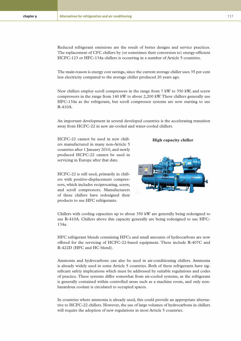
117chapter 9 Alternatives for refrigeration and air conditioning
Reduced refrigerant emissions are the result of better designs and service practices. The replacement of CFC chillers by (or sometimes their conversion to) energy-efficient HCFC-123 or HFC-134a chillers is occurring in a number of Article 5 countries.
The main reason is energy cost savings, since the current average chiller uses 35 per cent less electricity compared to the average chiller produced 20 years ago.
New chillers employ scroll compressors in the range from 7 kW to 350 kW, and screw compressors in the range from 140 kW to about 2,200 kW. These chillers generally use HFC-134a as the refrigerant, but scroll compressor systems are now starting to use R-410A.
An important development in several developed countries is the accelerating transition away from HCFC-22 in new air-cooled and water-cooled chillers.
HCFC-22 cannot be used in new chill-ers manufactured in many non-Article 5 countries after 1 January 2010, and newly produced HCFC-22 cannot be used in servicing in Europe after that date.
HCFC-22 is still used, primarily in chill-ers with positive-displacement compres-sors, which includes reciprocating, screw, and scroll compressors. Manufacturers of these chillers have redesigned their products to use HFC refrigerants.
Chillers with cooling capacities up to about 350 kW are generally being redesigned to use R-410A. Chillers above this capacity generally are being redesigned to use HFC-134a.
HFC refrigerant blends containing HFCs and small amounts of hydrocarbons are now offered for the servicing of HCFC-22-based equipment. These include R-407C and R-422D (HFC and HC blend).
Ammonia and hydrocarbons can also be used in air-conditioning chillers. Ammonia is already widely used in some Article 5 countries. Both of these refrigerants have sig-nificant safety implications which must be addressed by suitable regulations and codes of practice. These systems differ somewhat from air-cooled systems, as the refrigerant is generally contained within controlled areas such as a machine room, and only non-hazardous coolant is circulated to occupied spaces.
In countries where ammonia is already used, this could provide an appropriate alterna-tive to HCFC-22 chillers. However, the use of large volumes of hydrocarbons in chillers will require the adoption of new regulations in most Article 5 countries.
High capacity chiller

118 Preparing for HCFC phase-out: Fundamentals of uses, alternatives, implications and funding for Article 5 countries
Summary of alternatives in new air-conditioning equipment
The current trends indicate that, in the near term, HFC blends are the most likely candidates to replace HCFC-22 in Article 5 countries in larger air-cooled systems.
Air-cooled air-conditioning equipment using HFC refrigerants is already commercially available in most non-Article 5 regions of the world.
Systems using HFC refrigerants are also becoming commercially available in some Article 5 countries, primarily for export.
Hydrocarbon refrigerants may be suitable replacements for HCFC-22 in some catego-ries of products, particularly very low-charge-level applications. There are international and some regional standards that permit the use of hydrocarbon refrigerants at very low charge levels. However, the designer must ensure that local codes or national standards do not pre-empt the international and regional standards.
The role of hydrocarbon refrigerants may ultimately be determined by the costs required to mitigate all safety concerns.
If hydrocarbon systems could be developed as safely as their HFC counterparts, the ultimate decision on their commercial viability would be driven by economic factors, consumer acceptance, and safety codes and standards.
There is a significant amount of research being conducted on R-744 systems. This research is being focused on component development, modelling tools and system designs. However, this research has been primarily related to mobile air-conditioning, refrigeration and water-heating applications. R-744 is used among other things for mobile air conditioners for specific vehicles such as hybrid cars. In Japan, the use of R-744 in heat pumps for water-heater applications is becoming popular due to its high efficiency for this purpose. The development of R-744 air-cooled air-conditioning systems is lagging behind that of HFC technologies by many years.
The manufacturers DuPont and Honeywell have recently developed a near drop-in replacement solution called HFO-1234yf, which enables automobile-makers to meet EU low-GWP requirements. Research and development work is being undertaken in Japan using this compound and a similar compound, HFO-1234ze. However, both of these refrigerants have mild flammability, but they do have very low GWPs (4 and 6). Further research is needed to establish the suitability (technical, price, availability) of these refrigerants in different applications, especially in Article 5 countries.
9.5 Refrigerant options for existing air-conditioning equipment
After the HCFC phase-out occurs in non-Article 5 or Article 5 countries, there will still be a need to service the installed population of products until the end of their useful lives. Servicing of these products can fall into three categories: service field repair, drop-in or retrofill and retrofit.

119chapter 9 Alternatives for refrigeration and air conditioning
All three options will be important for Article 5 countries because systems are often repaired several times in order to extend their useful lives.
In non-Article 5 countries, unit replacement is more common because the costs associ-ated with performing a major repair can often be greater than the cost of replacing the product.
Service field repair is any repair that can follow normal service practices using new, recycled or reclaimed refrigerant.
Drop-in or retrofill replaces the refrigerant without changing the lubricant used in the original equipment.
Refrigerants meeting these requirements are sometimes referred to as service fluids or refrigerants. In cases where the drop-in refrigerant results in a significantly lower capacity or efficiency than HCFC-22, the retrofit approach will be more appropriate.
Retrofit techniques range from simply changing the refrigerant, lubricant and filter dryer (if required) to more extensive modifications, which could include the replacement of the compressor, refrigerant, lubricant, dryer and expansion device, and purging and flushing of the system to remove all residual lubricant from it. Retrofit field repair can be substantially more costly than service or drop-in repairs or even unit replacement.
Drop-in refrigerants
A drop-in refrigerant should require either no system modifications or only minor sys-tem modifications, and as a minimum should result in reliable performance with the existing naphthenic mineral oil or alkyl benzene synthetic oil lubricant used in the origi-nal equipment and should provide substantially the same performance as the original refrigerant.
A number of service refrigerants have been suggested as potential drop-in refrigerants. Until recently, the performance of drop-in applications has not been well documented. However, there are growing numbers of case studies on a number of new refrigerants.
R-424a is a recently registered blend which claims to be a drop-in replacement for HCFC-22. Some case studies have been performed and trials are being carried out.
Comparative data for R-424A
R-424A R-417A R-422D
HFC-134a 47 % HFC-134a 46.6 % HFC-134a 31.5 %
HFC-125 50.5 % HFC-125 50 % HFC-125 65.1 %
isobutane (R-600a)
0.9 % 3.4 % 3.4%
isopentane 0.6 %
n-butane 1 %

120 Preparing for HCFC phase-out: Fundamentals of uses, alternatives, implications and funding for Article 5 countries
Retrofit refrigerants
Refrigerants that require lubricant changes or system component changes are often described as retrofit refrigerants. Retrofit refrigerants will probably not be cost effective if either the compressor or the heat exchangers must be replaced.
R-407C has been demonstrated to be an acceptable retrofit refrigerant for HCFC-22 systems. It has seen widespread use as a retrofit refrigerant in some locations, with some loss in capacity and efficiency. Its performance is very similar to that of HCFC-22, but it does require that the existing naphthenic mineral oil or alkyl benzene synthetic oil lubricant be replaced. R-407C-compatible filter dryers should be installed on HCFC-22 systems retrofitted to R-407C.
The need for, and market impact of, drop-in and retrofit refrigerants will largely be determined by the size of the installed population of HCFC-22 products, the HCFC phase-out schedule, the service tail allowed and the recovery and reclaim practices in place leading up to the phase-out.
The term “service tail” is used to describe the time between the date on which a refriger-ant has been phased out for use in new equipment and the date on which the refrigerant may no longer be produced. It is anticipated that retrofit and drop-in refrigerants will be important for Article 5 countries, because of the limited capital available to manu-facture new non-ODS systems and the longer useful lifetimes which are the result of the common practice of servicing rather than replacing a product when major failures occur.
The installed population of air conditioners and heat pumps has an average service life in non-Article 5 countries of 15 to 20 years. The average life of these products in Article 5 countries may be longer. Therefore, implementing recovery and reclaim programmes coupled with the availability of drop-in and retrofit refrigerants could help reduce the demand for HCFC-22.
Commercialization of suitable retrofit refrigerants should continue because they will provide high value to Article 5 countries.
Hydrocarbons as drop-in refrigerants
It has been reported that HC-290, HC-270 and HC-290/HC-270 blends have been used as drop-in replacements for HCFC-22 in some locations. While these refrigerants may provide capacity and efficiency close to those of HCFC-22, this practice creates a significant safety concern because of the high flammability of these refrigerants.
If hydrocarbons are being considered, all relevant safety standards and codes of practice should be strictly followed. In many cases, the costs of meeting safety standards and codes of practice could be too high to justify a retrofit to a hydrocarbon refrigerant.

121chapter 9 Alternatives for refrigeration and air conditioning
9.6 Refrigerant options for new commercial refrigeration equipment
Commercial refrigeration systems are a broad category of refrigeration systems. The three main subsectors are stand-alone equipment, condensing units and centralized systems for supermarkets.
Commercial refrigeration systems in Arti-cle 5 countries are often products that are locally or regionally made, which are often manufactured in small and medium-sized workshops and factories.
Stand-alone equipment
Stand-alone equipment consists of tightly integrated components. The transition to non-ODS refrigerants in this equipment is complete in developed countries, and use of these systems is also increasing in Article 5 countries.
HFC-134a The dominant alternative refrigerant is HFC-134a in the USA, including for stand-alone display cases, where the refrigerant charge exceeds 0.5 kg.
CO2 Some global companies continue transitioning from high-GWP to low-GWP technologies, such as CO2 and HC-290 (propane).
R-600a (isobutane)
Although there has been some uptake of CO2 in vending machines, this trend does not seem to be growing rapidly due to the relatively high costs of this equipment. The global inventory of vending machines using CO2 in 2007 is estimated at about 90,000. An important advantage of CO2 is its ability to produce both cold and hot temperatures in the same machine using the same thermodynamic circuit.
R-600a (isobutane)
For small commercial freezers, R-600a (isobutane) is the preferred option because of its small charge, high efficiency and low GWP; it is technically and economically viable for about 80 per cent of the vending machine market.
Condensing units
Condensing units are found in many convenience stores and food speciality shops for cooling a small cold room and one or more display cases. The cooling capacity varies from 5 to 20 kW, and most condensing units work at evaporating temperatures that vary between -10 and -15°C. Several small racks of condensing units (up to 20) installed side by side can be found in small machinery rooms in larger food stores.
It is less energy-efficient by far to use several small condensing units than it is to use a well designed small centralized system, but condensing units are chosen for initial or investment-cost reasons and ease of installation, and are available ready to install in large supply companies.
Commercial refrigeration manufacturing

122 Preparing for HCFC phase-out: Fundamentals of uses, alternatives, implications and funding for Article 5 countries
A significant path forward in designing a commercial refrigeration system could be the development of life-cycle cost analysis of the equipment, including energy consumption and maintenance costs.
HFC-134a R-404A R-507A
For new medium- and low-temperature equipment, a preference for the use of HFC-134a is apparent in non-Article 5 Parties, especially in systems with a refrigerant charge larger than 1 kg. R-404A and R-507A are used to replace HCFC-22, especially in low-temperature applications.
HC-290 R-600a HFC-134a R-404A
In some European countries, condensing units using hydrocarbons are sold, but their market share is less than 5 per cent. HCFC-22 is still the most commonly used refrigerant in Article 5 countries, with HFC-134a and R-404A recently introduced in some applications.
R-422D R-422D has been reported as an easy retrofit for HCFC-22 in medium-temperature direct-expansion refrigeration systems, with potential use also for low-tempera-ture systems. A number of case studies report its successful use in commercial supermarket systems and stationary air-conditioning applications, including chilled-water systems. Retrofits of HCFC-22 in medium-temperature equipment using R-422D are being carried out on a large scale in Europe, driven by the pending 2010 phase-out of newly produced HCFC-22 for servicing.
Centralized systems
Centralized systems are similar to condensing units, except that one unit often includes several compressors that serve parallel sets of cooling equipment, and can produce a number of different temperature levels. They tend to be used in supermarkets, in order to lower energy consumption and to increase redundancy. The size of centralized systems can vary from refrigerating capacities of about 20 kW to more than 1 MW.
HFC-134aR-404AR-422D
HCFC-22 is still the most commonly used refrigerant globally. The alternative refrigerants for centralized systems are the same as those for condensing units. However, these systems are more prone to leakage, resulting in high refrigerant emission rates. Significant efforts are being made to alleviate this problem by using indirect or secondary loop systems as well as distributed systems.
HC-290R-600a
In low temperature applications in Europe, the refrigerant CO2 is used in secondary loops as well as in the low-temperature part of cascade systems. In such systems, R-404A, R-717 (ammonia) or HC-290 can be used in the upper cascade. The primary refrigerant is confined in a shorter refrigeration circuit. This not only allows the use of flammable refrigerants, but also reduces the charge of primary refrigerant. In this way, the charge in these systems is reduced by 30 per cent to 40 per cent, which also yields lower refrigerant emissions.
CO2R-404AHybrid
Hybrids between direct and indirect systems are being offered by European installers. CO2 is used as a refrigerant in the low-temperature stage, with an evaporating temperature around -35 °C and a condensing temperature at -12 °C, keeping the tubing and the components under the 2.5 MPa pressure threshold of the current technologies. The condensation of this
CO2 low-temperature stage rejects its heat through the heat-transfer fluid to the medium-temperature stage. So the heat of the CO2 system is delivered at the medium-temperature stage and then released out of doors by the medium-temper-ature vapour compression system. This concept has been employed in very large supermarkets and is claimed to meet the same initial costs as R-404A direct systems because the R-404A charge is reduced from 1.5 tonnes to less than 250 kg. Systems are running with R-404A in large supermarkets using this hybrid technology.

123chapter 9 Alternatives for refrigeration and air conditioning
Retrofit to HFCs increased in the United States during the last quarter of 2007, but still represents a relatively small percentage of the installed base.
HCFC-22 remains the dominant choice in Article 5 Parties for both new equipment and servicing.
In Europe and in Japan, for new equipment, the preferred refrigerants are generally HFCs.
The European F-gas regulation stringently controls refrigerant leakage control, but out-side of northern European countries, emission rates from equipment are estimated to be 15-25 per cent of the total charge per year.
Refrigerant emissions are lowest in supermarkets and highest in hypermarkets.
9.7 Refrigerant options for existing commercial refrigeration equipment
HCFCs have been used both for new equipment and to retrofit CFC-12 equipment. For refrigerating systems which have a long lifetime (up to 15 years and more), inter-mediate HFC-blends such as R-413A have been used for retrofit of CFC-12 medium-temperature systems, and R-417A or R-422B for retrofit of R-502 and even HCFC-22 low-temperature systems.
Stand-alone equipment and condensing units
Three options are available, depending on projected remaining lifetime and costs:
Disposal of the old equipment and purchase of new equipment using a non-ODS •refrigerant;Repair and recharge with the same refrigerant; •Repair and charge with a zero-ODP refrigerant. •
This is covered more detail in chapter 10.
Centralized systems
In developed countries, the equipment is partially or totally renewed every 7 to 10 years, depending on the country. In Article 5 countries, the lifetime is significantly longer, 15 years to 25 years, so the retrofit options have a very significant role in order to avoid the costs of change in the refrigerating system.
It is technically feasible to change from HCFC-22 to a number of established and new HFC refrigerant blends. Initially R-404A or R-407C were developed and have been

124 Preparing for HCFC phase-out: Fundamentals of uses, alternatives, implications and funding for Article 5 countries
used where the cost of retrofit is outweighed by the remaining value of the refrigerat-ing system (the lubricant has to be changed and the refrigerating system has to be flushed).
With this kind of retrofit, associated energy efficiency losses are in the range of 5-10 per cent due to the difference in the thermodynamic properties of the replacement refrigerants compared to HCFC-22.
New HFC blends R-417A and R-422B have been developed to permit retrofit from HCFC-22 to HFCs without change of the lubricant type, but attention must be paid to possible refrigerating capacity losses.
Several new refrigerant blends are entering the market as the phase-out of HCFCs gathers pace. The newly registered refrigerant R-424a, which also claims to be a drop-in replacement, is a different blend similar to R-417A, but with a higher capacity, and which in addition contains a combination of isopentane, butane and isobutene, which provides improved oil return to the compressor while remaining non-flammable as formulated.
Particular issues in Article 5 countries
In many Article 5 countries, even in large supermarkets, plug-in cabinets are preferred to remote cabinets connected to a centralized system. The evident drawback is that plug-in cabinets release all heat inside the sales area and either the air-conditioning system has to be designed to absorb this additional heat or the temperature inside the supermarket can reach very high values (above 30°C and sometimes above 40°C), lead-ing to a poor capability of plug-in cabinets to keep products at the right temperature. Moreover, the overall energy efficiency of supermarkets using plug-in cabinets is low, because the energy efficiency of small compressors is lower than that of medium-sized and large compressors. This situation is also valid for condensing units when those units are replacing larger compressors. Some supermarkets in Article 5 countries use several condensing units in parallel to cool display cabinets, so instead of a rack of three to four compressors, a rack of 20 or more condensing units can be found.
This inefficient solution is chosen for investment-cost reasons and owing to the avail-ability of condensing units everywhere in the world. Moreover, these condensing units are produced in large series in Article 5 countries, avoiding the import of large compres-sors. The energy losses due to the use of condensing units are up to 30 to 50 per cent, compared to the usual efficiency of large compressors.
Retrofit and servicing in Article 5 countries
Retrofit of commercial refrigeration equipment is of particular interest in Article 5 countries in order to save costs. To make possible reliable retrofits, significant training of servicing technicians is necessary. For many servicing companies, the knowledge and equipment are not always available in the countries where they are most needed.

125chapter 9 Alternatives for refrigeration and air conditioning
Retrofits require the change of lubricant and call for more technical precautions. The filter-dryers have to be carefully chosen and, more importantly, the availability of the new polyol ester lubricants as well as the new filter-dryers has to be verified.
In Article 5 countries, many servicing companies still lack adequate tooling: recovery equipment, connecting hoses, recovery cylinders, dry vacuum pumps, and a precise scale. All this equipment is necessary in order to perform proper recovery, evacuation, oil flushing, change of oil, and careful charge of the new refrigerant.
9.8 Refrigerant options for new industrial refrigeration systems
Industrial refrigeration includes process cooling, cold storage and food processing. Both ammonia and HCFC-22 are the dominant refrigerants.
There is increasing pressure on industrial users of HCFC-22 in Europe, but still no universally recognized drop-in alternative for large refrigeration systems with flooded evaporators. Many users are replacing older plants with new systems using ammonia or in some cases ammonia/carbon dioxide cascade systems, but the rate of conversion sug-gests that there will still be a significant number of users with HCFC-22 plants at the beginning of 2010, when a ban on the supply of newly produced HCFC-22 for servicing takes effect.
Growth continues in the use of CO2 in industrial systems across a very wide range of
applications, including plate freezers, blast freezers, cold stores, ice rinks, chill stores, high temperature information technology cooling and heat pumps
Growth also continues in heat-pump applications, in particular in integrated systems that recover heat from refrigeration plants. There is no universally preferred method for this; ammonia systems are the most common, with the number of CO
2 systems now
growing. The uptake of this concept is still restricted by equipment availability, in partic-ular high-pressure ammonia compressors and even higher-pressure CO
2 compressors.
Technical options continue to evolve quickly for low-temperature applications, with CO
2 entering the market as both a heat-transfer fluid and a refrigerant.
CO2 is being used in new small- and large-scale systems with cooling capacities of up to
5 MW in the Untied States, Japan and Europe. Many new CO2 systems continue to be
installed in the Netherlands due to support through financial subsidies.
The use of indirect systems is increasing as a way to reduce the quantities needed for the ammonia refrigerant charge. Research continues in the USA, Japan and Europe on CO
2
as a refrigerant and on CO2 -compatible lubricants. New CO
2 compressor designs were
already introduced in 2004-2006.
Retrofits from HCFC-22 to CO2 or brine systems are being carried out, especially in the
cold-storage sector. The use of equipment with small NH3 charges is steadily increas-ing, and is now expanding into industrial refrigeration systems.

126 Preparing for HCFC phase-out: Fundamentals of uses, alternatives, implications and funding for Article 5 countries
The use of HCFC-22 is either stable or slightly increasing in this sector in Article 5 Parties; however, some interest in non-ODP technologies is now also being reported from Article 5 Parties.
Where new equipment is being constructed, whether for greenfield projects or for the refurbishment of existing buildings, the designer has a wide range of choice of refrig-erant. The decision is usually based on capital cost, but other considerations include operating cost, maintenance cost, the likelihood of refrigerant leakage, health and safety considerations and in specific cases the ease of installation. These issues are explained in each of the following paragraphs.
R-717 (ammonia)
R-717 has been used as a refrigerant for industrial processes since 1872 and is the preferred choice for large installations in most parts of the world. It is acutely toxic in relatively small concentrations, but has a distinctive, pungent odour which is evident at levels well below the dangerous concentration, so the incidence of fatality and serious injury in R-717 systems is extremely low. It is flammable in relatively high concentra-tions, so specific safety measures must be included for industrial systems, but in practice R-717 combustion is not a common concern.
The products of combustion are nitrogen and water, so the chance of safety complica-tions in the event of a major building fire is very low. In the United States and Canada, ammonia has remained the preferred refrigerant for the food and process industries over the last 50 years, and installations are typically large, with R-717 charges ranging from 5 tonnes to 100 tonnes.
The industry in the United States and Canada is well regulated, and although small R-717 releases are frequently reported, the incidence of fatality or serious injury is rela-tively low. For example, the United States Chemical Safety Board (CSB) reports that R-717 incidents account for 11 per cent of all reported chemical releases in the United States, with an average of one every five days, but there were only four fatalities in the ten-year period from 1994 to 2004.
This compares with over 800 deaths from lightning strikes in the United States during the same period. In Europe, R-717 has been widely adopted for industrial refrigeration in the United Kingdom and Germany, but is more tightly regulated in France, Belgium, the Netherlands and Italy, and it is consequently less common.
It is the most common alternative to HFCs for larger systems in Scandinavia, mainly as a result of restrictions and taxation on greenhouse gases. R-717 is less widely used in Article 5 countries, where it was superseded by CFCs from 1970 onwards, and more recently the CFCs have been replaced by HCFCs in smaller systems. It is likely that ammonia will be the preferred replacement for these systems when HCFCs are phased out in these countries, but there will be a need for appropriate legislation and training of contractors and end users to achieve this shift.
In Europe, a blend of R-717 and HE-E170 (dimethyl ether) has been used in some applications to improve the lubricant return in small direct-expansion chillers. It has also been suggested as a refrigerant for high-temperature heat pumps, as it would permit

127chapter 9 Alternatives for refrigeration and air conditioning
slightly higher condensing temperatures to be achieved in current equipment designs. This fluid is sometimes denoted “R-723”, but it has not been submitted for inclusion in ASHRAE 34 or ISO 817. If classified, it would probably be assigned to safety group B3, which would limit its application, and it would not be allocated a refrigerant number in the 700 range.
HFCs
HFCs were introduced as replacements for CFCs in the late 1980s, but they have not been generally accepted for industrial systems. The capital cost of the refrigerant inven-tory and the cost of lubricants are unacceptably high for large industrial systems, and site experience suggests that refrigerant leakage rates from the smaller systems installed with these refrigerants would be unacceptable. An exception is in large centrifugal chillers, where HFC-134a is common, although these units are not usual in industrial systems.
In smaller cold stores and freezers, R-404A and R-507A have been used in commercial-style units, typically with semi-hermetic compressors and condensing units.
Although it has excellent low-temperature properties, R-410A has not been used much in industrial systems, perhaps as a result of the relatively high price of refrigerant.
For an industrial refrigeration system, the cost of the refrigerant charge will be about 5-10 per cent of the total cost of the system. The financial risk associated with the loss of the charge is unacceptably high for contractors and end users.
R-744 (carbon dioxide)
In situations where the use of a direct R-717 system is not possible, or the consequence of leakage is not acceptable, then R-744 has been used in conjunction with the R-717 plant to reduce the R-717 charge and the consequence of leakage. R-744 was first used as a refrigerant in 1867, and it became very popular towards the end of the nine-teenth century, particularly for marine refrigeration, where it was preferred to R-717 on grounds of safety. It fell out of favour in the middle of the twentieth century, when refrigeration systems switched from river water and atmospheric condensers to evapora-tive and air-cooled condensers running at higher discharge pressures. This made R-744 very inefficient relative to R-717.
R-744 found favour again at the end of the twentieth century as an alternative to ammo-nia on safety grounds, and to HFCs on cost and operability grounds. It is particularly well suited to low-temperature freezer systems, where the high operating pressure results in very small compressors and pipe sizes, making equipment economic to install and maintain. The evaporator performance of plate freezers is significantly better with R-744 than with any other refrigerant, making it the preferred solution for plants of that type.
R-744 has also been successfully used in cold stores and chill stores, although the ben-efits are less well defined. In comparison with direct R-717 systems, it has been reported that an R-744 plant is about 5 per cent cheaper to install and has almost exactly the same operating cost. In another study, in comparison with R-717/glycol systems for chill stores, the R-744 option was about 1 per cent cheaper to install than the glycol system, but 15 per cent cheaper to operate.

128 Preparing for HCFC phase-out: Fundamentals of uses, alternatives, implications and funding for Article 5 countries
A comparison is difficult in these cases because it depends on the specification adopted for each system. In the cases mentioned here, the first used electric defrost and hence was cheaper to install but more expensive to operate, and the second used hot-gas defrost, so was more expensive to install but cheaper to operate. If a secondary system is being contemplated on grounds of reduced R-717 charge, then R-744 will offer a cost-effective alternative to glycol.
There are now systems installed with R-744 as refrigerant in niche applications at higher temperatures. One example is the cooling of blade server computers in data centres, where R-744 is a safe alternative to water in high heat-load applications and where air cooling is not sufficient.
Water
Chillers using water compression have been reported occasionally over the last ten years, often in association with industrial projects, as the size of the equipment is a major impediment to its use for building-services applications.
Typical capacities are 1 MW to 6 MW. The industrial projects have been very special-ized and the technology does not seem to be spreading to more general use in the food or process markets.
These systems can be adapted to produce ice slurry as a heat-transfer medium, but they are not capable of running at the lower temperatures required for most industrial applications.
9.9 Options for existing industrial systems
Significant development of replacements for CFC and HCFC refrigerants has been achieved over the last 20 years. In addition to these fluorocarbon replacements, a few cases have been reported where HCFC-22 was replaced by R-717 or R-744, but these projects require a project-specific feasibility assessment of materials compatibility, system-design pressure and equipment suitability, so they are not appropriate in most cases.
For retrofit applications, lubricant compatibility and temperature glide are major con-cerns, and the blends used as substitutes for HCFC-22 in new equipment are not really suitable.
A wide range of blends containing some hydrocarbon, usually propane or butane, are available. The hydrocarbon content is usually restricted to ensure A1 classification, but even a few percentage points can significantly improve the oil management in these systems.
Care must be taken to ensure that operating pressures are compatible with the origi-nal equipment design, and that the plant capacity is not excessively adversely affected. Increased capacity can also be a problem: In some cases, the combination of higher capacity with a lower coefficient of performance can result in significant increases in the current drawn by the compressor motor.

129chapter 9 Alternatives for refrigeration and air conditioning
Most of the retrofit blends for HCFC-22 have a significant temperature glide, and so are not well suited to use in industrial systems using flooded evaporators. This has severely restricted the adoption of retrofit of HCFC-22 in the industrial market, with many end users opting to retain their existing plant for as long as possible and then to replace it with new equipment.
9.10 Transport refrigeration
Transport refrigeration includes transport of chilled or frozen products by reefer ships, refrigerated containers, refrigerated railcars and road transport including trailers, diesel trucks, and small trucks and vans. It also includes the use of refrigeration and air condi-tioning on merchant ships above 300 gross tonnes, and air conditioning in railcars.
This sector is gradually shifting to HFC-134a and R-404A or R-507 and more seldom to R-407C and R-410A. Use of R-410A is expected to increase in the truck and trailer business.
Carbon dioxide is still only used in prototype transport systems. Hydrocarbon refriger-ants might be a future option for trucks and trailers, but they will not be an option for containers because these are often transported below deck.
Ammonia is gaining more popularity on board ships for refrigeration and in a few cases also for air conditioning.
New blends and new refrigerants introduced in prototype systems in car air-conditioning systems have not been explored in the transport refrigeration sector.
Current issues in the transport refrigeration sector are: (1) refrigerant charge reduction, and (2) energy efficiency.
Water-cooled condensers for marine containers are now found on 85 per cent of all containers of the “global market leader”, substantially reducing energy consumption and the space requirement below deck.
HFC-134a generally achieves higher energy efficiency than R-404A in the medium-temperature range, but requires larger compressors and suction lines.
R-410A also achieves better energy efficiency than R-404A, while at the same time reducing the equipment size. The utilization of waste heat in various processes in order to decrease overall carbon dioxide emissions of ships is an upcoming issue.
References
Reference document title Source/Origin
Guidelines for the use of Hydrocarbon Refrigerants in Static Refrigeration and Air-Conditioning Systems, ISBN 1 872719 13 9
Air Conditioning and Refrigeration
Industry Board (ACRIB)

130 Preparing for HCFC phase-out: Fundamentals of uses, alternatives, implications and funding for Article 5 countries
Reference document title Source/Origin
Refrigerating systems and heat pumps – Safety and environmental requirements – Part 4: Operation, maintenance, repair and recovery, ISO TC 86/SC 1 N 176, Date: 2006-04-03, ISO/CD 5149-4, ISO TC 86/SC 1
American National Standards Institute
Global Comparative Analysis of HFC and Alternative Technologies for Refrigeration, Air-Conditioning, Foam, Solvent, Aerosol Propellant, and Fire Protection Applications - Reference 49648
Arthur D. Little, Inc.
Refrigerant Report, 13th Edition - A-501-13 Bitzer International
Carbon Trust Networks Project: Food & Drink Industry Refrigeration Efficiency Initiative Guide 4: R22 phase-out and F-Gas Regulations
Carbon Trust
CTV002, Refrigeration Technology Overview: Introducing Energy-Saving Opportunities for Business
Carbon Trust
Implications of the Acceleration of the HCFC phase-out for China's Refrigeration and Air-Conditioning Industry: Lessons from the US Experience, Mack McFarland, Ph.D.
China Refrigeration and
Air-Conditioning Association Symposium
– Dupont
Refrigeration and Air Conditioning. CFC and HCFC phase-out: Advice on Alternatives and Guidelines for Users
Department for Trade and Industry,
(DTI), UK Government
Improved Energy Efficiency For HFC134a Domestic Refrigerator Retrofitted With Hydrocarbon Mixture (Hc290/Hc600a) as Drop-In Substitute: M. Mohanraj, S. Jayaraj and C. Muraleedharan
Department of Mechanical
Engineering, National Institute of
Technology, Calicut- 673601,
Kerala, India
DuPont DP-1, Global LCCP Assessment: IEA Conference, 23-24 October 2006, Mary Koban, Senior Technical Service Specialist, DuPont Fluoroproducts
DuPont
Containment, Recycling and Retrofitting of HCFCs, John Ellis, F.Inst.R., F.I.Diag.E., LCG
Ellis Training & Consultancy Ltd.
Technical Meeting on HCFC phase-out, 5-6 April 2008, Montreal, Canada, Meeting Minutes
European Commission/ICF
International
Comparative efficiencies and implications for greenhouse gas emissions of chiller refrigerants, James M. Calm
Fourth International Symposium on
Non-CO2 Greenhouse Gases (NCGG-4), Utrecht, The Netherlands,
4-6 July 2005
Refrigeration Drives Sustainable Development: State of the Art - Report Card 2007 – 20th Anniversary of the Montreal Protocol, 10th Anniversary of the Kyoto Protocol
International Institute of
Refrigeration (IIR)
Climate-Friendly Alternative Refrigerant and the Others: New Evaluations for Sustainability, Akira Sekiya
National Institute of Advanced Industrial
Science and Technology, Japan
Energy and Global-Warming Impacts of Not-In-Kind and Next-Generation CFC and HCFC Alternatives, S. K. Fischer, J. J. Tomlinson, P. J. Hughes
Oak Ridge National Laboratory, USA
Options and implications of replacing HCFCs with natural refrigerants in China, Dr. Daniel Colbourne and co-authors: Dr. Volkmar Hasse, Jürgen Usinger, Dr. Thomas Grammig, GTZ Proklima
Symposium on ODS phase-out and
Technology, Development of
HCFCs Substitution, 7–8 December 2007, Beijing

131chapter 9 Alternatives for refrigeration and air conditioning
Reference document title Source/Origin
Air Conditioning and Refrigeration Industry Refrigerant Selection Guide – 2003, Compiled and written by C. A. Lommers, Dip.Mech.Eng., F. AIRAH, M. ASHRAE, ISBN 0-949436-41-0
The Australian Institute of
Refrigeration, Air-Conditioning and Heating, Inc.
(AIRAH)
Technology and Economic Assessment Panel: Response to Decision XVIII/12, Report of the Task Force on HCFC Issues (with Particular Focus on the Impact of the Clean Development Mechanism) and Emissions Reduction Benefits Arising from Earlier HCFC phase-out and other Practical Measures, August 2007
UNEP / TEAP
Report of the Technology and Economic Assessment Panel, May 2008, Volume 1, Progress Report
UNEP / TEAP
2006 Report of the Refrigeration, Air Conditioning and Heat Pumps Technical Options Committee, 2006 Assessment, ISBN: 978-92-807-2822-4
UNEP / TEAP
Aspects of Replacing HCFCs in Refrigeration and Air-Conditioning Products, Lambert Kuijpers, Co-Chair UNEP TEAP
UNIDO, HCFC Alternatives
Seminar, Vienna, 18-20 February
2008
Changing from HCFCs to HFCs, An HVAC Manufacturer's Perspective, Carol Marriott
UNIDO, HCFC Alternatives
Seminar, Vienna, 18-20 February
2008
Cool Technologies: Working Without HCFCs and HFCs, Presentation by Janos Maté, Greenpeace
UNIDO, HCFC Alternatives
Seminar, Vienna, 18-20 February
2008
Approaches to HCFC phase-out in Japan, Ozone Layer Protection Policy Office, METI (Ministry of Economy, Trade and Industry) Sahi Research Center, Shinichiro MIKI
UNIDO, HCFC Alternatives
Seminar, Vienna, 18-20 February
2008
EPA Office of Compliance Sector Notebook, Project Profile of the Rubber and Plastic Industry, 2nd Edition, Chapters I, II and III, February 2005
US Environmental Protection Agency
Refrigerant Blends, Steven R. Szymurski, Director of Research, Air-Conditioning and Refrigeration Institute
World Bank, 9th Annual Financial
Agent Workshop, 1 April 2005
The Impact of the HCFC-22 phase-out on Direct-Expansion Chillers - Periodical
York International


133
10. Good service practice
10.1 Introduction
During the phase-out of HCFC refrigerants, it will be necessary to continue use of exist-ing equipment while reducing the effect of refrigerant emissions into the atmosphere.
Each type of equipment or installation has its own characteristics in terms of refrigerant “consumption”. Fugitive emissions, leak-tightness degradation, ruptures, losses during handling and lack of recovery at the end of life are not the same for each application.
The levels of emission will differ for each system. Some can consume several times their initial charge of refrigerant over their lifetime. Other systems can have near zero leakage.
Often the first step is to reduce leakage of HCFC refrigerants from existing systems, and this can be done by introducing frequent, thorough leak tests using trained personnel and sensitive leak-testing procedures.
Maintaining the system properly is also very important in order to ensure that condens-ing pressures and evaporating pressures are correct for the application and that pipes are properly secured and vibration-free.
The second step is to change the refrigerant in the system to one with a zero ODP. Here there are two options:
Replacing HCFC refrigerant with a “drop-in” replacement while using original •lubricant and components. This is referred to as retrofilling.
Replacing HCFC refrigerant with an HFC refrigerant or an HFC blend, which in •most cases necessitates changing the mineral oil in the system for a polyester or poly-alkaline glycol synthetic oil. This is referred to as retrofitting.
10.2 Assessing options for existing equipment
The first step in assessing how to deal with the existing equipment is to consider its importance and assess any direct dependence on it. For example, if a plant failure could halt production or sales, proper planning of phase-out should be assigned a very high priority and its implementation should be dealt with on a crisis-management basis. On the other hand, if a system consists of a small air-conditioning plant in an office, and the owner feels that he can afford to be without it for a while, a technician or refrigeration engineer can respond on a less urgent basis. It is therefore necessary to determine how crucial the refrigeration or air-conditioning system is to the facility.
Small self-contained systems such as refrigerators, small retail display cases, and small air conditioners are generally very reliable and often run for 20 years or more without major maintenance. In these circumstances, it is appropriate to continue running the

134 Preparing for HCFC phase-out: Fundamentals of uses, alternatives, implications and funding for Article 5 countries
existing plant until it reaches the end of its useful life. The appropriate contingency plans should be made in case the system breaks down and loses its charge of refrigerant, and consideration should be given to the best way of safely disposing of an old system without venting refrigerant into the atmosphere.
More complex items of refrigeration equipment usually require some on-site system assembly and refrigerant filling. Refrigeration systems in this category are susceptible to refrigerant leakage and often require regular maintenance.
Typical examples are cool rooms, freezer rooms, split-system air conditioners, chilled-water systems, and built-up direct expansion plant. There is a range of technical solu-tions that can be applied. In some cases, the best solution is quite clear, but in most instances there are options that require further assessment.
Before assessing the available technical options, it is important to identify the type of equipment and refrigerant that is used in any plant or system, as this will have a direct impact on the choices available.
10.3 Identification of equipment
Refrigerant and lubricant:
Identify the type of refrigerant and lubricant being used.
Compressor type: The type of compressor used in a refrigeration system has a strong bearing on conversion opportunities (e.g., hermetic, semi-hermetic and open-drive compressors have varying opportunities and limitations for conversion).
System operating pressures:
The operating pressures of refrigerants will limit the alternatives and types of replacement refrigerants available for the existing system.
Age of plant: The age and life expectancy of the plant will influence the decision to convert existing equipment or replace it with a new plant.
Compatibility: Various materials used in HCFC refrigeration systems can affect conversion options. When considering conversion to a different refrigerant, establish the type of lubricant, elastomers (rubber/plastic seals, gaskets, etc.) and metals used. New refrigerants must be chemically compatible with all materials used in the existing system.
Cooling capacity: Determine the cooling capacity required for each facility/system and the shortfall/surplus capacity installed on the site. This may affect the technical options to be adopted. System conversions can rectify system shortfalls and/or optimize total energy input by utilizing current techno-logies, design and installation techniques.
10.4 Refrigerant audit
The total quantity of HCFC contained in existing systems and equipment needs to be determined. This will provide important data on the need for replacement and the potential for reusing HCFC from converted or replaced plants and systems.
Many plants suffer from a considerable degree of refrigerant leakage. A low refrigerant consumption may sustain continued usage for a few more years.

135chapter 10 Good service practice
If the equipment is susceptible to leaks, a leakage-reduction campaign should be implemented or the equipment replaced and a new refrigerant used. Purchasing and maintenance records can be consulted to confirm annual consumption.
10.5 Review options
The conservation, retrofilling or retrofitting options available for the air-conditioning and refrigeration industry can be summarized as follows.
Option 1: Continue using existing plant: If a refrigeration system is leak-free, use of the existing refrigerants can continue, provided an emergency plan is established to respond to a plant failure.
Option 2: Reduce leakage: Many refrigeration plants leak. It will prove prohibitive to continue the use of existing plants unless levels of leakage are considerably reduced.
Option 3: Use alternative refrigerants, either retrofilling or retrofitting: The most important factors in selecting a refrigerant to replace an HCFC are low ozone-depletion potential, low global-warming potential, high efficiency and safety of use. It should be noted that all refrigerants must be used with caution. For further information, refer to the manufacturer of the refrigerant.
Refrigerant recovery and reuse: Whenever an old plant is being decommissioned or a plant is being serviced, it is essential that the refrigerant be recovered. During the recov-ery process, it is important that refrigerant be transferred into a cylinder that is empty or that contains the same type of refrigerant. Refrigerant should only be handled by a qualified refrigeration engineer or accredited refrigeration technician.
10.6 Reducing leakage
Importance and sources of leaks
The availability of HCFCs for servicing of existing plants in Article 5 countries will gradually decline over the coming years, as HCFC phase-out activities gather pace.
Equipment owners should ensure that HCFC-based equipment is made leak-free, converted or replaced in an appropriate timescale.
If equipment, such as domestic refrigerators, is normally leak-free, there is no need to convert the system. The equipment can live out its commercial life with the original charge, as there is no requirement to withdraw chlorinated refrigerants from service.
Improving the leak-tightness of a system is a conservation measure that takes into con-sideration the characteristics of components and materials, as well as unpredictable events such as degradation and ruptures.
Emission limitation profoundly affects each process, such as charging or recovery, in which the refrigerant is handled, as well as all procedures performed on systems or parts of systems that contain refrigerants. Emission limitation also requires:

136 Preparing for HCFC phase-out: Fundamentals of uses, alternatives, implications and funding for Article 5 countries
A commitment by management to implement such a policy in designing, operating •or servicing systems;
Design of very tight systems; •
Implementation of metrology for measuring leak flow-rates; •
Implementation of a leak-tightness classification of components such as joints, valves •and flexible hoses;
Enforcement of a “no-venting” handling procedure; •
Availability of adequate high-quality equipment (detectors, area monitors, recovery •units, adaptors, connection hoses, etc);
Use of simple documentation to trace refrigerant movement; •
Definition of refrigerant-saving operation and maintenance procedures; •
Training of technicians in refrigerant leak-tightness control and recovery. •
Emission reduction is not limited to improving leak-tightness or recovering refrigerant. It is an overarching discipline that applies to the entire life-cycle of the product and should be included at the design and installation stages of new products and systems.
Measures for reducing leaks
Refining the designs of all components with a view to contributing to leak-tightness and reducing the refrigerant charge are two key measures that can be introduced. Similarly, assessing and taking actions to limit the incidents that could cause losses through rupture or opening of relief valves is an important design discipline.
The reduction, even elimination, of refrigerant recharge should be the objective of all installations.
Possible measures to reduce refrigerant leakage vary depending on whether installations are fixed or mobile. For fixed installations, key points that result in an improved leak-tight installation are:
Minimization of the refrigerant charge of a system; •
Selection of a refrigerant and design of a system for operation at lower operating •pressures;
Minimization of the number of connections in a system; •
Incorporation of welded joints and fittings instead of screwed joints and fittings; •
Limitation of emission from relief valves; •
Selection of sealed or semi-hermetic equipment in favour of open-drive plant; •
Selection of sealed components less prone to refrigerant leakage; •
Carrying out of extensive pressure testing before evacuation of the system; •
Thorough evacuation of each system using the deep evacuation or triple evacuation •method prior to charging; the lower the vacuum pressure is, the more likely it is that the system will be without leaks;
Use of compatible elastomers and gasket materials; •
Provision of refrigerant detectors in plant areas with early warning alarms. •

137chapter 10 Good service practice
10.7 Retrofilling with a “drop-in”
So-called “drop-ins” are usually zeotropic blends which contain HFC and HC to ensure that the original mineral or alkyl-benzene oil charges into the HCFC system are still miscible and compatible with the drop-in replacement.
Assessment of a suitable replacement refrigerant
Safety All refrigerants used in the air-conditioning and refrigeration industry are potentially dangerous and require different safety procedures and provisions. Ongoing use, design, development, refrigerant properties and tests applied for safety change the requirements and safety provisions for each refrigerant. In some instances, it may be necessary to provide additional refrigerant-detection and oxygen-level-detection systems to ensure that the plant provides a safe operating environment for the operators and occupants.
Compatibility When selecting a replacement refrigerant for an existing system, it is necessary to check the compatibility of the fluid with existing system components and operating conditions, such as operating pressures, lubricants used, motor insulation, component seals and the like.
Availability It is necessary to ensure that the refrigerant selected is commercially available in the short, medium and long terms.
Cost As the cost of refrigerants varies with supply and demand, it is necessary to check the cost of both the first- and the second-choice refrigerants to ensure that future purchases of replacement refrigerants remain affordable.
General retrofill procedure
The general procedure for retrofilling a system with a drop-in is as follows:
1 Ensure that the system is leak-free.
2 Recover HCFC refrigerant into appropriate containers.
3 Record the weight of HCFC recovered.
4 Change the liquid line dryer (if fitted).
5 Evacuate the system to 3-5m bar/2 Torr.
6 Charge the replacement drop-in refrigerant into the system in accordance with the manufacturer’s instructions (i.e., for weight and in liquid phase from the cylinder).
7 Start the system and optimize performance by making adjustments if necessary to expansion valve, high-pressure cut-out, low-pressure cut-out, etc.
8 Thoroughly test the system for leaks.
9 Clearly label the system with the new refrigerant type and remove the old labels to prevent confusion in the future.
Practical tips for retrofilling
1 No drop-in will produce exactly the same results as the original refrigerant.
2 If the latent heat of the drop-in is larger than that of the original refrigerant, it is likely that higher condenser pressures will be present.

138 Preparing for HCFC phase-out: Fundamentals of uses, alternatives, implications and funding for Article 5 countries
3 Note that with conventional, “single-fluid” refrigerants, such as CFC-12, HCFC-22 and others, the pressure is related to the saturated temperature; however, with blended refrigerants, there will be two saturated temperatures for each pressure: the bubble point, and the dew point.
4 The difference between the “bubble” and “dew” points is called the “temperature glide”.
5 The larger the temperature glide, the more likely it is that the refrigerants in the blend will separate (or boil off to vapour at different temperatures) when at equilibrium, i.e., when in a cylinder or in a system that is static during off-cycle.
6 Differential separation and leakage should be taken into consideration when a system leaks vapour while static (off-cycle), particularly if the temperature glide exceeds 1°C. It may be necessary to remove the existing charge and replace it with a fresh charge.
7 All blended refrigerants should be charged so that the refrigerant leaves the cylinder in the liquid phase in order to prevent separation and incorrect charging.
8 All zeotropic blended refrigerants have an R-number in the 400 series, i.e., R-417A, R-413A, etc.
10.8 Retrofitting with an HFC refrigerant
Here it is necessary to remove the mineral oil from the system and replace it with a polyolester, oil lubricant before charging the system with HFC refrigerant because of incompatibility between the HFC refrigerant and mineral oil (HFCs are not soluble in mineral oils).
The general procedure used to retrofit a system from a CFC to an HCF refrigerant is as follows:
1 Ensure that the system is leak-tight.
2 Recover the HCFC refrigerant into a clean cylinder.
3 Drain the mineral oil from the system and replace it with the correct quantity of appro-priate polyolester lubricant.
4 Recharge the system with the previously recovered HCFC refrigerant.
5 Run the system for long enough to “flush” mineral oil residues from the system.
6 Stop the system and recover the HCFC refrigerant again into the clean recovery cylinder.
7 Drain the oil mixture and recharge the system with fresh polyolester lubricant.
8 Recharge the system with the recovered HCFC refrigerant.
9 Run the system for long enough to “flush” mineral oil residues from the system.
10 Stop the system and recover the HCFC refrigerant again into the clean recovery cylinder.
11 Drain the polyolester/mineral oil mixture and test it with an appropriate test kit. The target mineral oil/polyolester lubricant concentration is 5 per cent mineral oil and 95 per cent polyolester lubricant (preferably less than 5 per cent mineral oil).
12 If the mineral oil residue is higher than 5 per cent, then repeat the flushing procedure until it is lower.
13 Once the mineral oil concentration is below 5 per cent, then recharge the system with fresh polyolester lubricant.
14 Now charge the system with HFC refrigerant in accordance with the manufacturer’s instructions.
15 Run the system and make any adjustments as required.
16 Thoroughly test the system for leaks and ensure that all valve caps are in place and tight.

139chapter 10 Good service practice
10.9 Reducing climatic impact
Indirect emissions are the major contributors to a refrigeration system’s global-warming effect caused by its energy consumption. Based on the high percentage of fossil fuels used in power stations, the CO
2 emission could be as high as 0.8 kg per kWh of electri-
cal energy. This results in a significant greenhouse effect over the life of the plant. Small improvements in system efficiencies can significantly reduce the global-warming impact of a refrigerant system over its lifetime.
As well as preventing direct emissions through good containment, good service practice also plays a part in reducing indirect emissions. The following provides an overview of the various proven methods used to reduce the energy consumption of a refrigeration system.
Refrigerant selection
From the viewpoint of economic operation and low energy consumption (i.e. low global-warming impact), it is desirable that a refrigerant have physical and thermal character-istics that will result in a minimum power requirement per unit of refrigerating capacity, that is, a high coefficient of performance. The more important properties of a refrigerant that influence the capacity and efficiency are: (1) the latent heat of vaporization, (2) the specific volume of vapour, (3) the compression ratio, and (4) the specific heat of the refrigerant in both liquid and vapour states. Except in very small systems, a very high latent heat value is desirable in that the mass flow-rate per unit of capacity is less. When a high latent heat value is accompanied by a low specific volume in the vapour state, the efficiency and capacity of the compressor are greatly increased. This not only decreases power consumption, but also reduces the compressor displacement requirements, per-mitting the use of smaller, more compact equipment. However, in small systems, if the latent heat value of the refrigerant is too high, the amount of refrigerant circulated will be insufficient for accurate control of liquid. All other factors being equal, the refriger-ant giving the lowest compression ratio is the most desirable. Low compression ratios result in low power consumption and high volumetric efficiency. This is more important in smaller systems, since it permits the use of small compressors.
Heat exchangers
Heat exchangers such as evaporators and condensers benefit from an improved coef-ficient of conductance, since heat-transfer rates improve, particularly in liquid chill-ing applications. It is also desirable that the pressure—temperature relationship of the refrigerant be such that the pressure in the evaporator is always above atmospheric pres-sure. If the pressure in the low-pressure side is below atmospheric pressure, it is possible for considerable amounts of air and moisture to be drawn into the system in the event of a leak. Reasonably low condensing pressures under normal atmospheric conditions are also desirable, in that they allow the use of reduced wall thickness of materials in construction of the condensing equipment, thereby reducing the size, weight and cost of the equipment.

140 Preparing for HCFC phase-out: Fundamentals of uses, alternatives, implications and funding for Article 5 countries
Evaporating temperature
Compressor performance and cycle efficiency vary considerably with the operating con-ditions of the system. The most important factor governing compressor capacity is the vaporizing temperature of the liquid in the evaporator, that is, the suction or evaporating temperature of the system. The large variations in compressor capacity that accompany changes in the operating suction temperature are primarily a result of change in the density of the suction vapour entering the compressor. The higher the vaporizing pres-sure, the greater is the density of the suction vapour. A given volume of suction vapour handled by the compressor represents a greater mass of refrigerant when the suction pressure is high than when the suction pressure is low. This means that, for any given piston displacement, the mass circulated by the compressor per unit of time increases as the suction pressure increases. A higher suction pressure will result in lower energy consumption of a refrigerating system.
Condensing temperature
The refrigerating capacity of a compressor decreases as the condensing temperature increases. Increasing the condensing temperature while the suction temperature remains constant increases the compression ratio and reduces the volumetric efficiency of the compressor, so that the actual volume of vapour displaced by the compressor per unit of time decreases. Therefore, even if the density of the vapour entering the compressor were to remain the same at all condensing temperatures, the actual mass of refrigerant circulated by the compressor per unit of time would decrease because of the reduction in compressor displacement. Heat rejection dependent on wet-bulb temperature (see: www.engineeringtoolbox.com/dry-wet-bulb-dew-point-air-d_682.html ) can present an advantage over dry-bulb temperature-dependent heat-rejection equipment.
Compressor efficiency
Compressor technology is changing and compressor efficiencies are constantly improv-ing. In addition, there are a number of alternative compressor types available on the market today, all of which have differing performance characteristics and efficiencies. Some of the compressor types available are: (1) reciprocating compressors, (2) rotary compressors, (3) centrifugal compressors, (4) screw compressors, and (5) orbital or scroll compressors. Each compressor type has certain advantages in its own field of use. For the most part, the type of compressor employed in any individual application depends on the size and nature of the installation and on the refrigerant used in the sys-tem. Considerable compressor power can be saved by investigating available alternatives and selecting the most appropriate compressor for the application.
Pipe sizing
In sizing refrigerant pipes, cost considerations favour keeping line sizes as small as pos-sible. However, drops in suction and discharge line pressure cause loss of compressor

141chapter 10 Good service practice
capacity and increase energy consumption. Excessive drops in liquid line pressure cause flashing of the liquid refrigerant, resulting in faulty expansion-valve operation. Refriger-ant lines should be sized for pressure losses of 1kPa or less per segment of the discharge, suction and liquid line piping.
References
Reference document title Source/Origin
Guidelines for the use of Hydrocarbon Refrigerants in Static Refrigeration and Air Conditioning Systems, ISBN 1 872719 13 9
Air Conditioning and Refrigeration
Industry Board (ACRIB)
Refrigerant Report, 13th Edition - A-501-13 Bitzer International
Containment, Recycling and Retrofitting of HCFCs, John Ellis, F.Inst.R., F.I.Diag.E., LCG
Ellis Training & Consultancy, Ltd.
Draft Guidance Note for Ozone-Depleting Substances. Refrigeration, Air Conditioning and Heat Pumps (CFCs and HCFCs), December 2005
Environmental Protection Agency,
Ireland
Air Conditioning and Refrigeration Industry Refrigerant Selection Guide – 2003. Compiled and written by: C. A. Lommers, Dip.Mech.Eng., F. AIRAH, M. ASHRAE, ISBN 0-949436-41-0
The Australian Institute of
Refrigeration, Air conditioning and
Heating, Inc. (AIRAH)


143
11. Foam fundamentals
11.1 Introduction
Foam blowing is one on the main uses of HCFCs globally.
HCFC-141b, HCFC-142b and HCFC-22 are used in the manufacture of several types of polyurethane foams and extruded polystyrene and polyethylene foams.
Polyurethane and polystyrene foams have very good insulation properties and good strength-to-weight ratios and are used in a very wide range of applications. They are very commonly used as thermal insulation for refrigerators, freezers and cold boxes, and in the construction industry as thermal insulation for roofs, walls and storage contain-ers. Flexible polyurethane foams are also used extensively for cushioning in furniture and some types of packaging, and to manufacture a wide range of components for the automotive industry. These are not considered in detail in this document, as they do not use HCFCs.
Increasing oil prices and global efforts to reduce energy consumption and carbon dioxide emissions have led to new regulations and requirements for insulation levels in the construction of new buildings. This has resulted in increased demand for and production of polyurethane and polystyrene foam, as their use is a primary method of improving insulation and reducing energy losses.
Commonly used foamed plastics
Polyurethane Polystyrene (XPS) Polyethylene
Flexible Extruded – Sheet Extruded Sheet
Rigid Extruded – Board Rigid Insulation
Integral-skin
This section of the guide gives some background on the chemical components of poly-urethane, polystyrene and polyethylene, how they are manufactured and what they are used for.
11.2 Polyurethane
Polyurethanes are forms of plastic. They were first developed in late 1930s by the Ger-man chemist, Otto Bayer, and since then they have come to be among the most versatile and widely used plastic polymers. They are used in building insulation, surface coatings, adhesives, solid plastics, and shoes, as well as flexible foams, as mentioned above.
Polyurethanes belong to a larger class of compounds called polymers. They are synthetic (man-made) polymers produced by chemical reactions where single molecules known as monomers are joined together into chains of molecules; chemicals consisting of these chains of molecules are known as polymers.

144 Preparing for HCFC phase-out: Fundamentals of uses, alternatives, implications and funding for Article 5 countries
Polyurethanes can be produced in four different forms, namely, flexible foams, rigid foams, elastomers and coatings. Rigid foams can some times be referred to as cross-linked foams, as the cross linking of the polymer chains causes rigidity.
Categories and uses of polyurethane
Flexible foams Flexible foams are the largest market for polyurethanes. These materials have a high impact strength and are used for making most furniture cushioning. They also provide the material for mattresses and seat cushions in furniture. Semi-flexible polyurethane foams are used to make car dashboard and door liners. Other uses include carpet underlay, packaging, sponges, squeegees and interior padding.
Rigid foams Rigid, or cross-linked, polyurethane foams are used as insulation in refrigerators, freezers and cold boxes and to produce insulation in the form of boards or laminates. Laminates are used extensively in the commercial roofing industry, and buildings are often sprayed with polyurethane foam.
Elastomers Elastomers are materials that can be stretched, but will eventually return to their original shape. They are useful in applications that require strength, flexibility, abrasion-resistance and shock-absorbing qualities. Thermoplastic polyurethane elastomers can be moulded and shaped into different parts. This makes them useful as base materials for automobile parts, ski boots, roller-skate wheels, cable jackets and other mechanical goods. When these elastomers are spun into fibres, they produce a flexible material called spandex. Spandex is used to make sock tops, bras, support hose, swimsuits, and other athletic apparel.
Coatings Polyurethane coatings show a resistance to solvent degradation and have good impact resistance. These coatings are used on surfaces that require abrasion resistance, flexibility, fast curing, adhesion and chemical resistance, such as bowling alleys and dance floors. Water-based polyurethane coatings are used for painting aircraft, automobiles and other industrial equipment.
Integral-skin foams are expanded elastomers.
11.3 How polyurethane is made
The two principal ingredients of poly-urethanes are chemicals known as polyols and isocyanates. Often the term diisocy-anates is used; these are compounds that contain double isocyanate groups.
Polyols and isocyanates are reacted in the presence of suitable catalysts and addi-tives to make different types and grades of polyurethane. Additives are used to protect the physical integrity of the mate-rial, to give it colour and to make it fire resistant.
Isocyanates
The most commonly used isocyanates are products of chemical compounds containing nitrogen, toluene, hydrogen and formaldehyde.
Polyurethane Solid
PolyolIsocyanate
isocyanate + polyol (+ additives) = polyurethane (solid)

145chapter 11 Foam fundamentals
Diphenylmethane diisocyanate (methyl di-p-phenylene isocyanate), commonly referred to as MDI, is the most frequently used isocyanate in the production of rigid and semi-rigid polyurethane foams, and accounts for some 80 per cent of global consumption. Pure MDI occurs as white to pale yellow crystals or flakes with a slightly musty odour. MDI is the least hazardous of the commonly available isocyanates. This reduces its haz-ards during handling compared to the other major isocyanates (TDI, HDI). However, it, like the other isocyanates, is an allergen and sensitizer.
Toluene diisocyanate, commonly referred to as TDI, is used primarily in the manufac-ture of flexible polyurethane foam. TDI occurs as a colourless to pale yellow liquid or crystals with a pungent odour. It turns pale yellow on exposure to air and is soluble in chlorinated hydrocarbons, ether, acetone and esters. It reacts with water, ammonia and alcohols, with the evolution of carbon dioxide and oxidizing agents.
In addition to these isocyanates, more complex compounds are also used such as 1, 5-naphthalene diisocyanate and bitolylene diisocyanate. These more expensive materials can provide higher-melting and harder polyurethanes.
Chemical name Class of isocyanate Common abbreviation
Diphenylmethane diisocyanate
Aromatic MDI
Toluene diisocyanate Aromatic TDI
Hexamethylene diisocyanate Aliphatic HDI
Isophorone diisocyanate Aliphatic IPDI
All isocyanates are toxic and harmful if inhaled, ingested or brought into contact with the skin.
Polyols
The second main component of polyurethanes are alcohol-based compounds known as polyols. They come in different forms for different foam products: elastomers for stretch fibres, and ethers, esters and ureas for foams and coatings.
Polyether polyols are the most commonly used. They are high-molecular-weight poly-mers that have a wide range of viscosity. Various polyether polyols that are used include: polyethylene glycol, polypropylene glycol and polytetramethylene glycol.
Polyester polyols used to be the most commonly used polyols for the production of polyurethanes. However, polyether polyols have become significantly less expensive and have supplanted polyester polyols.
Additives
Some polyurethane materials can be vulnerable to damage from heat, light, atmospheric contaminants and chlorine. For this reason, stabilizers are added to protect them. Anti-oxidants are also used to prevent oxidation reactions.

146 Preparing for HCFC phase-out: Fundamentals of uses, alternatives, implications and funding for Article 5 countries
After the polymers are formed, they are naturally white. Therefore, colourants may be added to change their aesthetic appearance. In these cases, compounds which inhibit discolouration caused by atmospheric pollutants may also be added.
11.4 Polyurethane foam
Polyurethane foam is produced by gen-erating and trapping gas bubbles in the mixture of chemicals as the reaction takes place in order to create a cellular structure in the finished product, which is a foam rather than a solid or dense compound.
The amount and size of these gas bubbles affects the density and physical properties of the foam.
isocyanate + polyol + blowing agent = polyurethane foam
The amount and size of these gas bubbles affects the density and physical properties of the foam.
Foam structure
The gas bubbles created during the reaction that makes the foam can be trapped in the foam. These foams are referred to as closed-cell foams, whilst open-cell foams allow the gas to permeate out of the foam through thinned or broken cell membranes.
Open-cell foams
In general, open-cell foams are soft. The cell walls, or surfaces of the bubbles, are broken, and air fills all of the spaces in the material. This makes the foam softer and weaker than closed-cell foam.
The insulation value of this foam is related to the insulation value of the calm air inside the matrix of broken cells. The densities of open-cell foams are around 8 to 12 kg/m3.
Closed-cell foams
Closed-cell foams are more rigid than open-cell foams. They have varying degrees of hardness, depending on their density. Closed-cell polyurethane foam is normally manu-factured with a density of between 30 and 50 kg/m3. It is often strong enough to walk on without major distortion.
Polyurethane foam
PolyolIsocyanate
isocyanate + polyol blowing agent = polyurethane foam
Blowingagent

147chapter 11 Foam fundamentals
Most of the cells or bubbles in the foam are not broken; they resemble inflated balloons or soccer balls piled together in a compact configuration. This makes the foam strong or rigid because the bubbles are strong enough to withstand a lot of pressure, like the inflated tires that hold up an automobile. The type of gas trapped in the cells also has an effect on the insulation value of the foam, as different gases have different thermal conductivities.
The advantages of the closed-cell foam compared to open-cell foam include its strength, higher insulation value and greater resistance to the leak-age of air or water vapour.
The disadvantage of the closed-cell foam is that it is denser, requiring more material, and therefore, more expensive.
Blowing agentsA blowing agent is any substance which alone or in combination with another substance produces the cellular structure which creates the foam. There are different ways to pro-duce the gas bubbles that create the foaming effect in polyurethane.
Blowing agents are generally classified as physical or chemical. Chemical foaming agents are generally solids and undergo a chemical transformation when producing gas, while physical foaming agents undergo a generally reversible physical change of state, for example vaporization.
Type of blowing agent Examples
Compressed gases that are injected into the pressurized chemical mixture and expand when the pressure is released
Gases such as nitrogen or carbon dioxide under high pressure that are absorbed and finely dispersed into the polymer to be foamed and then expand when returning to atmospheric pressure
Liquids that develop cells when they change to gases
Volatile liquids such as pentane or fluorinated materials that are absorbed and finely dispersed into the polymer to be foamed and then expand when heated to produce a high volume of vapour
Chemical agents that decompose or react under the influence of heat to form a gas
Chemical blowing agents range from simple salts such as ammonium or sodium bicarbo-nate to complex nitrogen-releasing agents.
Traditionally, CFC-11 was the most commonly used blowing agent for polyurethane foam. Since the implementation of the Montreal Protocol and the phase-out of CFC-11, a number of alternatives have been developed. Initial replacements included cyclopen-tane in Europe and HCFC-141b in the Untied States, Asia and the Pacific.
Physical properties of rigid polyurethane foamPolyurethane foam has many applications, but most of them make use of its insulation properties, its high strength-to-weight ratio and its low density.

148 Preparing for HCFC phase-out: Fundamentals of uses, alternatives, implications and funding for Article 5 countries
The exact properties of a foam depend on many variables, including the chemical constituents and their ratio, the additives, the blowing agent and the manufacturing process.
By varying these parameters, very different grades of foam with different physical properties can be produced for specific uses and applications.
The final choice of a foam for a particular application will be based on a combination of the properties that are required for that application. As the chemicals and additives used can be relatively expensive, most manufacturers strive to find the right balance of cost and performance.
For example, rigid polyurethane foam is used to manufacture domestic refrigerators. In this situation, the foam acts not only as the thermal insulation but also as a structural component of the cabinet and doors in combination with the metal casings.
There are several factors that have to be taken into consideration in formulating the insulation foam, including strength, insulation value and density. The combination of these factors determines how much foam is required to provide an efficient level of insulation to the refrigerator, and hence the volume and cost of raw materials. Reducing the thickness of insulation might reduce the cost of the end product, but it would increase the operating cost, as the unit would be less well insulated and so would use more electricity.
In many markets, there are strict regulations governing the levels of efficiency of refrigerators and freezers and the thermal insulation values for buildings.
The main metric units applied to the physical properties of polyurethane foams are:
Property Units
Density Kg/m3
Compressive strength N/m2
Flexural strength N/m2
Tensile strength N/m2
Modulus of elasticity N/m2
Closed-cell content (% )
K-factor (thermal conductivity) W/m² K
Shear strength N/m2
Water absorption (%)
The key properties are insulation and strength. However, density is also crucial, as this affects the cost of the material and also the thickness of the foam needed to achieve the required insulation levels, and therefore the volume of the refrigerator cabinet, since the external dimensions of appliances are fixed by standards.

149chapter 11 Foam fundamentals
General polyurethane manufacturing process
Although there are many variations of foam production equipment, the fundamental process for manufacturing polyurethane foam is similar for all types except spray foam, which is produced on site at the point of application.
The principal method of production involves the storage and preparation of the raw materials (including the blowing agent); metering of the materials including the blow-ing agent to obtain the correct formulation; mixing of the materials and dispensing of the polyurethane mix into some form of mould or onto a conveyor; and finally curing or finishing.
Blowing agent
Polyol
Amine catalyst
Metal catalyst
Isocyanate
Surfactant
FoamMixer
Primary foam components
Raw materials are held in stainless steel tanks, where they are agitated to prevent them from solidifying. Heat exchangers adjust their temperatures to the level that will allow them to react with each other.
A metering device is attached to the tanks so that the appropriate amount of reaction material can be pumped out to be mixed in the correct ratio.
A typical ratio of polyol to isocyanate is 1:2. Since the ratio of the component materials produces polymers with varying characteristics, the metering process must be carefully controlled. On modern equipment, this is done by computerized controllers.

150 Preparing for HCFC phase-out: Fundamentals of uses, alternatives, implications and funding for Article 5 countries
The reacting materials might be passed through heat exchangers in order to maintain the correct reaction temperatures.
The main components are brought together in a mixer or mixing head, where they immediately begin to react to form polyurethane. By the time the liquid mixture is dispensed, the polyurethane is already formed.
The blowing agent can be added at the mixer or mixing head under pressure, or it can be pre-mixed with the polyol. This can be done on site as part of the foam production line or it can be supplied in drums direct from the manufacturer as a pre-blend.
Pre-blends are widely used by systems houses to distribute formulated systems (often polyol and blowing agent). They are very important for small enterprises that do not have the ability to formulate their own polyurethane systems. It is likely that the use of systems houses will play a key part in phasing out HCFCs in Article 5 countries. One of the main barriers to adopting hydrocarbon solutions for foam blowing has been the safety issues relating to the transport of pre-blends containing hydrocarbons.
The industry is still divided on whether this transport can take place safely and, if so, under what conditions. A limited number of projects are seeking to address these uncertainties.
Isocyanate is mixed with polyol and the blowing agent in the mixing head. This can be done mechanically using an electrically driven mixing device (low-pressure foam-ing machine) or in counter-flow under high pressure (high-pressure foaming machine). Then the foam is dispensed through the mixing head and the blowing agent expands, causing the foaming process.
Polyol Blowing agent
Mixed polyol & blowingagent
Isocyanate
Mixinghead
Polyurethane foam
Storing and mixing foam components

151chapter 11 Foam fundamentals
The curing or finishing process is the final stage of the manufacturing process, when the foam stabilizes and after which no further chemical reaction takes place.
This process can be accelerated by heating, which is commonly used in moulded products to improve production capacity by reducing mould time.
A typical foam manufacturing line is often described in two main sections, the “wet part” and the “dry part”.
The wet part includes the chemical storage tanks, and metering, mixing and dispensing equipment, while the dry part includes all the subsequent equipment used to process the foam after it is dispensed. This includes moulds, conveyor systems, curing ovens, etc.
From the mixing head, the foam is processed in different ways to form different products. The most common products and manufacturing processes are described below.
11.5 Rigid polyurethane foam
Slabstock
The term slabstock is used to describe large blocks of material that are used as a basic material for a variety of applications.
Rigid foam slabstock can be cut and fab-ricated into a variety of product shapes and forms; it is commonly used for insu-lating pipes and storage tanks, as insula-tion boards in building construction and for refrigerated transport containers.
Production process
Rigid slabstock is produced using either a discontinuous or a continuous manufacturing process.
In the discontinuous method (block foam), the chemical components of a slow-reacting foam system are weighed, and hand- or machine-mixed then poured into a wooden or cardboard mould. The mould is then fitted with a floating lid which rises on top of the expanding foam, keeping the top surface of the foam block level and flat.
The production rate of the discontinuous method can be increased by replacing the hand-mixing process with mechanical stirrers or by foaming machines that both mix and dispense the foam reaction mixture into the mould.
Slabstock production

152 Preparing for HCFC phase-out: Fundamentals of uses, alternatives, implications and funding for Article 5 countries
In both processes, the foam rises owing to the expansion of the blowing agent and cures. Then it is cut into sections for use in the applications and products listed above. In general, rigid slabstock has neither a facer nor an impermeable liner attached to it.
Domestic refrigerator and freezer insulation
Rigid polyurethane foam is the most common insulation used in refrigerators and freezers. In these products, the foam serves not only as a key element in the structure of the appliance, but also as a very effective insulation.
Although the basic requirements for refrigerator/freezer foam insulation are similar for most manufacturers, differing manufacturing facilities, market condi-tions and local regulatory requirements have resulted in significant variations in formulations and foam thickness being used in domestic appliances. The grow-ing importance of energy consumption in many markets has been a major factor in this.
In the continuous process, as shown below, the foam reaction mixture is dispensed continuously into a trough on a moving conveyor belt lined with paper or polyethylene film. The foam expands as it moves on the conveyor belt. Conveyor systems can be fitted with equipment to keep the top surface of the foam flat and level in the same way as the floating lid does in the discontinuous process.
Paper
Conveyor moves at 2-3 metres per minutecream time
rise time
gel time
full risefoam cuttingtack free
Mixing and dispensing
creaming
mixinghead
rising curinggelling blockfoam
Storing and mixing foam components
Refrigerator foaming machine

153chapter 11 Foam fundamentals
Production process
The liquid polyurethane mixture is injected between the outer shell and the interior liner of an appliance cabinet, where they react, flow and expand to form rigid polyurethane foam throughout the cavity.
Substantial fixtures are provided to support the walls, which are under pressure from the foam. This is closed-cell foam, and the blowing agent is trapped inside the foam. Typically, less than 5 per cent of the blowing agent escapes during the foaming process.
In very small-scale production facilities in Article 5 countries, it was not uncommon for foam components to be mixed by hand and poured into the moulds using buckets. Currently, low- or high-pressure foaming machines are used. High-pressure machines ensure better homogeneity of the mix, higher productivity, a cleaner production process and versatility regarding the foaming agents used.
Traditionally, this type of foam was manufactured using CFC-11, which provided excel-lent all-round properties. The main consideration in replacing CFCs was to maintain the properties of the foam.
Other non-building-related insulation applications
Rigid polyurethane foam is used as insulation in a variety of other applications:
Water heaters Foam insulation ensures a significant saving in energy consumption, particularly in designs where the space for insulation is limited.
Commercial refrigera-tors and freezers
Typically much larger than domestic units, and include open top and vertical reach in display units.
Picnic boxes (coolers) With a premium on insulation value and strong lightweight structures.
Flasks and thermoware Several types of articles require the same characteristics as picnic boxes.
Refrigerated containers (reefers)/transport
A very stringent application, with emphasis on durability and minimum wall thickness whilst maintaining insulation value.
Production process
Products for all the applications listed above are produced by direct pour or injection of the foam chemicals between the inner and outer surfaces of the article. Most are held in moulds or jigs during the foaming process. Refrigerated containers are also produced by foaming section by section into a large pre-assembled jigged structure.
Boardstock
Rigid polyurethane can be laminated in a continuous process with a variety of facing materials such as aluminium foil, paper, glass roofing felts, and plasterboard to make insulating panels used in the construction industry, as well as for other commercial and industrial insulation applications.

154 Preparing for HCFC phase-out: Fundamentals of uses, alternatives, implications and funding for Article 5 countries
Boardstock is used in building construction as roof insulation, and in walls, cavities, internal linings, exterior facades and sheathing for residential construction. As they have a low thermal conductivity and therefore improve energy efficiency, boardstocks containing fire retardant have good safety credentials and are strong and easy to use.
Production process
There are two main types of continuous laminating machines. The continuous horizontal laminator is the standard type of laminator and is used to produce products with two flexible facers, e.g., aluminum foil, paper or roofing felt or one flexible facer and one rigid facer. The second main type of machine is the inverse laminator, which produces boardstock with a single rigid facing in sheet form.
The chemical components are metered and mixed from the mixing head onto a pressure conveyor, where external heat may be applied to promote faster curing before the foam is moved to the cut-off saw area. This product can also be produced using slabstock production methods.
Sandwich panels
Sandwich panels with thicknesses of from 30 to 200 mm are made with rigid foam cores between two rigid facings, which are often profiled to increase the rigidity of the panels. The facing materials are typically steel, aluminium or glass-fibre-reinforced plastic sheet.
Sandwich panels are used in the construction industry for fabricating cold stores for frozen and fresh food storage and cold rooms in retail stores. They are also useful in the construction of sealed or controlled rooms in food processing or pharmaceutical factories and laboratories and to make insulated trucks and reefer containers.
Production processes
Sandwich panels can be made by either a continuous or a discontinuous proc-ess.The continuous process uses a hori-zontal laminator similar to that used for the production of boardstock. However, additional equipment is installed to con-vert coiled sheet steel into profiled fac-ings which are fed into the laminator. In the discontinuous process, pre-profiled or flat facings are assembled, with appropri-ate spacers, in single- or multi-daylight or in oyster presses. The foam is injected at multiple ports or a lance withdrawal technique is used.
Boardstock production
Sandwich panel production

155chapter 11 Foam fundamentals
Spray foam
Spray foam is used to provide rigid ther-mal insulation to existing uninsulated structures and components. It is com-monly used to insulate roofs as well as commercial buildings, industrial storage tanks, piping and ductwork, and refriger-ated transport trailers and tanks. Spray foam is applied by contractors in the field in accordance with the instructions of manufacturers of spray foam systems.
Production process
Spray foam is applied using a hand-held spray gun, in which pressurized polyol and iso-cyanate liquids and the blowing agent are metered, mixed and dispensed directly onto the substrate being insulated. The ratio of foam-component raw materials is varied to suit the specific application. For example, roof insulation might require higher compres-sive strength than wall cavity insulation, where the foam needs to be highly reactive to help it stick to vertical surfaces during application.
This method of application facilitates coverage of large and complex surfaces. When a thick layer of foam is needed, multiple thin layers of foam, of not less than 10 mm, are applied to create the thick layer.
Pipes can also be insulated with spray foam by using a fixed spray gun and rotating and traversing the pipe.
Pipe-in-pipe or preformed pipe
Foam-insulated pipe-in-pipe sections are steel pipes encased in rigid insula-tion foam with a plastic outer protective coating. They are used to transport hot or chilled fluids either underground on pipe supports, or in situations where heat loss or gain in the fluid is to be avoided, for example, in district heating systems where hot water is pumped significant distances from the boiler or heat source to numerous buildings and residences, or in factories where chilled water for proc-ess cooling is circulated to heat exchang-ers located remotely from the refrigera-tion system. The foam density used in these applications is high, typically in the range of 70-80 kg/m3, to meet requirements in respect of strength and durability.
Application of spray foam
Pipe insulation

156 Preparing for HCFC phase-out: Fundamentals of uses, alternatives, implications and funding for Article 5 countries
Production processes
Pipe-in-pipe sections are produced by injecting the foam chemicals into the cavity between the inner and outer pipes. Preformed pipes are produced by pouring or inject-ing the foam chemicals into half-section moulds. Continuous processes have been intro-duced in which the foam is injected onto the inner pipe, cured and the outer plastic cover is then extruded onto the foam through an annular die.
Single/one-component polyurethane foam (OCF)
Single- or one-component foams are used by both the building industry and the do-it- yourself market in a variety of applications. These include draft-proofing around pipes, cable runs, doors and windows; sealing doors and window frames; and joining insulat-ing panels, roofing boards and pipe insulation. Single-component foams are preferred because they are portable and easy to apply, and offer both thermal and sound- insulation properties.
Production process
Single component foams are supplied in pressurized cylinders and aerosol cans fitted with a nozzle through which a thin strip of material is extruded. After application, the foam expands at room temperature and cures by reacting with moisture in the air. This characteristic is unique to one-component foams. The foam continues to cure internally after becoming dry to the touch as moisture from the air diffuses into the foam. The total time needed for foam cure depends on the temperature and relative humidity.
Other rigid foams
Rigid polyurethane foam is also used in a number of non-insulation applications, includ-ing low-density packaging foam, flotation devices, florist’s foam and energy-absorbing foams for side impact in automobiles.
Non-insulation rigid foams are manufactured using various processes, including spray, moulding or rigid slabstock, using conventional or high-pressure polyurethane dispensing equipment.
Most integral-skin and miscellaneous foams have an open-cell structure, where the blowing agents used in manufacture are emitted to the atmosphere during the foaming reaction or soon thereafter. Rigid integral-skin and flotation foams have a closed cell structure, but low thermal conductivity is not important in these products.
Moulded/integral-skin foams
Moulded foams are mainly used in transportation applications, such as seat cushions, back cushions, armrests and headrests, and a variety of specialist applications. They are also used for sound-dampening in cars, back-foaming of carpets and firewalls.

157chapter 11 Foam fundamentals
Production process
Product moulds of the required shape and size are cleaned then coated with a release agent to allow the moulded foam to be removed easily from the mould at the end of the process. Pre-blended foam is then dispensed through a mixing head into the open moulds, either manually or automatically. The moulds are then closed and the foam reaction is allowed to take its course. As the foam expands, it fills the mould cavity.
The moulds are opened after a specified time and the products are removed. It is com-mon for the products to be manually flexed and or crushed by rollers upon removal from the mould. This helps open any cells within the structure which might have remained closed. In some cases, the product is heat-treated to further cure and harden the skin.
Integral-skin foams have a low density, a softer core surrounded by high density and a nearly solid skin of the same material. In the case of rigid integral-skin foam, the skin-core structure results in good flexural properties at low overall densities, and conse-quently such foams find wide application as structural materials. For example, integral skin foams are used as structural elements in furniture, and for making instrument housings and automobile dashboards where good surface finish, low thermal conductiv-ity and ease of processing make them a suitable and economical material. Integral-skin foams are also used as shoe soles and other bespoke products.
Integral-skin foams are moulded foams, manufactured either by injection into closed vented moulds (i.e., steering wheels) or by pouring into open moulds, as in the case of shoe soles. The increased density of the outer skin occurs as a result of the blowing agent condensing at the mould surface, compressing the cells of the foam in that area, and of over-packing of the mould, which forces a concentration of foam.
HCFCs are very rarely used in this sector.
11.6 Polystyrene
Background
Polystyrene is a relatively inexpensive and hard plastic. It is used abundantly in the manufacture of everyday products, from television-set housings to clear plas-tic drinking cups and control knobs for radios.
However, polystyrene is best known for its foamed versions, which are used to make coffee cups, food cartons, and packaging and thermal insulations products. There are three types of foamed polystyrene:
Polystyrene cup

158 Preparing for HCFC phase-out: Fundamentals of uses, alternatives, implications and funding for Article 5 countries
Extruded polystyrene board (XPS board) •Extruded polystyrene sheet (XPS sheet) •Expanded polystyrene (EPS) •
In the early days of the Montreal Protocol, global media attention was focused on every-day polystyrene foam products (produced from XPS sheet), as they were commonplace, visible and recognizable to most ordinary people. The pressure to phase out CFCs in these particular areas was therefore driven in many cases by consumer pressure. Suppli-ers of raw materials developed new formulations, and CFC-free polystyrene products quickly became available, whilst unseen or less well known uses of CFCs continued.
The consumption of foamed polystyrene products has in general decreased in many regions since fire performance and environmental issues were originally brought to light, particularly in North America and Europe.
How polystyrene is made
Raw styrene is extracted from petroleum or natural gas. Like urethane, styrene is a monomer which can be polymerized into chain molecules known as polystyrene. In contrast to polyurethane, it is a thermo-plastic polymer rather than a thermoset polymer. It is supplied as a raw material to foam manufacturers in the form of small white spherical beads with a typical diameter of 0.5 mm to 1.5 mm.
Expanded polystyrene foam (EPS)
Expanded polystyrene foam (EPS) is made up of individual cells of low- density polystyrene; EPS is extraordinar-ily light and can support many times its own weight in water. Because its cells are not interconnected, heat cannot travel through EPS easily, so it is a good insula-tor (although not as good as some types of polyurethane). EPS is used in flotation devices, insulation, egg cartons, packag-ing for meat and produce, sandwich and hamburger boxes, coffee cups, plates, picnic coolers and many other similar applications.
Unexpanded polystrene beads
Expanded polystrene packaging

159chapter 11 Foam fundamentals
Production process
First the beads are pre-expanded using either steam (the most common method) or hot air (for high-density foam, such as that used for coffee cups); the heating process is carried out in a vessel hold-ing anywhere from 150 to 2,000 litres of beads. When the beads are heated, the expanding agent starts to boil, the polymer softens and the beads expand to about forty times their initial size.
During pre-expansion, an agitator is used to keep the beads from fusing together. Since expanded beads are lighter than unexpanded beads, they are forced to the top of the vessel’s cavity and discharged. This process lowers the density of the beads to 3 per cent of their original value and yields a smooth-skinned, closed-cell EPS that is excellent for detailed moulding.
The pre-expanded beads are usually allowed to age for at least 24 hours in mesh storage silos. This allows air to dif-fuse into the beads, cooling them and making them harder.
The matured beads, which now have a closed cellular foam structure, are placed in a mould and again reheated with steam. The pre-expanded beads expand further and completely fill the mould cavity and fuse together.
When moulded, nearly all the volume of the EPS foam (in fact 98 per cent) is air. This is what makes EPS so lightweight and buoyant.
HCFCs are not used in the production of expanded polystyrene.
11.7 Extruded expanded polystyrene foam (XPS)
Extruded polystyrene differs from expanded polystyrene in that the blowing agent is added during the process rather than being contained in the polystyrene beads.
Many extruded polystyrene foam sheet conversion projects were supported by the Mul-tilateral Fund in order to phase out mainly CFC-12 by conversion to the use of hydro-carbons, particularly butane and LPG, for polystyrene sheet production. The use of HCFC-22 and HCFC-142b in the production of polystyrene insulation board is still widespread and has been growing in some Article 5 countries.
Expanded polystrene moulding machine
Pre-expansion of styrene beads

160 Preparing for HCFC phase-out: Fundamentals of uses, alternatives, implications and funding for Article 5 countries
Extruded polystyrene sheet
Extruded polystyrene foam sheet is used primarily to manufacture food-service and food-packaging products, such as hinged carry-out containers, single-service plates, cups, egg cartons and food trays. It is also used to make loose-fill packaging material known as dunnage and laminated sheets used as art board and as insulated packaging.
Production process
Extruded polystyrene foam sheet is produced by a process that mixes polystyrene resin with additives and melts the mixture to a low viscosity. This is done in a machine known as a two-stage screw extruder. Blowing agents are injected into the extruder under high pressure and dispersed into the polymer melt. The molten polystyrene is then extruded into the proper shape at high temperature and pressure.
As the molten polymer leaves the die, the dissolved blowing agent vaporizes and expands. This reaction causes the plastic to foam. An annular die is used to form a tube, which is subsequently slit to make foam sheets. Extruded foam sheet is nor-mally aged for two to four days prior to being formed, cut or wound into rolls.
Forming is done by applying a combination of pressure and heat known as thermofor-ming. The majority of extruded polystyrene foam sheet produced globally is made into thermoformed products.
The thermoforming step typically generates a substantial amount of foam scrap. In some cases, 30 per cent to 40 per cent of the extruder feed becomes scrap.
Manufacturing processes commonly include grinding and reprocessing steps after final cutting and thermoforming. The reprocessed pellets of recovered foam scrap are recy-cled back to the extruder feed. The typical extruder feed mixture is 65 per cent virgin polystyrene and 35 per cent recycled polystyrene.
Extruded polystyrene insulation board
Extruded polystyrene insulation board is rigid foam with a fine closed-cell struc-ture. It consists almost entirely of polymer and blowing agent, hence its low density. Globally, approximately 90 per cent of extruded polystyrene rigid foam boards are used for thermal insulation purposes.
Polystrene extrusion machine
Extruded polystrene insulation

161chapter 11 Foam fundamentals
The type of blowing agent used determines the character of the cellular structure formed during the manufacturing process. There are two main types of foam boards: boards with a smooth skin covering and boards with a planed or cut cell surface that provides grip for plaster, adhesive and concrete.
Self-skinned boards are used as insulation for roofs, floors and walls in buildings; they are also used as frost protection under roads, airport runways and railways in colder countries.
Planed or cut surface boards are used as insulation in concrete buildings, for backing plaster and tiles and as core material for sandwich panels. They are also used in the construction of cold stores, as well as in a variety of specialty applications. Their high moisture resistance also makes them suitable for use in humid places.
Extruded polystyrene insulation boards are economical and practical for below-ground building applications, such as basements, foundations and earth-sheltered homes, and inverted roof applications, where the waterproofing membrane is below the insulation material.
Production process
Extruded polystyrene foam board is manufactured using an extrusion process similar to that used for polystyrene sheet. Polystyrene resin is mixed with addi-tives and fed into an extruder, where it is melted.
Blowing agent is injected under high pres-sure and becomes dispersed throughout the molten resin. This produces a gelati-nous substance that is cooled and then extruded through a die with a rectangular cross section. As the gel leaves the extru-sion die, the blowing agent vaporizes and expands, creating a closed-cell foam structure within the polystyrene.
When the foam has been formed, it is transported away by a continuous conveyor belt and cut into appropriate lengths and widths. This cutting section can also include equipment to remove the skin in order to make planed boards.
Scrap material generated from the production process can be recycled, but this involves grinding the material down and results in the loss of the blowing agent. In closed-cell insulation foams, such as extruded polystyrene, the blowing agent performs two functions: It drives the foaming process and it provides thermal insulation.
A blowing agent which stays in the foam to provide insulation value is known as the pri-mary blowing agent. It is sometimes referred to as the insulating gas. A second blowing agent is sometimes used to support or improve the foaming process; this is known as an auxiliary blowing agent.
Polystrene board extrusion

162 Preparing for HCFC phase-out: Fundamentals of uses, alternatives, implications and funding for Article 5 countries
It is possible to improve the foaming process using vacuum foaming technology. However, a primary blowing agent is still required to provide insulation performance.
11.8 Polyolefin foams
Another, less common, category of plastic foam is polyolefin foams. Olefins are hydro-carbon compounds produced from petroleum and include butene, ethylene and propylene.
Polyolefins are polymers of olefin compounds, including polyethylene and polypro-pylene resins. Additives such as ethylene or vinyl acetate or ethylene or acrylic acid copolymer resins are added to modify the properties of the foam.
Several different manufacturing processes are used for polyolefin foams, resulting in different types of foam. Decomposable blowing agents such as azodicarbonamide can be used, but the resulting products have different properties and are typically more expensive than polyolefin foams manufactured with physical blowing agents.
Products manufactured using decomposable blowing agents are not generally considered to be substitutes for non-cross-linked polyolefin foams.
In most polyolefin foam applications, products are used because of specific properties. The most important of these properties is the material’s ability to provide insulation from mechanical vibration and thermal stress caused by significant variations in product temperature.
Moulded foams
Polyethylene and, more recently, polypropylene resins are used in expandable bead products, which may be subsequently shape-moulded.
These foam products are used primarily as moulded cushion packaging and automotive bumper systems. CFC-11 was previously used as a blowing agent.
All bead producers now use hydrocarbons or carbon dioxide. Consequently, no further comments will be made regarding these products.
Sheet products
Both polyethylene and polypropylene resins are extruded into sheet products.
These sheet products are commonly used as protective packaging for furni-ture, electronic devices and other goods.
Polyethylene sheet for packaging

163chapter 11 Foam fundamentals
Other applications include flotation devices such as life vests, construction materials and gaskets.
CFC-11, CFC-12 and CFC-114 have historically been used as blowing agents for most sheet products.
Plank products
Polyethylene resins are used in the manufacture of extruded plank products. Their most frequent application is designed cushion packaging for electronic or other high-value goods. Some plank products are also used in military packaging, flotation, construction, aircraft seating and other applications.
CFC-12 and CFC-114 were generally used in the manufacture of plank products.
Tubular products
Polyolefin foam can also be extruded in an annular shape, i.e., as a tube, for use as thermal insulation for pipes. Applications include residential hot- and cold-water pipe insulation and similar near-ambient-temperature applications.
Historically, either CFC-12 or CFC-114 was used as blowing agent.
Production processes
In the case of extruded products, the resin is melted and mixed with the blow-ing agent(s). The resin and blowing agent are then passed through a die, where the product rapidly expands and cools.
For sheet products, a circular, annular die is used to form a thin-walled hol-low cylinder of foam. This foam tube is subsequently slit to produce a flat sheet that can then be rolled for storage or shipment. Sheet products are normally no thicker than 6 mm, and most are no thicker than 3 mm.
Typically, plank products are made using a specific die, which produces the particular cross-section desired. Each cross-section requires a different die. The plank is then cut to length and, if necessary, the edges are trimmed. Plank products can be from 12 to over 100 mm thick, are made up to 1,200 mm wide, and are occasionally made in cir-cular or other non-rectangular cross-sections. One process injects the foaming materials into a closed cavity to enhance the dimensional stability of the product.
Polyethylene sheet extrusion

164 Preparing for HCFC phase-out: Fundamentals of uses, alternatives, implications and funding for Article 5 countries
Tubular pipe insulation also uses an annular die, but one producing a reasonably small-diameter, relatively thick-walled foam product. The inside diameter of the tubing ranges from 6 mm to 125 mm, with wall thicknesses of 5 to 50 mm.
All three foam types are closed-cell products. Thus, most of their blowing agents are initially trapped within the foam. With very thin-sheet products, a significant portion of the blowing agent may be lost at or near the die. For extruded plank, tubing and thicker sheet products, very little is lost at the die, although some will be lost in trimming operations, which open the cells.
References
Reference document title Source/Origin
BASF Corporation, Polyurethane MDI Handbook BASF Corporation
The production of rigid polyurethane foam, Dr. Manfred Kapps and Siegfried Buschkamp
Bayer
A Comparison of CO2-equivalent Emissions from the Use of Various Extruded Polystyrene Foam Insulations: XPS foam sheathing applied to exterior walls of single family residential housing in four cities in the United States, by Nadine Rauscher
Dow Chemical Company
An Evaluation of the Thermal Conductivity of Extruded Polystyrene Foam Blown with HFC-134a or HCFC-142b, Chau V. Vo
Dow Chemical Company, 1605
Joseph Drive-200 Larkin Center,
Midland, MI 48674
ecomate® Foam Blowing Agent. Paper by John Murphy, Mark Schulte, Buck Green
Foam Supplies, Inc.
Rigid Polystyrene Foams and Alternative Blowing Agents, Kyung Won Suh and Andrew N. Paquet, The Dow Chemical Company, Midland, MI, USA, ISBN: 0-471-49752-5
Modern Styrenic Polymers:
Polystyrenes and Styrenic Copolymers
Technical and Environmental Acceptance of HFCs as Blowing Agents for XPS Boards, Christer Bratt and Arnaud Albouy
Nordic Foam, Sweden
Energy and Global Warming Impacts of Not-In-Kind and Next Generation CFC and HCFC Alternatives; S. K. Fischer, J. J. Tomlinson, P. J. Hughes
Oak Ridge National Laboratory, USA
HFC Blowing Agents for Rigid Insulation Foams, Lothar Zipfel and Christoph Meurer
Solvay Fluor
HFC Blends for the Production of High Performance XPS Insulating Foams, Pierre Dournel and Lothar Zipfel
Solvay Research & Technology, Solvay Fluor und Deriviate
GmbH
2006 Report of the Rigid and Flexible Foams Technical Options Committee, 2006 Assessment, ISBN: 978-92-807-2826-2
UNEP / TEAP
Report of the Technology and Economic Assessment Panel, May 2008, Volume 1, Progress Report
UNEP / TEAP
EPA Office of Compliance, Sector Notebook Project, Profile of the Rubber and Plastic Industry, 2nd Edition, Chapters I, II and III, February 2005
US EPA

165
12. Alternative blowing agents for foam production
12.1 Introduction
Decision XIX/6 will require the phase-out of HCFC-141b, HCFC-142b and HCFC-22 in the production of polyurethane, polystyrene and polyolefin foams. Whilst consider-able experience has already been gained in non-Article 5 countries in the phase-out of these HCFCs, information on it has not yet been sufficiently disseminated to assist decision-making in most Article 5 countries. This section gives a brief overview of the current and emerging options for the replacement of HCFC blowing agents.
Although blowing agents can be recovered efficiently from appliances, the effectiveness of regulation varies substantially by region. Significant additional work has been con-ducted on evaluating the practicality of blowing-agent recovery from building foams. Cost effectiveness depends substantially on underlying waste policy and, in particular, segregation of demolition waste. The potential of carbon finance to assist in the bank management process is under serious evaluation.
12.2 Rigid polyurethane foam
Boardstock
HCFC-141b is widely used (HCFC-141b/HCFC-22 blend is also used), as it provides the best insulation value of the CFC-11 replacements, and boards made in this way satisfy a wide range of building codes.
N-pentane, isopentane and cyclopentane and hydrocarbon blends are used in markets which already require a zero-ODP option. However use of n-pentane and isopentane require significant changes in the processing area of the factory to ensure safe opera-tion because of their flammability. In addition, there are issues of dimensional stability, thermal conductivity and formulation to satisfy fire codes.
There have been dimensional stability problems in the European market, with shrink-age of installed roof boards, particularly in winter conditions. This has arisen because of the high boiling point (36°C) of the n-pentane and is similar, in some respects, to the problems seen with HCFC-141b.
Industry has addressed the issue by assuring that the foam density is maintained and through the introduction of new test methods.
The need to meet fire codes means that the potential economic advantage of using a cheap blowing agent is not realized in practice. The inherent flammability of the blowing agent is counteracted, in practice, by the use of flame retardants. Preferably, these should be of the reactive type, because non-reactive fire retardants can lead to plasticization of the foam matrix.

166 Preparing for HCFC phase-out: Fundamentals of uses, alternatives, implications and funding for Article 5 countries
By these means, most small-scale tests can be passed, as can some of the larger-scale tests. However, the increasing stringency of both the EU harmonized tests that are being developed and the insurance companies’ tests results in pentane-based boards being unable to meet all market requirements.
For several markets, the HCFC-141b replacement options are HFC-245fa and HFC-365mfc (the latter often blended with HFC-227ea). Current evaluation indicates that processing, insulation, physical-property and most flammability requirements would all be met by these blowing agents. Initial insulation properties would be similar to those of HCFC-141b, with the advantage of reduced rates of aging. However, the cost implica-tions of using these alternatives can be significant, particularly for small enterprises.
HFC-245fa used with less costly (albeit less effective) co-blowing agents can yield an optimal balance of blowing agent performance and cost for a given application. A com-mon co-blowing agent often used because of its low direct cost and environmental acceptance is water, which is used to generate CO
2 as part of the foam reaction process.
Co-blowing HFC-245fa foams with levels of CO2 (water) higher than typically used
has been found to have some advantages over other technologies. The HFC-245fa/CO2
(water) blowing agent combination is non-flammable. The immediate advantage from a manufacturing perspective is that the plant does not have to meet the stringent safety regulations required for use of flammable materials. Additionally, there are no emis-sions of volatile organic compounds, as would be the case with hydrocarbon-blown formulations.
The key issues relating to the acceptance of these blowing agents in this sector are their prices and availability and the resulting costs of the boards in an extremely cost-sensitive market in which there are several potential substitution products.
Slabstock
Slabstock production tends to be the method of producing foam for many low-volume standard and non-standard applications. The performance of foam required will depend heavily on the application envisaged. In many cases, these niche markets can be highly demanding, and hence the potential range of performance criteria needs to be kept in mind when selecting alternative blowing agents. A significant application is for the low-volume manufacture of panels in which the metal or other facing materials are glued onto the foam. These are used for trucks and other applications.
In the case of pipe sections, it is common for these products to be used in exposed inter-nal and external environments, and particular care needs to be taken in ensuring that fire properties and moisture performance requirements can be met.
The options are the same as those in the boardstock sector. The major replacement blowing agent for CFC-11 was HCFC-141b, and there is minor use of pentane and CO
2
(water). The options tend to be similar for both continuous and discontinuous proc-esses, although particular care is required in designing plant for hydrocarbon use.
Pentane can be used, but only after process development to ensure safe operation despite the propensity of the high-temperature exotherms being generated in this application.

167chapter 12 Alternative blowing agents for foam production
The use of CO2 (water) also entails the penalty of difficult processing because of the
high exotherm temperature. Care has to be taken to ensure safety, especially in the post-application storage phase.
Both HFC-245fa and HFC-365mfc have been evaluated for this sector; they process well and produce acceptable foam properties.
As with boardstock, it is also possible to use CO2 (water) as a co-blowing agent with
HFC-245fa.
Domestic refrigerator and freezer insulation
Rigid polyurethane foam is the dominant insulation material used in refrigerators and freezers. The foam serves as a key element in the structure of the appliance, and also as a very effective insulation. It must have adequate compressive and flexural strength to ensure the integrity of the product under extreme temperature conditions during ship-ping, as well as under heavy loading during use of the appliance. It must maintain both its insulation effectiveness and its structural properties throughout the design life of the product. Using CFCs, foam manufacturers were successful in developing formulations which met all of these requirements.
As substitutes have been developed, care has been taken to ensure that properties are not compromised to the extent that the overall performance of the appliance is degraded. Although the basic requirements for refrigerator/freezer foam insulation are similar for most manufacturers, unique manufacturing facilities, local market conditions and regulatory requirements result in a situation where unique requirements exist for spe-cific markets. For example, the importance of energy consumption and the design and capacity of North American refrigerators has influenced manufacturers in the Unites States to use foams giving lower thermal conductivities than those required in the European market. Nevertheless, energy regulations control the energy consumption of the complete unit and the foam thermal conductivity is only one of several factors.
In the EU, stringent energy consumption requirements have now been in place since September 1999. Developments designed to reduce energy consumption have contin-ued. For example, the ability of some of the current European models to surpass the current best rating of class A by a considerable margin has been highlighted in a report prepared for the European Commission in 2001. This level of performance has been achieved with hydrocarbon blowing agents.
Hydrocarbons Hydrocarbon technology has been mostly based on cyclopentane, either "pure" grade (95 per cent) or "technical" grade (75 per cent). There is no significant difference in their performance in practice. Both are easy to process in formulations that have been developed around them. Because of their flammability, extensive but now well established modifications to the foaming part of the factory to meet appropriate safety requirements are essential. These include a dedicated storage tank for the cyclopentane, premixers, adapted high-pressure dispensers, suitable moulds (often water-cooled), plus process exhaust, hydrocarbon detectors, appropriate classification of electrical equipment, avoidance of static electricity and, above all, training of operating staff. These requirements make economic conversion to this technology, particularly in the cases of small factories, a difficult issue.

168 Preparing for HCFC phase-out: Fundamentals of uses, alternatives, implications and funding for Article 5 countries
However, in this sector most of the production units, even in developing countries, are large enough to make conversion to hydrocarbons an economic proposition, and many enterprises in Article 5 countries have already made the transition to hydrocarbons directly from CFCs.
To extend the use of this technology to some areas, including some regions in the USA, precautions would be necessary so as to comply with limits on the emissions of volatile organic compounds. Conventional liner systems, as used with CFC-11, are suitable for use with any of the hydrocarbon blowing agents.
The conventional cyclopentane-based foams show an overall density of, typically, 38 kg/m3 or 15-18 per cent above the 50 per cent- reduced CFC-11 foams which they replaced and, typically, the initial thermal conductivity is increased by 12-13 per cent to about 20.8 mW/m°K (at 10°C). Optimization of the foam systems has reduced these deficiencies to 36 kg/m3 (an increase of 10 - 13 per cent) and 20.2 mW/m°K (an increase of 7-10 per cent), respectively. The latter figure equates to an increase of cabinet energy consumption of about 5 per cent relative to the reduced CFC-11-based foams.
Further development of hydrocarbon systems involves the use of blends that reduce the economic density penalty without affecting the insulation perform-ance and may even enhance it at the operating temperatures of refrigerators and, particularly, of freezers. For example, an optimized cyclopentane/isopentane-based foam shows the overall density reduced to about 35 kg/m3 (an increase of 6-8 per cent compared to 50 per cent-reduced CFC 11-foams), with thermal insulation performance similar to that of the best cyclopentane systems. Another approach, using cyclopentane/isobutane blends, achieves the same improvement plus improvement in low-temperature thermal insula-tion because of the higher gas vapour pressure in the foam cells. There is minor use of iso/normal pentane blends. This is in markets where cyclopen-tane is not available locally and the iso or normal isomers are used despite their deficiencies in terms of thermal conductivity.
HFCsHFC-245faHFC-365mfc
The technologies that have been actively evaluated as non-hydrocarbon replacements for the HCFCs are those based on HFC-134a and HFC-245fa.
Foams based on HFC-134a have been seen as a safeguard against the non-availability of liquid HFCs. They have already been used in appliances, for short periods, and are being used in a few production lines today. The main issues are: processing, because HFC-134a is a gas and has poor solubility in polyol formulations; and the thermal conductivity penalty of the foam, which is 15-20 per cent higher compared to CFC-11-based foam.
In contrast, the evaluation of HFC-245fa shows it to be a technically viable blowing agent for this application, giving similar densities to those of CFC-11-based foams. The thermal conductivity of the foam, at about 18.5 mW/m°K (at 10°C), and the energy consumption of the appliance are equivalent to those of HCFC-141b-based products and up to 10 per cent lower than for current hydrocarbon-blown foams. The boiling point of 15.3°C may mean that pressu-rized blending equipment will be necessary for its use, but HFC-245fa can be processed through foam equipment designed for use with CFC-11 and HCFC-141b in many cases. The very good solubility in polyol formulations is a significant factor in its use. The liner materials used with CFC-11 are suitable for use with HFC-245fa, with the exception of some acrylonitrile-butadiene-styrene compositions.
Not-in-kind alternatives
Vacuum insulation panels continue to be developed and are used in limited quantities. They are not, strictly, produced using CFC-11-replacement technolo-gies, but they do allow insulation efficiency to be maintained or improved when using foam technologies of inferior insulation compared to that based on CFC-11. There is now production of refrigerators and freezers using open-celled polyurethane rigid-foam-based vacuum panels. These allow, for example, a reduction of either 20 per cent in energy consumption or, in another example, an increase of 25 per cent in internal volume, at the same energy consumption. Such advances are obviously strongly dependent on model design.

169chapter 12 Alternative blowing agents for foam production
Other appliances
Other appliances include commercial refrigerators and freezers, display units, vending machines, cool boxes and other articles that require high insulation levels and strong lightweight structures, such as water heaters, where foam insulation leads to a significant saving in energy consumption, particularly in designs where the space for insulation is limited.
There is a trend towards energy consumption controls in some regions. For example, the United States Department of Energy has implemented energy-efficiency standards, and there are also controls on energy consumption in the European Union.
Cyclopentane is used for commercial refrigerators and freezers in those areas where the market demands a zero ODP.
Some vending machines and water heaters are produced with CO2 (water). For water
heaters, the comparatively poor thermal insulation properties of the foam can in some cases be compensated for by increased thickness.
For the replacement of HCFC-141b, the blowing agents being considered are HFC-245fa and HFC-365mfc. The question of whether HFC-245fa can be supplied pre-blended into formulations will be an important factor in its wide-scale use in temperate and tropical climates, and this issue is being studied.
The various forms of pentane are also technically suitable, but the cost of appropriate safety measures and the difficulty in supplying pre-blended formulations may rule out wide-scale use, as many of the manufacturers in this sector are comparatively small enterprises.
Construction sandwich panels
These panels are increasingly being used in the construction industry and in a wide variety of structural applications. Panels are also used in the transport industry for the manufacture of insulated trucks and reefers.
In all applications, the insulating property of the foam is used in conjunction with its strength and bonding capability. The panels are components used in high-quality modular construction techniques, and their use is growing rapidly in developed and developing countries.
Continuous panels
N-pentane can be used with modifications to the production equipment to counter its flammability.
HCFC-134a is also in use in some markets, as the poor solubility of HFC-134a in poly-ols is less of an issue in this application. This is because of the low level of blowing agent required at the higher density of the foam used in structural panels. Another factor is that the HFC-134a is used as a co-blowing agent with CO
2 (water), thus reducing the
amount of HFC-134a required.
170 Preparing for HCFC phase-out: Fundamentals of uses, alternatives, implications and funding for Article 5 countries
This market is facing ever more stringent flammability requirements. This has, so far, favoured HCFC options, particularly HCFC-141b, and it inhibits the wider-scale use of n-pentane.
This sector also sees HFC-245fa and HFC-365mfc as the most significant options (together with n-pentane). Evaluations have shown them to be technically suitable, but, as in the case of boardstocks, the industry is uncertain about the economics of their use.
Discontinuous panels
The options and market requirements are basically similar to those for continuously produced panels. There is often the requirement for non-flammable pre-blended systems for the smaller producers in both developed and developing countries.
Pre-blended HFC-134a formulations have been introduced in the European market. The latter is possible despite the low solubility of this blowing agent in polyol formula-tions because the mixed CO
2 (water)/HFC-134a systems only require about 2 per cent
of the gaseous blowing agent.
HFC-245fa and HFC-365mfc are seen as replacements for HCFC-141b.
Because of safety considerations, there is a strong reluctance to market pre-blended polyol with pentane. Accordingly, these systems are virtually not marketed. However, both cyclopentane and n-pentane have been used for several years in the European and some developing-country markets where direct supplies of blowing agent can be handled.
Spray polyurethane foam insulation
Sprayed foams are used for in situ application of rigid polyurethane foam thermal insula-tion. The main CFC replacements currently in use are HCFC-141b and CO
2 (water).
Neither gaseous HCFCs and HFCs, nor the pentanes are suitable for this sector. All for-mulations are pre-blended, and a gaseous blowing agent would not give the required foam quality because of frothing and would result in unacceptable losses of the blowing agent. The flammability of pentanes would make their on-site applications unacceptable.
CO2 (water) can be used in applications where a 50 per cent increase in foam thickness
can be applied to give equivalent insulation value. There is also a penalty of a density increase of about 30 per cent for the foams of lower density, 32 kg/m3, but this penalty does not apply to those higher-density foams used for example in roofing applications.
The processing equipment can be modified to cater for stream ratios of about 1.5:1.
In Japan, suppliers have launched technologies based around the use of super-critical CO
2, but this technology is unlikely to be replicated widely outside Japan in the short
term.

171chapter 12 Alternative blowing agents for foam production
Systems based on both HFC-245fa and HFC-365mfc have been developed to provide replacements for HCFC-141b. These include systems based on HFC-245fa and (CO
2)
water.
Pipe-in-pipe
In the pipe-in-pipe sector, the main replacements are cyclopentane and CO2 (water).
All the above options meet the performance requirements of the application. The only significant difference is that thicker walls are required with CO
2 (water) in order to
achieve the same insulation value.
The two “liquid” HFC options, HFC-245fa and HFC-365mfc, have not yet been evaluated in this application.
One-component polyurethane foam
A gaseous blowing agent/propellant is required for one-component foams, but the ther-mal conductivity of the foam is not a critical requirement. The gaseous HFC-134a and HFC-152a, propane, butane and dimethyl ether (DME) are all technically suitable and are in use.
These are frequently used in blends. For example, a blend of HFC-134a/DME/propane/butane is widely used in Europe. Flammable blends are used in about 80 per cent of the total European market for cost-effectiveness reasons.
Considerable modifications are required in the production and storage areas to ensure safe operation with hydrocarbons.
Insulated trucks and reefers
This is a very stringent application, with emphasis on ensuring durability and minimum wall thickness whilst maintaining insulation value. Most products for this market are produced by the discontinuous sandwich-panel technique, although reefers can also be produced by foaming section by section into a large pre-assembled jigged structure.
The technical options available for insulated truck bodies are the same as for discontinuous panels.
For the manufacture of reefers, the situation is rather different, since the skins are much thicker and are often jigged differently.
Although thermal insulation requirements can be onerous, there is sufficient leeway in the design of reefers to allow the use of foam systems based on hydrocarbons.
These are usually based on linear pentanes and other similar blowing agents.

172 Preparing for HCFC phase-out: Fundamentals of uses, alternatives, implications and funding for Article 5 countries
Other rigid foams
These applications are met by foams manufactured using a variety of processes, includ-ing spray, pour-in-place, moulding and slabstock. Accordingly, it is difficult to categorize specific alternative technologies for each application. The majority of applications can employ all water-based systems and some methylene chloride in packaging foams.
12.3 Integral-skin foams
This category can be subdivided into flexible integral-skin foams and rigid integral-skin foams. The major performance requirements in both sectors relate to the ease of processing, the effectiveness of skin formation, density and processing cost (e.g., pre-mould coating).
Flexible integral skin
The choice of technology for this application will be heavily influenced by regulation and the required product specification. For example, zero-ODP technology is mandated in most industrialized countries, despite drawbacks in performance relating to such aspects as skin quality and density.
Several specifications, particularly in the EU, favour water-based formulations. Such technology is now available for all applications, but may require in-mould coatings to be first injected into the mould. HFC-134a is also used in this application and may also require the use of an in-mould coating to give the required skin quality.
N-pentane can also be used for applications such as shoe soles, exercise equipment and steering wheels and vehicle instrument panels, where a very durable skin is required.
Rigid integral skin
Water-blown systems are widely available and commonly used where available.
12.4 Extruded polystyrene
Extruded polystyrene sheet
The major uses of extruded polystyrene sheet are in the food packaging sector, where there is a requirement for basic thermal insulation and resilience. However, as these are not difficult to attain with extruded polystyrene sheet, there is little dependence on the contribution of the blowing agent to final product performance. Most transitions from CFCs bypassed HCFCs and went directly to hydrocarbons. There are several other blowing agents available for use, and the use of HCFCs is technically unnecessary in both non-Article 5 and Article 5 countries.

173chapter 12 Alternative blowing agents for foam production
A wide range of alternative blowing agents have been evaluated for use in polystyrene sheet foam, including atmospheric gases such as carbon dioxide and nitrogen, as well as hydrocarbons: butane, isobutane, pentane and isopentane. HFCs can also be used (HFC-134a and HFC-152a), and hydrocarbon/CO
2 (liquid carbon dioxide) blends.
Atmospheric gases
CO2 (liquid carbon dioxide) is considered a technically proven, licensable technology and remains as a viable alternative. Some have claimed it to be a higher-cost alternative to hydrocarbons when the licence package costs are included. Nitrogen gas is very insoluble, and produces small-celled, high-density foam that is not dimensionally stable. It is difficult to process and very difficult to use to make high-quality foam. For these reasons, nitrogen is not recommended as a viable zero-ODP option.
Hydrocarbons (butane, isobutane, pentane and isopentane)
Hydrocarbons produce good-quality foam sheet and are relatively low in cost. Due to their high flammability, stringent safety precautions in manufacturing, storage, handling, transport and customer use are impera-tive. These safety measures should include periodic safety audits to ensure continued compliance by all. Hydrocarbons are volatile organic compounds (VOCs), contribute to ground-level ozone and smog and are regulated in many regions. Capital (for emission control, safety equipment, etc.) is usually required to convert to this category of alternative.
HFCs (HFC-134a, HFC-152a)--HFCs have been implemented by some foam-sheet manufacturers. HFC-152a is flammable, requiring equipment modification and safety precautions. No VOC emission controls are necessary. This classification of alternative is significantly higher in cost than carbon dioxide or hydrocarbons.
Hydrocarbon/CO2 (liquid carbon dioxide) blends
Although blends are definitely viable, few manufacturers are employing them. Difficulties in relation to additional equipment for storage, transfer and emission control are a few of the drawbacks of this alternate technology.
Extruded polystyrene board
As the major application for extruded polystyrene board is in thermal insulation for buildings, there is a distinct requirement to optimize thermal conductivity at all times. This is particularly the case in the highly competitive domestic markets. In addition, blowing agents have a much greater impact on the process of board production, and the correct solubility characteristics are a key factor in successful production. The den-sity of boards needs to be carefully controlled to avoid undue influence on cost and fire loading. The performance requirements and therefore the selection of a blowing agent for extruded polystyrene board are very different to those for polystyrene sheet production.
North American extruded polystyrene board producers are still on course to phase out HCFC use by the end of 2009. The alternatives of choice are likely to rely on combina-tions of HFCs, CO
2, hydrocarbons and water. The significant differences in the products
required to serve the North American market (thinner and wider products with different thermal resistance standards and different fire-test response characteristics) will result in different formulations than have been adopted already in Europe and Japan for simi-lar extruded polystyrene board products. These new formulations are almost certain to rely on HFC-134a as a main component of the final blowing agent.
HCFC-142b and HCFC-22 are the main transitional blowing agents in use at present for extruded polystyrene boardstock across most of the world because of their important

174 Preparing for HCFC phase-out: Fundamentals of uses, alternatives, implications and funding for Article 5 countries
contribution as insulating gases in the product. In Article 5 countries, a number of small-scale extruded polystyrene plants have been installed, based initially on HCFC-142b in order to optimize thermal performance, but later switching to HCFC-22, as it is generally cheaper.
Although some zero-ODP alternatives are commercially available, owing to issues of inability to produce a wide enough product mix, loss of insulation value, poor process characteristics, dimensional instability, low-density foam capability, economic viability and commercial availability, performance requirements cannot be met for all products in all markets at this time. Potentially viable zero-ODP alternatives for extruded poly-styrene boardstock are the following:
Work is being carried out by equipment suppliers to modify existing units in order to introduce CO
2 into the extruder. Where bottled CO
2 cannot be used, additional stor-
age is required; the cost of this modification is estimated to be around US$ 15,000-50,000.
These modifications could allow the replacement of HCFCs by up to 30 per cent. However, full replacement is not possible with pure CO
2.
Total HCFC phase-out will require 100 per cent substitution, but HFC-134a and/or HFC-152a are viewed as too expensive for some markets, including those of major producers such as China.
Work is continuing with CO2/ethanol and CO
2/hydrocarbon blends to achieve higher
levels of substitution. Some experts predict that a total hydrocarbon solution (n-butane) might be possible, but this would require blowing-agent evacuation immediately after production to avoid major fire risks in storage and use.
HFC-134a Availability and comparative economic viability versus other zero-ODP alterna-tives will cause HFC-134a to be seriously considered as an HCFC replacement. Lack of solubility during manufacture (resulting in an inability to produce a full product mix together with higher densities), along with higher raw material prices compared to other HCFC alternatives, will be deterrents. Flammability is of little concern during manufacture, storage and use. Insulation performance equivalent to that of HCFCs can likely be maintained. Work continues on processability and the ability to make cost-effective insulation.
HFC-134 As an isomer of 134a, HFC-134 possesses greater solubility in polystyrene. It diffuses from the foam more rapidly than HFC-134a. Consequently, greater starting concentrations must be used to achieve equivalent long-term insula-tion values. HFC-134 is more expensive to produce and when coupled with the need for higher concentration, that makes this option unattractive economi-cally. No producer has planned to commercialize this product at this time.
HFC-152a HFC-152a as an alternative in extruded polystyrene boardstock affords no technical advantages over HFC-134a. Limited producer activity will cause this alternative to be more costly than HFC-134a. HFC-152a is flammable, requiring capital expenditure for storage, processing and safety considerations.
HFC/CO2 blends
CO2 (liquid carbon dioxide), when combined with either HFC-134a or HFC-152a, has the potential to reduce overall blowing-agent system costs. CO2 itself has a poorer solubility in polystyrene than HFCs, and consequently, production of a wide enough product mix at low densities is even further challenged. It will, however, continue to be explored by industry because of its potential as an attractive economic zero-ODP alternative.

175chapter 12 Alternative blowing agents for foam production
CO2/organic blowing agent blends
Organic blowing agents combined with CO2 (liquid carbon dioxide) produce lower density, full cross-section products. The organic blowing agents (i.e. ethanol) are usually flammable (requiring capital electrical upgrades), are volatile organic compounds, thus requiring emission controls in many regions, and produce foam having 10-15 per cent lower thermal resistance (R) values than those containing HFCs.
100 per cent CO2
While this option is the most environmentally preferred, it is technically the most difficult to perfect and commercialize. Today, product mix breadth is limited and foam densities are higher than those that producers can tolerate economically. Significant capital investment is required to convert to CO2 (liquid carbon dioxide) capability. In addition to capital investment, a great deal of research and development time is needed to work on these formulation disadvantages. Thermal efficiency is also reduced by 10-15 per cent in compar-ison to conventional HCFC technology.
Hydrocarbons Hydrocarbons (butanes, pentanes, etc.) exhibit good processability because of their solubility in polystyrene and are relatively low in cost. Due to their high flammability, stringent safety precautions in manufacturing, storage, handling, transport and customer use are imperative. These safety measures should include periodic safety audits to ensure continued compliance by all. Hydrocarbons are volatile organic compounds, contribute to ground-level ozone and smog and are regulated in many regions. Capital (for emission control, safety equipment, etc.) is usually required to convert to this category of alternative. Their largest drawback resides in product performance, namely, in respect of flammability and loss in thermal efficiency.
HFCs are likely to remain an important option for parts of the product mix where flammability, dimensional stability constraints and thermal performance are key properties that must be ensured.
12.5 Polyolefin foam
One of the primary criteria in blowing-agent selection is the ability to match the diffu-sion rate of blowing agents out of the foam with the diffusion rate of air into it. This match is necessary because the polyolefin resins are resilient. If the diffusion rates are not sufficiently well matched, the foam will either shrink or expand while ageing. This is unacceptable in all three product types: sheet, plank and tubular. Permeability modifi-ers can sometimes be used to help match these diffusion rates where they are reasonably close but not acceptably so.
Initially, the sole option for polyolefin foam producers was to move to hydrocarbons, in an attempt to preserve traditional physical properties, especially in the cushion packag-ing area, either via HCFC-142b or HCFC-142b/22 blends, or, as typically the case for new entrants into the market, directly. With the experience that now exists, it is possible to convert directly from HCFCs to hydrocarbons.
Hydrocarbons
The usual choice is a blend of normal and isobutane. Some pentane is also used.
Since hydrocarbons are flammable, this situation requires the careful consideration of proper processing equipment upgrades, along with appropriate safety procedures and equipment, in manufacturing, storage, handling and shipment of the product.

176 Preparing for HCFC phase-out: Fundamentals of uses, alternatives, implications and funding for Article 5 countries
Periodic safety audits should be performed to ensure full worker compliance. Removal of flammable gases from the foam (e.g., through perforation) in order to ensure safe transport, storage and use in an economically viable time period represents “best available technology” that is patented and licensable.
In addition, hydrocarbons are volatile organic compounds that are regulated in certain regions. Emission controls would be required in these areas.
It is very difficult to make extruded polyolefin foams using HFCs 152a and 134a alone.
To facilitate meeting volatile organic compound emission requirements, HFC-152a is sometimes used in combination with hydrocarbons.
Other theoretical options
Carbon dioxide, nitrogen and other inorganic gases have a very low solubility in the resins and have only very limited use in extruded polyolefin foams. In addition, process pressures will be very high, typically beyond the capability of most processes without significant or prohibitive capital expenditure.
These volatile gases are, however, being used in some moulded bead products where the process pressure problem can be overcome.
Carbon dioxide diffuses rapidly out of polyolefin foams and causes massive dimensional stability problems. Without some, as yet unidentified, enabling technology, carbon diox-ide, except as a very minor component of the blowing agent system, is simply not an option.
CO2, nitrogen and other inorganic gases thus remain only theoretical options for the
bulk of today’s polyolefin foams applications.
12.6 Methyl formate
As far as is known, methyl formate has only been used to a very limited extent in devel-oped countries. There is some emerging experience in Australia. Accordingly, relevant experience to facilitate technology transfer to Article 5 Parties is scarce. The technology is being validated through some projects funded by the Multilateral Fund.
Methyl formate has only been adopted to any significant extent in one Article 5 Party, Brazil, where it is used in steering-wheel applications, bottle coolers and steel-faced panels. In each case, the customers require a non-ODS/low-GWP product. In addition, the same producers frequently use HCFC-based systems for those customers who have no specific ozone or climate demand.
Experience in Brazil shows that product performance in steering wheels (integral-skin foam) is similar to that achieved when using HCFC-141b. However, there are

177chapter 12 Alternative blowing agents for foam production
considerable reductions in the viscosity of the formulation. This can produce advantages in flow, cell formation and density distribution, but may require equipment modifica-tions in some instances. One other advantage is the ability to use higher viscosity poly-ols. In bottle coolers, a measurable deterioration of the foam insulation value has been detected, although customers who measure energy consumption in cabinets claim that there is no change. In steel-faced panels, where blowing agents are normally more easily retained, no change in insulation value has been reported.
Although opinions vary about the impact of methyl formate on foam density, its increased solubility may create challenges in maintaining dimensional stability. To coun-ter this, high-index formulations can be used or densities can be increased. An example is the case of bottle-cooler applications, where a 5 per cent increase in density has been required to retain the dimensional stability of the foam. There are, however, also some cost factors in favour of methyl formate, in that it has a lower cost than HCFC-141b in some (but not all) regions and a significantly better blowing efficiency, so that less blowing agent is required to produce foam of a given density.
12.7 Summary of blowing-agent technology
HFCs
HFCs have been adopted in the following key applications and markets:
Domestic appliances (mostly North America) •Spray foam (globally, where HCFCs are not allowed) •Steel-faced panels (where fire requirements demand) •Polyurethane boardstock (for products in regions with stringent fire requirements) •Various SME applications (where financial constraints dictate) •
Of particular note is the rapid growth of the polyurethane-spray-foam market in China, driven by the climate policy decision to renovate domestic properties in order to improve energy efficiency.
The market reached 60,000 tonnes of polyurethane spray foam in 2007, but, more importantly, is estimated from one source to be growing at a compound annual growth rate of 117 per cent. The current market would account for 6,000-8,000 tonnes of HCFC-141b, based on typical formulations. This market is already comparable in size to the largest polyurethane spray foam markets in the world (e.g., North America, Spain, Japan). With no widely available low-GWP alternative for HCFC-141b, this could be a substantial future market for HFCs, particularly if HCFC-141b replacement is forced early under the “worst first” approach mandated under decision XIX/6. In such an instance, care should be taken to assess the energy-efficiency benefits against the direct HFC emissions arising from the process.
Cost implications
In order to optimize the cost-effectiveness of HFC-based systems, foam formula-tors have reformulated many foam products containing HFCs to utilize higher levels

178 Preparing for HCFC phase-out: Fundamentals of uses, alternatives, implications and funding for Article 5 countries
of co-blowing agents than have traditionally been used with formulations containing HCFCs. The levels of HFCs used in a given formulation are carefully selected so that the foam provides the required performance at the lowest possible cost.
The most prevalent co-blowing agent used is CO2 (water), although other co-blowing
agents including hydrocarbons, CO2 (liquid carbon dioxide), CO
2 (gaseous carbon diox-
ide), methyl formate, trans 1,2 di-chloro-ethylene, alcohols, and others are used. Levels of up to 70 mole per cent of co-blowing agent are used in certain applications to mini-mize the cost impact of HFC use, although there is a corresponding loss in performance compared to that achieved by using higher levels of HFCs. This approach also creates the potential to offer families of products with varying levels of performance and cost, which in turn allows the foam end manufacturers more options to tailor their product offerings.
Energy efficiency versus emissions
In many applications, HFCs are selected as the blowing agent in order to provide the best available energy efficiency. This can be particularly important where limited space prevents an increase in insulation thickness. Such applications include domestic refrig-erators and freezers, closed-cell spray-foam insulation for existing building envelopes, building panels, and insulated transport containers (e.g., reefers). In many cases, the energy-efficiency requirements are dictated by regulation, building codes or voluntary programmes, such as the Untied States Environmental Protection Agency/Depart-ment of Energy (EPA/DOE) Energy Star Program, the Leadership in Energy and Environmental Design (LEED) programme, the Building Research Establishment Environmental Assessment Method (BREEAM) and the Comprehensive Assessment System for Building Environmental Efficiency (CASBEE).
Several analyses have been carried out on these applications that demonstrate that the life-cycle climate performance (LCCP) associated with the use of HFCs is, in many cases, favourable and no worse than neutral in others, compared to low-GWP alterna-tives, even when all of the blowing agents contained in the foams are deemed to be emit-ted over the life cycle. The situation is further improved when measures can be adopted to minimize emissions, particularly at end of life.
Hydrocarbons for small consumers
In the absence of financial assistance, SMEs in non-Article 5 Parties have been unable to adopt hydrocarbon technologies to any significant extent. Most have defaulted to HFC-based technologies despite the higher system costs. Where insulation requirements are less stringent, greater use of CO
2 (water) has also occurred. The implication of these
trends is that there is little developed-country experience on which to draw. The role of systems houses in optimizing formulations for SMEs has been particularly important—a trend that is expected to extend to Article 5 Parties.
Historically, costs to implement hydrocarbon technologies were estimated at not less than US$ 400,000 per facility. This would include a high-pressure explosion-proof dis-penser with premixer and other auxiliaries, as well as explosion-proofing of the processing

179chapter 12 Alternative blowing agents for foam production
area. With convertible high-pressure baseline equipment, this may be reduced to around US$ 300,000, which would still be a very large investment for SMEs. In addition, many SMEs would not have the capacity to cope with such a technology from the technical and the safety standpoints. Options for lowering these costs have not been pursued in the past because HCFCs have offered cost-effective, ready-to-use alternatives. In the context of phasing out HCFCs, however, the need for initiatives to lower hydrocarbon-related investment is evident if this technology is to penetrate to smaller users. Cost-reduction options that have been proposed and/or applied in incidental cases are:
Direct injection of hydrocarbons •Premixing at system-house level •Alternative, simplified equipment for limited applications but lower costs •
There may be more and, because none have been applied in an Article 5 context, all would need verification.
Cost implications
While no experience in the Article 5 context exists, exclusion of individual premix-ers would save around US$ 60,000 per facility (including the related explosion-proof environment). Other simplifications may make a total cost reduction of around US$ 100,000 possible. This implies that hydrocarbon technology, while more affordable, will most likely never be able to address the requirements of very small users (i.e., consumption of less than 10 tonnes per annum).
Key facts
Hydrocarbon technology is extensively used in the domestic refrigeration sector and to a lesser extent in other insulation applications, but there is still little experience globally in handling hydrocarbons in small and medium enterprises, and further research on handling and process options is necessary.
Hydrocarbon is not an option for safety reasons in polyurethane spray foam.
HFCs are (or will be) available to meet transition requirements, although efforts will need to focus on optimization of formulation costs if these blowing agents are to see widespread use in polyurethane and extruded polystyrene board foams. Some new technology options (e.g., methyl formate) show promise, particularly in integral-skin applications, but there is little non-Article 5 Party experience on which to draw, especially in insulation-foam applications. Some pilot projects may need to be conducted by suppliers and users, and supported by other interested stakeholders so as to strengthen the understanding of these technologies.
The technology exists to reduce the volume of HCFCs in extruded polystyrene board plants to around 30 per cent of the current volumes used by employing CO
2.
The only technology which provides the potential to replace HCFCs completely is based on HFCs, but in several markets these are considered prohibitively expensive.

180 Preparing for HCFC phase-out: Fundamentals of uses, alternatives, implications and funding for Article 5 countries
Work is currently focusing on CO2/ethanol and CO
2/hydrocarbon blends, and perhaps
even pure hydrocarbon technologies, if the blowing agent can be removed from the foam immediately after manufacture.
Consideration continues to be given to the viability of ODS bank management projects in some countries, although foam recovery may be difficult logistically (and therefore more costly), particularly in remote regions.
There is some further deselection of HFC use in Europe, as product fire standards have now been met by modified formulations based on hydrocarbons.
The use of HFC-134a in one-component foams is being phased out in the EU, primarily by reformulation around various hydrocarbons. However, where hydrocarbons cannot be used for safety and performance reasons, a new low-GWP blowing agent (HBA-1) has been launched by Honeywell in time to enable compliance with the requirements of the EU F-gas regulation.
Insulation markets continue to grow rapidly in several markets in response to more stringent building and appliance energy-efficiency requirements. The market share of foams is also growing against not-in-kind technologies such as fibrous insulation as a result of the greater thermal efficiency of foam insulation and improvements in fire performance (greater use of polyisocyanurate technologies).
Polyurethane spray foam is being increasingly recognized as an efficient means of retro-fitting a number of building types.
Super-critical CO2 spray-foam technologies have become established in Japan, but mar-
ket penetration is no more than 10 per cent. The technology has yet to achieve any significant market penetration beyond Japan. The “green procurement law” has also promoted the greater uptake of CO
2 (water), which is particularly suited to the Japanese
market, and growth of this technology has exceeded that of super-critical CO2.
North American extruded polystyrene board producers are still on course to phase out HCFC use by the end of 2009. The alternative of choice is likely to rely on combinations of HFCs, CO
2, hydrocarbons and/or water.
The “green building” agenda continues to militate against high-GWP blowing-agent solutions, although often without proper reference to comparative LCCP assessments. Nevertheless, where parity of performance can be achieved and demonstrated with lower-GWP solutions, uncertainties about future blowing-agent containment during the life cycle can be circumvented.
References
Reference document title Source/Origin
Global Comparative Analysis of HFC and Alternative Technologies for Refrigeration, Air Conditioning, Foam, Solvent, Aerosol Propellant, and Fire Protection Applications - Reference 49648
Arthur D. Little, Inc.

181chapter 12 Alternative blowing agents for foam production
Reference document title Source/Origin
BASF Corporation, Polyurethane MDI Handbook BASF Corporation
The production of rigid polyurethane foam, Dr. Manfred Kapps and Siegfried Buschkamp
Bayer
A Comparison of CO2-equivalent Emissions from the Use of Various Extruded Polystyrene Foam Insulations: XPS foam sheathing applied to exterior walls of single-family residential housing in four cities in the United States, by Nadine Rauscher
Dow Chemical Company
An Evaluation of the Thermal Conductivity of Extruded Polystyrene Foam Blown with HFC-134a or HCFC-142b, Chau V. Vo
Dow Chemical Company, Midland,
MI, USA
DuPont DP-1, Global LCCP Assessment: IEA Conference, 23-24 October 2006, Mary Koban, Senior Technical Service Specialist, DuPont Fluoroproducts
DuPont
Technical Meeting on HCFC phase-out, 5-6 April 2008, Montreal, Canada, Meeting Minutes
European Commission/ICF
International
ecomate® Foam Blowing Agent. Paper by John Murphy, Mark Schulte, Buck Green
Foam Supplies, Inc.
Climate Change 2007: Synthesis Report: An Assessment of the Intergovernmental Panel on Climate Change
IPCC
IPCC/TEAP Special Report: Safeguarding the Ozone Layer and the Global Climate System
IPCC
Rigid Polystyrene Foams and Alternative Blowing Agents, Kyung Won Suh and Andrew N. Paquet, The Dow Chemical Company, Midland, MI, USA, ISBN: 0-471-49752-5
Modern Styrenic Polymers:
Polystyrenes and Styrenic
Copolymers
Technical and Environmental Acceptance of HFCs as Blowing Agents for XPS Boards, Christer Bratt and Arnaud Albouy
Nordic Foam, Sweden
Energy and Global Warming Impacts of Not-In-Kind and Next Generation CFC and HCFC Alternatives; S. K. Fischer, J. J. Tomlinson, P. J. Hughes
Oak Ridge National Laboratory, USA
HFC Blowing Agents for Rigid Insulation Foams, Lothar Zipfel and Christoph Meurer
Solvay Fluor
HFC Blends for the Production of High Performance XPS Insulating Foams, Pierre Dournel and Lothar Zipfel
Solvay Research &Technology,
Solvay Fluor und Deriviate GmbH
2006 Report of the Rigid and Flexible Foams Technical Options Committee, 2006 Assessment, ISBN: 978-92-807-2826-2
UNEP / TEAP
Report of the Technology and Economic Assessment Panel, May 2008, Volume 1, Progress Report
UNEP / TEAP
Revised analysis of relevant cost considerations surrounding the financing of HCFC phase-out (decisions 53/37(i) and 54/40) - UNEP/OzL.Pro/ExCom/55/47, 19 June 2008
UNEP
Approaches to HCFC phase-out in Japan, Ozone Layer Protection Policy Office, METI (Ministry of Economy, Trade and Industry), Asahi Research Center,,Shinichiro Miki
UNIDO, HCFC Alternatives
Seminar, Vienna, 18-20 February
2008
Optimizing Performance and Value: HFC-245fa and Blends of HFC-245fa for Insulating Foams : D. J. Williams, M. C. Bogdan and P. B. Logsdan, AlliedSignal, Inc.
The Earth Technologies
Forum, Conference on Climate Change
and Ozone Protection, 27-29 September 1999
EPA Office of Compliance, Sector Notebook Project, Profile of the Rubber and Plastic Industry, 2nd Edition, Chapters I, II and III, February 2005
US EPA


183
13. Cost implications of HCFC phase-out
13.1 Background
HCFC-22, HCFC-141b and HCFC-142b account for more than 99 per cent of the total consumption of all HCFCs in Article 5 countries.
These HCFCs are used mainly in the manufacturing of foam products and refrigeration equipment and in the refrigeration servicing subsector. The remaining consumption of HCFCs is used in specialized applications in the aerosol, fire extinguisher and solvent sectors.
While there is not yet sufficient data to ascertain precise numbers, it is clear that about 90 countries consume HCFC-22 only for servicing existing refrigeration and air-conditioning equipment, while 50 or so Article 5 countries have, in addition, enterprises that use HCFCs in manufacturing. Therefore, the refrigeration servicing sector will play an important role in complying with the 2013 freeze and the 2015 reduction, particularly in those 90 or more countries without HCFC-based manufacturing enterprises.
The current view of the Multilateral Fund, based on its experience to date, is that it is likely that those countries that use HCFCs solely for servicing should be able to achieve a phase-out through the use of an HCFC phase-out management plan (HPMP) and related activities such as technician training, recovery and recycling, and conversion incentive programmes. However, those countries that use HCFCs in the manufactur-ing sector will have to augment HPMP activities with sectoral or national investment components.
In line with decision 53/37(i) of the Executive Committee, viable substitute technolo-gies for phasing out HCFCs have been identified in the foam and refrigeration sectors, and their corresponding indicative ranges of costs have been estimated.
Incremental costs fall into two categories, incremental capital costs and incremental operating costs or savings. Incremental capital costs (ICC) are the costs associated with the purchase of new equipment or the modification of equipment required to convert a production facility to use an alternative refrigerant or blowing agent. Incremental oper-ating costs (IOC)/savings (IOS) are the increased or decreased costs of operating a facil-ity after conversion to an alternative refrigerant or blowing agent due to the increased or decreased costs of the chemicals themselves and other raw materials and components.
A report on cost considerations was prepared by the Multilateral Fund and submitted to the 55th meeting of the Executive Committee. The report states that the cost ranges currently available do not at this stage provide a basis for recommending project conversion templates or establishing funding thresholds for certain types of conversions, but do demonstrate the relative levels of capital costs and operational costs associated with conversions.
The report, document UNEP/OzL.Pro/ExCom/55/47, Revised analysis of relevant cost considerations surrounding the financing of HCFC phase-out (decisions 53/37(i) and 54/40), is available at www.multilateralfund.org.

184 Preparing for HCFC phase-out: Fundamentals of uses, alternatives, implications and funding for Article 5 countries
13.2 Effect of high costs of HCFC alternatives
The current level of commercialization of new technologies suitable for replacing HCFCs in Article 5 countries is extremely variable, and there is a high degree of uncertainty regarding the precise quantification of the cost parameters for incremental operating costs (IOC) in HCFC phase-out projects.
However, if the current policies and criteria for funding ODS phase-out remain unchanged, the IOC in HCFC phase-out projects could, depending on the alternative selected, absorb a larger share of total project costs than was typical for similar CFC phase-out projects.
The IOC, which is paid in cash, has provided an incentive to firms to undertake early conversion during the CFC phase-out. However the higher cost of alternatives such as HFC-245fa and the lower cost of low-GWP alternatives such as hydrocarbons, could mean that the IOC approach could provide an incentive for firms to request conversion to higher-priced but higher-GWP alternatives, a result that would not appear consistent with the spirit or terms of decision XIX/6 of the Meeting of the Parties.
Accordingly, this issue is being considered in detail by the Executive Committee, and it might be appropriate for some initial stand-alone projects to be submitted with the relevant information needed to assess the IOC, which would enable the Committee to consider the issue on the basis of more accurate data.
13.3 Foam sector costs
General
Approximately 50 Article 5 countries use HCFCs for manufacturing, and the largest single application is the use of HCFC-141b in the production of foams.
There is a wide variety of alternatives available to replace the use of HCFCs in the foam sector. In this sector, water-blown foams and hydrocarbon blowing agents have already been proven and are widely applied in Article 5 countries as non-HCFC alternatives to CFCs, and will continue also to be applied as alternatives to the use of HCFC-141b.
The safety requirements associated with hydrocarbons provide operational challenges for very small enterprises; Pre-blends are widely used by systems houses to distribute formulated systems (often polyol and blowing agent). They are very important for small enterprises that do not have the ability to formulate their own polyurethane systems. It is likely that the use of systems houses will play a key part in phasing out HCFCs in Article 5 countries.
One of the main barriers to adopting hydrocarbon solutions for foam blowing has been the safety issues relating to the transport of pre-blends containing hydrocarbons. The industry is still divided on whether transport can be carried out safely and, if so, under what conditions. A limited number of projects are seeking to address these uncertainties.

185chapter 13 Cost implications of HCFC phase-out
The document UNEP/OzL.Pro/ExCom/55/47 provides a preliminary estimate of the ICC and IOC of conversion from the use of HCFCs in foam enterprises. The magni-tude of ICC in the foam sector will be mainly dependent on the choice of technology.
Hydrocarbon technology
Costs in respect of conversion of HCFC-based enterprises to hydrocarbon technology relate to the provision of new processing and safety equipment at a similar cost to that of the equipment supplied for the hydrocarbon technologies used for CFC phase-out. However, as in the CFC phase-out, the capability of small enterprises to absorb the hydrocarbon-based technology is likely to be limited.
Although the incremental conversion cost in the foam sector to non-hydrocarbon tech-nologies appears modest due to minimal changes to the baseline equipment, the IOC will be significant, in particular, for HFC-based solutions, mainly due to the higher cost of the replacement chemicals at current prices. If the IOC were paid for similar transi-tional periods as those that were applied in the foam sector for conversion from CFCs, the total funding level for future projects using HFC technologies would be dominated by these costs, that is, the operational cost paid would be much higher than the capital cost of converting the facility to enable the use of HFCs.
For hydrocarbon technology, while the precise levels of IOC cannot be fully quantified prior to the review and evaluation of actual projects, the application of current rules and policies would be expected to yield some savings. However, information from one Arti-cle 5 country indicates that, in some production circumstances, conversions to hydro-carbons could be associated with some operational costs.
Experience gained through CFC phase-out in the foam sector has demonstrated the important role played by suppliers of chemicals and systems houses in tailoring the chemical systems used to manufacture foam to meet the needs of local markets and con-ditions (climatic and other). Systems houses are chemical companies that are engaged in the business of bulk preblending of foam systems for distribution and sale to foam manufacturers.
These intermediaries are well known to many foam manufacturers and are capable of formulating foam systems to meet the specific needs of end users.
The preblending obviates the need for investment in expensive in-house pre-mixing sta-tions and bulk purchase of several chemical components that are blended in the system. Foam chemical systems are mixtures of chemical ingredients specially formulated and blended to meet specific foam processing conditions and product quality.
Ranges of incremental capital costs
Similar to the situation regarding phase-out of CFCs in foam applications, the incre-mental capital costs for conversion from HCFCs to non-ODS-based technologies depend on the enterprise’s existing baseline equipment, the type of foam products being

186 Preparing for HCFC phase-out: Fundamentals of uses, alternatives, implications and funding for Article 5 countries
manufactured and the volume of production, the alternative blowing agent selected, and the location of the enterprise, which in several cases could be an important factor for deciding whether or not to select a technology that uses flammable substances.
As requested in decision 53/37(i), two parallel ICC estimates for the cost benchmarks/ranges in relation to HCFC-substitute technologies in foam applications were made by the Multilateral Fund. One is based on the retrofit of existing equipment and the other on the replacement of existing equipment for the following alternative technologies:
Water-based systems •Hydrocarbons (both pentane and cyclopentane) •HFC-245fa •Methyl formate •
The table below provides a summary of the ICC ranges for various foam applications.
These costs are based on enterprises with only one foam dispenser and auxiliary equip-ment in the baseline, and with HCFC consumptions of 5, 25 or 75 metric tonnes (or 0.6, 2.8 or 8.3 ODP tonnes) for manufacturing rigid foams, or 10 or 30 metric tonnes (or 1.1 or 3.3 ODP tonnes) for manufacturing integral-skin foams.
These levels of consumption represent typical small-scale, medium-scale and large-scale operations. The minimum cost in the range was based on retrofitting all the required equipment items, while the maximum cost was based on the cost of replacing old equip-ment with new equipment, and these represent the absolute levels.
The costs of technology transfer, training and trials, which are a component of ICC, were estimated at a higher level than for the transition from CFCs to HCFCs due to an anticipated need for more activities and larger amounts of chemicals to optimize foam formulations, resulting in potentially higher costs of trials than was the case with transi-tion to HCFC-141b.
The calculations show that, in all cases except that of conversion to hydrocarbon tech-nology, the costs in respect of retrofit are much lower than those in respect of the replace-ment option. In the case of conversion to hydrocarbon technology, it was observed that the difference between the cost of a retrofit and that of replacing the existing dispenser is minimal.
Incremental capital costs for HFC-365mfc and methyl formate would be similar to those for HFC-245fa, except for possible replacement of storage tanks.
Indicative incremental capital costs
Foam application HFC-245fa/HFC-365mfc/ methyl formate
Water-based systems Pentane
Low High Low High Low High
Panels and domestic and commercial refrigeration
Retrofit 30,000 60,000 375,000 710,000
Replacement 100,000 195,000 385,000 780,000

187chapter 13 Cost implications of HCFC phase-out
Foam application HFC-245fa/HFC-365mfc/ methyl formate
Water-based systems Pentane
Low High Low High Low High
Pipe-in-pipe and thermoware (*)
Retrofit 30,000 60,000 25,000 55,000 375,000 710,000
Replacement 100,000 195,000 95,000 180,000 385,000 780,000
Spray foam (**)
Retrofit 15,000 55,000 15,000 55,000
Replacement 50,000 110,000 60,000 110,000
Discontinuous block (box) foam (***)
Retrofit 15,000 55,000 15,000 40,000
Replacement 85,000 140,000 65,000 95,000
Integral-skin foam
Retrofit 40,000 70,000 75,000 125,000 265,000 405,000
(*) Water-based systems would have limited application in pipe-in-pipe, while pentane would have limited applications in thermoware. (**) The flammability of pentanes would make their on-site application unacceptable. (***) Box foam operation would make the use of pentane risky.
Ranges of incremental operating costs
The levels of incremental operating costs for conversion from HCFCs to non-ODS-based technologies depend mainly on the nature of the new formulations and the rela-tive prices of chemicals used in those formulations. Costs associated with increase in foam density, where applicable, and in-mould coating chemicals used in water-blown integral-skin foams could increase the level of operating costs. For hydrocarbon techno-logies, additional maintenance and energy usage costs due to installation of additional new equipment, and additional insurance costs due to the use of flammable substances, also drive up the IOC.
The proportions of main chemical ingredients in foam formulations, namely, the blowing agent, the polyol and the isocyanate or MDI and their prices are the key determinants of the level of the IOC.
The prices of these main chemical ingredients have varied widely among Article 5 countries and continue to do so.
As suggested by the experience with the phase-out of CFCs, this situation could result in substantial incremental operating costs for one enterprise but savings for another enterprise for the same type and amount of foam produced, depending on the prices of some or all of the ingredients, and the price differences before and after conversion.
The use of relative foam system prices (for HCFC and alternative blowing agent) instead of the prices of individual chemicals where enterprises use pre-mixed systems could help to mitigate some of the discrepancies in chemical prices.

188 Preparing for HCFC phase-out: Fundamentals of uses, alternatives, implications and funding for Article 5 countries
Prices US$/kg
Chemical Low High
HCFC-141b 2.50 3.80
MDI 3.00 3.50
Pentane 1.90 2.50
Cyclopentane 2.10 3.30
HFC-245fa 10.40 12.00
Methyl formate 2.20 3.20
An increase in foam density, which is a cost penalty resulting from the cost of additional foam material, has a significant impact on the IOC, representing 50 per cent or more of the total operating costs in some cases. The levels of increase in foam density associated with different foam applications were approved at the 31st meeting of the Executive Committee (decision 31/44) with a view to revisiting the issue in future and making modifications where necessary. The levels of increases in foam density used in calculat-ing incremental operating costs were based on the transition from CFC-11 to HCFC-141b, and need to be revisited for the phase-out of HCFC-141b.
However, information currently available appears to indicate that increase in foam den-sity would not be an issue with the conversion from HCFC to HFC and methyl formate alternatives.
Ranges of IOC were calculated for the following alternative technologies:
Water-based systems •Hydrocarbons (both pentane and cyclopentane) •HFC-245fa •Methyl formate •
The calculations were based mainly on the functional proportions of the main chemi-cal ingredients in the foam formulations. The proportions are based on the functional relationships between the molecular weights of HCFC and the alternative chemi-cal and, where available, any known mitigating factors (e.g., resulting from potential optimization.
Prices and, where applicable, factors that influence the level of the given IOC, were also taken into account. The prices of HCFC-141b, pentane and MDI were based on the range of prices reported in project completion reports in the period from 2000 to 2006, compared with the latest prices provided in March 2008 by some Article 5 countries through the bilateral and implementing agencies, as well as information provided in comments received by the Multilateral Fund in response to decision 54/40.
The prices of HFC-245fa and methyl formate were based on prices provided by the manufacturers. The lower price of HFC-245fa is the reported global list price for bulk containers (iso-tank), while the higher price is the estimated price for small packages, based on a 15 per cent difference. The calculations were checked against approved projects to ensure consistency and accuracy.

189chapter 13 Cost implications of HCFC phase-out
Average unit incremental operating costs per metric kilogram of HCFC-141b phased out (US$/kg)
Blowing agent Rigid foam Integral-skin foam
Low High Low High
HFC-245fa 2.20 5.30 0.40 1.14
Methyl formate (1.40) (2.20) 1.00 1.66
Water-based systems 1.45 2.00 7.40 12.48
Pentane (1.25) (2.20) (1.84) (2.84)
Cyclopentane (1.15) (1.80) (0.76) (1.41)
To demonstrate the scope of incremental operating costs at the enterprise level, the average of unit incremental costs shown in the above table was applied to rigid-foam enterprises with an HCFC-141b consumption of 5 metric tonnes (0.6 ODP tonnes), 25 metric tonnes (2.8 ODP tonnes) and 75 metric tonnes (8.3 ODP tonnes), for a two-year period, which represents the current duration of operating costs in the rigid-foam sector. The resulting indicative IOC are shown below.
Significant reductions in incremental operating costs can be achieved when some amounts of HFC-245fa are replaced with water in foam formulations. This, however, depends on the trade-offs between economy and foam insulation properties that the foam producer wants to achieve.
The use of methyl formate results in incremental operating savings for both rigid and integral-skin foam applications because of its comparatively low price and low level of usage. The price is within the same range as the pentanes and 1 part HCFC-141b is replaced by 0.5 part methyl formate.
For rigid-foam applications, converting to pentane-based technologies has in the past (during the transition from CFC-11) resulted in significant incremental operating costs, even though the blowing agent had a relatively lower price as well as a lower usage rate, of about half that of the HCFC-141b it would replace. This was attributed to an increase in foam density, and additional maintenance, insurance and energy costs. However, the overall conversion for rigid-foam applications from HCFC-141b to pentane-based technologies still resulted in operating savings, even after taking into consideration a 10 per cent increase in foam density and additional maintenance, insurance and energy costs, consistent with the methods of calculating the IOC of Multilateral Fund projects in this sector.
The analysis shows that HFC-245fa and water-based systems have the highest IOC, especially in integral-skin foams where in-mould coating is used to improve the quality of the foam to meet market requirements.
If current policies for the calculation of incremental operating costs in this sector con-tinue to be applied, IOC will be a major component of the overall cost of projects to phase out HCFCs, and priority should be assigned to addressing issues linked to their calculation (i.e., duration, prices of chemicals and price structure, foam densities and other factors).

190 Preparing for HCFC phase-out: Fundamentals of uses, alternatives, implications and funding for Article 5 countries
During the phase-out of HCFCs, the nature of formulations, particularly of HFCs and methyl formate, will play a significant role in determining the appropriate level of IOC for an enterprise. Hence, project preparation may have to be approached somewhat dif-ferently and with more involvement of systems suppliers at an earlier stage than before.
Technology Enterprise consumption (tonnes)
5.0 metric (0.6 ODP)
25.0 metric (2.8 ODP)
75.0 metric (8.3 ODP)
Low High Low High Low High
HFC-245fa (50% ) 19,140 23,490 95,700 117,450 287,100 352,350
HFC-245fa (75%) 45,240 46,110 226,200 230,550 678,600 691,650
Water-based system 12,615 17,400 63,075 87,000 189,225 261,000
Methyl formate (12,180) (19,140) (60,900) (95,700) (182,700) (287,100)
Pentane (10,875) (19,140) (54,375) (95,700) (163,125) (287,100)
Cyclopentane (10,005) (15,660) (50,025) (78,300) (150,075) (234,900)
Incremental operating costs associated with the phase-out of HCFC-22 may be higher than the estimates given in the table, as HCFC-22 is usually cheaper than HCFC-141b.
Special consideration of appliance and non-appliance foam applications
Under the Multilateral Fund, funding for phasing out CFC-11 used as a blowing agent has traditionally taken place under the foam sector for enterprises manufacturing rigid polyurethane foam (known as non-appliance foam), with a cost-effectiveness threshold of US$ 7.83/kg.
However, it was addressed under the refrigeration sector for enterprises manufactur-ing domestic and commercial refrigeration equipment (using foam known as appliance foam), with subsector-specific cost-effectiveness thresholds of US$ 13.76/kg for domes-tic refrigeration and US$ 15.21/kg for commercial refrigeration.
The cost-effectiveness thresholds in the domestic and commercial refrigeration subsectors consist of integrated values covering ICC and IOC in both foam and refrigeration manufacturing processes at an enterprise level.
A large number of Multilateral Fund projects under the domestic and commercial refrig-eration sectors converted their foam insulation to HCFC-141b technologies, while the refrigerant component was converted to non-HCFC alternatives.
Therefore, the next stage of the conversion of HCFC-141b to non-ODS alternatives will need to be addressed under the foam sector, since there is no refrigerant component.
Conversion of HCFC-142b use in Article 5 countries
HCFC-142b and HCFC-22 have been used widely in non-Article 5 countries as replacements for CFC blowing agents since the early 1990s, particularly in extruded

191chapter 13 Cost implications of HCFC phase-out
polystyrene insulation foam boardstock in the construction industry. Such HCFCs have been phased out in the majority of these countries. The main technologies used are: HFC-134a, HFC-152a, CO
2 (or CO
2/alcohol) and isobutane. However, in Canada and
the United States, the phase-out has been more difficult because of particular product requirements, especially in the residential sector. The use of HCFC-142b and HCFC-22 is therefore expected to continue until 2010 in these countries.
Currently, the experience available under the Multilateral Fund for phasing out HCFC-142b/HCFC-22 is very limited, and only exists in relation to extruded polystyrene foam sheets and nets. However, over the last several years, the strong development of the insulation market in China, and to a lesser extent in a few other Article 5 countries, is driving the rapid introduction of extruded polystyrene enterprises using HCFC-based technologies. Further study of this foam sub-segment in relevant Article 5 countries needs to be undertaken in order to clarify the technological and cost issues involved.
13.4 Refrigeration sector costs
General
Currently, HCFC-22 is the predominant substance used in the refrigeration and air-conditioning sector in Article 5 countries. In 2006, 123 Article 5 countries reported an HCFC-22 consumption of 12,375 ODP tonnes (225,000 metric tonnes) used in the refrigeration and air-conditioning sector for manufacturing new equipment (mainly air conditioners and to a lesser extent commercial refrigerators) and servicing existing equipment. It is estimated that an additional consumption of 300 ODP tonnes (5,500 metric tonnes) of HCFC-22 were used as a blowing agent in combination with HCFC-142b for production of polystyrene foam.
There are a number of other HCFCs that feature in the refrigeration sector, particularly HCFC-123 in chillers, and HCFC-124 and HCFC-142b as drop-in alternative refrig-erants for CFC-12. Since it appears that there are no dedicated manufacturing capaci-ties in Article 5 countries for products using these refrigerants, and since the quantities used are very small compared to those for HCFC-22, these HCFCs have not been investigated by the Multilateral Fund at this stage.
Sectors and subsectors
In air conditioning, HCFC-22 has for more than 60 years been the predominant refrig-erant, i.e., the refrigerant of choice for small, medium-sized and large air-conditioning systems, the latter with the exception of centrifugal chillers. It appears that almost all of the global manufacturing capacity for small residential air-conditioning systems is concentrated in a small number of Article 5 countries (less than 15).
The Multilateral Fund Secretariat has defined the subsectors of room and split air con-ditioning, which also covers residential products; commercial ducted and packaged air conditioning, that are medium-sized air-to-air systems used, for example, on the roofs

192 Preparing for HCFC phase-out: Fundamentals of uses, alternatives, implications and funding for Article 5 countries
of larger commercial buildings; and HCFC-22 chillers, which have capacities below 500 kW, used for air conditioning, as well as for a number of process cooling applications in industry. The air-conditioning sector is dominated by large industries with centralized manufacturing facilities.
The commercial refrigeration subsector has the most diffuse product range and variety, as all refrigeration equipment used in commercial enterprises and not explicitly belong-ing to another sub-sector falls into this category. The products are largely, but not exclu-sively, used in retail, for the display and sales of refrigerated and frozen goods. Other applications range from water coolers to storage rooms for meat and dairy products.
The wide range of applications and the bespoke nature of products leads to a much dispersed industry with very few large but many medium-sized and small enterprises producing highly customized products. The borders between some parts of the com-mercial refrigeration sector and the service sector are blurred. Commercial refrigeration systems are manufactured both in every large consuming country and to some extent in most of the countries with low levels of consumption.
HCFC-22 use in the sector has been driven by CFC-12 phase-out and by the fact that service contractors and small companies have HCFC-22 infrastructure available for air-conditioning servicing. These companies simplified their operations significantly by using the same refrigerant both for the servicing of air-conditioning systems and for the assembly, charging and servicing of commercial refrigeration equipment.
Availability of technology
For the different sectors, a number of alternative refrigerants are available. Technically, there are many possibilities to generate low temperatures for refrigeration. The Mul-tilateral Fund’s paper concentrates on those that, at the present time, have a level of development and a field of application that suggest that they might be candidates for HCFC-22 replacement in Article 5 countries in the medium term, i.e., that they might be relevant for Multilateral Fund projects related to the 2013 freeze or the 2015 consumption reduction step. These alternatives are essentially HFC refrigerants, hydrocarbons and ammonia.
Current cost assumptions consider that it is likely that, at least for the initial stage of HCFC phase-out, the alternatives described above will represent the most likely potential choices. Research regarding the development of low-GWP refrigerants for the mobile air-conditioning sector with no flammability and low toxicity are reported, but it is currently unclear if and when they will be commercialized. More importantly, their applicability for subsectors using HCFC-22 is unclear, since these pose specific challenges for a replacement.
CO2 has been under development as an alternative refrigerant for the last 20 years, and
is currently being used in demonstration trials. Its main applications are small commer-cial systems and, in large centralized supermarket systems, use for low temperatures. In small systems, CO
2 requires a fundamentally different design and different components,
and, due to its high pressure in this particular application, has very different service characteristics than other refrigerants. In addition, the energy efficiency in comparison

193chapter 13 Cost implications of HCFC phase-out
to HCFC-22 suffers significantly at high outdoor temperatures. It remains unclear if and under what circumstances the technology will be developed sufficiently to break out of its present niche market. For large low-temperature systems, the technology used is only a relatively small variation of commonly employed technology, but the number of applications in Article 5 countries where it can be used to replace HCFC-22 is likely to be very limited.
Specific challenges in the service sector
Air-conditioning systems are used throughout the world for comfort cooling. In some countries, this might be restricted to uses such as hotels and hospitals; in others, offices and residences might also be included. HCFC-22 is likely to be used in virtually all air-conditioning systems, from very small window units to systems with 500 kW capacity. Given the need for servicing of these systems, it is likely that HCFC-22 is used by the servicing sector in essentially every Article 5 country. While many air-conditioning units do not require much repair, their large and rapidly increasing number will lead to an overall high servicing demand. The widespread use of HCFC-22 in commercial refrig-eration is further boosting servicing demand. The general structure of the servicing sec-tor is known from the phase-out of CFC-12. In the efforts to phase out CFCs, activities in this sector have been grouped, in particular, with activities relating to legislation and enforcement of licensing and quota systems, as part of refrigerant management plans (RMPs) and terminal phase-out management plans (TPMPs).
Since HCFC-based manufacturing in the foam and refrigeration sectors, as well as sol-vent use of HCFC, appears to be limited to a small number of countries, it is likely that a large number of Article 5 countries will have HCFC consumption almost exclusively in the servicing sector. This would include the subsector for assembly and charging of commercial refrigeration equipment.
In contrast to the situation for CFC phase-out, when in most countries at least some manufacturing (e.g., of soft foams) was CFC-based and could be addressed to support the country in fulfilling its phase-out obligations, in the case of HCFCs, there might be no such option for many Article 5 countries. During CFC phase-out, it became evident that it is not possible to address and monitor the servicing sector on an enterprise-by-enterprise basis, chiefly because of the number of enterprises involved, their small size and their often informal structure. Therefore, CFC phase-out under the Multilateral Fund has mainly relied on supply restrictions through licensing and quota systems, while at the same time enabling the service sector to cope with dwindling CFC supplies through training in good practices and the provision of tools and equipment.
The support by the Fund for the servicing sector has at the same time assured govern-ments that supply-side regulations would not lead to significant problems in the servic-ing of refrigeration equipment. The results of this approach have so far generally been good. The new challenge for HCFC phase-out is that supply-side management has to start much earlier in the phase-out schedule, and to continue over a longer time frame.
The demand for HCFC-22 in the servicing sector is related to the import of HCFC-22 air-conditioning equipment by Article 5 countries, which subsequently creates a demand for HCFC-22 in the servicing sector. In order to facilitate subsequent reductions in

194 Preparing for HCFC phase-out: Fundamentals of uses, alternatives, implications and funding for Article 5 countries
consumption for the servicing sector, it appears appropriate to consider on a national basis whether it is possible to limit the imports of HCFC-22 equipment, in particular, of air conditioners, at an early stage. This would have repercussions on the timing of the demand for funding for the conversion of, in particular, HCFC-22 air-conditioner manufacturing facilities. Such facilities would need to be converted early on to enable them to supply other Article 5 countries with HCFC-free air-conditioning equipment.
For low-volume consuming countries to be able to decide on import controls, there would need to be sufficient support for their servicing sector to minimize HCFC con-sumption and to enable appropriate handling of alternatives. It might therefore be appropriate to consider funding HCFC phase-out activities in the servicing subsector and related sectors (assembly, charging and end-user) in countries with predominant consumption in the servicing sector in or even before 2010, with a view to facilitating compliance with the 10 per cent reduction step in 2015.
Range of incremental costs in manufacturing
In order to develop an understanding of the possible costs related to HCFC phase-out in the refrigeration manufacturing sector, the Multilateral Fund consulted experts with experience in Article 5 countries to gain an understanding of the structure of the sectors and sub-sectors, and one or two typical enterprises using HCFC for each subsector. An estimation of the range of ICC and IOC for each of the alternatives was then prepared.
The approach is based on the assumption of replacement or upgrade of existing facilities during their useful life, as was the practice during the period of CFC phase-out projects. Since several of the sub-sectors have no guidelines to determine the duration of IOC payments, all IOC durations were normalized to one year, to facilitate fast calculation of the impact of the various longer or shorter IOC periods.
Alternative technologies for the different subsectors, descriptions of those subsectors, and conditions and results of the calculation of incremental cost resulting in indicative cost ranges are shown in the annexes to the full document.
The approach of using a “typical” enterprise for the determination of incremental costs for manufacturing enterprises limits the uncertainty in estimating incremental capital cost per enterprise, as the capital-cost items will vary only within limits between different sizes of operations. But since the number of enterprises in a sector remains unknown, as do the exact product ranges, extrapolation to determine conversion costs for entire sectors remains elusive for the foreseeable future.
It should be noted that, in the case of CFC-phase-out, capital costs, but even more so the costs of items related to IOC (compressors, oils, refrigerants), usually decreased over time, and also showed significant variations in different markets.
The cost calculations for different model enterprises in the refrigeration manufacturing sector lead to the results presented below.
The operating costs are shown on an annual basis. If the Executive Committee were to decide on a four-year period for compensation, the values for the incremental operating costs shown in the table would increase accordingly.

195chapter 13 Cost implications of HCFC phase-out
The calculation demonstrates that the incremental operating costs of HCFC phase-out often absorb a larger share of the incremental cost than was typical for CFC phase-out projects.
It should be noted that those operating costs, being the only support under the Fund actually paid in cash, provide significant incentives to enterprises to convert their pro-duction early. On the other hand, the present way of calculating the IOC provides an incentive to select the least economically sustainable technology, i.e., the option with the highest per-unit cost increase.
The risks of problems during implementation, or of subsequent problems or retro- conversion to HCFC-22 are particularly high in such cases.
Indicative incremental costs for some phase-out scenarios
Sector/ sub-sector and type of equipment
Annual production
ICC US$ 1,000
IOC US$ 1,000
ICC US$ 1,000
IOC US$ 1,000
ICC US$ 1,000
IOC US$ 1,000
(unit/year) Max. Min. Per year
Max. Min. Per year
Max. Min. Per year
Air conditioning R-410A R-407C R-290
Room and split AC
250,000 275 950 2,660 190 250 4,250 545 670 4,512
Commercial ducted and packaged AC
1,000 245 145 36.6 120 80 28,.5 n/a n/a n/a
100
Chillers 200 300 85 Tbd n/a n/a n/a n/a n/a n/a
Commercial refrigeration
R-404A R-134a R-290
Stand-alone units: commercial freezers
10,000 66 66 140 66 66 110 320 320 230
Stand-alone units: vending machines
10,000 500 800 150
Condensing units
5,000 55 60 390 55 60 310
The details of this estimate are presented in annex IV to document UNEP/OzL.Pro/ExCom/55/47.
Incremental cost in the service sector
The Multilateral Fund Secretariat has also attempted a preliminary estimate of the incremental costs for the service sector. The exact nature and volume of interventions in the service sector remains to be discussed, inter alia, on the basis of the experience with refrigerant management plans and terminal phase-out management plans.

196 Preparing for HCFC phase-out: Fundamentals of uses, alternatives, implications and funding for Article 5 countries
It appears that some major components of terminal phase-out management plans, namely, legislation and enforcement support, upgrading of technicians, equipment and education, as well as implementation monitoring, will continue to play an important role.
The cost estimate assumes that it is necessary to provide additional funding for review-ing ODS legislation, as well as training programmes, at a level of funding estimated based on the level of HCFC consumption in 2006.
The costs until 2015 were estimated to be between US$ 110,000 for the countries with the lowest levels of consumption and US$ 13,940,000 for those with the highest levels.
References
Reference document title Source/Origin
2006 Report of the Rigid and Flexible Foams Technical Options Committee, 2006 Assessment, ISBN: 978-92-807-2826-2
UNEP/TEAP
Report of the Technology and Economic Assessment Panel, May 2008, Volume 1, Progress Report
UNEP/TEAP
Preliminary discussion paper providing analysis on all relevant cost considerations surrounding the financing of HCFC phase-out (decision 53/37 (i)) - UNEP/OzL.Pro/ExCom/54/54, 20 March 2008
UNEP
Revised analysis of relevant cost considerations surrounding the financing of HCFC phase-out (decisions 53/37(i) and 54/40) - UNEP/OzL.Pro/ExCom/55/47, 19 June 2008
UNEP
Aspects of Replacing HCFCs in Refrigeration and Air-Conditioning Products, Lambert Kuijpers, Co-Chair, UNEP TEAP
UNIDO, HCFC Alternatives
Seminar, Vienna, 18-20 February
2008
Changing from HCFCs to HFCs, an HVAC Manufacturer's Perspective, Carol Marriott
UNIDO, HCFC Alternatives
Seminar, Vienna, 18-20 February
2008
Cool Technologies: Working Without HCFCs and HFCs, presentation by Janos Maté, Greenpeace
UNIDO, HCFC Alternatives
Seminar, Vienna, 18-20 February
2008
Approaches to HCFC phase-out in Japan, Ozone Layer Protection Policy Office METI (Ministry of Economy, Trade and Industry), Asahi Research Center, Shinichiro Miki
UNIDO, HCFC Alternatives
Seminar, Vienna, 18-20 February
2008

197
14. Phase-out experience from non-Article 5 countries
14.1 HCFC phase-out
In developing policy and strategy for dealing with HCFC phase-out, it might be useful to refer to the experience gained in non-Article 5 countries. There are several sources of information and technical data that can be freely accessed.
Different countries have used different approaches and different mixes of technical solu-tions to suit the local legislative and regulatory framework. In some countries, HCFCs are being phased out ahead of the Montreal Protocol schedule, for example, and legislation is in place to control the use of HFCs.
In general, regulations in non-Article 5 countries include controls in respect of the production, trade, use and recovery of ozone-depleting substances. They also include detailed reporting requirements in respect of these substances, a legal basis for inspec-tions and penalties and a mechanism for inclusion of new substances in the control scheme. There is also an increasing effort to improve cooperation between environ-mental and customs and health authorities of neighbouring countries to prevent illegal trade.
Other mechanisms such as electronic licensing systems for imports and exports of ODSs and regulations covering the disposal and destruction of equipment containing ODSs are also in place. The emphasis on recovery, recycling and reclamation compared to recovery and destruction in an approved way varies from country to country, however.
Although most ODSs are no longer produced and used in new equipment, thousands of tonnes of them are contained in existing equipment and buildings. In many cases, it is possible to recover and dispose of these “banks” of chemicals in a safe manner. For this to take place, the recovery systems that have been developed in certain countries will have to be applied more widely, and appropriate incentives will have to be put in place. Such actions will prevent the release of these chemicals into the atmosphere and avoid significant environmental damage that would reverse much of the good work done so far.
In most non-Article 5 countries, the phase-out of CFCs and HCFCs has been achieved through a combination of regulation and voluntary efforts by industry, facilitated by industrial associations through “responsible use” codes of practice.
The following websites provide detailed information on policy, strategy and implemen-tation of the phase-out of HCFCs in a number of developed countries.
UNEP http://ozone.unep.org/European Union http://ec.europa.eu/environment/ozone/index.htmUSA www.epa.gov/climatechange/policy/index.htmlUK www.dti.gov.uk/innovation/sustainability/fgases/Germany www.bmu.de/english/europe_and_environment/aktuell/38231.phpJapan www.meti.go.jp/policy/chemical_management/ozone/english/
index.html

198 Preparing for HCFC phase-out: Fundamentals of uses, alternatives, implications and funding for Article 5 countries
14.2 Regulation of HFCs
Whilst the major greenhouse gas is carbon dioxide (CO2), the basket of greenhouse gases
controlled by the Kyoto Protocol includes the so-called F-gases; hydrofluorocarbons (HFCs), perfluorocarbons (PFCs) and sulphur hexafluoride (SF6). These gases have high global-warming potentials and long atmospheric lifetimes. F-gases have mainly been used as refrigerants, fire-extinguishing agents, dielectric media, solvents and foam-blowing agents, and in other applications, since the 1990s, when they were utilized to replace ozone-depleting substances.
There has been uncertainty regarding the use of HFCs since the adoption of the Kyoto Protocol. Several Article 5 countries acknowledge that successful phase-out of ozone-depleting substances under the Montreal Protocol is being achieved with a range of technologies and accept that HFCs are necessary to replace ozone-depleting substances in some applications, but also acknowledge the climatic impact of HFC use. HFCs are therefore controlled in several countries. HFCs are already controlled in the EU, Japan, Australia and parts of Canada.
References
Reference document title Source/Origin
Draft Guidance Note for Ozone-Depleting Substances. Refrigeration, Air Conditioning and Heat Pumps (CFCs and HCFCs), December 2005
Environmental Protection Agency,
Ireland
Technical Meeting on HCFC phase-out, 5-6 April 2008, Montreal, Canada, Meeting Minutes
European Commission/ICF
International
Regulation (EC) No. 842/2006 of the European Parliament and of the Council of 17 May 2006 on certain fluorinated greenhouse gases
Official Journal of the European Union
Regulation (EC) No. 2037/2000 of the European Parliament and of the Council of 29 June 2000 on substances that deplete the ozone layer
Official Journal of the European Union
EC Regulation No. 842/2006 on certain fluorinated greenhouse gases, UK Government, Scottish Executive, National Assembly for Wales, Initial Guidance, September 2006
UK Department of Trade and Industry

199
Appendix A
Table 1. Status of ratification Amendments Ratified, yes/no Year of ratification
(actual or planned)
London Amendment
Copenhagen Amendment
Montreal Amendment
Beijing Amendment
Table 2. ODS-related legislation and policies
No. Titles of laws or policiesPlease list all ODS-related legislation
Main content (short description)
Date of issuance
Date of entry into
force
ODSs covered
1
2
3
4
5
6
7
8
11 Is there any new legisla-tion planned?(Please provide details of planned legislation related to ODSs, in particular HCFCs and equipment containing HCFCs)

200 Preparing for HCFC phase-out: Fundamentals of uses, alternatives, implications and funding for Article 5 countries
Table 3. ODS-related institutional setup
What is the institu-tional setup of the national ozone unit (NOU) within the Government (organi-gramme describing reporting lines could be attached)?
What are the staff resources available at the NOU (numbers of professional and secretarial staff and long-term consultants)?
Professional: Administrative: Experts:
Is there a need for additional staff resources to deal with HCFC phase-out? If yes, please provide details on the type of additional expertise and tasks required.
How much is the annual budget of the NOU paid by:(a) MLF,(b) Government,(c) From other sources?
a) US$ b) US$ (Government)c) US$ (Other sources)
Are there any ongoing or planned awareness programmes on HCFCs? If yes, please provide a short description (type, title, date, content, target group etc.).
Based on the experience in the implementation of the CFC phase-out programme and considering the challenges foreseen for HCFC phase-out, what do you anticipate as bottlenecks and problems that might affect implementation of the HCFC phase-out programme in your country? What are the best means to minimize these risks?

201 Appendix A
Table 4. Licensing and quota system (Please provide as much detail as possible.)
Is there an ODS licensing and quota system in place in your country? (Yes/No),
If yes, please name it.
List all ODSs covered by the licensing and quota system, including HCFCs.
Indicate the date(s) of entry into force of the licensing and quota system by type of ODSs.
If HCFCs are not covered by the existing ODS licensing and quota system, indicate whether there are plans to introduce coverage of them and by when. Include information on the planned changes in the licensing and quota system.
Which are the authorities involved in reviewing and authorizing ODS production licences/quotas? (This question is applicable for countries producing ODSs only.)
Which are the authorities involved in supervising and controlling ODS production based on the licences/quotas issued? (This question is applicable for countries producing ODSs only.)
Which are the authorities involved in reviewing and authorizing ODS import and export licences/quotas?
What is the government body responsible for issuing import and export permits?
Which authorities are responsible for supervising and controlling imports and exports of ODSs?
Please describe in detail the steps required for obtaining licences for all ODSs.
Please describe in detail how the use of licences issued is monitored and if need be adjusted. (For example, if an importer uses less of the quota allocated to it within the licence, how does the responsible authority manage the adjustment?)
Have you encountered problems in the operation of the licensing and quota system? If yes, describe the problems encountered and list corrective measures taken or planned.

202 Preparing for HCFC phase-out: Fundamentals of uses, alternatives, implications and funding for Article 5 countries
Tabl
e 5.
D
ata
on n
atio
nal H
CFC
prod
ucti
on
Year
An
nual
pro
duct
ion
[met
ric
tonn
es]
HCF
C-22
HCF
C-14
1bH
CFC-
142b
HCF
C-12
3 H
CFC-
124
H
CFC-
225
Oth
er
(e.g
., bl
ends
)To
tal
2003
2004
2005
2006
2007
2008
*
2009
*
2010
*
2011
*
2012
*
Year
An
nual
pro
duct
ion
[OD
P to
nnes
]
HCF
C-22
(O
DP=
0.05
5)H
CFC-
141b
(O
DP=
0.11
)H
CFC-
142b
(O
DP=
0.06
5)H
CFC-
123
(OD
P=0.
02)
HCF
C-12
4 (O
DP=
0.02
2)
HCF
C-22
5 (O
DP=
0.03
)O
ther
(e
.g.,
blen
ds)
Tota
l
2003
2004
2005
2006
2007
2008
*
2009
*
2010
*
2011
*
2012
*
*Des
crib
e th
e m
etho
dolo
gy u
sed
for p
rovi
ding
the
estim
ates
of t
he p
rodu
ctio
n da
ta fo
r the
per
iod
2008
– 2
012.

203 Appendix A
Tabl
e 6.
D
ata
on H
CFC
prod
ucti
on in
com
pany
(Ple
ase
prep
are
a se
para
te s
heet
for e
ach
com
pany
.):
(nam
e of
com
pany
, add
ress
and
con
tact
det
ails
of p
erso
n in
cha
rge)
Year
An
nual
pro
duct
ion
[met
ric
tonn
es]
HCF
C-22
HCF
C-14
1bH
CFC-
142b
HCF
C-12
3 H
CFC-
124
H
CFC-
225
Oth
er
(e.g
., bl
ends
)To
tal
2003
2004
2005
2006
2007
2008
*
2009
*
2010
*
2011
*
2012
*
Year
An
nual
pro
duct
ion
[OD
P to
nnes
]
HCF
C-22
(O
DP=
0.05
5)H
CFC-
141b
(O
DP=
0.11
)H
CFC-
142b
(O
DP=
0.06
5)H
CFC-
123
(OD
P=0.
02)
HCF
C-12
4 (O
DP=
0.02
2)
HCF
C-22
5 (O
DP=
0.03
)O
ther
(e
.g.,
blen
ds)
Tota
l
2003
2004
2005
2006
2007
2008
*
2009
*
2010
*
2011
*
2012
*
*Des
crib
e th
e m
etho
dolo
gy u
sed
for p
rovi
ding
the
estim
ates
of t
he p
rodu
ctio
n da
ta fo
r the
per
iod
2008
– 2
012.

204 Preparing for HCFC phase-out: Fundamentals of uses, alternatives, implications and funding for Article 5 countries
Tabl
e 7.
D
ata
on n
atio
nal H
CFC
impo
rts
Year
An
nual
impo
rts
[met
ric
tonn
es]
HCF
C-22
HCF
C-14
1bH
CFC-
142b
HCF
C-12
3 H
CFC-
124
H
CFC-
225
Oth
er
(e.g
., bl
ends
)To
tal
2003
2004
2005
2006
2007
2008
*
2009
*
2010
*
2011
*
2012
*
Year
An
nual
impo
rts
[OD
P to
nnes
]
HCF
C-22
(O
DP=
0.05
5)H
CFC-
141b
(O
DP=
0.11
)H
CFC-
142b
(O
DP=
0.06
5)H
CFC-
123
(OD
P=0.
02)
HCF
C-12
4 (O
DP=
0.02
2)
HCF
C-22
5 (O
DP=
0.03
)O
ther
(e
.g.,
blen
ds)
Tota
l
2003
2004
2005
2006
2007
2008
*
2009
*
2010
*
2011
*
2012
*
*Des
crib
e th
e m
etho
dolo
gy u
sed
for p
rovi
ding
the
estim
ates
of t
he p
rodu
ctio
n da
ta fo
r the
per
iod
2008
– 2
012.

205 Appendix A
Tabl
e 8
. D
ata
on n
atio
nal H
CFC
expo
rts
Year
An
nual
exp
orts
[met
ric
tonn
es]
HCF
C-22
HCF
C-14
1bH
CFC-
142b
HCF
C-12
3 H
CFC-
124
H
CFC-
225
Oth
er
(e.g
., bl
ends
)To
tal
2003
2004
2005
2006
2007
2008
*
2009
*
2010
*
2011
*
2012
*
Year
An
nual
exp
orts
[OD
P to
nnes
]
HCF
C-22
(O
DP=
0.05
5)H
CFC-
141b
(O
DP=
0.11
)H
CFC-
142b
(O
DP=
0.06
5)H
CFC-
123
(OD
P=0.
02)
HCF
C-12
4 (O
DP=
0.02
2)
HCF
C-22
5 (O
DP=
0.03
)O
ther
(e
.g.,
blen
ds)
Tota
l
2003
2004
2005
2006
2007
2008
*
2009
*
2010
*
2011
*
2012
*
*Des
crib
e th
e m
etho
dolo
gy u
sed
for p
rovi
ding
the
estim
ates
of t
he p
rodu
ctio
n da
ta fo
r the
per
iod
2008
– 2
012.

206 Preparing for HCFC phase-out: Fundamentals of uses, alternatives, implications and funding for Article 5 countries
Table 9. List of HCFC importers/exporters
No. Name of company Address, contact details Importer (yes/no)
Exporter (yes/no)
1
2
3
4
5
6
7
8
9
10

207 Appendix A
Tabl
e 10
. Am
ount
of H
CFC
impo
rted
and
/or e
xpor
ted
by c
ompa
ny (P
leas
e pr
epar
e a
sepa
rate
she
et fo
r eac
h co
mpa
ny.)
:
Nam
e of
com
pany
Year
An
nual
impo
rts
[met
ric
tonn
es]
HCF
C-22
HCF
C-14
1bH
CFC-
142b
HCF
C-12
3 H
CFC-
124
H
CFC-
225
Oth
er
(e.g
., bl
ends
)To
tal
2003
2004
2005
2006
2007
2008
*
* Q
uota
/lic
ence
rece
ived
(if n
o qu
ota/
licen
ce is
requ
ired
, ple
ase
indi
cate
you
r pla
n).
Year
An
nual
exp
orts
[met
ric
tonn
es]
HCF
C-22
HCF
C-14
1bH
CFC-
142b
HCF
C-12
3 H
CFC-
124
H
CFC-
225
Oth
er
(e.g
., bl
ends
)To
tal
2003
2004
2005
2006
2007
2008
*
* Q
uota
/lic
ence
rece
ived
(if n
o qu
ota/
licen
ce is
requ
ired
, ple
ase
indi
cate
you
r pla
n).

208 Preparing for HCFC phase-out: Fundamentals of uses, alternatives, implications and funding for Article 5 countries
Tabl
e 11
. Li
st o
f mai
n H
CFC
dist
ribu
tors
No.
Nam
e of
com
pany
Addr
ess,
con
tact
det
ails
Geo
grap
hic
area
of
cove
rage
Type
s of
HCF
C di
stri
bute
dM
ain
indu
stri
al
sect
ors
serv
edIm
port
er
(yes
/no)
Expo
rter
(y
es/n
o)
1 2 3 4 5 6 7 8 9 10

209 Appendix A
Tabl
e 12
. H
CFC
cons
umpt
ion
for f
eeds
tock
app
licat
ions
(Ple
ase
prep
are
a se
para
te s
heet
for e
ach
com
pany
.)
Nam
e of
com
pany
:
Addr
ess:
Cont
act d
etai
ls o
f per
son
in c
harg
e:
Year
of e
stab
lishm
ent o
f lin
e us
ing
HCF
C:
Prod
ucts
usi
ng H
CFC:
Ow
ners
hip
shar
es -
natio
nal a
nd o
ther
Art
icle
5
coun
try:
%
Assi
stan
ce re
ceiv
ed fr
om M
ultil
ater
al F
und:
no/
yes
If ye
s, p
leas
e in
dica
te th
e pr
ojec
t num
ber/
title
an
d th
e am
ount
rece
ived
:
Annu
al c
onsu
mpt
ion,
met
ric
tonn
es
Year
HCF
C-22
HCF
C-14
2bH
CFC-
123
HCF
C-12
4O
ther
Tota
l
2003
2004
2005
2006
2007
2008
*
2009
*
2010
*
2011
*
2012
*
* D
escr
ibe
the
met
hodo
logy
use
d fo
r pro
vidi
ng th
e es
timat
es o
f the
con
sum
ptio
n da
ta fo
r fee
dsto
ck a
pplic
atio
n du
ring
the
peri
od 2
008–
2012
.

210 Preparing for HCFC phase-out: Fundamentals of uses, alternatives, implications and funding for Article 5 countries
Tabl
e 13
. Fo
am ra
w m
ater
ial s
yste
m h
ouse
1 (Ple
ase
prep
are
a se
para
te s
heet
for e
ach
com
pany
.)
Nam
e of
com
pany
:
Addr
ess:
Cont
act d
etai
ls o
f per
son
in c
harg
e:
Year
of e
stab
lishm
ent o
f lin
e us
ing
HCF
C:
Prod
ucts
usi
ng H
CFC:
Ow
ners
hip
shar
es -
natio
nal a
nd o
ther
Art
icle
5
coun
try:
%
Assi
stan
ce re
ceiv
ed fr
om M
ultil
ater
al F
und:
no/
yes
If ye
s, p
leas
e in
dica
te th
e pr
ojec
t num
ber/
title
an
d th
e am
ount
rece
ived
:
Annu
al c
onsu
mpt
ion
of H
CFC,
met
ric
tonn
es
Year
Preb
lend
ed p
rodu
ct, M
TH
CFC-
141b
HCF
C-22
HCF
C-12
3O
ther
Tota
l
2003
2004
2005
2006
2007
2008
*
2009
*
2010
*
2011
*
2012
*
* D
escr
ibe
the
met
hodo
logy
use
d fo
r pro
vidi
ng th
e es
timat
es o
f the
con
sum
ptio
n da
ta fo
r fee
dsto
ck a
pplic
atio
n du
ring
the
peri
od 2
008–
2012
.
1 A
foam
raw
mat
eria
l sys
tem
hou
se is
a fa
cilit
y or
com
pany
whe
re O
DS
foam
ing
agen
ts a
re b
lend
ed w
ith p
olyo
l.

211 Appendix A
Tabl
e 14
. H
CFC
cons
umpt
ion
for n
on-a
pplia
nce
rigi
d po
lyur
etha
ne fo
am a
pplic
atio
ns (p
anel
s, b
lock
s, m
ould
ed fo
am)
(Ple
ase
prep
are
a se
para
te s
heet
for e
ach
com
pany
.)
Nam
e of
com
pany
:
Addr
ess:
Cont
act d
etai
ls o
f per
son
in c
harg
e:
Year
of e
stab
lishm
ent o
f lin
e us
ing
HCF
C:
Prod
ucts
usi
ng H
CFC:
Ow
ners
hip
shar
es -
natio
nal a
nd o
ther
Art
icle
5
coun
try:
%
Assi
stan
ce re
ceiv
ed fr
om M
ultil
ater
al F
und:
no/
yes
If ye
s, p
leas
e in
dica
te th
e pr
ojec
t num
ber/
title
an
d th
e am
ount
rece
ived
:
Annu
al c
onsu
mpt
ion,
met
ric
tonn
es
Year
HCF
C-14
1bO
ther
Tota
l
2003
2004
2005
2006
2007
2008
*
2009
*
2010
*
2011
*
2012
*
* D
escr
ibe
the
met
hodo
logy
use
d fo
r pro
vidi
ng th
e es
timat
es o
f the
con
sum
ptio
n da
ta fo
r fee
dsto
ck a
pplic
atio
n du
ring
the
peri
od 2
008–
2012
.

212 Preparing for HCFC phase-out: Fundamentals of uses, alternatives, implications and funding for Article 5 countries
Tabl
e 15
. H
CFC
cons
umpt
ion
for p
olyu
reth
ane
spra
y fo
am a
pplic
atio
ns (P
leas
e pr
epar
e a
sepa
rate
she
et fo
r eac
h co
mpa
ny.)
Nam
e of
com
pany
:
Addr
ess:
Cont
act d
etai
ls o
f per
son
in c
harg
e:
Year
of e
stab
lishm
ent o
f lin
e us
ing
HCF
C:
Prod
ucts
usi
ng H
CFC:
Ow
ners
hip
shar
es -
natio
nal a
nd o
ther
Art
icle
5
coun
try:
%
Assi
stan
ce re
ceiv
ed fr
om M
ultil
ater
al F
und:
no/
yes
If ye
s, p
leas
e in
dica
te th
e pr
ojec
t num
ber/
title
an
d th
e am
ount
rece
ived
:
Annu
al c
onsu
mpt
ion,
met
ric
tonn
es
Year
HCF
C-14
1bO
ther
Tota
l
2003
2004
2005
2006
2007
2008
*
2009
*
2010
*
2011
*
2012
*
* D
escr
ibe
the
met
hodo
logy
use
d fo
r pro
vidi
ng th
e es
timat
es o
f the
con
sum
ptio
n da
ta fo
r fee
dsto
ck a
pplic
atio
n du
ring
the
peri
od 2
008–
2012
.

213 Appendix A
Tabl
e 16
. H
CFC
cons
umpt
ion
for e
xtru
ded
poly
styr
ene
foam
(XPS
) pro
duct
ion
(Ple
ase
prep
are
a se
para
te s
heet
for e
ach
com
pany
.)
Nam
e of
com
pany
:
Addr
ess:
Cont
act d
etai
ls o
f per
son
in c
harg
e:
Year
of e
stab
lishm
ent o
f lin
e us
ing
HCF
C:
Prod
ucts
usi
ng H
CFC:
Ow
ners
hip
shar
es -
natio
nal a
nd o
ther
Art
icle
5
coun
try:
%
Assi
stan
ce re
ceiv
ed fr
om M
ultil
ater
al F
und:
no/
yes
If ye
s, p
leas
e in
dica
te th
e pr
ojec
t num
ber/
title
and
th
e am
ount
rece
ived
:
Annu
al c
onsu
mpt
ion,
met
ric
tonn
es
Year
HCF
C-22
HCF
C-14
2bO
ther
Tota
l
2003
2004
2005
2006
2007
2008
*
2009
*
2010
*
2011
*
2012
*
* D
escr
ibe
the
met
hodo
logy
use
d fo
r pro
vidi
ng th
e es
timat
es o
f the
con
sum
ptio
n da
ta fo
r fee
dsto
ck a
pplic
atio
n du
ring
the
peri
od 2
008–
2012
.

214 Preparing for HCFC phase-out: Fundamentals of uses, alternatives, implications and funding for Article 5 countries
Tabl
e 17
. H
CFC
cons
umpt
ion
for e
xpan
ded
poly
styr
ene
foam
pro
duct
ion
(EPS
) (P
leas
e pr
epar
e a
sepa
rate
she
et fo
r eac
h co
mpa
ny.)
Nam
e of
com
pany
:
Addr
ess:
Cont
act d
etai
ls o
f per
son
in c
harg
e:
Year
of e
stab
lishm
ent o
f lin
e us
ing
HCF
C:
Prod
ucts
usi
ng H
CFC:
Ow
ners
hip
shar
es -
natio
nal a
nd o
ther
Art
icle
5
coun
try:
%
Assi
stan
ce re
ceiv
ed fr
om M
ultil
ater
al F
und:
no/
yes
If ye
s, p
leas
e in
dica
te th
e pr
ojec
t num
ber/
title
and
th
e am
ount
rece
ived
:
Annu
al c
onsu
mpt
ion,
met
ric
tonn
es
Year
HCF
C-22
HCF
C-14
2bO
ther
Tota
l
2003
2004
2005
2006
2007
2008
*
2009
*
2010
*
2011
*
2012
*
* D
escr
ibe
the
met
hodo
logy
use
d fo
r pro
vidi
ng th
e es
timat
es o
f the
con
sum
ptio
n da
ta fo
r fee
dsto
ck a
pplic
atio
n du
ring
the
peri
od 2
008–
2012
.

215 Appendix A
Tabl
e 18
. H
CFC
cons
umpt
ion
for i
nteg
ral-
skin
foam
pro
duct
ion
(Ple
ase
prep
are
a se
para
te s
heet
for e
ach
com
pany
.)
Nam
e of
com
pany
:
Addr
ess:
Cont
act d
etai
ls o
f per
son
in c
harg
e:
Year
of e
stab
lishm
ent o
f lin
e us
ing
HCF
C:
Prod
ucts
usi
ng H
CFC:
Ow
ners
hip
shar
es -
natio
nal a
nd o
ther
Art
icle
5
coun
try:
%
Assi
stan
ce re
ceiv
ed fr
om M
ultil
ater
al F
und:
no/
yes
If ye
s, p
leas
e in
dica
te th
e pr
ojec
t num
ber/
title
and
th
e am
ount
rece
ived
:
Annu
al c
onsu
mpt
ion,
met
ric
tonn
es
Year
HCF
C-14
1bH
CFC-
22O
ther
Tota
l
2003
2004
2005
2006
2007
2008
*
2009
*
2010
*
2011
*
2012
*
* D
escr
ibe
the
met
hodo
logy
use
d fo
r pro
vidi
ng th
e es
timat
es o
f the
con
sum
ptio
n da
ta fo
r fee
dsto
ck a
pplic
atio
n du
ring
the
peri
od 2
008–
2012
.

216 Preparing for HCFC phase-out: Fundamentals of uses, alternatives, implications and funding for Article 5 countries
Tabl
e 19
. H
CFC
cons
umpt
ion
for p
ipe-
in-p
ipe
appl
icat
ions
(Ple
ase
prep
are
a se
para
te s
heet
for e
ach
com
pany
.)
Nam
e of
com
pany
:
Addr
ess:
Cont
act d
etai
ls o
f per
son
in c
harg
e:
Year
of e
stab
lishm
ent o
f lin
e us
ing
HCF
C:
Prod
ucts
usi
ng H
CFC:
Ow
ners
hip
shar
es -
natio
nal a
nd o
ther
Art
icle
5
coun
try:
%
Assi
stan
ce re
ceiv
ed fr
om M
ultil
ater
al F
und:
no/
yes
If ye
s, p
leas
e in
dica
te th
e pr
ojec
t num
ber/
title
an
d th
e am
ount
rece
ived
:
Annu
al c
onsu
mpt
ion,
met
ric
tonn
es
Year
HCF
C-14
1bO
ther
Tota
l
2003
2004
2005
2006
2007
2008
*
2009
*
2010
*
2011
*
2012
*
* D
escr
ibe
the
met
hodo
logy
use
d fo
r pro
vidi
ng th
e es
timat
es o
f the
con
sum
ptio
n da
ta fo
r fee
dsto
ck a
pplic
atio
n du
ring
the
peri
od 2
008–
2012
.

217 Appendix A
Tabl
e 20
. H
CFC
cons
umpt
ion
for a
pplia
nce-
foam
app
licat
ions
(dom
esti
c an
d co
mm
erci
al re
frig
erat
ion
prod
ucts
, the
rmow
are,
etc
.)(P
leas
e pr
epar
e a
sepa
rate
she
et fo
r eac
h co
mpa
ny.)
Nam
e of
com
pany
:
Addr
ess:
Cont
act d
etai
ls o
f per
son
in c
harg
e:
Year
of e
stab
lishm
ent o
f lin
e us
ing
HCF
C:
Prod
ucts
usi
ng H
CFC:
Ow
ners
hip
shar
es -
natio
nal a
nd o
ther
Art
icle
5
coun
try:
%
Assi
stan
ce re
ceiv
ed fr
om M
ultil
ater
al F
und:
no/
yes
If ye
s, p
leas
e in
dica
te th
e pr
ojec
t num
ber/
title
an
d th
e am
ount
rece
ived
:
Annu
al c
onsu
mpt
ion,
met
ric
tonn
es
Year
HCF
C-14
1bO
ther
Tota
l
2003
2004
2005
2006
2007
2008
*
2009
*
2010
*
2011
*
2012
*
* D
escr
ibe
the
met
hodo
logy
use
d fo
r pro
vidi
ng th
e es
timat
es o
f the
con
sum
ptio
n da
ta fo
r fee
dsto
ck a
pplic
atio
n du
ring
the
peri
od 2
008–
2012
.

218 Preparing for HCFC phase-out: Fundamentals of uses, alternatives, implications and funding for Article 5 countries
Tabl
e 21
. H
CFC
cons
umpt
ion
for d
omes
tic
air-
cond
itio
ning
app
lianc
e m
anuf
actu
ring
app
licat
ions
(Pl
ease
pre
pare
a s
epar
ate
shee
t for
eac
h co
mpa
ny.)
Nam
e of
com
pany
:
Addr
ess:
Cont
act d
etai
ls o
f per
son
in c
harg
e:
Year
of e
stab
lishm
ent o
f lin
e us
ing
HCF
C:
Prod
ucts
usi
ng H
CFC:
Ow
ners
hip
shar
es -
natio
nal a
nd o
ther
Art
icle
5
coun
try:
%
Assi
stan
ce re
ceiv
ed fr
om M
ultil
ater
al F
und:
no/
yes
If ye
s, p
leas
e in
dica
te th
e pr
ojec
t num
ber/
title
an
d th
e am
ount
rece
ived
:
Annu
al c
onsu
mpt
ion,
met
ric
tonn
es
Year
HCF
C-22
Oth
erTo
tal
2003
2004
2005
2006
2007
2008
*
2009
*
2010
*
2011
*
2012
*
* D
escr
ibe
the
met
hodo
logy
use
d fo
r pro
vidi
ng th
e es
timat
es o
f the
con
sum
ptio
n da
ta fo
r fee
dsto
ck a
pplic
atio
n du
ring
the
peri
od 2
008–
2012
.

219 Appendix A
Tabl
e 22
. H
CFC
cons
umpt
ion
for c
omm
erci
al re
frig
erat
ion-
appl
ianc
e an
d co
nden
sing
-uni
t man
ufac
turi
ng a
pplic
atio
ns
(Ple
ase
prep
are
a se
para
te s
heet
for e
ach
com
pany
.)
Nam
e of
com
pany
:
Addr
ess:
Cont
act d
etai
ls o
f per
son
in c
harg
e:
Year
of e
stab
lishm
ent o
f lin
e us
ing
HCF
C:
Prod
ucts
usi
ng H
CFC:
Ow
ners
hip
shar
es -
natio
nal a
nd o
ther
Art
icle
5
coun
try:
%
Assi
stan
ce re
ceiv
ed fr
om M
ultil
ater
al F
und:
no/
yes
If ye
s, p
leas
e in
dica
te th
e pr
ojec
t num
ber/
title
an
d th
e am
ount
rece
ived
:
Annu
al c
onsu
mpt
ion
char
ged
in th
e pl
ant,
met
ric
tonn
es
Year
HCF
C-22
Oth
erTo
tal
2003
2004
2005
2006
2007
2008
*
2009
*
2010
*
2011
*
2012
*
* D
escr
ibe
the
met
hodo
logy
use
d fo
r pro
vidi
ng th
e es
timat
es o
f the
con
sum
ptio
n da
ta fo
r fee
dsto
ck a
pplic
atio
n du
ring
the
peri
od 2
008–
2012
.

220 Preparing for HCFC phase-out: Fundamentals of uses, alternatives, implications and funding for Article 5 countries
Annu
al c
onsu
mpt
ion
char
ged
on s
ite in
to th
e co
mpa
ny’s
new
pro
duct
(if p
rodu
ct is
not
sol
d w
ith re
frig
eran
t cha
rge)
, met
ric
tonn
es
Year
HCF
C-22
Oth
erTo
tal
2003
2004
2005
2006
2007
2008
*
2009
*
2010
*
2011
*
2012
*
* D
escr
ibe
the
met
hodo
logy
use
d fo
r pro
vidi
ng th
e es
timat
es o
f the
con
sum
ptio
n da
ta fo
r fee
dsto
ck a
pplic
atio
n du
ring
the
peri
od 2
008–
2012
.

221 Appendix A
Tabl
e 23
. H
CFC
cons
umpt
ion
for i
ndus
tria
l-re
frig
erat
ion-
appl
ianc
e m
anuf
actu
ring
app
licat
ions
(Pl
ease
pre
pare
a s
epar
ate
shee
t for
eac
h co
mpa
ny.)
Nam
e of
com
pany
:
Addr
ess:
Cont
act d
etai
ls o
f per
son
in c
harg
e:
Year
of e
stab
lishm
ent o
f lin
e us
ing
HCF
C:
Prod
ucts
usi
ng H
CFC:
Ow
ners
hip
shar
es -
natio
nal a
nd o
ther
Art
icle
5
coun
try:
%
Assi
stan
ce re
ceiv
ed fr
om M
ultil
ater
al F
und:
no/
yes
If ye
s, p
leas
e in
dica
te th
e pr
ojec
t num
ber/
title
and
th
e am
ount
rece
ived
:
Annu
al c
onsu
mpt
ion
char
ged
on s
ite in
to th
e co
mpa
ny’s
new
pro
duct
, met
ric
tonn
es
Year
HCF
C-22
HCF
C-12
3O
ther
/ble
ndTo
tal
2003
2004
2005
2006
2007
2008
*
2009
*
2010
*
2011
*
2012
*
* D
escr
ibe
the
met
hodo
logy
use
d fo
r pro
vidi
ng th
e es
timat
es o
f the
con
sum
ptio
n da
ta fo
r fee
dsto
ck a
pplic
atio
n du
ring
the
peri
od 2
008–
2012
.

222 Preparing for HCFC phase-out: Fundamentals of uses, alternatives, implications and funding for Article 5 countries
Tabl
e 24
. Co
mpr
esso
rs m
anuf
actu
ring
(Ple
ase
prep
are
a se
para
te s
heet
for e
ach
com
pany
.)
Nam
e of
com
pany
:
Addr
ess:
Cont
act d
etai
ls o
f per
son
in c
harg
e:
Year
of e
stab
lishm
ent o
f lin
e us
ing
HCF
C:
Prod
ucts
usi
ng H
CFC:
Ow
ners
hip
shar
es -
natio
nal a
nd o
ther
Art
icle
5
coun
try:
%
Assi
stan
ce re
ceiv
ed fr
om M
ultil
ater
al F
und:
no/
yes
If ye
s, p
leas
e in
dica
te th
e pr
ojec
t num
ber/
title
and
th
e am
ount
rece
ived
:
Annu
al c
onsu
mpt
ion
char
ged
on s
ite in
to th
e co
mpa
ny’s
new
pro
duct
s, m
etri
c to
nnes
Year
Num
ber o
f uni
ts p
rodu
ced
HCF
C-22
HCF
C-12
3O
ther
/ble
ndTo
tal
2003
2004
2005
2006
2007
2008
*
2009
*
2010
*
2011
*
2012
*
* D
escr
ibe
the
met
hodo
logy
use
d fo
r pro
vidi
ng th
e es
timat
es o
f the
con
sum
ptio
n da
ta fo
r fee
dsto
ck a
pplic
atio
n du
ring
the
peri
od 2
008–
2012
.

223 Appendix A
Tabl
e 25
. H
CFC
cons
umpt
ion
for s
olve
nt a
pplic
atio
ns (P
leas
e pr
epar
e a
sepa
rate
she
et fo
r eac
h co
mpa
ny.)
Nam
e of
com
pany
:
Addr
ess:
Cont
act d
etai
ls o
f per
son
in c
harg
e:
Year
of e
stab
lishm
ent o
f lin
e us
ing
HCF
C:
Prod
ucts
usi
ng H
CFC:
Ow
ners
hip
shar
es -
natio
nal a
nd o
ther
Art
icle
5
coun
try:
%
Assi
stan
ce re
ceiv
ed fr
om M
ultil
ater
al F
und:
no/
yes
If ye
s, p
leas
e in
dica
te th
e pr
ojec
t num
ber/
title
and
th
e am
ount
rece
ived
:
Annu
al c
onsu
mpt
ion,
met
ric
tonn
es
Year
HCF
C-14
1bH
CFC-
225
Oth
erTo
tal
2003
2004
2005
2006
2007
2008
*
2009
*
2010
*
2011
*
2012
*
* D
escr
ibe
the
met
hodo
logy
use
d fo
r pro
vidi
ng th
e es
timat
es o
f the
con
sum
ptio
n da
ta fo
r fee
dsto
ck a
pplic
atio
n du
ring
the
peri
od 2
008–
2012
.

224 Preparing for HCFC phase-out: Fundamentals of uses, alternatives, implications and funding for Article 5 countries
Tabl
e 26
. H
CFC
cons
umpt
ion
in m
anuf
actu
ring
of fi
re-s
uppr
essi
on a
nd e
xplo
sion
-pro
tect
ion
equi
pmen
t (P
leas
e pr
epar
e a
sepa
rate
she
et fo
r eac
h co
mpa
ny.)
Nam
e of
com
pany
:
Addr
ess:
Cont
act d
etai
ls o
f per
son
in c
harg
e:
Year
of e
stab
lishm
ent o
f lin
e us
ing
HCF
C:
Prod
ucts
usi
ng H
CFC:
Ow
ners
hip
shar
es -
natio
nal a
nd o
ther
Art
icle
5
coun
try:
%
Assi
stan
ce re
ceiv
ed fr
om M
ultil
ater
al F
und:
no/
yes
If ye
s, p
leas
e in
dica
te th
e pr
ojec
t num
ber/
title
and
th
e am
ount
rece
ived
:
Annu
al c
onsu
mpt
ion,
met
ric
tonn
es
Year
HCF
C-12
3H
CFC-
124
HCF
C-22
Oth
erTo
tal
2003
2004
2005
2006
2007
2008
*
2009
*
2010
*
2011
*
2012
*
* D
escr
ibe
the
met
hodo
logy
use
d fo
r pro
vidi
ng th
e es
timat
es o
f the
con
sum
ptio
n da
ta fo
r fee
dsto
ck a
pplic
atio
n du
ring
the
peri
od 2
008–
2012
.
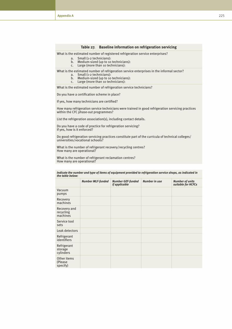
225 Appendix A
Table 27. Baseline information on refrigeration servicing
What is the estimated number of registered refrigeration service enterprises? a. Small (1-2 technicians): b. Medium-sized (up to 10 technicians): c. Large (more than 10 technicians):
What is the estimated number of refrigeration service enterprises in the informal sector? a. Small (1-2 technicians): b. Medium-sized (up to 10 technicians): c. Large (more than 10 technicians):
What is the estimated number of refrigeration service technicians?
Do you have a certification scheme in place?
If yes, how many technicians are certified?
How many refrigeration service technicians were trained in good refrigeration servicing practices within the CFC phase-out programmes?
List the refrigeration association(s), including contact details.
Do you have a code of practice for refrigeration servicing?If yes, how is it enforced?
Do good refrigeration servicing practices constitute part of the curricula of technical colleges/universities/vocational schools?
What is the number of refrigerant recovery/recycling centres? How many are operational?
What is the number of refrigerant reclamation centres?How many are operational?
Indicate the number and type of items of equipment provided to refrigeration service shops, as indicated in the table below:
Number MLF-funded Number GEF-funded if applicable
Number in use Number of units suitable for HCFCs
Vacuum pumps
Recovery machines
Recovery and recycling machines
Service tool sets
Leak detectors
Refrigerant identifiers
Refrigerant storage cylinders
Other items (Please specify)

226 Preparing for HCFC phase-out: Fundamentals of uses, alternatives, implications and funding for Article 5 countries
Table 28. Sectors to be surveyed to determine the type and number of HCFC-based items of serviceable refrigeration and air-conditioning equipment
Explanatory note: Respond to the sector-specific questions and complete the data template as applicable.
a) Commercial and industry• Industrialfirmsusingrefrigerationand/orairconditioning
b) Agricultural users• Inventoryofcold-storagesystems• Dairyfarms• Surveyofconsumers
c) Infrastructure and buildings• Numberofhotels,restaurants,etc.• Numberofhospitals,banks,publicbuildings,etc.
d) Fishing industry• Number,namesandgeographicaldistributionofrefrigeratedfishingvesselsandtheir
displacement (tons), and fish processing units
e) Informal sector• Estimatednumberofworkersandworkshopsintherefrigerationsector• Estimatedgrowthtrendsintheinformalsector• Analysisofthestructureofthissector
f) Education and vocational training• Dataontrainingcentresforoccupationsconnectedwithrefrigeration• Analysisofthequalityoftraining
g) Transport: • Estimatednumberofair-conditionedvehiclesandtrends• Estimatednumberofrefrigeratedvehiclesandtrends
h) Domestic refrigeration statistics• Numberofhouseholdswithrefrigerators,freezers,airconditioning,and• Numberofair-conditionedvehicles,macroeconomicdataandtrendsingrowth
i) Importers:• QuantitiesandtypesofimportedODSsandtrends• Namesofcustomersandtypesofbusiness
j) Distributors:• QuantitiesandtypesofODSsdistributedandtrends
k) End users:• Typeofactivity• QuantitiesandtypesofODSsconsumedandtrendsinneeds• Qualificationsofpersonnel
EquipmentEstimated No. of HCFC-based units in operation
Estimated annual HCFC consumption for 2007 or latest (Please indicate the year.)
Room air conditioners
Chillers
Refrigerated and/or cooled transportation equipment: busses, trains, trucks, ships, containers
Domestic and light commercial refrigeration
Commercial and industrial refrigeration systems
TOTAL

227 Appendix A
Dat
a te
mpl
ates
for s
ervi
ce w
orks
hops
Nam
e
Num
ber o
f em
ploy
ees
Empl
oyee
qua
lifica
tions
Des
crip
tion
of c
ompa
ny
Inve
ntor
y or
ser
vice
equ
ipm
ent
(vac
uum
pum
ps, r
ecov
ery
mac
hine
s, g
auge
s, e
tc.)
Type
s of
equ
ipm
ent s
ervi
ced,
No.
per
yea
rEs
timat
ed le
akag
e ra
te/y
ear
Room
A/C
Chill
ers
Tran
spor
tD
omes
tic a
nd li
ght
com
mer
cial
Com
mer
cial
and
in
dust
rial
Refr
iger
ant u
sed
(Add
col
umns
as
appr
opri
ate.
)H
CFC-
22H
CFC-
123
HCF
C-12
4O
ther
Kg p
er y
ear
Nam
es a
nd a
ddre
sses
of r
efri
gera
nt s
uppl
iers
Com
men
ts a
nd o
bser
vatio
ns
(Lev
el o
f pra
ctic
e, a
war
enes
s of
CFC
pha
se-o
ut, u
se
of a
ltern
ativ
es, e
tc.)

228 Preparing for HCFC phase-out: Fundamentals of uses, alternatives, implications and funding for Article 5 countries
Dat
a te
mpl
ates
for s
ervi
ce w
orks
hops
Nam
e
Num
ber o
f em
ploy
ees
Des
crip
tion
of c
ompa
ny
Inve
ntor
y of
refr
iger
atio
n eq
uipm
ent a
nd
desc
ript
ion
of h
ow it
is u
sed
(e.g
., pr
oces
s co
olin
g, fo
od s
tora
ge, a
irtja
noc
h 15
vo
r co
nditi
onin
g, e
tc.)
Refr
iger
ant c
onsu
med
Cons
umpt
ion,
kg
per y
ear
HCF
C-22
HCF
C-12
3H
CFC-
124
Oth
er
Nam
es a
nd a
ddre
sses
of r
efri
gera
nt s
uppl
iers
HCF
C-22
HCF
C-12
3H
CFC-
124
Ble
nds
Oth
er (P
leas
e na
me.
)
Nam
e an
d ad
dres
s of
refr
iger
atio
n se
rvic
e co
mpa
ny
Com
men
ts a
nd o
bser
vatio
ns
(Lev
el o
f pra
ctic
e, a
war
enes
s of
CFC
pha
se-o
ut,
use
of a
ltern
ativ
es, e
tc.)

229 Appendix A
Tabl
e 29
. H
CFC
cons
umpt
ion
in re
frig
erat
ion
serv
icin
g (m
etri
c to
nnes
)
Year
HCF
C-22
HCF
C-12
3O
ther
/ble
ndH
CFC-
141b
(fl
ushi
ng/c
lean
ing)
Tota
l
2003
2004
2005
2006
2007
2008
*
2009
*
2010
*
2011
*
2012
*
*Est
imat
e


UNITED NATIONS INDUSTRIAL DEVELOPMENT ORGANIZATION
Printed in AustriaV.09-83747—August 2009—750
UNITED NATIONS INDUSTRIAL DEVELOPMENT ORGANIZATIONVienna International Centre, P.O. Box 300, 1400 Vienna, AustriaTelephone: (+43-1) 26026-0, Fax: (+43-1) 26926-69E-mail: [email protected], Internet: www.unido.org
Preparing for HCFC phase-out:
Fundamentals of uses, alternatives, implications and funding for Article 5 countries
Preparing for HCFC phase-out: Fundam
entals of uses, alternatives, implications and funding for Article 5 countries